node builder users guide
TRANSCRIPT

1 | P a g e
eOne Integrated Business Solutions
Node Builder Users Guide
2 | P a g e
eOne Integrated Business Solutions ..................................................................................................... 1
Node Builder Overview ................................................................................................................................. 4
Understanding Node Builder ........................................................................................................................ 5
MAIN SCREEN ............................................................................................................................................ 5
FILE MENU OPTIONS ............................................................................................................................. 5
NEW .................................................................................................................................................. 5
OPEN ................................................................................................................................................. 5
SAVE .................................................................................................................................................. 5
IMPORT ............................................................................................................................................. 5
EXPORT .............................................................................................................................................. 5
DELETE NODE .................................................................................................................................... 6
TOOLS MENU OPTIONS ......................................................................................................................... 6
REGISTRATION .................................................................................................................................. 6
SETUP ................................................................................................................................................ 6
HELP MENU OPTIONS ........................................................................................................................... 6
ABOUT ............................................................................................................................................... 6
MAIN TOOLBAR ..................................................................................................................................... 6
CONNECTION WINDOW ............................................................................................................................ 7
SETUP ........................................................................................................................................................ 8
TABLES ..................................................................................................................................................... 10
ADD TABLES ........................................................................................................................................ 12
LOGIC-LOOKUPS .................................................................................................................................. 13
ADD LOOKUP ................................................................................................................................... 15
LOGIC-USER DEFINED .......................................................................................................................... 16
SECURITY ................................................................................................................................................. 18
ERROR CODES ......................................................................................................................................... 19
OUTPUT PARAMETERS ........................................................................................................................ 20
LOGIC ...................................................................................................................................................... 21
CALCULATIONS .................................................................................................................................... 21
CREATE FUNCTION .......................................................................................................................... 28
RETURN ERROR ............................................................................................................................... 31
SET VALUE ....................................................................................................................................... 32

3 | P a g e
PUBLISH ................................................................................................................................................... 36
Using Node Builder ..................................................................................................................................... 37
1. CREATING A BASIC NODE EXERCISE (15 MINUTES) ........................................................................ 37
CREATE CONNECTION ......................................................................................................................... 37
CONFIGURE SETUP .............................................................................................................................. 38
ADD TABLE .......................................................................................................................................... 39
PUBLISH ............................................................................................................................................... 41
SMARTCONNECT ................................................................................................................................. 41
2. CREATING AN ADVANCED NODE (60 MINUTES) ............................................................................. 42
CREATE CONNECTION ......................................................................................................................... 42
CONFIGURE SETUP .............................................................................................................................. 42
ADD TABLES ........................................................................................................................................ 44
ADD USER DEFINED FIELD ................................................................................................................... 46
ADD LOOKUP ....................................................................................................................................... 48
ADD ERROR CODE ............................................................................................................................... 51
ADD CALCULATION ............................................................................................................................. 53
PUBLISH ............................................................................................................................................... 61
SMARTCONNECT ................................................................................................................................. 61

4 | P a g e
Node Builder Overview
The Node Builder product allows users to create new eConnect SQL Server stored procedures and has a
seamless integration to SmartConnect. This powerful tool will help you integrate into any Dynamics GP
or Third Party table as well as custom tables. You can now create a new eConnect node in minutes or
take additional time and add any logic that you desire using the intuitive interface. If you have ever
created a SmartList using SmartList Builder, you have all the knowledge you need and can now create
new integration objects for Dynamics GP.
We have provided two exercises that further explore the features of Node Builder through a practical
example. The first exercise should take less than 15 minutes to complete, resulting in a fully functional
new eConnect node. The second exercise offers a much broader look at adding logic to an eConnect
node to ensure data integrity.

5 | P a g e
Understanding Node Builder
MAIN SCREEN
FILE MENU OPTIONS
NEW
The New option will clear out existing work. The connection information that was entered
will be saved so it does not have to be re-setup.
OPEN
The Open option allows opening a saved by Node Builder after you have created a
connection to a SQL Server. All companies and users will be unchecked when the Node is
opened.
SAVE
The Save option will allow saving a Node to edit at a later time. The Node ID field must be
populated in order to continue.
IMPORT
The Import option will allow importing a Node from an xml file that was created using the
Export option.
EXPORT
The Export option will allow saving the Node to an xml file. The file can then be opened by
any install of Node Builder (i.e. an install on a production server or from a partner site to a
customer site) using the Import option. The save file path will default to the location of the
Node Builder application, and the xml file name will default to the Node ID.
6 | P a g e
DELETE NODE
The Delete Node option will allow removing an existing node. It will not remove any of the
SQL object but will just remove the definition of the Node.
TOOLS MENU OPTIONS
REGISTRATION
Node Builder can be used without registration keys in the Dynamics GP sample company,
Fabrikam. In order to create nodes in other Dynamics GP companies, the product must be
registered. All of the functionality will be present in Node Builder without registration keys,
however nodes cannot be published in any company besides Fabrikam until registration is
complete.
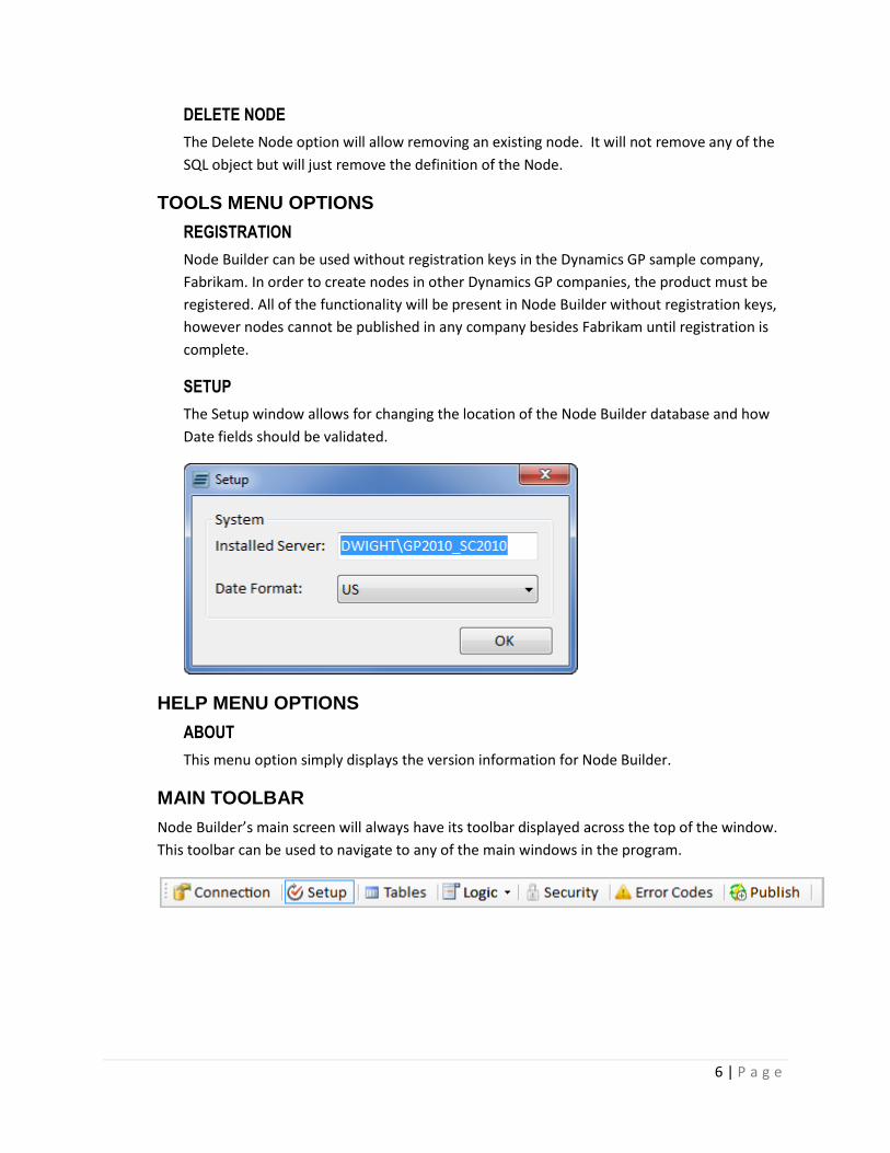
SETUP
The Setup window allows for changing the location of the Node Builder database and how
Date fields should be validated.
HELP MENU OPTIONS
ABOUT
This menu option simply displays the version information for Node Builder.
MAIN TOOLBAR
Node Builder’s main screen will always have its toolbar displayed across the top of the window.
This toolbar can be used to navigate to any of the main windows in the program.
7 | P a g e
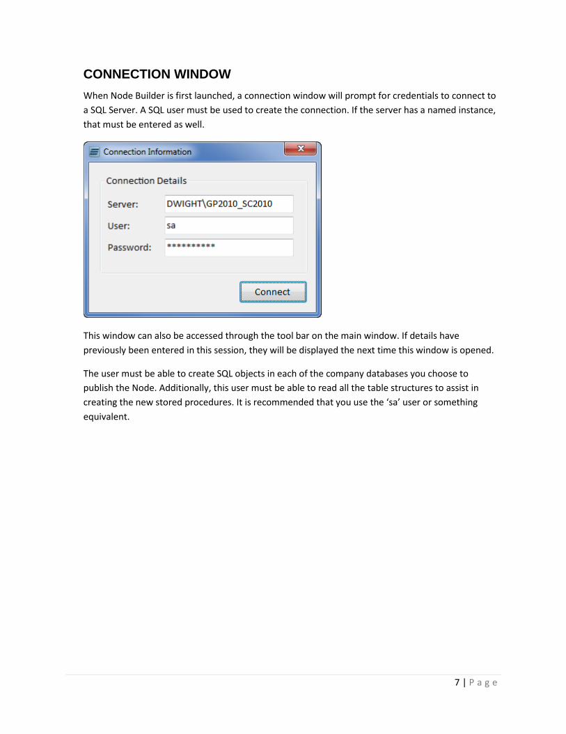
CONNECTION WINDOW
When Node Builder is first launched, a connection window will prompt for credentials to connect to
a SQL Server. A SQL user must be used to create the connection. If the server has a named instance,
that must be entered as well.
This window can also be accessed through the tool bar on the main window. If details have
previously been entered in this session, they will be displayed the next time this window is opened.
The user must be able to create SQL objects in each of the company databases you choose to
publish the Node. Additionally, this user must be able to read all the table structures to assist in
creating the new stored procedures. It is recommended that you use the ‘sa’ user or something
equivalent.
8 | P a g e
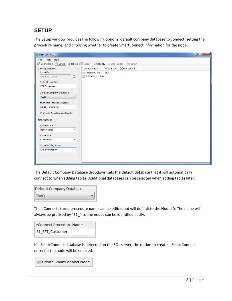
SETUP
The Setup window provides the following options: default company database to connect, setting the
procedure name, and choosing whether to create SmartConnect information for the node.
The Default Company Database dropdown sets the default database that it will automatically
connect to when adding tables. Additional databases can be selected when adding tables later.
The eConnect stored procedure name can be edited but will default to the Node ID. The name will
always be prefixed by “E1_” so the nodes can be identified easily.
If a SmartConnect database is detected on the SQL server, the option to create a SmartConnect
entry for the node will be enabled.

9 | P a g e
Once the SmartConnect node checkbox is marked, Node Groups and Types can be selected from
existing Node Groups and Types or new ones can be created. The Node Group and Type selected will
determine where the entry is created within SmartConnect. You can then enter a display name for
the node in SmartConnect.
The right side of the Setup window displays a list of Dynamics GP companies that exist in the current
server specified in the Connection window. If a company is checked, it will be created in that
company when the node is published. A Node can be created in multiple companies if more than
one company is checked.
A Node will not be able to be published until at least one company is selected.
10 | P a g e
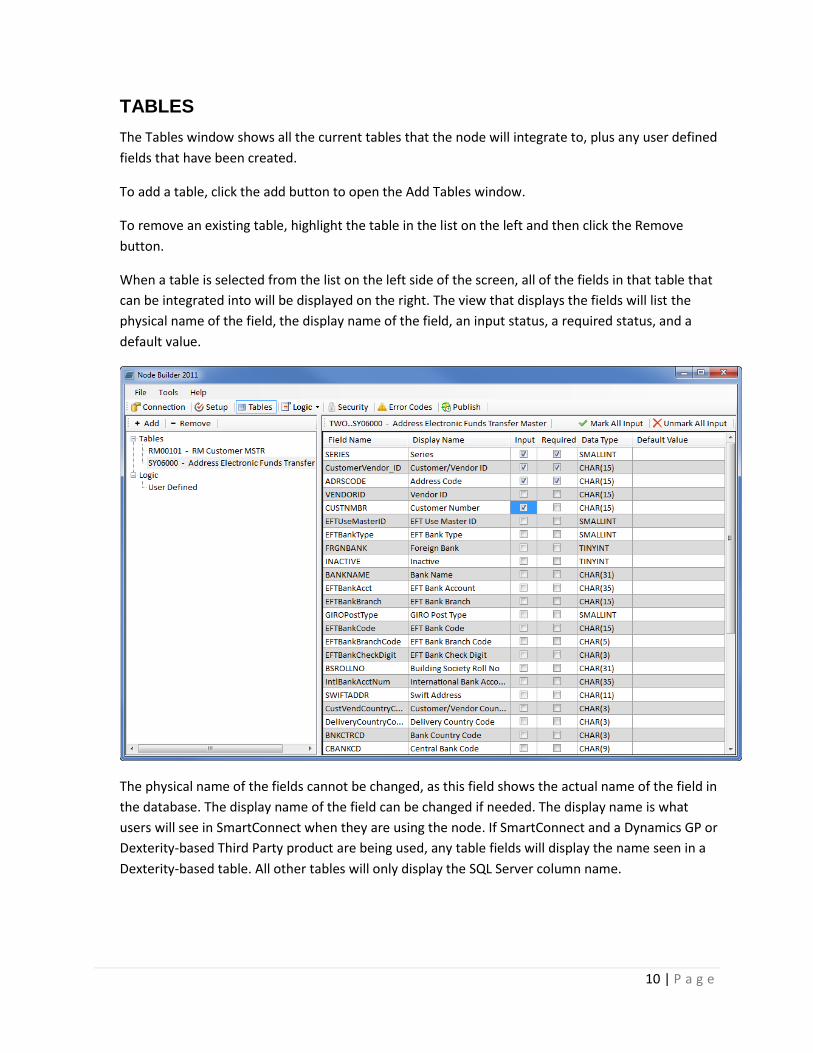
TABLES
The Tables window shows all the current tables that the node will integrate to, plus any user defined
fields that have been created.
To add a table, click the add button to open the Add Tables window.
To remove an existing table, highlight the table in the list on the left and then click the Remove
button.
When a table is selected from the list on the left side of the screen, all of the fields in that table that
can be integrated into will be displayed on the right. The view that displays the fields will list the
physical name of the field, the display name of the field, an input status, a required status, and a
default value.
The physical name of the fields cannot be changed, as this field shows the actual name of the field in
the database. The display name of the field can be changed if needed. The display name is what
users will see in SmartConnect when they are using the node. If SmartConnect and a Dynamics GP or
Dexterity-based Third Party product are being used, any table fields will display the name seen in a
Dexterity-based table. All other tables will only display the SQL Server column name.
11 | P a g e
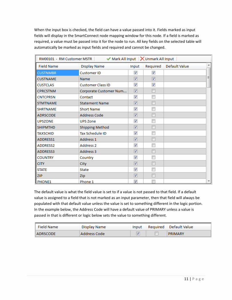
When the input box is checked, the field can have a value passed into it. Fields marked as input
fields will display in the SmartConnect node mapping window for this node. If a field is marked as
required, a value must be passed into it for the node to run. All key fields on the selected table will
automatically be marked as input fields and required and cannot be changed.
The default value is what the field value is set to if a value is not passed to that field. If a default
value is assigned to a field that is not marked as an input parameter, then that field will always be
populated with that default value unless the value is set to something different in the logic portion.
In the example below, the Address Code will have a default value of PRIMARY unless a value is
passed in that is different or logic below sets the value to something different.

12 | P a g e
ADD TABLES
The Add Tables window opens when the Add button is pressed on the Tables screen in the main
window. This window allows the user to select a database, or change it from the default
database selected on the Setup window. After a database is selected, this window will populate
with a list of available tables. One or more tables can be checked and when submitted, the
selected tables will be added to the node.

13 | P a g e
LOGIC-LOOKUPS
The Lookups screen can be used to retrieve values from other tables in the server. On the left
side of the screen is a list that contains any existing lookups in the node. If the user selects an
existing lookup, the details of that lookup will be displayed on the right side of the screen.
When the user hits the Add button, the Add Lookup window will pop up where the user can
select the field needed for the lookup. Once that window is submitted, a new lookup will be
created.
14 | P a g e
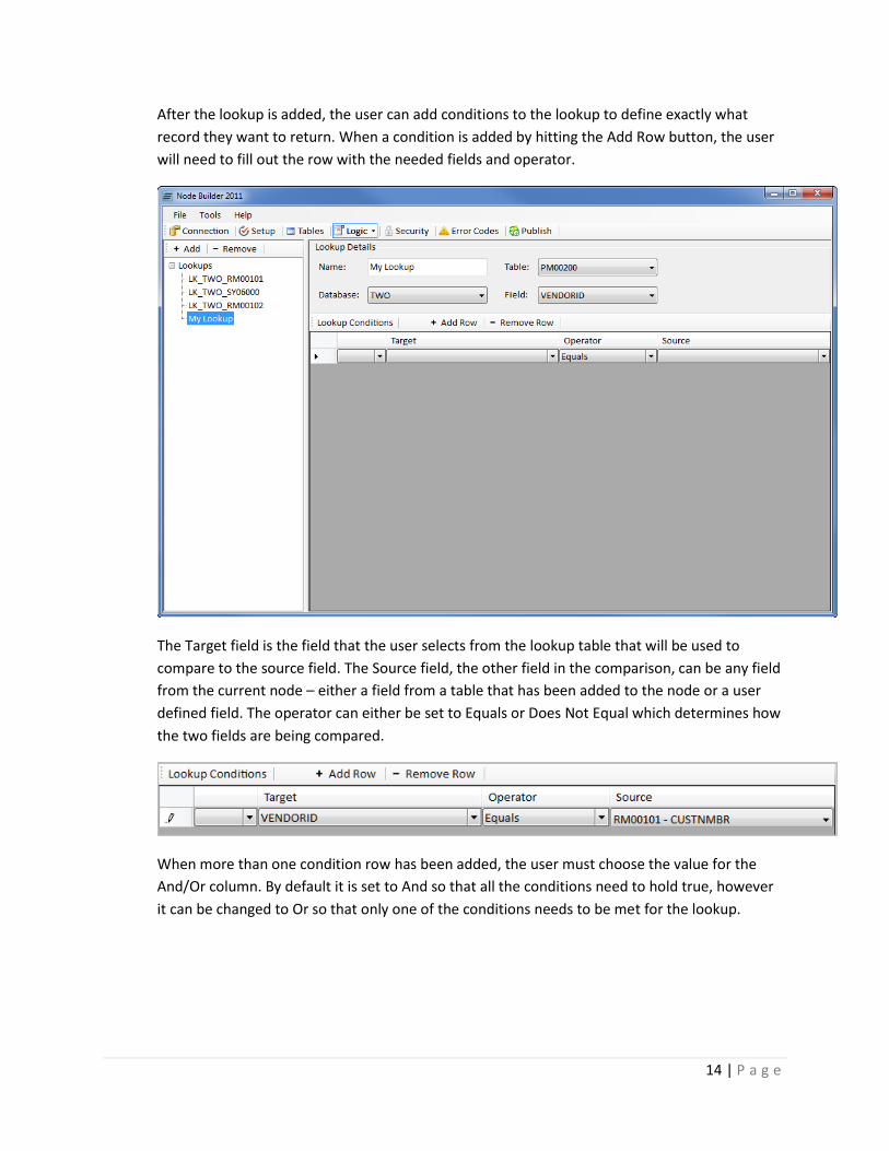
After the lookup is added, the user can add conditions to the lookup to define exactly what
record they want to return. When a condition is added by hitting the Add Row button, the user
will need to fill out the row with the needed fields and operator.
The Target field is the field that the user selects from the lookup table that will be used to
compare to the source field. The Source field, the other field in the comparison, can be any field
from the current node – either a field from a table that has been added to the node or a user
defined field. The operator can either be set to Equals or Does Not Equal which determines how
the two fields are being compared.
When more than one condition row has been added, the user must choose the value for the
And/Or column. By default it is set to And so that all the conditions need to hold true, however
it can be changed to Or so that only one of the conditions needs to be met for the lookup.
15 | P a g e
Note that if a lookup returns more than one value, it will return the first match that is found
based on the conditions.
For every table that is added by the user, the system will automatically create a lookup based off
of that table. All the lookups that are automatically generated will check if a record exists or not.
The conditions for the lookups are based off the key fields of each table, so for every key field
there will be a lookup condition.
These lookups are used in the calculation section to determine if a record already exists for each
table. If a record is found, it will either be updated or the node will return an error if it is set to
update existing records.
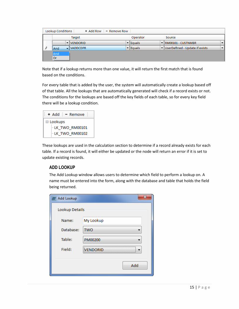
ADD LOOKUP
The Add Lookup window allows users to determine which field to perform a lookup on. A
name must be entered into the form, along with the database and table that holds the field
being returned.

16 | P a g e
The field dropdown list contains all fields in the selected table along with a “Check if Record
Exists” option. This option will return a 1 for records found meeting the conditions. Once
added, the name can be modified from the main Lookup window.
LOGIC-USER DEFINED
If custom fields are needed for storing values or being used in calculations, the User Defined
screen can be used to create new parameters. Commonly, a User Defined field may be used for
options (i.e. Default Distributions, Roll-down information from a class, etc.).
When a user defined field is added by hitting the Add Row button, it will create a new field with
its default properties. This new field can be modified by changing the display name, data type,
and its default value if needed.
The Field Name column cannot be changed, as this is determined automatically and will be used
by the system as the identifier for the custom field. The Display Name can be changed however,
and this will be the display name in SmartConnect when mapping to this field.
17 | P a g e
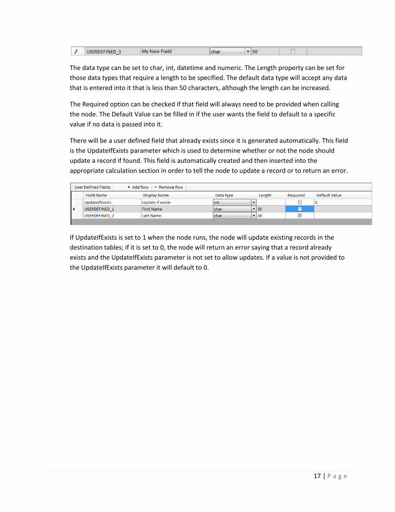
The data type can be set to char, int, datetime and numeric. The Length property can be set for
those data types that require a length to be specified. The default data type will accept any data
that is entered into it that is less than 50 characters, although the length can be increased.
The Required option can be checked if that field will always need to be provided when calling
the node. The Default Value can be filled in if the user wants the field to default to a specific
value if no data is passed into it.
There will be a user defined field that already exists since it is generated automatically. This field
is the UpdateIfExists parameter which is used to determine whether or not the node should
update a record if found. This field is automatically created and then inserted into the
appropriate calculation section in order to tell the node to update a record or to return an error.
If UpdateIfExists is set to 1 when the node runs, the node will update existing records in the
destination tables; if it is set to 0, the node will return an error saying that a record already
exists and the UpdateIfExists parameter is not set to allow updates. If a value is not provided to
the UpdateIfExists parameter it will default to 0.
18 | P a g e
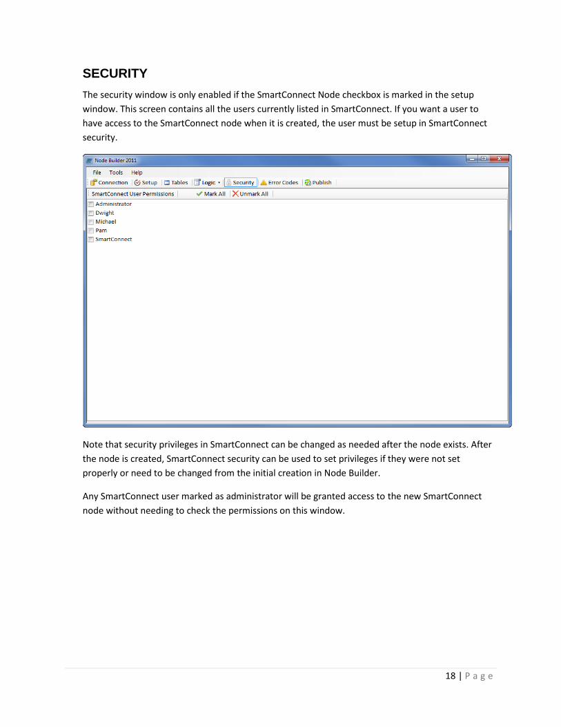
SECURITY
The security window is only enabled if the SmartConnect Node checkbox is marked in the setup
window. This screen contains all the users currently listed in SmartConnect. If you want a user to
have access to the SmartConnect node when it is created, the user must be setup in SmartConnect
security.
Note that security privileges in SmartConnect can be changed as needed after the node exists. After
the node is created, SmartConnect security can be used to set privileges if they were not set
properly or need to be changed from the initial creation in Node Builder.
Any SmartConnect user marked as administrator will be granted access to the new SmartConnect
node without needing to check the permissions on this window.
19 | P a g e
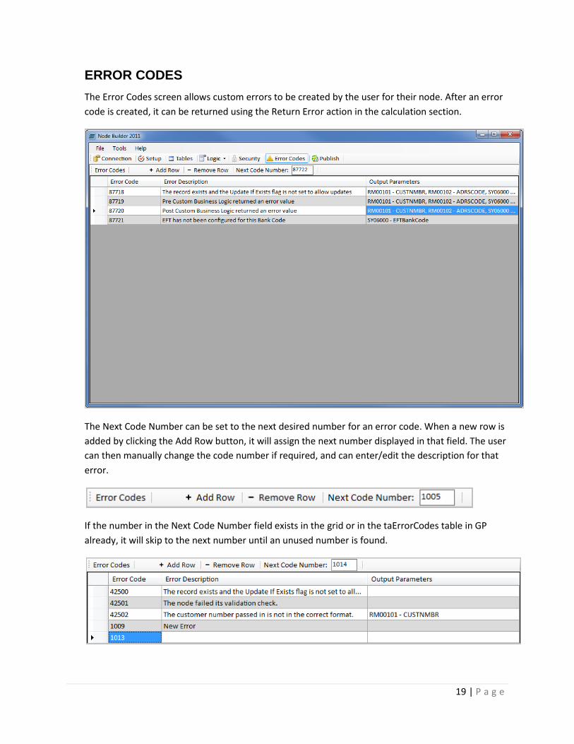
ERROR CODES
The Error Codes screen allows custom errors to be created by the user for their node. After an error
code is created, it can be returned using the Return Error action in the calculation section.
The Next Code Number can be set to the next desired number for an error code. When a new row is
added by clicking the Add Row button, it will assign the next number displayed in that field. The user
can then manually change the code number if required, and can enter/edit the description for that
error.
If the number in the Next Code Number field exists in the grid or in the taErrorCodes table in GP
already, it will skip to the next number until an unused number is found.

20 | P a g e
The Output Parameters column lets the user choose whether or not they want to return any fields
and their associated values with the error message. If a user double clicks in the Output Parameters
field, it will open a window which lists all of the fields from the tables that have been added to the
node. If the error message gets returned when the node is actually running, any fields that are
marked as output parameters will be returned with their values.
Three error codes are generated automatically by the system. One for the Pre Procedure, one for
the Post Procedure and another for the Update if Exists parameter.
OUTPUT PARAMETERS
The Output Parameters window contains all fields of the tables included in the current node.
The user can check up to 10 Output Parameters to accompany each error code.
21 | P a g e
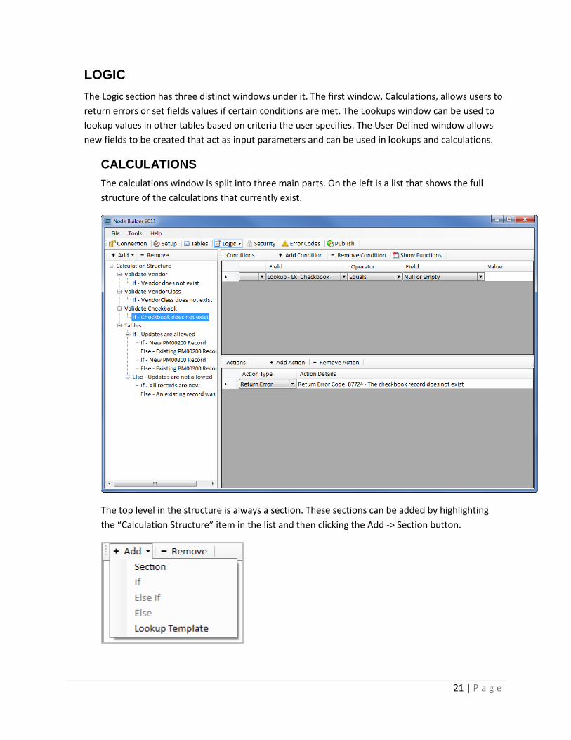
LOGIC
The Logic section has three distinct windows under it. The first window, Calculations, allows users to
return errors or set fields values if certain conditions are met. The Lookups window can be used to
lookup values in other tables based on criteria the user specifies. The User Defined window allows
new fields to be created that act as input parameters and can be used in lookups and calculations.
CALCULATIONS
The calculations window is split into three main parts. On the left is a list that shows the full
structure of the calculations that currently exist.
The top level in the structure is always a section. These sections can be added by highlighting
the “Calculation Structure” item in the list and then clicking the Add -> Section button.
22 | P a g e
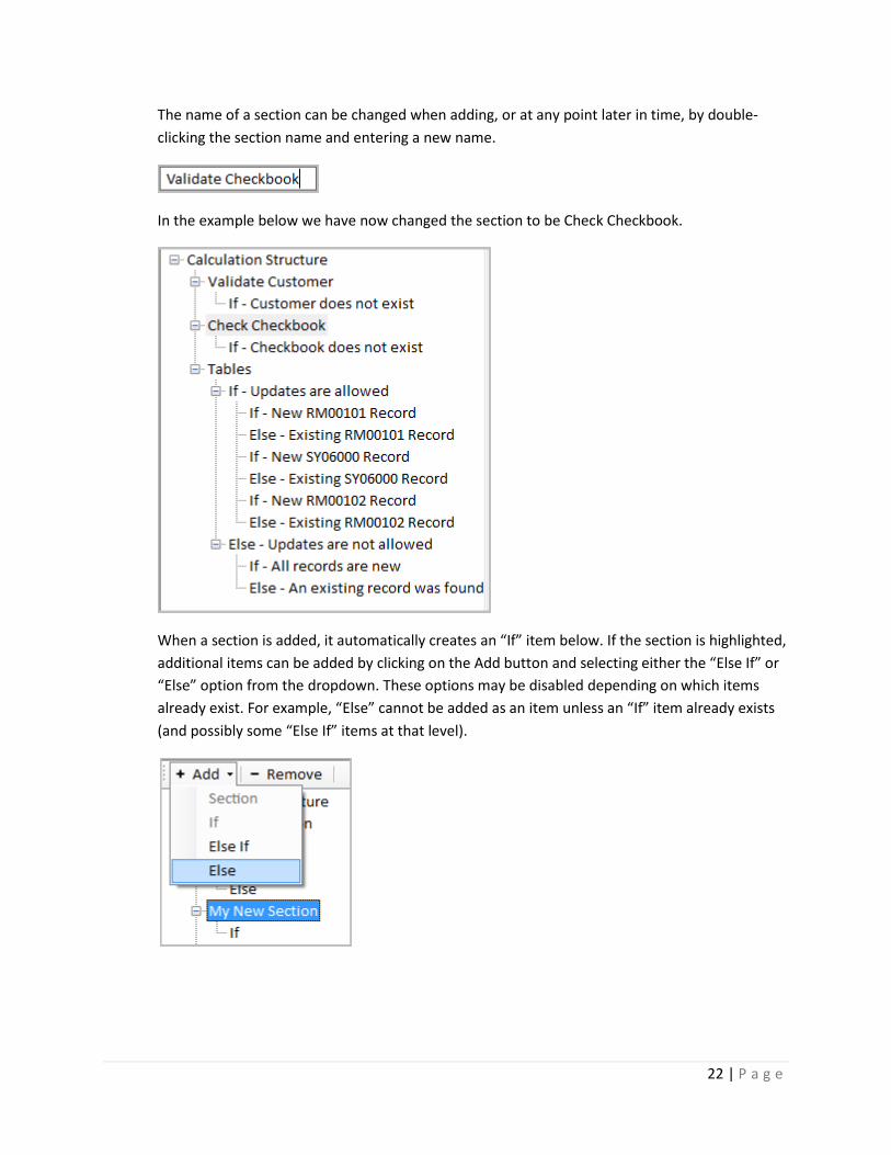
The name of a section can be changed when adding, or at any point later in time, by double-
clicking the section name and entering a new name.
In the example below we have now changed the section to be Check Checkbook.
When a section is added, it automatically creates an “If” item below. If the section is highlighted,
additional items can be added by clicking on the Add button and selecting either the “Else If” or
“Else” option from the dropdown. These options may be disabled depending on which items
already exist. For example, “Else” cannot be added as an item unless an “If” item already exists
(and possibly some “Else If” items at that level).
23 | P a g e
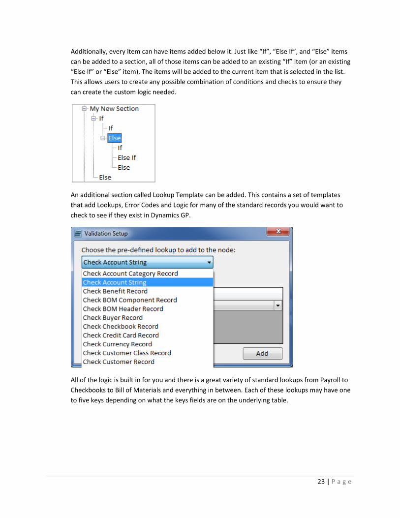
Additionally, every item can have items added below it. Just like “If”, “Else If”, and “Else” items
can be added to a section, all of those items can be added to an existing “If” item (or an existing
“Else If” or “Else” item). The items will be added to the current item that is selected in the list.
This allows users to create any possible combination of conditions and checks to ensure they
can create the custom logic needed.
An additional section called Lookup Template can be added. This contains a set of templates
that add Lookups, Error Codes and Logic for many of the standard records you would want to
check to see if they exist in Dynamics GP.
All of the logic is built in for you and there is a great variety of standard lookups from Payroll to
Checkbooks to Bill of Materials and everything in between. Each of these lookups may have one
to five keys depending on what the keys fields are on the underlying table.
24 | P a g e
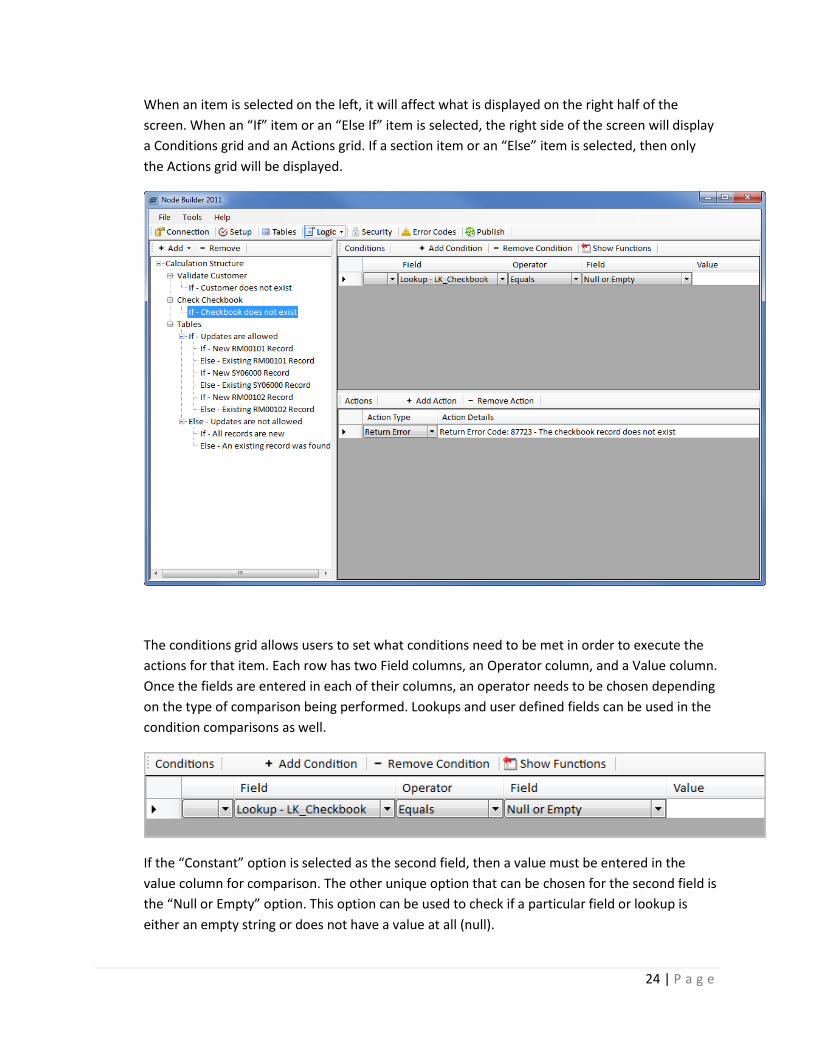
When an item is selected on the left, it will affect what is displayed on the right half of the
screen. When an “If” item or an “Else If” item is selected, the right side of the screen will display
a Conditions grid and an Actions grid. If a section item or an “Else” item is selected, then only
the Actions grid will be displayed.
The conditions grid allows users to set what conditions need to be met in order to execute the
actions for that item. Each row has two Field columns, an Operator column, and a Value column.
Once the fields are entered in each of their columns, an operator needs to be chosen depending
on the type of comparison being performed. Lookups and user defined fields can be used in the
condition comparisons as well.
If the “Constant” option is selected as the second field, then a value must be entered in the
value column for comparison. The other unique option that can be chosen for the second field is
the “Null or Empty” option. This option can be used to check if a particular field or lookup is
either an empty string or does not have a value at all (null).

25 | P a g e
When more than one row is added to the condition grid, the first column in the grid will have an
“And” and an “Or” option. These options can be used to determine whether all the conditions
need to be met (And), or if only one of them needs to be met (Or).
If the Show Functions is clicked, it enable functions for the conditions. A function column will
become visible just before each field column in the grid. If the user double-clicks the function
cell, it will pop up a window where the user can select the function that they want to perform
on the selected field. When that window is closed, the chosen function will appear in the cell,
which can be changed by double-clicking it again and selecting a different option.
26 | P a g e
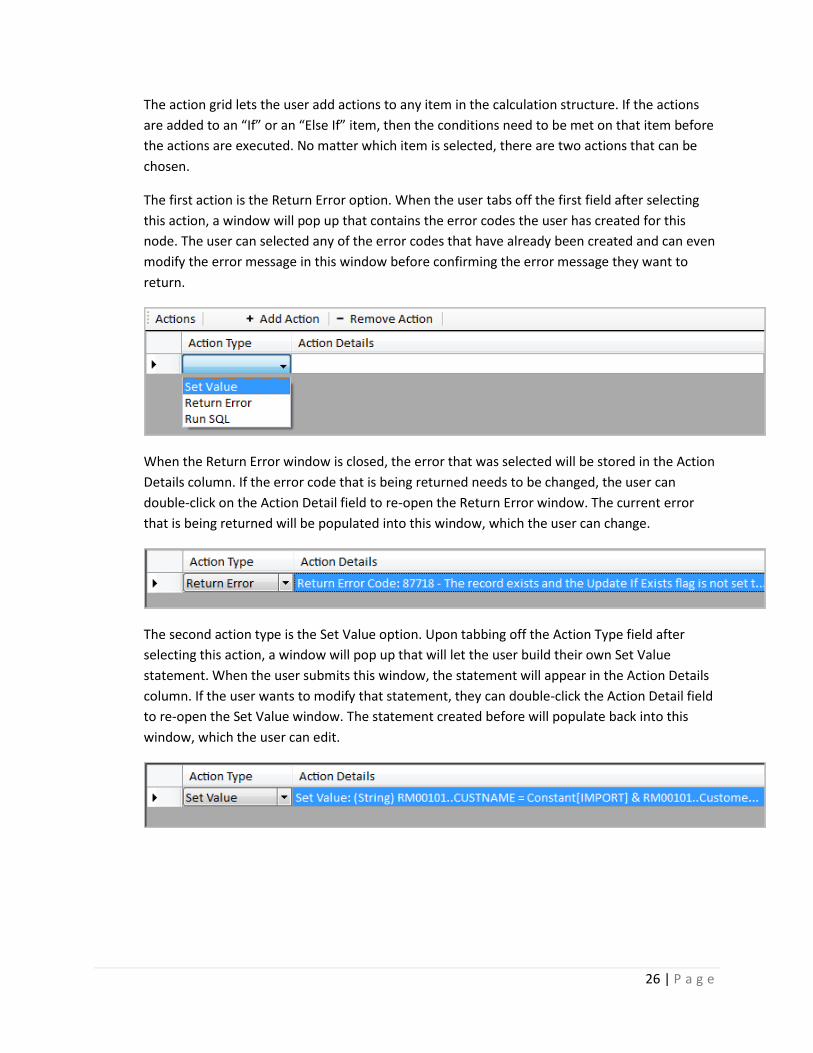
The action grid lets the user add actions to any item in the calculation structure. If the actions
are added to an “If” or an “Else If” item, then the conditions need to be met on that item before
the actions are executed. No matter which item is selected, there are two actions that can be
chosen.
The first action is the Return Error option. When the user tabs off the first field after selecting
this action, a window will pop up that contains the error codes the user has created for this
node. The user can selected any of the error codes that have already been created and can even
modify the error message in this window before confirming the error message they want to
return.
When the Return Error window is closed, the error that was selected will be stored in the Action
Details column. If the error code that is being returned needs to be changed, the user can
double-click on the Action Detail field to re-open the Return Error window. The current error
that is being returned will be populated into this window, which the user can change.
The second action type is the Set Value option. Upon tabbing off the Action Type field after
selecting this action, a window will pop up that will let the user build their own Set Value
statement. When the user submits this window, the statement will appear in the Action Details
column. If the user wants to modify that statement, they can double-click the Action Detail field
to re-open the Set Value window. The statement created before will populate back into this
window, which the user can edit.
27 | P a g e
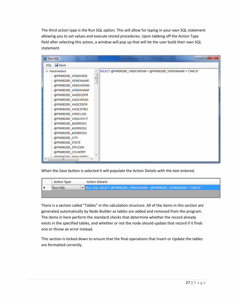
The third action type is the Run SQL option. This will allow for typing in your own SQL statement
allowing you to set values and execute stored procedures. Upon tabbing off the Action Type
field after selecting this action, a window will pop up that will let the user build their own SQL
statement.
When the Save button is selected it will populate the Action Details with the text entered.
There is a section called “Tables” in the calculation structure. All of the items in this section are
generated automatically by Node Builder as tables are added and removed from the program.
The items in here perform the standard checks that determine whether the record already
exists in the specified tables, and whether or not the node should update that record if it finds
one or throw an error instead.
This section is locked down to ensure that the final operations that Insert or Update the tables
are formatted correctly.
28 | P a g e
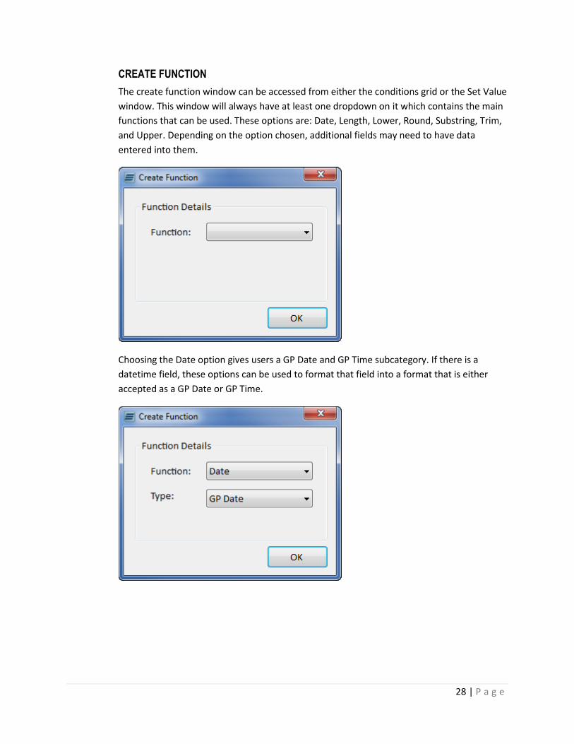
CREATE FUNCTION
The create function window can be accessed from either the conditions grid or the Set Value
window. This window will always have at least one dropdown on it which contains the main
functions that can be used. These options are: Date, Length, Lower, Round, Substring, Trim,
and Upper. Depending on the option chosen, additional fields may need to have data
entered into them.
Choosing the Date option gives users a GP Date and GP Time subcategory. If there is a
datetime field, these options can be used to format that field into a format that is either
accepted as a GP Date or GP Time.

29 | P a g e
The Length option returns the length of the field where the function has been applied.
The Lower option converts the field value to lowercase.
The Upper option converts the field to uppercase.
30 | P a g e
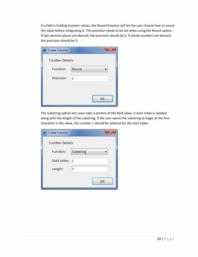
If a field is holding numeric values, the Round function will let the user choose how to round
the value before integrating it. The precision needs to be set when using the Round option.
If two decimal places are desired, the precision should be 2. If whole numbers are desired,
the precision should be 0.
The Substring option lets users take a portion of the field value. A start index is needed
along with the length of the substring. If the user wants the substring to begin at the first
character in the value, the number 1 should be entered for the start index.

31 | P a g e
Fields can have any extra white spaces removed from them by using the Trim option. When
Trim is chosen, the user needs to either chose to perform a left trim, right trim, or a full trim
on the field.
RETURN ERROR
This window is displayed when the Return Error action type is chosen in the action grid and
the user has tabbed-off the field. The dropdown list in this window lists all the current error
codes that have been created for this node. When the user selects one of these error codes,
it displays the full description of the error in the text box on the window. The description
can be changed inside of this window before saving it, which will update the description of
the node in the Error Code screen.
32 | P a g e
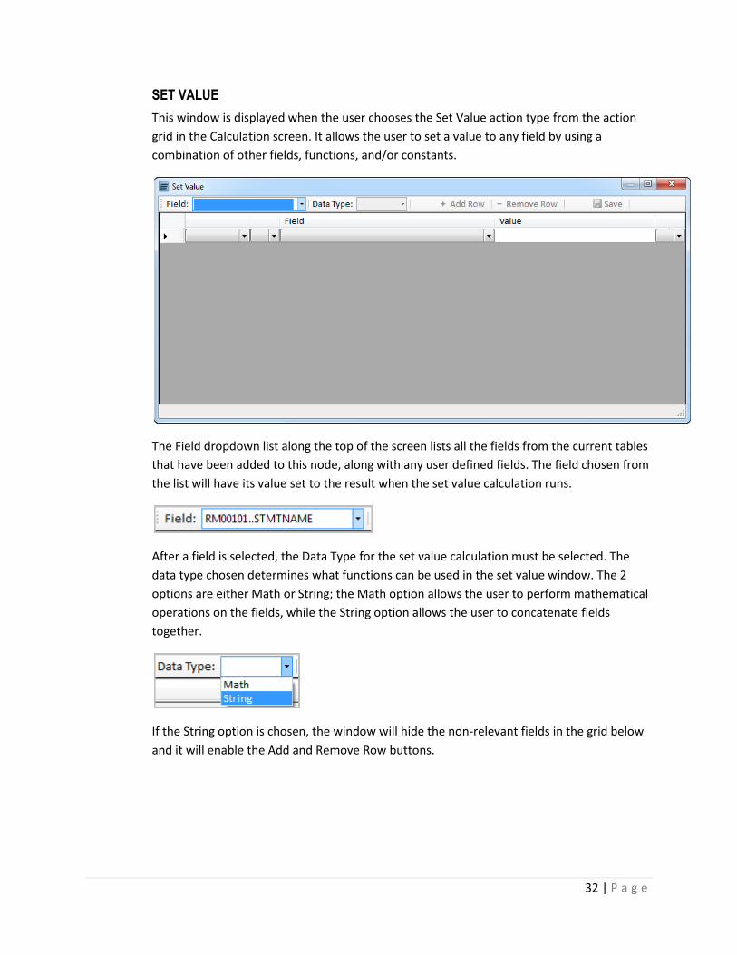
SET VALUE
This window is displayed when the user chooses the Set Value action type from the action
grid in the Calculation screen. It allows the user to set a value to any field by using a
combination of other fields, functions, and/or constants.
The Field dropdown list along the top of the screen lists all the fields from the current tables
that have been added to this node, along with any user defined fields. The field chosen from
the list will have its value set to the result when the set value calculation runs.
After a field is selected, the Data Type for the set value calculation must be selected. The
data type chosen determines what functions can be used in the set value window. The 2
options are either Math or String; the Math option allows the user to perform mathematical
operations on the fields, while the String option allows the user to concatenate fields
together.
If the String option is chosen, the window will hide the non-relevant fields in the grid below
and it will enable the Add and Remove Row buttons.
33 | P a g e
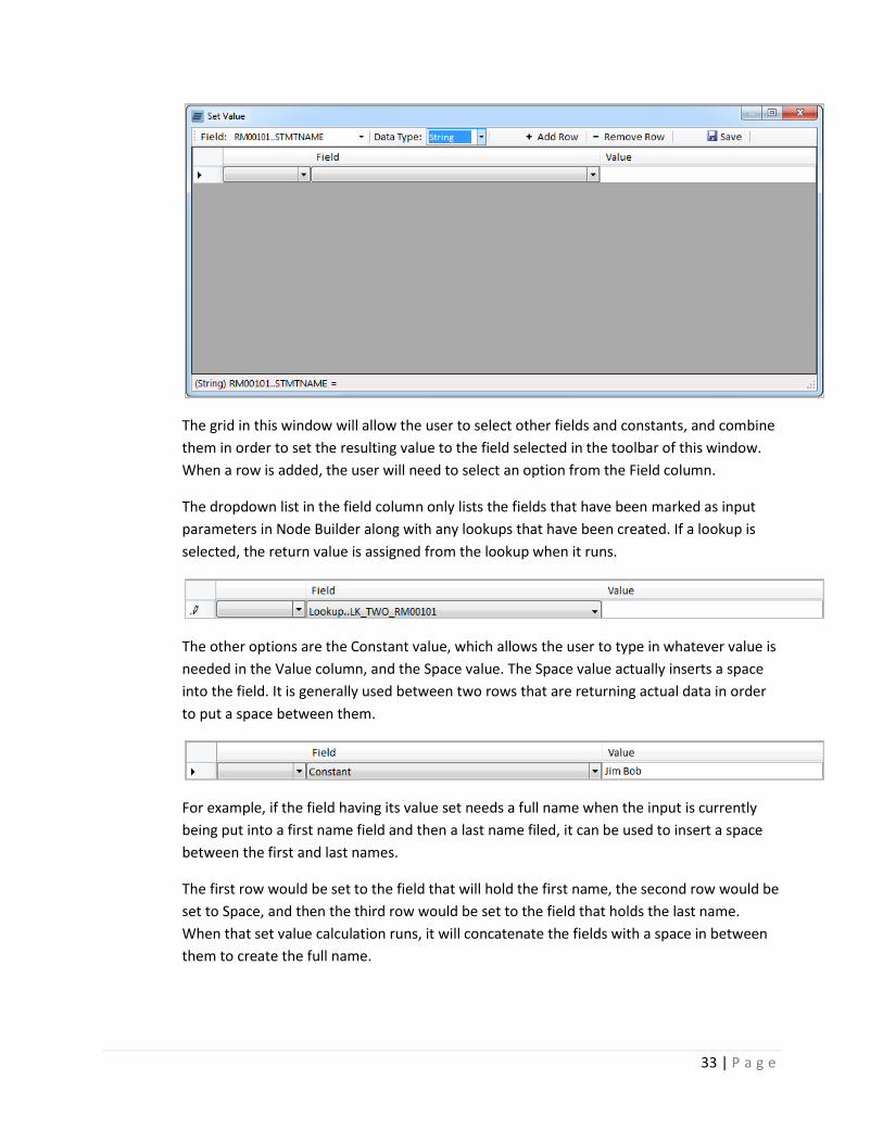
The grid in this window will allow the user to select other fields and constants, and combine
them in order to set the resulting value to the field selected in the toolbar of this window.
When a row is added, the user will need to select an option from the Field column.
The dropdown list in the field column only lists the fields that have been marked as input
parameters in Node Builder along with any lookups that have been created. If a lookup is
selected, the return value is assigned from the lookup when it runs.
The other options are the Constant value, which allows the user to type in whatever value is
needed in the Value column, and the Space value. The Space value actually inserts a space
into the field. It is generally used between two rows that are returning actual data in order
to put a space between them.
For example, if the field having its value set needs a full name when the input is currently
being put into a first name field and then a last name filed, it can be used to insert a space
between the first and last names.
The first row would be set to the field that will hold the first name, the second row would be
set to Space, and then the third row would be set to the field that holds the last name.
When that set value calculation runs, it will concatenate the fields with a space in between
them to create the full name.

34 | P a g e
If the Math option is chosen in the Data Type field, it will modify the grid below to show the
relevant fields. Also, if the Data Type is changed, after rows of data have been entered
under the other data type, those rows will be removed.
There are a couple of additions to the grid when using the Math data type compared to the
String type. The first change is the inclusion of 2 columns that allow use of parenthesis in the
grid.
The second change is that the user will need to select the needed operator for each row as
they are added. The operators available are Add, Subtract, Multiply, and Divide.
35 | P a g e
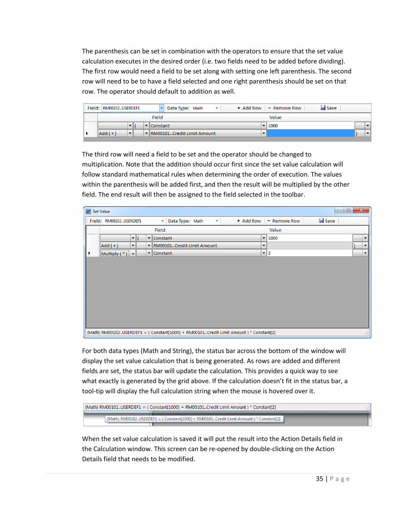
The parenthesis can be set in combination with the operators to ensure that the set value
calculation executes in the desired order (i.e. two fields need to be added before dividing).
The first row would need a field to be set along with setting one left parenthesis. The second
row will need to be to have a field selected and one right parenthesis should be set on that
row. The operator should default to addition as well.
The third row will need a field to be set and the operator should be changed to
multiplication. Note that the addition should occur first since the set value calculation will
follow standard mathematical rules when determining the order of execution. The values
within the parenthesis will be added first, and then the result will be multiplied by the other
field. The end result will then be assigned to the field selected in the toolbar.
For both data types (Math and String), the status bar across the bottom of the window will
display the set value calculation that is being generated. As rows are added and different
fields are set, the status bar will update the calculation. This provides a quick way to see
what exactly is generated by the grid above. If the calculation doesn’t fit in the status bar, a
tool-tip will display the full calculation string when the mouse is hovered over it.
When the set value calculation is saved it will put the result into the Action Details field in
the Calculation window. This screen can be re-opened by double-clicking on the Action
Details field that needs to be modified.

36 | P a g e
PUBLISH
The Publish button will create the eConnect node on your SQL Server and any associated
SmartConnect entries when it is clicked. It will create a node in each company that was checked in
the setup window and will add it to SmartConnect if those options were selected as well.
Note that if Node Builder has not been registered, then nodes will only be created in the Fabrikam
test company when the node is published.
When a node is published, it creates the actual SQL Server stored procedure in each of the marked
Dynamics GP companies. As the nodes are created, they will adjust the company databases used in
Node Builder to match the company that the node is currently being created in.
This means there cannot be a node in Fabrikam that updates a table in the Subsidiary company. So if
the node integrates into 2 tables in TWO (Fabrikam) and 1 table in TEST (some other database),
when the node is created in Fabrikam it will still integrate into 2 tables in TWO and 1 in TEST. When
the node is created in the Subsidiary company (SUB), however, it will integrate into 2 tables in SUB
and 1 in Test.
If you choose to create a new Node Group or Type you will need to restart Dynamics GP on the
client to see the new Node Groups or Types appear. Additionally, with the new eConnect Service on
Dynamics GP 2010 you may need to restart the eConnect Service if you add additional parameters
to your Node as the new service attempts to cache the parameters.
37 | P a g e
Using Node Builder
1. CREATING A BASIC NODE EXERCISE (15 MINUTES)
In this example, the user will create a new eConnect node to update a couple of fields on the Vendor
Maintenance card that are not included on some versions of eConnect.
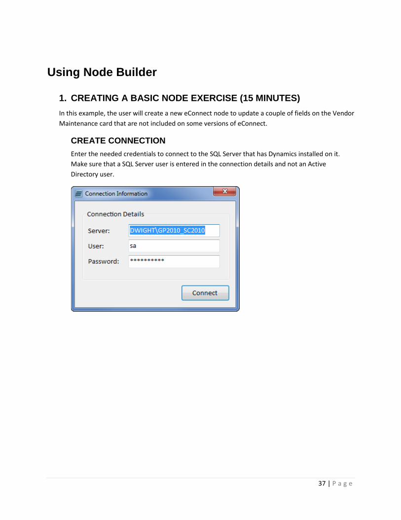
CREATE CONNECTION
Enter the needed credentials to connect to the SQL Server that has Dynamics installed on it.
Make sure that a SQL Server user is entered in the connection details and not an Active
Directory user.

38 | P a g e
CONFIGURE SETUP
On the setup screen, enter vendor1099 as the Node ID and Node Description, select “TWO” as
the default company database. For the procedure name, enter “Vendor1099” into the field.
When you tab off, it will put the “E1_” prefix onto the beginning of the procedure name if it is
not already there.
If SmartConnect is installed on this system, check the Create SmartConnect Node option. Select
“Payables” as the Node Group and “Vendors” as the Node Type in the Node Details section. For
the display name of the node, enter “Vendor 1099 Fields” or another name to be displayed
when using SmartConnect.
For the Companies list, check the companies that will have the procedure created in them when
the node is published. If registration keys have not been entered, the node will only be created
in Fabrikam, so for this example we will only select “Fabrikam, Inc. – TWO” as the destination
company.
39 | P a g e
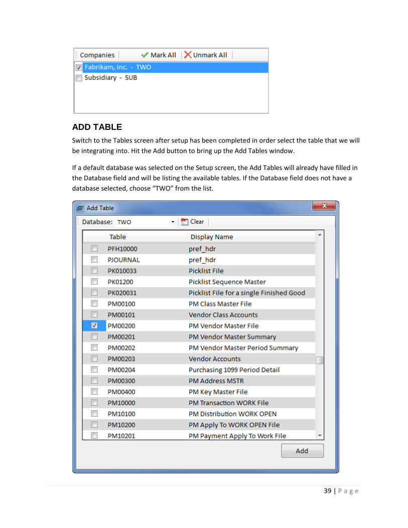
ADD TABLE
Switch to the Tables screen after setup has been completed in order select the table that we will
be integrating into. Hit the Add button to bring up the Add Tables window.
If a default database was selected on the Setup screen, the Add Tables will already have filled in
the Database field and will be listing the available tables. If the Database field does not have a
database selected, choose “TWO” from the list.
40 | P a g e
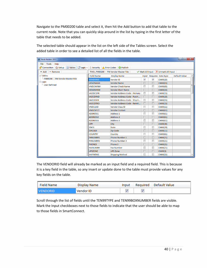
Navigate to the PM00200 table and select it, then hit the Add button to add that table to the
current node. Note that you can quickly skip around in the list by typing in the first letter of the
table that needs to be added.
The selected table should appear in the list on the left side of the Tables screen. Select the
added table in order to see a detailed list of all the fields in the table.
The VENDORID field will already be marked as an input field and a required field. This is because
it is a key field in the table, so any insert or update done to the table must provide values for any
key fields on the table.
Scroll through the list of fields until the TEN99TYPE and TEN99BOXNUMBER fields are visible.
Mark the Input checkboxes next to those fields to indicate that the user should be able to map
to those fields in SmartConnect.

41 | P a g e
The Display Names can also be changed on all fields if desired. The display names are what are
displayed in SmartConnect when mapping to those fields.
PUBLISH
Once the 1099 fields have been marked as input fields, the node can be created by hitting the
Publish button. Once again, if Node Builder is not registered then the nodes will only be created
inside of Fabrikam.
SMARTCONNECT
Once the node has been published, it will be available for mapping inside of SmartConnect.
Inside of GP go to Tools -> SmartConnect -> Map to open up the Map Setup window.
In the map setup window enter a map id and description, and then choose Payables as the node
group and Vendors as the node type. The custom node created in the above exercise, Vendor
1099 Fields, should be listed with the other nodes.
If we open up that node to map to it, we will see the 3 fields that were marked as input fields.
The Vendor ID will also be a required field since that was set in Node Builder and the two 1099
fields will use whatever display names were set.
42 | P a g e
2. CREATING AN ADVANCED NODE (60 MINUTES)
In this example, the user will create a node that integrates into vendor items and add logic to check
if the Vendor and the Item already exist. Additionally, the user will provide the option to update the
Purchasing UofM on the Item and include logic for this. There is a similar eConnect node that does
this particular integration, but the purpose of this example is to show how to use Node Builder and
the concepts in creating a node with familiar tables.
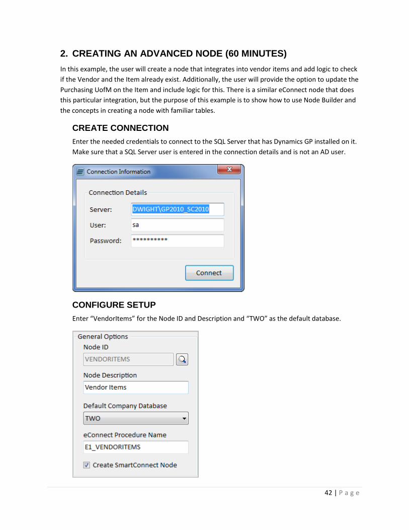
CREATE CONNECTION
Enter the needed credentials to connect to the SQL Server that has Dynamics GP installed on it.
Make sure that a SQL Server user is entered in the connection details and is not an AD user.
CONFIGURE SETUP
Enter “VendorItems” for the Node ID and Description and “TWO” as the default database.
43 | P a g e
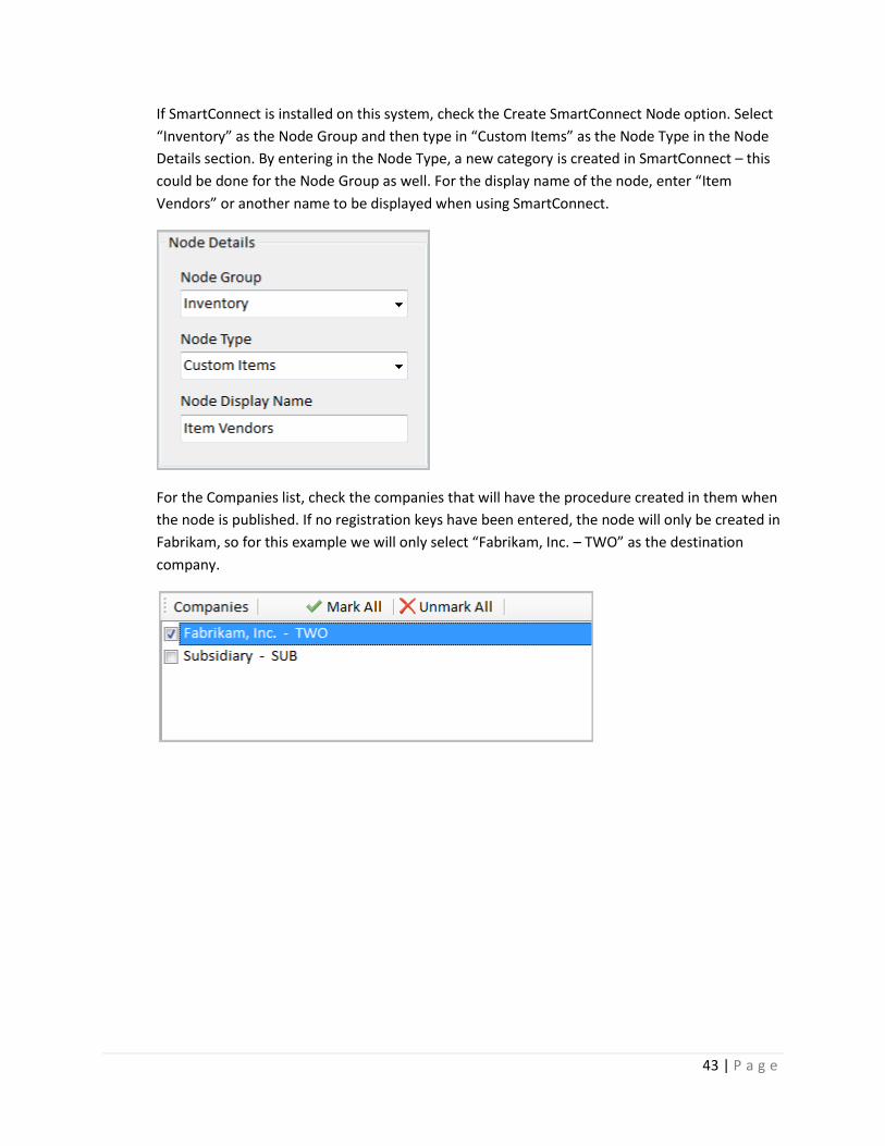
If SmartConnect is installed on this system, check the Create SmartConnect Node option. Select
“Inventory” as the Node Group and then type in “Custom Items” as the Node Type in the Node
Details section. By entering in the Node Type, a new category is created in SmartConnect – this
could be done for the Node Group as well. For the display name of the node, enter “Item
Vendors” or another name to be displayed when using SmartConnect.
For the Companies list, check the companies that will have the procedure created in them when
the node is published. If no registration keys have been entered, the node will only be created in
Fabrikam, so for this example we will only select “Fabrikam, Inc. – TWO” as the destination
company.
44 | P a g e
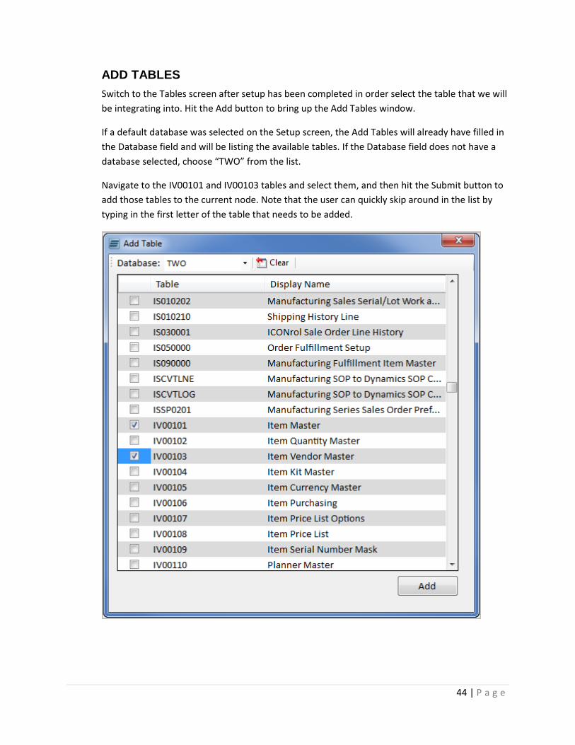
ADD TABLES
Switch to the Tables screen after setup has been completed in order select the table that we will
be integrating into. Hit the Add button to bring up the Add Tables window.
If a default database was selected on the Setup screen, the Add Tables will already have filled in
the Database field and will be listing the available tables. If the Database field does not have a
database selected, choose “TWO” from the list.
Navigate to the IV00101 and IV00103 tables and select them, and then hit the Submit button to
add those tables to the current node. Note that the user can quickly skip around in the list by
typing in the first letter of the table that needs to be added.
45 | P a g e
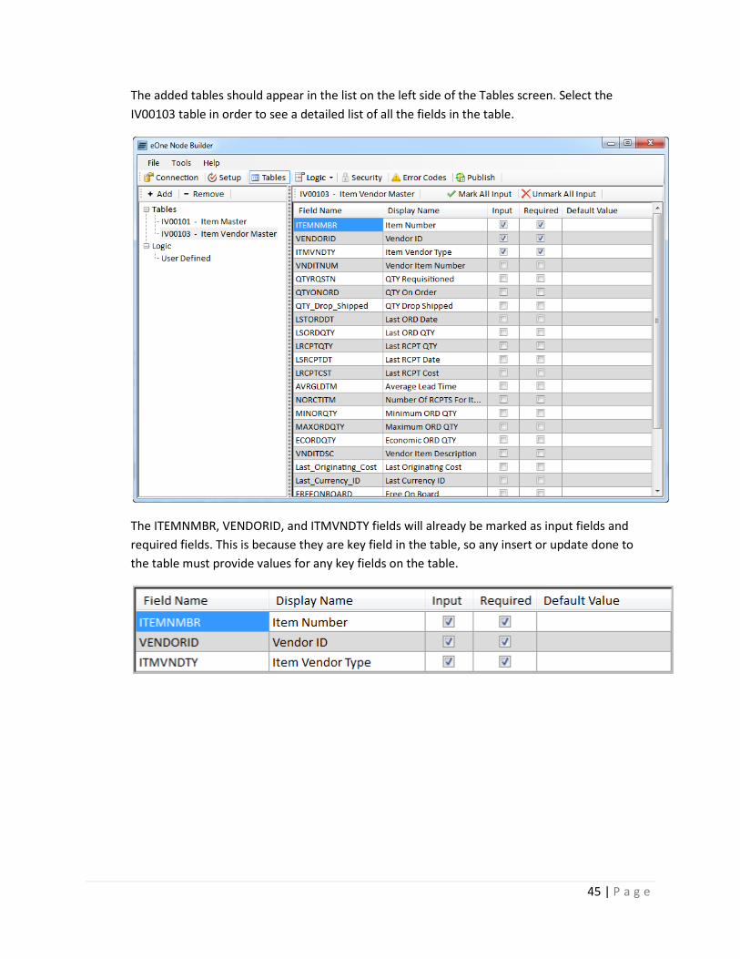
The added tables should appear in the list on the left side of the Tables screen. Select the
IV00103 table in order to see a detailed list of all the fields in the table.
The ITEMNMBR, VENDORID, and ITMVNDTY fields will already be marked as input fields and
required fields. This is because they are key field in the table, so any insert or update done to
the table must provide values for any key fields on the table.
46 | P a g e
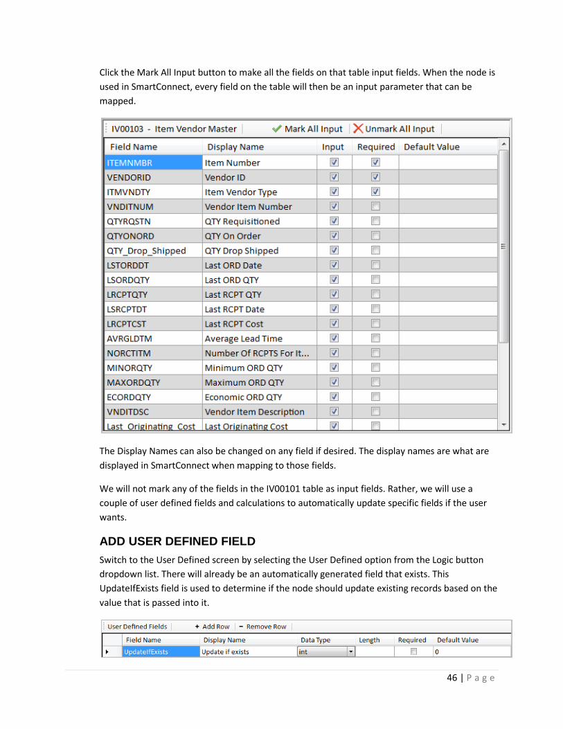
Click the Mark All Input button to make all the fields on that table input fields. When the node is
used in SmartConnect, every field on the table will then be an input parameter that can be
mapped.
The Display Names can also be changed on any field if desired. The display names are what are
displayed in SmartConnect when mapping to those fields.
We will not mark any of the fields in the IV00101 table as input fields. Rather, we will use a
couple of user defined fields and calculations to automatically update specific fields if the user
wants.
ADD USER DEFINED FIELD
Switch to the User Defined screen by selecting the User Defined option from the Logic button
dropdown list. There will already be an automatically generated field that exists. This
UpdateIfExists field is used to determine if the node should update existing records based on the
value that is passed into it.
47 | P a g e
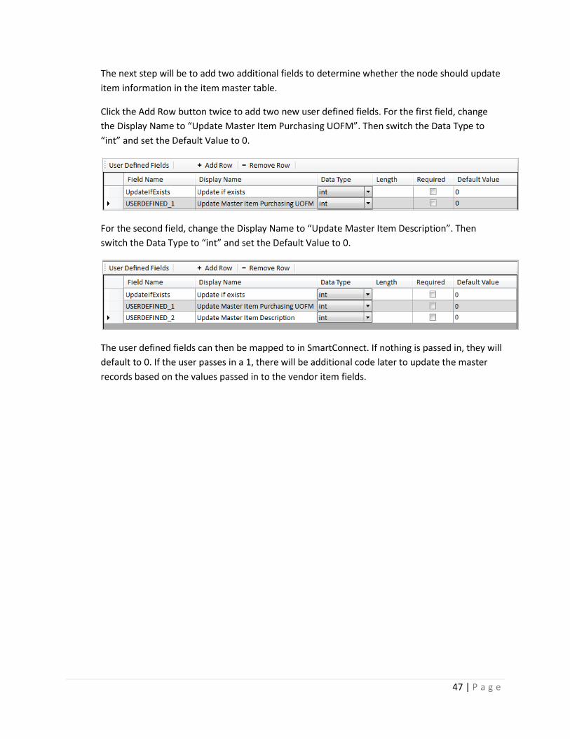
The next step will be to add two additional fields to determine whether the node should update
item information in the item master table.
Click the Add Row button twice to add two new user defined fields. For the first field, change
the Display Name to “Update Master Item Purchasing UOFM”. Then switch the Data Type to
“int” and set the Default Value to 0.
For the second field, change the Display Name to “Update Master Item Description”. Then
switch the Data Type to “int” and set the Default Value to 0.
The user defined fields can then be mapped to in SmartConnect. If nothing is passed in, they will
default to 0. If the user passes in a 1, there will be additional code later to update the master
records based on the values passed in to the vendor item fields.

48 | P a g e
ADD LOOKUP
Navigate to the Lookups screen by clicking on the Logic button and then selecting the Logic
option after the tables have been added so that a couple custom lookups can be created to
ensure the data being passed in is valid. In this section we will show how to create a lookup and
also use the built-in Lookup Templates.
When the Lookups screen is displayed, there will already be existing lookups. A lookup is
automatically created for each table that is added in order to check for existing records.
49 | P a g e
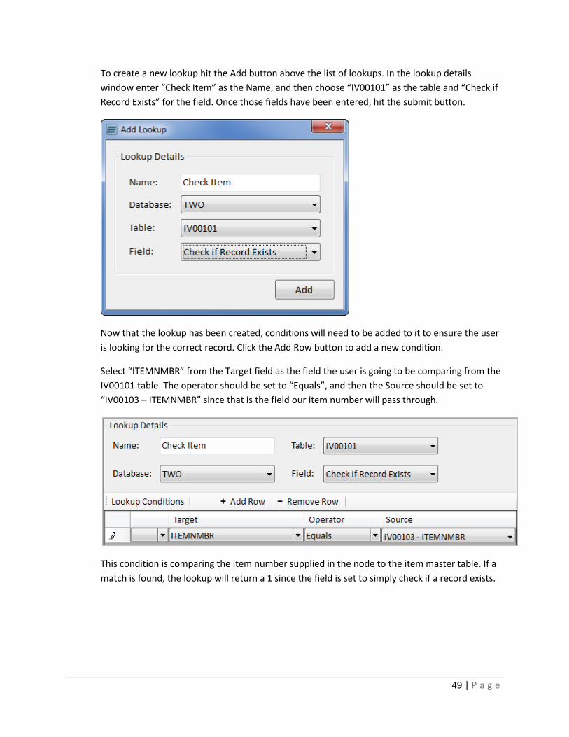
To create a new lookup hit the Add button above the list of lookups. In the lookup details
window enter “Check Item” as the Name, and then choose “IV00101” as the table and “Check if
Record Exists” for the field. Once those fields have been entered, hit the submit button.
Now that the lookup has been created, conditions will need to be added to it to ensure the user
is looking for the correct record. Click the Add Row button to add a new condition.
Select “ITEMNMBR” from the Target field as the field the user is going to be comparing from the
IV00101 table. The operator should be set to “Equals”, and then the Source should be set to
“IV00103 – ITEMNMBR” since that is the field our item number will pass through.
This condition is comparing the item number supplied in the node to the item master table. If a
match is found, the lookup will return a 1 since the field is set to simply check if a record exists.
50 | P a g e
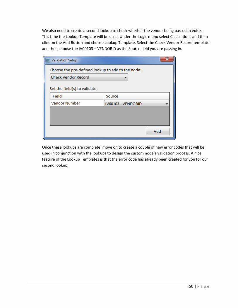
We also need to create a second lookup to check whether the vendor being passed in exists.
This time the Lookup Template will be used. Under the Logic menu select Calculations and then
click on the Add Button and choose Lookup Template. Select the Check Vendor Record template
and then choose the IV00103 – VENDORID as the Source field you are passing in.
Once these lookups are complete, move on to create a couple of new error codes that will be
used in conjunction with the lookups to design the custom node’s validation process. A nice
feature of the Lookup Templates is that the error code has already been created for you for our
second lookup.

51 | P a g e
ADD ERROR CODE
Click on the Error Codes button to hop to the next screen. There should be four error codes in
the grid already. The first three error codes are automatically generated and returned by the
node if a record is found and the node isn’t set to update existing records or there are errors in
the Pre or Post procedures. The fourth error code was created by the Lookup Template.
The next step is to add the last error code. The next code number in the toolbar can be changed
if desired. This number just sets the next error code number if available. For this example,
change it to 57500.
After that, click the Add Row button to add a new entry that we will enter an error description
into. For the description, enter “The Item Number passed in does not exist in the Item Master
table.” Then, double click on the Output Parameters field to open a new window where we can
select the output fields for this error.
52 | P a g e
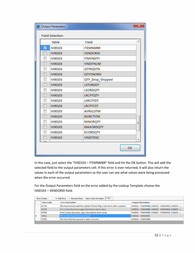
In this case, just select the “IV00103 – ITEMNMBR” field and hit the OK button. This will add the
selected field to the output parameters cell. If this error is ever returned, it will also return the
values in each of the output parameters so the user can see what values were being processed
when the error occurred.
For the Output Parameters field on the error added by the Lookup Template choose the
IV00103 – VENDORID field.
53 | P a g e
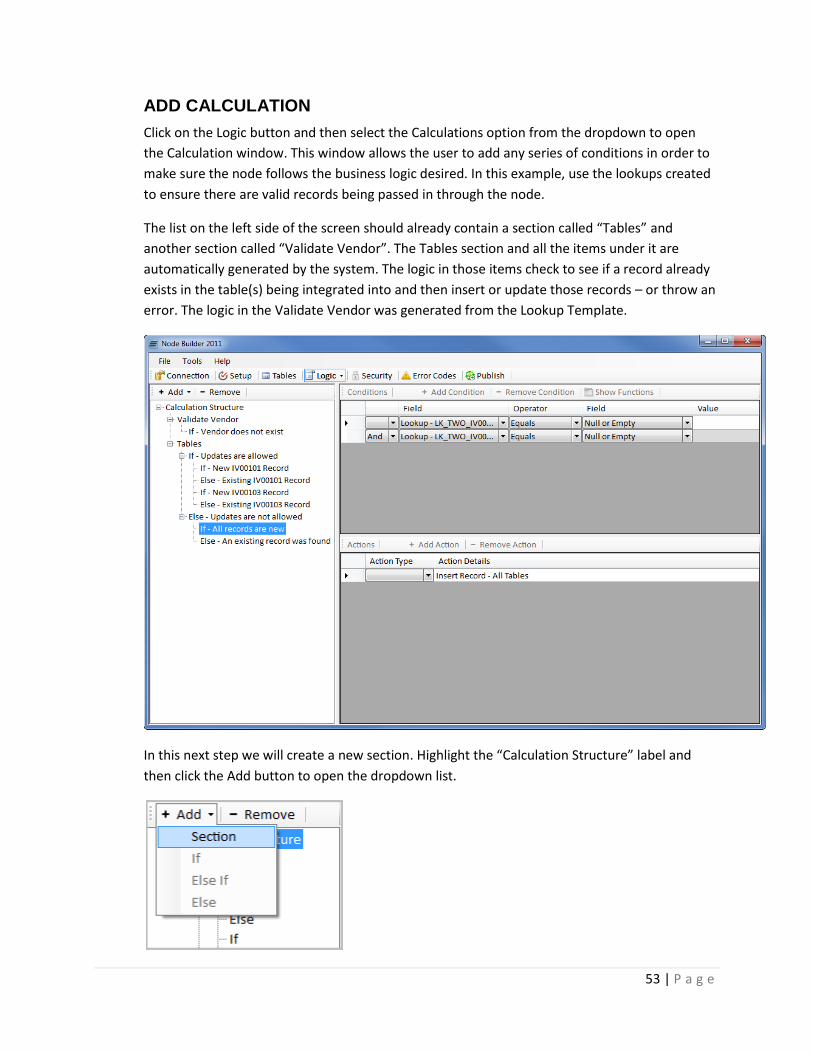
ADD CALCULATION
Click on the Logic button and then select the Calculations option from the dropdown to open
the Calculation window. This window allows the user to add any series of conditions in order to
make sure the node follows the business logic desired. In this example, use the lookups created
to ensure there are valid records being passed in through the node.
The list on the left side of the screen should already contain a section called “Tables” and
another section called “Validate Vendor”. The Tables section and all the items under it are
automatically generated by the system. The logic in those items check to see if a record already
exists in the table(s) being integrated into and then insert or update those records – or throw an
error. The logic in the Validate Vendor was generated from the Lookup Template.
In this next step we will create a new section. Highlight the “Calculation Structure” label and
then click the Add button to open the dropdown list.
54 | P a g e
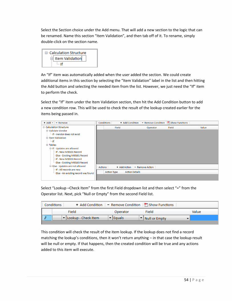
Select the Section choice under the Add menu. That will add a new section to the logic that can
be renamed. Name this section “Item Validation”, and then tab off of it. To rename, simply
double-click on the section name.
An “If” item was automatically added when the user added the section. We could create
additional items in this section by selecting the “Item Validation” label in the list and then hitting
the Add button and selecting the needed item from the list. However, we just need the “If” item
to perform the check.
Select the “If” item under the Item Validation section, then hit the Add Condition button to add
a new condition row. This will be used to check the result of the lookup created earlier for the
items being passed in.
Select “Lookup –Check Item” from the first Field dropdown list and then select “=” from the
Operator list. Next, pick “Null or Empty” from the second Field list.
This condition will check the result of the item lookup. If the lookup does not find a record
matching the lookup’s conditions, then it won’t return anything – in that case the lookup result
will be null or empty. If that happens, then the created condition will be true and any actions
added to this item will execute.
55 | P a g e
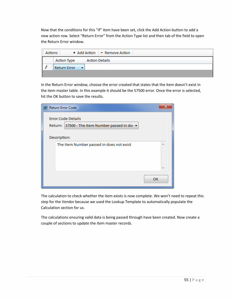
Now that the conditions for this “If” item have been set, click the Add Action button to add a
new action row. Select “Return Error” from the Action Type list and then tab of the field to open
the Return Error window.
In the Return Error window, choose the error created that states that the item doesn’t exist in
the item master table. In this example it should be the 57500 error. Once the error is selected,
hit the OK button to save the results.
The calculation to check whether the item exists is now complete. We won’t need to repeat this
step for the Vendor because we used the Lookup Template to automatically populate the
Calculation section for us.
The calculations ensuring valid data is being passed through have been created. Now create a
couple of sections to update the item master records.
56 | P a g e
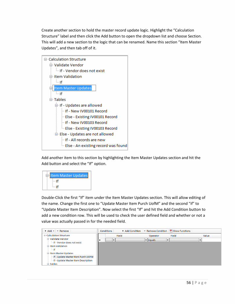
Create another section to hold the master record update logic. Highlight the “Calculation
Structure” label and then click the Add button to open the dropdown list and choose Section.
This will add a new section to the logic that can be renamed. Name this section “Item Master
Updates”, and then tab off of it.
Add another item to this section by highlighting the Item Master Updates section and hit the
Add button and select the “If” option.
Double-Click the first “If” item under the Item Master Updates section. This will allow editing of
the name. Change the first one to “Update Master Item Purch UofM” and the second “if” to
“Update Master Item Description”. Now select the first “If” and hit the Add Condition button to
add a new condition row. This will be used to check the user defined field and whether or not a
value was actually passed in for the needed field.
57 | P a g e
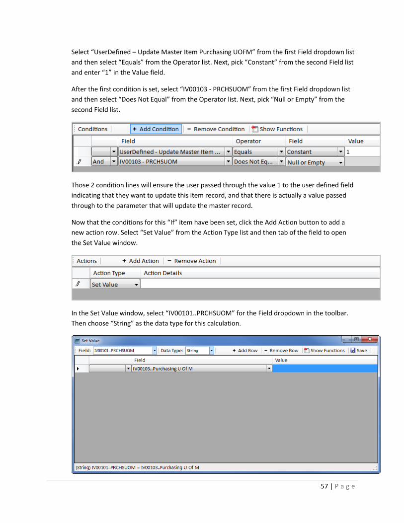
Select “UserDefined – Update Master Item Purchasing UOFM” from the first Field dropdown list
and then select “Equals” from the Operator list. Next, pick “Constant” from the second Field list
and enter “1” in the Value field.
After the first condition is set, select “IV00103 - PRCHSUOM” from the first Field dropdown list
and then select “Does Not Equal” from the Operator list. Next, pick “Null or Empty” from the
second Field list.
Those 2 condition lines will ensure the user passed through the value 1 to the user defined field
indicating that they want to update this item record, and that there is actually a value passed
through to the parameter that will update the master record.
Now that the conditions for this “If” item have been set, click the Add Action button to add a
new action row. Select “Set Value” from the Action Type list and then tab of the field to open
the Set Value window.
In the Set Value window, select “IV00101..PRCHSUOM” for the Field dropdown in the toolbar.
Then choose “String” as the data type for this calculation.

58 | P a g e
In the first row of the grid select “IV00103..Purchasing U Of M” for the Field cell and tab off of it.
The status bar should show what the calculation will be performing when it runs. In this case,
the user is simply setting the unit of measure parameter for the item master record equal to
what was passed in for the purchasing unit of measure on the vendor item.
Once that is set, hit the save button to return to the calculation screen. The new set value
calculation will be displayed in the Action Details field and that cell can be double-clicked if any
changes are needed.
Now do the same steps for the item description as well. Select the second “If” item under the
Item Master Updates section. Then hit the Add Condition button to add a new condition row.
This is used to check the user defined field and determine whether or not a value was actually
passed in for the needed field.
Select “UserDefined – Update Master Item Description” from the first Field dropdown list and
then select “Equals” from the Operator list. Next, pick “Constant” from the second Field list and
enter “1” in the Value field.
After the first condition is set, select “IV00103 - VNDITDSC” from the first Field dropdown list
and then select “Does Not Equal” from the Operator list. Next, pick “Null or Empty” from the
second Field list.
Now that the conditions for this “If” item have been set, click the Add Action button to add a
new action row. Select “Set Value” from the Action Type list and then tab of the field to open
the Set Value window.
In the Set Value window, select “IV00101..ITEMDESC” for the Field dropdown in the toolbar.
Then choose “String” as the data type for this calculation.
59 | P a g e
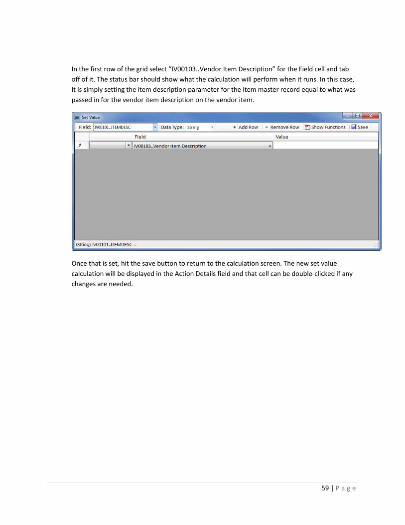
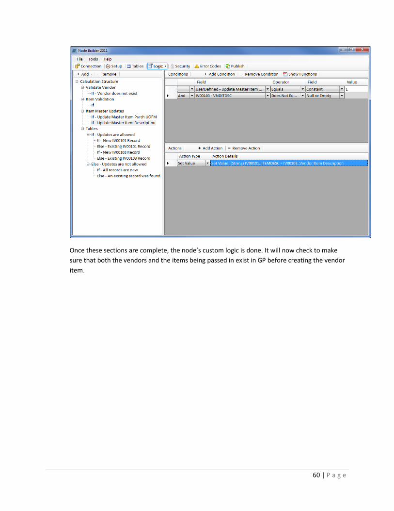
In the first row of the grid select “IV00103..Vendor Item Description” for the Field cell and tab
off of it. The status bar should show what the calculation will perform when it runs. In this case,
it is simply setting the item description parameter for the item master record equal to what was
passed in for the vendor item description on the vendor item.
Once that is set, hit the save button to return to the calculation screen. The new set value
calculation will be displayed in the Action Details field and that cell can be double-clicked if any
changes are needed.
60 | P a g e
Once these sections are complete, the node’s custom logic is done. It will now check to make
sure that both the vendors and the items being passed in exist in GP before creating the vendor
item.
61 | P a g e
PUBLISH
Now that we have added the table and created custom logic, hit the Publish button to create
the eConnect node on the SQL Server and create an entry in SmartConnect. Once again, if Node
Builder is not registered the nodes will only be created inside of Fabrikam.
SMARTCONNECT
Once the node has been published, it will be available for mapping inside of SmartConnect.
Inside of GP go to Tools -> SmartConnect -> Map to open up the Map Setup window.
In the map setup window enter a map id and description, and then choose Inventory as the
node group and Custom Items as the node type – the node type created in the exercise. The
custom node created, Item Vendors, should be displayed in the nodes list.
If the node is opened to map to it, all the fields that were marked as input fields can be seen.
Any fields that were marked as required should also be shown in red.
To test the logic, try to pass through a bad vendor id or item number that does not exist. The
custom logic will catch it and throw the appropriate error that was created.