non-rotating nfpa interchangeable cylinder line asset library/numatics-series-f-nfpa... ·...
TRANSCRIPT

F SeriesNon-Rotating NFPA Interchangeable Cylinder Line
w w w . n u m a t i c s . c o m
F Series Features and Benefits 3 Standard Mounts 4 How to Order 5 Dimensions 6-11 Basic No-Mount 6 Tooling Plate 6 Flange Mounts 7 Clevis Mounts 8 Eye Mounts 9 Side Lug Mount 10 Bottom Tap Mount 10 Extended Tie Rod Mount 11 Double Rod End 11 F Series Case Loads 12 F Series Switch Information 13 Sensing Part Number 14-16 Quick Disconnect Cable 17 Wiring Diagram 18 How to Order - F Series Piston Rod Assembly 19 How to Order - F Series Repair Kit 20 How to Order - F Series Seal Kit 20 Piston Rod Assembly Kit Removal/Installation Instructions 21 Repair and Seal Kit Removal/Installation Instructions 22 Diagrams 23 Seal Installation Guide 24
Table of Contents

Information subject to change without notice. For ordering information or regarding your local sales office visit www.numatics.com.3
FSERIES
The F Series is a Non-Rotating NFPA Interchangeable pneumatic cylinder line that provides the solution to specific applications where piston rotation is not acceptable. Our innovative dual rod design provides precision positioning and linear movement. This makes the F Series ideal for a multitude of high-tech applications.
TubeThe tube is hard coat anodized. The hard coating is an electro-chemical process which produces a very dense surface of aluminum oxide. This surface has extreme hardness (60 RC.), excellent wear and corrosion resistance, and a low coefficient of friction. Additionally, profile tubing is standard on 1-1/2” through 2-1/2” bore sizes (3-1/4” and 4” bores are the tie rod construction).
End CapsThe end caps are accurately machined from (6061-T6) solid aluminum bar stock. They are anodized for corrosion resistance. Additionally, a recess on the piston-mating surface (at both ends) enables the air to work on a larger piston area for effortless breakaway.
Rod BushingThe F Series includes a graphite filled, cast iron rod bushing that is extra long in length. Graphite filling offers the best bearing surface when using a hard chrome plated piston rod. Cast iron provides maximum resistance against wear. The added length adds superior alignment and support of the piston rod as well as provides maximum load bearing support.
Rod Seal and WiperThe unique rod seal and wiper combination is made with carboxilated nitrile with PTFE compound and is self-lubricating and durable. The rounded lip design ensures proper sealing and long life.
Piston RodHigh strength steel (100,000 psi minimum yield) piston rod has a ground, polished, and chrome plated surface. This surface provides maximum life for both the rod bushing and the seals.
Retaining PlateThe steel retaining plate has dual functions. It retains the bushing as well as inhibits rod rotation. Precise tolerances on both the bushing and the retaining plate allows for a exact fit which prevents rod rotation. By simply removing the four countersunk screws that maintain exact alignment, the orientation of the piston rod and tooling plate can be rotated 90° without cylinder disassembly.
Tooling PlateThe tooling plate is machined from solid steel. The tooling plate is reversible, offering both a flush or concentric mount.
Piston SealThe piston seal is a carboxilated nitrile with PTFE compound for self-lubricating. The “T” seal with back-up ring construction prevents rolling and seals at all pressures.
Wear BandThe wear band is a stable, lubricating strip located on the piston. We separated the load bearing points by locating the wear band at the rear of the piston. This maximizes column strength at full extension.
PistonThe solid aluminum alloy piston is strong and durable.
Cushion SealThe floating cushion seal design enables rapid stroke reversal by providing instantaneous full flow to the piston. Each cushion has a flush, retained adjustment needle.
Tube End SealThe tube end seals are compression type and reusable.
PortsOur enhanced port design enables the cylinder to work more efficiently. Through the use of precise machining depths and tool shape, we are able to smooth the flow path into and out of the cylinder.
Standard Specifications:• Meets NFPA specifications• Bore sizes from 1-1/2” through 4”• Piston rod diameters from 5/16” to 3/4”• Maximum pressure rating is 250 psi air • Standard temperature -10°F to 165°F (-23°C to 74°C)• All aluminum construction, except retaining plate and tooling plate
(steel)• NPTF ports• Flexible port and cushion locations

Information subject to change without notice. For ordering information or regarding your local sales office visit www.numatics.com.4
FSERIES
Standard F Series MountsCenterline Mounts
Pivot Mounts
Foot Mounts
DA MountDouble Rod End
F1 MountHead Rectangular Flange
P1 MountFixed Clevis
P2 MountDetachable Clevis
P3 MountFixed Eye
P4 MountDetachable Eye
F2 MountCap Rectangular Flange
S2 MountSide Lugs
S4 MountBottom Tapped
X0 MountBasic No Mount
X2 MountExtended Tie Rods – Cap End
*F Series are profile tube from 1 1/2" - 3 1/4" bore. Only 4" bore is round tube and tie rod.

Information subject to change without notice. For ordering information or regarding your local sales office visit www.numatics.com.5
FSERIES
How to Order
2**
1*
4
3
PORT AND CUSHION ORIENTATION
*PORTS NORMALLY IN POSITION 1**CUSHIONS NORMALLY IN POSITION 2 VERTICAL
STANDARD ROD ORIENTATION
3
4 2
CYLINDER AND ROD ORIENTATION
1*
OPTIONAL ROD ORIENTATIONHORIZONTAL
4
1*
2
3
MountingF1 = Front FlangeF2 = Rear FlangeP1 = Fixed ClevisP2 = Detachable ClevisP3 = Fixed EyeP4 = Detachable EyeS2 = Side Lug MountS4 = Bottom TappedX0 = Basic No MountX2 = Cap Extended Tie Rods
TypeF = F Series Non-Rotating
NFPA Interchangeable
BoreK 1-1/2"L 2"M 2-1/2"P 3-1/4"R
===== 4"
Full Inch of Stroke00 = 0" Stroke01 = 1" Stroke02 = 2" Stroke03 = 3" Stroke20 = 20" Stroke
Fractional Inches of StrokeA 0" I 1/2"B 1/16" J 9/16"C 1/8" K 5/8"D 3/16" L 11/16"E 1/4" M 3/4"F 5/16" N 13/16"G 3/8" O 7/8"H
======== 7/16" P
======== 15/16"
F1 F K 00 A 1 P C AA 0
Magnet0 No Magnet2
== Magnet
OptionsAA = No OptionsBA** = Bumpers Both Ends (3-1/4" and 4" only)BH** = Bumper Head only (3-1/4" and 4" only)BC** = Bumper Cap onlyKA* Stroke AdjusterDA = Double Rod EndNA = Nickel Plated Cylinder
Stainless Steel Rod and Tie rodsRA* = Save Air Stroke AdjusterSA = Stainless Steel Piston RodSS = Stainless Piston Rod and Tie RodST = Stainless Tie Rods1A* = Rod Extension4A* = Stop Tube* Specify length.**Bumpers add 0.062" to OAL (per bumper).
CushionsPosition 1 2 3 4No Cushion A A A AHead and Cap B C D EHead Only F G H JCap Only K L M N
PortsPosition 1/8" 1/4" 3/8" 1/2" 3/4"
1 C D E F 2 I K 3 O Q4
B H NT U
JPV W
LRX
Rod End Codes1 Rod Vertical, Style # 1 on opposite
end if the DA option is used2 Rod Vertical, Style # 2 on opposite
end if the DA option is used3 Rod Vertical, Style # 3 on opposite
end if the DA option is used6 Rod Horizontal, Style # 1 on opposite
end if the DA option is used7 Rod Horizontal, Style # 2 on opposite
end if the DA option is used8
=
=
=
=
=
= Rod Horizontal, Style # 3 on oppositeend if the DA option is used
--
Port and Cushion Orientation Cylinder Rod Orientation
* Ports Normally In Position 1** Cushions Normally In Position 2
Standard Rod Orientation Vertical
Optional RodOrientation Horizontal

Information subject to change without notice. For ordering information or regarding your local sales office visit www.numatics.com.6
FSERIES
AR SQ.
E SQ.
Ø ROD
Y P + STROKE
2X EE NPTF
G
R
LAF
LB + STROKE
ZB + STROKE
J
K
C F
WF
B
NFPA Mount Code MX0
NOTE: Tooling plate removed for clarity.
Basic No Mount Cylinder
Dimensions: Inches
Bore Rod A B C E F G J K P R Y EE LB WF ZB LAF
1-1/2" 0.313 1.000 0.640 0.500 2.000 0.375 1.500 1.000 0.250 2.250 1.430 2.813 3/8 3.625 0.875 5.750 1.875
2" 0.500 1.000 0.844 0.500 2.500 0.375 1.500 1.000 0.313 2.250 1.840 2.813 3/8 3.625 0.875 5.813 1.875
2-1/2" 0.625 1.250 1.219 0.500 3.000 0.375 1.500 1.000 0.313 2.375 2.190 3.063 3/8 3.750 .875 6.188 2.125
3-1/4" 0.750 1.250 1.219 0.500 3.750 0.625 1.750 1.250 0.375 2.625 2.760 3.438 3/8 4.250 1.125 7.000 2.375
4" 0.750 1.250 1.907 0.500 4.500 0.625 1.750 1.250 0.375 2.625 3.320 3.438 1/2 4.250 1.125 7.000 2.375
Bore CC FF GG KK H TS TT
1-1/2" 5/16-18 0.375 0.860 #10-32 0.625 1.500 1.120
2" 5/16-18 0.375 1.180 1/4-28 0.750 2.000 1.430
2-1/2" 3/8-16 0.625 1.500 5/16-24 0.875 2.500 1.840
3-1/4" 1/2-13 0.625 1.970 3/8-24 0.875 3.250 1.790
4" 1/2-13 0.625 2.760 3/8-24 0.875 4.000 3.440
AGG
TT SQ.
TS SQ.
4X KK TAP x H DEEP
2X CC TAP x FF DEEP
Tooling Plate
Information subject to change without notice. For ordering information or regarding your local sales office visit www.numatics.com.7
FSERIES
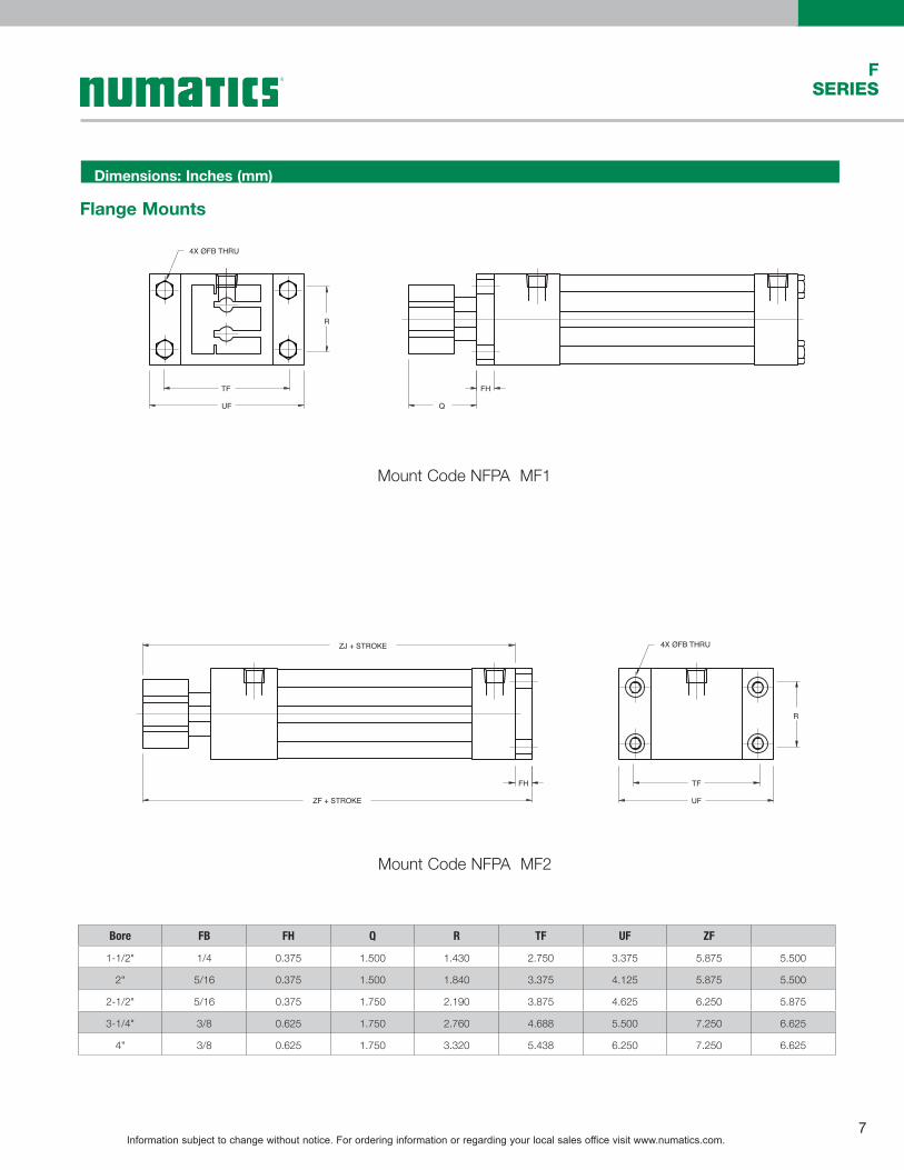
Flange Mounts
4X ØFB THRU
TF
UF
R
Q
FH
R
UF
TFFH
4X ØFB THRUZJ + STROKE
ZF + STROKE
Mount Code NFPA MF1
Mount Code NFPA MF2
Dimensions: Inches (mm)
Bore FB FH Q R TF UF ZF
1-1/2" 1/4 0.375 1.500 1.430 2.750 3.375 5.875 5.500
2" 5/16 0.375 1.500 1.840 3.375 4.125 5.875 5.500
2-1/2" 5/16 0.375 1.750 2.190 3.875 4.625 6.250 5.875
3-1/4" 3/8 0.625 1.750 2.760 4.688 5.500 7.250 6.625
4" 3/8 0.625 1.750 3.320 5.438 6.250 7.250 6.625
Information subject to change without notice. For ordering information or regarding your local sales office visit www.numatics.com.8
FSERIES
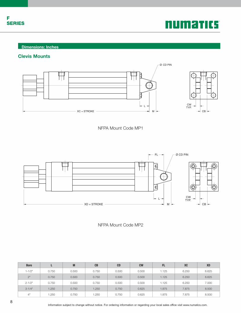
Ø CD PIN
L
MXC + STROKE
CWTYP.
CB
NFPA Mount Code MP1
NFPA Mount Code MP2
Ø CD PIN
L
MXD + STROKE
CWTYP.
CB
FL
Clevis Mounts
Dimensions: Inches
Bore L M CB CD CW FL XC XD
1-1/2" 0.750 0.500 0.750 0.500 0.500 1.125 6.250 6.625
2" 0.750 0.500 0.750 0.500 0.500 1.125 6.250 6.625
2-1/2" 0.750 0.500 0.750 0.500 0.500 1.125 6.250 7.000
3-1/4" 1.250 0.750 1.250 0.750 0.625 1.875 7.875 8.500
4" 1.250 0.750 1.250 0.750 0.625 1.875 7.875 8.500

Information subject to change without notice. For ordering information or regarding your local sales office visit www.numatics.com.9
FSERIES
Eye Mounts
Ø CD PIN
L
MXC + STROKE CB
NFPA Mount Code MP3
NFPA Mount Code MP4
Ø CD PIN
L
MXD + STROKE
CB
FL
Dimensions: Inches
Bore L M CB CD FL XC XD
1-1/2" 0.750 0.500 0.750 0.500 1.125 6.250 6.625
2" 0.750 0.500 0.750 0.500 1.125 6.250 6.625
2-1/2" 0.750 0.500 0.750 0.500 1.125 6.250 7.000
3-1/4" 1.250 0.750 1.250 0.750 1.875 7.875 8.500
4" 1.250 0.750 1.250 0.750 1.875 7.875 8.500
Information subject to change without notice. For ordering information or regarding your local sales office visit www.numatics.com.10
FSERIES
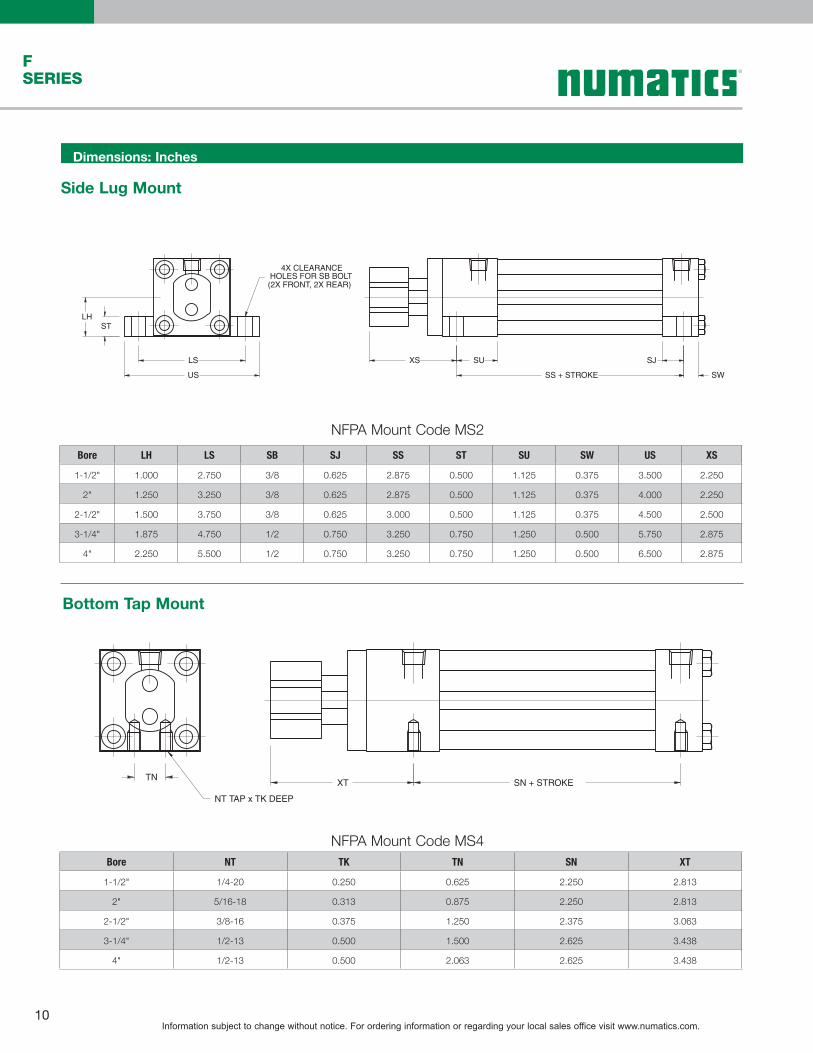
4X CLEARANCEHOLES FOR SB BOLT(2X FRONT, 2X REAR)
LS
US
LHST
SS + STROKE
SUXS
SW
SJ
SN + STROKE
NT TAP x TK DEEP
TNXT
Bottom Tap Mount
NFPA Mount Code MS4
NFPA Mount Code MS2
Side Lug Mount
Dimensions: Inches
Bore LH LS SB SJ SS ST SU SW US XS
1-1/2" 1.000 2.750 3/8 0.625 2.875 0.500 1.125 0.375 3.500 2.250
2" 1.250 3.250 3/8 0.625 2.875 0.500 1.125 0.375 4.000 2.250
2-1/2" 1.500 3.750 3/8 0.625 3.000 0.500 1.125 0.375 4.500 2.500
3-1/4" 1.875 4.750 1/2 0.750 3.250 0.750 1.250 0.500 5.750 2.875
4" 2.250 5.500 1/2 0.750 3.250 0.750 1.250 0.500 6.500 2.875
Bore NT TK TN SN XT
1-1/2" 1/4-20 0.250 0.625 2.250 2.813
2" 5/16-18 0.313 0.875 2.250 2.813
2-1/2" 3/8-16 0.375 1.250 2.375 3.063
3-1/4" 1/2-13 0.500 1.500 2.625 3.438
4" 1/2-13 0.500 2.063 2.625 3.438

Information subject to change without notice. For ordering information or regarding your local sales office visit www.numatics.com.11
FSERIES
ZJ + STROKE BB R SQ.
DD
Extended Tie Rod Mount
NFPA Mount Code MX2
AR SQ.E SQ.
Ø RODY P + STROKE
2X EE NPTF
GTYP.LAF
LD + STROKEZM + STROKE
F
LAF
C F
WF
B
SF + STROKE
SDWRENCH FLATS
SKTHREADS
Ø SM
SASC
Double Rod End
Note: For switch ordering information see the Actuator Accessories section.
Order as “DA” OptionBore Rod A B C E EE F G LD LAF P
1-1/2” 0.313 1.000 0.640 0.500 2.000 3/8 0.375 1.500 4.125 1.875 2.250
2” 0.500 1.000 0.844 0.500 2.500 3/8 0.375 1.500 4.125 1.875 2.250
2-1/2” 0.625 1.250 1.219 0.500 3.000 3/8 0.375 1.500 4.250 2.125 2.375
3-1/4” 0.750 1.250 1.129 0.500 3.750 3/8 0.625 1.750 4.750 2.375 2.625
4” 0.750 1.250 1.907 0.500 4.500 1/2 0.625 1.750 4.750 2.375 2.625
Bore R SA SC SD SF SK SM WF Y ZM
1-1/2” 1.430 0.750 0.375 0.500 1.000 7/16-20 0.625 0.875 2.813 7.000
2” 1.840 0.750 0.375 0.500 1.000 7/16-20 0.625 0.875 2.813 7.000
2-1/2” 2.190 0.750 0.375 0.500 1.000 7/16-20 0.625 0.875 3.063 7.375
3-1/4” 2.760 1.125 0.500 0.813 1.375 3/4-16 1.000 1.125 3.438 8.500
4” 3.320 1.125 0.500 0.813 1.375 3/4-16 1.000 1.125 3.438 8.500
Dimensions: Inches
Bore BB DD R ZJ
1-1/2" 1.000 1/4-28 1.430 5.500
2" 1.125 5/16-24 1.840 5.500
2-1/2" 1.125 5/16-24 2.190 5.875
3-1/4" 1.375 3/8-24 2.760 6.625
4" 1.375 3/8-24 3.320 6.625
Information subject to change without notice. For ordering information or regarding your local sales office visit www.numatics.com.12
FSERIES
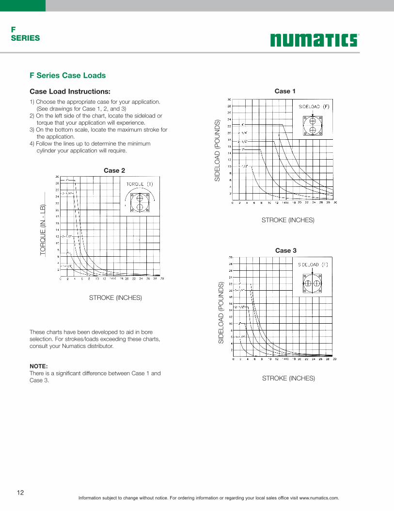
F Series Case Loads
Case Load Instructions:1) Choose the appropriate case for your application. (See drawings for Case 1, 2, and 3)2) On the left side of the chart, locate the sideload or torque that your application will experience.3) On the bottom scale, locate the maximum stroke for the application.4) Follow the lines up to determine the minimum cylinder your application will require.
Case 1
Case 2
STROKE (INCHES)
STROKE (INCHES)
TORQ
UE (I
N - L
B)
Case 3
STROKE (INCHES)
These charts have been developed to aid in bore selection. For strokes/loads exceeding these charts, consult your Numatics distributor.
NOTE:There is a significant difference between Case 1 and Case 3.
SIDE
LOAD
(PO
UNDS
)SI
DELO
AD (P
OUN
DS)

Information subject to change without notice. For ordering information or regarding your local sales office visit www.numatics.com.13
FSERIES
P/N Switch StyleElectrical
DesignOutput
Operating Voltage
Current RatingSwitching
PowerVoltage
DropNEMA IP Rating
Temperature Rating
SR6-002 Flying Lead AC/DC REED Normally Open 5 -120 VAC/DC 0.025 Amps Max.0.001 Amps Min. 3 Watts Max. 3.5 Volts NEMA 6 -25º to +75º C
SR6-004 Flying Lead AC/DC REED Normally Open 5 -120 VAC/DC 0.5 Amps Max.0.005 Amps Min. 10 Watts Max. 3.0 Volts NEMA 6 -25º to +75º C
SR6-022 M8 Connector AC/DC REED Normally Open 5-50 VAC 5-60 VDC
0.025 Amps Max.0.001 Amps Min. 12 Watts Max. 0.5 Volts NEMA 6 -25º to +75º C
SR6-024 M8 Connector AC/DC REED Normally Open 5-50 VAC5-60 VDC
0.5 Amps Max.0.005 Amps Min. 10 Watts Max. 3.0 Volts NEMA 6 -25º to +75º C
.921
.559
.531
.433
.921
.559
.531
.433
Reed Switch - Normally Open Type SR6
F Series Switch InformationF Series World Switch Reed Switch Part Numbers
NFPA Interchangeable CylindersF Series (Tie Rod)
F Series (Profile Tube)
Sensor Description
Standard Cord Set
Quick Disconnect
Reed Switch REED-FL2-00 REED-QDS-M8U
Hall PNP PNP-FL2-00-U PNP-QDS-M8-U
Hall NPN NPN-FL2-00-U NPN-QDS-M8-U
Sensor Description
Standard Cord Set
Quick Disconnect
Reed Switch REED-FL2-00 REED-QDS-M8U
Hall PNP PNP-FL2-00-U PNP-QDS-M8-U
Hall NPN NPN-FL2-00-U NPN-QDS-M8-U
Bore Bracket P/N
1 1/2" N99-1181
2" N99-1182
2 1/2" N99-1182
3 1/4" N99-1183
4" N99-1183
5" N99-1184
6" N99-1184
8" N99-1184
10" N99-1191
12" N99-1191
14" N99-1200
Bore Bracket P/N
1 1/2" N99-1185
2" N99-1185
2 1/2" N99-1185
See page 13, 14, & 15 for sensor specifications
See page 13, 14, & 15 for sensor specifications

Information subject to change without notice. For ordering information or regarding your local sales office visit www.numatics.com.14
FSERIES
ELECTRICAL DESIGN DC PNP
OUTPUT Normally Open
OPERATING VOLTAGE 10-30 VDC
CURRENT RATING 100 mA
SHORT-CIRCUIT PROTECTION
Yes
OVERLOAD PROTECTION Yes
REVERSE POLARITY PROTECTION
Yes
VOLTAGE DROP < 2.5 V
CURRENT CONSUMPTION < 12 mA
REPEATABILITY < .2mm
POWER-ON DELAY TIME < 30 ms
SWITCH FREQUENCY > 3000 Hz
AMBIENT TEMPERATURE -25ºC to 85ºC
PROTECTION IP 67, III
HYSTERESIS 1.0mm
MAGNETIC SENSITIVITY 2.0 mT
TRAVEL SPEED > 10 m/s
HOUSING MATERIAL PA (Polyamide) Black; Fastening Clamp:Stainless Steel
FUNCTION DISPLAY SWITCHING STATUS
Yellow LED
CONNECTION Flying Leads, Pur Cable (2m Long, 3 x26 Gauge Wire)
REMARKSClamping Screw with Combined Slot/Hexagon
Socket Head AF 1.5cULus - Class 2 Source Required
ACCESSORIES Rubber Placehold, Cable Clip, and Cut SheetTo Be Provided with Every Switch
AGENCY APPROVALS
ELECTRICAL DESIGN DC PNP
OUTPUT Normally Open
OPERATING VOLTAGE 10-30 VDC
CURRENT RATING 100 mA
SHORT-CIRCUIT PROTECTION
Yes
OVERLOAD PROTECTION Yes
REVERSE POLARITY PROTECTION
Yes
VOLTAGE DROP < 2.5 V
CURRENT CONSUMPTION < 12 mA
REPEATABILITY < .2mm
POWER-ON DELAY TIME < 30 ms
SWITCH FREQUENCY > 3000 Hz
AMBIENT TEMPERATURE -25ºC to 85ºC
PROTECTION IP 67, III
HYSTERESIS 1.0mm
MAGNETIC SENSITIVITY 2.0 mT
TRAVEL SPEED > 10 m/s
HOUSING MATERIAL PA (Polyamide) Black; Fastening Clamp:Stainless Steel
FUNCTION DISPLAY SWITCHING STATUS
Yellow LED
CONNECTION M8 Connector (Snap Fit) , Pur Cable (.3 m)
REMARKSClamping Screw with Combined Slot/Hexagon
Socket Head AF 1.5cULus - Class 2 Source Required
ACCESSORIES Rubber Placehold, Cable Clip, and Cut SheetTo Be Provided with Every Switch
AGENCY APPROVALS
.98 [25.0]
.20 [5.0]
SENSING FACE
LED
P494A0022600A00
.25 [6.4]
.20 [5.1]
11.81 [300.0]
1.46 [37.0]
M8 x 1.0
PARTNUMBER
FASTENING CLAMP
.98 [25.0]
.20 [5.0]
FASTENING CLAMP
SENSING FACE
LED
P494A0022300A00
.25 [6.4]
.20 [5.1]PARTNUMBER
78.74 [2000.0]
1.50 [38.1]
BLUE (-)BLACK (OUTPUT) BROWN (+) 26 GAUGE WIRES
PNP-FL2-00-U PNP-QDS-M8-U
RoHS RoHS
Sensing Part Numbers
*Switches are not designed for wet environments. Please see your distributor for additional information.

Information subject to change without notice. For ordering information or regarding your local sales office visit www.numatics.com.15
FSERIES
*Switches are not designed for wet environments. Please see your distributor for additional information.
ELECTRICAL DESIGN DC NPN
OUTPUT Normally Open
OPERATING VOLTAGE 10-30 VDC
CURRENT RATING 100 mA
SHORT-CIRCUIT PROTECTION
Yes
OVERLOAD PROTECTION Yes
REVERSE POLARITY PROTECTION
Yes
VOLTAGE DROP < 2.5 V
CURRENT CONSUMPTION < 12 mA
REPEATABILITY < .2mm
POWER-ON DELAY TIME < 30 ms
SWITCH FREQUENCY > 3000 Hz
AMBIENT TEMPERATURE -25ºC to 85ºC
PROTECTION IP 67, III
HYSTERESIS 1.0mm
MAGNETIC SENSITIVITY 2.0 mT
TRAVEL SPEED > 10 m/s
HOUSING MATERIAL PA (Polyamide) Black; Fastening Clamp:Stainless Steel
FUNCTION DISPLAY SWITCHING STATUS
Yellow LED
CONNECTION M8 Connector (Snap Fit) , Pur Cable (.3 m)
REMARKSClamping Screw with Combined Slot/Hexagon
Socket Head AF 1.5cULus - Class 2 Source Required
ACCESSORIES Rubber Placehold, Cable Clip, and Cut SheetTo Be Provided with Every Switch
AGENCY APPROVALS
.98 [25.0]
.20 [5.0]
SENSING FACE
LED
P494A0022700A00
.25 [6.4]
.20 [5.1]
11.81 [300.0]
1.46 [37.0]
M8 x 1.0
PARTNUMBER
FASTENING CLAMP
ELECTRICAL DESIGN DC NPN
OUTPUT Normally Open
OPERATING VOLTAGE 10-30 VDC
CURRENT RATING 100 mA
SHORT-CIRCUIT PROTECTION
Yes
OVERLOAD PROTECTION Yes
REVERSE POLARITY PROTECTION
Yes
VOLTAGE DROP < 2.5 V
CURRENT CONSUMPTION < 12 mA
REPEATABILITY < .2mm
POWER-ON DELAY TIME < 30 ms
SWITCH FREQUENCY > 3000 Hz
AMBIENT TEMPERATURE -25ºC to 85ºC
PROTECTION IP 67, III
HYSTERESIS 1.0mm
MAGNETIC SENSITIVITY 2.0 mT
TRAVEL SPEED > 10 m/s
HOUSING MATERIAL PA (Polyamide) Black; Fastening Clamp:Stainless Steel
FUNCTION DISPLAY SWITCHING STATUS
Yellow LED
CONNECTION Flying Leads, Pur Cable (2m Long, 3 x26 Gauge Wire)
REMARKSClamping Screw with Combined Slot/Hexagon
Socket Head AF 1.5cULus - Class 2 Source Required
ACCESSORIES Rubber Placehold, Cable Clip, and Cut SheetTo Be Provided with Every Switch
AGENCY APPROVALS
.98 [25.0]
.20 [5.0]
SENSING FACE
LED
P494A0022400A00
.25 [6.4]
.20 [5.1]PART
NUMBER
78.74 [2000.0]
1.50 [38.1]
BLUE (-)BLACK (OUTPUT) BROWN (+) 26 GAUGE WIRES
FASTENING CLAMP
NPN-FL2-00-U NPN-QDS-M8-U
RoHS RoHS
Sensing Part Numbers

Information subject to change without notice. For ordering information or regarding your local sales office visit www.numatics.com.16
FSERIES
ELECTRICAL DESIGN AC/DC REED
OUTPUT Normally Open
OPERATING VOLTAGE 5-120 VAC/DC
CURRENT RATING 100 mA*
SHORT-CIRCUIT PROTECTION
No
OVERLOAD PROTECTION No
REVERSE POLARITY PROTECTION
Yes
VOLTAGE DROP < 5 V
REPEATABILITY ± .2mm
MAKETIME INCLUDING BOUNCE
< .6 ms
BREAKTIME < .1 ms
SWITCHING POWER (MAX) 5 W
SWITCH FREQUENCY 1000 Hz
AMBIENT TEMPERATURE -25ºC to 70ºC
PROTECTION IP 67, II
HYSTERESIS .9mm
HOUSING MATERIAL PA (Polyamide) Black; Fastening Clamp:Stainless Steel
FUNCTION DISPLAY SWITCHING STATUS
Yellow LED
CONNECTION Flying Leads, Pur Cable (2m Long, 2 x26 Gauge Wire)
REMARKS*External Protective Circuit for Inductive Load
(Valve, Contactor, Etc..) Necessary.Conforms to 2008 NEC Section 725 III,
Class 2 Circuits
Clamping Screw with Combined Slot/Hexagon Socket Head AF 1.5.
No LED Function in case of Polarity in DC Operation
ACCESSORIES Rubber Placehold, Cable Clip, and Cut SheetTo Be Provided with Every Switch
AGENCY APPROVALS
ELECTRICAL DESIGN AC/DC REED
OUTPUT Normally Open
OPERATING VOLTAGE *5-60 VDC / 5-50 VAC
CURRENT RATING 100 mA
SHORT-CIRCUIT PROTECTION
No
OVERLOAD PROTECTION No
REVERSE POLARITY PROTECTION
Yes
VOLTAGE DROP < 5 V
REPEATABILITY ± .2mm
MAKETIME INCLUDING BOUNCE
< .6 ms
BREAKTIME < .1 ms
SWITCHING POWER (MAX) 5 W
SWITCH FREQUENCY 1000 Hz
AMBIENT TEMPERATURE -25ºC to 70ºC
PROTECTION IP 67, II
HYSTERESIS .9mm
HOUSING MATERIAL PA (Polyamide) Black; Fastening Clamp:Stainless Steel
FUNCTION DISPLAY SWITCHING STATUS
Yellow LED
CONNECTIONM8 Connector (Snap Fit), Pur Cable (.3m)
REMARKS *External Protective Circuit for Inductive Load (Valve, Contactor, Etc..) Necessary.
Conforms to 2008 NEC Section 725 III, Class 2 Circuits
M8 Connector voltage limited to 5-60 vdc / 5-50 vac to conform with 2008 IEC 61076-2-104
Clamping Screw with Combined Slot/Hexagon Socket Head AF 1.5.
No LED Function in case of Polarity in DC Operation
ACCESSORIES Rubber Placehold, Cable Clip, and Cut SheetTo Be Provided with Every Switch
AGENCY APPROVALS
.25 [6.4]
.20 [5.1]
11.81 [300.0]
1.46 [37.0]
M8 x 1.0
1.20 [30.5]
.20 [5.0]
LED
P494A0021600A00
T AA
0809
PARTNUMBER
.22 [5.7]
FASTENING CLAMP
.25 [6.4]
.20 [5.1]
1.20 [30.5]
.20 [5.0]
LED
P494A0021300A00
T AA
0809
PARTNUMBER
.22 [5.7]
FASTENING CLAMP
78.74 [2000.0]
1.50 [38.1]
BLUE (-)BROWN (+) 26 GAUGE WIRES
REED-FL2-00 REED-QDS-M8U
RoHS RoHS
Sensing Part Numbers
*Switches are not designed for wet environments. Please see your distributor for additional information.

Information subject to change without notice. For ordering information or regarding your local sales office visit www.numatics.com.17
FSERIES
P/N Switch StyleElectrical
DesignOutput
Operating Voltage
Current RatingSwitching
PowerVoltage
DropNEMA IP Rating
Temperature Rating
SH6-031 Flying Lead PNP Normally Open 6-24 VDC 0.3 Amps Max. 3 Watts Max. 3.5 Volts NEMA 6 -25º to +75º C
SH6-032 Flying Lead NPN Normally Open 6-24 VDC 0.3 Amps Max. 10 Watts Max. 3.0 Volts NEMA 6 -25º to +75º C
SH6-021 M8 Connector PNP Normally Open 6-24 VDC 0.3 Amps Max. 12 Watts Max. 0.5 Volts NEMA 6 -25º to +75º C
SH6-022 M8 Connector NPN Normally Open 6-24 VDC 0.3 Amps Max. 10 Watts Max. 3.0 Volts NEMA 6 -25º to +75º C
F Series World Switch Hall Effect Part Numbers
F Series 9000 Application Detail1
2
3
Profile Tube Detail1. 9000 Switch2. Included Dovetail adapter3. Dove Tail extrusion
F series 9000 Series SwitchCylinders Bore Part Number
F series Profile 1 1/2”-2 1/2” Bore Direct Fit w/included adapter
.921
.559
.531
.433
.921
.559
.531
.433
PNP Sourcing NPN Sinking

Information subject to change without notice. For ordering information or regarding your local sales office visit www.numatics.com.18
FSERIES
FemaleConnector
MaleConnector
1 13 3
4 4 11.0
6.04.0
Ø 2.6
2.3 To Center of Sensing Area for Electronic Style 6.0 To Center of Sensing
Area for Reed Style
Series 9000 Type 02, 31 & 32Wiring Diagrams
Type 31
SUPPLY5-28 VDC BLK / Pin 4
LOADPNP
BLU / Pin 3BRN / Pin 1
Type 32
SUPPLY5-28 VDC
LOADNPN
BLK / Pin 4
BRN / Pin 1BLU / Pin 3
Type 02
SUPPLY5-120V AC/DC
BRN / Pin 1
BLU / Pin 3
LOAD
Type Code Description Function Switching VoltageSwitching
CurrentSwitching Power Switching Speed Voltage Drop
940-100-002 Reed Switch for PLC's, LED (current limiting)
SPST Normally Open
5-120V AC/DC 50/60 Hz
0.03 Amps max. 0.001 Amps min. 4 Watts max. 0.4 ms operate
0.1 ms release 3.5 Volts @ 5 mA
940-100-031 Electronic for Reed Magnet, LED & Sourcing
PNP Normally Open 5-28 VDC 0.2 Amps max. 4.8 Watts max. 4 µs operate
4 µs release 1.0 Volts max
940-100-032 Electronic for Reed Magnet, LED & Sinking
NPNNormally Open 5-28 VDC 0.2 Amps max. 4.8 Watts max. 4 µs operate
4 µs release 1.0 Volts max
Information subject to change without notice. For ordering information or regarding your local sales office visit www.numatics.com.19
FSERIES
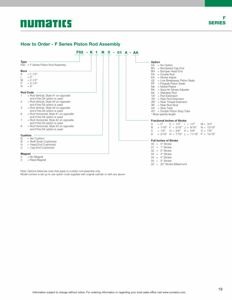
How to Order - F Series Piston Rod Assembly
TypeF92 = F Series Piston Rod Assembly
BoreK = 1-1/2"L = 2"M = 2-1/2"P = 3-1/4"R = 4"
Rod Code1 = Rod Vertical, Style #1 on opposite
end if the DA option is used2 = Rod Vertical, Style #2 on opposite
end if the DA option is used3 = Rod Vertical, Style #3 on opposite
end if the DA option is used6 = Rod Horizontal, Style #1 on opposite
end if the DA option is used7 = Rod Horizontal, Style #2 on opposite
end if the DA option is used8 = Rod Horizontal, Style #3 on opposite
end if the DA option is used
CushionN = No CushionB =H =C =
Both Ends CushionedHead End CushionedCap End Cushioned
Magnet0 = No Magnet2 = Reed Magnet
1 N 0 AAK
OptionAA =BC =BH =DA =KA =LB =PP = Polypak Piston SealsNA =RA =SA =1A* =1B* =2B* =3B =4A* =4D* =
No OptionBumpered Cap EndBumper Head EndDouble RodStroke AdjustLow Breakaway Piston Seals
Nickel PlatedSave Air Stroke AdjusterStainless RodRod ExtensionRear Rod ExtensionRear Thread ExtensionRear Rod StudStop TubeDouble Piston Stop Tube
* Must specify length
Fractional Inches of StrokeA 0" E 1/4" I 1/2" M 3/4"B 1/16" F 5/16" J 9/16" N 13/16"C 1/8" G 3/8" K 5/8" O 7/8"D
==== 3/16" H
==== 7/16" L
==== 11/16" P
==== 15/16"
Full Inches of Stroke00 = 0" Stroke01 = 1" Stroke02 = 2" Stroke03 = 3" Stroke04 = 4" Stroke05 = 5" Stroke20 = 20" Stroke (Maximum)
F92 - -- 01 A
Note: Options listed are ones that apply to a piston rod assembly only.Model number is set up to use option code supplied with original cylinder or with any above.

Information subject to change without notice. For ordering information or regarding your local sales office visit www.numatics.com.20
FSERIES
How to Order - F Series Repair Kit
TypeF98 = F Series Repair Kit
BoreK = 1-1/2"L = 2"M = 2-1/2"P = 3-1/4"R = 4"
CushionN = No CushionB = Both Ends CushionedH = Head End CushionedC = Cap End Cushioned
N AAK
OptionsAA = No OptionDA = Double RodLB = Low BreakawayMB = Rear Metallic Rod ScraperNA = Nickel PlatedPB = Rear Polypak Rod SealPP = PolyPak Piston SealRA = Save Air Stroke Adjuster4D = Double Piston Stop Tube
F98 - -
Note: Options listed are ones that apply to a repair kit only.Model number is set up to use option code supplied with original cylinder or with any above.
How to Order - F Series Seal Kit
TypeF97 = F Series Seal Kit
BoreK 1-1/2"L 2"M 2-1/2"P 3-1/4"R
===== 4"
CushionN No CushionB Both Ends CushionedH Head End CushionedC
==== Cap End Cushioned
A AAK
OptionsAA =DA =LB =MB =PB =
No OptionDouble RodLow BreakawayRear Metallic Rod ScraperRear Polypak Rod Seal
PP = PolyPak Piston SealRA =4D =
Save Air Stroke AdjusterDouble Piston Stop Tube
F97 - -
Note: Options listed are ones that apply to a seal kit only.Model number is set up to use option code supplied with original cylinder or with any above.

Information subject to change without notice. For ordering information or regarding your local sales office visit www.numatics.com.21
FSERIES
Piston Rod Assembly Kit Removal/Installation Instructions

Information subject to change without notice. For ordering information or regarding your local sales office visit www.numatics.com.22
FSERIES
Repair and Seal Kit Removal/Installation Instructions

Information subject to change without notice. For ordering information or regarding your local sales office visit www.numatics.com.23
FSERIES
1
1312
5
10
11
8 9
8 67
1 4
23 2
1617
1615
14
18
19
20
2126
24
23
22
25
DiagramsPneumatic Service Temperatures:Nitrile Seals: -10˚F (-23˚C) to 165˚F (74˚C)
Head, Cap, and Bushing Assembly
Piston/Rod Assembly
Cylinder Assembly and Tie Rod Torque
F Series
Part # Description
Parts included in:
Seal Kit
Repair Kit
Piston/Rod Assembly
1 Rod Seal/Wiper X
2 Bushing O-ring X
3 Head Cushion Seal X X
4 Bushing
5 Loaded Bushing Assembly X
6 Cap
7 Cap Cushion Needle
8 Tube End Seal X X
9 Cap Cushion Seal X X
10 Head
11 Head Cushion Needle
12 Bushing Retainer
13 Retainer Screws
14 Wearband X X
15 Magnet X
16 Back-up Rings X X
17 Piston Seal X X
18 Head Cushion Spear X
19 Cap Cushion Spear X
20 Piston X
21 Tube
22 Hex Bolts
23 Sleeve Bolts
24 Tooling Plate
25 Tooling Plate Screw
26 Rods X
Information subject to change without notice. For ordering information or regarding your local sales office visit www.numatics.com.24
FSERIES
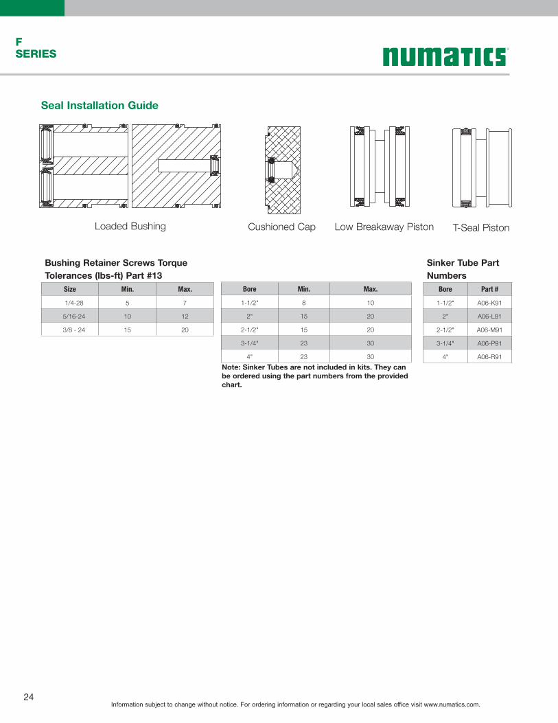
Seal Installation Guide
Loaded Bushing Cushioned Cap Low Breakaway Piston T-Seal Piston
Bushing Retainer Screws Torque Tolerances (lbs-ft) Part #13
Size Min. Max.
1/4-28 5 7
5/16-24 10 12
3/8 - 24 15 20
Bore Min. Max.
1-1/2" 8 10
2" 15 20
2-1/2" 15 20
3-1/4" 23 30
4" 23 30
Sinker Tube Part Numbers
Bore Part #
1-1/2" A06-K91
2" A06-L91
2-1/2" A06-M91
3-1/4" A06-P91
4" A06-R91Note: Sinker Tubes are not included in kits. They can be ordered using the part numbers from the provided chart.

Information subject to change without notice. For ordering information or regarding your local sales office visit www.numatics.com.25
FSERIES

World Class Supplier of Pneumatic Components
World Headquarters
Numatics, Inc. | Tel (248) 596-3200 | www.numatics.com | email: [email protected] Rev 02/15 10M-IPC-1/09© Numatics Inc. 2009 - 2012 Numatics® is registered in the United States and elsewhere
USA Numatics, Incorporated46280 Dylan DriveNovi, Michigan 48377
P: 248-596-3200 F: 248-596-3201
Canada Numatics, LtdP: 519-758-2700 F: 519-758-5540
Brazil Ascoval Ind.e Comercio LtdaP: (55) 11-4208-1700 F: (55) 11-4195-3970
México - Ascomatica SA de CVP: 52 55 58 09 56 40 (DF y Area metropolitana)P: 01 800 000 ASCO (2726) (Interior de la República) F: 52 55 58 09 56 60