nonfilling carbon coating of article porous silicon ...xx 000 000 xxxx b reported to substantially...
TRANSCRIPT
LU ET AL . VOL. XXX ’ NO. XX ’ 000–000 ’ XXXX
www.acsnano.org
A
CXXXX American Chemical Society
Nonfilling Carbon Coating ofPorous Silicon Micrometer-SizedParticles for High-PerformanceLithium Battery AnodesZhenda Lu,†,§ Nian Liu,†,§ Hyun-Wook Lee,† Jie Zhao,† Weiyang Li,† Yuzhang Li,† and Yi Cui*,†,‡
†Department of Materials Science and Engineering, Stanford University, Stanford, California 94305, United States and ‡Stanford Institute for Materials and EnergySciences, SLAC National Accelerator Laboratory, 2575 Sand Hill Road, Menlo Park, California 94025, United States. §Z. Lu and N. Liu contributed equally to this work.
Intense academic and industrial efforthas been devoted to developing re-chargeable lithium-ion batteries with
high energy density, long cycle life, andlow cost for various technological applica-tions, including portable electronics, electricvehicles, and grid-scale energy storagesystems.1�4 Surface coatings on electrodematerials are effective ways to improve thebattery performance by both enhancingthe electronic conductivity and minimizingthe electrode/electrolyte interfacial side re-action.5�8 Conformal coatings are highlydesired for this purpose, because uncoatedareas remain vulnerable to attack by theelectrolyte, compromising the functionalityof the protection layer. However, for materi-als with large volume change, it is challen-ging to realize a stable coating since a largevolume change ruptures the coating.
Silicon is regarded as one of the mostpromising anode materials for next-genera-tion lithium-ion batteries due to its 10 timeshigher specific capacity than the existinggraphite anodes.9�12 However, silicon ex-periences large volume changes (up to4 times) during the lithiation and delithiationprocesses. This volume change not onlyleads to rapid particle pulverization andisolation but also makes it difficult to coata stable protection layer to maintain thesolid�electrolyte interphase (SEI). The accu-mulated SEI eventually blocks the transportof Liþ and e�, causing the cell to fail.13�15
Significant progress has been achieved toaddress these issues by combining a con-formal coating with internal void space.16
For example, double-walled Si nanotubes,17
Si�C yolk shell nanostructures,18�21 andpomegranate-like Si structures22 have been
* Address correspondence [email protected].
Received for review September 23, 2014and accepted March 4, 2015.
Published online10.1021/nn505410q
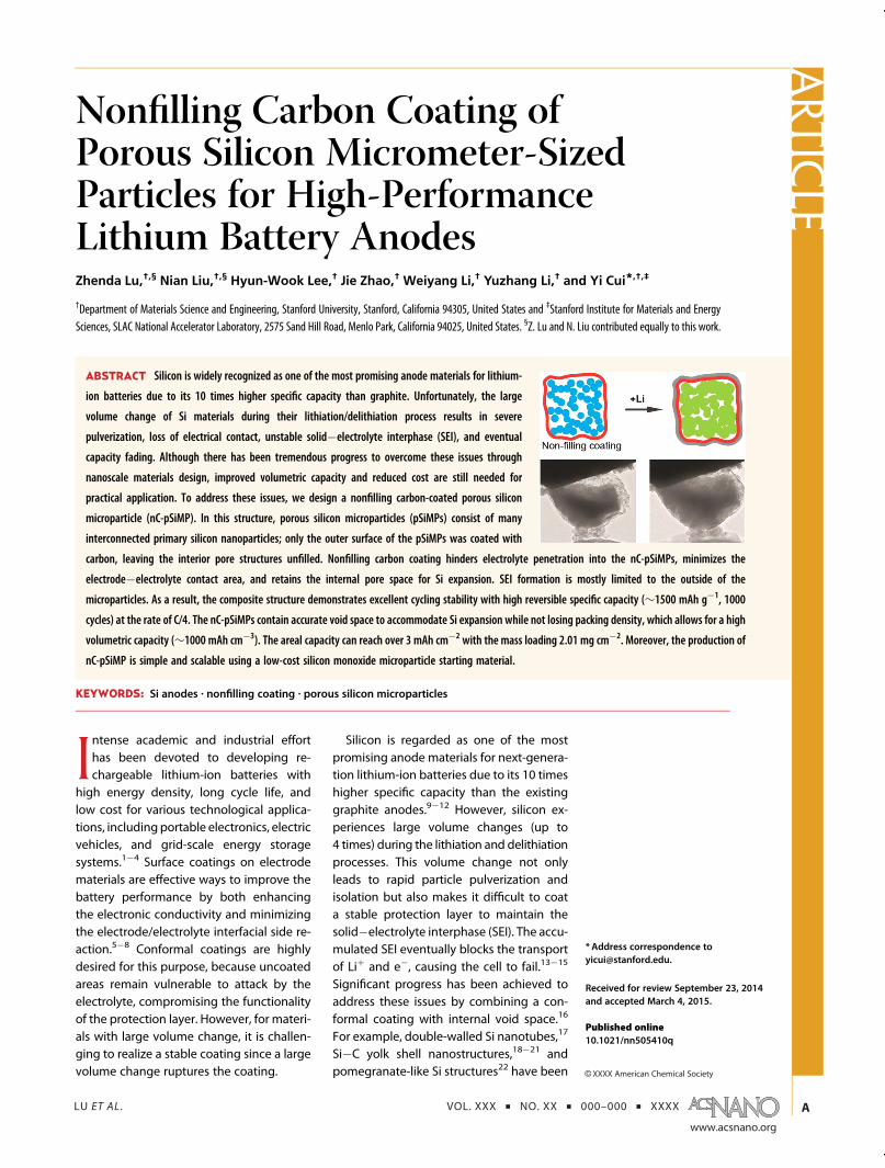
ABSTRACT Silicon is widely recognized as one of the most promising anode materials for lithium-
ion batteries due to its 10 times higher specific capacity than graphite. Unfortunately, the large
volume change of Si materials during their lithiation/delithiation process results in severe
pulverization, loss of electrical contact, unstable solid�electrolyte interphase (SEI), and eventual
capacity fading. Although there has been tremendous progress to overcome these issues through
nanoscale materials design, improved volumetric capacity and reduced cost are still needed for
practical application. To address these issues, we design a nonfilling carbon-coated porous silicon
microparticle (nC-pSiMP). In this structure, porous silicon microparticles (pSiMPs) consist of many
interconnected primary silicon nanoparticles; only the outer surface of the pSiMPs was coated with
carbon, leaving the interior pore structures unfilled. Nonfilling carbon coating hinders electrolyte penetration into the nC-pSiMPs, minimizes the
electrode�electrolyte contact area, and retains the internal pore space for Si expansion. SEI formation is mostly limited to the outside of the
microparticles. As a result, the composite structure demonstrates excellent cycling stability with high reversible specific capacity (∼1500 mAh g�1, 1000
cycles) at the rate of C/4. The nC-pSiMPs contain accurate void space to accommodate Si expansion while not losing packing density, which allows for a high
volumetric capacity (∼1000 mAh cm�3). The areal capacity can reach over 3 mAh cm�2 with the mass loading 2.01 mg cm�2. Moreover, the production of
nC-pSiMP is simple and scalable using a low-cost silicon monoxide microparticle starting material.
KEYWORDS: Si anodes . nonfilling coating . porous silicon microparticles
ARTIC
LE

LU ET AL . VOL. XXX ’ NO. XX ’ 000–000 ’ XXXX
www.acsnano.org
B
reported to substantially improve the cycling life ofSi-based anodes. However, these core�shell structureswith void space were all based on Si nanostructures,which introduce new challenges to the practical appli-cation of Si batteries.23�29 First, the nanostructuredmaterials are sparsely packed, making it difficult toachieve robust electronic and ionic connections be-tween neighboring nanoparticles. Thus, high massloading of active materials and high volumetric capa-city remain challenging. There are only a few examplesto address these issueswith promise.20,22 Second,mostnanostructures require expensive and multistep syn-thesis. For example, silicon nanoparticles are producedby pyrolysis of silane gas, while the well-designed voidspace is introduced using a sacrificial template. Theexisting Si nanostructures are still too expensive forlarge-scale use.To address these concerns, here we design a non-
filling carbon-coated porous Si microparticle (nC-pSiMP) core�shell structure as anode material. Thecore is a porous Si microparticle composed of inter-connected Si primary nanoparticles,30,31 and the shellis a confining carbon layer that allows Liþ to passthrough. No carbon exists in the pore space of Si, whichis different from all the previous demonstrations inthe literature, where the carbon coating penetratesinto the structures.32�37 Such a design offers multipleattractive features for large-volume-change anodematerials: (1) a commercially available SiO microparti-cle source and a simple synthesis procedure make theprocess highly cost-effective and scalable. (2) Theinterconnected Si primary nanoparticles formed bythermal disproportionation of SiO microparticles en-sures the size of the primary Si building blocks is lessthan 10 nm (Figure 2d, Supporting Information),36,38�40
which is below the critical fracture size.41,42 Thermaldisproportionation also results in densely packed pri-mary Si nanoparticles, which allow for good electronicconductivity among neighboring particles. (3) Carboncoats the exterior surface of the Si microparticles,prevents electrolyte diffusion into the interior porespace, and restricts SEI formation to the outer surface.(4) The nonfilling coating retains enough internal voidspace to accommodate the volume expansion of Sinanoparticles and keeps the carbon shell intact duringthe electrochemical cycling (Figure 1). (5) The non-filling coating introduces less carbon to the compos-ites, which not only increases specific capacity but alsoincreases the initial Coulombic efficiency due to Litrapping in amorphous carbon.
RESULTS
Material Synthesis and Characterization. Commerciallyavailable SiO microparticles were first conformallycoated with a layer of resorcinol-formaldehyde resin(RF) in diluted ammonia aqueous solution.43 Then thecoated structures were heated to 950 �C for 5 h underAr. During the heating process, phase separation inSiO occurs to form interconnected Si nanoparticlesembedded in a SiO2 matrix due to the thermal dis-proportionation of SiO.36,39 Simultaneously, the RFcoating was converted to a carbon coating at hightemperature to wrap the as-formed Si/SiO2 compos-ites. After removing the SiO2 matrix with HF solution,enough void space was generated to allow Si freeexpansion without breaking the outer carbon layer.This synthesis approach has three advantages. First,the chemical sources used in the synthesis (SiO micro-particle, resorcinol, formaldehyde, ammonia, and HF)are all used industrially with low cost, providing greatpromise for mass production. Second, the carbonconversion and SiO thermal disproportionation areachieved in one heating step, saving energy duringthe preparation process. Third and most importantly,void space is formed by SiO disproportionation and HFetching without any intentionally added templates.The void space volume is sufficient for Si expansion, asevidenced by the in situ TEM results shown in Figure 4.
For a clear comparison of structuremorphology, weprepared porous silicon microparticles with differentcarbon coatings: no coating, impregnating coating,and nonfilling coating, simplified as pSiMP, iC-SiMP,and nC-SiMP, respectively (Figure 2a�c). Representa-tive TEM and SEM images are shown in Figure 2d�i.Without a carbon coating, one can easily observe theporous nature of the microparticles in TEM (Figure 2d)and the enlarged SEM images in the inset (Figure 2g).The interconnected Si nanoparticles are very uniform,with most less than 10 nm. For iC-SiMPs, the porousnature of the microparticles is not obvious in Figure 2eand h because of the carbon penetration into theinterior pore space. For the nonfilling coated structure,
Figure 1. Schematic of coating design on mesoporous Simicroparticles (pSiMPs) and their structural evolution dur-ing cycling. For impregnation coating, a carbon layer iscoated on each of the Si nanoparticle domains. Upon firstcycling, the tremendous volume expansion of Si domainsbreaks the coating, exposing the silicon surface to theelectrolyte, and resulting in excessive SEI formation. For anonfilling coating, however, carbon only coats the outsideof the microparticle, leaving the internal void space for Siexpansion. Upon (de)lithiation, the outer carbon layer re-mains intact. As a result, the SEI outside the microstructureis not ruptured during cycling and remains thin.
ARTIC
LE

LU ET AL . VOL. XXX ’ NO. XX ’ 000–000 ’ XXXX
www.acsnano.org
C
the feature of interconnected Si nanoparticles is clearlyexhibited again because the carbon layer only wrapsthe outer layer of the microparticle, as shown inFigure 2f. The SEM images (Figure 2g�i) show thatthe morphology of the microparticles is stable duringthe polymer coating, thermal disproportion, and HFetching processes. Auger electron spectroscopy (AES)elemental mapping of the interior of nC-pSiMPs wasutilized to further confirm the carbon distribution inthe composite structures (Figure 2j�l). After the outercarbon surface was removed by Ar ion beam sputter-ing (5 kV, 5 mA) for 4 min, only weak carbon signalswere observed. This suggests that little carbon pene-trates into the interior Si porous structures.
X-ray diffraction (XRD) measurement (Figure 3a)indicates that the nC-pSiMP has a pure silicon phase(JCPDS card No. 27-1402). Calculationwith the Debye�Scherrer formula using the strongest peak (2θ = 28.5�)gives a grain size of less than 5 nm for the samples. Thisis consistent with TEM images showing that the micro-particles are composed of silicon nanoparticle do-mains. Raman spectroscopy (Figure 3b) shows three
peaks at 499, 1340, and 1583 cm�1, corresponding tothe silicon and carbon D and G bands, respectively.X-ray photoelectron spectroscopy (XPS, Figure 3c) alsodemonstrates the coexistence of silicon and carbon.Compared with the carbon, the negligible signal of Si2pin XPS analysis shows a very low surface atomicpercentage of Si, clearly indicating that the carboncoating is conformal to completely seal the pSiMPs.The mass percentage of silicon in the nC-pSiMP struc-ture is found to be 89% by thermogravimetric analysis(TGA, Figure 3d), while the percentage decreases to79% in impregnating coated structure.
A sufficient internal void space is necessary to keepthe core�shell structure intact and maintain the struc-tural integrity of the silicon anode. To evaluatewhetherthe void space is enough for the Si expansion or not, weperformed an in situ TEM study for the nC-pSiMPs withdifferent sizes. The in situ electrochemical cell is basedon our previous studies and is shown schematicallyin Figure 4a. Figure 4b demonstrations a series ofimages taken form a movie of the in situ lithiationof the composite with a size of around 500 nm
Figure 2. Morphology characterization of pSiMPs with different coatings. Schematic and TEM and SEM images of pSiMPswithout coating (a, d, and g), impregnating C-coating (b, e, and h), and nonfilling C-coating (c, f, and i). Insets are magnifiedSEM images showing the surface of themicroparticles. (j�l) Auger electron spectron (AES) elemental mapping of nC-pSiMPs:(j) original sample; (k) after the top surface was removed by Ar ion beam sputtering (5 kV, 5 mA) for 4 min; (l) AES elementalmapping after removing the surface. The majority of C signals are outside the microparticles, showing that very little carbonpenetrated into the pore space of the Si microstructures.
ARTIC
LE

LU ET AL . VOL. XXX ’ NO. XX ’ 000–000 ’ XXXX
www.acsnano.org
D
(Supplementary Movie 1). In the first image (0 s, beforelithiation), the porous Si particle is visible within asurrounding C shell. Then, the particle expands involume as Li diffuses through the carbon layer andalloys with Si. The particle is partially lithiated after 30 s.After 1min, the contrast inside the carbon shell changeslittle from TEM images, indicating full lithiation is
reached. All the void space is occupied by lithiatedsilicon material, and no fracture of the carbon shell isobserved after full lithiation. For the particle size above1 μm (Figure 4c, Supplementary Movie 2), more time isneeded for the full lithiation (150 s). The porousmicrosized particle also provides enough void spaceto accommodate the Si full expansionwithout rupturing
Figure 4. Volume expansion of nC-pSiMPs during lithiation characterized by in situ TEM. (a) Schematic of the in situ TEMdevice. (b) Time-lapse images of the lithiation of a 500 nmparticle (also see SupplementaryMovie S1). Li transports along andacross the carbon layer to react with the Si inside, causing volume expansion. Because the pore structure provides enoughspace to accommodate this expansion, the carbon shell remains intact after full lithiation. (c) Lithiation of a 1 μm nC-pSiMP(also see Supplementary Movie S2).
Figure 3. Characterization of nC-pSiMPs. (a) XRD pattern; all the peaks are attributed to crystalline Si. (b) Raman spectrum.(c) XPS spectrum. Inset is a high-resolution XPS spectrum of the Si2p peaks. The signal of Si is significantly low comparedwiththat of carbon, indicating pSiMPs were completely covered by carbon. (d) TGA profiles. The red dashed curve demonstratesthe TGA profile of iC-pSiMPs for comparison.
ARTIC
LE

LU ET AL . VOL. XXX ’ NO. XX ’ 000–000 ’ XXXX
www.acsnano.org
E
the outer carbon shell. All these results suggest thatwithout any complex design or sacrificial template ourprocedure can directly generate a well-defined voidspace together with a nonfilling coating. This voidspace is mostly occupied when Si expands in thelithiated state, which maximizes the volumetric capac-ity. Meanwhile the carbon shell remains intact evenafter complete Si lithiation, effectively preventing thebattery anode from changing structurally upon cyclingand thus increasing the cycling life of the battery.
Electrochemical Performance. The electrochemical cy-cling performance of the composite electrodes wasevaluated using deep charge/discharge galvanostatic
cycling from 1 to 0.01 V (Figure 3a�c). As shown inFigure 5a, the initial reversible capacity of nC-SiMPsreaches 1798mAh g�1 for a rate of C/20 (1C = 4.2 A g�1
active materials). If not mentioned, all the reportedcapacities are based on the total mass of Si/C compos-ites. Because the mass percentage of silicon is 89% inthe composite, the capacity with respect to silicon isabout 2020 mAh g�1. The volumetric capacity for thisanode is determined to be 1003 mAh cm�3 (based onan areal mass loading of 0.614 mg cm�2, a laminatethickness of 11 μm, and an electrode density of0.55 g cm�3), which is much larger than the600mAh cm�3 obtained from state-of-the-art graphite
Figure 5. Electrochemical characterization of nC-pSiMPanodes. All the specific capacities of the anodes are basedon the totalmass of the active materials (Si and C in the nC-pSiMPs). (a) Reversible delithiation capacity for the first 1000 galvanostaticcycles of the pSiMPs with different coating. The active material mass loading was around 0.5 mg cm�2. The rate was C/20 forthe first three cycles and then C/4 for later cycles. 1C = 4.2 A g�1. (b) Voltage profiles of nC-pSiMPs plotted for the first, fourth,250th, 500th, 750th, and 1000th cycles. (c) High areal mass loading test (up to 2.0mg cm�2 activematerials) of nC-pSiMPs. Allelectrodeswere cycled at 0.05mA cm�2 for the initial three cycles and 0.25mA cm�2 for later cycles. (d) Typical SEM images ofnC-pSiMPs after 100 cycles. Themorphologies of SiMPswere largely unchanged compared to those of the original Si samples.(e) Thickness of an nC-pSiMP electrode before cycling and after lithiation to 0.05 V at the 100th cycle.
ARTIC
LE

LU ET AL . VOL. XXX ’ NO. XX ’ 000–000 ’ XXXX
www.acsnano.org
F
anodes.12 From the fourth to 1000th cycle at a rate ofC/4, the capacity remains in the range from 1463 to1560 mAh g�1, and no obvious decay is found. After1000 cycles, over 1490 mAh g�1 capacity remained,which is about 4 times the theoretical capacity ofgraphite. Under the same conditions, iC-pSiMPs(without an internal void space) demonstrated notice-able decay after 200 cycles. Bare pSiMPs decay evenmore significantly, with a capacity retention lessthan 45% after 1000 cycles. The voltage profiles ofnC-pSiMPs show the typical electrochemical featuresof silicon (Figure 5b). The shape of the profiles does notchange from the 250th to the 1000th cycle, indicatingstable electrochemical behavior of the nonfillingcoated structures.
It should be noted that many publications reportonly specific capacity normalized by the weight of theactive materials, and low areal mass loading helps toachieve the stable cycling.17,44 However, high arealmass loading is necessary for practical batteries. Wetested the silicon electrodes with different areal massloading of composites up to 2.01 mg cm�2 (Figure 5c).A reversible areal capacity of 3.22 mAh cm�2 isachieved at the first cycle with a current density of0.05 mA cm�2, corresponding to a specific capacity of1602 mAh g�1 based on the total mass of the Si/Ccomposites. The capacity remains stable during thesubsequent fourth to 100th cycles at a higher rate of0.25 mA cm�2, and the areal capacity is maintained at2.84 mAh cm�2 after 100 cycles, which is close to thecapacity of a commercial lithium-ion battery cell. Theelectrodes with slightly low areal mass loadings of1.42 and 1.13 mg cm�2 offer stable areal capacities of2.09 and 1.53 mAh cm�2, respectively. Little decreaseof specific capacity is found when areal mass loading isincreased (1505, 1531, 1359, 1474, and 1413 mAh g�1
for the corresponding areal mass loading of 0.37, 0.61,1.13, 1.42, and 2.01mg cm�2), confirming the excellentperformance of the Si anode originates from the well-designed structures.
DISCUSSION
We attribute the exceptional electrochemical stabil-ity to the novel nanoscale architecture of the Si�Ccomposite electrode. The void space generated duringthe thermal disproportionation and etching processretains secondary particles and stabilizes the SEI on thesurface. After 100 deep cycles, the morphology of thenC-pSiMPs with and without SEI was examined underSEM (Figure 5d). The micrometer-sized secondary par-ticle is covered by a thin and uniform SEI layer. Anintact carbon shell with silicon inside is clearly shownafter removing the SEI with diluted acid. The wholeparticle is still completely wrapped by carbon. Thisfurther suggests the importance of the nonfillingcarbon coating on the structural integrity of pSiMPsduring the electrochemical cycling. The thickness of
the electrode slightly increases from 16.2 μm to17.3 μm after 100 deep cycles (Figure 5e). This smallvolume change (only 8%) guarantees the excellentbattery performance in high mass loading cells.Moreover, the void space is automatically formed
through thermal disproportionation of SiO followed byetching away SiO2. According to the chemical equation
2SiO f Siþ SiO2 (1)
2 mol of SiO will generate 1 mol of Si and 1mol of SiO2.On the basis of the density of SiO, Si, and SiO2 (2.1, 2.3,and 2.6 g cm�3), we estimate that 1.00 cm3 of SiO cangenerate 0.30 cm3 of Si and 0.55 cm3 of SiO2 afterthermal disproportionation. Therefore, the SiO micro-particle will have a volume decrease of 15% after heattreatment, which creates a gap between the siliconparticle and carbon shell, as evidenced by the TEMimage (Figure 2f). Moreover, the volume ratio of Si tovoid space is about 3:7 after removing SiO2. Thisvolume ratio allows for free volume expansion of Simaterials without breaking the C shell. There is nearlyno excess void space when the Si�C composite is fullylithiated, providing a high volumetric energy density.No complex designs or sacrificial templates are neededfor this well-defined void space, making the prepara-tion procedure very simple and cost-effective.The nonfilling C coating not only maintains structur-
al integrity of the secondary particles but also de-creases the carbon fraction in composites from 21%to 11% compared with that in the impregnating coat-ing (TGA analysis, Figure 3d). Low carbon contentincreases the specific capacity of the composite struc-tures. In addition, low carbon content increases the firstcycle Coulombic efficiency (CE) because amorphouscarbon irreversibly reacts with lithium at low potential.As a result, the first cycle reversible capacity of thenonfilling coated structure reaches 1798 mAh g�1
with respect to the total mass of the Si/C composite,while the CE reaches 78%. As a comparison, theimpregnating coated structure has a reversiblecapacity of 1716 mAh g�1 with 68% initial CE.
CONCLUSION
In summary, we have designed a nonfilling carbon-coated SiMP structure to address the issues of materialfracture and SEI stability in a Si anode. The thermaldisproportionation and etching processes provide theinterconnected Si nanoparticles sufficient void spacefor Si expansion, while the nonfilling coated carbonshell maintains the structural integrity of the SiMPs andprevents continuous SEI formation. As a result, theanodes can be deeply cycled up to 1000 times withcapacity remaining around 1500 mAh g�1. The arealcapacity can reach higher than 3 mAh cm�2 withoutobvious capacity decay after 100 cycles. In addition,the material synthesis and electrode fabrication pro-cesses are simple, scalable, highly reproducible, and
ARTIC
LE
LU ET AL . VOL. XXX ’ NO. XX ’ 000–000 ’ XXXX
www.acsnano.org
G
compatible with slurry coatingmanufacturing technol-ogy. As a result, the nC-pSiMPs presented here show
great promise for future mass production as a high-performance composite anode.
METHODS
Synthesis of nC-pSiMPs. The schematic of the preparationprocedure is shown in Supporting Information. Commercialsiliconmonoxide microparticles (SiOMPs, 325mesh) were firstcoated with a resorcinol-formaldehyde resin layer. The RF wasthen converted into a carbon layer under argon at 950 �C for5 h. During this annealing process, SiO MPs phase separate toform a Si/SiO2 composite with interconnected Si nanoparticlesembedded in a SiO2 matrix due to the disproportionation ofSiO. Finally, the SiO2 matrix was removed with 10 wt % HFsolution to form the final product, nC-pSiMPs. For the bareporous structure without C coating, SiO was directly heated to950 �C under the same conditions and then SiO2 was removedwith HF. Impregnating coated samples could be achievedby coating RF on these bare pSiMPs followed by a carboniza-tion process.
Characterization. The weight percentage of Si and C in theC-coated pSiMPs was determined from the weight loss curvesmeasured under simulated air atmosphere (20% O2 þ 80% Ar,both are ultrapurity grade gases from Airgas) on a TG/DTAInstruments Netzsch STA 449 with a heating rate of 5 �C/min.SEM and TEM images were taken using a FEI XL30 Sirion SEM(accelerating voltage 5 kV) and a FEI Tecnai G2 F20 X-TWIN(accelerating voltage 200 kV), respectively. Other characteri-zation was carried out by X-ray photoelectron spectroscopy(PHI Versa Probe 5000, Physical Electronics, USA), X-ray diffrac-tion (PANalytical X'Pert, Ni-filtered Cu KR radiation), and Ramanspectroscopy (531 nm excitation laser, WITEC Raman spec-trometer).
In Situ TEM. A specialized dual-probe electrical biasing holder(Nanofactory 105 Instruments) was used. By biasing theworkingelectrode between�2.5 and�3 V versus the counter electrode,Liþ ions flow through the lithium oxide/nitride layer and arereduced at the working electrode, where they react with carbonand alloy with the silicon in the coated structures (Figure 4a).The lithiation time of the C-coated porous structures is less than3 min (Figure 4b,c).
Electrochemical Mearsurement. To prepare the working elec-trodes, the various pSiMPsweremixedwith carbonblack (Super P)and polyvinylidene fluoride binder (80:10:10 by weight) inN-methyl-2-pyrrolidinone to form a slurry. This slurry was thencoated onto copper foil using a doctor blade and dried undervacuum to form the working electrode. Coin cells (2032-type)were assembled in an argon-filled glovebox using lithium foil asthe counter electrode. The electrolyte was 1.0M LiPF6 in 1:1 w/wethylene carbonate/diethyl carbonate, with 1 vol % vinylenecarbonate added to improve the cycling stability. All the cellswere cycled between 0.01 and 1 V versus Li/Liþ. Specific capacityvalues were calculated based on the total mass of the Si/Ccomposite structures.
Conflict of Interest: The authors declare no competingfinancial interest.
Supporting Information Available: More detailed synthesisprocedures, additional SEM images, Coulombic efficiency, andin situ TEMmovies are available free of charge via the Internet athttp://pubs.acs.org.
Acknowledgment. Y.C. acknowledges support from theAssistant Secretary for Energy Efficiency and RenewableEnergy, Office of Vehicle Technologies, of the U.S. Departmentof Energy under the Battery Materials Research (BMR) Program.H.W.L. acknowledges the Basic Science Research Programthrough the National Research Foundation of Korea (NRF)funded by the Ministry of Education, Science and Technology(contract no. 2012038593).
REFERENCES AND NOTES1. Arico, A. S.; Bruce, P.; Scrosati, B.; Tarascon, J.-M.; van
Schalkwijk, W. Nanostructured Materials for AdvancedEnergy Conversion and Storage Devices. Nat. Mater.2005, 4, 366–377.
2. Armand, M.; Tarascon, J. M. Building Better Batteries.Nature 2008, 451, 652–657.
3. Bruce, P. G.; Freunberger, S. A.; Hardwick, L. J.; Tarascon,J.-M. Li-O2 and Li-S Batteries with High Energy Storage.Nat. Mater. 2012, 11, 19–29.
4. Dunn, B.; Kamath, H.; Tarascon, J.-M. Electrical EnergyStorage for the Grid: A Battery of Choices. Science 2011,334, 928–935.
5. Chen, Z.; Qin, Y.; Amine, K.; Sun, Y. K. Role of SurfaceCoating on Cathode Materials for Lithium-Ion Batteries.J. Mater. Chem. 2010, 20, 7606–7612.
6. Sun, Y.-K.; Myung, S.-T.; Park, B.-C.; Prakash, J.; Belharouak,I.; Amine, K. High-Energy Cathode Material for Long-Lifeand Safe Lithium Batteries. Nat. Mater. 2009, 8, 320–324.
7. Wang, J.; Yang, J.; Tang, Y.; Liu, J.; Zhang, Y.; Liang, G.;Gauthier, M.; Karen Chen-Wiegart, Y.-c.; Norouzi Banis, M.;Li, X., et al. Size-Dependent Surface Phase Change ofLithium Iron Phosphate during Carbon Coating. Nat.Commun. 2014, 5, 4415.
8. Wei Seh, Z.; Li, W.; Cha, J. J.; Zheng, G.; Yang, Y.; McDowell,M. T.; Hsu, P.-C.; Cui, Y. Sulphur�TiO2 Yolk�Shell Nano-architecture with Internal Void Space for Long-CycleLithium�Sulphur Batteries. Nat. Commun. 2013, 4, 1331.
9. Beaulieu, L. Y.; Eberman, K. W.; Turner, R. L.; Krause, L. J.;Dahn, J. R. Colossal Reversible Volume Changes in LithiumAlloys. Electrochem. Solid-State Lett. 2001, 4, A137–A140.
10. Deshpande, R.; Cheng, Y.-T.; Verbrugge, M. W. ModelingDiffusion-Induced Stress in Nanowire Electrode Struc-tures. J. Power Sources 2010, 195, 5081–5088.
11. Obrovac, M. N.; Christensen, L. Structural Changes inSilicon Anodes during Lithium Insertion/Extraction. Elec-trochem. Solid-State Lett. 2004, 7, A93–A96.
12. Obrovac, M. N.; Christensen, L.; Le, D. B.; Dahn, J. R. AlloyDesign for Lithium-Ion Battery Anodes. J. Electrochem. Soc.2007, 154, A849–A855.
13. Aurbach, D. Review of Selected Electrode�Solution Inter-actions Which Determine the Performance of Li and Li IonBatteries. J. Power Sources 2000, 89, 206–218.
14. Chan, C. K.; Ruffo, R.; Hong, S. S.; Cui, Y. Surface Chemistryand Morphology of the Solid Electrolyte Interphase onSilicon Nanowire Lithium-Ion Battery Anodes. J. PowerSources 2009, 189, 1132–1140.
15. Verma, P.; Maire, P.; Novák, P. A Review of the Features andAnalyses of the Solid Electrolyte Interphase in Li-IonBatteries. Electrochim. Acta 2010, 55, 6332–6341.
16. Obrovac, M. N.; Chevrier, V. L. Alloy Negative Electrodes forLi-Ion Batteries. Chem. Rev. 2014, 114, 11444–11502.
17. Wu, H.; Chan, G.; Choi, J. W.; Ryu, I.; Yao, Y.; McDowell, M. T.;Lee, S. W.; Jackson, A.; Yang, Y.; Hu, L.; et al. Stable Cyclingof Double-Walled Silicon Nanotube Battery Anodesthrough Solid-Electrolyte Interphase Control. Nat. Nano-technol. 2012, 7, 310–315.
18. Liu, N.; Wu, H.; McDowell, M. T.; Yao, Y.; Wang, C.; Cui, Y. AYolk-Shell Design for Stabilized and Scalable Li-Ion BatteryAlloy Anodes. Nano Lett. 2012, 12, 3315–3321.
19. Wu, H.; Zheng, G.; Liu, N.; Carney, T. J.; Yang, Y.; Cui, Y.Engineering Empty Space between Si Nanoparticles forLithium-Ion Battery Anodes. Nano Lett. 2012, 12, 904–909.
20. Li, X.; Gu, M.; Hu, S.; Kennard, R.; Yan, P.; Chen, X.; Wang, C.;Sailor, M. J.; Zhang, J.-G.; Liu, J. Mesoporous Silicon Spongeas an Anti-Pulverization Structure for High-PerformanceLithium-Ion Battery Anodes. Nat. Commun. 2014, 5,5105.
ARTIC
LE

LU ET AL . VOL. XXX ’ NO. XX ’ 000–000 ’ XXXX
www.acsnano.org
H
21. Wang, B.; Li, X.; Zhang, X.; Luo, B.; Zhang, Y.; Zhi, L. Contact-Engineered and Void-Involved Silicon/Carbon Nano-hybrids as Lithium-Ion-Battery Anodes. Adv. Mater. 2013,25, 3560–3565.
22. Liu, N.; Lu, Z.; Zhao, J.; McDowell, M. T.; Lee, H.-W.; Zhao, W.;Cui, Y. A Pomegranate-Inspired Nanoscale Design forLarge-Volume-Change Lithium Battery Anodes. Nat.Nanotechnol. 2014, 9, 187–192.
23. Chan, C. K.; Peng, H.; Liu, G.; McIlwrath, K.; Zhang, X. F.;Huggins, R. A.; Cui, Y. High-Performance Lithium BatteryAnodes Using Silicon Nanowires. Nat. Nanotechnol. 2008,3, 31–35.
24. Liu, G.; Xun, S.; Vukmirovic, N.; Song, X.; Olalde-Velasco, P.;Zheng, H.; Battaglia, V. S.; Wang, L.; Yang, W. Polymers withTailored Electronic Structure for High Capacity LithiumBattery Electrodes. Adv. Mater. 2011, 23, 4679–4683.
25. Magasinski, A.; Dixon, P.; Hertzberg, B.; Kvit, A.; Ayala, J.;Yushin, G. High-Performance Lithium-Ion Anodes Using aHierarchical Bottom-up Approach. Nat. Mater. 2010, 9,353–358.
26. Park, M.-H.; Kim, M. G.; Joo, J.; Kim, K.; Kim, J.; Ahn, S.; Cui, Y.;Cho, J. Silicon Nanotube Battery Anodes. Nano Lett. 2009,9, 3844–3847.
27. Wu, H.; Cui, Y. Designing Nanostructured Si Anodes forHigh Energy Lithium Ion Batteries. Nano Today 2012, 7,414–429.
28. Evanoff, K.; Magasinski, A.; Yang, J.; Yushin, G. Nanosilicon-Coated Graphene Granules as Anodes for Li-Ion Batteries.Adv. Energy Mater. 2011, 1, 495–498.
29. Xu, Y.; Liu, Q.; Zhu, Y.; Liu, Y.; Langrock, A.; Zachariah, M. R.;Wang, C. Uniform Nano-Sn/C Composite Anodes forLithium Ion Batteries. Nano Lett. 2013, 13, 470–474.
30. Bang, B. M.; Lee, J.-I.; Kim, H.; Cho, J.; Park, S. High-Performance Macroporous Bulk Silicon Anodes Synthe-sized by Template-Free Chemical Etching. Adv. EnergyMater. 2012, 2, 878–883.
31. Thakur, M.; Sinsabaugh, S. L.; Isaacson, M. J.; Wong, M. S.;Biswal, S. L. Inexpensive Method for Producing Macro-porous Silicon Particulates (MPSPs) with Pyrolyzed Poly-acrylonitrile for Lithium Ion Batteries. Sci. Rep. 2012, 2, 795.
32. Ge, M.; Rong, J.; Fang, X.; Zhou, C. Porous Doped SiliconNanowires for Lithium Ion Battery Anode with Long CycleLife. Nano Lett. 2012, 12, 2318–2323.
33. Jung, D. S.; Hwang, T. H.; Park, S. B.; Choi, J. W. Spray DryingMethod for Large-Scale and High-Performance SiliconNegative Electrodes in Li-Ion Batteries. Nano Lett. 2013,13, 2092–2097.
34. Kim, H.; Cho, J. Superior Lithium Electroactive MesoporousSi@Carbon Core�Shell Nanowires for Lithium BatteryAnode Material. Nano Lett. 2008, 8, 3688–3691.
35. Kim, H.; Han, B.; Choo, J.; Cho, J. Three-Dimensional PorousSilicon Particles for Use in High-Performance LithiumSecondary Batteries. Angew. Chem., Int. Ed. 2008, 47,10151–10154.
36. Yi, R.; Dai, F.; Gordin, M. L.; Chen, S.; Wang, D. Micro-SizedSi-C Composite with Interconnected Nanoscale BuildingBlocks as High-Performance Anodes for Practical Applica-tion in Lithium-Ion Batteries. Adv. Energy Mater. 2013, 3,295–300.
37. Song, J.; Chen, S.; Zhou, M.; Xu, T.; Lv, D.; Gordin, M. L.; Long,T.; Melnyk, M.; Wang, D. Micro-Sized Silicon-Carbon Com-posites Composed of Carbon-Coated Sub-10 nm Si PrimaryParticles as High-Performance AnodeMaterials for Lithium-Ion Batteries. J. Mater. Chem. A 2014, 2, 1257–1262.
38. Lee, J.-I.; Choi, N.-S.; Park, S. Highly Stable Si-Based Multi-component Anodes for Practical Use in Lithium-Ion Bat-teries. Energy Environ. Sci. 2012, 5, 7878–7882.
39. Lee, J.-I.; Lee, K. T.; Cho, J.; Kim, J.; Choi, N.-S.; Park, S.Chemical-Assisted Thermal Disproportionation of PorousSilicon Monoxide into Silicon-Based Multicomponent Sys-tems. Angew. Chem., Int. Ed. 2012, 51, 2767–2771.
40. Yi, R.; Dai, F.; Gordin, M. L.; Sohn, H.; Wang, D. Influence ofSiliconNanoscale Building Blocks Size and Carbon Coatingon the Performance of Micro-Sized Si�C Composite Li-IonAnodes. Adv. Energy Mater. 2013, 3, 1507–1515.
41. Liu, X. H.; Zhong, L.; Huang, S.; Mao, S. X.; Zhu, T.; Huang,J. Y. Size-Dependent Fracture of Silicon Nanoparticlesduring Lithiation. ACS Nano 2012, 6, 1522–1531.
42. McDowell, M. T.; Ryu, I.; Lee, S. W.; Wang, C.; Nix, W. D.; Cui,Y. Studying the Kinetics of Crystalline Silicon NanoparticleLithiation with in Situ Transmission Electron Microscopy.Adv. Mater. 2012, 24, 6034–6041.
43. Li, N.; Zhang, Q.; Liu, J.; Joo, J.; Lee, A.; Gan, Y.; Yin, Y. Sol-GelCoating of Inorganic Nanostructures with Resorcinol-Formaldehyde Resin. Chem. Commun. 2013, 49, 5135–5137.
44. Gogotsi, Y.; Simon, P. True Performance Metrics in Electro-chemical Energy Storage. Science 2011, 334, 917–918.
ARTIC
LE