nonlinear observer-based control for pmsg wind...
TRANSCRIPT

lable at ScienceDirect
Energy 113 (2016) 248e257
Contents lists avai
Energy
journal homepage: www.elsevier .com/locate/energy
Nonlinear observer-based control for PMSG wind turbine
Roberto Fantino, Jorge Solsona*, Claudio BusadaInstituto de Investigaciones en Ingeniería El�ectrica (IIIE) “Alfredo Desages” (UNS-CONICET), Departamento de Ingeniería El�ectrica y de Computadoras,Universidad Nacional del Sur (UNS), 8000, Bahía Blanca, Argentina
a r t i c l e i n f o
Article history:Received 11 December 2015Received in revised form30 June 2016Accepted 7 July 2016Available online 19 July 2016
Keywords:Permanent magnet synchronous generatorWECSSensorless controlNonlinear observerMPPT
* Corresponding author. DIEC e UNS, Av. AlemArgentina.
E-mail address: [email protected] (J. Solsona).
http://dx.doi.org/10.1016/j.energy.2016.07.0390360-5442/© 2016 Elsevier Ltd. All rights reserved.
a b s t r a c t
This paper introduces a mechanical sensorless control strategy to be used in variable speed wind energyconversion systems based on permanent magnet synchronous generators. The goal of the controlstrategy is to track the wind turbine maximum power point. With the proposed strategy, mechanicalsensors are not needed to implement the control law. For this reason, electrical sensors -voltage andcurrent sensors-are only needed to build the control law.
In order to obtain estimates of the mechanical variables, a nonlinear Luenberger-like observer isdesigned. This observer only uses measurements of the electrical variables. The estimates are fed back tothe controller in order to build the mechanical sensorless control strategy.
The performance of the whole system is tested through simulations.© 2016 Elsevier Ltd. All rights reserved.
1. Introduction
Wind energy conversion systems (WECS) used in distributedgeneration must be able to inject energy in an efficient way. To thisend, nowadays, the use of speed variable permanent magnet syn-chronous generator (PMSG) has increased a lot. It is mainly becausePMSGs based WECSs have high efficiency and they reduce opera-tion and maintenance cost, since this scheme does not employneither gearbox nor slip rings. In addition, PMSGs basedWECSs canbe controlled for wind turbine maximum power point transfer(MPPT) operation, in a wide range of the wind speeds [1,2].
In order to transfer power from the generator to the grid, most ofWECSs include Voltage Source Converters (VSCs). However, overthe last few years, the use of topologies including Current SourceConverters (CSCs) have increased a lot. This is because these to-pologies present several advantages [3,4]: 1) natural protectionagainst shortcircuit 2) low dv/dt variations of the output voltage 3)high reliability of conversion and 4) regenerative capacity [5]. Thereare different configurations for WECS based on CSCs. One of thebest, when it comes to power quality, consists of a current sourcerectifier (CSR) and a current source inverter (CSI) connected in aback-to-back configuration [6e8].
Many times, when the turbine power coefficient (Cp(l,b)) is
1253, 8000, Bahía Blanca,
known, the power can be controlled to track the maximum powerpoint. To this end, control algorithms for MPPT operation areimplemented (see for instance, [9e12] and references therein). Insuch a case, the PMSG torque must be controlled [13e16] by settingthe torque reference as a function of the mechanical variables. It ispossible to measure mechanical variables to implement the controlstrategy. Nevertheless, in order to reduce cost and to increase thesystem reliability, sensorless algorithms can be used to estimatethem. It can be mentioned that in Ref. [17], many of the problemsthat must be solved in order to obtain a more reliable and smartwind energy system were identified. There, optimum controlstrategies for PMSG wind turbine systems without mechanicalsensors are mentioned. Some researchers have already proposedmechanical sensorless strategies. For instance, in Refs. [15,18] a PLLis used to estimate the turbine speed and the rotor speed. Thisstrategy does not consider the acceleration in its prediction model.However, including the acceleration in the prediction model im-proves the estimator transient performance, and therefore, it isincluded in the proposal of this manuscript. In Ref. [19] a low-passfilter is used to estimate the stator flux, and then the mechanicalspeed is estimated via a recursive LMS algorithm. In Ref. [14] thestator flux and the rotor mechanical speed are estimated with aquasi sliding mode observer. In Ref. [20] a sliding mode observerestimates both the rotor speed and the rotor position. In otherproposals these variables are estimated by using adaptive referencemodels (see Refs. [21,22]). Sliding-observers can be considered aslinear high gain observers where the correction term introduces a

R. Fantino et al. / Energy 113 (2016) 248e257 249
constant high gain. These observers present chattering. For thisreason, the estimated position is obtained from filtered EMF. Thelow pass filter used to filter the EMF deteriorates the system per-formance. Our proposal, introduces a correction term where anonlinear gain is used to guarantee the convergence of the esti-mation error and improve the observer performance. In Ref. [23]the authors propose a method for wind speed estimation. Themechanical torque is approximated by using a neural networkidentifier. Our proposal uses a simple technique for the estimationof the mechanical torque. In Ref. [24] a sensorless control schemefor PMSG with diode bridge rectifier is presented. In this scheme,when parameters change, the system does not work in themaximum power point. For this reason, in Refs. [25], the authorsanalyze the system behavior under this undesirable condition. Inour scheme, it is assumed that in order to obtain the maximumpower transfer, the control strategy is calculated to track themaximumpower point. In Ref. [26] an algebraic estimator is used. Itmust be noted that in this case, fast transients can make the systemunstable. In our proposal, the dynamic model of the PMSG isconsidered in the design of the estimation algorithm. In Ref. [27] anunscented Kalman filter algorithm is proposed. This algorithm isbased on Taylor's linearization technique. Our estimator design isbased on a nonlinear technique. It is well-known that Taylor'slinearization guarantees convergence in a small region around theequilibrium point. However, the PMSG model is highly nonlinear.For this reason is better to use a nonlinear technique to build theestimator, such as it is proposed in this work.
In this work a mechanical sensorless strategy for controlling aWECS consisting of a wind turbine, a PMSG and two CSCs con-nected in a back-to-back configuration is proposed. The controlstrategy is designed for MPPT operation by controlling the PMSGtorque. The controller uses estimates of the rotor speed, rotor po-sition and the PMSG electrical torque. The estimates are obtainedvia a nonlinear observer [28]. This observer uses the measurementof the electrical variables. The proposed nonlinear observer consistsof two terms. The first term copies the system dynamics. This is theprediction term. A correction term is added to the prediction term.The correction term includes a nonlinear gain matrix. This papercontains a criterion for designing the nonlinear gain matrix.Simulation results are presented in order to show the performanceof the whole system.
The rest of the paper is organized as follows. In Section 2, thesystem is described. The PMSG model and the nonlinear observerused to estimate the mechanical variables are introduced in Section3. Section 4 contains a brief description of the wind turbine modeland the MPPT control method. Different simulation tests for vali-dating the system performance are included in Section 5. Finally,conclusions are drawn in Section 6, and the criterion for designingthe observer's nonlinear gain matrix is presented in the Appendixsection at the end of this paper.
2. System description
In Fig. 1 the WECS under study is shown. The turbine and PMSGaxles are directly coupled (no gearbox is used), consequently bothaxles rotate to the same speed (um). The wind power captured bythe turbine is transformed into electrical power by the PMSG. Then,this energy is transferred to the grid via a power conversion system.This power conversion system consists of two three-phase currentconverters connected in a back-to-back configuration with acoupling inductor (Ldc) [29]. The generator side converter works asa CSR [1,29], controlling the power flux extracted from the turbineand transferred to the grid. The grid side converter works as a CSI[1,29], converting the energy stored in Ldc, in a three phase currentsynchronized with the grid voltage. Both converters operate with
Space Vector Modulation (SVM) [1,29,30]; mG and qG represent, themodulation index and the reference angle, respectively, used tocontrol the CSR modulation. Whereas, mR and qR represent themodulation index and the reference angle used to control the CSImodulation.
Since the current high frequency components flowing to thegeneratormust be attenuated, the CSR and the PMSG are connectedthrough an LC filter (LCR in Fig. 1). The same concept is used forconnecting the CSI and the grid (see LCI). In order to implement theCSI controller, three phase grid voltage vRabc
, three phase grid cur-rent iRabc
and DC-link voltage Vdc (in the rectifier side) are measured,as shown in Fig.1. It must be remarked that the CSI control is not thefocus of this paper. For this reason, a simple control scheme forinjecting current satisfying unity power factor condition is used.However, it is possible to design another strategy. For instance, astrategy proposing to inject reactive power to the grid could beemployed [1,29,31]. The three phase measurements are trans-formed into a two-axes reference frame ab. The grid voltage, in thisnew reference frame (vRab
), is transformed into polar coordinatesand is represented by its magnitude jvRj and its angle qvR . The CSI-SVM uses the modulation index mR ¼ Vdc=jvRj as reference [1].
It must be noted that the grid and inverter output currents arenot in-phase, because the LCR filter introduces a phase shift. In orderto correct this deviation, CSI reference angle qR is calculated addinggrid voltage angle qvR and a PI controller output, whose input is thecross product between current and voltage vectors (iab� vab). Thisproduct is equal to zero when the current and voltage are in-phase.A saturation block limits the PI output to �p/2<q<p/2.
The CSR controller uses the measurements of the generatorcurrents and voltages (i.e. vGabc
and iGabc, respectively). The control
law is to be calculated in the ab reference frame. For this reason, themeasurements are transformed into the ab reference frame byusing the Clarke's transformation. In this way, variables vGab
and iGab
are obtained.The goal of the “MPPT Control” block is make the turbine
operate on the curve corresponding to the maximum power pointtransfer (MPPT) [1]. To this end, PMSG electrical torque Te will becontrolled to achieve that the turbine axle rotates to the optimalspeed, irrespectively of the wind speed value. In order to obtain agood performance, the following variables should be fed back to theMPPT controller: the PMSG rotor speed (um), the PMSG rotor po-sition (qm) and the PMSG electrical torque (Te). Nevertheless, it isvery important to remark that in our proposal, mechanical sensorswill be avoided with minimal performance impact. To this end,estimated values of the rotor speed, the rotor position and theelectrical torque (bum, bqm and bTe) will be obtained through anonlinear observer [28], whose inputs are the electrical variablesvGab
and iGab(see block “Obs.” in Fig. 1).
3. PMSG model and nonlinear observer
In ab reference frame, the non-salient pole PMSG model isdescribed as [27]:8>>>>>>>>>>>>><>>>>>>>>>>>>>:
diGa
dt¼ �R
LiGa
� lML
PumsinðPqmÞ � 1LvGa
;
diGb
dt¼ �R
LiGb
þ lML
PumcosðPqmÞ � 1LvGb
;
dqmdt
¼ um;
dum
dt¼ 1
JTm � 1
JTe � B
Jum;
(1)
with

Fig. 1. Wind energy conversion system.
R. Fantino et al. / Energy 113 (2016) 248e257250
Te ¼ 32PlM
h� iGa
sinðPqmÞ þ iGbcosðPqmÞ
i; (2)
where iGa, iGb
, vGa, vGb
, R and L are the generator currents andvoltages in ab reference frame; the stator resistance and induc-tance, respectively. lM is the rotor permanent magnet concatenatedflux; qm and um are the rotor position and speed; Tm is the turbinemechanical torque applied to the generator rotor, and Te is thegenerator electrical torque; P is the number of pole pairs; J and B arethe moment of inertia and viscosity coefficients of the combinedturbine-generator set. An extended nonlinear observer [28] is used
2666666666666666666666664
dbqmdt
dbum
dt
dbiGa
dt
dbiGb
dt
dbTm
dt
3777777777777777777777775
¼
2666666666666666664
bum
bTm
J� Bbum
J� 3P
2JlM
h�biGa
sin�Pbqm�þbiGb
cos�Pbqm�i
�RLbiGa
� lML
Pbumsin�Pbqm�� 1
LvGa
�RLbiGb
þ lML
Pbumcos�Pbqm�� 1
LvGb
0
3777777777777777775
þ Y
264�iGa
�biGa
��iGb
�biGb
�375 ; (4)
Y ¼"
GG
k1sin�Pbqm� � k2cos
�Pbqm�
#;G ¼
2666664g11 g12
g21 g22
g31 g32
g41 g42
3777775; G ¼
266666666666664
�LlM
co
�LlM
si
to estimate the mechanical variables (um, qm) and the generatorelectrical torque (Te) (see block “Obs.” in Fig. 1). The observer con-sists of two terms. The prediction term copies the PMSG dynamicmodel and the correction term uses the measured currents iGab
. Inorder to avoid to use a torquemeter, turbine torque Tm is added tothe model (Eqn. (1)) as a new state that will be estimated by thenonlinear observer. By assuming that the torque dynamics is slow,its dynamic model results:
dTmdt
x0: (3)
The extended nonlinear observer is given by Ref. [28]:
with
s�Pbqm�
Pbum
�LlM
sin�Pbqm�
Pbum0 0
n�Pbqm� L
lMcos
�Pbqm� 0 0
0 0 1 0
0 0 0 1
377777777777775;
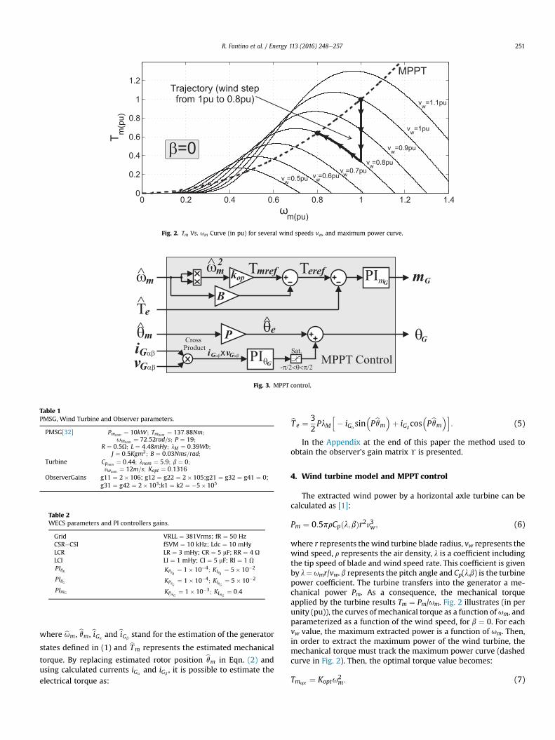
Fig. 2. Tm Vs. um Curve (in pu) for several wind speeds vw, and maximum power curve.
Fig. 3. MPPT control.
Table 1PMSG, Wind Turbine and Observer parameters.
PMSG[32] Pmnom ¼ 10kW ; Tmnom ¼ 137:88Nm;umnom ¼ 72:52rad=s; P ¼ 19;
R ¼ 0:5U; L ¼ 4:48mHy; lM ¼ 0:39Wb;J ¼ 0:5Kgm2; B ¼ 0:03Nms=rad;
Turbine Cpnom ¼ 0:44; lnom ¼ 5:9; b ¼ 0;vwnom ¼ 12m=s; Kopt ¼ 0:1316
ObserverGains g11 ¼ 2� 106; g12 ¼ g22 ¼ 2� 105;g21 ¼ g32 ¼ g41 ¼ 0;g31 ¼ g42 ¼ 2� 103;k1 ¼ k2 ¼ �5� 105
Table 2WECS parameters and PI controllers gains.
Grid VRLL ¼ 381Vrms; fR ¼ 50 HzCSR�CSI fSVM ¼ 10 kHz; Ldc ¼ 10 mHyLCR LR ¼ 3 mHy; CR ¼ 5 mF; RR ¼ 4 ULCI LI ¼ 1 mHy; CI ¼ 5 mF; RI ¼ 1 UPIqR KPqR
¼ 1� 10�4; KIqR¼ 5� 10�2
PIqG KPqG¼ 1� 10�4; KIqG
¼ 5� 10�2
PImG KPmG¼ 1� 10�3; KImG
¼ 0:4
R. Fantino et al. / Energy 113 (2016) 248e257 251
where bum, bqm, biGaandbiGb
stand for the estimation of the generator
states defined in (1) and bTm represents the estimated mechanical
torque. By replacing estimated rotor position bqm in Eqn. (2) andusing calculated currents iGa
and iGb, it is possible to estimate the
electrical torque as:
bTe ¼ 32PlM
h� iGa
sin�Pbqm�þ iGb
cos�Pbqm�i: (5)
In the Appendix at the end of this paper the method used toobtain the observer's gain matrix Y is presented.
4. Wind turbine model and MPPT control
The extracted wind power by a horizontal axle turbine can becalculated as [1]:
Pm ¼ 0:5prCpðl; bÞr2v3w; (6)
where r represents the wind turbine blade radius, vw represents thewind speed, r represents the air density, l is a coefficient includingthe tip speed of blade and wind speed rate. This coefficient is givenby l¼ umr/vw. b represents the pitch angle and Cp(l,b) is the turbinepower coefficient. The turbine transfers into the generator a me-chanical power Pm. As a consequence, the mechanical torqueapplied by the turbine results Tm ¼ Pm/um. Fig. 2 illustrates (in perunity (pu)), the curves of mechanical torque as a function of um, andparameterized as a function of the wind speed, for b ¼ 0. For eachvw value, the maximum extracted power is a function of um. Then,in order to extract the maximum power of the wind turbine, themechanical torque must track the maximum power curve (dashedcurve in Fig. 2). Then, the optimal torque value becomes:
Tmopt ¼ Koptu2m: (7)
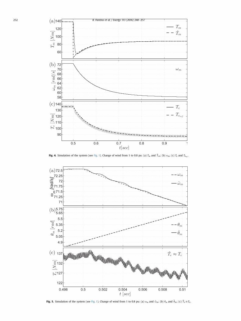
Fig. 4. Simulation of the system (see Fig. 1). Change of wind from 1 to 0.8 pu: (a) Tm and bTm; (b) um; (c) Te and Teref .
Fig. 5. Simulation of the system (see Fig. 1). Change of wind from 1 to 0.8 pu: (a) um and bum; (b) qm and bqm; (c) bTeyTe .
R. Fantino et al. / Energy 113 (2016) 248e257252

R. Fantino et al. / Energy 113 (2016) 248e257 253
The constant value Kopt can be obtained using the turbinenominal data.
The block “MPPT Control” is shown in Fig. 3. This block controlsthe CSR in the WECS shown in Fig. 1. It must be noted that when(dum/dt) ¼ 0 (i.e. steady state) from the PMSG model (Eqn. (1)), thefollowing equation is obtained:
Te���dumdt ¼0
¼ Tm � Bum: (8)
By combining Eqn (7) and (8), and using estimated angularspeed bum (4), the reference electrical torque for MPPT can becalculated as:
Teref ¼ Kopt bu2m � Bbum: (9)
It must be noted that to build this reference the speed estimatedwith the observer was employed, consequently the speed sensor isnot needed. This reference must be tracked to guarantee operationon the maximum power curve. The reference is compared with theestimated electrical torque (Eqn. (5)) and the generated error is a PIinput, whose output is CSRmodulation indexmG, as shown in Fig. 3.
As for CSI (see Fig. 1), a scheme to guarantee that the machinedelivers power satisfying the unity power factor condition is pro-posed. By using estimated rotor position bqm, the internal EMFelectrical angle estimate can be calculated as bqe ¼ Pbqm. This angle isconsidered the initial reference needed for generating the CSRreference angle qG. To achieve unity power factor current injection(iGab
in-phase with vGab), bqe is added to the output of a PI controller
Fig. 6. Simulation of the system (see Fig. 1). Change of win
whose input is given by the cross product between current andvoltage vectors iGab
� vGab(see Fig. 3). Nevertheless, this condition
can be modified to operate with another power factor value [1,29].The block ‘Sat.’ limits the PI output to �p/2<q<p/2.
5. Simulation results
In what follows, simulation results obtained for the systemdescribed in Fig. 1 are shown. These results were obtained withMATLAB®/SIMULINK®/SimPowerSystems® library [33]. The nomi-nal power of the simulated system is Pnom ¼ 10 kW. The PMSG [32],wind turbine and observer parameters are listed in Table 1. Toreduce the simulation time, in order to visualize the dynamicsdetails of the systemvariables, a low value of the moment of inertiaJ was assumed. The parameters of the conversion system (CSR andCSI converters) and LCR and LCI filters are shown in Table 2. The SVMof both converters was implemented with a sample time Ts¼ 1/fSVM[30]. In addition, the parameters of the PI controllers of both con-verters are also shown in Table 2. In a first test, speed wind vw waschanged from 1pu to 0.8pu (from 12 m/s to 9.6 m/s). As a result,wind turbine power Pm decreases abruptly [see (6)]. This leads to adecrease in the mechanical torque, since Tm ¼ Pm/um. Then, theTurbine-PMSG axle decelerates and its speed (um) decreases. Itmust be noted that the speed value is estimated by the observer.Consequently, the reference electrical torque (9) decreases as well(see “Control PMP” Figs. 1 and 3). Then, the controller causes areduction of the electrical torque generated by the PMSG. Thus,extracted current (iq ¼ ½�iGa
sinðPbqmÞ þ iGbcosðPbqmÞ�) is reduced as
d from 1 to 0.8 pu: (a) vGabc; (b) iGabc
; (c) vRabc; (d) iRabc
.

R. Fantino et al. / Energy 113 (2016) 248e257254
well, and simultaneously the mechanical torque is increased. Thistransient behavior ceases when a new steady state point is reached.This new steady state point coincides with the intersection be-tween the turbine torque-speed curve (vw ¼ 0.8 pu) and themaximum power curve. In Fig. 2 the arrowed trajectory shows thedescribed behavior. Figs. 4e6 show the results obtained when awind step was applied. Fig. 4(a) illustrates mechanical torque Tmbehavior and its estimate bTm. There is an error because the me-chanical torque was assumed slowly varying (see Eqn. (3)). How-ever, if necessary, a more complex model can be included. Forinstance, a higher-order mechanical torque derivative term couldbe assumed equal to zero. In such a case, themechanical torquewillbe described by a higher-order dynamical system.
Fig. 4(b) shows the change in mechanical speed um from thenominal value umnom ¼ 72:52rad=s to the steady state valueum ¼ 58.01 rad/s. This value corresponds to the turbine maximumpower point when it operates with a wind speed equal tovw ¼ 0.8 pu (see Fig. 2). In Fig. 4(c), both electrical torque Te and itsreference torque (Eqn. (9)) are shown. It can be seen that the CSRcommutation includes a high frequency ripple in the electricaltorque. In addition, it can be noted that the electrical torqueabruptly decreases at the beginning because the generator active
Fig. 7. (a) Realistic wind speed profile. (b) Actual and estimated mechanical speed. (c
power also decreases. However, the behavior of PImG allows to reachthe new steady state value (Eqn. (8)) close to the mechanical torquevalue.
Actual and estimated values needed to implement the controllaw are shown, in detail, in Fig. 5. In Fig. 5(a) the mechanical speedum and its estimate bum are shown. In Fig. 5(b) rotor position qm andits estimate bqm are shown. In (c) Te and its estimate bT e are shown. Itcan be seen that the observer produces a good estimation of themechanical angle. This angle is used to obtain bT e (Eqn. (5)), then theelectrical torque estimation error is small. The maximum errorbetween the actual mechanical speed and the estimated speed isapproximately 0.1 rad/s. Taking into account that the nominalspeed is 72.52 rad/s, this error is very small. In addition, this error iscorrected by the observer in a short time. Consequently, the controlis not affected in a significative way. Thus, it can be concluded thatthe slowly varying assumption for the mechanical torque does notdeteriorate the control performance.
In Fig. 6(a) grid voltage vGabcis shown; and in Fig. 6(b) the
behavior of three-phase current (iGabc) is shown. In this figure the
thick curves correspond to phase “a” both for the PMSG and thegrid. It can be seen that, after the wind speed step, has been appliedboth PMSG current and voltage value are decreased. The current
) Actual and estimated mechanical torque. d) Electrical torque and its reference.

Fig. 8. Estimation errors: (a) Realistic wind speed profile. (b) Mechanical torque estimation error. (c) Mechanical speed estimation error. (d) Mechanical position estimation error.(e) Electrical torque estimation error.
R. Fantino et al. / Energy 113 (2016) 248e257 255
supplied to the grid is decreased as well. It is obviously a conse-quence of the turbine power reduction. It can be noted that boththe PMSG and the grid operatewith unity power factor, i.e. currentsand voltages are in-phase. It is clear that the system performance isgood and the control strategy used to generate the reference anglesfor CSI and CSR (qR and qG, respectively) works as expected.
In a second test, a realistic wind speed profile is applied to thesystem. Fig. 7(a) shows the wind speed profile. This profile is ob-tained using the von Karman turbulence model [34]. For the timeinterval in which this wind profile is applied, Fig. 7(b), shows theactual and the estimated mechanical speed, Fig. 7(c) shows theactual and the estimated mechanical torque, and 7(d) shows theelectrical torque and its reference. Fig. 8 shows the estimation er-rors. It can be seen that the proposed controller performs very well.Fig. 8(b) shows the mechanical torque error. This error is less than5% of the nominal torque. Meaning that the error provoked byassuming a slowly varying torque is broadly tolerable for thisapplication, and consequently a more complex model is notneeded. In addition, it can be observed that the other estimationerrors are very small.
6. Conclusions
In this work a mechanical sensorless control strategy for a speedvariable WECS based on PMSG was introduced. This strategy usesan extended nonlinear observer to estimate the mechanical vari-ables needed to control the PMSG electrical torque. This torque iscontrolled to track the wind turbine maximum power point.
The main goal behind the proposed strategy is to avoid the useof mechanical sensors in the WECS. This is an important contri-bution to reduce cost and to increase reliability of the system,mainly in WECS including small size power turbine.
Simulations were introduced to show the performance of theproposed system. It was demonstrated that the system perfor-mance is similar to that obtained with controllers that require amechanical sensor.
Acknowledgements
This work was partially supported by UNS, CONICET and ANP-CyT, Argentina.

R. Fantino et al. / Energy 113 (2016) 248e257256
APPENDIX
In this appendix the methodology for designing the observer ispresented. The PMSG model is given by:
266666666664
_qm
_um
iGa
_
iGb
_
Te
377777777775¼
266666666666666666664
um
TmJ� B
Jum � Te
J
�RLiGa
� lML
PumsinðPqmÞ � 1LvGa
�RLiGb
þ lML
PumcosðPqmÞ � 1LvGb
32lMP
h� iGa
sinðPqmÞ þ iGbcosðPqmÞ
i
377777777777777777775
;
_Tm ¼ 0;
y ¼hiGa
iGb
iT:
(10)
In what follows, the following notation will be used: q ¼ Pqm;
u ¼ Pum; ia ¼ iGa; ib ¼ iGb
; va ¼ vGa; vb ¼ vGb
; l0M ¼ PlM; J' ¼ J/P;
B' ¼ B/P.Then, the model can be written as follows:
266666666664
_q
_u
ia_
ib_
Te
377777777775¼
266666666666666666664
u
TmJ0
� B0
J0u� Te
J0
�RLia � l0M
Lu sinq� 1
Lva
�RLib þ
l0ML
u cosq� 1Lvb
32l0M
h� iasinqþ ibcosq
i
377777777777777777775
;
_Tm ¼ 0;
y ¼hia ib
iT:
(11)
In order to design the observer gains and the adaptation law anonlinear transformation is proposed. This transformation is:
x ¼ ½x1 x2 x3 x4 x5�T ¼"l0ML u sinq � l
0ML u cosq ia ib Tm
#T. In the new
coordinates, the PMSG model is represented by
_x ¼ Aexþ rðxÞ þ Vv;y ¼ Cex;
(12)
with Ae ¼�A 00 0
�ε ℝ5�5; Ce ¼ ½C 0� ε ℝ2�5
A ¼
2664�B
0=J
00 0 0
0 �B0=J
00 0
1 0 �R=L 00 1 0 �R=L
3775; C ¼�0 0 1 00 0 1 0
�;
V ¼�0 0 1=L 0 00 0 0 1=L 0
�T.
rðxÞ ¼ ½m1 m2 0 0 0�T ¼�m0
�; m ε ℝ4 (13)8>>>>>>><>>>>>>>:
m1 ¼ m11 þm12x5
¼ �kk1x3x21 � kk1x4x1x2x21 þ x22
�ffiffiffiffiffiffiffiffiffiffiffiffiffiffiffix21 þ x22
qx2k� k
J0
x1ffiffiffiffiffiffiffiffiffiffiffiffiffiffiffix21 þ x22
q x5
m2 ¼ m21 þm22x5
¼ �kk1x4x22 � kk1x3x1x2x21 þ x22
�ffiffiffiffiffiffiffiffiffiffiffiffiffiffiffix21 þ x22
qx1k� k
J0
x2ffiffiffiffiffiffiffiffiffiffiffiffiffiffiffix21 þ x22
q x5
(14)
and k1 ¼ 3f=2J0; k ¼ l0M=L; v ¼ [va vb].
The following observer is proposed for estimating the states inthe transformed coordinates.( _bx ¼ Ae
bx þ r�bx�þ Vv þ Geðy � byÞ þ lae;
y ¼ Cebx; (15)
where Ge ¼ ½G 0�T ; G ε ℝ4�2; lae ¼ [0 la]T; la ε ℝ is the adaptationlaw.
ex ¼ x� bx;_ex ¼
�A� GC 0
0 0
�exi þ Dr� lae;
(16)
with Dr ¼ rðxÞ � r�bx� ¼
�Dm0
�; Dm ε ℝ4
Dm ¼
266664Dm11 þ Dm12x5 þ Dm12
�bx�ex5Dm21 þ Dm22x5 þ Dm22
�bx�ex500
377775: (17)
The adaptation law and the gain matrix must be chosen toguarantee the convergence to zero of the estimation error. A Lya-punov candidate function is chosen. This function is given by:
V ¼ eTxPe ex; Pe ¼�P 00 I
�: (18)
The Laypunov function time derivative results
_V ¼ eTn�ATc P þ PAc
�en þ 2eTnPDm� 2laex5
en ¼hex1 ex2 ex3 ex4
iT; Ac ¼ ðA� GCÞ:
(19)
By choosing matrix Q to satisfy the following Lyapunov equation
ATc P þ PAc ¼ �Q ; Q >0; (20)
then, the following equality is obtained.
_V ¼ �eTnQ en þ 2eTnPDm� 2laex5 : (21)
This equation suggests to use the following adaption law:
la ¼ hT ðbxÞP en; con hT ¼ [m12 m22 0 0]. Then, the followinginequality is satisfied for the Lyapunov function time derivative
_V � ð � qþ 2pL1 þ 2pL2jjx5jjÞ������en������2: (22)

R. Fantino et al. / Energy 113 (2016) 248e257 257
In this inequality, q is the minimum eigenvalue of Q; p is themaximum eigenvalue of P; L1 and L2 are the Lipschitz constant ofm1 and m2, respectively.
By assuming that jjx5jj is bounded, whens ¼ �qþ 2pL1 þ 2pL2jjx5jj<0 the estimation error converges tozero. It must be noted that ex1 and ex2 cannot be used in theadaptation law, because x1 and x2 are not measurable. In originalcoordinates, the adaptation law built from the measured variablesresults:
l0a ¼ �k1sin
�Pbqm��ia �bia�þ k2cos
�Pbqm��ib �bib�: (23)
Then, coming back to the original coordinates the observerdescription is given by (4).
References
[1] Wu B, Lang Y, Zargari N, Kouro S. Power conversion and control of wind en-ergy systems. Wiley-IEEE Press; 2011.
[2] Nguyen TH, Lee D-C. A novel current control scheme of grid converters forsmall pmsg wind turbines under grid voltage distortion. In: Power electronicsand machines in wind applications (PEMWA), 2012 IEEE; July 2012. p. 1e6.
[3] Espinoza J, Joos G. A current-source-inverter-fed induction motor drive sys-tem with reduced losses. Ind Appl IEEE Trans 2012:1e6.
[4] Enjeti P, Ziogas P, Lindsay J. A current source pwm inverter with instanta-neous current control capability. Ind Appl IEEE Trans 1991;27:582e8.
[5] Phillips KP. Current-source converter for ac motor drives. Ind Appl IEEE Trans1979;IA-8:445e52.
[6] Dai J, Xu D, Wu B. A novel control scheme for current-source-converter-basedpmsg wind energy conversion systems. Power Electron IEEE Trans April2009;24:963e72.
[7] Nikolic A, Jeftenic B. Current source converter topologies for pmsg wind tur-bine applications. In: Power electronics and motion control conference (EPE/PEMC), 2010 14th international; Sept 2010. S14e27. S14e32.
[8] Popat M, Wu B, Zargari N. A novel decoupled interconnecting method forcurrent-source converter-based offshore wind farms. Power Electron IEEETrans Oct 2012;27:4224e33.
[9] Yin X-x, Lin Y-g, Li W, Gu Y-j, Liu H-w, Lei P-f. A novel fuzzy integral slidingmode current control strategy for maximizing wind power extraction andeliminating voltage harmonics. Energy 2015;85:677e86.
[10] Alizadeh M, Shokri Kojori S. Augmenting effectiveness of control loops of apmsg (permanent magnet synchronous generator) based wind energy con-version system by a virtually adaptive pi (proportional integral) controller.Energy 2015;91:610e29.
[11] Elnaggar M, Abdel Fattah H, Elshafei A. Maximum power tracking in wecs(wind energy conversion systems) via numerical and stochastic approaches.Energy 2014;74:651e61.
[12] Belmokhtar K, Doumbia M, Agbossou K. Novel fuzzy logic based sensorlessmaximum power point tracking strategy for wind turbine systems driven dfig(doubly-fed induction generator). Energy 2014;76:679e93.
[13] Inoue Y, Morimoto S, Sanada M. Control method for direct torque controlledpmsg in wind power generation system. In: Electric machines and drivesconference, 2009. IEMDC ’09. IEEE international; May 2009. p. 1231e8.
[14] Zhang Z, Zhao Y, Qiao W, Qu L. A space-vector-modulated sensorless direct-torque control for direct-drive pmsg wind turbines. Ind Appl IEEE Trans July
2014;50:2331e41.[15] Orlando N, Liserre M, Monopoli V, Dell’Aquila A. Speed sensorless control of a
pmsg for small wind turbine systems. In: Industrial electronics, 2009. ISIE2009. IEEE international symposium on; July 2009. p. 1540e5.
[16] Abdelkafi A, Krichen L. New strategy of pitch angle control for energy man-agement of a wind farm. Energy 2011;36:1470e9.
[17] Hossain MM, Ali MH. Future research directions for the wind turbine gener-ator system. Renew Sustain Energy Rev 2015;49:481e9.
[18] Orlando NA, et al. A survey of control issues in pmsg-based small wind-turbine systems. Ind Inf IEEE Trans 2013;9(3):1211e21.
[19] Thongam J, Bouchard P, Beguenane R, Fofana I, Ouhrouche M. Sensorlesscontrol of pmsg in variable speed wind energy conversion systems. In: Powerelectronics conference (IPEC), 2010 international; June 2010. p. 2254e9.
[20] Huang K, Zheng L, Huang S, Xiao L, Li W. Sensorless control for direct-drivepmsg wind turbines based on sliding mode observer. In: Electrical machinesand systems (ICEMS), 2011 international conference on; Aug 2011. p. 1e5.
[21] Liu W, Chen L, Ou J, Cheng S. Simulation of pmsg wind turbine system withsensor-less control technology based on model reference adaptive system. In:Electrical machines and systems (ICEMS), 2011 international conference on;Aug 2011. p. 1e3.
[22] Chou Y, Nian H. Sensorless control of pmsg based on dual two-level inverteropen winding configuration for wind turbines. In: Electrical machines andsystems (ICEMS), 2012 15th international conference on; Oct 2012. p. 1e6.
[23] Jaramillo-Lopez F, Kenne G, Lamnabhi-Lagarrigue F. A novel online trainingneural network-based algorithm for wind speed estimation and adaptivecontrol of pmsg wind turbine system for maximum power extraction. RenewEnergy 2016;86:38e48.
[24] Urtasun A, Sanchis P, San Martín I, L�opez J, Marroyo L. Modeling of small windturbines based on pmsg with diode bridge for sensorless maximum powertracking. Renew energy 2013;55:138e49.
[25] Urtasun A, Sanchis P, Marroyo L. Small wind turbine sensorless mppt:robustness analysis and lossless approach. Ind Appl IEEE Trans 2014;50(6):4113e21.
[26] Aubr�ee R, Auger F, Mac�e M, Loron L. Design of an efficient small wind-energyconversion system with an adaptive sensorless mppt strategy. Renew Energy2016;86:280e91.
[27] Lon�carek T, Le�si�c V, Va�sak M. Increasing accuracy of kalman filter-basedsensorless control of wind turbine pm synchronous generator. In: Industrialtechnology (ICIT), 2015 IEEE international conference on; March 2015.p. 745e50.
[28] Solsona J, Valla M, Muravchik C. Nonlinear control of a permanent magnetsynchronous motor with disturbance torque estimation. Energy Convers IEEETrans Jun 2000;15:163e8.
[29] Dai J, Xu D, Wu B. A novel control system for current source converter basedvariable speed pm wind power generators. In: Power electronics specialistsconference, 2007. PESC 2007. IEEE; 2007. p. 1852e7.
[30] Pham D, Huang S, Huang K. Modeling and simulation of current source in-verters with space vector modulation. In: Electrical machines and systems(ICEMS), 2010 international conference on; Oct 2010. p. 320e5.
[31] Orando N, Mastromauro R, Liserre M, Dell’Aquila A. Grid voltage support bymeans of a small wind turbine system. In: Industrial electronics, 2008. IECON2008. 34th annual conference of IEEE; Nov 2008. p. 2178e83.
[32] Shariatpanah H, Fadaeinedjad R, Rashidinejad M. A new model for pmsg-based wind turbine with yaw control. IEEE Trans Energy Convers Dec2013;28:929e37.
[33] MATLAB®, version 8.1.0.604 (R2013a). Natick, Massachusetts: The MathWorksInc; 2013.
[34] Nichita C, Luca D, Dakyo B, Ceanga E. Large band simulation of the wind speedfor real time wind turbine simulators. Energy Convers IEEE Trans 2002;17(4):523e9.