norgren pneumatic valve products -...
TRANSCRIPT

Littleton, CO USA Phone: 303-794-2611 www.norgren.com VAL-Intro
APC-102October 2002
Supersedes 6/01
ContentsValve Overview . . . . . . . . . . . . . . . . . . . . . . . . . . . . . . . . . . .VAL-2VM10 Series Valves . . . . . . . . . . . . . . . . . . . . . . . . . . . . . .VAL1-1V20, V22, and VE2 Series Fieldbus . . . . . . . . . . . . . . . . . .VAL-2-1V60/62 Series Valves . . . . . . . . . . . . . . . . . . . . . . . . . . . . .VAL-3-1Mini ISO Star Valves . . . . . . . . . . . . . . . . . . . . . . . . . . . . .VAL-4-1ISO Star Series Valves . . . . . . . . . . . . . . . . . . . . . . . . . . .VAL-5-1Nugget 30 Series Valves . . . . . . . . . . . . . . . . . . . . . . . . . .VAL-6-1Super X Series Valves . . . . . . . . . . . . . . . . . . . . . . . . . . . .VAL-7-1Nugget 40 Series Valves . . . . . . . . . . . . . . . . . . . . . . . . . .VAL-8-1Nugget 120 Series Valves . . . . . . . . . . . . . . . . . . . . . . . . .VAL-9-1Nugget 200 Series Valves . . . . . . . . . . . . . . . . . . . . . . . .VAL-10-1Nugget 500 Series Valves . . . . . . . . . . . . . . . . . . . . . . . .VAL-11-1Prospector Series Poppet Valves . . . . . . . . . . . . . . . . . .VAL-12-1Fittings and Accessories . . . . . . . . . . . . . . . . . . . . . . . .VAL-13-1
Norgren PneumaticValve Products

Norgren Valve Products
VAL-Intro Littleton, CO USA Phone: 303-794-2611 www.norgren.com
VM10 Series Valves (See VAL-1)Port SIzes: Port fittings of 1/8, 5/32, 1/4, (3 mm, 4 mm, 6 mm)Flow: Cv of 0.36 to 0.44Valve Type: 2 x 3/2, 5/2 and 5/3 with integral push-in fittingsElectrical Connections: 2-pin individually wired, 25 and 44-pin D connector,
Fieldbus, and ASISubbase Mounting: DIN rail brackets, through hole brackets, or threaded screw
mountOperator Types: Solenoid pilot spool valve
Nugget 30 Series Valves (See VAL-6)Port SIze: Port fittings in 5/32", 1/4", 4 mm, or 6 mmFlow: Cv of .27Valve Type: 5-port/2-position and 5-port/3-positionElectrical Connections: 25-pin D connector and plug-in wireway, or pinch plugs
with leadsSubbase Mounting: lightweight plastic manifolding subbase with plug-on
common wireway and 25-pin D connector provides up to 24 stations, orAluminum fixed length 10-32 UNF ported subbase (1 to 12 stations).
Operator Types: Solenoid pilotFieldbus Compatible
ISO Star Series Valves (See VAL-5)Port Size: 1/4" (size 1), 3/8" (size 2), 1/2" (size 3), NPT or ISO GFlow: Cv of 1.2, 2.4, 4.0Valve Type: 5-port/2-position and 5-port/3-positionMounting Options: single subbase, or manifolding subbaseOperator Types: Solenoid pilot, or air pilotElectrical Connections: Cable grip standard. Optional: electrical connectors are
cable grip with indicator light, a 1/2" NPT conduit connector, 6-foot, three-conductor molded cable, and 6-foot, three-conductor molded cable withsurge suppression, reverse polarity protection, and indicator light.
Mini ISO Star Series Valves (See VAL-4)Port Size: ISO 15407-1/VDMA 24 563, 18 and 26 mmFlow: Cv of 0.92, 1.22, 1.17Valve Type: 5-port/2-position, 5-port/3-position, dual 3-post/2-positionMounting Options: Single or manifolding subbaseOperator Types: Solenoid pilot, or air pilotElectrical Connections: Cable grip standard. Optional: electrical connectors are
cable grip with indicator light, a 1/2" NPT conduit connector, 10-footmolded cable, and 10-foot molded cable with surge suppression, reversepolarity protection, and indicator light.
V20 & V22 and Fieldbus II (See VAL-2)Port Size: 1/8" and 1/4" NPT or ISO GFlow: Cv of 0.41 to 1.17Valve Type: 5-port/2-position, 5-port/3-position, dual 3-port/2-position (in one
body)Mounting options: Modular manifold up to 20-stationsCommon Wireway Electrical Connections: 25-pin 'D' sub connector and 1"
NPT conduitFieldbus I/O capability: 128 I/O per nodeFieldbus Protocols: DeviceNet, Profibus-DP, Interbus-S, CANOpen,
and AS-Interface
V60/62 Series Valves (See VAL-3)Port SIze: 1/8" to 3/8" NPT, and ISO GFlow: Cv of 0.75 to 4.2Valve Type: 3-port/2-position, 5-port/2-position, and 5-port/3-position, and
modular fixed length manifold 2 x 3-port/2-positionMounting Options: Two through holes for wall or control cabinet mountingOperator Types: Solenoid and pilot actuatedElectrical Connections: DIN 43650 Table “B”

Norgren Valve Products
Littleton, CO USA Phone: 303-794-2611 www.norgren.com VAL-Intro
Super X Series Valves (See VAL-7)Port SIze: 1/8" and 1/4" NPTFlow: 1/8" (Cv of .34), 1/4" (Cv of .98)Valve Type: 3-port/2-position, 5-port/2-position, and 5-port/3-positionMounting Options: Two through holes for wall or control cabinet mounting.
Many operators are available for panel mounting.Operator Types: Manual or mechanical
Nugget 40 Series Valves (See VAL-8)Port SIze: Inline ports - 10-32 UNF
Subbase ports - 1/8" NPTEndplate ports - 1/4" NPT (inlet), 1/8" NPT (exhaust)
Flow: Inline - Cv of .26, subbase Cv of .41Valve Type: 3-port/2-position, 5-port/2-position, and 5-port/3-positionMounting Options: Inline, inline on a fixed length manifold, inline modular, single
subbase valve, and subbase-modular manifoldsElectrical Connections: 25-pin D connector, or 1" conduit electrical connectionOperator Types: Solenoid pilot or air pilotFieldbus Compatible
Nugget 120 Valves Series Valves (See VAL-9)Port SIze: Subbase ports - 1/4" NPT
Subbase endplates - 3/8" NPT (inlet), 1/4" (exhaust)Flow: 3/2 and 5/2 Cv of 1.17, 5/3 Cv of 0.79Valve Type: 3-port/2-position, 5-port/2-position, and 5-port/3-positionMounting Options: Subbase valve - through holes to subbase and manifold
Manifold mounted - through holes in end plate or to a 35 mm DIN rail
Operator Types: Solenoid pilot or air pilotElectrical Connections: 25-pin D connector, or 1" conduit electrical connectionFieldbus Compatible
Nugget 200 Series Valves (See VAL-10)Port SIze: 1/4", 3/8", or 1/2" NPT or ISO GFlow: Cv of 1.6Valve Type: 3-port/2-position*, 5-port/2-position, and 5-port/3-positionMounting Options: Inline valves, stacking valve assembly, stacking valve
assembly with junction box, or inline fixed length manifold.Operator Types: Solenoid pilot, air pilot, manual, or mechanicalElectrical Connections: DIN 43650 Table “B”, 1/2" NPT conduit connector, or
1" conduit (junction box)*Not available in 1/2" ports
Nugget 500 Series Valves (See VAL-11)Port Size: 3/8", or 1/2" NPT or ISO G, and 3/4" ports NPT (inline valves only)Flow: Cv of 5.0Valve Type: 5-port/2-position and 5-port/3-positionMounting Options: Inline have two sets of mounting holes through the body.
Fixed length manifolds, single subbase, and subbase valves attached to amanifolding subbase.
Operator Types: Solenoid pilot or air pilotElectrical Connector Options: cable grip with indicator light, a 1/2" NPT conduit
connector and a 5-foot, three-conductor, molded cable connector with orwithout indicator light and surge suppression.
Prospector Series Poppet Valves (See VAL-12)Port Size: 1/4" through 2"Flow: Cv of 2.1 to 49.5Valve Type: 2-port/2-position, 3-port/2-position, 4-port/2-position, and
3-port/2-position multi-directionalMounting Options: Inline or single subbase Operator Types: Solenoid pilot, air pilot, manual, or mechanicalElectrical Connector Options: cable grip with indicator light, a 1/2" NPT conduit
connector and a 5-foot, three-conductor, molded cable connector with orwithout indicator light and surge suppression.
Littleton, CO USA Phone: 303-794-2611 www.norgren.com VAL-1-1
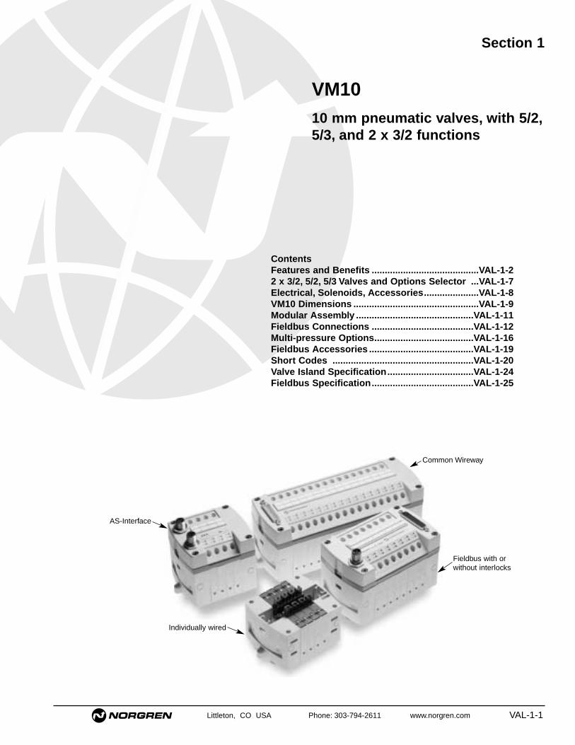
Section 1
ContentsFeatures and Benefits .........................................VAL-1-22 x 3/2, 5/2, 5/3 Valves and Options Selector ...VAL-1-7Electrical, Solenoids, Accessories.....................VAL-1-8VM10 Dimensions ................................................VAL-1-9Modular Assembly .............................................VAL-1-11Fieldbus Connections .......................................VAL-1-12Multi-pressure Options......................................VAL-1-16Fieldbus Accessories ........................................VAL-1-19Short Codes ......................................................VAL-1-20Valve Island Specification.................................VAL-1-24Fieldbus Specification.......................................VAL-1-25
VM1010 mm pneumatic valves, with 5/2,5/3, and 2 x 3/2 functions
Common Wireway
Fieldbus with or without interlocks
AS-Interface
Individually wired

Valve Islands, VM10 Series
VAL-1-2 Littleton, CO USA Phone: 303-794-2611 www.norgren.com
• Save time with Norgren's unique easy-to-use valve island configurator,available either online or on CD
• Easy to configure up to 20 stations (40 coils)
Configure the unit that exactly meets your needs from: • 260 valve options per station, including 5/2, 5/3 and
2 x 3/2 functions• 7 fitting sizes per valve• Individually wired, Multipole or Fieldbus• Internal or external pilot• With or without checked exhaust flow paths• 4 inlet/exhaust fitting sizesgiving you more than 7 million possible configurations
• Viewable/downloadable 2D and 3D CAD drawings in 13 file formats• Downloadable multi-language technical and dimensional information• List price automatically calculated for complete valve islands
Easy to select and configureVM10
Valve Islands, VM10 Series
Littleton, CO USA Phone: 303-794-2611 www.norgren.com VAL-1-3
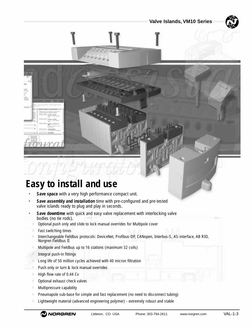
Easy to install and use• Save space with a very high performance compact unit.
• Save assembly and installation time with pre-configured and pre-tested valve islands ready to plug and play in seconds.
• Save downtime with quick and easy valve replacement with interlocking valve bodies (no tie rods).
◊ Optional push only and slide to lock manual overrides for Multipole cover◊ Fast switching times◊ Interchangeable Fieldbus protocols: DeviceNet, Profibus-DP, CANopen, Interbus-S, AS-interface, AB RIO,
Norgren Fieldbus II◊ Multipole and Fieldbus up to 16 stations (maximum 32 coils)◊ Integral push-in fittings◊ Long life of 50 million cycles achieved with 40 micron filtration◊ Push only or turn & lock manual overrides◊ High flow rate of 0.44 Cv◊ Optional exhaust check valves◊ Multipressure capability◊ Pneumapole sub-base for simple and fast replacement (no need to disconnect tubing)◊ Lightweight material (advanced engineering polymer) - extremely robust and stable

Valve Islands, VM10 Series
VAL-1-4 Littleton, CO USA Phone: 303-794-2611 www.norgren.com
• The versatility of VM10 makes it highly suitable for many different industry sectors and applicationsincluding electronics, packaging and textile machinery and a wide variety of special purpose machines.
Easy to apply
Suitable for packaging machinery
• High flow rate of 0.44 Cv from a 10 mm valve
• NEMA 4, IP65 protection rating
• High resistance to chemical washdowns
• Available in all major Fieldbus protocols
Suitable for electronics manufacturing
• Backed by a reliability test specification conformingto SEMI E10
• Up to 30% space saving in Fieldbus applications compared to other equivalent products. (Electronics fit in the same envelope size as astandard Multipole valve island)
• Clean, sleek design• 2 x 3/2 function for piloting process valves• Electronics grade cleaning and packaging options

Valve Islands, VM10 Series
Littleton, CO USA Phone: 303-794-2611 www.norgren.com VAL-1-5
Suitable for textile machinery
• Individually wired, Multipole and Fieldbus options
• Save space: 2 x 3/2 in single slice for control ofsingle acting actuators
• Multi-pressure options
And many other applications
• High resistance to chemicals even with prolongedcontact (eg food industry)
• Exceptional dimensional stability even in humidenvironments (eg paper industry)
• Excellent hydrolysis resistance even with hot water
• Low weight (eg robotics and end of arm tooling)

VAL-1-6 Littleton, CO USA Phone: 303-794-2611 www.norgren.com
Valve islands, VM10 Series
● Multipole or individually wired for installation
flexibility
● Interchangeable Fieldbus compatible modules
● Compact and lightweight
● Standard or checked exhaust paths
● Quick disconnect base (Pneumapole)
● High flow from 10 mm valve width
Valve slices 2 x 3/2, 5/2 and 5/3with integral push-in fittings
Technical dataMedium:Compressed air, filtered, lubricated and non-lubricatedOperation:Solenoid pilot spool valvePort sizes:Push-in fittings of 1/8, 5/32, 1/4, 3 mm, 4 mm, 6 mmOperating pressure:Maximum 116 psig (8 bar)Flow:Function Cv ‘C’ b’ ‘A’ l/min Kv5/2 port 1 to 2 & 4 0.44 1.77 0.48 7.10 430 0.365/2 ports 2 to 3 & 4 to 5 0.41 1.65 0.45 6.61 400 0.343/2 ports 1 to 2 & 1 to 4 0.36 1.44 0.39 5.78 350 0.293/2 ports 2 to 3 & 4 to 5 0.36 1.44 0.39 5.78 350 0.295/3 ports 1 to 2 & 4 0.36 1.44 0.39 5.78 350 0.295/3 ports 2 to 3 & 4 to 5 0.36 1.44 0.39 5.78 350 0.29Degree of protection:NEMA 4 and IP65Ambient temperature:4°F to 122°F (-20°C to +50°C)For use below 36°F (+2°C) consult our Technical Service
Materials Aluminum spool with nitrile rubber sealsBody, end plates: engineered PPA co-polymer
Ordering informationTo order please use valve island configuratoravailable at www.norgren.comAlternatively contact Norgren for a configuratoron CD
Valve Islands, VM10 Series
Littleton, CO USA Phone: 303-794-2611 www.norgren.com VAL-1-7
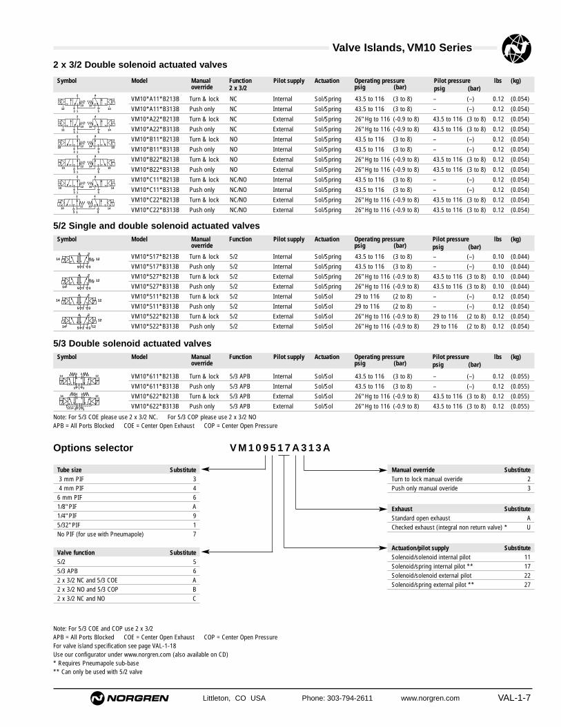
Symbol Model Manualoverride
Function2 x 3/2
Pilot supply Actuation Operating pressurepsig (bar)
Pilot pressure psig (bar)
lbs (kg)
VM10*A11*B213B Turn & lock NC Internal Sol/Spring 43.5 to 116 (3 to 8) – (–) 0.12 (0.054)
VM10*A11*B313B Push only NC Internal Sol/Spring 43.5 to 116 (3 to 8) – (–) 0.12 (0.054)
VM10*A22*B213B Turn & lock NC External Sol/Spring 26" Hg to 116 (-0.9 to 8) 43.5 to 116 (3 to 8) 0.12 (0.054)
VM10*A22*B313B Push only NC External Sol/Spring 26" Hg to 116 (-0.9 to 8) 43.5 to 116 (3 to 8) 0.12 (0.054)
VM10*B11*B213B Turn & lock NO Internal Sol/Spring 43.5 to 116 (3 to 8) – (–) 0.12 (0.054)
VM10*B11*B313B Push only NO Internal Sol/Spring 43.5 to 116 (3 to 8) – (–) 0.12 (0.054)
VM10*B22*B213B Turn & lock NO External Sol/Spring 26" Hg to 116 (-0.9 to 8) 43.5 to 116 (3 to 8) 0.12 (0.054)
VM10*B22*B313B Push only NO External Sol/Spring 26" Hg to 116 (-0.9 to 8) 43.5 to 116 (3 to 8) 0.12 (0.054)
VM10*C11*B213B Turn & lock NC/NO Internal Sol/Spring 43.5 to 116 (3 to 8) – (–) 0.12 (0.054)
VM10*C11*B313B Push only NC/NO Internal Sol/Spring 43.5 to 116 (3 to 8) – (–) 0.12 (0.054)
VM10*C22*B213B Turn & lock NC/NO External Sol/Spring 26" Hg to 116 (-0.9 to 8) 43.5 to 116 (3 to 8) 0.12 (0.054)
VM10*C22*B313B Push only NC/NO External Sol/Spring 26" Hg to 116 (-0.9 to 8) 43.5 to 116 (3 to 8) 0.12 (0.054)
2 x 3/2 Double solenoid actuated valves
3 1 5
2 4
12 1410 10
3 1 5
2 4
12 1410 10
3 1 5
2 4
12 1010 14
3 1 5
2 4
12 1010 14
3 1 5
2 4
10 101412
3 1 5
2 4
10 101412
VM10*517*B213B Turn & lock 5/2 Internal Sol/Spring 43.5 to 116 (3 to 8) – (–) 0.10 (0.044)
VM10*517*B313B Push only 5/2 Internal Sol/Spring 43.5 to 116 (3 to 8) – (–) 0.10 (0.044)
VM10*527*B213B Turn & lock 5/2 External Sol/Spring 26" Hg to 116 (-0.9 to 8) 43.5 to 116 (3 to 8) 0.10 (0.044)
VM10*527*B313B Push only 5/2 External Sol/Spring 26" Hg to 116 (-0.9 to 8) 43.5 to 116 (3 to 8) 0.10 (0.044)
VM10*511*B213B Turn & lock 5/2 Internal Sol/Sol 29 to 116 (2 to 8) – (–) 0.12 (0.054)
VM10*511*B313B Push only 5/2 Internal Sol/Sol 29 to 116 (2 to 8) – (–) 0.12 (0.054)
VM10*522*B213B Turn & lock 5/2 External Sol/Sol 26" Hg to 116 (-0.9 to 8) 29 to 116 (2 to 8) 0.12 (0.054)
VM10*522*B313B Push only 5/2 External Sol/Sol 26" Hg to 116 (-0.9 to 8) 29 to 116 (2 to 8) 0.12 (0.054)
5/2 Single and double solenoid actuated valves
4 214
5 1 3
12
4 2
5 1 3
12
14 12
4 2
12
14 5 1 3
4 2
1214
5 1 3
VM10*611*B213B Turn & lock 5/3 APB Internal Sol/Sol 43.5 to 116 (3 to 8) – (–) 0.12 (0.055)
VM10*611*B313B Push only 5/3 APB Internal Sol/Sol 43.5 to 116 (3 to 8) – (–) 0.12 (0.055)
VM10*622*B213B Turn & lock 5/3 APB External Sol/Sol 26" Hg to 116 (-0.9 to 8) 43.5 to 116 (3 to 8) 0.12 (0.055)
VM10*622*B313B Push only 5/3 APB External Sol/Sol 26" Hg to 116 (-0.9 to 8) 43.5 to 116 (3 to 8) 0.12 (0.055)
5/3 Double solenoid actuated valves
4
5 1 3
2
12/14
1214
4
5 1 3
214 12
Note: For 5/3 COE please use 2 x 3/2 NC. For 5/3 COP please use 2 x 3/2 NOAPB = All Ports Blocked COE = Center Open Exhaust COP = Center Open Pressure
Symbol Model Manualoverride
Function Pilot supply Actuation Operating pressure psig (bar)
Pilot pressure psig (bar)
lbs (kg)
Symbol Model Manualoverride
Function Pilot supply Actuation Operating pressurepsig (bar)
Pilot pressure psig (bar)
lbs (kg)
V M 1 0 9 5 1 7 A 3 1 3 A
Valve function Substitute5/2 55/3 APB 62 x 3/2 NC and 5/3 COE A2 x 3/2 NO and 5/3 COP B2 x 3/2 NC and NO C
Tube size Substitute3 mm PIF 34 mm PIF 4
6 mm PIF 61/8" PIF A1/4" PIF 95/32" PIF 1No PIF (for use with Pneumapole) 7
Manual override SubstituteTurn to lock manual overide 2Push only manual overide 3
Exhaust SubstituteStandard open exhaust AChecked exhaust (integral non return valve) * U
Actuation/pilot supply SubstituteSolenoid/solenoid internal pilot 11Solenoid/spring internal pilot ** 17Solenoid/solenoid external pilot 22Solenoid/spring external pilot ** 27
Options selector
Note: For 5/3 COE and COP use 2 x 3/2APB = All Ports Blocked COE = Center Open Exhaust COP = Center Open PressureFor valve island specification see page VAL-1-18Use our configurator under www.norgren.com (also available on CD)* Requires Pneumapole sub-base** Can only be used with 5/2 valve

Valve Islands, VM10 Series
VAL-1-8 Littleton, CO USA Phone: 303-794-2611 www.norgren.com
V11569-E01 3 ft (1m) L1 V11570-E01 3 ft (1m) M4 V11568-E01 3 ft (1m) K1 VM106517AQ0300 2AV11569-E03 10 ft (3m)L2 V11570-E03 10 ft (3m) M5 V11568-E03 10 ft (3m) K2V11569-E05 16 ft (5m)L3 V11570-E05 16 ft (5m) M6 V11568-E05 16 ft (5m) K3
VM106517AQ0301 Port 1 blocked 2BVM106517AQ0302 Ports 3 & 5 blocked 2CVM106517AQ0303 Ports 1, 3 &5 blocked 2D
Accessories for individually wired and multipole valve islands
D Sub-connector 25 pin D Sub-connector 44 pin 2 Pin connector Valve blanking station Port blocking station
VM106517AQ0804 4 mm 7A V10009-C00 3 ft (1m) A17 V11554-K30 8DVM106517AQ0806 6 mm 7B
V11574-K30 Push only N1V11574-K31 Slide to lock N2
Pressure switch DIN Rail DIN Rail fixing kit Manual override kit Pneumapole sub-base
Voltage: 24 V d.c. 0.6 WSurge suppression: Flywheel diodeIndication: Yellow LED
Electrical details
SolenoidsVoltage tolerance: ± 10%Rating: 100% ED
For part numbers and dimensional detailssee page VAL-1-15

Valve Islands, VM10 Series
Littleton, CO USA Phone: 303-794-2611 www.norgren.com VAL-1-9
4 6 6 66
1
2
2
0.59 (15)1.26 (32)
0.41
(10
.5)
2.09
(53
)0.
37 (
9.5)
3.11 (79)
0.59 (15)1.26 (32)
0.41
(10
.5)
4 6 6 66
1
2
2
2.09
(53
)0.
37 (
9.5)
3.11 (79)
VM10 models
Singlesolenoid
Doublesolenoid
Blankingplates
Port blocking station
2.20
(56
)
3.11 (79)
0.41
(10
.5)
VM106517AQ0300 Ports 1, 3 & 5 open 2AVM106517AQ0301 Port 1 blocked 2BVM106517AQ0302 Ports 3 & 5 blocked 2CVM106517AQ0303 Ports 1, 3 &5 blocked 2D
All dimensions in inches (mm)

Valve Islands, VM10 Series
VAL-1-10 Littleton, CO USA Phone: 303-794-2611 www.norgren.com
32
12/14
2223
11
544446
5
6
66
66
66
666
6666
6
12/1482/84
82/84
1.10 (28)
0.73 (18.5)
0.57 (14.5)
0.49 (12.5)0.19 (4.9)
0.39
(10
)
0.96
(24
.5)
1.56
(39
.5)
2.15
(54
.5)
2.72
(69
)
A
B
D
M4
0.41 (10.5)
(N x 0.41 (10.5) ) + 2.59 (65.7)
0.19 (4.9)
0.12 (3)
0.39 (10)
2.09 (53)
1.26
(32
)0.
59 (
15)
3.11
(79
)
Port connections
End Plate KitModel Number
Description Shortcode
B APorts 1 ,3 & 5 Ports 12/14 & 82/84
VM106517AQ0202 End plate kit - feed both ends 3/8" 1/4" 1GVM106517AQ020X End plate kit - feed both ends 5/16" 5/32" 1HVM106517AQ0212 End plate kit - feed left, right blocked 3/8" 1/4" 1JVM106517AQ021X End plate kit - feed left, right blocked 5/16" 5/32" 1KVM106517AQ0222 End plate kit - feed right, left blocked 3/8" 1/4" 1LVM106517AQ022X End plate kit - feed right, left blocked 5/16" 5/32" 1MVM106517AQ0231 End plate kit - feed both ends No PIF* No PIF* 1SVM106517AQ0232 End plate kit - feed left, right blocked No PIF*) No PIF* 1TVM106517AQ0233 End plate kit - feed right, left blocked No PIF*) No PIF* 1VVM106517AQ010Y End plate kit - feed both ends 10 mm 6 mm 1AVM106517AQ0108 End plate kit - feed both ends 8 mm 4 mm 1BVM106517AQ011Y End plate kit - feed left, right blocked 10 mm 6 mm 1CVM106517AQ0118 End plate kit - feed left, right blocked 8 mm 4 mm 1DVM106517AQ012Y End plate kit - feed right, left blocked 10 mm 6 mm 1EVM106517AQ0128 End plate kit - feed right, left blocked 8 mm 4 mm 1FVM106517AQ0131 End plate kit - feed both ends No PIF* No PIF* 1NVM106517AQ0132 End plate kit - feed left, right blocked No PIF* No PIF* 1PVM106517AQ0133 End plate kit - feed right, left blocked No PIF*) No PIF* 1R
Available valve port sizes – Ø 1/8, 5/32, 1/4, 3 mm, 4 mm, 6 mm* No push in fitting for use with pneumapole sub-base
Ports 82/84
Ports 1, 3 & 5
Ports 12/14
N = number of stations
Detailed CAD drawings available through website valve island configurator
All dimensions in inches (mm)

Valve Islands, VM10 Series
Littleton, CO USA Phone: 303-794-2611 www.norgren.com VAL-1-11
Modular assembly
2 Pin connector 2 to 20 40
Individually wired No. stations Max. No. coils
Individually wired
25 Pin connector 04 VM106517AQ0404 8 A125 Pin connector 06 VM106517AQ0406 12 A225 Pin connector 08 VM106517AQ0408 16 A325 Pin connector 10 VM106517AQ0410 20 A425 Pin connector 12 VM106517AQ0412 24 A544 Pin connector 10 VM106517AQ0510 20 B144 Pin connector 12 VM106517AQ0512 24 B244 Pin connector 16 VM106517AQ0516 32 B3
Multipole
2.09 (53)
2.22 (56.5)
0.37 (9.5)
(N x 0.41 (10.5) ) + 2.59 (65.7)
0.41 (10.5)1.30 (33)
3.11
(79
)
3.27 (83)
3.41 (86.5)
0.41 (10.5)1.50 (38)
3.13 (79.5)
3.11
(79
)
(N x 0.41 (10.5) ) + 2.59 (65.7)
N = number of stations
N = number of stations
25 Pin connector for 4, 6, 8, 10 & 12 station44 Pin connector for 10, 12 & 16 station
Multipole ModelNo. stations Max. no. coils Short code
All dimensions in inches (mm)

Valve Islands, VM10 Series
VAL-1-12 Littleton, CO USA Phone: 303-794-2611 www.norgren.com
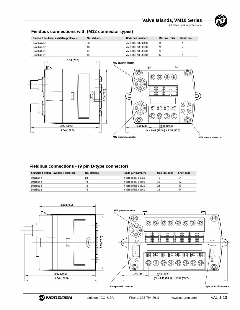
Fieldbus connections (M12 connector types)Standard fieldbus - available protocols No. stations Node part numbers Max. No. coils Short code
DeviceNet 08 VM10DNFNB-00080 16 C1DeviceNet 10 VM10DNFNB-00100 20 C2DeviceNet 12 VM10DNFNB-00120 24 C3DeviceNet 16 VM10DNFNB-00160 32 C4CANopen 08 VM10CAFNB-00080 16 D1CANopen 10 VM10CAFNB-00100 20 D2CANopen 12 VM10CAFNB-00120 24 D3CANopen 16 VM10CAFNB-00160 32 D4AS – interface* 04 VM10AS10A-00410** 4 J1AS – interface* 08 VM10AS10A-00810** 8 J2AS – interface* 04 VM10AS10A-00820** 8 J3AS – interface* 06 VM10AS10A-00830** 8 J4AB RIO 08 VM10RIFNB-00080 16 G1AB RIO 10 VM10RIFNB-00100 20 G2AB RIO 12 VM10RIFNB-00120 24 G3AB RIO 16 VM10RIFNB-00160 32 G4
1412
1412
1412
1412
3.92 (99.5)
4.04 (102.5)
0.41 (10.5)1.50 (38)
3.13 (79.5)
3.09
(78
.5)
(N x 0.41 (10.5) ) + 2.59 (65.7)
M12 protocol connector
M12 power connector
All dimensions in inches (mm)
* Use 2 x M12 protocol connectors**Node part number = 410 (4 x sol/spring), 810 (8 x sol/spring), 820 (4 x sol/sol), 830 (4 x sol/spring, 2 x sol/sol)
Valve Islands, VM10 Series
Littleton, CO USA Phone: 303-794-2611 www.norgren.com VAL-1-13
Standard fieldbus - available protocols No. stations Node part numbers Max. no. coils Short code
1412
1412
1412
1412
1412
1412
1412
1412
3.92 (99.5)
4.04 (102.5)
0.41 (10.5)1.50 (38)
3.13 (79.5)
3.09
(78
.5)
(N x 0.41 (10.5) ) + 2.59 (65.7)
Interbus-S 08 VM10IBFNB-00080 16 F1Interbus-S 10 VM10IBFNB-00100 20 F2Interbus-S 12 VM10IBFNB-00120 24 F3Interbus-S 16 VM10IBFNB-00160 32 F4
Fieldbus connections - (9 pin D-type connector)
M12 power connector
9 pin protocol connector 9 pin protocol connector
All dimensions in inches (mm)
M12 protocol connector
M12 power connector
M12 protocol connector
Fieldbus connections with (M12 connector types)Standard fieldbus - available protocols No. stations Node part numbers Max. no. coils Short code
Profibus-DP 08 VM10DPFNB-00080 16 E1Profibus-DP 10 VM10DPFNB-00100 20 E2Profibus-DP 12 VM10DPFNB-00120 24 E3Profibus-DP 16 VM10DPFNB-00160 32 E4
1412
1412
1412
1412
3.92 (99.5)
4.04 (102.5)
0.41 (10.5)1.50 (38)
3.13 (79.5)
3.09
(78
.5)
(N x 0.41 (10.5) ) + 2.59 (65.7)

Valve Islands, VM10 Series
VAL-1-14 Littleton, CO USA Phone: 303-794-2611 www.norgren.com
1412
1412
1412
1412
1412
1412
1412
1412
3.92 (99.5)
4.04 (102.5)
1.50 (38) 0.41 (10.5)
3.13 (79.5)
3.09
(78
.5)
(N x 0.41 (10.5) ) + 2.59 (65.7)
Fieldbus connections with interlocks
M12 power connector
DeviceNet 08 VM10DNFNB-00081 16 C5DeviceNet 10 VM10DNFNB-00101 20 C6DeviceNet 12 VM10DNFNB-00121 24 C7DeviceNet 16 VM10DNFNB-00161 32 C8CANopen 08 VM10CAFNB-00081 16 D5CANopen 10 VM10CAFNB-00101 20 D6CANopen 12 VM10CAFNB-00121 24 D7CANopen 16 VM10CAFNB-00161 32 D8
44 way 'D' interlocked power connector
Standard fieldbus - available protocols No. stations Node part numbers Max. no. coils Short code
All dimensions in inches (mm)
N = number of stations

Valve Islands, VM10 Series
Littleton, CO USA Phone: 303-794-2611 www.norgren.com VAL-1-15
Norgren fieldbus II 04 VM10LBFNB-00041 08 H1Norgren fieldbus II 06 VM10LBFNB-00061 12 H2Norgren fieldbus II 08 VM10LBFNB-00081 16 H3Norgren fieldbus II 10 VM10LBFNB-00101 20 H4Norgren fieldbus II 12 VM10LBFNB-00121 24 H5Norgren fieldbus II 16 VM10LBFNB-00161 32 H6
Fieldbus connections - Norgren Bus (Fieldbus II)
1412
1412
1412
1412
3.27 (83)
3.41 (86.5)
0.41 (10.5)1.50 (38)
3.13 (79.5)3.
11 (
79)
(N x 0.41 (10.5) ) + 2.59 (65.7)
N = number of stations
9 Pin connector 9 Pin connector
Standard fieldbus - available protocols No. stations Node part numbers Max. no. coils Short code

Valve Islands, VM10 Series
VAL-1-16 Littleton, CO USA Phone: 303-794-2611 www.norgren.com
Multi-pressure options
Three pressure Four pressure
Blanking sliceGalleries 1, 3 and 5VM106517AQ0303
Single pressure
Pressure 1
Pressure 1
Pressure 2
Pressure 3
Blanking sliceGalleries 3 and 5VM106517AQ0302
Dual pressure
Blanking sliceGallery 1VM106517AQ0301
Pressure 1 Pressure 2
Pressure 1
Pressure 2
Pressure 3
Pressure 4
Valve Islands, VM10 Series
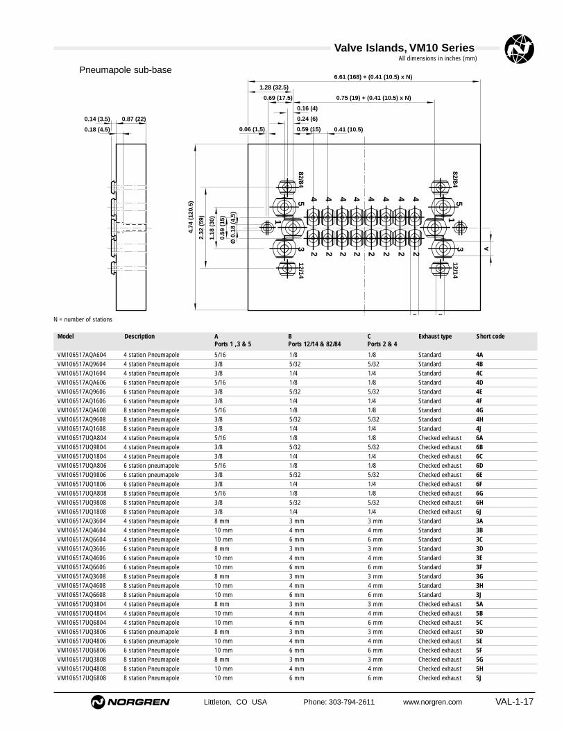
Littleton, CO USA Phone: 303-794-2611 www.norgren.com VAL-1-17
0.41 (10.5)
BC
0.18 (4.5)
0.87 (22)0.14 (3.5)
0.59 (15)0.06 (1,5)
0.24 (6)
0.16 (4)
0.75 (19) + (0.41 (10.5) x N)0.69 (17.5)
1.28 (32.5)
6.61 (168) + (0.41 (10.5) x N)
0.59
(15
)
Ø 0
.18
(4.5
)
1.18
(30
)
2.32
(59
)
A
4.74
(12
0.5)
32222
154444
2222
4444
12/14
12/14
82/84
82/843
1
5
VM106517AQA604 4 station Pneumapole 5/16 1/8 1/8 Standard 4AVM106517AQ9604 4 station Pneumapole 3/8 5/32 5/32 Standard 4BVM106517AQ1604 4 station Pneumapole 3/8 1/4 1/4 Standard 4CVM106517AQA606 6 station Pneumapole 5/16 1/8 1/8 Standard 4DVM106517AQ9606 6 station Pneumapole 3/8 5/32 5/32 Standard 4EVM106517AQ1606 6 station Pneumapole 3/8 1/4 1/4 Standard 4FVM106517AQA608 8 station Pneumapole 5/16 1/8 1/8 Standard 4GVM106517AQ9608 8 station Pneumapole 3/8 5/32 5/32 Standard 4HVM106517AQ1608 8 station Pneumapole 3/8 1/4 1/4 Standard 4JVM106517UQA804 4 station Pneumapole 5/16 1/8 1/8 Checked exhaust 6AVM106517UQ9804 4 station Pneumapole 3/8 5/32 5/32 Checked exhaust 6BVM106517UQ1804 4 station Pneumapole 3/8 1/4 1/4 Checked exhaust 6CVM106517UQA806 6 station pneumapole 5/16 1/8 1/8 Checked exhaust 6DVM106517UQ9806 6 station pneumapole 3/8 5/32 5/32 Checked exhaust 6EVM106517UQ1806 6 station Pneumapole 3/8 1/4 1/4 Checked exhaust 6FVM106517UQA808 8 station Pneumapole 5/16 1/8 1/8 Checked exhaust 6GVM106517UQ9808 8 station Pneumapole 3/8 5/32 5/32 Checked exhaust 6HVM106517UQ1808 8 station Pneumapole 3/8 1/4 1/4 Checked exhaust 6JVM106517AQ3604 4 station Pneumapole 8 mm 3 mm 3 mm Standard 3AVM106517AQ4604 4 station Pneumapole 10 mm 4 mm 4 mm Standard 3BVM106517AQ6604 4 station Pneumapole 10 mm 6 mm 6 mm Standard 3CVM106517AQ3606 6 station Pneumapole 8 mm 3 mm 3 mm Standard 3DVM106517AQ4606 6 station Pneumapole 10 mm 4 mm 4 mm Standard 3EVM106517AQ6606 6 station Pneumapole 10 mm 6 mm 6 mm Standard 3FVM106517AQ3608 8 station Pneumapole 8 mm 3 mm 3 mm Standard 3GVM106517AQ4608 8 station Pneumapole 10 mm 4 mm 4 mm Standard 3HVM106517AQ6608 8 station Pneumapole 10 mm 6 mm 6 mm Standard 3JVM106517UQ3804 4 station Pneumapole 8 mm 3 mm 3 mm Checked exhaust 5AVM106517UQ4804 4 station Pneumapole 10 mm 4 mm 4 mm Checked exhaust 5BVM106517UQ6804 4 station Pneumapole 10 mm 6 mm 6 mm Checked exhaust 5CVM106517UQ3806 6 station pneumapole 8 mm 3 mm 3 mm Checked exhaust 5DVM106517UQ4806 6 station pneumapole 10 mm 4 mm 4 mm Checked exhaust 5EVM106517UQ6806 6 station Pneumapole 10 mm 6 mm 6 mm Checked exhaust 5FVM106517UQ3808 8 station Pneumapole 8 mm 3 mm 3 mm Checked exhaust 5GVM106517UQ4808 8 station Pneumapole 10 mm 4 mm 4 mm Checked exhaust 5HVM106517UQ6808 8 station Pneumapole 10 mm 6 mm 6 mm Checked exhaust 5J
Pneumapole sub-base
Model Description Exhaust type Short codeA BPorts 1 ,3 & 5 Ports 12/14 & 82/84
CPorts 2 & 4
N = number of stations
All dimensions in inches (mm)

Valve Islands, VM10 Series
VAL-1-18 Littleton, CO USA Phone: 303-794-2611 www.norgren.com
A lbs (kg)ModelV11569-E01 3' (1 m) L1 0.61 (0.276)V11569-E03 10' (3 m) L2 1.49 (0.676)V11569-E05 16' (5 m) L3 2.37 (1.076)
PIN No. Wire colour Socket Station PIN No. Wire colour Socket Station1 White Solenoid 1–a 12 Brown Solenoid 2–a 23 Green Solenoid 3–a 34 Yellow Solenoid 4–a 45 Grey Solenoid 5–a 56 Pink Solenoid 6–a 67 Blue Solenoid 7–a 78 Red Solenoid 8–a 89 Black Solenoid 9–a 910 Violet Solenoid 10–a 1011 Grey Solenoid 11–a 1112 Red/Blue Solenoid 12–a 1213 White/Green Common-Ve –14 Brown/Green Solenoid 1–b 115 White/Yellow Solenoid 2–b 216 Yellow/Brown Solenoid 3–b 317 White/Grey Solenoid 4–b 418 Grey/Brown Solenoid 5–b 519 White/Pink Solenoid 6–b 620 Pink/Brown Solenoid 7–b 721 White/Blue Solenoid 8–b 822 Brown/Blue Solenoid 9–b 923 White/Red Solenoid 10–b 1024 Brown/Red Solenoid 11–b 1125 White/Black Solenoid 12–b 12
25 pin D sub-connector
114
1325
A
4"
.2
V11570-E01 3' (1 m) M1 0.62 (0.280)V11570-E03 10' (3 m) M2 1.50 (0.680)V11570-E05 16' (5 m) M3 2.38 (1.080)
44 pin D Sub-connector
11631
1530
44
A
4"
.2
1 White Solenoid 1–a 12 Brown Solenoid 2–a 23 Green Solenoid 3–a 34 Yellow Solenoid 4–a 45 Grey Solenoid 5–a 56 Pink Solenoid 6–a 67 Blue Solenoid 7–a 78 Red Solenoid 8–a 89 Black Solenoid 9–a 910 Violet Solenoid 10–a 1011 Grey Solenoid 11–a 1112 Red/Blue Solenoid 12–a 1213 White/Green Solenoid 13–a 1314 Brown/Green Solenoid 14–a 1415 White/Yellow Solenoid 15–a 1516 Yellow/Brown Solenoid 1–b 117 White/Grey Solenoid 2–b 218 Grey/Brown Solenoid 3–b 319 White/Pink Solenoid 4–b 420 Pink/Brown Solenoid 5–b 521 White/Blue Solenoid 6–b 622 Brown/Blue Solenoid 7–b 723 White/Red Solenoid 8–b 824 Brown/Red Solenoid 9–b 925 White/Black Solenoid 10–b 1026 Brown/Black Solenoid 11–b 1127 Grey/Green Solenoid 12–b 1228 Yellow/Grey Solenoid 13–b 1329 Pink/Green Solenoid 14–b 1430 Yellow/Pink Solenoid 15–b 1531 Green/Blue Solenoid 16–a 1632 Yellow/Blue Solenoid 16–b 1633 Green/Red NOT USED –34 Yellow/Red NOT USED –35 Green/Black NOT USED –36 Yellow/Black NOT USED –37 Grey/Blue NOT USED –38 Pink/Blue NOT USED –39 Grey/Red NOT USED –40 Pink/Red NOT USED –41 Grey/Black NOT USED –42 Pink/Black NOT USED –43 Blue/Black NOT USED –44 Red/Black Common -Ve –
Pressure switch
0.67 (17)
A
1.24 (31.5)
Note: Conforms to DIN 47100
p
3
1
AMP E–terminals 2.8 x 0.8Degree of protection: NEMA 1, IP00Non adjustablePressure range: 0 to 145 psig (0 to 10 bar)
Short code
A lbs (kg)Model Short code
A lbs (kg)Model Short code
VM106517AQ0804 0.16 (4) 7A 0.009 (0.004)VM106517AQ0806 0.24 (6) 7B 0.009 (0.004)
Valve Islands, VM10 Series
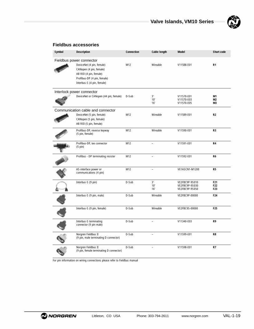
Littleton, CO USA Phone: 303-794-2611 www.norgren.com VAL-1-19
DeviceNet (4 pin, female)CANopen (4 pin, female)AB RIO (4 pin, female)Profibus-DP (4 pin, female)Interbus-S (4 pin, female)
DeviceNet or CANopen (44 pin, female)
DeviceNet (5 pin, female)CANopen (5 pin, female)AB RIO (5 pin, female)
Profibus-DP, reverse keyway (5 pin, female)
Profibus-DP, tee connector (5 pin)
Profibus - DP terminating resister
AS-interface power orcommunications (4 pin)
Interbus-S (9 pin)
Interbus-S (9 pin, male)
M12
D-Sub
M12
M12
M12
M12
M12
D-Sub
D-Sub
Wireable
3'10'16'
Wireable
Wireable
–
–
–
3'10'16'
Wireable
V11588-E01 R1
Fieldbus accessories
V11570-E01V11570-E03V11570-E05
M1M2M3
V11589-E01
V11590-E01
V11591-E01
V11592-E01
VE1ASCN1-M1200
VE2FBC9P-9S010VE2FBC9P-9S030VE2FBC9P-9S050
VE2FBC9P-00000
R2
R3
R4
R6
R5
F21F22F23
F24
Interbus-S (9 pin, female) D-Sub
D-Sub
Wireable VE2FBC9S-00000
V11340-E03
F25
R9
Norgren Fieldbus II(9 pin, male terminating D connector)
Interbus-S terminatingconnector (9 pin male)
D-Sub –
–
V11599-E01 R8
Norgren Fieldbus II(9 pin, female terminating D connector)
D-Sub – V11598-E01 R7
For pin information on wiring connections please refer to Fieldbus manual
Symbol
Fieldbus power connector
Communication cable and connector
Description Connection Cable length Model Short code
Interlock power connector

Valve Islands, VM10 Series
VAL-1-20 Littleton, CO USA Phone: 303-794-2611 www.norgren.com
VM103A11AB213B 2 x 3/2 - 2 x NC - Internal feed valve 3 mm PIF Turn & lock AA
VM103A11AB313B 2 x 3/2 - 2 x NC - Internal feed valve 3 mm PIF Push only AB
VM104A11AB213B 2 x 3/2 - 2 x NC - Internal feed valve 4 mm PIF Turn & lock AC
VM104A11AB313B 2 x 3/2 - 2 x NC - Internal feed valve 4 mm PIF Push only AD
VM106A11AB213B 2 x 3/2 - 2 x NC - Internal feed valve 6 mm PIF Turn & lock AE
VM106A11AB313B 2 x 3/2 - 2 x NC - Internal feed valve 6 mm PIF Push only AF
VM107A11AB213B 2 x 3/2 - 2 x NC - Internal feed valve no PIF Turn & lock AG
VM107A11AB313B 2 x 3/2 - 2 x NC - Internal feed valve no PIF Push only AH
VM103A22AB213B 2 x 3/2 - 2 x NC - External feed valve 3 mm PIF Turn & lock DA
VM103A22AB313B 2 x 3/2 - 2 x NC - External feed valve 3 mm PIF Push only DB
VM104A22AB213B 2 x 3/2 - 2 x NC - External feed valve 4 mm PIF Turn & lock DC
VM104A22AB313B 2 x 3/2 - 2 x NC - External feed valve 4 mm PIF Push only DD
VM106A22AB213B 2 x 3/2 - 2 x NC - External feed valve 6 mm PIF Turn & lock DE
VM106A22AB313B 2 x 3/2 - 2 x NC - External feed valve 6 mm PIF Push only DF
VM107A22AB213B 2 x 3/2 - 2 x NC - External feed valve no PIF Turn & lock DG
VM107A22AB313B 2 x 3/2 - 2 x NC - External feed valve no PIF Push only DH
VM10AA11AB213B 2 x 3/2 - 2 x NC - Internal feed valve 1/8" PIF Turn & lock AJ
VM10AA11AB313B 2 x 3/2 - 2 x NC - Internal feed valve 1/8" PIF Push only AK
VM109A11AB213B 2 x 3/2 - 2 x NC - Internal feed valve 5/32" PIF Turn & lock AL
VM109A11AB313B 2 x 3/2 - 2 x NC - Internal feed valve 5/32" PIF Push only AM
VM101A11AB213B 2 x 3/2 - 2 x NC - Internal feed valve 1/4" PIF Turn & lock AN
VM101A11AB313B 2 x 3/2 - 2 x NC - Internal feed valve 1/4" PIF Push only AP
VM10AA22AB213B 2 x 3/2 - 2 x NC - External feed valve 1/8" PIF Turn & lock DJ
VM10AA22AB313B 2 x 3/2 - 2 x NC - External feed valve 1/8" PIF Push only DK
VM109A22AB213B 2 x 3/2 - 2 x NC - External feed valve 5/32" PIF Turn & lock DL
VM109A22AB313B 2 x 3/2 - 2 x NC - External feed valve 5/32" PIF Push only DM
VM101A22AB213B 2 x 3/2 - 2 x NC - External feed valve 1/4" PIF Turn & lock DN
VM101A22AB313B 2 x 3/2 - 2 x NC - External feed valve 1/4" PIF Push only DP
VM103B11AB213B 2 x 3/2 - 2 x NO - Internal feed valve 3 mm PIF Turn & lock BA
VM103B11AB313B 2 x 3/2 - 2 x NO - Internal feed valve 3 mm PIF Push only BB
VM104B11AB213B 2 x 3/2 - 2 x NO - Internal feed valve 4 mm PIF Turn & lock BC
VM104B11AB313B 2 x 3/2 - 2 x NO - Internal feed valve 4 mm PIF Push only BD
VM106B11AB213B 2 x 3/2 - 2 x NO - Internal feed valve 6 mm PIF Turn & lock BE
VM106B11AB313B 2 x 3/2 - 2 x NO - Internal feed valve 6 mm PIF Push only BF
VM107B11AB213B 2 x 3/2 - 2 x NO - Internal feed valve no PIF Turn & lock BG
VM107B11AB313B 2 x 3/2 - 2 x NO - Internal feed valve no PIF Push only BH
VM103B22AB213B 2 x 3/2 - 2 x NO - External feed valve 3 mm PIF Turn & lock EA
VM103B22AB313B 2 x 3/2 - 2 x NO - External feed valve 3 mm PIF Push only EB
VM104B22AB213B 2 x 3/2 - 2 x NO - External feed valve 4 mm PIF Turn & lock EC
VM104B22AB313B 2 x 3/2 - 2 x NO - External feed valve 4 mm PIF Push only ED
VM106B22AB213B 2 x 3/2 - 2 x NO - External feed valve 6 mm PIF Turn & lock EE
VM106B22AB313B 2 x 3/2 - 2 x NO - External feed valve 6 mm PIF Push only EF
VM107B22AB213B 2 x 3/2 - 2 x NO - External feed valve no PIF Turn & lock EG
VM107B22AB313B 2 x 3/2 - 2 x NO - External feed valve no PIF Push only EH
VM10AB11AB213B 2 x 3/2 - 2 x NO - Internal feed valve 1/8" PIF Turn & lock BJ
VM10AB11AB313B 2 x 3/2 - 2 x NO - Internal feed valve 1/8" PIF Push only BK
VM109B11AB213B 2 x 3/2 - 2 x NO - Internal feed valve 5/32" PIF Turn & lock BL
VM109B11AB313B 2 x 3/2 - 2 x NO - Internal feed valve 5/32" PIF Push only BM
VM101B11AB213B 2 x 3/2 - 2 x NO - Internal feed valve 1/4" PIF Turn & lock BN
VM101B11AB313B 2 x 3/2 - 2 x NO - Internal feed valve 1/4" PIF Push only BP
VM10AB22AB213B 2 x 3/2 - 2 x NO - External feed valve 1/8" PIF Turn & lock EJ
VM10AB22AB313B 2 x 3/2 - 2 x NO - External feed valve 1/8" PIF Push only EK
VM109B22AB313B 2 x 3/2 - 2 x NO - External feed valve 5/32" PIF Push only EM
VM109B22AB213B 2 x 3/2 - 2 x NO - External feed valve 5/32" PIF Turn & lock EL
VM101B22AB213B 2 x 3/2 - 2 x NO - External feed valve 1/4" PIF Turn & lock EN
VM101B22AB313B 2 x 3/2 - 2 x NO - External feed valve 1/4" PIF Push only EP
Short codes for valve island specificationModel Description Short codeManual override

Valve Islands, VM10 Series
Littleton, CO USA Phone: 303-794-2611 www.norgren.com VAL-1-21
Short codes for valve island specification
VM103C11AB213B 2 x 3/2 - 1 x NC + 1 x NO - Internal feed valve 3 mm PIF Turn & lock CA
VM103C11AB313B 2 x 3/2 - 1 x NC + 1 x NO - Internal feed valve 3 mm PIF Push only CB
VM104C11AB213B 2 x 3/2 - 1 x NC + 1 x NO - Internal feed valve 4 mm PIF Turn & lock CC
VM104C11AB313B 2 x 3/2 - 1 x NC + 1 x NO - Internal feed valve 4 mm PIF Push only CD
VM106C11AB213B 2 x 3/2 - 1 x NC + 1 x NO - Internal feed valve 6 mm PIF Turn & lock CE
VM106C11AB313B 2 x 3/2 - 1 x NC + 1 x NO - Internal feed valve 6 mm PIF Push only CF
VM107C11AB213B 2 x 3/2 - 1 x NC + 1 x NO - Internal feed valve no PIF Turn & lock CG
VM107C11AB313B 2 x 3/2 - 1 x NC + 1 x NO - Internal feed valve no PIF Push only CH
VM103C22AB213B 2 x 3/2 - 1 x NC + 1 x NO - External feed valve 3 mm PIF Turn & lock FA
VM103C22AB313B 2 x 3/2 - 1 x NC + 1 x NO - External feed valve 3 mm PIF Push only FB
VM104C22AB213B 2 x 3/2 - 1 x NC + 1 x NO - External feed valve 4 mm PIF Turn & lock FC
VM104C22AB313B 2 x 3/2 - 1 x NC + 1 x NO - External feed valve 4 mm PIF Push only FD
VM106C22AB213B 2 x 3/2 - 1 x NC + 1 x NO - External feed valve 6 mm PIF Turn & lock FE
VM106C22AB313B 2 x 3/2 - 1 x NC + 1 x NO - External feed valve 6 mm PIF Push only FF
VM107C22AB213B 2 x 3/2 - 1 x NC + 1 x NO - External feed valve no PIF Turn & lock FG
VM107C22AB313B 2 x 3/2 - 1 x NC + 1 x NO - External feed valve no PIF Push only FH
VM10AC11AB213B 2 X 3/2 - 1 X N/C + 1 X N/O - Internal feed valve 1/8" PIF Turn & lock CJ
VM10AC11AB313B 2 X 3/2 - 1 X N/C + 1 X N/O - Internal feed valve 1/8" PIF Push only CK
VM109C11AB213B 2 X 3/2 - 1 X N/C + 1 X N/O - Internal feed valve 5/32" PIF Turn & lock CL
VM109C11AB313B 2 X 3/2 - 1 X N/C + 1 X N/O - Internal feed valve 5/32" PIF Push only CM
VM101C11AB213B 2 X 3/2 - 1 X N/C + 1 X N/O - Internal feed valve 1/4" PIF Turn & lock CN
VM101C11AB313B 2 X 3/2 - 1 X N/C + 1 X N/O - Internal feed valve 1/4" PIF Push only CP
VM10AC22AB213B 2 X 3/2 - 1 X N/C + 1 X N/O - External feed valve 1/8" PIF Turn & lock FJ
VM10AC22AB313B 2 X 3/2 - 1 X N/C + 1 X N/O - External feed valve 1/8" PIF Push only FK
VM109C22AB213B 2 X 3/2 - 1 X N/C + 1 X N/O - External feed valve 5/32" PIF Turn & lock FL
VM109C22AB313B 2 X 3/2 - 1 X N/C + 1 X N/O - External feed valve 5/32" PIF Push only FM
VM101C22AB213B 2 X 3/2 - 1 X N/C + 1 X N/O - External feed valve 1/4" PIF Turn & lock FN
VM101C22AB313B 2 X 3/2 - 1 X N/C + 1 X N/O - External feed valve 1/4" PIF Push only FP
VM103517AB213B 5/2 Solenoid Spring - Internal feed valve 3mm PIF Turn & lock GA
VM103517AB313B 5/2 Solenoid Spring - Internal feed valve 3mm PIF Push only GB
VM104517AB213B 5/2 Solenoid Spring - Internal feed valve 4mm PIF Turn & lock GC
VM104517AB313B 5/2 Solenoid Spring - Internal feed valve 4mm PIF Push only GD
VM106517AB213B 5/2 Solenoid Spring - Internal feed valve 6mm PIF Turn & lock GE
VM106517AB313B 5/2 Solenoid Spring - Internal feed valve 6mm PIF Push only GF
VM107517AB213B 5/2 Solenoid Spring - Internal feed valve No PIF Turn & lock GG
VM107517AB313B 5/2 Solenoid Spring - Internal feed valve No PIF Push only GH
VM103527AB213B 5/2 Solenoid Spring - External feed valve 3mm PIF Turn & lock HA
VM103527AB313B 5/2 Solenoid Spring - External feed valve 3mm PIF Push only HB
VM104527AB213B 5/2 Solenoid Spring - External feed valve 4mm PIF Turn & lock HC
VM104527AB313B 5/2 Solenoid Spring - External feed valve 4mm PIF Push only HD
VM106527AB213B 5/2 Solenoid Spring - External feed valve 6mm PIF Turn & lock HE
VM106527AB313B 5/2 Solenoid Spring - External feed valve 6mm PIF Push only HF
VM107527AB213B 5/2 Solenoid Spring - External feed valve No PIF Turn & lock HG
VM107527AB313B 5/2 Solenoid Spring - External feed valve No PIF Push only HH
VM10A517AB213B 5/2 Solenoid Spring - Internal feed valve 1/8" PIF Turn & lock GJ
VM10A517AB313B 5/2 Solenoid Spring - Internal feed valve 1/8" PIF Push only GK
VM109517AB213B 5/2 Solenoid Spring - Internal feed valve 5/32" PIF Turn & lock GL
VM109517AB313B 5/2 Solenoid Spring - Internal feed valve 5/32" PIF Push only GM
VM101517AB213B 5/2 Solenoid Spring - Internal feed valve 1/4" PIF Turn & lock GN
VM101517AB313B 5/2 Solenoid Spring - Internal feed valve 1/4" PIF Push only GP
VM10A527AB213B 5/2 Solenoid Spring - External feed valve 1/8" PIF Turn & lock HJ
VM10A527AB313B 5/2 Solenoid Spring - External feed valve 1/8" PIF Push only HK
VM109527AB213B 5/2 Solenoid Spring - External feed valve 5/32" PIF Turn & lock HL
VM109527AB313B 5/2 Solenoid Spring - External feed valve 5/32" PIF Push only HM
VM101527AB213B 5/2 Solenoid Spring - External feed valve 1/4" PIF Turn & lock HN
VM101527AB313B 5/2 Solenoid Spring - External feed valve 1/4" PIF Push only HP
Model Description Short codeManual override

Valve Islands, VM10 Series
VAL-1-22 Littleton, CO USA Phone: 303-794-2611 www.norgren.com
VM103511AB213B 5/2 Solenoid Solenoid - Internal feed valve 3 mm PIF Turn & lock JA
VM103511AB313B 5/2 Solenoid Solenoid - Internal feed valve 3 mm PIF Push only JB
VM104511AB213B 5/2 Solenoid Solenoid - Internal feed valve 4 mm PIF Turn & lock JC
VM104511AB313B 5/2 Solenoid Solenoid - Internal feed valve 4 mm PIF Push only JD
VM106511AB213B 5/2 Solenoid Solenoid - Internal feed valve 6 mm PIF Turn & lock JE
VM106511AB313B 5/2 Solenoid Solenoid - Internal feed valve 6 mm PIF Push only JF
VM107511AB213B 5/2 Solenoid Solenoid - Internal feed valve No PIF Turn & lock JG
VM107511AB313B 5/2 Solenoid Solenoid - Internal feed valve No PIF Push only JH
VM103522AB213B 5/2 Solenoid Solenoid - External feed valve 3 mm PIF Turn & lock KA
VM103522AB313B 5/2 Solenoid Solenoid - External feed valve 3 mm PIF Push only KB
VM104522AB213B 5/2 Solenoid Solenoid - External feed valve 4 mm PIF Turn & lock KC
VM104522AB313B 5/2 Solenoid Solenoid - External feed valve 4 mm PIF Push only KD
VM106522AB213B 5/2 Solenoid Solenoid - External feed valve 6 mm PIF Turn & lock KE
VM106522AB313B 5/2 Solenoid Solenoid - External feed valve 6 mm PIF Push only KF
VM107522AB213B 5/2 Solenoid Solenoid - External feed valve No PIF Turn & lock KG
VM107522AB313B 5/2 Solenoid Solenoid - External feed valve No PIF Push only KH
VM10A511AB213B 5/2 Solenoid Solenoid - Internal feed valve 1/8" PIF Turn & lock JJ
VM10A511AB313B 5/2 Solenoid Solenoid - Internal feed valve 1/8" PIF Push only JK
VM109511AB213B 5/2 Solenoid Solenoid - Internal feed valve 5/32" PIF Turn & lock JL
VM109511AB313B 5/2 Solenoid Solenoid - Internal feed valve 5/32" PIF Push only JM
VM101511AB213B 5/2 Solenoid Solenoid - Internal feed valve 1/4" PIF Turn & lock JN
VM101511AB313B 5/2 Solenoid Solenoid - Internal feed valve 1/4" PIF Push only JP
VM10A522AB213B 5/2 Solenoid Solenoid - External feed valve 1/8" PIF Turn & lock KJ
VM10A522AB313B 5/2 Solenoid Solenoid - External feed valve 1/8" PIF Push only KK
VM109522AB213B 5/2 Solenoid Solenoid - External feed valve 5/32" PIF Turn & lock KL
VM109522AB313B 5/2 Solenoid Solenoid - External feed valve 5/32" PIF Push only KM
VM101522AB213B 5/2 Solenoid Solenoid - External feed valve 1/4" PIF Turn & lock KN
VM101522AB313B 5/2 Solenoid Solenoid - External feed valve 1/4" PIF Push only KP
VM103611AB213B 5/3 APB Solenoid Solenoid - Internal feed valve 3 mm PIF Turn & lock LA
VM103611AB313B 5/3 APB Solenoid Solenoid - Internal feed valve 3 mm PIF Push only LB
VM104611AB213B 5/3 APB Solenoid Solenoid - Internal feed valve 4 mm PIF Turn & lock LC
VM104611AB313B 5/3 APB Solenoid Solenoid - Internal feed valve 4 mm PIF Push only LD
VM106611AB213B 5/3 APB Solenoid Solenoid - Internal feed valve 6 mm PIF Turn & lock LE
VM106611AB313B 5/3 APB Solenoid Solenoid - Internal feed valve 6 mm PIF Push only LF
VM107611AB213B 5/3 APB Solenoid Solenoid - Internal feed valve No PIF Turn & lock LG
VM107611AB313B 5/3 APB Solenoid Solenoid - Internal feed valve No PIF Push only LH
VM103622AB213B 5/3 APB Solenoid Solenoid - External feed valve 3 mm PIF Turn & lock MA
VM103622AB313B 5/3 APB Solenoid Solenoid - External feed valve 3 mm PIF Push only MB
VM104622AB213B 5/3 APB Solenoid Solenoid - External feed valve 4 mm PIF Turn & lock MC
VM104622AB313B 5/3 APB Solenoid Solenoid - External feed valve 4 mm PIF Push only MD
VM106622AB213B 5/3 APB Solenoid Solenoid - External feed valve 6 mm PIF Turn & lock ME
VM106622AB313B 5/3 APB Solenoid Solenoid - External feed valve 6 mm PIF Push only MF
VM107622AB213B 5/3 APB Solenoid Solenoid - External feed valve No PIF Turn & lock MG
VM107622AB313B 5/3 APB Solenoid Solenoid - External feed valve No PIF Push only MH
VM10A611AB213B 5/3 APB Solenoid Solenoid - Internal feed valve 1/8" PIF Turn & lock LJ
VM10A611AB313B 5/3 APB Solenoid Solenoid - Internal feed valve 1/8" PIF Push only LK
VM109611AB213B 5/3 APB Solenoid Solenoid - Internal feed valve 5/32" PIF Turn & lock LL
VM109611AB313B 5/3 APB Solenoid Solenoid - Internal feed valve 5/32" PIF Push only LM
VM101611AB213B 5/3 APB Solenoid Solenoid - Internal feed valve 1/4" PIF Turn & lock LN
VM101611AB313B 5/3 APB Solenoid Solenoid - Internal feed valve 1/4" PIF Push only LP
VM10A622AB213B 5/3 APB Solenoid Solenoid - External feed valve 1/8" PIF Turn & lock MJ
VM10A622AB313B 5/3 APB Solenoid Solenoid - External feed valve 1/8" PIF Push only MK
VM109622AB213B 5/3 APB Solenoid Solenoid - External feed valve 5/32" PIF Turn & lock ML
VM109622AB313B 5/3 APB Solenoid Solenoid - External feed valve 5/32" PIF Push only MM
VM101622AB213B 5/3 APB Solenoid Solenoid - External feed valve 1/4" PIF Turn & lock MN
VM101622AB313B 5/3 APB Solenoid Solenoid - External feed valve 1/4" PIF Push only MP
Model Description Manual override Short code
Short codes for valve island specification

Valve Islands, VM10 Series
Littleton, CO USA Phone: 303-794-2611 www.norgren.com VAL-1-23
VM107A11UB213B 2 x 3/2 - 2 x NC - Internal feed valve No PIF Turn & lock NA
VM107A11UB313B 2 x 3/2 - 2 x NC - Internal feed valve No PIF Push only NB
VM107A22UB213B 2 x 3/2 - 2 x NC - External feed valve No PIF Turn & lock RA
VM107A22UB313B 2 x 3/2 - 2 x NC - External feed valve No PIF Push only RB
VM107B11UB213B 2 x 3/2 - 2 x NO - Internal feed valve No PIF Turn & lock PA
VM107B11UB313B 2 x 3/2 - 2 x NO - Internal feed valve No PIF Push only PB
VM107B22UB213B 2 x 3/2 - 2 x NO - External feed valve No PIF Turn & lock SA
VM107B22UB313B 2 x 3/2 - 2 x NO - External feed valve No PIF Push only SB
VM107C11UB213B 2 x 3/2 - 1 x NC + 1 x NO - Internal feed valve No PIF Turn & lock QA
VM107C11UB313B 2 x 3/2 - 1 x NC + 1 x NO - Internal feed valve No PIF Push only QB
VM107C22UB213B 2 x 3/2 - 1 x NC + 1 x NO - External feed valve No PIF Turn & lock TA
VM107C22UB313B 2 x 3/2 - 1 x NC + 1 x NO - External feed valve No PIF Push only TB
VM107517UB213B 5/2 Solenoid Spring - Internal feed valve No PIF Turn & lock UA
VM107517UB313B 5/2 Solenoid Spring - Internal feed valve No PIF Push only UB
VM107527UB213B 5/2 Solenoid Spring - External feed valve No PIF Turn & lock VA
VM107527UB313B 5/2 Solenoid Spring - External feed valve No PIF Push only VB
VM107511UB213B 5/2 Solenoid Solenoid - Internal feed valve No PIF Turn & lock WA
VM107511UB313B 5/2 Solenoid Solenoid - Internal feed valve No PIF Push only WB
VM107522UB213B 5/2 Solenoid Solenoid - External feed valve No PIF Turn & lock XA
VM107522UB313B 5/2 Solenoid Solenoid - External feed valve No PIF Push only XB
VM107611UB213B 5/3 APB Solenoid Solenoid - Internal feed valve No PIF Turn & lock YA
VM107611UB313B 5/3 APB Solenoid Solenoid - Internal feed valve No PIF Push only YB
VM107622UB213B 5/3 APB Solenoid Solenoid - External feed valve No PIF Turn & lock ZA
VM107622UB313B 5/3 APB Solenoid Solenoid - External feed valve No PIF Push only ZB
Model Description Manual override Short code
VM10 checked exhaust valve codes

VAL-1-24 Littleton, CO USA Phone: 303-794-2611 www.norgren.com
VM10 Valve Island Specification
Valve island specification form VIP/.........................................................
Using the short order codes provided complete the build model below.One valve island per sheet only Unit ID No. . . . . . . . . . . . . . . . . . . . . . .
Norgren to specifyNo. of units required
Company name . . . . . . . . . . . . . . . . . . . . . . . . . . . . . . . . . . . . . . Contact name . . . . . . . . . . . . . . . . . . . . . . . . . . . . . . . . . . .
Address . . . . . . . . . . . . . . . . . . . . . . . . . . . . . . . . . . . . . . . . . . . Tel no . . . . . . . . . . . . . . . . . . . . . . . . . . . . . . . . . . . . . . . . .
. . . . . . . . . . . . . . . . . . . . . . . . . . . . . . . . . . . . . . . . . . . . . . . . . . Fax no. . . . . . . . . . . . . . . . . . . . . . . . . . . . . . . . . . . . . . . . .
. . . . . . . . . . . . . . . . . . . . . . . . . . . . . . . . . . . . . . . . . . . . . . . . . . E-mail . . . . . . . . . . . . . . . . . . . . . . . . . . . . . . . . . . . . . . . . .
Valve range: VM10
End plate code
Valve codes
Accessories
Connection optionsSelect one only
Standard: 24 V d.c. negative common (Multipole & Fieldbus)
Multipole 24 V d.c. positive common
Short code Qty per island
Options - select one only
Individuallywired2 to 20 stations
CANopen8, 10, 12 & 16stations
CANopen withinterlocks 8, 10, 12 & 16stations
AB RIO8, 10, 12 & 16stations
AS interface4, 6 & 8 stations
Norgren FieldbusII4, 6, 8, 10, 12 &16 stations
25 pin IP65 D-sub connector4, 6, 8, 10 & 12stations
44 pin IP65 D-sub connector10, 12 & 16stations
Interbus-S 8, 10, 12 & 16stations
Profibus – DP8, 10, 12 & 16stations
DeviceNet8, 10, 12 &16 stations
DeviceNet withinterlocks 8,10, 12 & 16stations

Littleton, CO USA Phone: 303-794-2611 www.norgren.com VAL-1-25
Fieldbus Specification for VM10
Fieldbus system specification form VIE/ ..................................................
Company name . . . . . . . . . . . . . . . . . . . . . . . . . . . . . . . . . . . . . . Contact name . . . . . . . . . . . . . . . . . . . . . . . . . . . . . . . . . . .
Address . . . . . . . . . . . . . . . . . . . . . . . . . . . . . . . . . . . . . . . . . . . Tel no . . . . . . . . . . . . . . . . . . . . . . . . . . . . . . . . . . . . . . . . .
. . . . . . . . . . . . . . . . . . . . . . . . . . . . . . . . . . . . . . . . . . . . . . . . . . Fax no. . . . . . . . . . . . . . . . . . . . . . . . . . . . . . . . . . . . . . . . .
. . . . . . . . . . . . . . . . . . . . . . . . . . . . . . . . . . . . . . . . . . . . . . . . . . E-mail . . . . . . . . . . . . . . . . . . . . . . . . . . . . . . . . . . . . . . . . .
Using the short order codes provided complete the build model below.
One valve island per sheet only. . . . . . . . . . . . . . . . . . . . . . Unit ID No. . . . . . . . . . . . . . . . . . . . . . . . . . . . . . . . . . . . . . . . . . . . . . . . . . . . . . . . . . . . . . . . . . . . . . . . . . . . . . . . . . Norgren to specify
Distributed configuration, No. of units required
Remote inputs and outputs, No. of units required
Accessories
F5
Code
Distributed cables
Power cables (1 per node)
Sensor cables
Solenoid cable
Communication connectors
Code
No. of units
Quantity
LHSend plate
Outputmodule
Inputmodule
LHSend plate
Outputmodule
Inputmodule
Fieldbusnode
Sub-base
Outputmodule
Inputmodule
RHSendplate
RHSendplate

Littleton, CO USA Phone: 303-794-2611 www.norgren.com VAL-2-1
Section 2
ContentsFeatures and Technical Data .............................VAL-2-2Valve Islands, V20 Series ...................................VAL-2-7Valve Islands, V22 Series .................................VAL-2-15Fieldbus II, VE2 .................................................VAL-2-23Glossary ............................................................VAL-2-41
V20, V22 Valve Manifoldand Fieldbus II
V22 Series with Fieldbus

VAL-2-2 Littleton, CO USA Phone: 303-794-2611 www.norgren.com
Fieldbus
System products tailored to your businessNorgrens Fieldbus II products are designed with flexibility in mind. Our designallows for a centralized or distributed system to be built for the most efficient useof the 128 I/O available per node.
V20 and V22 Series System Valves are the ideal partners for Fieldbus II or canbe used independently as Valve Manifolds with a choice of Wireway connectors.
Depending on the protocol being used, Norgrens Fieldbus II provides immediatefeedback on failure of system components.
Fieldbus Diagnostics
Dedicated systemvalves
5/2, 5/3 and 2 x 3/2 functionsavailable in a single slice
IP65/NEMA 4protection rating
maintained with centralizedand distributed systems
Expandable I/OUp to 64 inputsand 64 outputs
from a single node
Rapid AssemblyI/O units simply clip togetherand are easily tailored to suit
individual needs
Alternativemounting
DIN Rail or surfacemountable
Optionalconnections
choose from NPT, ISO Gand push-in fittings
InterchangeableFieldbus node
available in allmajor protocols

Littleton, CO USA Phone: 303-794-2611 www.norgren.com VAL-2-3
Fieldbus
Its a family affair!V22 series Valves & Fieldbus IIA Centralized system proves to be a popularchoice with machine designers. It provides thefocus for control and with a protection rating ofNEMA 4/IP65 it need not be mounted inside acabinet.
V22 series valves provide Cv of 1.2 from astacking width of just 0.79 inches.
V20 series Valves & Fieldbus IILike the V22 series V20 can be directlycoupled to Fieldbus II to form an NEMA 4/IP65rated Centralized system. They can also beused in a Distributed system and up to 64solenoids can be linked to just one FieldbusNode.
V20 series valves provide Cv of 0.4 from astacking width of just 0.71 inches.
AS-InterfaceOur unique Integrated AS-I modules give youthe opportunity to directly connect either a V20or V22 series Valve Manifold to an AS-I system.Up to 8 solenoids can be driven on one ValveManifold.
WirewayChoose from 25 pin D sub connector or aNEMA 4 conduit type. Special cable assemblieswith a shrouded 25 pin D sub connector ensurea NEMA 4 protection rating.

VAL-2-4 Littleton, CO USA Phone: 303-794-2611 www.norgren.com
Fieldbus
Protocol DeviceNet Interbus ‘S’ Profibus-DP AS-Interface CANOpen
Number of outputs per module 64 64 64 4 64
Number of inputs per module 64 64 64 4 64
Bus topology Line Ring Line Tree/Line Line
System Configuration Multi Master Single Master Max 3 Masters Single Master Multi MasterMulti Slaves Multi Slaves Multi Slaves Multi Slaves Multi Slaves
Communication Interface CAN RS 422 RS 485 ASI CAN
Max Baud Rate 500 Kbits/sec 500 Kbits/sec 12 Mbits/sec N/A (max cycle 500 Kbits/sectime 16 ft (5m)
Cable length at max baud rate 328 ft (100m) 1312 ft (400m) 656 ft (200m) or Sec 328 ft (100m) 328 ft (100m)between nodes 8 3281 ft (1000m)mi (13 km) max with repeater
Number of units per 64 nodes 64 + master 3 masters + 121 31 + master 64 nodesinstallation slaves with
repeaters
Cable 4 wires 4 wires 2 wires 2 wires 4 wires+ screen + ground + screen + screen (data + power) + screen
24V5V
STATUS
RCRB
RDUS
5VI
incorporating
INTERBUS-S
24V5V
STATUS
RCRB
RDUS
5VI
incorporating
INTERBUS-S
Distributed System
We talk your language
128 I/O per NodeUp to 64 inputs and 64 outputs are available per Node. This allows for avery efficient layout exactly matching your machine design needs. NEMA4 rated plug and cable assemblies are available as part of our standardprogram.
Pneumatic EfficiencyLong pipe runs with intermediate fittings not only reduce availablepressure, but also contribute to a reduction in flow. Being able to locateyour control valves close to their respective actuators ensures the mostefficient and responsive pneumatic circuit.

Littleton, CO USA Phone: 303-794-2611 www.norgren.com VAL-2-5
Fieldbus
V20 and V22 valves and Fieldbus II
Accessories
Connectability
Technical DataIndication by yellow LEDSuppression by flywheel diodeDiagnostic:
Yellow LED = correct movement of armatureFlashing yellow LED = failed operation50% power saving following correct armature movement
Temperature Range:-4° to 122°F (-20° to 50°C)*Consult our Technical Service for use below 35°F (2°C)
Degree of protection:NEMA 1 ‘D’ sub-connectorNEMA 4 ‘D’ sub-connector with shroudNEMA 4 conduit entry typeNEMA 4 AS-I with M12 connectors
Materials:Glass fiber reinforced polymer mouldings for solenoid and electrical housings. Conduit end caps – zinc pressure die-cast. Aluminum alloy end plates, bodies and sub-base modules.
25-Pin AS-I Fieldbus 1" Conduit Remote‘D’ Output
Cables Intermediate supply/exhaust plate Blanking plate
V22 (n x 0.79) + 3.43 [(n x 20) + 87]4.33 (110)(n x 1.77) + 0.98 [(n x 45) + 25]
Overall height: 3.39 (86)
V22
5.60
(142
)
V20
4.80
(122
)
V20 (n x 0.71 ) +1.73 [(n x 18) + 44]
5.83
(148
)
V22 (n x 0.79) + 3.43 [(n x 20) + 87]
Overall height: V22 - 3.31 (84) V20 - 2.76 (70)
V22
5.59
(142
)
V20
4.80
(122
)
V20 (n x 0.71) + 1.73 [(n x 18) + 44]n = number of stationsAll dimensions are in mm
All Dimensions in Inches (mm)
VAL-2-6 Littleton, CO USA Phone: 303-794-2611 www.norgren.com
Fieldbus
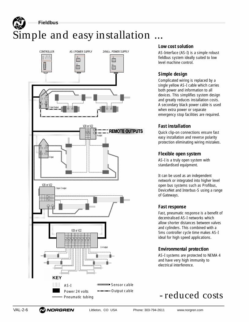
- reduced costs
Simple and easy installation ...Low cost solutionAS-Interface (AS-I) is a simple robustfieldbus system ideally suited to lowlevel machine control.
Simple designComplicated wiring is replaced by asingle yellow AS-I cable which carriesboth power and information to alldevices. This simplifies system designand greatly reduces installation costs.A secondary black power cable is usedwhen extra power or separate emergency stop facilities are required.
Fast installationQuick clip-on connections ensure fasteasy installation and reverse polarityprotection eliminating wiring mistakes.
Flexible open systemAS-I is a truly open system with standardised equipment.
It can be used as an independent network or integrated into higher levelopen bus systems such as Profibus,DeviceNet and Interbus-S using a rangeof Gateways.
Fast responseFast, pneumatic response is a benefit ofdecentralised AS-I networks whichallow shorter distances between valvesand cylinders. This combined with a5ms controller cycle time makes AS-Iideal for high speed applications.
Environmental protectionAS-I systems are protected to NEMA 4and have very high immunity to electrical interference.
AS-I
Power 24 volts Pneumatic tubing
Sensor cable
Output cable
CONTROLLER 24Vd.c. POWER SUPPLYAS-I POWER SUPPLY
2 input 2output
V20 or V22
4 input
2 x 4 output
2 input / 2 output
KEY
V20 or V22
4 output
V20 or V22

● Wireway design for easy installation
● NEMA 1 and NEMA 4 25-pin “D” sub-connectormodels
● NEMA 4 Conduit entry models
● Fieldbus compatible
● Dedicated AS-Interface modules
Technical Data ValvesMedium:
Compressed air, filtered, lubricated and non-lubricatedOperation:
Spool valve, indirectly actuatedSolenoid Voltage:
24 V d.c.Port Size (sub-base):
1/8" NPT or ISO G1/4" PIF
Operating Pressure:Maximum 116 psig (8 bar)
Flow Characteristics:Size Function Cv l/min1/8" NPT 5/2,3/2 0.46 4531/8" NPT 5/3 APB 0.28 274
Ambient Temperature:-4° to 122°F (-20° to 50°C) Solenoid models
*Consult our Technical Service for use below 35°F (2°C)
Materials:Body, sub-base, end plates pressure – die cast aluminumEnd covers – PPSSolenoids – glass reinforced acetal copolymer and PBT
Technical Data WirewayIndication by yellow LEDSuppression by flywheel diodeTemperature Range:
-4° to 122°F* (-20° to 50°C)*Consult our Technical Service for use below 35°F (2°C)
Degree of Protection:NEMA 1 ‘D’ sub-connectorNEMA 4 ‘D’ sub-connector with sealNEMA 4 conduit entry type
Valve Islands, V20 SeriesSub-base Mounted 2 x 3/2, 5/2 and 5/3
Valves Solenoid Actuated with Wireway
Littleton, CO USA Phone: 303-794-2611 www.norgren.com VAL-2-7

VAL-2-8 Littleton, CO USA Phone: 303-794-2611 www.norgren.com
Valve Islands, V20 Series
Symbol Model Manual Function Solenoid Actuation Operating Solenoid Pilot OrderOverride 2x3/2 Pilot Supply Pressure psi (bar) Pressure psi (bar) Code
V206A11A-B213R lockingNormally closed Internal Sol/spring
32 to 116–
01
V206A11A-B313R non-locking (2.2 to 8) 02
V206B11A-B213R lockingNormally open Internal Sol/Spring
32 to 116–
03
V206B11A-B313R non-locking (2.2 to 8) 04
V206A22A-B213R lockingNormally closed External Sol/Spring
26" Hg to 145 32 to 116 05
V206A22A-B313R non-locking (-0.9 to 10) (2.2 to 8) 06
V206B22A-B213R lockingNormally open External Sol/Spring
26" Hg to 145 32 to 116 07
V206B22A-B313R non-locking (-0.9 to 10) (2.2 to 8) 08
V206C11A-B213R locking Normally open/ Internal Sol/Spring32 to 116
–09
V206C11A-B313R non-locking normally closed (2.2 to 8) 10
V206C22A-B213R locking Normally open/ External Sol/Spring26" Hg to 145 32 to 116 11
V206C22A-B313R non-locking normally closed (-0.9 to 10) (2.2 to 8) 12
APB = All Ports Blocked COE = Center Open ExhaustCOP = Center Open Pressure
General Information2x3/2 Solenoid Actuated Valves
3 1 5
2 4
10 1012 14
3 1 5
2 4
12 1410 10
3 1 5
2 4
10 101412
3 1 5
2 4
12 1410 10
3 1 5
2 4
12 1010 14
3 1 5
2 4
12 1010 14
Symbol Model Manual Solenoid Mid Position Operating Solenoid Pilot OrderOverride Pilot Supply Pressure psi (bar) Pressure psi (bar) Code
V206517A-B213R lockingInternal Sol/Spring
26 to 116–
13
V206517A-B313R non-locking (1.8 to 8) 14
V206527A-B213R lockingExternal Sol/Spring
26" Hg to 145 26 to 116 15
V206527A-B313R non-locking (-0.9 to 10) (1.8 to 8) 16
V206516A-B213R lockingInternal Sol/Air
22 to 116–
17
V206516A-B313R non-locking (1.5 to 8) 18
V206526A-B213R lockingExternal Sol/Air
26" Hg to 145 22 to 116 19
V206526A-B313R non-locking (-0.9 to 10) (1.5 to 8) 20
V206511A-B213R lockingInternal Sol/Sol
17 to 116–
21
V206511A-B313R non-locking (1.2 to 8) 22
V206522A-B213R lockingExternal Sol/Sol
26" Hg to 145 17 to 116 23
V206522A-B313R non-locking (-0.9 to 10) (1.2 to 8) 24
5/2 Solenoid Actuated Valves
4 2
1214
5 1 3
4 2
12
14 5 1 3
4 2
12
14 5 1 3
4 2
12
14 5 1 3
4 214
5 1 3
12
4 2
5 1 3
12
14 12
Symbol Model Manual Solenoid Mid Position Operating Solenoid Pilot OrderOverride Pilot Supply Pressure psi (bar) Pressure psi (bar) Code
V206611A-B213R lockingInternal APB
32 to 116–
25
V206611A-B313R non-locking (2.2 to 8) 26
V206622A-B213R lockingExternal APB
26" Hg to 145 32 to 116 27
V206622A-B313R non-locking (-0.9 to 10) (2.2 to 8) 28
V206711A-B213R lockingInternal COE
32 to 116–
29
V206711A-B313R non-locking (2.2 to 8) 30
V206722A-B213R lockingExternal COE
26" Hg to 145 32 to 116 31
V206722A-B313R non-locking (-0.9 to 10) (2.2 to 8) 32
V206811A-B213R lockingInternal COP
32 to 116–
33
V206811A-B313R non-locking (2.2 to 8) 34
V206822A-B213R lockingExternal COP
26" Hg to 145 32 to 116 35
V206822A-B313R non-locking (-0.9 to 10) (2.2 to 8) 36
5/3 Double Solenoid Actuated Valves
4
5 1 3
214 12
4
5 1 3
2
12/14
1214
4
5 1 3
214 12
4
5 1 3
2
12/14
14 12
4 2 1214
5 1 3
4
5 1 3
2
12/14
1214
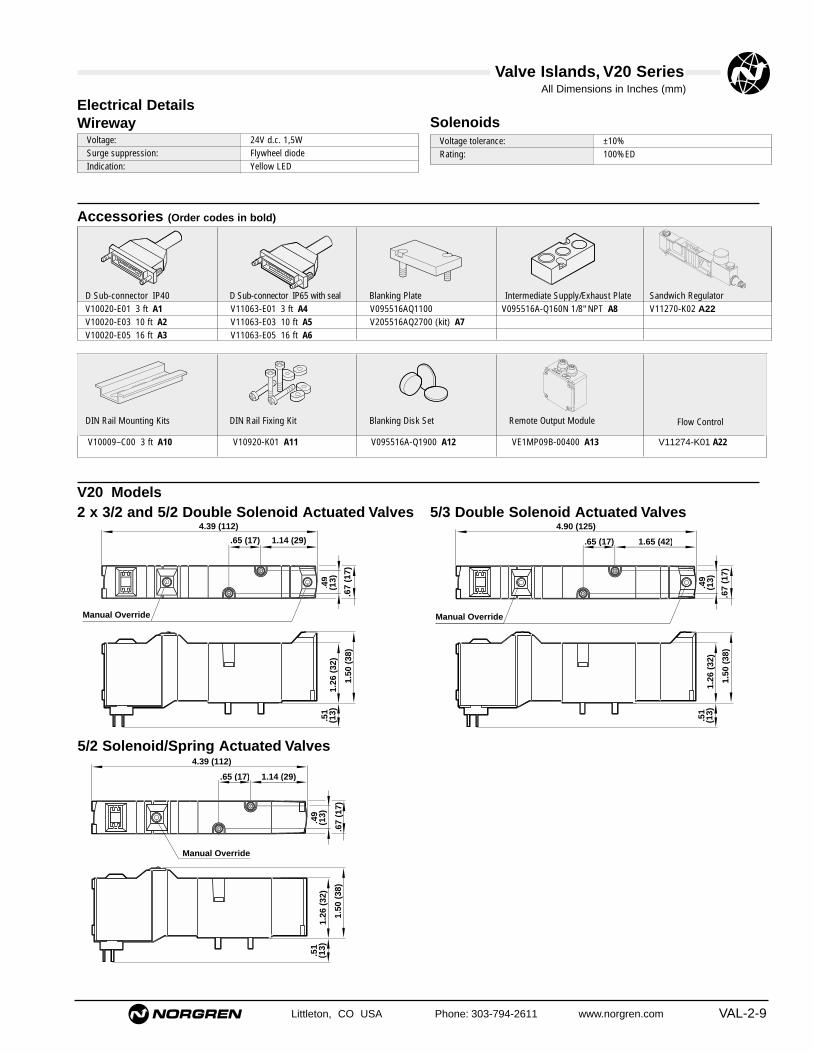
Flow Control
V10020-E01 3 ft A1 V11063-E01 3 ft A4 V095516AQ1100 V095516A-Q160N 1/8" NPT A8 V11270-K02 A22V10020-E03 10 ft A2 V11063-E03 10 ft A5 V205516AQ2700 (kit) A7V10020-E05 16 ft A3 V11063-E05 16 ft A6
Valve Islands, V20 Series All Dimensions in Inches (mm)
Littleton, CO USA Phone: 303-794-2611 www.norgren.com VAL-2-9
SolenoidsWirewayElectrical Details
Accessories (Order codes in bold)
D Sub-connector IP40 D Sub-connector IP65 with seal Blanking Plate Intermediate Supply/Exhaust Plate Sandwich Regulator
DIN Rail Mounting Kits DIN Rail Fixing Kit Blanking Disk Set Remote Output Module
V20 Models5/3 Double Solenoid Actuated Valves
1.65 (42).65 (17)
4.90 (125)
.49
(13)
.67
(17)
1.26
(32
).5
1(1
3)
1.50
(38
)
Manual Override
2 x 3/2 and 5/2 Double Solenoid Actuated Valves
1.14 (29).65 (17)
4.39 (112)
.49
(13)
.67
(17)
1.26
(32
).5
1(1
3)
1.50
(38
)
Manual Override
5/2 Solenoid/Spring Actuated Valves
1.14 (29).65 (17)
4.39 (112)
.49
(13)
.67
(17)
1.26
(32
).5
1(1
3)
1.50
(38
)
Manual Override
Voltage tolerance: ±10%Rating: 100%ED
Voltage: 24V d.c. 1,5WSurge suppression: Flywheel diodeIndication: Yellow LED
V10009–C00 3 ft A10 V10920-K01 A11 V095516A-Q1900 A12 VE1MP09B-00400 A13 V11274-K01 A22

Valve Islands, V20 Series All Dimensions in Inches (mm)
VAL-2-10 Littleton, CO USA Phone: 303-794-2611 www.norgren.com
Modular Sub-base Assembly Dimensions
'D' Sub Connector
Conduit entry type
AS-I (4 Output)
AS-I (2 Output, 2 Input)
Local Bus
Ext
Power
AS-i Bus
Remote Output
AS-I (4 Output)
Local Bus
No Connection
Ext
Power
AS-i Bus
Ext
Power
AS-i Bus
AS-I (2 Output, 2 Input)
Ext
Power
AS-i Bus
Electrical Connection OptionsLeft Hand Side Right Hand Side
4.80
(12
2)
1.73
(44
).2
6 (7
)
.71(18)
.35(9)
[N x .71 (18)] + 2.24 (57)
.51 (13) .51 (13)
.87 (22).26 (7)
1.57 (40)
.51
(13)
.10
(3)
1.53 (39)
3.02 (77)
.51
(13)
1.57 (40)
2.34
(59
)
LED
1 /4
NP
T
1 /8
NP
T
1/8 NPT or 1/4 PIF
‘4’
‘4’
‘2’
.50
(13)
‘2’
.72
(18)

Littleton, CO USA Phone: 303-794-2611 www.norgren.com VAL-2-11
Valve Islands, V20 Series
Multi-Pressure Options –
P1
51
3
51
3
51
3
51
3
P1
Blanking disks galleries 1, 3 and 5
P2
P3
51
3
51
3
P1
Gasket blanking galleries 1, 3 and 5
Blanking disks galleries 1, 3 and 5
P2
P3
P4
Intermediate Supply Plate
P5
51
3
51
3
Blanking disks galleries 3 and 5
P1 P3
P4P2
51
3
51
3
P1
Blanking disks galleries 1, 3 and 5
Blanking disks galleries 3 and 5
P2
P3
P4 Intermediate Supply Plate
51
3
51
3
P1 P2
Blanking disk gallery number 1
Single Pressure Two Pressure
Three Pressure Four Pressure
Five Pressure 2 x Twin Pressure
Blanking Disk Codes
Gallery 1 blocked Gallery 3 and 5 blocked Gallery 1, 3 and 5 blocked
Order Code: G1 Order Code: G3 Order Code: G5
10005-C95 10005-C96 (2 pcs)
V10258-K02

VAL-2-12 Littleton, CO USA Phone: 303-794-2611 www.norgren.com
Valve Islands, V20 Series
V20 Valve Island Specification Form
1 2 3 4 5 6 7 8 9 10 11 12 13 14 15 16 17 18 19 20
'D' Sub connector 1" NPT Conduit AS-I (4 Output) Local bus No connection Local Bus AS-I (4 Output) Remote output
Connection options
RHS Connection
LHSConnection
Valve Codes
Gasket Codes - See Pressure Options page VAL-2-11
No. of stations required
No. of Valve Islandsrequired
Ext
Power
AS-i Bus
Ext
Power
AS-i Bus
(✓ ) (✓ ) (✓ ) (✓ ) (✓ ) (✓ ) (✓ )
AS-I(2 Output / 2 Input)
AS-I(2 Output / 2 Input)
(✓ )
(✓ )
Ext
Power
AS-i Bus
(✓ )
Ext
Power
AS-i Bus
Accessory Codes
PORT SIZEG1/8 1/4 PIF 1/8 NPT
DIN RailMntg Kit
Fax back a copy of this order form to your local distributor.
Company____________________________________
Address ____________________________________
__________________________________________
__________________________________________
__________________________________________
Contact ____________________________________
Telephone __________________________________
Fax ________________________________________
Date________________________________________
Using the codes from the tables on pages VAL-2-8 and VAL-2-9, complete the build model below. Norgren will adviseyou of a unique part number for this assembly which should be quoted for further orders.
Valve assemblyEach valve island can be assembled with amaximum of 20 solenoids and up to 20 stations.

Valve Islands, V20 Series All Dimensions in Inches (mm)
Littleton, CO USA Phone: 303-794-2611 www.norgren.com VAL-2-13
13
12
11
10
9
8
7
6
5
4
3
2
25
24
23
22
21
20
19
18
17
16
15
141
A
0.98 (25)
Socket
Red
A
IP40 D Sub-Connector
Type: 25 pin IP40
Model A ft (m) Weight lb (Kg)V10020–E01 3.0 (1.0) 0.61 (0.276)V10020–E03 10.0 (3.0) 1.49 (0.676)V10020–E05 16.0 (5.0) 2.37 (1.076)
D-Sub Connector with Cable
Pin no. Socket Plug Pin no. Socket Plug1 Solenoid 1 Red 14 Solenoid 14 Green/red2 Solenoid 2 Blue 15 Solenoid 15 Yellow/red3 Solenoid 3 Green 16 Solenoid 16 White/red4 Solenoid 4 Yellow 17 Solenoid 17 Red/black5 Solenoid 5 White 18 Solenoid 18 Red/brown6 Solenoid 6 Brown 19 Solenoid 19 Yellow/blue7 Solenoid 7 Violet 20 Solenoid 20 White/blue8 Solenoid 8 Orange 21 Not used Blue/black9 Solenoid 9 Pink 22 Not used Orange/blue10 Solenoid 10 Turquoise 23 Not used Yellow/green11 Solenoid 11 Grey 24 Common White/green12 Solenoid 12 Red/blue 25 Common Orange/green13 Solenoid 13 Black
Solenoid No. 1 is nearest to the connector on valve island
13
12
11
10
9
8
7
6
5
4
3
2
25
24
23
22
21
20
19
18
17
16
15
141
Socket
A
0.98 (25)
IP65 D Sub-Connector with seal
Type: 25 pin IP65
Model A ft (m) Weight lb (Kg)V11063–E01 3.0 (1.0 ) 0.61 (0.276)V11063–E03 10.0 (3.0 ) 1.45 (0.676)V11063–E05 16.0 (5.0 ) 2.37 (1.076)
D-Sub Connector with Cable
Pin no. Socket Plug Pin no. Socket Plug1 Solenoid 1 Red 14 Solenoid 14 Green/red2 Solenoid 2 Blue 15 Solenoid 15 Yellow/red3 Solenoid 3 Green 16 Solenoid 16 White/red4 Solenoid 4 Yellow 17 Solenoid 17 Red/black5 Solenoid 5 White 18 Solenoid 18 Red/brown6 Solenoid 6 Brown 19 Solenoid 19 Yellow/blue7 Solenoid 7 Violet 20 Solenoid 20 White/blue8 Solenoid 8 Orange 21 Not used Blue/black9 Solenoid 9 Pink 22 Not used Orange/blue10 Solenoid 10 Turquoise 23 Not used Yellow/green11 Solenoid 11 Grey 24 Common White/green12 Solenoid 12 Red/blue 25 Common Orange/green13 Solenoid 13 Black
Solenoid No. 1 is nearest to the connector on valve island
Blanking Plate
V095516A–Q1100
Blanking Plate for blocking off unwantedstations.
.2 (
5).6
7(17
)
1.5 (38)
.04
(1)
.5 (
13) 1.08 (28)
.43 (11)
M2.5
.2(5
)

Valve Islands, V20 Series All Dimensions in Inches (mm)
VAL-2-14 Littleton, CO USA Phone: 303-794-2611 www.norgren.com
Intermediate Supply/Exhaust Module
V095516A–Q160N (1/8" NPT) 0.088 lb. (0.040 Kg)Provides additional porting on Modular Sub-base systems. Occupies one valve station.Supplied with gaskets for Sub-base mounting.
Can be used to:Improve supply flowIncrease exhaust capacity
Pneumatically separate valves used on Valve Islandsfor fail safe in emergencySupply and exhaust Twin Supply Valves
'5'
'3'
'1'
1.5 (38)
.42 (11)
.67 (17)
1 (2
5)
LED's
2.48 (63)
.40
(10)
2.17
(55
)1.
38x
(35)
V09, V20: 4 outputs VE1MP09B-00400
Remote Output Modules
Application:Remote output modules are used with valve islands to provide up to4 outputs to remote devices such as Soft Start and Monitored DumpValves. Harness assemblies should be increased by the relevantnumber of stations.
Blanking plug for unused Wireway Station Identification tabsV11060-K01 V11079-K01

● Wireway design for easy installation
● NEMA 1, and NEMA 4 25-pin “D” sub-connectormodels
● NEMA 4 Conduit entry models
● Fieldbus compatible
● Dedicated AS-Interface modules
Technical Data ValvesMedium:
Compressed air, filtered to 40µm, lubricated or non-lubricatedOperation:
Spool valve, indirectly actuated
Solenoid Voltage:24 V d.c.
Port Size:1/4" NPT, or ISO G
Operating Pressure:Maximum 116 psi (8 bar).
Flow Characteristics:Size Function Cv l/min1/4" NPT 5/2 1.17 11521/4" NPT 3/2, 5/3 APB 1.03 1014
Ambient Temperature:-4° to 122°F* (-20˚ to 50˚C) Solenoid models
*Consult our Technical Service for use below 35°F (2˚C)
MaterialsBody, sub-base and endplates - aluminum alloyEnd caps - PPSSolenoid - PBT
Technical Data WirewayIndication by yellow LEDSuppression by flywheel diodeTemperature Range:
-4° to 122°F* (-20° to 50°C)*Consult our Technical Service for use below 35°F (2˚C)
Degree of protection:NEMA 1 ‘D’ sub-connectorNEMA 4 ‘D’ sub-connector with sealNEMA 4 conduit entry type
Valve Islands, V22 SeriesSub-base Mounted 2 x 3/2, 5/2 and
5/3 Valves Solenoid Actuated with Wireway
Littleton, CO USA Phone: 303-794-2611 www.norgren.com VAL-2-15

VAL-2-16 Littleton, CO USA Phone: 303-794-2611 www.norgren.com
Valve Islands, V22 Series
Symbol Model Manual Function Solenoid Actuation Operating Pressure Solenoid Pilot Pressure OrderOverride 2x3/2 Pilot Supply psi (bar) psi (bar) Code
V22BA11A-B213R lockingNormally closed Internal Sol/spring
32 to 116–
01
V22BA11A-B313R non-locking (2.2 to 8) 02
V22BB11A-B213R lockingNormally open Internal Sol/Spring
32 to 116–
03
V22BB11A-B313R non-locking (2.2 to 8) 04
V22BA22A-B213R lockingNormally closed External Sol/Spring
26" Hg to 145 32 to 116 05
V22BA22A-B313R non-locking (-0.9 to 10) (2.2 to 8) 06
V22BB22A-B213R lockingNormally open External Sol/Spring
26" Hg to 145 32 to 116 07
V22BB22A-B313R non-locking (-0.9 to 10) (2.2 to 8) 08
V22BC11A-B213R locking Normally open/ Internal Sol/Spring32 to 116 – 09
V22BC11A-B313R non-locking normally closed (2.2 to 8) 10
V22BC22A-B213R locking Normally open/ External Sol/Spring26" Hg to 145 32 to 116 11
V22BC22A-B313R non-locking normally closed (-0.9 to 10) (2.2 to 8) 12
APB = All Ports Blocked COE = Center Open ExhaustCOP = Center Open Pressure
General Information2x3/2 Solenoid Actuated Valves
3 1 5
2 4
10 1012 14
3 1 5
2 4
12 1410 10
3 1 5
2 4
10 101412
3 1 5
2 4
12 1410 10
3 1 5
2 4
12 1010 14
3 1 5
2 4
12 1010 14
Symbol Model Manual Solenoid Mid Position Operating Pressure Solenoid Pilot Pressure OrderOverride Pilot Supply psi (bar) psi (bar) Code
V22B517A-B213R lockingInternal Sol/Spring
26 to 116–
13
V22B517A-B313R non-locking (1.8 to 8) 14
V22B527A-B213R lockingExternal Sol/Spring
26" Hg to 145 26 to 116 15
V22B527A-B313R non-locking (-0.9 to 10) (1.8 to 8) 16
V22B513A-B213R lockingInternal Sol/Air
22 to 116 – 17
V22B513A-B313R non-locking (1.5 to 8) 18
V22B523A-B213R lockingExternal Sol/Air
26" Hg to 145 22 to 116 19
V22B523A-B313R non-locking (-0.9 to 10) (1.5 to 8) 20
V22B511A-B213R lockingInternal Sol/Sol
17 to 116–
21
V22B511A-B313R non-locking (1.2 to 8) 22
V22B522A-B213R lockingExternal Sol/Sol
26" Hg to 145 17 to 116 23
V22B522A-B313R non-locking (-0.9 to 10) (1.2 to 8) 24
5/2 Solenoid Actuated Valves
4 2
1214
5 1 3
4 2
12
14 5 1 3
4 2
1214
5 1 3
4 2
1214
5 1 3
4 214
5 1 3
12
4 2
5 1 3
12
14 12
Symbol Model Manual Solenoid Mid Position Operating Pressure Solenoid Pilot Pressure OrderOverride Pilot Supply psi (bar) psi (bar) Code
V22B611A-B213R lockingInternal APB
32 to 116–
25
V22B611A-B313R non-locking (2.2 to 8) 26
V22B622A-B213R lockingExternal APB
26" Hg to 145 32 to 116 27
V22B622A-B313R non-locking (-0.9 to 10) (2.2 to 8) 28
V22B711A-B213R lockingInternal COE
32 to 116–
29
V22B711A-B313R non-locking (2.2 to 8) 30
V22B722A-B213R lockingExternal COE
26" Hg to 145 32 to 116 31
V22B722A-B313R non-locking (-0.9 to 10) (2.2 to 8) 32
V22B811A-B213R lockingInternal COP
32 to 116–
33
V22B811A-B313R non-locking (2.2 to 8) 34
V22B822A-B213R lockingExternal COP
26" Hg to 145 32 to 116 35
V22B822A-B313R non-locking (-0.9 to 10) (2.2 to 8) 36
5/3 Double Solenoid Actuated Valves
4
5 1 3
214 12
4
5 1 3
2
12/14
1214
4
5 1 3
214 12
4
5 1 3
2
12/14
14 12
4 2 1214
5 1 3
4
5 1 3
2
12/14
1214

Valve Islands, V22 Series All Dimensions in Inches (mm)
Littleton, CO USA Phone: 303-794-2611 www.norgren.com VAL-2-17
Accessories
V10020-E01 3 ft A1 V11063-E01 3 ft A4 V14B517AQ2700V10020-E03 10 ft A2 V11063-E03 10 ft A5 V22B517AQ2700 (kit) A7V10020-E05 16 ft A3 V11063-E05 16 ft A6
D Sub-connector IP40 D Sub-connector IP65 with seal Blanking Plate
DIN Rail Mounting Kits
V10319-K30 A18
V22 Models5/3 Double Solenoid Actuated Valves
1.81 (46)1.26 (32)
6.02 (153)
.67
(17)
.71
(18)
1.22
(31
).5
5(1
4)
1.46
(37
)
Manual Override
2 x 3/2 and 5/2 Double Solenoid Actuated Valves
1.30 (33)1.26 (32)
5.51 (140)
.67
(17)
.71
(18)
1.22
(31
).5
5(1
4)
1.46
(37
)
Manual Override
5/2 Solenoid/Spring Actuated Valves
1.30 (33)1.26 (32)
5.51 (140)
.67
(17)
.71
(18)
1.22
(31
).5
5(1
4)
1.46
(37
)
Manual Override
Solenoids
Wireway
Electrical Details
Voltage tolerance: ±10%Rating: 100%ED
Voltage: 24V d.c. 1,5WSurge suppression: Flywheel diodeIndication: Yellow LED
Remote Output Module
VE1MP098-00400 A16
DIN Rail
V10009-C00 3 ft A17
Intermediate Supply/Exhaust Plate
V14B517A-Q240N 1/4" NPT A8
Sandwich Regulator
V112274-K01
Flow Control
V11275-K01
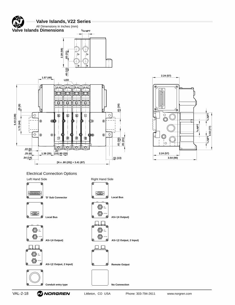
Valve Islands, V22 Series All Dimensions in Inches (mm)
VAL-2-18 Littleton, CO USA Phone: 303-794-2611 www.norgren.com
'D' Sub Connector
Conduit entry type
AS-I (4 Output)
AS-I (2 Output, 2 Input)
Local Bus
Ext
Power
AS-i Bus
Remote Output
AS-I (4 Output)
Local Bus
No Connection
Ext
Power
AS-i Bus
Ext
Power
AS-i Bus
AS-I (2 Output, 2 Input)
Ext
Power
AS-i Bus
Electrical Connection OptionsLeft Hand Side Right Hand Side
2.28
(58
)
.83
(21)
1/4 NPT
‘4’
‘2’
‘4’
‘2’
.45
(12)
5.43
(13
8)
1.73
(44
).2
5 (6
)
.80 (20).41(10)
[N x .80 (20)] + 3.41 (87)
.54 (14) .51 (13)
1.38 (35).25 (6)
1.57 (40)
.61
(16)
.81
(21)
2.24 (57)
3.54 (90)
.61
(16)
2.24 (57)
3.02
(77
)
LED
3 /8
NP
T
1 /4
NP
T1 /
4 N
PT
.22 (6)
Valve Islands Dimensions
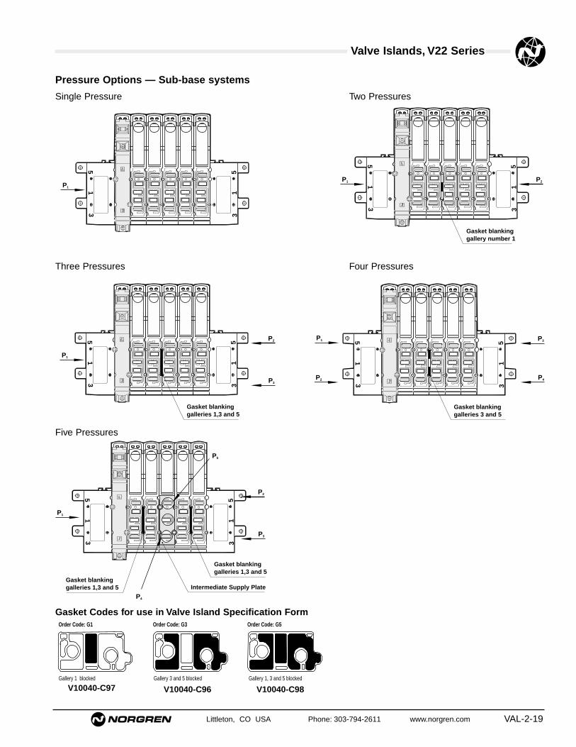
Littleton, CO USA Phone: 303-794-2611 www.norgren.com VAL-2-19
Valve Islands, V22 Series
51
3 31
5
P1
51
3 31
5
P1
Gasket blanking galleries 1,3 and 5
P2
P3
51
3 31
5
P1
Gasket blanking galleries 1,3 and 5
Gasket blanking galleries 1,3 and 5
P2
P3
P4
P5
Intermediate Supply Plate
51
3 31
5
P1 P2
Gasket blanking gallery number 1
51
3 31
5
Gasket blanking galleries 3 and 5
P1 P3
P4P2
Gallery 1 blocked Gallery 3 and 5 blocked Gallery 1, 3 and 5 blocked
Order Code: G1 Order Code: G3 Order Code: G5
Pressure Options — Sub-base systems
Gasket Codes for use in Valve Island Specification Form
Single Pressure Two Pressures
Three Pressures Four Pressures
Five Pressures
V10040-C97 V10040-C96 V10040-C98

VAL-2-20 Littleton, CO USA Phone: 303-794-2611 www.norgren.com
Valve Islands, V22 Series
V22 Valve Island Specification Form
1 2 3 4 5 6 7 8 9 10 11 12 13 14 15 16 17 18 19 20
'D' Sub connector 1" NPT Conduit AS-I (4 Output) Local bus No connection Local Bus AS-I (4 Output) Remote output
Connection options
RHS Connection
LHSConnection
Valve Codes
Gasket Codes - See Pressure Options page VAL-2-19
No. of stations required
No. of Valve Islandsrequired
Ext
Power
AS-i Bus
Ext
Power
AS-i Bus
(✓ ) (✓ ) (✓ ) (✓ ) (✓ ) (✓ ) (✓ )
AS-I(2 Output / 2 Input)
AS-I(2 Output / 2 Input)
(✓ )
(✓ )
Ext
Power
AS-i Bus
(✓ )
Ext
Power
AS-i Bus
Accessory Codes
PORT SIZEG1/4 1/4 NPT
DIN RailMntg Kit
Company____________________________________
Address ____________________________________
__________________________________________
__________________________________________
__________________________________________
Contact ____________________________________
Telephone __________________________________
Fax ________________________________________
Date________________________________________
Using the codes from the tables on page VAL-2-16, complete the build model below. Norgren will advise you of aunique part number for this assembly which can be quoted for future orders.
Valve assemblyEach valve island can be assembled with amaximum of 20 solenoids and up to 20 stations.
Fax back a copy of this order form to your local distributor.

Valve Islands, V22 Series All Dimensions in Inches (mm)
Littleton, CO USA Phone: 303-794-2611 www.norgren.com VAL-2-21
13
12
11
10
9
8
7
6
5
4
3
2
25
24
23
22
21
20
19
18
17
16
15
141
A.98 (25)
Socket
Red
A
IP40 D Sub-Connector
Type: 25 pin IP65
Model A ft (m) Weight lb (Kg)V10020–E01 3.0 (1.0) .61 (0.276)V10020–E03 10.0 (3.0) 1.49 (0.676)V10020–E05 16.0 (5.0) 2.37 (1.076)
D-Sub Connector with Cable
Pin no. Socket Plug Pin no. Socket Plug1 Solenoid 1 Red 14 Solenoid 14 Green/red2 Solenoid 2 Blue 15 Solenoid 15 Yellow/red3 Solenoid 3 Green 16 Solenoid 16 White/red4 Solenoid 4 Yellow 17 Solenoid 17 Red/black5 Solenoid 5 White 18 Solenoid 18 Red/brown6 Solenoid 6 Brown 19 Solenoid 19 Yellow/blue7 Solenoid 7 Violet 20 Solenoid 20 White/blue8 Solenoid 8 Orange 21 Not used Blue/black9 Solenoid 9 Pink 22 Not used Orange/blue10 Solenoid 10 Turquoise 23 Not used Yellow/green11 Solenoid 11 Grey 24 Common White/green12 Solenoid 12 Red/blue 25 Common Orange/green13 Solenoid 13 Black
Solenoid No. 1 is nearest to the connector on valve island
Blanking PlateV14B517A-Q2700 0.031 lbs (0.014 Kg)Blanking Plate for blocking off unwanted station. Supplied withgaskets for Sub-base mounting.
13
12
11
10
9
8
7
6
5
4
3
2
25
24
23
22
21
20
19
18
17
16
15
141
Socket
A
.98 (25)
IP65 D Sub-Connector
Type: 25 pin IP65
Model A ft (m) Weight (Kg)V11063–E01 3.0 (1.0) .61 (0.276)V11063–E03 10.0 (3.0) 1.49 (0.676)V11063–E05 16.0 (5.0) 2.37 (1.076)
D-Sub Connector with Cable
Pin no. Socket Plug Pin no. Socket Plug1 Solenoid 1 Red 14 Solenoid 14 Green/red2 Solenoid 2 Blue 15 Solenoid 15 Yellow/red3 Solenoid 3 Green 16 Solenoid 16 White/red4 Solenoid 4 Yellow 17 Solenoid 17 Red/black5 Solenoid 5 White 18 Solenoid 18 Red/brown6 Solenoid 6 Brown 19 Solenoid 19 Yellow/blue7 Solenoid 7 Violet 20 Solenoid 20 White/blue8 Solenoid 8 Orange 21 Not used Blue/black9 Solenoid 9 Pink 22 Not used Orange/blue10 Solenoid 10 Turquoise 23 Not used Yellow/green11 Solenoid 11 Grey 24 Common White/green12 Solenoid 12 Red/blue 25 Common Orange/green13 Solenoid 13 Black
Solenoid No. 1 is nearest to the connector on valve island
.24
(6)
.75
(19)
2.44 (62)

Valve Islands, V22 Series All Dimensions in Inches (mm)
VAL-2-22 Littleton, CO USA Phone: 303-794-2611 www.norgren.com
Intermediate Supply and Exhaust Module
V14B517-Q240N 0.084 lb. (0.038 Kg)1/4" NPT Provides additional porting on Modular Sub-basesystems. Occupies one valve station. Supplied with gaskets forSub-base mounting.Can be used to:Improve supply flowIncrease exhaust capacityPneumatically separate valves on Valve Island for fail safe in emergencySupply and exhaust Twin Supply Valves
.39
(10)
.75
(19)
.83 (21) .83 (21).39(10)
2.44 (62)
.34
(9)
.61
(16)
1/4 NPT
'3'
'1' '5'
DIN RailV10009-C00 0.688 lb. (0.312 Kg)3 ft (1m)
DIN Rail Mounting KitV10319–K30 0.018 lb. (0.008 Kg)Kit for mounting side ported modular sub-bases onDIN 46277-3, BS5584 and CENELEC EN 50.022 mounting rail.
1.69
(43
)A.09 (2).71 (18)
.59 (15)
LED's
2.48 (63).3
9 (1
0)2.
17 (
55)
1.38
x (3
5x)
Remote Output Modules
Application:Remote output modules are used with valve islands to provide up to4 outputs to remote devices such as Excelon Smooth Start andProspector Poppet Valves. V14, V22: 4 outputs VE1MP22B-00400
Blanking plug for unused Wireway StationV11060-K01
Identification tabsV11079-K01

● 128 I/O per node - 64 inputs and 64 outputs
● Distributed or centralized configurations
● Interchangeable protocol node
● Advanced diagnostic features
● Modular system clips together
Technical DataOperating Temperature:
32° to 122°F (0˚ to 50˚C)Vibration Tests:
To IEC 68-2-6Degree of protection:NEMA 4, IP65
EMC Standards:Generic emission standard EN50081-2Generic immunity standard EN50082-2
Materials:Main enclosure mouldings
– glass fiber reinforced polyester (PBT)Clips – Acetal Copolymer (POM)
Fieldbus II, VE2 Series
Ordering InformationTo order, complete the System SpecificationForm on page VAL-2-37 and fax to your localNorgren distributor for your free consultationservice.
Littleton, CO USA Phone: 303-794-2611 www.norgren.com VAL-2-23

VAL-2-24 Littleton, CO USA Phone: 303-794-2611 www.norgren.com
Fieldbus II, VE2 Series
24INTERBUS-S
1
5
3
2 9
4
7
24V5V
STATUS
RCRB
RDUS
5VI
incorporating
INTERBUS-S
5
6
83
3
6
5
8
6
7
2
1
6
9
Centralized Configuration
Distributed Configuration

Littleton, CO USA Phone: 303-794-2611 www.norgren.com VAL-2-25
Fieldbus II, VE2 Series
Symbol Description Part Number Code
1 Fieldbus NodeProfibus-DP VE2DPFNB-64640 F1Interbus-S VE2IBFNC-64640 F2Devicenet VE2DNFNB-64640 F3CANOpen (Available June 1999) VE2CAFNB-64640 F4
2 Common Node Sub-base
VE2FBSBA-00000 F5
3 Input/Output Modules4 outputs VE2FBOMA-00040 F68 outputs VE2FBOMA-00080 F74 NPN inputs VE2FBIMF-04000 F88 NPN inputs VE2FBIMF-08000 F94 PNP inputs VE2FBIMG-04000 F108 PNP inputs VE2FBIMG-08000 F11
4 Valve Island Interface Plates (for Fieldbus Node or Input/Output modules)Left Hand Side VE2FBVPL-00000 F12Right Hand Side (shown) VE2FBVPR-00000 F13Additional V20 kit V10075-K32 F14
5 End Cover (for Fieldbus Node or Input/Output Modules)Left Hand Side (shown) VE2FBECL-00000 F15Right Hand Side VE2FBECR-00000 F16
6 IP65 9-pin Cable Interface Plate (for Fieldbus Node or Input/Output Modules)Left Hand Side (shown) VE2FBCPL-00000 F17Right Hand Side VE2FBCPR-00000 F18
7 Valve IslandV20 F19V22 F20
8 Cable with 9-pin D-type Connectors3 ft (1m) VE2FBC9P-9S010 F2110 ft (3m) VE2FBC9P-9S030 F2216 ft (5m) VE2FBC9P-9S050 F23Wirable 9-pin D-type Connector (male) VE2FBC9P-00000 F24Wirable 9-pin D-type Connector (female) VE2FBC9S-00000 F25
9 Power Cable and Connector3 ft (1m) VE2FBCPS-M1810 F2610 ft (3m) VE2FBCPS-M1830 F2716 ft (5m) VE2FBCPS-M1850 F28Wirable Power Connector VE2FBCPS-M1800 F29
Input and Output Modules Technical SpecificationDescription 4 Inputs NPN 4 Inputs PNP 8 Inputs NPN 8 Inputs PNP 4 Outputs 8 Outputs
Part Number VE2FBIMF-04000 VE2FBIMG-04000 VE2FBIMF-08000 VE2FBIMG-08000 VE2FBOMA-00040 VE2FBOMA-00080
Connections 4 pin M12 female 4 pin M12 female 4 pin M12 female 4 pin M12 female 4 pin M12 female 4 pin M12 female1 input/connection 1 input/connection 2 inputs/connection 2 inputs/connection 1 output/connection 2 outputs/connection
Inputs Supply voltage 24V ± 10% 24V ± 10% 24V ± 10% 24V ± 10%Input On 10V-24V/3mA 10V-24V/3mA 10V-24V/3mA 10V-24V/3mAInput Off <1,5mA <1,5mA <1,5mA <1,5mAMax current load for all inputs 750mA 750mA 750mA 750mAShort circuit protected Yes Yes Yes YesOpto isolated circuits Yes Yes Yes Yes
Outputs Output voltage 24V ± 10% 24V ± 10%Max current each output 500mA 500mAMax current all outputs 750mA 750mAShort circuit protected Yes YesOpto isolated outputs Yes Yes
VE2 Components

VAL-2-26 Littleton, CO USA Phone: 303-794-2611 www.norgren.com
Fieldbus II, VE2 Series
Input M12 connecting plug and cable assemblies for sensors3 pin plug to 3 pin socket M12/Ø8 Straight/Straight 3 ft (.9) VE1FBC8S-M1210 VAL-2-39 F303 pin plug to 3 pin socket M12/Ø8 Straight/Straight 10 ft (3) VE1FBC8S-M1230 VAL-2-39 F313 pin plug to 3 pin socket M12/Ø8 Straight/Straight 16 ft (5) VE1FBC8S-M1250 VAL-2-39 F323 pin plug to 3 pin socket M12/Ø8 Straight/Elbow 3 ft (.9) VE1FBC8E-M1210 VAL-2-39 F333 pin plug to 3 pin socket M12/Ø8 Straight/Elbow 10 ft (3) VE1FBC8E-M1230 VAL-2-39 F343 pin plug to 3 pin socket M12/Ø8 Straight/Elbow 16 ft (5) VE1FBC8E-M1250 VAL-2-39 F354 pin plug to 4 pin socket M12/M12 Straight/Straight 3 ft (.9) VE1FBC0S-M1210 VAL-2-39 F364 pin plug to 4 pin socket M12/M12 Straight/Straight 10 ft (3) VE1FBC0S-M1230 VAL-2-39 F374 pin plug to 4 pin socket M12/M12 Straight/Straight 16 ft (5) VE1FBC0S-M1250 VAL-2-39 F383 pin plug to 2x3 pin socket M12/Ø8 Straight/Straight 3 ft (.9) VE1FBC8S-M121D VAL-2-39 F393 pin plug to 2x3 pin socket M12/Ø8 Straight/Straight 10 ft (3) VE1FBC8S-M123D VAL-2-39 F403 pin plug to 2x3 pin socket M12/Ø8 Straight/Straight 16 ft (5) VE1FBC8S-M125D VAL-2-39 F413 pin plug to 2x3 pin socket M12/Ø8 Straight/Elbow 3 ft (.9) VE1FBC8E-M121D VAL-2-39 F423 pin plug to 2x3 pin socket M12/Ø8 Straight/Elbow 10 ft (3) VE1FBC8E-M123D VAL-2-39 F433 pin plug to 2x3 pin socket M12/Ø8 Straight/Elbow 16 ft (5) VE1FBC8E-M125D VAL-2-39 F444 pin plug to 2x4 pin socket M12/M12 Straight/Straight 3 ft (.9) VE1FBC0S-M121D VAL-2-39 F454 pin plug to 2x4 pin socket M12/M12 Straight/Straight 10 ft (3) VE1FBC0S-M123D VAL-2-39 F464 pin plug to 2x4 pin socket M12/M12 Straight/Straight 16 ft (5) VE1FBC0S-M125D VAL-2-39 F47
Input or Output M12 plug
Wirable 5 pin male – screw termination M12 Straight - VE1FBCRS-M125P VAL-2-40 F48
Output M12 plug and connecting cables for solenoid coils*5 pin plug to valve connection – Type C (15mm coil) M12 Straight 1 ft (.3) VE1FBCSC-M1203 VAL-2-40 F495 pin plug to valve connection – Type C (15mm coil) M12 Straight 3 ft (.9) VE1FBCSC-M1210 VAL-2-40 F505 pin plug to valve connection – Industrial (22mm coil) M12 Straight 1 ft (.3) VE1FBCSB-M1203 VAL-2-40 F515 pin plug to valve connection – Industrial (22mm coil) M12 Straight 3 ft (.9) VE1FBCSB-M1210 VAL-2-40 F525 pin plug to valve connection – Type A (32mm coil) M12 Straight 1 ft (.3) VE1FBCSA-M1203 VAL-2-40 F535 pin plug to valve connection – Type A (32mm coil) M12 Straight 3 ft (.9) VE1FBCSA-M1210 VAL-2-40 F545 pin plug to 2 valve connections – Type C (15mm coil) M12 Straight 1 ft (.3) VE1FBCTC-M1203 VAL-2-40 F555 pin plug to 2 valve connections – Type C (15mm coil) M12 Straight 3 ft (.9) VE1FBCTC-M1210 VAL-2-40 F565 pin plug to 2 valve connections – Industrial (22mm coil) M12 Straight 1 ft (.3) VE1FBCTB-M1203 VAL-2-40 F575 pin plug to 2 valve connections – Industrial (22mm coil) M12 Straight 3 ft (.9) VE1FBCTB-M1210 VAL-2-40 F585 pin plug to 2 valve connections – Type A (32mm coil) M12 Straight 1 ft (.3) VE1FBCTA-M1203 VAL-2-40 F595 pin plug to 2 valve connections – Type A (32mm coil) M12 Straight 3 ft (.9) VE1FBCTA-M1210 VAL-2-40 F60
Wirable communication cable connectorsProfibus-DP 12 pin Coninver male ø22mm Straight N/A VE1DPCRS-CN12P VAL-2-40 F61Interbus-S 9 pin Coninver female ø22mm Straight N/A VE1IBCRS-CN09S VAL-2-40 F62Interbus-S 9 pin Coninver male ø22mm Straight N/A VE1IBCRS-CN09P VAL-2-40 F63
* Each coil plug has LED and suppression as standard.
Accessories
Symbol Description Connection Straight/Elbow Cable Length Part Number Detail Codesize (meters)

Littleton, CO USA Phone: 303-794-2611 www.norgren.com VAL-2-27
Fieldbus II, VE2 Series
Protocol Connector Type(s) Node Part Number Communication Max Baud Rate Node Details Connector Details
Network Data
MODE
SET
MODE
SET
MODE
SET
MODE
SET
24V5V
STATUS
RCRB
RDUS
5VI
incorporating
INTERBUS-S
24V5V
STATUS
RCRB
RDUS
5VI
incorporating
INTERBUS-S
Standard ProductsProfibus-DP 1xConinver (IP65) VE2DPFNB-64640 RS485 12Mb/s VAL-2-29 VAL-2-38Interbus-S 2xConinver (IP65) VE2IBFNC-64640 RS422 500Kb/s VAL-2-30 VAL-2-38Devicenet 1x Micro-Change (IP65) VE2DNFNB-64640 CAN 500Kb/s VAL-2-31 Local StockistCANopen (Available June 1999) 1xMicro-Change (IP65) VE2CAFNB-64640 CAN 1Mb/s VAL-2-31 Local Stockist
Alternative Connection OptionsProfibus-DP (F1D) 1xD-Type (IP65) VE2DPFND-64640 RS485 12Mb/s VAL-2-29 VAL-2-38Interbus-S (F2D) 2xD-Type (IP65) VE2IBFNE-64640 RS422 500Kb/s VAL-2-30 VAL-2-38
Centralized
Distributed
PLC
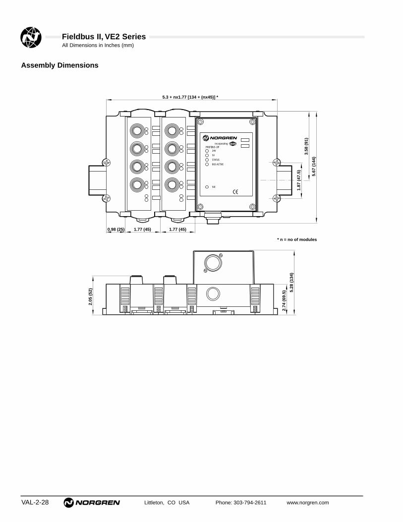
Fieldbus II, VE2 SeriesAll Dimensions in Inches (mm)
VAL-2-28 Littleton, CO USA Phone: 303-794-2611 www.norgren.com
Assembly Dimensions
incorporating
24V
5V
STATUS
BUS ACTIVE
5VI
PROFIBUS-DP
2.05
(52
)
2.74
(69
.5) 5.
28 (
134)
5.3 + nx1.77 [134 + (nx45)] *
0.98 (25) 1.77 (45) 1.77 (45)
1.87
(47
.5)
3.58
(91
)
5.67
(14
4)
* n = no of modules

Fieldbus II, VE2 SeriesAll Dimensions in Inches (mm)
Littleton, CO USA Phone: 303-794-2611 www.norgren.com VAL-2-29
Profibus-DP Fieldbus NodeSingle Coninver Connector (standard)VE2DPFNB-64640
incorporating
24V
5V
STATUS
BUS ACTIVE
5VI
PROFIBUS-DP
1.10
(28
)
0.55 (14)
2.72 (69)
3.19 (81)
4.45
(11
3)
4.92
(12
5)
1.73 (44)
Profibus Node Accessories
Wirable 12 pin coninver typeconnector (NEMA 4, IP65)
Part Number
VE1DPCRS-CN12P Male
Profibus-DP Fieldbus NodeSingle D-Type Connector (option)VE2DPFND-64640
Profibus Node Accessories
Wirable 9 pin D-Typeconnector (NEMA 4, IP65)
Part Number
VE2FBC9P-00000 Male
24V
5V
STATUS
BUS ACTIVE
5VI
incorporatingPROFIBUS-DP
1.10
(28)
0.37
(9.5
)
0.63 (16)
2.72 (69)
3.19 (81)
4.45
(11
3)
4.92
(12
5)
1.73 (44)

Fieldbus II, VE2 SeriesAll Dimensions in Inches (mm)
VAL-2-30 Littleton, CO USA Phone: 303-794-2611 www.norgren.com
Interbus-S Fieldbus NodeDouble Coninver Type Connectors (standard)VE2IBFNC-64640
24V
5V
STATUS
RC
RB
RD
US
5VI
incorporatingINTERBUS-S
1.10
(28
)
0.55(14)
0.55 (14)
2.72 (69)
3.19 (81)
4.45
(11
3)
4.92
(12
5)
1.73 (44)
Interbus-S Fieldbus NodeDouble D-Type Connectors (option)VE2IBFNE-64640
24V
5V
STATUS
RC
RB
RD
US
5VI
incorporatingINTERBUS-S
1.10
(28)
0.37
(9
.5)
0.63(16)
0.63 (16)
2.72 (69)
3.19 (81)
4.45
(11
3)
4.92
(12
5)
1.73 (44) Interbus-S Node Accessories
Wirable D-Type IP65 connector
Part Number
VE2FBC9P-00000 MaleVE2FBC9S-00000 Female
Interbus-S Node Accessories
Wirable Interbus-S 9-pinconnector
Part Number
VE1IBCRS-CN09P MaleVE1IBCRS-CN09S Female

Fieldbus II, VE2 SeriesAll Dimensions in Inches (mm)
Littleton, CO USA Phone: 303-794-2611 www.norgren.com VAL-2-31
DeviceNet Fieldbus NodeSingle Micro Change Type Connector (standard)VE2DNFNB-64640
incorporating
24V
5V
MODULE STATUS
NETWORK STATUS
I/O STATUS
5VI
DEVICENET
1.10
(28
)
1.02 (26)
2.72 (69)
3.19 (81)4.
45 (
113)
4.92
(12
5)1.73 (44)
CANopen Fieldbus NodeSingle Micro Change Type Connector (standard)VE2CAFNB-64640
incorporating
24V
5V
MODULE STATUS
NETWORK STATUS
I/O STATUS
5VI
DEVICENET
1.10
(28
)
1.02 (26)
2.72 (69)
3.19 (81)
4.45
(11
3)
4.92
(12
5)
1.73 (44)

Fieldbus II, VE2 SeriesAll Dimensions in Inches (mm)
VAL-2-32 Littleton, CO USA Phone: 303-794-2611 www.norgren.com
Common Node Sub-baseVE2FBSBA-00000
incorporating
24V5V
STATUS
BUS ACTIVE
5VI
PROFIBUS-DP
1.06
(27
)
1.06 (27)
114
5.90
(15
0)
5.49
(13
9.5)
2.74 (69.5)
3.31 (84)
2.74 (69.5)
3.31 (84)
Common Node Accessories
Power cable with 4 pole femaleconnector and hood
Part Number
VE2FBCPS-M1810 3 ftVE2FBCPS-M1830 10 ftVE2FBCPS-M1850 16 ft
Wirable 4 pole femaleconnector and hood
Part Number
VE2FBCPS-M1800

Fieldbus II, VE2 SeriesAll Dimensions in Inches (mm)
Littleton, CO USA Phone: 303-794-2611 www.norgren.com VAL-2-33
Input and Output Modules
incorporating
PowerStatus
OUTPUT – 8PNP
1.59
(40
.5)
1.99
(50
.5)
2.05
(52
)
5.79
(14
7)
1.77 (45)
1.18 (30)
0.71(18)
1
4 3
2
1
4 3
2
5
Mechanical switchReed switch
3-wire-pnp-sensor
2-wire-pnp-sensor
2-wire-solenoid-idle run diode recommended
L+
A1
4
4
3
1+-Signal
1
4
+
Signal
4
3
+
-
Module/Socket view
Module/Socket view
Pin1 Sensor supply +3 Sensor supply -4 Signal input
Pin4 Switch output +3 External voltage -
4 Pin input connection
3 Pin output connection
VE2FBIMF-08000 8 Inputs NPNVE2FBIMG-08000 8 Inputs PNPVE2FBOMA-00080 8 Outputs
1
4 3
2
1
4 3
2
5
Mechanical switchReed switch
3-wire-pnp-sensor
2-wire-pnp-sensor
2-wire-solenoid-idle run diode recommended
L+
A1
4 or 2
4 or 2
3
1+-Signal
1
4 or 2
+
Signal
4 or 2
3
+
-
Module/Socket view
Module/Socket view
Pin1 Sensor supply +3 Sensor supply -2+4 Signal input
Pin2+4 Switch output +3 External voltage -
4 Pin input connection
3 Pin output connection
VE2FBIMF-04000 4 Inputs NPNVE2FBIMG-04000 4 Inputs PNPVE2FBOMA-00040 4 Outputs

Fieldbus II, VE2 SeriesAll Dimensions in Inches (mm)
VAL-2-34 Littleton, CO USA Phone: 303-794-2611 www.norgren.com
Valve Island Interface PlateFor connection between Common Node Sub-base or Input/Output Module and Valve Island
LHS
RHS
Left Hand Side (LHS)VE2FBVPL-00000
Additional V20 kitV10075-K32
Right Hand Side (RHS)VE2FBVPR-00000
5.51 (140)
1.38 (35)0.98 (25)
1.12 (28.5)
0.98 (25)
1.59
(40
.5)
5.51 (140)
1.38 (35) 0.98 (25)
1.12 (28.5)
0.98 (25)
1.59
(40
.5)
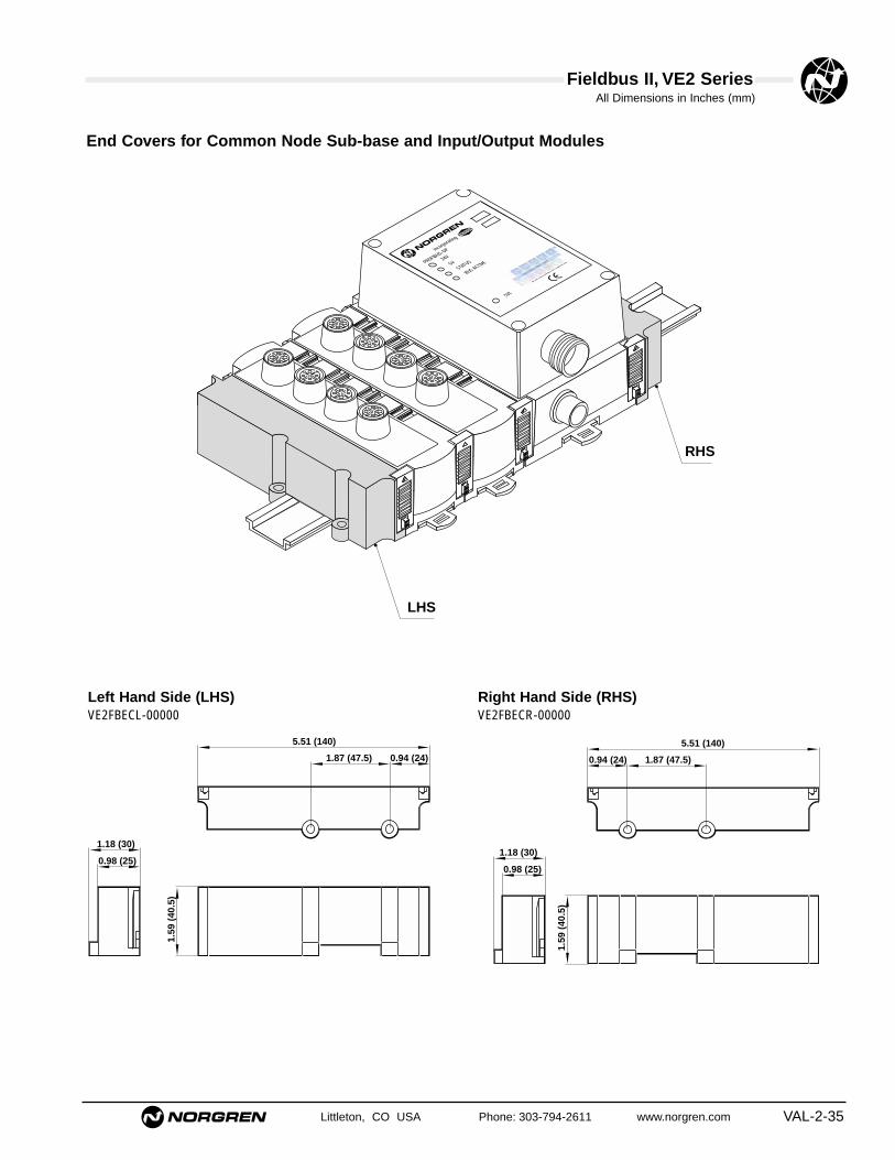
Fieldbus II, VE2 SeriesAll Dimensions in Inches (mm)
Littleton, CO USA Phone: 303-794-2611 www.norgren.com VAL-2-35
End Covers for Common Node Sub-base and Input/Output Modules
incorporating
24V5V
STATUS
BUS ACTIVE
5VI
PROFIBUS-DP
LHS
RHS
Left Hand Side (LHS)VE2FBECL-00000
Right Hand Side (RHS)VE2FBECR-00000
5.51 (140)
0.94 (24)1.87 (47.5)
1.18 (30)
0.98 (25)
1.59
(40
.5)
5.51 (140)
0.94 (24) 1.87 (47.5)
1.18 (30)
0.98 (25)
1.59
(40
.5)

Fieldbus II, VE2 SeriesAll Dimensions in Inches (mm)
VAL-2-36 Littleton, CO USA Phone: 303-794-2611 www.norgren.com
9-pin Cable Interface PlateFor Common Node Sub-base and Input/Output Modules
incorporating
24V5V
STATUS
BUS ACTIVE
5VI
PROFIBUS-DP
LHS
LHS
RHS
RHS
Left Hand Side (LHS)VE2FBCPL-00000
Right Hand Side (RHS)VE2FBCPR-00000
5.51 (140)
0.94 (24)1.87 (47.5)
1.18 (30)
0.98 (25)
1.59
(40
.5)
5.51 (140)
0.94 (24) 1.87 (47.5)
1.18 (30)
0.98 (25)
1.59
(40
.5)
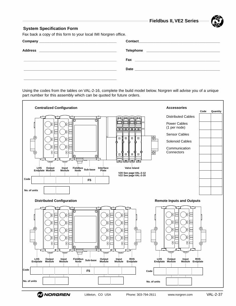
Littleton, CO USA Phone: 303-794-2611 www.norgren.com VAL-2-37
Fieldbus II, VE2 Series
System Specification Form
LHSEndplate
Valve Island
V20 See page VAL-2-12V22 See page VAL-2-20
OutputModule
InputModule Sub-base
FieldbusNode
InterfacePlate
LHSEndplate
OutputModule
InputModule
RHSEndplate
LHSEndplate
RHSEndplate
OutputModule
InputModule
FieldbusNode
OutputModule
InputModule
Remote Inputs and OutputsDistributed Configuration
Centralized Configuration
Sub-base
Accessories
Distributed Cables
Power Cables (1 per node)
Sensor Cables
Solenoid Cables
Communication Connectors
Code F5
No. of units
Code F5
No. of units
Code
No. of units
Fax back a copy of this form to your local IMI Norgren office.
Company ________________________________________
Address ________________________________________
________________________________________________
________________________________________________
________________________________________________
Contact__________________________________________
Telephone ______________________________________
Fax ____________________________________________
Date ____________________________________________
Using the codes from the tables on VAL-2-16, complete the build model below. Norgren will advise you of a uniquepart number for this assembly which can be quoted for future orders.
Code Quantity

Fieldbus II, VE2 SeriesAll Dimensions in Inches (mm)
VAL-2-38 Littleton, CO USA Phone: 303-794-2611 www.norgren.com
0.67 (17)
2.13 (54)
Ø1.
0025
.5
1
4 3
2
2.13 (54)'L'0.98 (25)
Ø 1.00(25.5)
Power supply cables and connectors (For common node sub-base)
Cable and connector assemblies (IP65, NEMA 4)VE2FBCPS-M1810 L = 3 ftVE2FBCPS-M1830 L = 10 ftVE2FBCPS-M1850 L = 16 ft
Wirable Power Supply Connector (IP65, NEMA 4)VE2FBCPS-M1800
1.10 (28)
2.17 (55) 'L'
0.83(21)
1.67
(42
.5)
Distributed SystemsCable with 9-pin D-Type Connectors (IP65, NEMA 4)VE2FBC9P-9S010 L = 3 ftVE2FBC9P-9S030 L = 10 ftVE2FBC9P-9S050 L = 16 ft
Wirable 9-pin D-Type Connectors (IP65, NEMA 4)
VE2FBC9P-00000 maleVE2FBC9S-00000 female
1.10 (28)
2.17 (55)
0.83(21)
1.67
(42
.5)
Pin No 9 Pin 9 Pin Colour Male Female D-type D-type
1 24 Volt A 24 Volt A Red & Brown5 0V24 024V White
4 24 Volt B 24 Volt B White5 0V24 0V24 Black
2 5 Volt 5Volt Blue3 0V5 0V5 Black
9 A A Green7 B B Black
8 Config Out Config In Yellow6 Config Rtn Config Rtn Black
Shell Shell ScreenCable specification:Beldon 9506 CMG 6pr24 Shielded
Wirable communication cable connectors (IP65, NEMA 4)VE1DPCRS-CN12P Profibus-DP 12 pin coninver maleVE1IBCRS-CN09S Interbus-S 9 pin coninver femaleVE1IBCRS-CN09P Interbus-S 9 pin coninver male
2.00 (51)
ø1.02 (26)
ø0.39(10) max

Fieldbus II, VE2 SeriesAll Dimensions in Inches (mm)
Littleton, CO USA Phone: 303-794-2611 www.norgren.com VAL-2-39
Input M12 plug and cable assemblies for sensors
1.14 (29)
1.20 (30.5)'L'1.63 (41.5)
M12 Male connectormale thread
Ø 0.31(8) Female connector
Ø 0
.31
(8)
Faceview
4
3 1
2
13
4
Faceview
3 pin plug to 3 pin socket – straight connectorsVE1FBC8S-M1210 L = 3 ftVE1FBC8S-M1230 L = 10 ftVE1FBC8S-M1250 L = 16 ft
0.79(20)
0.24(6)'L'1.63 (41.5)
M12 Male connectormale thread
Ø 0.31 (8) Female right angledconnector
16
Faceview
43
1
2
13
4
Faceview
0.31 (8)
3 pin plug to 3 pin socketVE1FBC8E-M1210 L = 3 ftVE1FBC8E-M1230 L = 10 ftVE1FBC8E-M1250 L = 16 ft
0.24(6)
'L'1.63 (41.5)
M12 Male connectormale thread
Ø 0.31(8) Female right angledconnector
0.63
(16)
Faceview 4
3
1
2
13
4
Faceview
0.31 (8)
0.79 (20)
3 pin plug to 2x3 pin socket right angle connectorVE1FBC8E-M121D L = 3 ftVE1FBC8E-M123D L = 10 ftVE1FBC8E-M125D L = 16 ft
Ø0.58(14.7)
M12 or M8 straightor M8 elbow
4
1 3
2'L'1.63 (41.5)
M12 Male connectormale thread
1.39 (35.2)
4 pin plug to 2x4 pin socket straight connectorVE1FBC0S-M121D L = 3 ftVE1FBC0S-M123D L = 10 ftVE1FBC0S-M125D L = 16 ft
1.39 (35.2)1.62 (41.2) L
Ø 0.58 (14.7)Ø 0.58 (14.7)
12mm Male connectormale thread
12mm Female connectorfemale thread
4
1 3
2
4
13
2
4 pin plug to 4 pin socket straight connectorVE1FBC0S-M1210 L = 3 ftVE1FBC0S-M1230 L = 10 ftVE1FBC0S-M1250 L = 16 ft
1.14 (29)
1.20 (30.5)'L'1.63 (41.5)
M12 Male connectormale thread
Ø 0.31(8) Female connector
Ø0.
31(8
)
Faceview
4
3 12
13
4
Faceview
3 pin plug to 2x3 pin socket straight connectorVE1FBC8S-M121D L = 3 ftVE1FBC8S-M123D L = 10 ftVE1FBC8S-M125D L = 16 ft
Input M12 plug and cable assemblies for sensors

Fieldbus II, VE2 SeriesAll Dimensions in Inches (mm)
VAL-2-40 Littleton, CO USA Phone: 303-794-2611 www.norgren.com
1.84(46.7)
1.18(30) 'L'
Solenoid 1
Solenoid 2
45°
Ø0.
80(2
0.2)
1 34
2Faceview
12mm Male connectormale thread M
12x1
Form 'C' solenoid connector shown
5 pin plug to 2 valve connectionsVE1FBCTC-M1203 L = 1 ft cable, Type ‘C’ connectorVE1FBCTC-M1210 L = 3 ft cable, Type ‘C’ connectorVE1FBCTB-M1203 L = 1 ft cable, Industrial connectorVE1FBCTB-M1210 L = 3 ft cable, Industrial connectorVE1FBCTA-M1203 L = 1 ft cable, Type ‘A’ connectorVE1FBCTA-M1210 L = 3 ft cable, Type ‘A’ connector
Ø0.
79(2
0)2.16 (55)
12mm male connectormale thread
2
1
4
3
5
Faceview
PG7 gland
Wirable Input or output 5 pin male plug – screwtermination VE1FBCRS-M125P
1.18 (30)'L'1.63 (41.5)
M12 Male connectormale thread
Form 'C'Solenoid connector
4
1 3
5
2
FaceView
5 pin plug to valve connectionVE1FBCSC-M1203 L = 1 ft cable, Type ‘C’ connectorVE1FBCSC-M1210 L = 3 ft cable, Type ‘C’ connectorVE1FBCSB-M1203 L = 1 ft cable, Industrial connectorVE1FBCSB-M1210 L = 3 ft cable, Industrial connectorVE1FBCSA-M1203 L = 1 ft cable, Type ‘A’ connectorVE1FBCSA-M1210 L = 3 ft cable, Type ‘A’ connector
Input and Output M12 plug and cable assemblies for solenoid coils
Coil plugs are fitted with LED and suppression as standard

Littleton, CO USA Phone: 303-794-2611 www.norgren.com VAL-2-41
Glossary
Address – Part of the message sent by the Fieldbus Controller is concerned withthe device address. Each address is unique, and specifies the location of each valvedriver and the solenoid position for the valve.Analogue / Digital – Analogue signals are continuously variable (as is sound in thereal world). Computers find it difficult to use analogue signals, so signals areconverted into a digital form.ASIC – Application Specific Integrated Circuits. These are designed for electroniccircuits for use within a specific Fieldbus system. i.e. an ASIC for one type of systemcannot usually be used with another.Baud Rate – The speed at which digital information is transmitted. Baud rate ismeasured in bits/sec.Bi-directional – Refers to the fact that messages can be sent in both directionsalong the same wires.Binary – A mathematical system whereby the digits 0 and 1 are used to represent acharacter or piece of data in a computer. The electrical signals inside the computercan be thought of having only two states; signal off and signal on (0 and 1respectively).Bit/Byte/Word – A bit is a computing unit expressed as a choice of 0 or 1 (in basicterms - signal off or on). Bit actually stands for Binary DigitByte – A group of eight bits. The lowest bit (rightmost)_ is equal to 0 or 1 and thehighest bit is equal to 0 of 128. The highest value that one byte can represent is 255 (or 256 states). i.e. 128 + 64 + 32 + 16 + 8 + 4 + 2 + 1 = 255Word – A group of sixteen bits. Words are used in 16 bit computers and many PLCdata stores. A word can represent in binary form a maximum value of 65535 (or65536 states).Communication Bus – A physical link over which data is transmitted betweensuitable devices. The bus may be a wire, fiber optic, or radio wave.Diagnostics – A way of receiving information on faults or problems betweendevices. This is achieved by using visible indicators on or inside the Fieldbus unit orby communication between devices. i.e. if a program finds a fault, it may beinstructed to reset the system or possibly to wait for further instruction from anoperator.Fieldbus – Also bus. A data link (usually in the form of a cable) on which electricaldevices communicate with each other for control purposes. In Pneumatic systems,Fieldbus linked drivers, operate valves or other remote devices. Feedback fromsensors is provided by Input Modules.Hexadecimal – A mathematical system where each character can represent a valueup to 15 (i.e. 16 states). i.e. Hex 0,1,2,3,4,5,6,7,8,9,A,B,C,D,E,F.I/O – Also Input/Output. The I/O is the physical connection between a controller andthe equipment that it controls. The connected inputs may be switches, proximitydevices or analogue sensors. Outputs may be relays, pneumatic solenoid coils oranalogue devices. The Input module also serves as a barrier against harsh spikesand noise often experienced in an industrial environment. It may contain opto-isolators which protect the CPU from large input surges.IP rating – Provides a means of classifying the degrees of protection from dust,water and impact afforded by electrical equipment enclosures. It is common practicefor manufacturers to apply ratings for only the first two numerals.IP40 and IP65 – IP40 protects against solid objects over 1 mm (such as tools, wires,fingers), but has no protection against ingress of liquids. IP65 totally protects againstdust and low pressure water jets from all directions.Ladder Logic – A method of describing an electrical circuit in logic symbols andrelay-based ladder diagrams. It is the usual way to program PLC’s.Line Bus – A line bus doesMaster – A controller connected to a bus which issues messages to other deviceson the same but. Masters contain programs to logically control processes and canbe a PLC, PC or other control device.Supervisory Master – A controller which only concerns itself with the inputs andignores all the outputs.PLC – Programmable Logic ControllerSlave – A device connected to a bus which only responds when a messageintended for itself is received. Except for a reply to that message, it can not accessthe bus. The common name for the valve driver or input module.Repeater – A device which can either boost the signal generated by a fieldbusmaster (in order that slaves can be positioned further from the signal source): or itmay allow a greater number of devices to be connected to a Fieldbus system.Valve Manifold – Replaces the manifold solenoid valve bank. A combination ofsystem valves, usually with a multipole, configured specifically to meet customersneeds.Gateway – A converter which allows systems running two different protocols tocommunicate with each other: in effect a translator.Ladder logic – A method of describing an electrical circuit in logic symbols andrelay-based ladder diagrams. It is the usual way to program PLC’s.
Line bus – A line bus does not form a closed loop circuit.With the line bus networks Norgren promotes, all thestations are daisy chain together to overcome a problemassociated with Spur distances. Although both a line-in andline-out are provided, they are effectively connected insidethe Fieldbus units. However, DeviceNet units tap directly offthe communication bus with t-pieces.Ring bus – Also Closed loop. All stations in a system arelinked into a physical ring. With Interbus-S the link passesthrough each station in turn and each station is therefore anintegral part of the transmission path. The data makes onetrip around the ring, passed from station to station. Eachstation checks whether the data is addressed to it. Whenthis is the case, the station copies the data into its ownmemory.Tree bus – Does not form a closed loop. Each station islinked to the transmission path by cables as required. UnlikeLine bus, a Tree bus is more flexible because thecommunication can be laid out into any convenient shape.Multi-drop – Refers to a communications system which hastwo or more devices connected to it off a bus (i.e. more thanone device can be connected to it).NEMA 4 – An American Standard for water penetration.Multipole – A connector in which all the individual wires fordevices are combined in a cable which has en integral multi-pin connector for quick connection and installation in asystem. i.e. a printer cable for connection to a computeremploys a similar principle.Noise – Electrical interference, usually in the form of highvoltage spikes or radio signals caused by unscreened orunsurpressed equipment. Noise can cause corruption ofdata during transmission or malfunction of electroniccomponents.Open System – For a system to function properly, alldevices must be compatible. With Open systems, thetechnology (or protocol) is available to allow manufacturersto build compatible equipment.Closed System – Also In-House or Proprietary system. Amanufacturer develops the technology (or protocol) that isunique to him. Closed systems are therefore companyspecific and usually non-compatible with other types. ClosedNorgren systems are: Pneubus, Sysmac, Jetterbus.Opto-isolator – Separates harsh industrial signals fromsensitive components in a controller or slave. This isachieved by converting the signal to light. The externalsignal is transmitted as light to a light sensitive receiver.This in turn converts the light back into an electrical signal.Protocol – Defines the content and structure of a Fieldbusmessage. The differences between each Fieldbus protocolcan be considered in the same way as those betweenlanguages.RS232, RS422, RS485 – American Standards for theelectrical characteristics of a link. The standard specifies thedigit state values. Links are used in the digital transmissionof data between electronic equipment.RAM / ROM / EEPROM –
RAM – Random Access Memory. RAM is used internallyby a PC or PLC as a short term store for data, programvariables and control codes. It is volatile and as such willlose all its data when power is removed. Therefore, RAMused for programs is battery backed.ROM – Read ONly Memory. ROM is pre-programmed bythe manufacturer. It holds the controller system memoryand instructions for its operation. It cannot be altered. It isnon-volatile; when power is removed a ROM retains all itsinformation.EEPROM – Electrically Erasable Programmable ReadOnly Memory. EEPROM’s are used to store the userprogram. They can be erased and programmed withrelative ease. As with ROMS. EEPROM’s do not lose theircontents when power is removed and as such they arenon-volatile.

Littleton, CO USA Phone: 303-794-2611 www.norgren.com VAL-3-1
Section 3
ContentsTechnical Data ........................................................................VAL-3-23/2 Solenoid Pilot Valves .......................................................VAL-3-32 x 3/2 Solenoid Pilot Valves .................................................VAL-3-55/2 Solenoid Pilot Valves .......................................................VAL-3-75/3 Solenoid Pilot Valves .......................................................VAL-3-93/2 Solenoid Pilot Valves .....................................................VAL-3-112 x 3/2 Air Pilot Valves .........................................................VAL-3-115/2 Air Pilot Valves................................................................VAL-3-135/3 Air Pilot Valves................................................................VAL-3-13Manifold System ...................................................................VAL-3-15Mounting Instructions..........................................................VAL-3-16Product Numbering System ................................................VAL-3-17
V60, V61, and V623/2, 5/2, 5/3 and 2 x 3/2 Directional Control Valves

V60 Series
● High flow rate
● Manual override option
● Manifold system for easy assembly
● Low power consumption
● Maintenance-free
3/2, 5/2, 5/3 and 2 x 3/2 Directional control valves
Technical dataMedium:
Compressed air, filtered to 50 µm, lubricated or non-lubricated.
Operation: Solenoid pilot or air pilot operated
Mounting: Individual or fixed length manifoldConnection:
1/8" NPT up to 3/8" NPTOperating pressure: Maximum pressure 116 to 145 psi (8 to 10 bar)Flow direction:
Internal pilot supply: fixedExternal pilot supply: optional
Flow: Size NPT 3/2, 5/2 2 x 3/2, 5/3
Cv (l/min) Cv (l/min)1/8 .75 (750) .50 (500)1/4 1.3 (1300) .95 (950)3/8 2.6 (2600) 1.9 (1900)Ambient temperature:14°F to +122°F (-10°C to +50°C) Fluid temperature:14°F to +122°F (-10°C to +50°C)Consult our Technical Service for use below 36°F (+2°C).
Materials Housing and base plate: aluminum
Spindle: stainless steel,Piston, spacers and cover: synthetic materialStatic and dynamic seals: NBR Screws: zinc platedSprings: stainless steel
Alternative modelsISO G ports.
VAL-3-2 Littleton, CO USA Phone: 303-794-2611 www.norgren.com

V60 Series
Littleton, CO USA Phone: 303-794-2611 www.norgren.com VAL-3-3
V60P417A-Ax**** 1/8 Internal Not collected Primary 0.75 (750) 29 to 116 (2 to 8) – 0.49 (.22) 1 V60P427A-Ax**** 1/8 External Not collected Primary 0.75 (750) 26" Hg to 116 (-0.9 to 8) 44 to 116 (3 to 8) 0.49 (.22) 1 V60P417D-Cx13AA 1/8 Internal Collected Secondary 0.75 (750) 29 to 145 (2 to 10) – 0.46 (.21) 4 V60P427D-Cx13AA 1/8 External Collected Secondary 0.75 (750) 26" Hg to 145 (-0.9 to 10) 44 to 145 (3 to 10) 0.46 (.21) 4 V61B417A-Ax**** 1/4 Internal Not collected Primary 1.30 (1300) 29 to 116 (2 to 8) – 0.64 (.29) 1 V61B427A-Ax**** 1/4 External Not collected Primary 1.30 (1300) 26" Hg to 116 (-0.9 to 8) 44 to 116 (3 to 8) 0.64 (.29) 1 V61B417D-Cx13AA 1/4 Internal Collected Secondary 1.30 (1300) 29 to 145 (2 to 10) – 0.60 (.27) 4 V61B427D-Cx13AA 1/4 External Collected Secondary 1.30 (1300) 26" Hg to 145 (-0.9 to 10) 44 to 145 (3 to 10) 0.60 (.27) 4 V62S417A-Ax**** 3/8 Internal Not collected Primary 2.60 (2600) 29 to 116 (2 to 8) – 1.15 (.52) 1 V62S427A-Ax**** 3/8 External Not collected Primary 2.60 (2600) 26" Hg to 116 (-0.9 to 8) 44 to 116 (3 to 8) 1.15 (.52) 1 V62S417D-Cx13AA 3/8 Internal Collected Secondary 2.60 (2600) 29 to 145 (2 to 10) – 1.10 (.50) 4 V62S427D-Cx13AA 3/8 External Collected Secondary 2.60 (2600) 26" Hg to 145 (-0.9 to 10) 44 to 145 (3 to 10) 1.10 (.50) 4 V60P317A-Ax**** 1/8 Internal Not collected Primary 0.75 (750) 29 to 116 (2 to 8) – 0.5 (.22) 2 V60P327A-Ax**** 1/8 External Not collected Primary 0.75 (750) 26" Hg to 116 (-0.9 to 8) 44 to 116 (3 to 8) 0.5 (.22) 2V60P317D-Cx13AA 1/8 Internal Collected Secondary 0.75 (750) 29 to 145 (2 to 10) – 0.5 (.21) 4 V60P327D-Cx13AA 1/8 External Collected Secondary 0.75 (750) 26" Hg to 145 (-0.9 to 10) 44 to 145 (3 to 10) 0.5 (.21) 4 V61R317A-Ax**** 1/4 Internal Not collected Primary 1.30 (1300) 29 to 116 (2 to 8) – 0.64 (.29) 2 V61R327A-Ax**** 1/4 External Not collected Primary 1.30 (1300) 26" Hg to 116 (-0.9 to 8) 44 to 116 (3 to 8) 0.64 (.29) 2 V61R317D-Cx13AA 1/4 Internal Collected Secondary 1.30 (1300) 29 to 145 (2 to 10) – 0.60 (.27) 4 V61R327D-Cx13AA 1/4 External Collected Secondary 1.30 (1300) 26" Hg to 145 (-0.9 to 10) 44 to 145 (3 to 10) 0.60 (.27) 4 V62S317A-Ax**** 3/8 Internal Not collected Primary 2.60 (2600) 29 to 116 (2 to 8) – 1.15 (.52) 2 V62S327A-Ax**** 3/8 External Not collected Primary 2.60 (2600) 26" Hg to 116 (-0.9 to 8) 44 to 116 (3 to 8) 1.15 (.52) 2 V62S317D-Cx13AA 3/8 Internal Collected Secondary 2.60 (2600) 29 to 145 (2 to 10) – 1.10 (.50) 4 V62S327D-Cx13AA 3/8 External Collected Secondary 2.60 (2600) 26" Hg to 145 (-0.9 to 10) 44 to 145 (3 to 10) 1.10 (.50) 4 V60P411A-Ax**** 1/8 Internal Not collected Primary 0.75 (750) 22 to 116 (1.5 to 8) – .66 (.30) 3 V60P422A-Ax**** 1/8 External Not collected Primary 0.75 (750) 26" Hg to 116 (-0.9 to 8) 44 to 116 (3 to 8) .66 (.30) 3 V60P411D-Cx13AA 1/8 Internal Collected Secondary 0.75 (750) 22 to 145 (1.5 to 10) – .44 (.20) 4 V60P422D-Cx13AA 1/8 External Collected Secondary 0.75 (750) 26" Hg to 145 (-0.9 to 10) 44 to 145 (3 to 10) .44 (.20 4 V61R411A-Ax**** 1/4 Internal Not collected Primary 1.30 (1300) 22 to 116 (1.5 to 8) – 0.84 (.38) 3 V61R422A-Ax**** 1/4 External Not collected Primary 1.30 (1300) 26" Hg to 116 (-0.9 to 8) 44 to 116 (3 to 8) 0.84 (.38) 3 V61R411D-Cx13AA 1/4 Internal Collected Secondary 1.30 (1300) 22 to 145 (1.5 to 10) – 0.60 (.27) 4 V61R422D-Cx13AA 1/4 External Collected Secondary 1.30 (1300) 26" Hg to 145 (-0.9 to 10) 44 to 145 (3 to 10) 0.60 (.27) 4 V62S411A-Ax**** 3/8 Internal Not collected Primary 2.60 (2600) 22 to 116 (1.5 to 8) – 1.34 (.61) 3 V62S422A-Ax**** 3/8 External Not collected Primary 2.60 (2600) 26" Hg to 116 (-0.9 to 8) 44 to 116 (3 to 8) 1.34 (.61) 3 V62S411D-Cx13AA 3/8 Internal Collected Secondary 2.60 (2600) 22 to 145 (1.5 to 10) – 1.10 (.50) 4 V62S422D-Cx13AA 3/8 External Collected Secondary 2.60 (2600) 26" Hg to 145 (-0.9 to 10) 44 to 145 (3 to 10) 1.10 (.50) 4
3/2 Solenoid Pilot Valves
1 (+) 12 (Solenoid 2)
2 (–) 12 + 14
3 (+) 14 (Solenoid 1)
123
12 2
10
3 1
10 212
1 3
12 2 10
3 1
Symbol Model Port size
Pilot exhaust
Pilot supply
Solenoidvariant
Flow Cv(l/min)
Operating pressurepsi (bar)
Pilot pressurepsi (bar)
Dimensionaldrawing no.
lbs (kg)
NC
NO
Double solenoid DIN EN 175 301-803 (DIN 43650 type C) 4 pin
Coil & voltage codes
Secondary
24 V d.c. 13 A 2 W
VVoollttaaggee Coil code Power inrush/hold
SSyymmbbooll Plug no. Function Actuation
12 V d.c. 12J 2 W 54469-01
24 V d.c. 13J 2 W 54469-02
24 V 50/60 Hz 14J 4/2.5 VA 54469-04
48 V 50/60 Hz 16J 4/2.5 VA 54469-07
110/120 V 50/60 Hz 18J 4/2.5 VA 54469-03
220/240 V 50/60 Hz 19J 6/5 VA 54469-08
VVoollttaaggee Coil code Power inrush/hold Model
Voltage tolerance: ±10%
Rating: 100% E.D.
Protection class: IP 65 with sealed plugs (ISO 6952)
Electrical details
Plug configuration, valve side/twin pilot
**** Insert coil connector code from tables below. For manual override options, substitute ‘x’ as follows: 1 = without manual override NC = Normally closed
2 = locking NO = Normally open3 = non-locking
Primary (22 mm coil industrial standard)
3-Pin Industrial Standard 22mmA = no connectorB = Cable grip 0-240Vac/Vdc 54934-01C = 6 ft molded cable, 0-240Vac/Vdc 54934-21H = Cable grip w/indicator light 24Vdc 54934-08J = Cable grip w/indicator light 120Vac 54934-02Z = 1/2" Conduit 0-240Vac/Vdc 54934-055 = 6 ft molded cable w/indicator light, surge suppression, 24Vac/Vdc 54934-306 = 6 ft molded cable w/indicator light, 120Vac 54934-35
4-Pin ConnectorA = no connectorY = 4–pin cable grip 0-240Vac/Vdc 0588666X = 4–pin 10’ molded cable 0-240Vac/Vdc 0102144
Connectors

V60 Series
VAL-3-4 Littleton, CO USA Phone: 303-794-2611 www.norgren.com
1 V60 1.38 0.67 – 0.13 0.26 0.67 1/8 0.87 0.64 1.10 – 4.49 0.98 0.98 0.18 0.71 1.02 1.38 – –(35) (17) – (3.2) (6.5) (17) (22) (16.2) (28) – (114) (25) (25) (4.5) (18) (26) (35) – –
1 V61 1.81 0.71 0.13 0.26 0.79 1/4 0.98 0.83 1.10 – 5.12 1.26 1.14 0.18 0.94 1.02 1.57 – –(46) (18) – (3.2) (6.5) (20) (25) (21) (28) – (130) (32) (29) (4.5) (24) (26) (40) – –
1 V62 2.13 0.83 – 0.18 0.31 1.10 3/8 1.34 0.96 1.73 – 5.71 0.47 1.42 0.18 1.02 1.42 2.17 – –(54) (21) – (4.5) (8) (28) (34) (24) (44) – (145) (12) (36) (4.5) (26) (36) (55) – –
2 V60 1.38 0.67 – 0.13 0.26 0.67 1/8 0.87 0.64 1.10 – 4.49 0.98 0.98 0.18 0.71 1.02 1.38 – –(35) (17) – (3.2) (6.5) (17) (22) (16) (28) – (114) (25) (25) (4.5) (18) (26) (35) – –
2 V61 1.81 0.71 – 0.13 0.26 0.79 1/4 0.98 0.83 1.10 – 5.12 1.26 1.14 0.18 0.94 1.02 1.57 – –(46) (18) – (3.2) (6.5) (20) (25) (21) (28) – (130) (32) (29) (4.5) (24) (26) (40) – –
2 V62 2.13 0.83 – 0.18 0.31 1.10 3/8 1.34 0.96 1.73 – 5.71 0.47 1.34 0.18 1.02 1.42 2.17 – –(54) (21) – (4.5) (8) (28) (34) (24) (44) – (145) (12) (34) (4.5) (26) (36) (55) – –
3 V60 1.38 – – 0.13 0.26 0.67 1/8 0.87 0.64 1.10 6.30 – 0.98 – 0.18 0.71 1.02 1.38 – –(35) – – (3.2) (6.5) (17) (22) (16) (28) (160) – (25) – (4.5) (18) (26) (35) – –
3 V61 1.81 – – 0.13 0.26 0.79 1/4 0.98 0.83 1.10 7.05 – 1.26 – 0.18 0.94 1.02 1.57 – –(46) – – (3.2) (6.5) (20) (25) (21) (28) (179) – (32) – (4.5) (24) (26) (40) – –
3 V62 2.13 – – 0.18 0.31 1.10 3/8 1.34 0.96 1.73 7.64 – 0.47 – 0.18 1.02 1.42 2.17 – –(54) – – (4.5) (8) (28) (34) (24) (44) (194) – (12) – (4.5) (26) (36) (55) – –
4 V60 1.38 0.67 – 0.13 0.26 0.67 1/8 0.87 0.64 1.10 4.69 – 0.98 0.98 0.18 0.71 1.02 1.38 1.81 0.59(35) (17) – (3.2) (6.5) (17) (22) (16) (28) (119) – (25) (25) (4.5) (18) (26) (35) (46) (15)
4 V61 1.81 0.71 – 0.13 0.26 0.79 1/4 0.98 0.83 1.10 5.24 – 1.26 1.14 0.18 0.94 1.02 1.57 1.81 0.59(46) (18) – (3.2) (6.5) (20) (25) (21) (28) (133) – (32) (29) (4.5) (24) (26) (40) (46) (15)
4 V62 2.13 0.83 – 0.18 0.31 1.10 3/8 1.34 0.96 1.73 5.79 – 0.47 1.42 0.18 1.02 1.42 2.17 2.13 0.59(54) (21) – (4.5) (8) (28) (34) (24) (44) (147) – (12) (36) (4.5) (26) (36) (55) (54) (15)
13
2
1 012
A B
G
D
E
F H
J
R
M
N
P
Q
O
S
K
*
**
M5
1 3
2
10
1 0
P
Q
N
O
M
R S
J
K
A
G
F
D
E
H
B*
**
M5
2
3 1
10
1 0
0 1
12
L
Q
P
N
SR
J
A
F H
G
E
D
K
*
**
*
M5
2
(1) 3 1 (3)
10 (12)
12 (10)
*****
****
L
SR
P
ON
Q
J
K
TA
G
E
D
B
F HU
*
*****
*
11 22
33 44
* Manual override** External pilot supply 10-32*** Collected pilot exhaust 10-32**** Solenoid 1***** Solenoid 2
A B C D E F G H J K L M N O P Q R S T UDimensionaldrawing no.
Type
All Dimensions in Inches (mm)

V60 Series
Littleton, CO USA Phone: 303-794-2611 www.norgren.com VAL-3-5
V60PA11A-Ax**** 1/8 Internal Not collected Primary 0.50 (500) 29 to 116 (2 – 8) – 0.75 (0.34) 7 V60PA11D-Cx13AA 1/8 Internal Collected Secondary 0.50 (500) 29 to 145 (2 – 10) – 0.53 (0.24) 8 V61RA11A-Ax**** 1/4 Internal Not collected Primary 0.95 (950) 29 to 116 (2 – 8) – 0.95 (0.43) 7 V61RA11D-Cx13AA 1/4 Internal Collected Secondary 0.95 (950) 29 to 145 (2 – 10) – 0.73 (0.33) 8 V62SA11A-Ax**** 3/8 Internal Not collected Primary 1.90 (1900) 29 to 116 (2 – 8) – 0.73 (0.33) 7 V62SA11D-Cx13AA 3/8 Internal Collected Secondary 1.90 (1900) 29 to 145 (2 – 10) – 1.39 (0.63) 8 V60PB11A-Ax**** 1/8 Internal Not collected Primary 0.50 (500) 29 to 116 (2 – 8) – 0.75 (0.34) 7 V60PB11D-Cx13AA 1/8 Internal Collected Secondary 0.50 (500) 29 to 145 (2 – 10) – 0.53 (0.24) 8 V61RB11A-Ax**** 1/4 Internal Not collected Primary 0.95 (950) 29 to 116 (2 – 8) – 0.95 (0.43) 7 V61RB11D-Cx13AA 1/4 Internal Collected Secondary 0.95 (950) 29 to 145 (2 – 10) – 0.73 (0.33) 8 V62SB11A-Ax**** 3/8 Internal Not collected Primary 1.90 (1900) 29 to 116 (2 – 8) – 1.61 (0.73) 7 V62SB11D-Cx13AA 3/8 Internal Collected Secondary 1.90 (1900) 29 to 145 (2 – 10) – 1.39 (0.63) 8 V60PC11A-Ax**** 1/8 Internal Not collected Primary 0.50 (500) 29 to 116 (2 – 8) – 0.75 (0.34) 7 V60PC11D-Cx13AA 1/8 Internal Collected Secondary 0.50 (500) 29 to 145 (2 – 10) – 0.53 (0.24) 8 V61RC11A-Ax**** 1/4 Internal Not collected Primary 0.95 (950) 29 to 116 (2 – 8) – 0.95 (0.43) 7 V61RC11D-Cx13AA 1/4 Internal Collected Secondary 0.95 (950) 29 to 145 (2 – 10) – 0.73 (0.33) 8 V62SC11A-Ax**** 3/8 Internal Not collected Primary 1.90 (1900) 29 to 116 (2 – 8) – 1.61 (0.73) 7 V62SC11D-Cx13AA 3/8 Internal Collected Secondary 1.90 (1900) 29 to 145 (2 – 10) – 1.39 (0.63) 8
2 x 3/2 Solenoid Pilot Valves
14 4 10
5 1
10 2 12
3
10 4 14
51
12
3
2 10
10 4 14
5
1
10 2 12
3
NC/NC
NO/NO
NO/NC
Symbol Model Port size Pilot exhaustPilot supply Solenoidvariant
Flow Cv(l/min)
Operatingpressure (bar)
Pilot pressure(bar)
Dimensionaldrawing no.
lbs(kg)
1 (+) 12 (Solenoid 2)
2 (–) 12 + 14
3 (+) 14 (Solenoid 1)
123
Double solenoid DIN EN 175 301-803 (DIN 43650 type C) 4 pin
Coil & voltage codes
Secondary
24 V d.c. 13 A 2 W
VVoollttaaggee Coil code Power inrush/hold
SSyymmbbooll Plug no. Function Actuation
12 V d.c. 12J 2 W 54469-01
24 V d.c. 13J 2 W 54469-02
24 V 50/60 Hz 14J 4/2.5 VA 54469-04
48 V 50/60 Hz 16J 4/2.5 VA 54469-07
110/120 V 50/60 Hz 18J 4/2.5 VA 54469-03
220/240 V 50/60 Hz 19J 6/5 VA 54469-08
VVoollttaaggee Coil code Power inrush/hold Model
Voltage tolerance: ±10%
Rating: 100% E.D.
Protection class: IP 65 with sealed plugs (ISO 6952)
Electrical details
Plug configuration, valve side/twin pilot
Primary (22 mm coil industrial standard)
3-Pin Industrial Standard 22mmA = no connectorB = Cable grip 0-240Vac/Vdc 54934-01C = 6 ft molded cable, 0-240Vac/Vdc 54934-21H = Cable grip w/indicator light 24Vdc 54934-08J = Cable grip w/indicator light 120Vac 54934-02Z = 1/2" Conduit 0-240Vac/Vdc 54934-055 = 6 ft molded cable w/indicator light, surge suppression, 24Vac/Vdc 54934-306 = 6 ft molded cable w/indicator light, 120Vac 54934-35
4-Pin ConnectorA = no connectorY = 4–pin cable grip 0-240Vac/Vdc 0588666X = 4–pin 10’ molded cable 0-240Vac/Vdc 0102144
Connectors
**** Insert coil connector code from tables below. For manual override options, substitute ‘x’ as follows: 1 = without manual override NC/NC = Both valves normally closed
2 = locking NO/NO = Both valves normally open3 = non-locking NO/NC = 1 valve normally open, 1 valve normally closed
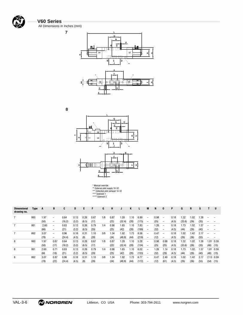
V60 Series
VAL-3-6 Littleton, CO USA Phone: 303-794-2611 www.norgren.com
1 0
5
14
1
4 2
3
0 1
12 SH
L
K
A
F
E
D G
Q
N
R
J
P
C*
**
*
M5
12
14
*****
****
4 2
5 1 3
L
SR
K
T
P
Q
J
A
C
G
E
D
U
N O
F H
***
B
*
**
77
88
7 V60 1.97 – 0.64 0.13 0.26 0.67 1/8 0.87 1.28 1.10 6.89 – 0.98 – 0.18 1.32 1.02 1.38 – –(50) – (16.2) (3.2) (6.5) (17) (22) (32.4) (28) (175) – (25) – (4.5) (33.6) (26) (35) – –
7 V61 2.60 – 0.83 0.13 0.26 0.79 1/4 0.98 1.65 1.10 7.83 – 1.26 – 0.18 1.73 1.02 1.57 – –(66) – (21) (3.2) (6.5) (20) (25) (42) (28) (199) – (32) – (4.5) (44) (26) (40) – –
7 V62 3.07 – 0.96 0.18 0.31 1.10 3/8 1.34 1.92 1.73 8.58 – 0.47 – 0.18 1.02 1.42 2.17 – –(78) – (24.4) (4.5) (8) (28) (34) (48.8) (44) (218) – (12) – (4.5) (26) (36) (55) – –
8 V60 1.97 0.67 0.64 0.13 0.26 0.67 1/8 0.87 1.28 1.10 5.28 – 0.98 0.98 0.18 1.32 1.02 1.38 1.81 0.59(50) (17) (16.2) (3.2) (6.5) (17) (22) (32.4) (28) (134) – (25) (25) (4.5) (33.6) (26) (35) (46) (15)
8 V61 2.60 0.71 0.83 0.13 0.26 0.79 1/4 0.98 1.65 1.10 6.02 – 1.26 1.14 0.18 1.73 1.02 1.57 1.81 0.59(66 (18) (21) (3.2) (6.5) (20) (25) (42) (28) (153) – (32) (29) (4.5) (44) (26) (40) (46) (15)
8 V62 3.07 0.87 0.96 0.18 0.31 1.10 3/8 1.34 1.92 1.73 6.77 – 0.47 2.40 0.18 1.02 1.42 2.17 2.13 0.59(78) (22) (24.4) (4.5) (8) (28) (34) (48.8) (44) (172) – (12) (61) (4.5) (26) (36) (55) (54) (15)
* Manual override** External pilot supply 10-32*** Collected pilot exhaust 10-32**** Solenoid 1***** Solenoid 2
A B C D E F G H J K L M N O P Q R S T UDimensionaldrawing no.
Type
All Dimensions in Inches (mm)

V60 Series
Littleton, CO USA Phone: 303-794-2611 www.norgren.com VAL-3-7
5/2 Solenoid Pilot Valves
14 4 2 12
5 1 3
Symbol Model Port size
Pilot exhaust
Pilot supply
Solenoidvariant
Flow Cv(l/min)
Operatingpressure (bar)
Pilot pressure(bar)
Dimensionaldrawing no.
lbs(kg)
1 (+) 12 (Solenoid 2)
2 (–) 12 + 14
3 (+) 14 (Solenoid 1)
123
Double solenoid DIN EN 175 301-803 (DIN 43650 type C) 4 pin
Coil & voltage codes
Secondary
24 V d.c. 13 A 2 W
VVoollttaaggee Coil code Power inrush/hold
SSyymmbbooll Plug no. Function Actuation
12 V d.c. 12J 2 W 54469-01
24 V d.c. 13J 2 W 54469-02
24 V 50/60 Hz 14J 4/2.5 VA 54469-04
48 V 50/60 Hz 16J 4/2.5 VA 54469-07
110/120 V 50/60 Hz 18J 4/2.5 VA 54469-03
220/240 V 50/60 Hz 19J 6/5 VA 54469-08
VVoollttaaggee Coil code Power inrush/hold Model
Voltage tolerance: ±10%
Rating: 100% E.D.
Protection class: IP 65 with sealed plugs (ISO 6952)
Electrical details
Plug configuration, valve side/twin pilot
Primary (22 mm coil industrial standard)
3-Pin Industrial Standard 22mmA = no connectorB = Cable grip 0-240Vac/Vdc 54934-01C = 6 ft molded cable, 0-240Vac/Vdc 54934-21H = Cable grip w/indicator light 24Vdc 54934-08J = Cable grip w/indicator light 120Vac 54934-02Z = 1/2" Conduit 0-240Vac/Vdc 54934-055 = 6 ft molded cable w/indicator light, surge suppression, 24Vac/Vdc 54934-306 = 6 ft molded cable w/indicator light, 120Vac 54934-35
4-Pin ConnectorA = no connectorY = 4–pin cable grip 0-240Vac/Vdc 0588666X = 4–pin 10’ molded cable 0-240Vac/Vdc 0102144
Connectors
**** Insert coil connector code from tables below. For manual override options, substitute ‘x’ as follows: 1 = without manual override
2 = locking
V60P517A-Ax**** 1/8 Internal Not collected Primary 0.75 (750) 29 to 116 (2 to 8) – 0.53 (0.24) 9 V60P527A-Ax**** 1/8 External Not collected Primary 0.75 (750) 26" Hg to 116 (-0.9 to 8) 44 to 116 (3 to 8) 0.53 (0.24) 9 V60P517D-Cx13AA 1/8 Internal Collected Secondary 0.75 (750) 29 to 145 (2 to 10) – 0.51 (0.23) 11V60P5223-Cx13AA 1/8 External Collected Secondary 0.75 (750) 26" Hg to 145 (-0.9 to 10) 44 to 145 (3 to 10) 0.51 (0.23) 11 V61R517A-Ax**** 1/4 Internal Not collected Primary 1.30 (1300) 29 to 116 (2 to 8) – 0.73 (0.33) 9 V61R527A-Ax**** 1/4 External Not collected Primary 1.30 (1300) 26" Hg to 116 (-0.9 to 8) 44 to 116 (3 to 8) 0.73 (0.33) 9 V61R517D-Cx13AA 1/4 Internal Collected Secondary 1.30 (1300) 29 to 145 (2 to 10) – 0.71 (0.32) 11 V62S517A-Ax**** 3/8 Internal Not collected Primary 2.60 (2600) 29 to 116 (2 to 8) – 1.36 (0.62) 9 V62S527A-Ax**** 3/8 External Not collected Primary 2.60 (2600) 26" Hg to 116 (-0.9 to 8) 44 to 116 (3 to 8) 1.36 (0.62) 9 V62S517D-Cx13AA 3/8 Internal Collected Secondary 2.60 (2600) 29 to 145 (2 to 10) – 1.34 (0.61) 11 V62S527D-Cx13AA 3/8 External Collected Secondary 2.60 (2600) 26" Hg to 145 (-0.9 to 10) 44 to 145 (3 to 10) 1.34 (0.61) 11 V60P511A-Ax**** 1/8 Internal Not collected Primary 0.75 (750) 29 to 116 (2 to 8) – 0.73 (0.33) 10 V60P522A-Ax**** 1/8 External Not collected Primary 0.75 (750) 26" Hg to 116 (-0.9 to 8) 44 to 116 (3 to 8) 0.51 (0.23) 11 V60P522D-Cx13AA 1/8 External Collected Secondary 0.75 (750) 26" Hg to 145 (-0.9 to 10) 44 to 145 (3 to 10) 0.51 (0.23) 11 V61R511A-Ax**** 1/4 Internal Not collected Primary 1.30 (1300) 29 to 116 (2 to 8) – 0.93 (0.42) 10 V61R522A-Ax**** 1/4 External Not collected Primary 1.30 (1300) 26" Hg to 116 (-0.9 to 8) 44 to 116 (3 to 8) 0.93 (0.42) 10 V61R511D-Cx13AA 1/4 Internal Collected Secondary 1.30 (1300) 29 to 145 (2 to 10) – 0.71 (0.32) 11 V61R522D-Cx13AA 1/4 External Collected Secondary 1.30 (1300) 26" Hg to 145 (-0.9 to 10) 44 to 145 (3 to 10) 0.71 (0.32) 11 V62S511A-Ax**** 3/8 Internal Not collected Primary 2.60 (2600) 29 to 116 (2 to 8) – 1.59 (0.72) 10 V62S522A-Ax**** 3/8 External Not collected Primary 2.60 (2600) 26" Hg to 116 (-0.9 to 8) 44 to 116 (3 to 8) 1.59 (0.72) 10 V62S511D-Cx13AA 3/8 Internal Collected Secondary 2.60 (2600) 29 to 145 (2 to 10) – 1.36 (0.62) 11 V62S522D-Cx13AA 3/8 External Collected Secondary 2.60 (2600) 26" Hg to 145 (-0.9 to 10) 44 to 145 (3 to 10) 1.36 (0.62) 11
14 4 212
5 1 3

V60 Series
VAL-3-8 Littleton, CO USA Phone: 303-794-2611 www.norgren.com
1 0
5
14
1
4 2
3
SH
MK
A
F
E
D G
Q
N
O
R
J
P
C
B
*
**
M5
1 0
14
5
4
0 1
1
2
3
12
C
J
N
Q
G
F
A
L
D
E
K
H
R S
P
*
**
*
M5
12
14
*****
****
4 2
5 1 3
L
SR
K
T
P
Q
J
A
C
G
E
D
U
N O
F H
*****
B
*
99 1100
1111
* Manual override** External pilot supply 10-32*** Collected pilot exhaust 10-32**** Solenoid 1***** Solenoid 2
A B C D E F G H J K L M N O P Q R S T UDimensionaldrawing no.
Type
9 V60 1.97 0.67 0.64 0.13 0.26 0.67 1/8 0.87 1.28 1.10 – 5.08 0.98 0.98 0.18 1.32 1.02 1.38 – –(50) (17) (16.2) (3.2) (6.5 (17) (22) (32.4) (28) – (129) (25) (25) (4.5) (33.6) (26) (35) – –
9 V6 2.60 0.71 0.83 0.13 0.26 0.79 1/4 0.98 1.65 1.10 – 5.91 1.26 1.14 0.18 1.73 1.02 1.57 – –(66) (18) (21) (3.2) (6.5 (20) (25) (42) (28) – (150) (32) (29) (4.5) (44) (26) (40) – –
9 V62 3.07 0.83 0.96 0.18 0.31 1.10 3/8 1.34 1.92 1.73 – 6.69 0.47 2.36 0.18 1.02 1.42 2.17 – –(78) (21) (24.4) (4.5) (8 (28) (34) (48.8) (44) – (170) (12) (60) (4.5) (26) (36) (55) – –
10 V60 1.97 – 0.64 0.13 0.26 0.67 1/8 0.87 1.28 1.10 6.89 – 0.98 – 0.18 1.32 1.02 1.38 – –(50) – (16.2) (3.2) (6.5 (17) (22) (32.4) (28) (175) – (25) – (4.5) (33.6) (26) (35) – –
10 V61 2.60 – 0.83 0.13 0.26 0.79 1/4 0.98 1.65 1.10 7.83 – 1.26 – 0.18 1.73 1.02 1.57 – –(66) – (21) (3.2) (6.5 (20) (25) (42) (28) (199) – (32) – (4.5) (44) (26) (40) – –
10 V62 3.07 – 0.96 0.18 0.31 1.10 3/8 1.34 1.92 1.73 8.58 – 0.47 – 0.18 1.02 1.42 2.17 – –(78) – (24.4) (4.5) (8 (28) (34) (48.8) (44) (218) – (12) – (4.5) (26) (36) (55) – –
11 V60 1.97 0.67 0.64 0.13 0.26 0.67 1/8 0.87 1.28 1.10 5.28 – 0.98 0.98 0.18 1.32 1.02 1.38 1.81 0.59(50) (17) (16.2) (3.2) (6.5 (17) (22) (32.4) (28) (134) – (25) (25) (4.5) (33.6) (26) (35) (46) (15)
11 V61 2.60 0.71 0.83 0.13 0.26 0.79 1/4 0.98 1.65 1.10 6.02 – 1.26 1.14 0.18 1.73 1.02 1.57 1.81 0.59(66) (18) (21) (3.2) (6.5 (20) (25) (42) (28) (153) – (32) (29) (4.5) (44) (26) (40) (46) (15)
11 V62 3.07 0.87 0.96 0.18 0.31 1.10 3/8 1.34 1.92 1.73 6.77 – 0.47 2.40 0.18 1.02 1.42 2.17 2.13 0.59(78) (22) (24.4) (4.5) (8 (28) (34) (48.8) (44) (172) – (12) (61) (4.5) (26) (36) (55) (54) (15)
All Dimensions in Inches (mm)

V60 Series
VAL-3-9
5/3 Solenoid Pilot Valves
144 2
12
5 1 3
144 2
12
5 1 3
144 2
12
5 1 3
Symbol Model Port size
Pilot exhaust
Pilot supply
Solenoidvariant
Flow Cv(l/min)
Operatingpressure (bar)
Pilot pressure(bar)
lbs(kg)
Dimensionaldrawing no.
1 (+) 12 (Solenoid 2)
2 (–) 12 + 14
3 (+) 14 (Solenoid 1)
123
Coil & voltage codesSSyymmbbooll Plug no. Function Actuation
12 V d.c. 12J 2 W 54469-01
24 V d.c. 13J 2 W 54469-02
24 V 50/60 Hz 14J 4/2,5 VA 54469-04
48 V 50/60 Hz 16J 4/2,5 VA 54469-07
110/120 V 50/60 Hz 18J 4/2,5 VA 54469-03
220/240 V 50/60 Hz 19J 6/5 VA 54469-08
VVoollttaaggee Coil code Power inrush/hold Model
Plug configuration, valve side/twin pilot
V60P611A-Ax**** 1/8 Internal Not collected Primary 0.50 (500) 44 to 116 (3 to 8) – 0.77 (0.35) 14
V60P622A-Ax**** 1/8 External Not collected Primary 0.50 (500) 26" Hg to 116 (-0.9 to 8) 44 to 116 (3 to 8) 0.77 (0.35) 14
V60P611D-Cx13AA 1/8 Internal Collected Secondary 0.50 (500) 44 to 145 (3 to 10) – 0.55 (0.25) 15
V60P622D-Cx13AA 1/8 External Collected Secondary 0.50 (500) 26" Hg to 145 (-0.9 to 10) 44 to 145 (3 to 10) 0.55 (0.25) 15
V61R611A-Ax**** 1/4 Internal Not collected Primary 0.95 (950) 44 to 116 (3 to 8) – 1.04 (0.47) 14
V61R622A-Ax**** 1/4 External Not collected Primary 0.95 (950) 26" Hg to 116 (-0.9 to 8) 44 to 116 (3 to 8) 1.04 (0.47) 14
V61R611D-Cx13AA 1/4 Internal Collected Secondary 0.95 (950) 44 to 145 (3 to 10) – 0.82 (0.37) 15
V61R622D-Cx13AA 1/4 External Collected Secondary 0.95 (950) 26" Hg to 145 (-0.9 to 10) 44 to 145 (3 to 10) 0.82 (0.37) 15
V62S611A-Ax**** 3/8 Internal Not collected Primary 1.90 (1900) 44 to 116 (3 to 8) – 1.79 (0.81) 14
V62S622A-Ax**** 3/8 External Not collected Primary 1.90 (1900) 26" Hg to 116 (-0.9 to 8) 44 to 116 (3 to 8) 1.79 (0.81) 14
V62S611D-Cx13AA 3/8 Internal Collected Secondary 1.90 (1900) 44 to 116 (3 to 8) 44 to 145 (3 to 10) 1.57 (0.71) 15
V62S622D-Cx13AA 3/8 External Collected Secondary 1.90 (1900) 26" Hg to 145 (-0.9 to 10) 44 to 145 (3 to 10) 1.57 (0.71) 15
V60P711A-Ax**** 1/8 Internal Not collected Primary 0.50 (500) 44 to 116 (3 to 8) – 0.77 (0.35) 14
V60P722A-Ax**** 1/8 External Not collected Primary 0.50 (500) 26" Hg to 116 (-0.9 to 8) 44 to 116 (3 to 8) 0.77 (0.35) 14
V60P711D-Cx13AA 1/8 Internal Collected Secondary 0.50 (500) 44 to 145 (3 to 10) – 0.55 (0.25) 15
V60P722D-Cx13AA 1/8 External Collected Secondary 0.50 (500) 26" Hg to 145 (-0.9 to 10) 44 to 145 (3 to 10) 0.55 (0.25) 15
V61R711A-Ax**** 1/4 Internal Not collected Primary 0.95 (950) 44 to 116 (3 to 8) – 1.04 (0.47) 14
V61R722A-Ax**** 1/4 External Not collected Primary 0.95 (950) 26" Hg to 116 (-0.9 to 8) 44 to 116 (3 to 8) 1.04 (0.47) 14
V61R711D-Cx13AA 1/4 Internal Collected Secondary 0.95 (950) 44 to 145 (3 to 10) – 0.82 (0.37) 15
V61R722D-Cx13AA 1/4 External Collected Secondary 0.95 (950) 26" Hg to 145 (-0.9 to 10) 44 to 145 (3 to 10) 0.82 (0.37) 15
V62S711A-Ax**** 3/8 Internal Not collected Primary 1.90 (1900) 44 to 116 (3 to 8) – 1.79 (0.81) 14
V62S722A-Ax**** 3/8 External Not collected Primary 1.90 (1900) 26" Hg to 116 (-0.9 to 8) 44 to 116 (3 to 8) 1.79 (0.81) 14
V62S711D-Cx13AA 3/8 Internal Collected Secondary 1.90 (1900) 44 to 145 (3 to 10) – 1.57 (0.71) 15
V62S722D-Cx13AA 3/8 External Collected Secondary 1.90 (1900) 26" Hg to 145 (-0.9 to 10) 44 to 145 (3 to 10) 1.57 (0.71) 15
V60P811A-Ax**** 1/8 Internal Not collected Primary 0.50 (500) 44 to 116 (3 to 8) – 0.77 (0.35) 14
V60P822A-Ax**** 1/8 External Not collected Primary 0.50 (500) 26" Hg to 116 (-0.9 to 8) 44 to 116 (3 to 8) 0.77 (0.35) 14
V60P811D-Cx13AA 1/8 Internal Collected Secondary 0.50 (500) 44 to 145 (3 to 10) – 0.55 (0.25) 15
V60P822D-Cx13AA 1/8 External Collected Secondary 0.50 (500) 26" Hg to 145 (-0.9 to 10) 44 to 145 (3 to 10) 0.55 (0.25) 15
V61R811A-Ax**** 1/4 Internal Not collected Primary 0.95 (950) 44 to 116 (3 to 8) – 1.04 (0.47) 14
V61R822A-Ax**** 1/4 External Not collected Primary 0.95 (950) 26" Hg to 116 (-0.9 to 8) 44 to 116 (3 to 8) 1.04 (0.47) 14
V61R811D-Cx13AA 1/4 Internal Collected Secondary 0.95 (950) 44 to 145 (3 to 10) – 0.82 (0.37) 15
V61R822D-Cx13AA 1/4 External Collected Secondary 0.95 (950) 26" Hg to 145 (-0.9 to 10) 44 to 145 (3 to 10) 0.82 (0.37) 15
V62S811A-Ax**** 3/8 Internal Not collected Primary 1.90 (1900) 44 to 116 (3 to 8) – 1.79 (0.81) 14
V62S822A-Ax**** 3/8 External Not collected Primary 1.90 (1900) 26" Hg to 116 (-0.9 to 8) 44 to 116 (3 to 8) 1.79 (0.81) 14
V62S811D-Cx13AA 3/8 Internal Collected Secondary 1.90 (1900) 44 to 145 (3 to 10) – 1.57 (0.71) 15
V62S822D-Cx13AA 3/8 External Collected Secondary 1.90 (1900) 26" Hg to 145 (-0.9 to 10) 44 to 145 (3 to 10) 1.57 (0.71) 15
Primary (22 mm coil industrial standard)
3-Pin Industrial Standard 22mmA = no connectorB = Cable grip 0-240Vac/Vdc 54934-01C = 6 ft molded cable, 0-240Vac/Vdc 54934-21H = Cable grip w/indicator light 24Vdc 54934-08J = Cable grip w/indicator light 120Vac 54934-02Z = 1/2" Conduit 0-240Vac/Vdc 54934-055 = 6 ft molded cable w/indicator light, surge suppression, 24Vac/Vdc 54934-306 = 6 ft molded cable w/indicator light, 120Vac 54934-35
4-Pin ConnectorA = no connectorY = 4–pin cable grip 0-240Vac/Vdc 0588666X = 4–pin 10’ molded cable 0-240Vac/Vdc 0102144
Double solenoid DIN EN 175 301-803 (DIN 43650 type C) 4 pinSecondary
24 V d.c. 13 A 2 W
VVoollttaaggee Coil code Power inrush/hold
Voltage tolerance: ±10%
Rating: 100% E.D.
Protection class: IP 65 with sealed plugs (ISO 6952)
Electrical details
Connectors
Littleton, CO USA Phone: 303-794-2611 www.norgren.com
**** Insert coil connector code from tables below. For manual override options, substitute ‘x’ as follows: 1 = without manual override APB = All ports blocked
2 = locking COE = Center open exhaust3 = non-locking COP = Center open pressure
APB
COE
COP
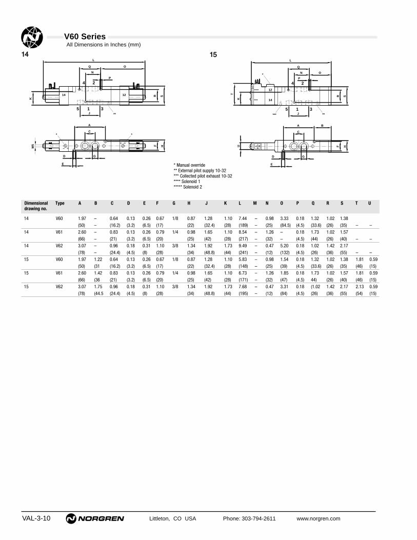
V60 Series
VAL-3-10 Littleton, CO USA Phone: 303-794-2611 www.norgren.com
1 0
5
14
1
4 2
3
0 1
12 SH
L
K
A
F
E
D G
Q O
N
R
J
P
C*
**
*
M5
12
14
*****
****
4 2
5 1 3
L
SR
K
T
P
Q
J
A
C
G
E
D
U
N O
F H
*****
B
*
1144 1155
14 V60 1.97 – 0.64 0.13 0.26 0.67 1/8 0.87 1.28 1.10 7.44 – 0.98 3.33 0.18 1.32 1.02 1.38(50) – (16.2) (3.2) (6.5) (17) (22) (32.4) (28) (189) – (25) (84.5) (4.5) (33.6) (26) (35) – –
14 V61 2.60 – 0.83 0.13 0.26 0.79 1/4 0.98 1.65 1.10 8.54 – 1.26 – 0.18 1.73 1.02 1.57(66) – (21) (3.2) (6.5) (20) (25) (42) (28) (217) – (32) – (4.5) (44) (26) (40) – –
14 V62 3.07 – 0.96 0.18 0.31 1.10 3/8 1.34 1.92 1.73 9.49 – 0.47 5.20 0.18 1.02 1.42 2.17(78) – (24.4) (4.5) (8) (28) (34) (48.8) (44) (241) – (12) (132) (4.5) (26) (36) (55) – –
15 V60 1.97 1.22 0.64 0.13 0.26 0.67 1/8 0.87 1.28 1.10 5.83 – 0.98 1.54 0.18 1.32 1.02 1.38 1.81 0.59(50) (31 (16.2) (3.2) (6.5) (17) (22) (32.4) (28) (148) – (25) (39) (4.5) (33.6) (26) (35) (46) (15)
15 V61 2.60 1.42 0.83 0.13 0.26 0.79 1/4 0.98 1.65 1.10 6.73 – 1.26 1.85 0.18 1.73 1.02 1.57 1.81 0.59(66) (36 (21) (3.2) (6.5) (20) (25) (42) (28) (171) – (32) (47) (4.5) 44) (26) (40) (46) (15)
15 V62 3.07 1.75 0.96 0.18 0.31 1.10 3/8 1.34 1.92 1.73 7.68 – 0.47 3.31 0.18 (1.02 1.42 2.17 2.13 0.59(78) (44.5 (24.4) (4.5) (8) (28) (34) (48.8) (44) (195) – (12) (84) (4.5) (26) (36) (55) (54) (15)
* Manual override** External pilot supply 10-32*** Collected pilot exhaust 10-32**** Solenoid 1***** Solenoid 2
A B C D E F G H J K L M N O P Q R S T UDimensionaldrawing no.
Type
All Dimensions in Inches (mm)

V60 Series
Littleton, CO USA Phone: 303-794-2611 www.norgren.com VAL-3-11
V60P4D7A-X5090 1/8 Air Spring 0.75 (750) 26" Hg to 145 (-0.9 to 10) 36 to 145 (2.5 to 10) 0.29 (0.13) 16
V61R4D7A-X5090 1/4 Air Spring 1.30 (1300) 26" Hg to 145 (-0.9 to 10) 36 to 145 (2.5 to 10) 0.46 (0.21) 16
V62S4D7A-X5090 3/8 Air Spring 2.60 (2600) 26" Hg to 145 (-0.9 to 10) 36 to 145 (2.5 to 10) 0.95 (0.43) 16
V60P3D7A-X5090 1/8 Spring Air 0.75 (750) 26" Hg to 145 (-0.9 to 10) 36 to 145 (2.5 to 10) 0.29 (0.13) 17
V61R3D7A-X5090 1/4 Spring Air 1.30 (1300) 26" Hg to 145 (-0.9 to 10) 36 to 145 (2.5 to 10) 0.46 (0.21) 17
V62S3D7A-X5090 3/8 Spring Air 2.60 (2600) 26" Hg to 145 (-0.9 to 10) 36 to 145 (2.5 to 10) 0.95 (0.43) 17
V60P4DDA-X5020 1/8 Air Air 0.75 (750) 26" Hg to 145 (-0.9 to 10) 22 to 145 (1.5 to 10) 0.29 (0.13) 18
V61R4DDA-X5020 1/4 Air Air 1.30 (1300) 26" Hg to 145 (-0.9 to 10) 22 to 145 (1.5 to 10) 0.46 (0.21) 18
V62S4DDA-X5020 3/8 Air Air 2.60 (2600) 26" Hg to 145 (-0.9 to 10) 22 to 145 (1.5 to 10) 0.95 (0.43) 18
V60PADDA-X5020 1/8 Air Air 0.50 (500) 29 to 145 (2 to 10) 29 to 145 (2 to 10) 0.40 (0.18) 19
V61RADDA-X5020 1/4 Air Air 0.95 (950) 29 to 145 (2 to 10) 29 to 145 (2 to 10) 0.67 (0.28) 19
V62SADDA-X5020 3/8 Air Air 1.90 (1900) 29 to 145 (2 to 10) 29 to 145 (2 to 10) 1.32 (0.60) 19
V60PCDDA-X5020 1/8 Air Air 0.50 (500) 29 to 145 (2 to 10) 29 to 145 (2 to 10) 0.40 (0.18) 19
V61RCDDA-X5020 1/4 Air Air 0.95 (950) 29 to 145 (2 to 10) 29 to 145 (2 to 10) 0.67 (0.28) 19
V62SCDDA-X5020 3/8 Air Air 1.90 (1900) 29 to 145 (2 to 10) 29 to 145 (2 to 10) 1.32 (0.60) 19
V60PBDDA-X5020 1/8 Air Air 0.50 (500) 29 to 145 (2 to 10) 29 to 145 (2 to 10) 0.40 (0.18) 19
V61RBDDA-X5020 1/4 Air Air 0.95 (950) 29 to 145 (2 to 10) 29 to 145 (2 to 10) 0.67 (0.28) 19
V62SBDDA-X5020 3/8 Air Air 1.90 (1900) 29 to 145 (2 to 10) 29 to 145 (2 to 10) 1.32 (0.60) 19
3/2 Air Pilot Valves
2 x 3/2 Air Pilot Valves
144 10
5 1
10 212
3
51
10
3
104 14 12 2
104 14
51
10 212
3
NC/NC
NO/NO
NO/NC
NC/NC = Both valves normally closedNO/NO = Both valves normally openNO/NC = 1 valve normally open, 1 valve normally closed
NC = Normally closed, NO = Normally open
122
10
3 1
102
12
1 3
122
10
3 1
NO
Symbol Model Port size Operator12
Operator10
Flow Cv(l/min)
Operating pressure psi (bar)
Pilot pressurepsi (bar)
lbs(kg)
Dimensionaldrawing no.
Symbol Model Port size Operator14
Operator12
Flow Cv(l/min)
Operating pressurepsi (bar)
Pilot pressurepsi (bar)
lbs(kg)
Dimensionaldrawing no.
Symbol Model Port size Operator10
Operator10
Flow Cv(l/min)
Operating pressurepsi (bar)
Pilot pressure(bar)
lbs(kg)
Dimensionaldrawing no.
Symbol Model Port size Operator10
Operator12
Flow Cv(l/min)
Operating pressurepsi (bar)
Pilot pressure(bar)
lbs(kg)
Dimensionaldrawing no.
NC

V60 Series
VAL-3-12 Littleton, CO USA Phone: 303-794-2611 www.norgren.com
13
2
12
A B
G
D
E
F H
J
R
M
N
P
Q
O
S
K
T
U
1 3
2
10
P
Q
N
O
M
R S
J
K
H
A
G
F
D
E
U
T B
12
1 3
2
10
L
K
BA
F
G
E
D
H
O
P
R
N
J
Q
S
T
U1166 1177
1188
5
14
31
4 2
12K
L
T BA
G
F
E
D
C
H
P
O
R
N
J
Q
S
U
1199
16 V60 1.38 1.14 – 0.13 0.26 0.67 1/8 0.87 0.64 1.10 – 3.39 0.98 1.46 0.18 0.71 1.02 1.38 0.67 1/8" NPT(35) (29) – (3.2) (6.5) (17) (22) (16.2) (28) – (86) (25) (37) (4.5) (18) (26) (35) (17)
16 V61 1.81 1.38 – 0.13 0.26 0.79 1/4 0.98 0.83 1.10 – 4.13 1.26 1.81 0.18 0.94 1.02 1.57 0.71 1/8" NPT(46) (35) – (3.2) (6.5) (20) (25) (21) (28) – (105) (32) (46) (4.5) (24) (26) (40) (18)
16 V62 2.13 1.69 – 0.18 0.31 1.10 3/8 1.34 0.96 1.73 – 4.88 0.47 2.28 0.18 1.02 1.42 2.17 0.83 1/8" NPT(54) (43) – (4.5) (8) (28) (34) (24.4) (44) – (124) (12) (58) (4.5) (26) (36) (55) (21)
17 V60 1.38 1.14 – 0.13 0.26 0.67 1/8 0.87 0.64 1.10 – 3.39 0.98 1.46 0.18 0.71 1.02 1.38 0.67 1/8" NPT(35) (29) – (3.2) (6.5) (17) (22) (16.2) (28) – (86) (25) (37) (4.5) (18) (26) (35) (17)
17 V61 1.81 1.38 – 0.13 0.26 0.79 1/4 0.98 0.83 1.10 – 4.13 1.26 1.81 0.18 0.94 1.02 1.57 0.71 1/8" NPT(46) (35) – (3.2) (6.5) (20) (25) (21) (28) – (105) (32) (46) (4.5) (24) (26) (40) (18)
17 V62 2.13 1.69 – 0.18 0.31 1.10 3/8 1.34 0.96 1.73 – 4.88 0.47 2.20 0.18 1.02 1.42 2.17 0.83 1/8" NPT(54) (43) – (4.5) (8) (28) (34) (24.4) (44) – (124) (12) (56) (4.5) (26) (36) (55) (21)
18 V60 1.38 0.91 – 0.13 0.26 0.67 1/8 0.87 0.64 1.10 3.15 – 0.98 1.22 0.18 0.71 1.02 1.38 0.67 1/8" NPT(35) (23) – (3.2) (6.5) (17) (22) (16.2) (28) (80) – (25) (31) (4.5) (18) (26) (35) (17)
18 V61 1.81 0.94 – 0.13 0.26 0.79 1/4 0.98 0.83 1.10 3.70 – 1.26 1.38 0.18 0.94 1.02 1.57 0.71 1/8" NPT(46) (24) – (3.2) (6.5) (20) (25) (21) (28) (94) – (32) (35) (4.5) (24) (26) (40) (18)
18 V62 2.13 1.06 – 0.18 0.31 1.10 3/8 1.34 0.96 1.73 4.25 – 0.47 1.65 0.18 1.02 1.42 2.17 0.83 1/8" NPT(54) (27) – (4.5) (8) (28) (34) (24.4) (44) (108) – (12) (42) (4.5) (26) (36) (55) (21)
19 V60 1.97 0.91 0.64 0.13 0.26 0.67 1/8 0.87 1.28 1.10 3.74 – 0.98 1.22 0.18 1.32 1.02 1.38 0.67 1/8" NPT(50) (23) (16.2) (3.2) (6.5) (17) (22) (32.4) (28) (95) – (25) (31) (4.5) (33.6) (26) (35) (17)
19 V61 2.60 0.94 0.83 0.13 0.26 0.79 1/4 0.98 1.65 1.10 4.49 – 1.26 1.38 0.18 1.73 1.02 1.57 0.71 1/8" NPT(66) (24) (21) (3.2) (6.5) (20) (25) (42) (28) (114) – (32) (35) (4.5) (44) (26) (40) (18)
19 V62 3.07 1.06 0.96 0.18 0.31 1.10 3/8 1.34 1.92 1.73 5.20 – 0.47 2.60 0.18 1.02 1.42 2.17 0.83 1/8" NPT(78) (27) (24.4) (4.5) (8) (28) (34) (48.8) (44) (132) – (12) (66) (4.5) (26) (36) (55) (21)
A B C D E F G H J K L M N O P Q R S T UDimensionaldrawing no.
Type
All Dimensions in Inches (mm)

V60 Series
Littleton, CO USA Phone: 303-794-2611 www.norgren.com VAL-3-13
5/2 Air Pilot ValvesSymbol Model Port size Operator
12Operator10
Flow Cv(l/min)
Operating pressurepsi (bar)
Pilot pressurepsi (bar)
lbs(kg)
Dimensionaldrawing no.
5/3 Air Pilot Valves
V60P5D7A-X5090 1/8 Air Spring 0.75 (750) 26" Hg to 145 (-0.9 to 10) 36 to 145 (2.5 to 10) 0.35 (0.16) 22
V61R5D7A-X5090 1/4 Air Spring 1.30 (1300) 26" Hg to 145 (-0.9 to 10) 36 to 145 (2.5 to 10) 0.57 (0.26) 22
V62S5D7A-X5090 3/8 Air Spring 2.60 (2600) 26" Hg to 145 (-0.9 to 10) 36 to 145 (2.5 to 10) 1.23 (0.56) 22
V60P5DDA-X5020 1/8 Air Air 0.75 (750) 26" Hg to 145 (-0.9 to 10) 36 to 145 (2.5 to 10) 0.37 (0.17) 23
V61R5DDA-X5020 1/4 Air Air 1.30 (1300) 26" Hg to 145 (-0.9 to 10) 36 to 145 (2.5 to 10) 0.60 (0.27) 23
V62S5DDA-X5020 3/8 Air Air 2.60 (2600) 26" Hg to 145 (-0.9 to 10) 36 to 145 (2.5 to 10) 1.28 (0.58) 23
Symbol Model Port size Operator14
Operator12
Flow Cv(l/min)
Operating pressure psi (bar)
Pilot pressurepsi (bar)
lbs(kg)
Dimensionaldrawing no.
V60P6DDA-X5020 1/8 Air Air 0.50 (500) 26" Hg to 145 (-0.9 to 10) 44 to 145 (3 to 10) 0.44 (0.2) 24
V61R6DDA-X5020 1/4 Air Air 0.95 (950) 26" Hg to 145 (-0.9 to 10) 44 to 145 (3 to 10) 0.71 (0.32) 24
V62S6DDA-X5020 3/8 Air Air 1.90 (1900) 26" Hg to 145 (-0.9 to 10) 44 to 145 (3 to 10) 1.48 (0.67) 24
V60P7DDA-X5020 1/8 Air Air 0.50 (500) 26" Hg to 145 (-0.9 to 10) 44 to 145 (3 to 10) 0.44 (0.2) 24
V61R7DDA-X5020 1/4 Air Air 0.95 (950) 26" Hg to 145 (-0.9 to 10) 44 to 145 (3 to 10) 0.71 (0.32) 24
V62S7DDA-X5020 3/8 Air Air 1.90 (1900) 26" Hg to 145 (-0.9 to 10) 44 to 145 (3 to 10) 1.48 (0.67) 24
V60P8DDA-X5020 1/8 Air Air 0.50 (500) 26" Hg to 145 (-0.9 to 10) 44 to 145 (3 to 10) 0.44 (0.2) 24
V61R8DDA-X5020 1/4 Air Air 0.95 (950) 26" Hg to 145 (-0.9 to 10) 44 to 145 (3 to 10) 0.71 (0.32) 24
V62S8DDA-X5020 3/8 Air Air 1.90 (1900) 26" Hg to 145 (-0.9 to 10) 44 to 145 (3 to 10) 1.48 (0.67) 24
142
12
5 1 3
144 2
12
5 1 3
14
4 2
12
5 1 3
14
4 2
12
5 1 3
14
4 2
12
5 1 3
APB
COE
COP
APB = All Ports Blocked,COE = Center Open ExhaustCOP = Center Open Pressure

V60 Series
VAL-3-14 Littleton, CO USA Phone: 303-794-2611 www.norgren.com
14
5 1
4
3
2
M
O
SR
B
HF
T
K
E
DU
A
C
G
P
Q
J
N
14
5 1
4
3
2
12
Q
N O
L
R
HF
B
D
E
T
KU
C
A
G
J
P
S
5
14
31
4 2
12K
L
T BA
G
F
E
D
C
H
P
O
R
N
J
Q
S
U2222 2233
2244
22 V60 1.97 1.14 0.64 0.13 0.26 0.67 1/8 0.87 1.28 1.10 – 3.98 0.98 1.46 0.18 1.73 1.02 1.38 0.67 1/8" NPT(50) (29) (16.2) (3.2) (6.5) (17) (22) (32.4) (28) – (101) (25) (37) (4.5) (44) (26) (35) (17)
22 V61 2.60 1.38 0.83 0.13 0.26 0.79 1/4 0.98 1.65 1.10 – 4.92 1.26 1.38 0.18 1.02 1.02 1.57 0.71 1/8" NPT(66) (35) (21) (3.2) (6.5) (20) (25) (42) (28) – (125) (32) (35) (4.5) (26) (26) (40) (18)
22 V62 3.07 1.69 0.96 0.18 0.31 1.10 3/8 1.34 1.92 1.73 – 5.83 0.47 3.23 0.18 1.32 1.42 2.17 0.83 1/8" NPT(78) (43) (24.4) (4.5) (8) (28) (34) (48.8) (44) – (148) (12) (82) (4.5) (33.6) (36) (55) (21)
23 V60 1.97 0.91 0.64 0.13 0.26 0.67 1/8 0.87 1.28 1.10 3.74 – 0.98 1.(22) 0.18 1.73 1.02 1.38 0.67 1/8" NPT(50) (23) (16.2) (3.2) (6.5) (17) (22) (32.4) (28) (95) – (25) (31) (4.5) (44) (26) (35) (17)
23 V61 2.60 0.94 0.83 0.13 0.26 0.79 1/4 0.98 1.65 1.10 4.49 – 1.26 1.38 0.18 1.02 1.02 1.57 0.71 1/8" NPT(66) (24) (21) (3.2) (6.5) (20) (25) (42) (28) (114) – (32) (35) (4.5) (26) (26) (40) (18)
23 V62 3.07 1.06 0.96 0.18 0.31 1.10 3/8 1.34 1.92 1.73 5.20 – 0.47 2.60 0.18 1.32 1.42 2.17 0.83 1/8" NPT(78) (27) (24.4) (4.5) (8) (28) (34) (48.8) (44) (132) – (12) (66) (4.5) (33.6) (36) (55) (21)
24 V60 1.97 1.46 0.64 0.13 0.26 0.67 1/8 0.87 1.28 1.10 4.29 – 0.98 1.77 0.18 1.73 1.02 1.38 0.67 1/8" NPT(50) (37) (16.2) (3.2) (6.5) (17) (22) (32.4) (28) (109) – (25) (45) (4.5) (44) (26) (35) (17)
24 V61 2.60 1.85 0.83 0.13 0.26 0.79 1/4 0.98 1.65 1.10 5.39 – 1.26 2.28 0.18 1.02 1.02 1.57 0.71 1/8" NPT(66) (47) (21) (3.2) (6.5) (20) (25) (42) (28) (137) – (32) (58) (4.5) (26v (26) (40) (18)
24 V62 3.07 1.95 0.96 0.18 0.31 1.10 3/8 1.34 1.92 1.73 6.08 – 0.47 3.48 0.18 1.32 1.42 2.17 0.83 1/8" NPT(78) (49.5) (24.4) (4.5) (8) (28) (34) (48.8) (44) (154.5) – (12) (88.5) (4.5) (33.6) (36) (55) (21)
A B C D E F G H J K L M N O P Q R S T UDimensionaldrawing no.
Type
All Dimensions in Inches (mm)

V60 Series
Littleton, CO USA Phone: 303-794-2611 www.norgren.com VAL-3-15
Manifold plate 2 stations + 3 stations
Manifold systemManifold plate
G
F E
AB
C
D
J K N
M
H
U
R
O P
T L
2 2221032 0.51 (0.23)3 2221033 0.62 (0.28)
2221132 0.62 (0.28) 2221133 0.99 (0.45)
2221232 1.10 (0.50)2221233 1.87 (0.85)
V60 V61 V62Valve portsModel
lbs(kg) Model
lbs (kg) Model
lbs(kg)
Drawing dimensions
V60 2 stations 1.93 3.86 1.18 0.63 0.31 0.43 0.83 1.26 0.43 1.40 1.81 1/8 1/4 0.24 3.39 1.10 – 0.91 for(49) (98) (30) (16) (8) (11) (21) (32) (11) (35.5) (46) (6) (86) (28) – (23) 10-32
V60 3 stations 1.93 3.86 1.18 0.63 0.31 0.43 0.83 1.26 0.43 1.40 2.72 1/8 1/4 0.24 3.39 1.10 – 0.91 for(49) (98) (30) (16) (8) (11) (21) (32) (11) (35.5) (69) (6) (86) (28) – (23) 10-32
V61 2 stations 2.05 4.09 1.02 0.35 0.31 0.51 0.83 1.30 0.39 1.40 2.05 1/8 3/8 1.57 0.94 1.02 – 1.02 for(52) (104) (26) (9) (8) (13) (21) (33) (10) (35.5) (52) (40) (24) (26) – (26) 10-32
V61 3 stations 2.05 4.09 1.02 0.35 0.31 0.51 0.79 1.30 0.39 1.40 3.07 1/8 3/8 1.57 0.94 2.05 – 1.02 for(52) (104) (26) (9) (8) (13) (20) (33) (10) (35.5) (78) (40) (24) (52) – (26) 10-32
V62 2 stations 2.36 4.72 1.14 0.35 0.31 0.59 0.87 1.50 0.51 1.40 2.76 1/8 1/2 1.73 1.26 1.38 – 1.38(60) (120) (29) (9) (8) (15) (22) (38) (13) (35.5) (70) (44) (32) (35) – (35) for M6
V62 3 stations 2.36 4.72 1.14 0.35 0.31 0.59 0.87 1.50 0.51 1.40 4.13 1/8 1/2 1.73 1.26 2.76 – 1.38(60) (120) (29) (9) (8) (15) (22) (38) (13) (35.5) (105) (44) (32) (70) – (35) for M6
A B C D E F G H J K L M N O P R S T UType
All Dimensions in Inches (mm)
0101796 (V60V62) 0.02 lbs (0.01 kg)
DIN Rail fixing kit
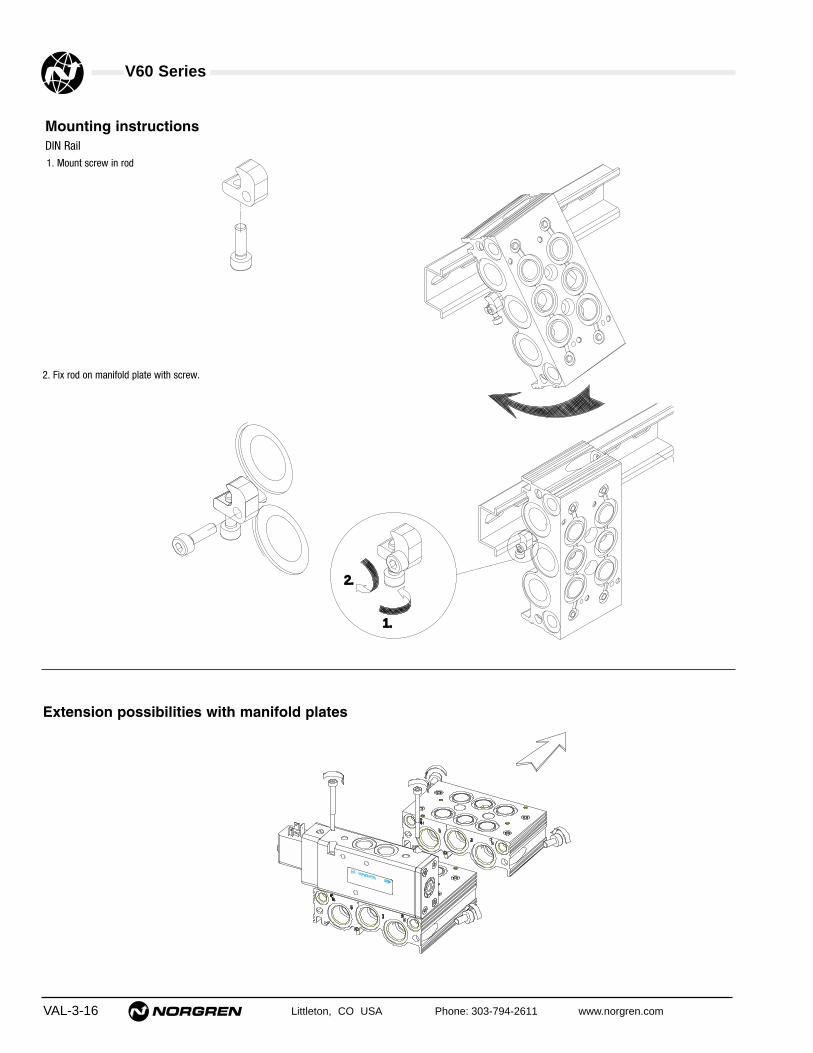
V60 Series
VAL-3-16 Littleton, CO USA Phone: 303-794-2611 www.norgren.com
Mounting instructionsDIN Rail1. Mount screw in rod
1.1.
2.2.
2. Fix rod on manifold plate with screw.
Extension possibilities with manifold plates

V60 Series
Littleton, CO USA Phone: 303-794-2611 www.norgren.com VAL-3-17
1 = no override2 = locking3 = non-locking
V60 V61 V62
A = 1/8" ISO GP = 1/8" NPT
B = 1/4" ISO GR = 1/4" NPT
C = 3/8" ISO GS = 3/8" NPT
3 = 3/2 NO4 = 3/2 NC5 = 5/26 = 5/3 APB7 = 5/3 COE8 = 5/3 COPA = 2 x 3/2 NC, NCB = 2 x 3/2 NO, NOC = 2 x 3/2 NO, NC
1 = Solenoid Pilot, internal2 = Solenoid Pilot, externalD = Air Pilot
1 = Solenoid Pilot, internal2 = Solenoid Pilot, external3 = Air Spring Return7 = Spring ReturnD = Air Pilot
AA = Standard Solenoid DC = Twin Pilot Solenoid AX = Air Pilot
1 = no override2 = locking3 = non-locking
5 = M5 air pilot portsP = 1/8" NPT
12J = 12 Vdc 16J = 48 Vac13J = 24 Vdc 18J = 120 Vac14J = 24 Vac 19J = 240 Vac
13A = 24 Vdc twin pilot 020 = double air pilot090 = single air pilot
Blank = no connectorB = Cable grip 0-240 Vac/VdcC = 6 ft molded cable, 0-240 Vac/VdcH = Cable grip w/indicator light 24VdcJ = Cable grip w/indicator light 120VacZ = 1/2" Conduit 0-240 Vac/Vdc5 = 6 ft molded cable w/indicator light,
surge suppression, 24Vac/Vdc6 = 6 ft molded cable w/indicator light,
surge suppression, 120Vac
A = no connectorY = 4–pin cable grip 0-240Vac/VdcX = 4–pin molded cable 0-240Vac/Vdc
V 6 0 A 5 1 7 A – A 3 1 3 J B

Littleton, CO USA Phone: 303-794-2611 www.norgren.com VAL-4-1
Section 4
Norgren Mini ISO Star Series Directional Control ValvesAvailable with V40/V44 Glandless Technology, or V41/V45 Softseal technology, the Mini ISO Star is an excellent choicefor high and low pressure applications where a long lasting mini valve is required. With fast response times, extremelylow leak rates, and competitive pricing, this valve will provide years of reliable service.
Mini ISO Star Series Valves
Compact, high performance pneumaticvalves with a comprehensive range of
subbases and accessoriesContentsFeatures and Benefits . . . . . . . . . . . . . . . . . . . . . . . . .VAL-4-2Specifications and Technical Data (18 mm) . . . . . . . .VAL-4-4Bases and Accessories (18 mm) . . . . . . . . . . . . . . . .VAL-4-7Valve Dimensions (18 mm) . . . . . . . . . . . . . . . . . . . . .VAL-4-8External to Internal Pilot Conversion (18 mm) . . . . . .VAL-4-9Manifold Ordering Information (18 mm) . . . . . . . . . .VAL-4-10Subbase Dimensions (18 mm) . . . . . . . . . . . . . . . . .VAL-4-11Specifications and Technical Data (26 mm) . . . . . . .VAL-4-18Bases and Accessories (26 mm) . . . . . . . . . . . . . . .VAL-4-21Valve Dimensions (26 mm) . . . . . . . . . . . . . . . . . . . .VAL-4-22External to Internal Pilot Conversion (26 mm) . . . . .VAL-4-23Manifold Ordering Information (26 mm) . . . . . . . . . .VAL-4-24Subbase Dimensions (26 mm) . . . . . . . . . . . . . . . . .VAL-4-25Valve Numbering System . . . . . . . . . . . . . . . . . . . . .VAL-4-30
Compact 18 mm and 26 mm width Single and Double sandwich
pressure regulators available
Sandwich flow control
End ported 1/4" NPTor ISO G (18 mm), 3/8"NPT or ISO G (26 mm)
Modular Subbases availableside ported, 1/8, 1/4 NPTF, G1/4, 3/8" PIF, with or withoutpilot ports.

VAL-4-2 Littleton, CO USA Phone: 303-794-2611 www.norgren.com
Mini ISO Star Series Valves
End Plate KitEnd ported1/4" or 3/8" NPTF or ISO G
Single Valve Shut-Off Plate Sandwich Flow Control
Single Station SubbaseSide ported, 1/8, or 1/4 NPTF or ISO Gwith pilot ports
Modular SubbaseSide ported, 1/8 or 1/4 NPTF, or ISO G with or without pilot ports
Modular SubbaseSide ported, 1/4" or 3/8" PIFwith or without pilot ports
Mini ISO Star Valve System
Flexible subbase system witha wide range of accessories
• International standard
• Compact design and highperformance
• Comprehensive range of subbases and accessories
• The right spool technology for critical pneumaticapplications
• Low power solenoid (1.2 W)and collected pilot exhaust
• Easily converted frominternal to external pilotsupply
• 18 mm and 26 mm widths
• A variety of valve functionsand voltages
Single (Port 1,2 or 4)and Double (Ports 2 and 4)Sandwich Pressure Regulator
Intermediate Supply/Exhaust Module

Littleton, CO USA Phone: 303-794-2611 www.norgren.com VAL-4-3
Mini ISO Star Series Valves
5/2 and 5/3 valve functions
Air spring return Mechanical spring return
Impulse All ports blocked
Center open exhaust Center open pressure
Dual 3-way
Technical/Electrical detailsV40/V44 Glandless valve V41/V45 Softseal valve
Operation: Solenoid pilot or air pilot Solenoid pilot or air pilotOperating pressure: max. 230 psig max.150 psigFlow: Cv of 0.62 (18 mm) Cv of 0.69 (18 mm)
0.9 (26 mm) 1.2 (26 mm)Pilot pressure: min.15 psig min. 30 psig
Solenoid pilot valveVoltage tolerances: -10% / +15%Rating: 100% continuous dutyInlet orifice: 0.8 mmManual override: Push button, spring return (non lockable)
Convertible into push & turn type (lockable) with Set-up Kit part no. V70532-K00
Electrical connection: DIN 43650 table ‘C’Protection class: IP 65, NEMA 4
Medium compressed air, filtered, lubricated or non-lubricated
Voltage variety
• Non-corrosive, Nituff®* coated,precision matched aluminum spool and sleeve
• High and low pressure applications
• Cv of 0.58 (18 mm),and 0.9 (26 mm)
• Minimum 100 million cycles* Nituff is a finishing process producing a hard
anodized coating of low friction teflon type polymers.
V40/V44 GlandlessTechnology
• High flow Cv of 0.66 (18 mm), 1.2 (26 mm)
• Fast response
• Minimum 50 million cycles
• Extremely low leakage rates
• Two 3/2 normally closed or normally openvalves in one 5/2 body
• Competitively priced
V41/V45 Softseal Technology
Multi pressure system
5 184 823
4 210 1014 12
Solenoid pilot air valves are available with internalpilot supply and collected pilot exhaust, or externalpilot supply with non-collected exhaust

VAL-4-4 Littleton, CO USA Phone: 303-794-2611 www.norgren.com
V40 / V41 Series Mini ISO Valves
● Compact design and high performance
● Flexible Sub-base system
● True multipressure system
● Sandwich regulators and flow controls
● Dual spool technologyV40 Glandless spool and sleeveV41 Softseal spool
● Collected pilot exhaust with internal pilot air supply
● Easy to convert from internal to external pilot supply
● Exchange of valves under pressure
2x3/2, 5/2 and 5/3 Valves Solenoid and Pilot ActuatedISO 15407-1 / VDMA 24 563 Size 18 mm
Technical DataMedium:
Compressed air, 40µm filtered, lubricated or non-lubricatedOperation:
V40: Glandless spool valve, solenoid pilot or air pilot actuatedV41: Softseal spool valve, solenoid pilot or air pilot actuated
Mounting:On sub-bases
Size:ISO 15407/-1 / VDMA 24 563, 18 mm
Operating Pressure:Maximum pressure 145 psig (10 bar) V41 models and V40 solenoid pilot actuated
valves with internal pilot supply232 psig (16 bar) V40 solenoid pilot actuated valves w. ext.
pilot supply and V40 air pilot actuated valvesDetails of minimum and maximum pilot pressure see overleaf
Flow Characteristics:Series Function Cv ‘C’ ‘b’ ‘A’ l/min KvV40 5/2 0.58 2.39 0.19 9.14 570 0.50V40 5/3 0.62 2.39 0.31 9.88 610 0.53V41* 2x3/2 0.62 2.49 0.24 9.83 610 0.53V41* 5/2 0.66 2.65 0.24 10.46 650 0.57V41* 5/3 0.69 2.63 0.33 11.04 680 0.59
Ambient Temperature:5°F* to +122°F (-15°C* to +50°C) V40/V41 sol. and V41 air pilot models5°F* to +176°F (-15°C* to +80°C) V40 air pilot models*Consult our Technical Service for use below 36° F ( +2°C)
Materials:Aluminum alloy body and sub-base. Hard anodized, Tefloncoated, matched aluminum spool and sleeve(V40) or aluminumalloy spool with HNBR Seals (V41). POM plastic parts and NBRstatic seals. End cover and screws zinc plated, stainless steelsprings.
14 125 1 3243 1214 5 4 1 2
V40 V41
5/2
2 x 3/2 Dual 3-way
5/3 APBAll ports blocked mid position
5/3 COECentre open exhaustmid position
5/3 COPCentre open pressuremid position
Ordering Information
To order select model number, add voltagecode from table on page VAL-4-5,e.g. V415517D-C313Afor a 5/2 solenoid pilot actuated, spring returnmodel, 24 V DC pilot.
5 184 823
4 210 1014 12

Littleton, CO USA Phone: 303-794-2611 www.norgren.com VAL-4-5
Mini ISO Star Series 18 mm Valves
Symbol Model Spool Pilot Pilot Operator Return Flow Operating Pressure Pilot Pressure Weight Repair KitTechn. Supply Exhaust 14 12 Cv psig (bar) psig (bar) lb. (kg)
V405513D-C3**† Gl Internal Collected x Solenoid Air Spring 0.5814.5–145
–0.26
V70440-K5O(1–10) (0.12)
V415513D-C3**† Ss Internal Collected x Solenoid Air Spring 0.6614.5–145
–0.29
V70442–K50(1–10) (0.13)
V405523D-C3**† Gl External Not collected Solenoid Air Spring 0.5826" Hg–232 14.5–145 0.26
V70440-K5O(-0.9–16) (1–10) (0.12)
V415523D-C3**† Ss External Not collected Solenoid Air Spring 0.6626" Hg–145 14.5–145 0.29
V70442–K50(-0.9–10) (1–10) (0.13)
V405516D-C3**† Gl Internal Collected x Solenoid Spring & Air 0.5823.2–145
–0.29
V70440-K5O(1.6–10) (0.13)
V415517D-C3**† Ss Internal Collected x Solenoid Spring 0.6629–145
–0.29
V70442-K5O(2–10) (0.13)
V405526D-C3**† Gl External Not collected Solenoid Spring & Air 0.5826" Hg–232 23.2–145 0.29
V70440-K5O(-0.9–16) (1.6–10) (0.13)
V415527D-C3**† Ss External Not collected Solenoid Spring 0.6626" Hg–145 29–145 0.29
V70442-K5O(-0.9–10) (2–10) (0.13)
V405511D-C3**† Gl Internal Collected x Solenoid Solenoid 0.5829–145
–0.40
V70441-K5O(2–10) (0.18)
V415511D-C3**† Ss Internal Collected x Solenoid Solenoid 0.6629–145
–0.40
V70443-K5O(2–10) (0.18)
V405522D-C3**† Gl External Not collected Solenoid Solenoid 0.5826" Hg–232 29–145 0.40
V70441-K5O(-0.9–16) (2–10) (0.18)
V415522D-C3**† Ss External Not collected Solenoid Solenoid 0.6626" Hg–145 29–145 0.40
V70443-K5O(-0.9–10) (2–10) (0.18)
V405591D-C3**† Gl Internal Collected xSolenoid
Solenoid 0.5829–145
–0.40
V70441-K5O(Priority) (2–10) (0.18)
V405592D-C3**† Gl External Not collectedSolenoid
Solenoid 0.5826" Hg–232 29–145 0.40
V70441-K5O(Priority) (-0.9–16) (2–10) (0.18)
4 214 12
351
84
4 214
351
84
12
4 214 12
351
84 82
4 214 12
1435
18284
4 21412
1435
1
84
4 214 12
35114
84
5/2 Solenoid Pilot Actuated Valves
4 214 12
351
84 82
4 214 12
12/1435
184 82
General Information
Symbol Model Function Pilot Pilot Actuation Flow Operating Pressure Pilot Pressure Weight Repair Kit2x3/2 Supply Exhaust 3/2 Function Cv psig (bar) psig (bar) lb. (kg)
V415A11D-C3**†Normally
Internal Collected x Sol/Spring 0.6236–145
–0.40
V70447-K5OClosed (2.5–10) (0.18)
V415A22D-C3**†Normally
External Not Collected Sol/Spring 0.620–145 24.7+(0.35xop.press.) 0.40
V70447-K5OClosed (0–10) [1.7 + (0.35 x op. press.)] (0.18)
V415B11D-C3**†Normally
Internal Collected x Sol/Spring 0.6236–145
–0.40
V70448-K5OOpen (2.5–10) ()0.18
V415B22D-C3**†Normally
External Not Collected Sol/Spring 0.620–145 24.7 + (0.35 x op. press.) 0.40
V70448-K5OOpen (0–10) [1.7+(0.35xop.press.)] (0.18)
V415C11D-C3**†Norm.Open/
Internal Collected x Sol/Spring0.62 36–145
–0.40
V70449-K5ONorm. Closed 0.62 (2.5–10) (0.18)
V415C22D-C3**†Norm.Open/
External Not collected Sol/Spring0.62 0–145 24.7+ (0.35 x op. press.) 0.40
V70449-K5ONorm. Closed 0.62 (0–10) [(1.7+(0.35xop.press.)] (0.18)
2x3/2 Solenoid Pilot Actuated Valves (Softseal Spool only)
5 184 823
4 210 1014 12
84 823
4 214 1210 10
5 184
1482
3
4 210 1014 12
8410
823
4 214 1210 10
5 184 823
4 210 1214 10
5 184 82
3
4 210 1214 10
10
Electrical Details for Solenoid PilotVoltage Tolerances -10% / +15%
Rating 100% Continuous Duty
Inlet orifice 0.8 mm
Electrical Connection DIN 43 650 table 'C'
Manual Override Shrouded push button, spring returnConvertible into lockable type with Set-up Kit Part no. V70532-K00 (see page VAL-4-7)
Protection Class IP 65 with sealed plug (ISO 6952)NEMA 4
Materials PPS (body), Viton and NBR (seals)
**Voltage Codes and Spare Pilot ValvesVoltage Code Power Inrush / Hold Pilot Valve Part.-no.
12 V d.c. 12 1 W VZC7L2C1-C312A
24 V d.c. 13 1.2 W VZC7L2C1-C313A
24 V 50/60 Hz. 14 2.1 / 1.5 VA VZC7L2C1-C314A
48 V 50/60 Hz 16 2.1 / 1.5 VA VZC7L2C1-C316A
110 V d.c. 17 1 W VZC7L2C1-C317A
115 V 50/60 Hz 18 2.1 / 1.5 VA VZC7L2C1-C318A
230 V 50/60 Hz 19 2.1 / 1.5 VA VZC7L2C1-C319AOther voltages available on request. Spare pilot valves are delivered with mounting screws.
Connector Codes and Part NumberCode Part Number
A = Solenoid without connector
B = Cable grip V10027-D00
C = 10 ft. molded cable, 0-240 VAC/VDC V10013-D03
H = Cable grip w/indicator light, 24 VAC/VDC V10012-D13
J = Cable grip w/indicator light, 120 VAC/VDC V10012-D18
5 = 10 ft. molded cable with indicator light, surge suppression, 24 VAC/VDC V10014-D03
6 = 10 ft. molded cable with indicator light, 110V/50 Hz-120V.60Hz V10015-D03
** Insert ‘Voltage Code’ from table ‘Voltage Codes and Spare Pilot Valves’ below.† Add connector code from table below.x Pilot Exhaust collected and exhausted via port 14
Spool Technology Designations:Gl = Glandless Spool and SleeveSs = Softseal Spool
Valve Function Designations: APB = All Ports BlockedCOE = Center Open ExhaustCOP = Center Open Pressure

VAL-4-6 Littleton, CO USA Phone: 303-794-2611 www.norgren.com
Mini ISO Star Series 18 mm Valves
Symbol Model Spool Operator Return Flow Operating Pressure Pilot Pressure Weight Repair KitTechn. 14 12 Cv psig (bar) psig (bar) lb. (kg)
V405537A-X0090 Gl Air Spring 0.5826" Hg–232 23.2–232 0.24
V70440-K5O(-0.9–16) (1.6–16) (0.11)
V415537A-X0090 Ss Air Spring 0.6626" Hg–145 29–145 0.22
V70442-K5O(-0.9–10) (2–10) (0.10)
V405533A-X0020 Gl Air Air 0.5826" Hg–232 29–232 0.24
V70441-K5O(-0.9–16) (2–16) (0.11)
V415533A-X0020 Ss Air Air 0.6626" Hg–145 29–145 0.24
V70443-K5O(-0.9–10) (2–10) (0.11)
V405533A-X0070 GlAir
Air 0.5826" Hg–232 29–232 0.24
V70441-K5O(Priority) (-0.9–16) (2–16) (0.11)
5/2 Air Pilot Actuated Valves
4 214 12
351
4 214 12
351
Symbol Model Spool Valve Function Operator Return Flow Operating Pressure Pilot Pressure Weight Spares KitTechn. 14 12 Cv psig (bar) psig (bar) lb. (kg)
V405633A-X0020 Gl APB Air Air 0.6226" Hg–232 29–232 0.24
V70441-K5O(-0.9–16) (2–16) (0.11)
V415633A-X0020 Ss APB Air Air 0.6926" Hg–145 29–145 0.26
V70444-K5O(-0.9–10) (2–10) (0.12)
V405733A-X0020 Gl COE Air Air 0.6226" Hg–232 29–232 0.24
V70441-K5O(-0.9–16) (2–16) (0.11)
V415733A-X0020 Ss COE Air Air 0.6926" Hg–145 29–145 0.26
V70445-K5O(-0.9–10) (2–10) (0.12)
V405833A-X0020 Gl COP Air Air 0.6226" Hg–232 29–232 0.24
V70441-K5O(-0.9–16) (2–16) (0.11)
V415833A-X0020 Ss COP Air Air 0.6926" Hg–145 29–145 0.26
V70446-K5O(-0.9–10) (2–10) (0.12)
5/3 Air Pilot Actuated Valves
4 21214
351
4 21214
351
4 21214
351
4 214 12
351
Symbol Model Function 2x3/2 Actuation Flow Operating Pressure Pilot Pressure Weight Repair Kit3/2 Function Cv psig (bar) psig (bar) lb. (kg)
V415A33A-X0020 Normally Closed Air/Spring 0.620–145 24.7 + (0.35 x op. pressure) 0.26
V70447-K5O(0–10) (1.7 + (0.35 x op. pressure)) (0.12)
V415B33A-X0020 Normally Open Air/Spring 0.620–145 24.7 + (0.35 x op. pressure) 0.26
V70448-K5O(0–10) (1.7 + (0.35 x op. pressure)) (0.12)
V415C33A-X0020Normally Open/
Air/Spring0.62 0–145 24.7 + (0.35 x op. pressure) 0.26
V70449-K5ONormally Closed 0.62 (0–10) (1.7 + (0.35 x op. pressure)) (0.12)
2x3/2 Air Pilot Actuated Valves (Softseal Spool only)
5 1 3
4 210 12
1014
5 1 3
4 210 10
1214
5 1 3
4 214 12
1010
5/3 Solenoid Pilot Actuated ValvesSymbol Model Spool Valve Pilot Pilot Operator Return Flow Operating Pressure Pilot Pressure Weight Repair Kit
Techn. Function Supply Exhaust 14 12 Cv psig (bar) psig (bar) lb. (kg)
V405611D-C3**† Gl APB Internal Collected x Solenoid Solenoid 0.6229–145
–0.40
V70441-K5O(2–10) (0.18)
V415611D-C3**† Ss APB Internal Collected x Solenoid Solenoid 0.6929–145
–0.40
V70444-K5O(2–10) (0.18)
V405622D-C3**† Gl APB External Not collected Solenoid Solenoid 0.6226" Hg–232 29–145 0.40
V70441-K5O(-0.9–16) (2–10) (0.18)
V415622D-C3**† Ss APB External Not collected Solenoid Solenoid 0.6926" Hg–145 29–145 0.40
V70444-K5O(-0.9–10) (2–10) (0.18)
V405711D-C3**† Gl COE Internal Collected x Solenoid Solenoid 0.6229–145
–0.40
V70441-K5O(2–10) (0.18)
V415711D-C3**† Ss COE Internal Collected x Solenoid Solenoid 0.6929–145
–0.40
V70445-K5O(2–10) (0.18)
V405722D-C3**† Gl COE External Not collected Solenoid Solenoid 0.6226" Hg–232 29–145 0.40
V70441-K5O(-0.9–16) (2–10) (0.18)
V415722D-C3**† Ss COE External Not collected Solenoid Solenoid 0.6926" Hg–145 29–145 0.40
V70445-K5O(-0.9–10) (2–10) (0.18)
V405811D-C3**† Gl COP Internal Collected x Solenoid Solenoid 0.6229–145
–0.40
V70441-K5O(2–10) (0.18)
V415811D-C3**† Ss COP Internal Collected x Solenoid Solenoid 0.6929–145
–0.40
V70446-K5O(2–10) (0.18)
V405822D-C3**† Gl COP External Not collected Solenoid Solenoid 0.6226" Hg–232 29–145 0.40
V70441-K5O(-0.9–16) (2–10) (0.18)
V415822D-C3**† Ss COP External Not collected Solenoid Solenoid 0.6926" Hg–145 29–145 0.40
V70446-K5O(-0.9–10) (2–10) (0.18)
4 2 1214
351
84 82
4 2 1214
351
84 82
4 2 1214
351
84 82
4 2 1214
1435
184 82
4 2 1214
1435
184 82
4 2 1214
1435
184 82
** Insert ‘Voltage Code’ from table ‘Voltage Codes and Spare Pilot Valves’ on page VAL-4-5† Add connector code from page VAL-4-5x Pilot Exhaust collected and exhausted via port 14
Spool Technology Designations:Gl = Glandless Spool and SleeveSs = Softseal Spool
Valve Function Designations: APB = All Ports BlockedCOE = Center Open ExhaustCOP = Center Open Pressure

Littleton, CO USA Phone: 303-794-2611 www.norgren.com VAL-4-7
Mini ISO Star Series 18 mm Valves
Single Station Sub-base Modular Sub-base Modular Sub-base Modular Sub-base Modular Sub-baseSide Ported with Pilot Ports Side Ported without Pilot Ports Side Ported with Pilot Ports Side Ported (PIF) without Pilot Ports Side Ported (PIF) with Pilot Ports
V70401-P5B (1/8NPTF) V70425-P5F (1/8NPTF) V70426-P5F (1/8NPTF) V70425-15F (ø1/4”) V70426-15F (ø1/4”)
V70401-A5B (G1/8) V70425-A5F (G1/8) V70426-A5F (G1/8) V70425-85F (ø8 mm) V70426-85F (ø8 mm)
V70425-65F (ø6 mm) V70426-65F (ø6 mm)
End Plate Kit Double Station Modular Sub-base End Plate Kit with 2 Side Ported Fixed Length Sub-baseEnd Ported Side Ported without Pilot Ports Valve Stations without Pilot Ports Bottom Ported
V70424-R5C (1/4NPTF) V70432-P5F (1/8NPTF) V70431-P5F (1/4, 1/8NPTF) V704**-P50 (1/8NPTF)
V70424-B5C (G1/4) V70432-A5F (G1/8”) V70431-A5F (G1/4, G1/8) ** = 02,04,06,08,10,12 stations
Bases
Accessories
Sandwich Plate with additionalIntermediate Supply/Exhaust Module Single Valve Shut-Off Plate Pressure Port 1 Single Pressure Regulator Plate Double Pressure Regulator Plate
V70429-P5O (1/8NPTF) V70430-K5O (Port 1 open/closed) V70435-P50 (1/8NPTF) V70427-K51 (Port 1 reg.) V70427-K54 (Ports 2+4 reg.)
V70429-A5O (G1/8) V70427-K52 (Port 2 reg.)
V70427-K53 (Port 4 reg.)
Flow Regulator Plate Blanking Plate for unused Station DIN EN 50 022 rail (1 metre) DIN-rail Mounting Kit Blanking Disk to Modular Sub-base
V70428-K5O (Ports 3+5 reg.) V70400-K5O V10009-C00 (35x7.5mm) V70531-KA0 V70422-K50 (1 each) (Ports 1,3,5)
V10592-C01 (35x15mm) V70423-K50 (1 each) (Ports 12+14)
Blanking Plug for Manual Override Set-Up Kit Transition Plate #18 mm ➞ #26 mm* Transition Plate #18 mm ➞ #26 mm*
Fixed Length Sub-base V70532-K00 V70436-K00 V70436-R00 (1/4 NPTF)
V70421-K50 (Ports 1,3,5) V70436-B00 (G1/4)
Bases and Accessories

Mini ISO Star Series 18 mm ValvesAll Dimensions in Inches (mm)
VAL-4-8 Littleton, CO USA Phone: 303-794-2611 www.norgren.com
V4055*3D-C3*** and V4155*3D-C3*** Models5/2 Single Solenoid Pilot ValveAir Spring Return
1.63 (41.3)
3.89 (98.9)
M3
0.73
(18
.6)
3.04
(77
.2)
1.18
(29
.9)
0.20
(5)
0.49
(12
.5)
Manual Override
1.63 (41.3)
3.89 (98.9)
M3
0.73
(18
.6)
3.04
(77
.2)
1.18
(29
.9)
0.20
(5)
0.49
(12
.5)
Manual Override
V4055*6D-C3*** and V4155*7D-C3*** Models5/2 Single Solenoid Pilot ValveMechanical (& Air) Spring Return
V4055**D-C3*** and V4155**D-C3*** Models5/2 Double Solenoid Pilot Valve
4.53 (115.2)
8.6)
2.5)
2.
Manual Override
3.76 (95.6)
3.04
(77
.2)
1.18
(29
.9)
0.20
(5)
M3
4.53 (115.2)
8.6)
2.5)
2.
Manual Override
3.76 (95.6)
3.04
(77
.2)
1.18
(29
.9)
0.20
(5)
M3
V405***D-C3*** and V415***D-C3*** Models2x3/2 + 5/3 Double Solenoid Pilot Valve
V415537A-X00905/2 Single Air Pilot Valve
0.49
(12
.5)
0.73
(18
.6)
1.63 (41.3)
3.89 (98.9)
1.37
(34
.8)
1.18
(29
.9)
0.20
(5) M3
V405537A-X0090 5/2 Single Air Pilot ValveV405*33A-X00*0 and V415*33A-X00*0 Models2x3/2, 5/2 + 5/3 Double Air Pilot Valve
0.73
(18
.6)
1.37
(34
.8)
4.53 (115.2)
2.27 (57.6)
M3
1.18
(29
.9)
0.20
(5) 2.
5)

Littleton, CO USA Phone: 303-794-2611 www.norgren.com VAL-4-9
Mini ISO Star Series 18 mm Valves
Conversion from internal to external pilot supply / Collected pilot exhaust
The lowered and captive gasket between valve body and pilot valve defines and indicates pilot air supply as well as pilotexhaust function of the valve.
INTEXT
INTEXT
INTEXT
Internal pilot supply,pilot exhaust air collected and exhausted via port 14.
All solenoid pilot valves with code 1 at position 6 in the part number (e.g V41551...) have the gasket mounted in this position on delivery.
External pilot supply from port 14 only,pilot exhaust air not collected but bleed through valve body.
All solenoid pilot valves with code 2 at position 6 in thepart number (e.g V41552...) have the gasket mountedin this position on delivery.
blue gasketblue gasket
Note: Dismounting pilot valve gives access to gasket. Conversion from internal to external pilot supply (or vice versa)by turning the gasket.Caution: In this case part number and symbol on label shows different function. Therefore check gasket positionwhen mounting valve.
Note: Additional to above described work, gasketbetween end cap and valve body must beturned too at valves with this function.For detailed instructions see Installation- andMaintenance Sheet.
Air pilot actuated valvesExternal pilot supply.
blue gasket
Drawing includescover plate.
Drawing showsno pilot valve.
Solenoid pilot actuated valves
Air pilot actuated valves 5/2 Solenoid pilot actuated valves with air spring returnDrawing shows end cap side 12.
INT
EXT
INT
EXT

VAL-4-10 Littleton, CO USA Phone: 303-794-2611 www.norgren.com
Mini ISO Star Series 18 mm Valves
Order a factory assembled manifold
V = Valve Product
41 = Mini ISO (Size 18 mm)
X = Default (No Wireway)
02 to 20 stations
XXX = Default
A = Side Ported, without Pilot PortsE = Side Ported, with Pilot Ports
XX = single pressure application01-19 = Number of stations for dual
pressure into manifold
P = 1/4" NPTF (1,3,5), 1/8" NPTF (2,4)A = G1/4 (1,3,5), G1/8 (2,4)1 = 1/4" NPTF (1,3,5), 1/4" PIF (2,4)8 = G1/4 (1,3,5), 8 mm PIF (2,4)6 = G1/4 (1,3,5), 6 mm PIF (2,4)
The following ordering example details the information needed to order a 4-valve, single solenoid, 24 VDC, cable grip electricalconnector, single pressure manifold.
One Mini ISO manifold consisting of:Position Quantity Part No.
1-4 4 V40A513D-C313B1 V41PAX04-XXXXX
V 4 1 P A X 0 7 - X X X X X
Ordering Example

Littleton, CO USA Phone: 303-794-2611 www.norgren.com VAL-4-11
Mini ISO Star Series 18 mm ValvesAll Dimensions in Inches (mm)
x/y = Insert port type from tablebelow
Individual components
Modular Sub-base 0.12 kgPorts 2+4 on side (0.26 lb)V70425-x5F
Double Station Modular Sub-base 0.24 kgPorts 2+4 on side (0.53 lb)V70432-y5F
Modular Sub-base 0.12 kgPorts 2+4 on side (0.26 lb)Pilot Ports 12+14 on sideV70426-x5F
End Plate Kit 0.21 kgEnd Ported (0.46 lb)V70424-B5C (G1/4)V70424-R5C (1/4NPTF)End ported end caps1 left hand and 1 right hand
End Plate Kit with Valve StationPorts 2+4 on side 0.4 kgV70431-A5F (0.88 lb)(1/3/5 G1/4, 2/4 G1/8)V70431-P5F (1/3/5 1/4NPTF, 2/4 1/8NPTF)End ported end caps1 left hand and 1 right hand
Accessories
DIN EN 50022 rail 0.31 kg35 x 7,5 mm, 1m (0.68 lb)V10009-C00
DIN EN 50022 rail 1.02 kg35 x 15 mm, 1m (2.25 lb)V10592-C01
DIN rail 0.01 kgMounting Kit (0.02 lb)V70531-KAO
Blanking Disk to 0.01 kgModular Sub-base (0.02 lb)Ports 1, 3, 5V70422-K50
Blanking Disk to 0.01 kgModular Sub-base (0.02 lb)Ports 12+14V70423-K50
A
Modular Sub-bases parts for DIN rail or surface mounting
A
C
D
Code x Code y Ports 2+4 Ports 12+14A A G1/8 M5P P 1/8NPTF M58 – ø 8 mm PIF M56 – ø 6 mm PIF M51 – ø 1/4” PIF M5
Bottom ported sub-base
Side ported sub-base
Bottom and side ported sub-base
Note:Port 14 either used for external pilot air supply or for collected pilot air exhaust.Therefore, never plug port 14 when using valves with internal pilot air supply.Port 12 is not used, plugging not necessary.
D
0.45
(11
.6)
CA C
0.18 (4.6)
12 12 12
222
4 4 4
M5
0.30
(7.
7)1.
07 (
27.2
)
1.52
(38
.6)
0.45 (11.4)
M5
Left Hand SideRight Hand Side
View Y
0.30 (7.6)
1.52
(38
.6)
1.34
(34
)
14 14 14
Ø 0.17 (Ø 4.3)
0.15 (3.8)
2.11 (53.5)0.30
(7.
5)
0.67
(17
)0.
67 (
17)
*N x
0.7
5 (1
9.1)
*N = Number of stations
0.54 (13.7)
1.85 (47)
1.24 (31.4)
0.37 (9.3)
0.59
(15
)
1.22
(31
)
1.11 (28.2)
1.68 (42.7)
14M5
Y
12
35
1
M5
2.56 (65)
1.30
(32
.9)
1.75
(44
.4)
0.14
(3.
5)
2.89
(73
.4) 4.
74 (
120.
4)

Mini ISO Star Series 18 mm ValvesAll Dimensions in Inches (mm)
VAL-4-12 Littleton, CO USA Phone: 303-794-2611 www.norgren.com
B
View X
0.37 (9.5)
6x1/4
NPTF
1/8
NPTF
0.18 (4.5)
X
Ø 0.31 (Ø
8)
Ø 0.18 (Ø 4.5)
0.22 (5.5)
0.87 (22)
0.75 (19.1)
0.81
(20
.6)
0.79
(20
)0.
83 (
21)
62.2
(2.
45)
0.85
(21
.5)
0.85
(21
.5)
L
51
3
2.60 (66)
2.28 (58)
1.18 (30)
1.97 (50)
0.30
(7.
5)
0.35
(9)
0.91
(23
)
0.43
(11
)
5 1 3
0.59 (15)
1.57 (40)
Ø 0.17 (Ø 4.3) 5xA
2x10-32 UNF
0.16
(4)
0.59
(15
)2.28 (58)Ø 0.17 (Ø 4.2)
2xM
3
0.49
(12
.5)
0.52
(13
.3)
1.04
(26
.5)
14 4 2 12
Model Port Size A Weightlb (kg)
V70401-P5B 1/8NPTFSide Ported with Pilot Ports 0.18
V70401-A5B G1/8 (0.08)Side Ported with Pilot Ports
Single Station Sub-base - Side Ported with Pilot Ports
Fixed Length Sub-base - Bottom Ported
Note: Pilot Ports for both types = 10-32 UNF
Model No. of A B WeightStations inch (mm) inch (mm) lb (kg)
V70402-P5O 2 2.33 1.89 0.40(59.1) (48.1) (0.18)
V70404-P5O 4 3.83 3.40 0.66(97.3) (86.3) ()0.30
V70406-P5O 6 5.34 4.90 0.93(135.5) (124.5) (0.42)
V70408-P5O 8 6.84 6.41 1.19(173.7) (162.7) (0.54)
V70410-P5O 10 8.34 7.91 1.46(211.9) (200.9) (0.66)
V70412-P5O 12 9.85 9.41 1.72(250.1) (239.1) (0.78)
Note: This sub-base is suitable for solenoidpilot actuated valves with internal pilot air supply only.

Mini ISO Star Series 18 mm ValvesAll Dimensions in Inches (mm)
Littleton, CO USA Phone: 303-794-2611 www.norgren.com VAL-4-13
Model Port Size A Weightlb (kg)
V70429-P5O 1/8NPTF 0.11V70429-A5O G1/8 (0.05)
Intermediate Supply / Exhaust Module
Model Description Weightlb (kg)
V70430-K5O Single Shut-Off Plate 0.13supplied with gasket (0.06)
Provides additional porting on Modular- orFixed Length Sub-base.Occupies one valve station.Supplied with gasket for both sub-bases.
1.77 (45)
M3
3 x A
0.91 (23)
1.22 (31)
0.73
(18
.6)
0.81
(20
.5)
0.22
(5.
5)0.
37 (
9.3)
0.42
(10
.6)
0.49
(12
.5)
2.20 (56)
0.31 (8)
3 1 5
Single Valve Shut-Off Plate
0.98 (25)
2.88 (73.2)
0.49
(12
.5)
0.73
(18
.6)
M3
0.67
(17
)
0.20
(5)
0.37 (9.3)
0.36
(9.
15)
Can be used to:- Improve supply flow- Increase exhaust capacity- Pneumatically separate valves for fail
save emergency- Multipressure system and system solutions
Allows individual exchange of valve, whilevalve island is pressurized by port 1.
Note: Flow restricted to maximum .24 Cv
14 2

Mini ISO Star Series 18 mm ValvesAll Dimensions in Inches (mm)
VAL-4-14 Littleton, CO USA Phone: 303-794-2611 www.norgren.com
Model Description Weightlb (kg)
V70428-K5O Flow Control 0.13supplied with gasket (0.06)
Model Description Weightlb (kg)
V70400-K5O Blanking Plate for 0.04blocking of unused Stations (0.02)(supplied with gasket)
Blanking Plate
M4
0.39
(10
)0.
24 (
6)0.
75 (
19)
1.02
(26
)
2.76 (70)
Sandwich Flow Control
1.50 (38)
0.24 (6.1)
0.61
(15
.5)
0.30
(7.
5)
0.20
(5)
2.99 (76)
M3
0.73
(18
.6)
0.49
(12
.5)
Dual Regulation of Exhaust Ports 3 and 5
00 1 2 3 4 5 6 7 8 9 10 11 12
.05
.10
.15
.20
.25
.30
.35
.40
.45
Flow: Port 1➨ 2 and 1➨ 4: remains unchangedFlow measured at 6 bar inlet, Pressure drop 1 bar
3 5
Number of turns from closed
Exh
aust
Flo
w
(Po
rts
3+5)
[C
v]

Mini ISO Star Series 18 mm ValvesAll Dimensions in Inches (mm)
Littleton, CO USA Phone: 303-794-2611 www.norgren.com VAL-4-15
Pressure Regulator Plates (including gauge and adapter tube)
M3
0.98 (25) 0.73 (18.6)
1.20
(30
.5)
0.49
(12
.5)
2.19
(55
.5) 3.36
(85
.4)
0.22
(5.
5)
3.86 (98)
5.47 (138.9)
M3
0.98 (25)
1.20
(30
.5)
0.49
(12
.5)
2.19
(55
.5)
3.36
(85
.4)
4.06 (103)
5.66 (143.9)
0.73 (18.6)
0.22
(5.
5)
Model Description Weight lb (kg)
V70427-K53 Regulation 0.46 of Port 4 (0.21)
Model Description Weight lb (kg)
V70427-K52 Regulation 0.46 of Port 2 (0.21)
Model Description Weight lb (kg)
V70427-K51 Regulation 0.46of Port 1 (0.21)
Maximum inlet pressure 232 psig(16 bar)
Regulated pressure 14.5–145 psig(1–10 bar)
Maximum inlet pressure 232 psig(16 bar)
Regulated pressure 14.5–145 psig(1–10 bar)
Maximum inlet pressure 232 psig(16 bar)
Regulated pressure 14.5–145 psig(1–10 bar)
M3
0.98 (25) 0.73 (18.6)
1.20
(30
.5)
0.49
(12
.5)
2.19
(55
.5) 3.36
(85
.4)
0.22
(5.
5)
3.86 (98)
5.47 (138.9)

Mini ISO Star Series 18 mm ValvesAll Dimensions in Inches (mm)
VAL-4-16 Littleton, CO USA Phone: 303-794-2611 www.norgren.com
Flow Characteristics forPressure Regulator Plates
0
(1.0)
(2.0)
(3.0)
(4.0)
(5.0)
(6.0)
(7.0)
0(50) (100) (150) (200) (250) (300) (350) (l/min)
Inlet presssure = 116 psig (8 bar)
Reg
ula
ted
pre
ssu
re
1.8 3.5 5.3 7.1 8.8 10.6 12.4 SCFM
14.5
29.2
43.5
58.0
72.5
89.0
101.5
PSIG(bar)
M3
1.61 (40.9) 2.87 (73)1.
20 (
30.5
)
0.49 (12.5)
2.19
(55
.5)
0.22
(5.
5)
3.36
(85
.4)
5.94 (151) 0.73 (18.6)
9.16 (232.7)
Model Description Weight lb (kg)
V70427-K54 Regulation 0.79 of Ports 2+4 (0.36)
Maximum inlet pressure 232 psig(16 bar)
Regulated pressure 14.5–145 psig(1–10 bar)

Mini ISO Star Series 18 mm ValvesAll Dimensions in Inches (mm)
Littleton, CO USA Phone: 303-794-2611 www.norgren.com VAL-4-17
0.98 (25)
2.24 (57)
M3 0.37 (9.3)
1/8 NPTF
0.61
(15
.5)
0.31
(8)
0.49
(12
.5)
0.22
(5.
5)
0.73
(18
.6)
Sandwich Plate with additional Pressure Port 1
Transition Plate #18 mm ➞ #26 mm
Model Description Weight lb (kg)
V70435-P5O Sandwich Plate 0.09with additional (0.04)Port 1, suppliedwith gasket
Model Description Port 1/3/5 Weight lb (kg)
V70436-K0O Transition Plate without Ports 1/3/5 0.71# 18 – # 26 mm (0.32)
V70436-R00 Transition Plate 1/4 NPTF 0.68# 18 – # 26 mm (0.31)
V70436-B00 Transition Plate G1/4 0.68# 18 – # 26 mm (0.31)
4 2
5 31 1e
0.88 (22.4)
V40/41
V40/41
5 1 3
V44/45V44/45
3 x 1/4 NPTF
1.56 (39.6)
2.56 (65) 1.07 (27.1)0.14 (3.5)
2.71
(55
)
3.54 (90)
0.69
(17
.6)
0.42
(10
.6)
2.90 (73.7)

VAL-4-18 Littleton, CO USA Phone: 303-794-2611 www.norgren.com
Mini ISO Star Valves
● Compact design and high performance
● Flexible Sub-base system
● True multipressure system (including vacuum)
● Sandwich regulators and flow controls
● Dual spool technologyV44 Glandless spool and sleeveV45 Softseal spool
● Collected pilot exhaust with internal pilot air supply
● Easily converted from internal to external pilotsupply
● Sandwich plate allows for exchange of valves under pressure
2x3/2, 5/2 and 5/3, Solenoid and Pilot ActuatedISO 15407-1 / VDMA 24 563 Size 26 mm
Technical DataMedium
Compressed air, 40µm filtered, lubricated or non-lubricatedOperation
V44: Glandless spool valve, solenoid pilot or air pilot actuatedV45: Softseal spool valve, solenoid pilot or air pilot actuated
MountingOn sub-bases
SizeISO 15407-1 / VDMA 24 563, 26 mm
Operating PressureMaximum pressure 145 psig (10 bar) V45 models and V44 solenoid pilot actuated
valves with internal pilot supply232 psig (16 bar) V44 solenoid pilot actuated valves with
external pilot supply and V44 air pilotactuated valves
Flow CharacteristicsSeries Function Cv ‘C’ ‘b’ ‘A’ l/min KvV44 5/2 0.92 4.03 0.07 14.38 900 0.79V44 5/3 0.92 4.03 0.07 14.38 900 0.79V45 5/2 1.22 5.26 0.11 19.19 1200 1.05V45 5/3 1.17 5.06 0.10 18.36 1150 1.00V45 2x3/2 1.17 5.06 0.10 18.36 1150 1.00
Ambient Temperature5°F* to +122°F (-15°C* to +50°C) V44/V45 sol. and V45 air pilot models5°F* to +176°F (-15°C* to +80°C) V44 air pilot models*Consult our Application Engineering for use below 36° F (+2°C)
MaterialsDie cast aluminum body and sub-base. Hard anodized, Tefloncoated, matched aluminum spool and sleeve(V44) or aluminumalloy spool with HNBR Seals (V45). POM plastic parts and NBRstatic seals. End cover and screws zinc plated, stainless steelsprings.
14 125 1 3243 1214 5 4 1 2
V44 V45
5/2
2 x 3/2Dual 3-way
5/3 APBAll ports blocked
5/3 COECenter open exhaust
5/3 COPCenter open pressure
5 184 823
4 210 1014 12
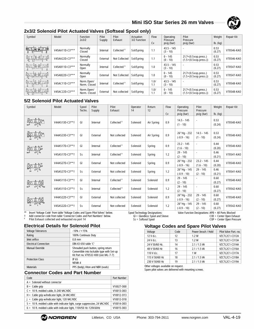
Littleton, CO USA Phone: 303-794-2611 www.norgren.com VAL-4-19
** Insert ‘Voltage Code’ from table ‘Voltage Codes and Spare Pilot Valves’ below.† Add connector code from table ‘Connector Codes and Part Numbers’ below.x Pilot Exhaust collected and exhausted via port 14
Spool Technology Designations: Valve Function Designations: APB = All Ports BlockedGl = Glandless Spool and Sleeve COE = Center Open ExhaustSs = Softseal Spool COP = Center Open Pressure
Mini ISO Star Series 26 mm Valves
Symbol Model Spool Pilot Pilot Operator Return Flow Operating Pilot Weight Repair KitTechn. Supply Exhaust 14 12 Pressure Pressure
Cv psig (bar) psig (bar) lb. (kg)
14.5 - 145 - 0.53V44A513D-C3**† Gl Internal Collected x Solenoid Air Spring 0.9
(1 - 10) (0.24)V70540-KAO
26" Hg - 232 14.5 - 145 0.53V44A523D-C3**† Gl External Not collected Solenoid Air Spring 0.9
(-0.9 - 16) (1 - 10) (0.24)V70540-KAO
V44A517D-C3**† Gl Internal Collected x Solenoid Spring 0.923.2 - 145 - 0.44
V70540-KAO(1.6 - 10) (0.20)
V45A517D-C3**† Ss Internal Collected x Solenoid Spring 1.229 - 145 - 0.46
V70541-KAO(2 - 10) (0.21)
V44A527D-C3**† Gl External Not collected Solenoid Spring 0.926" Hg - 232 23.2 - 145 0.44
V70540-KAO(-0.9 - 16) (1.6 - 10) (0.20)
V45A527D-C3**† Ss External Not collected Solenoid Spring 1.226" Hg - 145 29 - 145 0.46
V70541-KAO(-0.9 - 10) (2 - 10) (0.21)
V44A511D-C3**† Gl Internal Collected x Solenoid Solenoid 0.929 - 145 - 0.60
V70540-KAO(2 - 10) (0.27)
V45A511D-C3**† Ss Internal Collected x Solenoid Solenoid 1.229 - 145 - 0.60
V70542-KAO(2 - 10) (0.27)
V44A522D-C3**† Gl External Not collected Solenoid Solenoid 0.926" Hg - 232 29 - 145 0.60
V70540-KAO(-0.9 - 16) (2 - 10) (0.27)
V45A522D-C3**† Ss External Not collected Solenoid Solenoid 1.226" Hg - 145 29 - 145 0.60
V70542-KAO(-0.9 - 10) (2 - 10) (0.27)
4 214 12
351
84
4 214
351
84
12
4 214 12
351
84 82
4 214 12
1435
18284
4 21412
1435
1
84
4 214 12
35114
84
5/2 Solenoid Pilot Actuated Valves
Symbol Model Function Pilot Pilot Actuation Flow Operating Pilot Weight Repair Kit2x3/2 Supply Exhaust 3/2 Function Pressure Pressure
Cv psig (bar) psig (bar) lb. (kg)
V45AA11D-C3***Normally
Internal Collected x Sol/Spring 1.143.5 - 145 - 0.53
V70546-KAOClosed (3 - 10) (0.27)
V45AA22D-C3***Normally
External Not Collected Sol/Spring 1.10 - 145 21.7+(0.5xop.press.) 0.53
V70546-KAOClosed (0 - 10) (1.5+(0.5xop.press.)) (0.27)
V45AB11D-C3***Normally
Internal Collected x Sol/Spring 1.043.5 - 145 - 0.53
V70547-KAOOpen (3 - 10) (0.27)
V45AB22D-C3***Normally
External Not Collected Sol/Spring 1.00 - 145 21.7+(0.5xop.press.) 0.53
V70547-KAOOpen (0 - 10) (1.5+(0.5xop.press.)) (0.27)
V45AC11D-C3***Norm.Open/
Internal Collected x Sol/Spring1.0/ 43.5 - 145 - 0.53
V70548-KAONorm. Closed 1.1 (3 - 10) (0.27)
V45AC22D-C3***Norm.Open/
External Not collected Sol/Spring1.0/ 0 - 145 21.7+(0.5xop.press.) 0.53
V70548-KAONorm. Closed 1.1 (0 - 10) (1.5+(0.5xop.press.)) (0.27)
2x3/2 Solenoid Pilot Actuated Valves (Softseal Spool only)
5 184 823
4 210 1014 12
84 823
4 214 1210 10
5 184
1482
3
4 210 1014 12
8410
823
4 214 1210 10
5 184 823
4 210 1214 10
5 184 82
3
4 210 1214 10
10
Electrical Details for Solenoid PilotVoltage Tolerances -10% / +15%
Rating 100% Continuos Duty
Inlet orifice 0.8 mm
Electrical Connection DIN 43 650 table 'C'
Manual Override Shrouded push button, spring returnConvertible into lockable type with Set-up Kit Part no. V70532-K00 (see VAL-7-7)
Protection Class IP 65 NEMA 4
Materials PPS (body), Viton and NBR (seals)
Voltage Codes and Spare Pilot ValvesVoltage Code Power Inrush / Hold Pilot Valve Part.-no.
12 V d.c. 12 1.2 W VZC7L2C1-C312A
24 V d.c. 13 1.2 W VZC7L2C1-C313A
24 V 50/60 Hz. 14 2.1 / 1.5 VA VZC7L2C1-C314A
48 V 50/60 Hz 16 2.1 / 1.5 VA VZC7L2C1-C316A
110 V d.c. 17 1 W VZC7L2C1-C317A
115 V 50/60 Hz 18 2.1 / 1.5 VA VZC7L2C1-C318A
230 V 50/60 Hz 19 2.1 / 1.5 VA VZC7L2C1-C319A
Other voltages available on request.Spare pilot valves are delivered with mounting screws.
Connector Codes and Part NumberCode Part Number
A = Solenoid without connector
B = Cable grip V10027-D00
C = 10 ft. molded cable, 0-240 VAC/VDC V10013-D03
H = Cable grip w/indicator light, 24 VAC/VDC V10012-D13
J = Cable grip w/indicator light, 120 VAC/VDC V10012-D18
5 = 10 ft. molded cable with indicator light, surge suppression, 24 VAC/VDC V10014-D03
6 = 10 ft. molded cable with indicator light, 110V/50 Hz-120V.60Hz V10015-D03

VAL-4-20 Littleton, CO USA Phone: 303-794-2611 www.norgren.com
Mini ISO Star Series 26 mm Valves
Symbol Model Spool Operator Return Flow Operating Pressure Pilot Pressure Weight Repair KitTechn. 14 12 Cv psig (bar) psig (bar) lb. (kg)
V44A537A-X0090 Gl Air Spring 0.926" Hg - 232 23 - 232 0.40
V70540-KAO(-0.9 - 16) (1.6 - 16) (0.18)
V45A537A-X0090 Ss Air Spring 1.226" Hg - 145 29 - 145 0.40
V70541-KAO(-0.9 - 10) (2 - 10) (0.18)
V44A533A-X0020 Gl Air Air 0.926" Hg - 232 29 - 232 0.44
V70540-KAO(-0.9 - 16) (2 - 16) (0.20)
V45A533A-X0020 Ss Air Air 1.226" Hg - 145 29 - 145 0.44
V70542-KAO(-0.9 - 10) (2 - 10) (0.20)
5/2 Air Pilot Actuated Valves
4 214 12
351
4 214 12
351
5/3 Solenoid Pilot Actuated ValvesSymbol Model Spool Valve Pilot Pilot Operator Return Flow Operating Pilot Weight Repair Kit
Techn. Function Supply Exhaust 14 12 Pressure PressureCv psig (bar) psig (bar) lb. (kg)
V44A611D-C3**† Gl APB Internal Collected x Solenoid Solenoid 0.929 - 145 - 0.62
V70540-KAO(2 - 10) (0.28)
V45A611D-C3**† Ss APB Internal Collected x Solenoid Solenoid 1.1536.3 - 145 - 0.59
V70543-KAO(2.5 - 10) (0.27)
V44A622D-C3**† Gl APB External Not collected Solenoid Solenoid 0.926" Hg - 232 29 - 145 0.62
V70540-KAO(-0.9 - 16) (2 - 10) (0.28)
V45A622D-C3**† Ss APB External Not collected Solenoid Solenoid 1.1526" Hg - 145 36.3 - 145 0.59
V70543-KAO(-0.9 - 10) (2.5 - 10) (0.27)
V44A711D-C3**† Gl COE Internal Collected x Solenoid Solenoid 0.929 - 145 - 0.62
V70540-KAO(2 - 10) (0.28)
V45A711D-C3**† Ss COE Internal Collected x Solenoid Solenoid 1.1536.3 - 145 - 0.59
V70544-KAO(2.5 - 10) (0.27)
V44A722D-C3**† Gl COE External Not collected Solenoid Solenoid 0.926" Hg - 232 29 - 145 0.62
V70540-KAO(-0.9 - 16) (2 - 10) (0.28)
V45A722D-C3**† Ss COE External Not collected Solenoid Solenoid 1.1526" Hg - 145 36.3 - 145 0.59
V70544-KAO(-0.9 - 10) (2.5 - 10) (0.27)
V44A811D-C3**† Gl COP Internal Collected x Solenoid Solenoid 0.929 - 145 - 0.62
V70540-KAO(2 - 10) (0.28)
V45A811D-C3**† Ss COP Internal Collected x Solenoid Solenoid 1.1536.3 - 145 - 0.59
V70545-KAO(2.5 - 10) (0.27)
V44A822D-C3**† Gl COP External Not collected Solenoid Solenoid 0.926" Hg - 232 29 - 145 0.62
V70540-KAO(-0.9 - 16) (2 - 10) (0.28)
V45A822D-C3**† Ss COP External Not collected Solenoid Solenoid 1.1526" Hg - 145 36.3 - 145 0.59
V70545-KAO(-0.9 - 10) (2.5 - 10) (0.27)
4 2 1214
351
84 82
4 2 1214
351
84 82
4 2 1214
351
84 82
4 2 1214
1435
184 82
4 2 1214
1435
184 82
4 2 1214
1435
184 82
** Insert ‘Voltage Code’ from table ‘Voltage Codes and Spare Pilot Valves’ on VAL-4-19.† Add connector code from table ‘Connector Codes and Part Numbers’ on VAL-4-19.x Pilot Exhaust collected and exhausted via port 14
Spool Technology Designations: Valve Function Designations: APB = All Ports BlockedGl = Glandless Spool and Sleeve COE = Center Open ExhaustSs = Softseal Spool COP = Center Open Pressure
Symbol Model Function 2x3/2 Actuation Flow Operating Pressure Pilot Pressure Weight Spares Kit3/2 Function Cv psig (bar) psig (bar) kg (lb.)
V45AA33A-X0020 Normally Closed Air/Spring 1.10 - 145 1.5 + (0.5xop. pressure) 0.20
V70546-KAO(0 - 10) (21.7 + (0.5xop. pressure)) (0.40)
V45AB33A-X0020 Normally Open Air/Spring 1.00 - 145 1.5 + (0.5xop. pressure) 0.20
V70547-KAO(0 - 10) (21.7 + (0.5xop. pressure)) (0.40)
V45AC33A-X0020Normally Open/
Air/Spring 1.0/1.10 - 145 1.5 + (0.5xop. pressure) 0.20
V70548-KAONormally Closed (0 - 10) (21.7 + (0.5xop. pressure)) (0.40)
2x3/2 Air Pilot Actuated Valves (Softseal Spool)
5 1 3
4 210 12
1014
5 1 3
4 210 10
1214
5 1 3
4 214 12
1010

Littleton, CO USA Phone: 303-794-2611 www.norgren.com VAL-4-21
Mini ISO Star Series 26 mm Valves
Symbol Model Spool Valve Function Operator Return Flow Operating Pressure Pilot Pressure Weight Spares KitTechn. 14 12 Cv psig (bar) psig (bar) lb. (kg)
V44A633A-X0020 Gl APB Air Air 0.926" Hg - 232 29 - 232 0.48
V70540-KAO(-0.9 - 16) (2 - 16) (0.22)
V45A633A-X0020 Ss APB Air Air 1.1526" Hg - 145 36 - 145 0.46
V70543-KAO(-0.9 - 10) (2.5 - 10) (0.21)
V44A733A-X0020 Gl COE Air Air 0.926" Hg - 232 29 - 232 0.48
V70540-KAO(-0.9 - 16) (2 - 16) (0.22)
V45A733A-X0020 Ss COE Air Air 1.1526" Hg - 145 36 - 145 0.46
V70544-KAO(-0.9 - 10) (2.5 - 10) (0.21)
V44A833A-X0020 Gl COP Air Air 0.926" Hg - 232 29 - 232 0.48
V70540-KAO(-0.9 - 16) (2 - 16) (0.22)
V45A833A-X0020 Ss COP Air Air 1.1526" Hg - 145 36 - 145 0.46
V70545-KAO(-0.9 - 10) (2.5 - 10) (0.21)
5/3 Air Pilot Actuated Valves
4 21214
351
4 21214
351
4 21214
351
Modular Sub-base Modular Sub-base Modular Sub-base Modular Sub-baseSide Ported without Pilot Ports Side Ported with Pilot Ports Side Ported (PIF) without Pilot Ports Side Ported (PIF) with Pilot Ports
V70525-PAF (1/8 NPTF) V70526-PAF (1/8 NPTF) V70525-2AF (3/8 PIF) V70526-2AF (3/8 PIF)
V70525-RAF (1/4 NPTF) V70526-RAF (1/4 NPTF) V70525-8AF (ø8 mm) V70526-8AF (ø8 mm)
V70525-BAF (G1/4) V70526-BAF (G1/4) V70525-YAF (ø10 mm) V70526-YAF (ø10 mm)
End Plate Kit Single Station Sub-base Fixed Length Sub-baseEnd Ported Side ported with Pilot Ports Bottom ported
V70524-SAC (3/8 NPTF) V70501-RAB (1/4 NPTF) V705**-RA0
V70524-CAC (G3/8) V70501-BAB (G1/4) **=02, 04, 06, 08, 10, 12 stations
Bases
Accessories
Intermediate Supply/Exhaust Module Single Valve Shut-Off Plate Single Pressure Regulator Plate Double Pressure Regulator Plate Flow Control Plate
V70529-RAO (1/4 NPTF) V70530-KAO (Port 1 blocked) V70527-KA1 (Port 1 reg.) V70527-KA4 (Ports 2+4 reg.) V70528-KAO (Ports 3+5)
V70529-BAO (G1/4) V70527-KA2 (Port 2 reg.)
V70527-KA3 (Port 4 reg.)
DIN EN 50 022 rail (3.28 feet) DIN-rail Mounting Kit Blanking Plate for unused station Blanking Disk to Modular Sub-base Manual Override Set-Up Kit
V10009-C00 (35x7.5mm) V70531-KA0 V70500-KAO V70522-K00 (Ports 1,3,5) V70532-K00
V10592-C01 (35x15mm) V70523-K00 (Ports 12+14)
Sandwich Plate with additional
Pressure Port 1 Transition Plate #18 →#26 mm Transition Plate #18 → #26 mm
V70535-RA0 1/4 NPTF V70436-K00 V70436-R00 1/4 NPTF
V70535-BA0 G1/4 V70436-B00 G1/4

Mini ISO Star Series 26 mm ValvesAll Dimensions in Inches (mm)
VAL-4-22 Littleton, CO USA Phone: 303-794-2611 www.norgren.com
V44A5*3D-C3*** 5/2 Single Solenoid Pilot ValveAir Spring Return
3.24
(82
)
1.38
(35
)0.
25 (
6.4)
M4
1.54
(39
)
Manual Override
0.75
(19
)
1.05
(26
.7)
5.11 (130)
V44A5*7D-C3*** and V45A5*7D-C3*** 5/2 Single Solenoid Pilot ValveMechanical Spring Return
3.24
(82
)
1.38
(35
)0.
25 (
6.4)
M4
Manual Override
0.75
(19
)
1.05
(26
.7)
1.47 (37.4)
4.03 (102)
V44A5**D-C3*** and V45A5**D-C3*** 5/2 Double Solenoid Pilot Valve
3.24
(82
)
1.38
(35
)0.
25 (
6.4)
M4
Manual Override
0.75
(19
)
1.05
(26
.7)
5.11 (130)
4.27 (108)
V44A***D-C3*** and V45A***D-C3*** 2x3/2 + 5/3 Double Solenoid Pilot Valve
V44A537A-X00*0 and V45A537A-X00*05/2 Single Air Pilot Valves
1.54
(39
)
1.38
(35
)0.
25 (
6.4)
M4
0.75
(19
)
1.05
(26
.7)
1.47 (37.4)
4.03 (102)
V44A*33A-X00*0 and V45A*33A-X00*02x3/2 + 5/2 + 5/3 Double Air Pilot Valve
5.11 (130)
1.54
(39
)
1.38
(35
)0.
25 (
6.4)
M4
0.75
(19
)
1.05
(26
.7)
3.24
(82
)
1.38
(35
)0.
25 (
6.4)
M4
Manual Override
0.75
(19
)
1.05
(26
.7)
5.11 (130)
4.27 (108)

Littleton, CO USA Phone: 303-794-2611 www.norgren.com VAL-4-23
Mini ISO Star Series 26 mm Valves
Conversion from internal to external pilot supply / collected pilot exhaust
The lowered and captive gasket between valve body and pilot valve defines and indicates pilot air supply as well as pilotexhaust function of the valve.
Internal pilot supply,pilot exhaust air collected and exhausted via port 14.
All solenoid pilot valves with code 1 at position 6 in the part number (e.g V45A51...) have the gasket mounted in this position on delivery.
External pilot supply from port 14 only,pilot exhaust air not collected but bleed through valve body.
All solenoid pilot valves with code 2 at position 6 in thepart number (e.g V45A52...) have the gasket mountedin this position on delivery.
blue gasketblue gasket
Note: Dismounting pilot valve gives access to gasket. Conversion from internal to external pilot supply (or vice versa)by turning the gasket.Caution: In this case part number and symbol on label shows different function. Therefore check gasket positionwhen mounting valve.
Air pilot actuated valvesExternal pilot supply.
blue gasket
Drawing includescover plate.
Drawing showsno pilot valve.
Solenoid pilot actuated valves
Air pilot actuated valves

VAL-4-24 Littleton, CO USA Phone: 303-794-2611 www.norgren.com
Mini ISO Star Series 26 mm Valves
Order a factory assembled manifold
V = Valve Product
45 = Mini ISO (Size 26mm)
X = Default (No Wireway)
02 to 20 stations
XXX = Default
A = Side Ported, without Pilot PortsE = Side Ported, with Pilot Ports
XX = single pressure application01-19 = Number of stations for dual
pressure into manifold
P = 3/8" NPTF (1,3,5), 1/8" NPTF (2,4)R = 3/8" NPTF (1,3,5), 1/4" NPTF (2,4)2 = 3/8" NPTF (1,3,5), 3/8" PIF (2,4)B = G3/8 (1,3,5), G1/4 (2,4)8 = G3/8 (1,3,5), 8mm PIF (2,4)Y = G3/8 (1,3,5), 10mm PIF (2,4)
The following ordering example details the information needed to order a 4-valve, single solenoid, 24 VDC, cable grip electricalconnector, single pressure manifold.
One Mini ISO manifold consisting of:Position Quantity Part No.
1-4 4 V44A513D-C313B1 V45RAX04-XXXXX
V 4 5 R A X 0 7 - X X X X X
Ordering Example

Mini ISO Star Series 26 mm ValvesAll Dimensions in Inches (mm)
Littleton, CO USA Phone: 303-794-2611 www.norgren.com VAL-4-25
x = Insert port type from table below
Individual components
Modular Sub-base 0.40 lbPorts 2+4 on side (0.18 kg)V70525-xAF
Modular Sub-base 0.40 lbPorts 2+4 on side (0.18 kg)Pilot Ports 12+14 on sideV70526-xAF
Modular Sub-base 0.40 lbPorts 2+4 on bottom (0.18 kg)V70525-BAE
Modular Sub-base 0.40 lbPorts 2+4 on bottom (0.18 kg)Pilot Ports 12+14 on sideV70526-BAE
End Plate Kit 0.80 lbSide Ported (0.36 kg)V70524-CAC (G3/8)V70524-SAC (3/8NPTF)End ported end caps1 left hand and 1right hand
Accessories
DIN EN 50022 rail 0.68 lb35 x 7.5 mm, 3.3' (1m) (0.31 kg)V10009-C00
DIN EN 50022 rail 2.25 lb35 x 15 mm, 3.3' (1m) (1.02 kg)V10592-C01
DIN rail 0.02 lbMounting Kit (0.01 kg)V70531-KAO
Blanking Disk to 0.02 lbModular Sub-base (0.01 kg)Ports 1, 3, 5V70522-K00
Blanking Disk to 0.02 lbModular Sub-base (0.01 kg)Ports 12+14V70523-K00
A
12 12 12
2 2 2
4 44
14 14 14
14 12
31
5
4 2
4 2
4 2
0.69
(17
.6)
1.26 (31.9)
2.08 (52.9)
D
B
A CC
0.69 (17.6)
0.42
(10
.8)
1.55
(39
.3)
1.94
(49
.4)
0.20 (5)
0.67 (17)
View Y
0.47 (12)
1.94
(49
.4)
Left Hand SideRight Hand Side
Y
0.18 (4.5)
3.07 (78.1)
0.18
(4.
5)
0.38
(9.
5)
1.07
(27
.1)
1.07
(27
.1)
*N x
1.0
7 (2
7.1)
0.12
(3)
2.19
(55
.5)
3.57
(90
.6)
5.43
(13
8)
0.73 (18.6)
1.71 (43.4)
2.69 (68.2)
3.54 (90)
0.70 (17.9)
2.71 (68.9)0.
91 (2
3.1)
1.22
(31.
1)
1.83
(46
.6)
* N = Number of stations
M5
M5
Modular Sub-bases parts for DIN rail or surface mounting
A
B
B
C
D
Code Ports 2+4 Ports 12+14P 1/8NPTF 10-32 UNFR 1/4NPTF 10-32 UNF2 3/8 PIF 10-32 UNFB G1/4 M58 ø 8 mm PIF M5Y ø 10 mm PIF M5
Bottom ported sub-base
Side ported sub-base
Bottom and side ported sub-base
Note:Port 14 used for external pilot air supply or for collected pilot air exhaust.Never plug port 14 when using valves with internal pilot air supply.Port 12 is not used, plugging not necessary.

Mini ISO Star Series 26 mm ValvesAll Dimensions in Inches (mm)
VAL-4-26 Littleton, CO USA Phone: 303-794-2611 www.norgren.com
3
1
5
14
4 2
12
0.86 (21.8) 0.86 (21.8)
A
0.39
(10
)
0.71
(18
)
0.22 (5.5) 0.04 (1)
0.22
(5.
5)
0.75
(19
)
1.06
(27
)
0.20
(5)
1.65
(42
)
M4
3.17 (80.5)
3.62 (92)
3.17 (80.5)
2.17 (55)
22 (0.87)0.22 (5.5)
0.24
(6)
0.47
(12
)
1.10
(28
)
0.53
(13.
5)
0.83
(21)
2.72 (69)
10-32 UNF
Single Station Sub-base - Side Ported with Pilot Ports
Model Port Size A Weightlb (kg)
V70501-RAB NPTF1/4side ported with pilot ports 0.24
V70501-BAB G1/4 (0.11)side ported with pilot ports
5
1
3
42
42
0.97
(24.
6)
0.94 (24) 1.06 (27)
3/8
NP
TF
0.22
(5.
5)
0.67 (17)
1.26 (32)
0.45 (11.5)
0.45
(11
.5)
1.48
(37
.5)
2.50
(63
.5)
1.00
(25
.4)
0.98
(24
.8)
B
A
0.30 (7.5)
X
View X
0.23 (5.9)
0.39
(10
)
1/4" NPTF
Fixed Length Sub-base - Bottom Ported
Model No. of A B WeightStations inch (mm) inch (mm) lb (kg)
V70502-RA0 2 3.27 2.68 0.88(83) (68) (0.40)
V70504-RA0 4 5.39 4.80 1.43(137) (122) (0.65)
V70506-RA0 6 7.52 6.93 2.00(191) (176) (0.91)
V70508-RA0 8 9.65 9.06 2.53(245) (230) (1.15)
V70510-RA0 10 11.77 11.18 3.11(299) (284) (1.41)
V70512-RA0 12 13.90 13.31 3.66(353) (338) (1.66)
Note: This sub-base is suitable for solenoidpilot actuated valves with internal pilot air supply only.

Mini ISO Star Series 26 mm ValvesAll Dimensions in Inches (mm)
Littleton, CO USA Phone: 303-794-2611 www.norgren.com VAL-4-27
Model Port Size A Weightlb (kg)
V70529-RAO 1/4NPTF 0.26V70529-BAO G1/4 (0.12)
Intermediate Supply / Exhaust Module
Model Description Weightlb (kg)
V70530-KAO Single Shut-Off Plate 0.28 supplied with gasket (0.13)
Model Description Weightlb (kg)
V70528-KAO Flow Regulator 0.37 supplied with gasket (0.17)
Model Description Weightlb (kg)
V70500-KAO Blanking Plate for 0.11 blocking of unused stations (0.05)(supplied with gasket)
Provides additional porting on Modular orFixed Length Sub-base.Occupies one valve station.Supplied with gasket for both sub-bases.
Blanking Plate
M4
0.39
(10
)0.
24 (
6)0.
75 (
19)
1.02
(26
)
2.76 (70)
5
1
3
M4
0.75
(19
)
1.02
(26
)
1.73 (44)
0.51
(13)
0.63
(16)
1.02
(26
)0.
24 (
6)
3.03 (77)
A0.43 (11)
2.48 (63)
1.30 (33)
Single Valve Shut-Off Plate
Flow Regulator Plate
1.30 (33)
M4
0.85
(21.
5)0.
26 (6
.5)
0.31
(8)
0.53 (13.4)
0.75
(19
)
1.06
(26
.8)
3.83 (97)
0.40
(10.
3)
0.32 (8.1)M4
0.85
(21.
5)0.
26 (
6.5)
0.75
(19
)
1.06
(26
.8)
3.69 (93.7)
4.75 (120.7)
5.37 (136.5)
Can be used to:- Improve supply flow- Increase exhaust capacity- Pneumatically separate valves for fail
save emergency- Multipressure system and system solutions
Allows individual exchange of valve, whilevalve island is pressurized by port 1.
Note: Flow restricted to max. Cv of 0.5
Dual Regulation of Exhaust Ports 3 and 5
1.0
0.8
0.6
0.4
0.2
00 1 2 3 4 5 6 7 8 9 10
Number of turns from closed
Exh
aust
Flo
w (
Po
rts
3+5)
[C
v]
Flow: Port 1� 2 and 1� 4 remain unchangedFlow measured at 87 psig inlet, Pressure drop 15 psi

Mini ISO Star Series 26 mm ValvesAll Dimensions in Inches (mm)
VAL-4-28 Littleton, CO USA Phone: 303-794-2611 www.norgren.com
Pressure Regulator Plates (including gauges)
3.52 (89.5)1.57 (40)ø 1.02 (ø 26)
1.04 (26.5)
ø 0
.87
(ø 2
2.3)
0.75
(19
)
2.89
(73
.5)
1.49
(38
)0.
33 (
8.5)
6.37 (162)
3.52 (89.5) 1.57 (40)ø 1.02 (ø 26)
1.04 (26.5)
ø 0
.87
(ø 2
2.3)
0.75
(19
)
2.89
(73
.5)
1.49
(38
)
0.33
(8.
5)
6.37 (162)
7.05 (179)
9.56 (243)
ø 1.02 (ø26)
ø22
.3 2.89
(73
.5)
1.49
(38
)0.
33 (
8.5)
1.04 (26.5)
Model Description Weight lb (kg)
V70527-KA4 Regulation 1.23 of Ports 2+4 (0.56)
Model Description Weight lb (kg)
V70527-KA3 Regulation 0.79 of Port 4 (0.36)
Model Description Weight lb (kg)
V70527-KA2 Regulation 0.79 of Port 2 (0.36)
Model Description Weight lb (kg)
V70527-KA1 Regulation 0.36 of Port 1 (0.79)
Flow Characteristics see page VAL-4-29
Flow Characteristics see page VAL-4-29
Flow Characteristics see page VAL-4-29
Flow Characteristics see page VAL-4-29
Maximum inlet pressure 232 psig(16 bar)
Regulated pressure 7.25–145 psig(0.5–10 bar)
Maximum inlet pressure 232 psig(16 bar)
Regulated pressure 7.25–145 psig(0.5–10 bar)
Maximum inlet pressure 232 psig(16 bar)
Regulated pressure 7.25–145 psig(0.5–10 bar)
Maximum inlet pressure 232 psig(16 bar)
Regulated pressure 7.25–145 psig(0.5–10 bar)
3.52 (89.5)1.57 (40)ø 1.02 (ø 26)
1.04 (26.5)
ø 0
.87
(ø 2
2.3)
0.75
(19
)
2.89
(73
.5)
1.49
(38
)0.
33 (
8.5)
6.37 (162)

Littleton, CO USA Phone: 303-794-2611 www.norgren.com VAL-4-29
Mini ISO Star Series 26 mm Valves
Flow Characteristics for Pressure Regulator Plates Hysterisis
1.30 (33)
M4
0.85
(21.
5)0.
26 (6
.5)
0.71
(9.
5)
0.53 (13.4)
1/4" NPTF
1
0.75
(19
)
1.06
(26
.8)
0.15
(3.
9)
3.11 (79)
Sandwich Plate with additional Pressure Port 1 Model Description Weight lb (kg)
V70535-RAO Sandwich Plate 0.26with additional (0.12)Port 1, suppliedwith gasket
4 2
5 31 1e
(180) (360) (540) (720) (qn l/min)
Inlet pressure = 116 psig (8 bar)
Reg
ula
ted
pre
ssu
re p
sig
(b
ar)
p1 = 145 psig
(8)
(6)(6.3)
(5.3)
(4)
(2)
0
(900)
116
9187
77
58
29
6.4 12.7 19 25.4 31.8 scfm
(10 bar)
0
Starting Point
Inlet pressure
Ou
tlet
pre
ssu
re
(2.5)
(2.4)
(2.2)
(2.0)
(1.8)
(1.6)(1.5)
(2) (3) (4) (5) (6) (7) (8) (9) (10)29 44 58 73 87 102 116 131 145
36
35
32
29
26
2322
psig
psig
(bar)
(bar)
All Dimensions in Inches (mm)

VAL-4-30 Littleton, CO USA Phone: 303-794-2611 www.norgren.com
Mini ISO Star Series Valves
Mini ISO Star Valve Numbering System
V = Valve Product
D = Default (Solenoid Pilot) A = Default (Air Pilot)
X = Air Pilot
0 = Default
02 = Double Air Pilot09 = Single Air Pilot
0 = Default
C = Solenoid Pilot
3 = Non-locking Override
12 = 12 VDC13 = 24 VDC14 = 24 VAC16 = 48 VAC17 = 110 VDC18 = 120 VAC19 = 240 VAC
A = Solenoid without ConnectorB = Cable gripC = 10 ft. molded cable, 0-240 VAC/VDCH = Cable grip w/indicator light, 24 VAC/VDCJ = Cable grip w/indicator light, 120 VAC/VDC5 = 10 ft. molded cable with indicator light,
surge suppression, 24 VAC/VDC6 = 10 ft. molded cable with indicator light, 120 VAC/VDC
5 = Subbase Valve A = Subbase Valve
40 = Mini ISO 18 mm Glandless41 = Mini ISO 18 mm Soft Seal
44 = Mini ISO 26 mm Glandless45 = Mini ISO 26 mm Soft Seal
1 = Solenoid, internal pilot2 = Solenoid, external pilot3 = Air Pilot
1 = Solenoid, internal pilot2 = Solenoid, external pilot3 = Air Spring Return/Air Pilot7 = Spring Return
A = 2 x 3/2 NC (V41,V45 only)B = 2 x 3/2 NO (V41,V45 only)C = 2 x 3/2 NO/NC (V41,V45 only)5 = 5/26 = 5/3 APB7 = 5/3 COE8 = 5/3 COP
V 4 5 A 5 1 7 D – C 3 1 8 B

Littleton, CO USA Phone: 303-794-2611 www.norgren.com VAL-5-1
Section 5
Norgren ISO Star Series Precision Spool and Sleeve Directional Control ValvesAvailable in sizes 1, 2, and 3, these compact, high flow valves feature fast, constant response times, and long, trouble-free life. Both 5/2 and 5/3 configurations in 1/4", 3/8", and 1/2" port subbases are available, along with accessoriessuch as integral flow controls and sandwich regulators. These Swiss made valves are 100% corrosive resistant andare robust and reliable for use in harsh, industrial environments.
ISO Star Series ValvesA long life (100 to 200 million
cycles) precision spool andsleeve directional control
air valve
ContentsFeatures and Benefits . . . . . . . . . . . .VAL-5-2Specifications and Technical Data . . .VAL-5-3Accessories . . . . . . . . . . . . . . . . . . . .VAL-5-8Dimensional Data . . . . . . . . . . . . . . . .VAL-5-9Product Numbering Information . . .VAL-5-14

VAL-5-2 Littleton, CO USA Phone: 303-794-2611 www.norgren.com
ISO Star Series Valves
ISO*Star SeriesValves
Manual override controlon solenoid
Rated for 100–200million cycles
Norgren ISO*Star Series precision spool and sleeve directional control valves areavailable in sizes 1, 2, and 3. These compact high flow valves feature fast andconstant response times and long, trouble-free life. Many accessories are availableincluding integral flow controls and sandwich regulators. Both 5/2 and 5/3configurations in 1/4'', 3/8'', and 1/2'' port subbases are available. Manufacturedin Switzerland, these valves are 100% corrosive resistant, robust and reliable for use in harsh, industrial environments.
Design Features Provide Long Life and High ReliabilityNorgren ISO*Star Series valves feature a hard-anodized NITUFF® coated matched spool and sleeve assembly which is rated for 100-200 million cycles. The spool and sleeve is 100% non-corrosive, requires no minimum number of operations, and will not stick even after extended periods of standstill. This rugged, simple design provides problem-free operation in the harshest industrial environments. Just fit and forget!
The“Fit and Forget”Solution
Integral low costflow controls
Available in sizes 1, 2, and 3
ISO 5599/1 interface
Captive mounting screws and subbase gasket
Low friction forces whichdecrease response time

Littleton, CO USA Phone: 303-794-2611 www.norgren.com VAL-5-3
ISO Star Series Valves
SpecificationsFluids: 40µm filtered, lubricated or nonlubricated, compressed air
or vacuum serviceMain Valve Inlet Pressure Range:
26" Hg vacuum to 150 psig (10 bar)Minimum Pilot Pressures:
Single Operator: 14.5 psig (1 bar)Double Operators: 29 psig (2 bar)
Ambient Temperature Range: 5° to 120°F* (-15 to 50°C)Inlet Temperature Range: 5° to 175°F* (-15° to 80°C)
*With dew point of supply air less than air temperature below 35°F (2°C).
Subbase SpecificationsThread Types: ISO G or NPT availableAll Pilot Supply Ports: 1/8"Size 1 Single Subbase: 1/4"Size 1 Manifolding Subbase: 1/4" cylinder ports, 3/8" supply and
exhaust ports in end platesSize 2 Single Subbase: 3/8"Size 2 Manifolding Subbase: 3/8" cylinder ports, 1/2" supply and
exhaust ports in end platesSize 3 Single Subbase: 1/2"Size 3 Manifolding Subbase: 1/2" cylinder ports, 1" supply and
exhaust ports in end plates
Average Flow Factor (Cv)†
Size 1: Cv 1.2Size 2: Cv 2.4Size 3: Cv 4.0†Flow rating determined in accordance with ANSI/(NFPA) T3.21.3, Pneumatic fluid power –
Flow test procedure and reporting method – for fixed orifice components.
Standard Solenoid Pilot Operator SpecificationsVoltages and Power Requirements:Standard: 120V/60Hz-110V/50Hz: 2.5WOptional: 24V/60Hz-24V/50Hz: 2.5W
12 VDC: 2W24 VDC: 2W240V/60Hz-220V/50Hz: 5.0W
Duty: Continuous at 90 to 105 % of rated voltage.Coil Type: Class H. Molded with three-pin plug-in connectorEnclosure Classification: NEMA 4 and DIN 40050 – IP 65Override: Manual, locking/nonlocking.Electrical Plug-In Connection: Cable grip for cables from
1/4" to 5/16" (6 mm) dia. standardElectrical Spade Connections on the operator receptacle conform to industry
standard form B for 3-pin connectors, 11 mm spacing.
Valve MaterialsBody: Aluminum die-castSpool & Sleeve: Aluminum hard anodized (NITUFF® coated)Valve Seals: NitrilePilot Seals: VitonPlastic Parts: POM & PA6-3-TScrews: Steel, zinc platedLocking Plate: Zinc die-castSpeed Controls: BrassSolenoid Operators:
Base: PPS plasticPlunger & Spring: Stainless steelSolenoid Coil Housing: Epoxy thermosetPiston: Acetal thermoplasticBody: Zinc
Response Time (ON/OFF)Size 1: 20/34 msec ±20%Size 2: 30/50 msec ±20%Size 3: 48/48 msec ±20%Note: Response times measured at 90 psig (6 bar) with a 5/2,
single solenoid valve configuration.
Valve Graphic Symbols
ISO*Star Precision Spool
5/2
5/3All ports blockedmid postion
5/3Center open exhaustmid postion
5/3Center open pressuremid postion
● Hard-anodized aluminum spool andsleeve with NITUFF® coating
● Suitable for lube, non-lube or dry air applications
● Lightweight aluminum construction
● Precision matched spool and sleeve
● No minimum number of operations required
● Rated for 100-200 million cycles
ISO*Star accessories include single and dualsandwich regulators, sandwich flow controls,check valve sandwich plates, port #1 auxiliarypressure plates, transition plates, blankingplates and isolating plugs.
Technical Data

ISO Series Valves
● NITUFF® coated non-corrosive spool and sleevefor long trouble free life (100 million plus cycles)
● Integral flow controls for cylinder speed control onsize #1, and #2 models
● Low power solenoids with manual overrideoptions
● End and CNOMO solenoid pilots
● Base mounted soft start valves available
● Minimal maintenance
Technical DataMedium:
Compressed air, 40µm filtered, lubricated or non-lubricatedOperation:
Glandless spool valve, solenoid pilot or air pilot actuatedMounting:
On sub-basesSizes:
#1#2#3
Operating Pressure:Maximum pressure 145 psig (10 bar) solenoid pilot actuated valves
with internal pilot supply232 psig (16 bar) solenoid pilot actuated valves
with external pilot supply232 psig (16 bar) air pilot actuated valvesDetails of minimum and maximum pilot pressure see VAL-5-3
Flow Characteristics (unregulated):Size Cv ‘C’ ‘b’ ‘A’ l/min Kv#1 1.2 5.5 0.06 19.7 1230 1.08#2 2.4 10.7 0.12 39.2 2450 2.16#3 4.0 17.9 0.07 64.0 4000 3.52
Ambient Temperature:5°F* to 122°F (–15°C to 50°C) solenoid pilot actuated valves5°F* to 176°F (–15°C to 80°C) air pilot actuated valves*Consult our Technical Service for use below 36°F (2°C)
Materials:Die cast aluminum body. Hard anodized, Teflon coated, matchedaluminum spool and sleeve. Viton and nitrile rubber seals. Zinc diecast locking plate. POM plastic parts. Zinc plated screws. Brass flowregulators.
Ordering Information
To order select model number, add voltagecode and connector code, e.g. SXE 0573-A60-00/13JB for a 5/2 double end solenoid pilotsize #1 valve with internal pilot air supply,integral flow regulators, shrouded push buttonlockable manual override, 22 mm coil 24V d.c.with cable grip connector.
VAL-5-4 Littleton, CO USA Phone: 303-794-2611 www.norgren.com
5/2
5/3 All ports blocked mid position
5/3 Center open exhaustmid position
5/3Center open pressuremid position
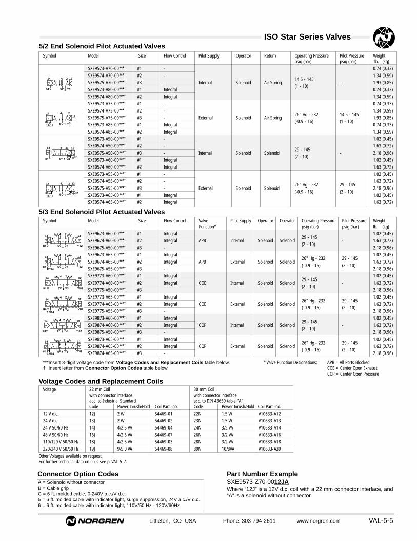
Littleton, CO USA Phone: 303-794-2611 www.norgren.com VAL-5-5
ISO Star Series Valves
Symbol Model Size Flow Control Pilot Supply Operator Return Operating Pressure Pilot Pressure Weightpsig (bar) psig (bar) lb. (kg)
SXE9573-A70-00***† #1 - 0.74 (0.33)
SXE9574-A70-00***† #2 - 1.34 (0.59)
SXE9575-A70-00***† #3 - Internal Solenoid Air Spring14.5 - 145
- 1.93 (0.85)
SXE9573-A80-00***† #1 Integral(1 - 10)
0.74 (0.33)
SXE9574-A80-00***† #2 Integral 1.34 (0.59)
SXE9573-A75-00***† #1 - 0.74 (0.33)
SXE9574-A75-00***† #2 - 1.34 (0.59)
SXE9575-A75-00***† #3 - External Solenoid Air Spring26" Hg - 232 14.5 - 145
1.93 (0.85)
SXE9573-A85-00***† #1 Integral(-0.9 - 16) (1 - 10)
0.74 (0.33)
SXE9574-A85-00***† #2 Integral 1.34 (0.59)
SXE0573-A50-00***† #1 - 1.02 (0.45)
SXE0574-A50-00***† #2 - 1.63 (0.72)
SXE0575-A50-00***† #3 - Internal Solenoid Solenoid29 - 145
- 2.18 (0.96)
SXE0573-A60-00***† #1 Integral(2 - 10)
1.02 (0.45)
SXE0574-A60-00***† #2 Integral 1.63 (0.72)
SXE0573-A55-00***† #1 - 1.02 (0.45)
SXE0574-A55-00***† #2 - 1.63 (0.72)
SXE0575-A55-00***† #3 - External Solenoid Solenoid26" Hg - 232 29 - 145
2.18 (0.96)
SXE0573-A65-00***† #1 Integral(-0.9 - 16) (2 - 10)
1.02 (0.45)
SXE0574-A65-00***† #2 Integral 1.63 (0.72)
4 214 12
35 184
4 214 12
35 18482
4 2
35 184
1214
12/1482
4 2
35 184
1214
12/14
Symbol Model Size Flow Control Valve Pilot Supply Operator Operator Operating Pressure Pilot Pressure WeightFunction* psig (bar) psig (bar) lb. (kg)
SXE9673-A60-00***† #1 Integral 1.02 (0.45)
SXE9674-A60-00***† #2 Integral APB Internal Solenoid Solenoid29 - 145
- 1.63 (0.72)
SXE9675-A50-00***† #3 -(2 - 10)
2.18 (0.96)
SXE9673-A65-00***† #1 Integral 1.02 (0.45)
SXE9674-A65-00***† #2 Integral APB External Solenoid Solenoid26" Hg - 232 29 - 145
1.63 (0.72)
SXE9675-A55-00***† #3 -(-0.9 - 16) (2 - 10)
2.18 (0.96)
SXE9773-A60-00***† #1 Integral 1.02 (0.45)
SXE9774-A60-00***† #2 Integral COE Internal Solenoid Solenoid29 - 145
- 1.63 (0.72)
SXE9775-A50-00***† #3(2 - 10)
2.18 (0.96)
SXE9773-A65-00***† #1 Integral 1.02 (0.45)
SXE9774-A65-00***† #2 Integral COE External Solenoid Solenoid26" Hg - 232 29 - 145
1.63 (0.72)
SXE9775-A55-00***† #3 -(-0.9 - 16) (2 - 10)
2.18 (0.96)
SXE9873-A60-00***† #1 Integral 1.02 (0.45)
SXE9874-A60-00***† #2 Integral COP Internal Solenoid Solenoid29 - 145
- 1.63 (0.72)
SXE9875-A50-00***† #3 -(2 - 10)
2.18 (0.96)
SXE9873-A65-00***† #1 Integral 1.02 (0.45)
SXE9874-A65-00***† #2 Integral COP External Solenoid Solenoid26" Hg - 232 29 - 145
1.63 (0.72)
SXE9874-A65-00***† #3 -(-0.9 - 16) (2 - 10)
2.18 (0.96)
5/3 End Solenoid Pilot Actuated Valves
4 2
35 1
1214
84 82
4 2
35 1
1214
84 82
4 2
35 1
1214
84 82
4 2
35 1
1214
8412/14
82
4 2
35 1
1214
84 8212/14
4 2
35 1
1214
8412/14
82
5/2 End Solenoid Pilot Actuated Valves
Voltage Codes and Replacement Coils
Connector Option Codes
Voltage 22 mm Coil 30 mm Coilwith connector interface with connector interface acc. to Industrial Standard acc. to DIN 43650 table "A"Code Power Inrush/Hold Coil Part.-no. Code Power Inrush/Hold Coil Part.-no.
12 V d.c. 12J 2 W 54469-01 22N 1.5 W V10633-A12
24 V d.c. 13J 2 W 54469-02 23N 1.5 W V10633-A13
24 V 50/60 Hz 14J 4/2.5 VA 54469-04 24N 3/2 VA V10633-A14
48 V 50/60 Hz 16J 4/2.5 VA 54469-07 26N 3/2 VA V10633-A16
110/120 V 50/60 Hz 18J 4/2.5 VA 54469-03 28N 3/2 VA V10633-A18
220/240 V 50/60 Hz 19J 9/5.0 VA 54469-08 89N 10/8VA V10633-A39
Other Voltages available on request.For further technical data on coils see p. VAL-5-7.
A = Solenoid without connectorB = Cable gripC = 6 ft. molded cable, 0-240V a.c./V d.c.5 = 6 ft. molded cable with indicator light, surge suppression, 24V a.c./V d.c.6 = 6 ft. molded cable with indicator light, 110V/50 Hz - 120V/60Hz
Part Number ExampleSXE9573-Z70-0012JAWhere “12J” is a 12V d.c. coil with a 22 mm connector interface, and“A” is a solenoid without connector.
* Valve Function Designations: APB = All Ports BlockedCOE = Center Open ExhaustCOP = Center Open Pressure
***Insert 3-digit voltage code from Voltage Codes and Replacement Coils table below.† Insert letter from Connector Option Codes table below.

VAL-5-6 Littleton, CO USA Phone: 303-794-2611 www.norgren.com
ISO Star Series Valves
* Valve Function Designations: APB = All Ports BlockedCOE = Center Open ExhaustCOP = Center Open Pressure
Symbol Model Size Flow Control Pilot Supply Operator Return Operating Pressure Pilot Pressure Weightpsig (bar) psig (bar) lb. (kg)
SXE9573-Z70-90***† #1 - 0.74 (0.33)
SXE9574-Z70-90***† #2 - 1.34 (0.59)
SXE9575-Z70-90***† #3 - Internal Solenoid Air Spring14.5 - 145
- 1.93 (0.85)
SXE9573-Z80-90***† #1 Integral(1 - 10)
0.74 (0.33)
SXE9574-Z80-90***† #2 Integral 1.34 (0.59)
SXE9573-Z75-90***† #1 - 0.74 (0.33)
SXE9574-Z75-90***† #2 - 1.34 (0.59)
SXE9575-Z75-90***† #3 - External Solenoid Air Spring26" Hg - 232 14.5 - 145
1.93 (0.85)
SXE9573-Z85-90***† #1 Integral(-0.9 - 16) (1 - 10)
0.74 (0.33)
SXE9574-Z85-90***† #2 Integral 1.34 (0.59)
SXE0573-Z50-90***† #1 - 1.02 (0.45)
SXE0574-Z50-90***† #2 - 1.63 (0.72)
SXE0575-Z50-90***† #3 - Internal Solenoid Solenoid29 - 145
- 2.18 (0.96)
SXE0573-Z60-90***† #1 Integral(2 - 10)
1.02 (0.45)
SXE0574-Z60-90***† #2 Integral 1.63 (0.72)
SXE0573-Z55-90***† #1 - 1.02 (0.45)
SXE0574-Z55-90***† #2 - 1.63 (0.72)
SXE0575-Z55-90***† #3 - External Solenoid Solenoid26" Hg - 232 29 - 145
2.18 (0.96)
SXE0573-Z65-90***† #1 Integral(-0.9 - 16) (2 - 10)
1.02 (0.45)
SXE0574-Z65-90***† #2 Integral 1.63 (0.72)
4 214 12
35 184
4 214 12
35 18482
4 2
35 184
1214
12/1482
4 2
35 184
1214
12/14
Symbol Model Size Flow Control Valve Pilot Supply Operator Operator Operating Pressure Pilot Pressure WeightFunction* psig (bar) psig (bar) lb. (kg)
SXE9673-Z60-90***† #1 Integral 1.02 (0.45)
SXE9674-Z60-90***† #2 Integral APB Internal Solenoid Solenoid29 - 145
- 1.63 (0.72)
SXE9675-Z50-90***† #3 -(2 - 10)
2.18 (0.96)
SXE9673-Z65-90***† #1 Integral 1.02 (0.45)
SXE9674-Z65-90***† #2 Integral APB External Solenoid Solenoid26" Hg - 232 29 - 145
1.63 (0.72)
SXE9675-Z55-90***† #3 -(-0.9 - 16) (2 - 10)
2.18 (0.96)
SXE9773-Z60-90***† #1 Integral 1.02 (0.45)
SXE9774-Z60-90***† #2 Integral COE Internal Solenoid Solenoid29 - 145
- 1.63 (0.72)
SXE9775-Z50-90***† #3(2 - 10)
2.18 (0.96)
SXE9773-Z65-90***† #1 Integral 1.02 (0.45)
SXE9774-Z65-90***† #2 Integral COE External Solenoid Solenoid26" Hg - 232 29 - 145
1.63 (0.72)
SXE9775-Z55-90***† #3 -(-0.9 - 16) (2 - 10)
2.18 (0.96)
SXE9873-Z60-90***† #1 Integral 1.02 (0.45)
SXE9874-Z60-90***† #2 Integral COP Internal Solenoid Solenoid29 - 145
- 1.63 (0.72)
SXE9875-Z50-90***† #3 -(2 - 10)
2.18 (0.96)
SXE9873-Z65-90***† #1 Integral 1.02 (0.45)
SXE9874-Z65-90***† #2 Integral COP External Solenoid Solenoid26" Hg - 232 29 - 145
1.63 (0.72)
SXE9875-Z55-90***† #3 -(-0.9 - 16) (2 - 10)
2.18 (0.96)
5/3 CNOMO Solenoid Pilot Actuated Valves (Consult factory for lead times)
4 2
35 1
1214
84 82
4 2
35 1
1214
84 82
4 2
35 1
1214
84 82
4 2
35 1
1214
8412/14
82
4 2
35 1
1214
84 8212/14
4 2
35 1
1214
8412/14
82
5/2 CNOMO Solenoid Pilot Actuated Valves (Consult factory for lead times)
Connector Option Codes
Other Voltages available on request.For further technical data on coils see p. VAL-5-7.
A = Solenoid without connectorB = Cable gripC = 6 ft. molded cable, 0-240V a.c./V d.c.5 = 6 ft. molded cable with indicator light, surge suppression, 24V a.c./V d.c.6 = 6 ft. molded cable with indicator light, 110V/50 Hz - 120V/60Hz
Part Number ExampleSXE9573-Z70-0012JAWhere “12J” is a 12V d.c. coil with a 22 mm connector interface, and“A” is a solenoid without connector.
***Insert 3-digit voltage code from Voltage Codes and Replacement Coils table below. † Insert letter from Connector Option Codes table below.
Voltage Codes and Replacement CoilsVoltage 22 mm Coil 30 mm Coil
with connector interface with connector interface acc. to Industrial Standard acc. to DIN 43650 table "A"Code Power Inrush/Hold Coil Part.-no. Code Power Inrush/Hold Coil Part.-no.
12 V d.c. 12J 2 W 54469-01 22N 1.5 W V10633-A12
24 V d.c. 13J 2 W 54469-02 23N 1.5 W V10633-A13
24 V 50/60 Hz 14J 4/2.5 VA 54469-04 24N 3/2 VA V10633-A14
48 V 50/60 Hz 16J 4/2.5 VA 54469-07 26N 3/2 VA V10633-A16
110/120 V 50/60 Hz 18J 4/2.5 VA 54469-03 28N 3/2 VA V10633-A18
220/240 V 50/60 Hz 19J 9/5.0 VA 54469-08 89N 10/8VA V10633-A39

Littleton, CO USA Phone: 303-794-2611 www.norgren.com VAL-5-7
ISO Star Series Valves
Symbol Model Size Flow Control Operator Return Operating Pressure Pilot Pressure Weightpsig (bar) psig (bar) lb. (kg)
SXP9573-170-00B #1 - 0.47 (0.21)
SXP9574-170-00B #2 - 1.02 (0.45)
SXP9575-170 #3 - Air Spring26" Hg - 232 23.2 - 232
1.63 (0.72)
SXP9573-180-00B #1 Integral(-0.9 - 16) (1.6 - 16)
0.47 (0.21)
SXP9574-180-00B #2 Integral 1.02 (0.45)
SXP0573-170-00B #1 - 0.68 (0.30)
SXP0574-170-00B #2 - 1.13 (0.50)
SXP0575-170 #3 - Air Air26" Hg - 232 29 - 232
1.63 (0.72)
SXP0573-180-00B #1 Integral(-0.9 - 16) (2 - 16)
0.68 (0.30)
SXP0574-180-00B #2 Integral 1.13 (0.50)
5/2 Air Pilot Actuated Valves
144 2
12
51
3
12144 2
51
3
Symbol Model Size Flow Control Valve Operator Operator Operating Pressure Pilot Pressure WeightFunction* psig (bar) psig (bar) lb. (kg)
SXP9673-180-00B #1 Integral 0.57 (0.25)
SXP9674-180-00B #2 Integral APB Air Air26" Hg - 232 29 - 232
1.32 (0.58)
SXP9675-170 #3 -(-0.9 - 16) (2 - 16)
1.82 (0.80)
SXP9773-180-00B #1 Integral 0.57 (0.25)
SXP9774-180-00B #2 Integral COE Air Air26" Hg - 232 29 - 232
1.32 (0.58)
SXP9775-170 #3 -(-0.9 - 16) (2 - 16)
1.82 (0.80)
SXP9873-180-00B #1 Integral 0.57 (0.25)
SXP9874-180-00B #2 Integral COP Air Air26" Hg - 232 29 - 232
1.32 (0.58)
SXP9875-170 #3 -(-0.9 - 16) (2 - 16)
1.82 (0.80)
5/3 Air Pilot Actuated Valves
12144 2
5 1 3
12144 2
5 1 3
4 212
3
14
5 1
Electrical Details for Solenoid Operators Replacement ConnectorsVoltage Tolerance + 10%
Rating 100% Continuous Duty
Inlet orifice 1.0 mm (End & CNOMO Solenoid Operator)
Electrical Connection DIN 43 650 table ‘A’(corresponding to chosen coil) DIN 43 650 table ‘B’
Industrial Standard 22 mm width
Solenoid Coil May be rotated at 90° intervals
Manual Override End Solenoid versions: Shrouded push button, spring return, lockableShrouded push button, spring return
CNOMO Solenoid versions: Screwdriver, memory typePush to operate spring return
Protection Class NEMA 4, and IP 65 with sealed plug (ISO 6952)
Other Connectors available on request.
* Valve Function Designations: APB = All Ports BlockedCOE = Center Open ExhaustCOP = Center Open Pressure
Connector Option Codes 22 mm coil 30 mm coilIndustrial standard DIN 43650 table “A”
A = Solenoid without connector
B = Cable grip 54934-01 54933-05
C = 6 ft. molded cable, 0-240V a.c./V d.c. 54934-21 54933-06
5 = 6 ft. molded cable with indicator lightsurge suppression, 24V a.c./V d.c. 54934-30 54933-09
6 = 6 ft. molded cable with indicator light110V/50 Hz - 120V/60 Hz 54934-35 M/P43316/23
(800)
(600)
(400)
(200)
00 4321 5 6 7 8
0.8
0.6
0.4
0.2
(1200)
(1000)
(800)
(400)
00 4321 5 6 7 8
(600)
(200)
9
1.2
1.0
0.8
0.4
0.6
0.2
Flow measured at 90 psi (6 bar), Pressure drop 15 psi (1 bar)
SIZE #1 SIZE #2
Number of turns from closedExh
aust
Flo
w (
Por
ts 3
and
5
Cv
[l/m
in]
Number of turns from closedExh
aust
Flo
w (
Por
ts 3
and
5
Cv
[l/m
in]
Flow: Port 1� 2 or 1� 4: 1.2 Cv (1230 l/min) Flow: Port 1� 2 or 1� 4: 2.4 Cv (2450 l/min)
Exhaust Flow Characteristics For Valves With Integral Flow Regulators

VAL-5-8 Littleton, CO USA Phone: 303-794-2611 www.norgren.com
ISO Star Series Valves
VDMA 24 345 Form ‘A’ Form ‘C’ Form ‘D’
Single Station Sub-base Modular Sub-base Modular Sub-base Transition plate Blanking disk *Side Ported Bottom Ported End Plates (2) (dual supply)
NPT #1 models (1/4) C/P19126 239-238B 239-289B CQM/22152/3/24 #1→#2 239-251NPT #2 models (3/8) C/P19132 239-242B 239-291B CQM/22253/3/24 #2→#3 239-252NPT #3 models (1/2) C/P19138 239-246B 239-293B CQM/22354/3/24 #3→#4 239-253ISO G #1 models M/P19126 CQM/22152/3/21 CQM/22152/3/22 CQM/22152/3/24 #1→#2 FP8382ISO G #2 models M/P19132 CQM/22253/3/21 CQM/22253/3/22 CQM/22253/3/24 #2→#3 FP8482ISO G #3 models M/P19138 CQM/22354/3/21 CQM/22354/3/22 CQM/22354/3/24 #3→#4 FP8582
SinglePressure Regulator Pressure Regulator Blanking Plate Sandwich Flowport 1 regulated ports 2 & 4 regulated Control
#1 models RM1A-8B† DRM1A-8-8B† CQM/22152/3/23#2 models RM2A-8B† DRM2A-8-8B† CQM/22253/3/23#3 models RM3A-8B† – CQM/22354/3/23 CQM/22354/3/26
Base Ranges and Accessories
Accessories
* Only suitable for specific base range.
VDMA 24 345 Base Range
Single Pressure Dual Pressure Single Pressure Single Pressureport 1 regulated ports 2 & 4 port 2 Port 4
ISO #1 V71020-KB1 V71022-KB4 V71022-KB2 V71022-KB3ISO #2 V71020-KC1 V71022-KC4 V71022-KC2 V71022-KC3ISO #3 V71020-KD1 V71022-KD4 V71022-KD2 V71022-KD3
Sandwich Regulators (valve mounts to regulator, regulator mounts to subbase)
Modular Sub-base Modular Sub-base Transition plate Blanking diskSide Ported End Plates (2)
NPT #1 models 1001 (1/4) 1002 (3/8) 1009 (#1→#2) 1001-6-1
NPT #2 models 2101 (3/8)1 2102 (1/2) 2109 (#2→#3) 2106-1
NPT #3 models 3101 (3/4)1 3102-75-75 (3/4")2 –
3102-75-B (3/4") 3
Side Ported Modular Base Range
1-side and bottom ported 2-both ends ported 3-one end ported
Modular Sub-base Transition Plate Blanking Disk** Side End Plate Single End PlateSide and bottom ported (dual supply) All Ports Closed End Ports Open
ISO #1 models (G1/4) CQM/22152/3/27 CQM/22152/3/29#1→2 M/P43173 CQM/22152/3/28 CQM/22152/3/31
ISO #2 models (G3/8) CQM/22253/3/27 M/P43174 CQM/22253/3/28 CQM/22253/3/31
Universal Base Range
** Universal base range only.
† CNOMO style valves recommended

ISO Star Series ValvesAll Dimensions in Inches (mm)
Littleton, CO USA Phone: 303-794-2611 www.norgren.com VAL-5-9
1.46
(37
)0.
87 (
22)
1.65
(42
)
1.42 (36)
0.71 (18)
1.50 (38)
M5
5.75 (146)
1.30
(33
)
1.65 (42)
Manual Override
Flow Regulator Screw
6.06 (154)
0.30
(7.
5)2.
60 (
66)
1.10
(28)
0.59
(15
)
1.46
(37
)
2.60
(66
)0.
30 (
7.5)
0.87
(22
)
0.59
(15
)
1.10
(28)
1.65
(42
)
1.42 (36)
0.71 (18)
1.50 (38)
M5
8.19 (208)
8.82 (224)
Manual Override
Flow Regulator Screw
3.80
(96
.5)
0.30
(7.
5)
0.87
(22
)
0.59
(15
)
1.10
(28)
1.65
(42
)
1.42 (36)
0.71 (18)
1.50 (38)
M5
5.02 (127.5)
5.53 (140.5)
1.30
(33
)
1.65 (42)
Flow Regulator Screw
Manual Override
2.44
(62
)
3.80
(96
.5)
0.30
(7.
5)
M5
6.73 (171)
7.76 (197)
Manual Override
0.87
(22
)
0.59
(15
)
1.10
(28)
1.65
(42
)
1.42 (36)
0.71 (18)
1.50 (38)
Flow Regulator Screw
SXE 9573 – A ModelsSingle End Solenoid Pilot Valves Size #1
SXE 0573–A and SXE9*73–A ModelsDouble End Solenoid Pilot Valves Size #1
SXE 9573–Z ModelsSingle CNOMO Solenoid Pilot Valves Size #1
SXE 0573–Z and SXE 9*73–Z Models Double CNOMO Solenoid Pilot Valves Size #1

ISO Star Series ValvesAll Dimensions in Inches (mm)
VAL-5-10 Littleton, CO USA Phone: 303-794-2611 www.norgren.com
1.59
(40
.5)
0.31
(8)
2.76
(70
)
0.87
(22
)
0.79
(20
)
1.50
(38
)
2.17
(55
)
1.89 (48)
0.94 (24)
1.89 (48)
M6
6.89 (175)
7.20 (183)
1.65
(42
)2.09 (53)
Flow Regulator Screw
Manual Override
M6
9.57 (243)
10.20 (259)
Manual Override
Flow Regulator Screw
0.87
(22
)
2.17
(55
)
0.94 (24)
1.89 (48)
1.88 (48)
0.79
(20
)
1.50
(38
)
1.59
(40
.5)
8 (0
,31)
2.76
(70
)
2.80
(71
)
4.09
(10
4)0.
31 (
8)
1.89 (48)
M6
5.79 (147)
6.22 (158)
1.65
(42
)
Manual Override
Flow Regulator Screw
0.87
(22
)
2.17
(55
)
0.94 (24)
1.89 (48)
2.09 (53)
0.79
(20
)
1.50
(38
)
2.80
(71
)
4.09
(10
4)0.
31 (
8)
0.87
(22
)
2.17
(55
)
1.89 (48)
M6
7.40 (188)
8.27 (210)
Manual Override
Flow Regulator Screw
0.79
(20
)
1.50
(38
)
0.94 (24)
1.89 (48)
SXE 9574–A ModelsSingle End Solenoid Pilot Valves Size #2
SXE 0574–A, SXE 9*74–A ModelsDouble End Solenoid Pilot Valves Size #2
SXE 9574–Z ModelsSingle CNOMO Solenoid Pilot Valves Size #2
SXE 0574–Z and SXE 9*74–Z ModelsDouble CNOMO Solenoid Pilot Valves Size #2

ISO Star Series ValvesAll Dimensions in Inches (mm)
Littleton, CO USA Phone: 303-794-2611 www.norgren.com VAL-5-11
2.91
(74
)
1.85
(47
)
M8
0.87
(22
)
0.33
(8.
5)
2.46
(62
.5)
8.46 (215)
8.21 (208.5)
Manual Override
Position Indicator2.52 (64)
1.26 (32)
2.93 (74.5)
1.89
(48
)
2.91
(74
)
1.85
(47
)
M80.
87 (
22)
0.33
(8.
5)
2.46
(62
.5)
11.06 (281)
10.53 (267.5)
Manual Override
1.26 (32)
2.52 (64)
1.89
(48
)
1.85
(47
)
6.85 (174)
6.46 (164)
M8
4.80
(12
2)
Position Indicator
2.93 (74.5)
0.87
(22
)
2.46
(62
.5)
1.26 (32)
2.52 (64)
1.89
(48
)0.
33 (
8.5)
Manual Override
7.91 (201)
0.87
(22
)
7.11 (180.5)
1.85
(47
)
M8
0.33
(8.
5)
2.46
(62
.5)
4.80
(12
2)
Manual Override
1.26 (32)
2.52 (64)
1.89
(48
)
SXE 9575–A Models Single End Solenoid Pilot Valves Size #3
SXE 0575–A and SXE 9*75–A ModelsDouble End Solenoid Pilot Valves Size #3
SXE 9575–Z ModelsSingle CNOMO Solenoid Pilot Valves Size #3
SXE 0575–Z and SXE 9*75–Z ModelsDouble CNOMO Solenoid Pilot Valves Size #3

ISO Star Series ValvesAll Dimensions in Inches (mm)
VAL-5-12 Littleton, CO USA Phone: 303-794-2611 www.norgren.com
1.30
(33
)
M5
3.48 (88.5)
1.42 (36)
1.65
(42
)
1.10
(28)
0.59
(15
)
0.71 (18)
1.50 (38)
Flow Regulator Screw0.
30 (
7.5)
Flow Regulator Screw
1.30
(33
)0.
30 (
7.5)M5
3.64 (92.5)
1.42 (36)
1.10
(28)
0.59
(15
)
42 (
1.65
)
0.71 (18)
1.50 (38)
1.65
(42
)
M6
4.29 (109)
1.89 (48)
2.17
(55
)
Flow Regulator Screw
0.31
(8)
0.94 (24)
1.88 (48)
2.09 (53)
0.79
(20
)
1.50
(38
)
1.65
(42
)
M6
4.72 (120)
1.89 (48)
2.17
(55
)
Flow Regulator Screw
0.31
(8)
0.79
(20
)
1.50
(38
)
0.94 (24)
1.89 (48)
2.36 (60)
SXP 9573–1 Models Single Air Pilot Valves Size #1 (5/2)
SXP 0573–1 and SXP 9*73-1 Models Double Air Pilot, Spring Centered ValvesSize #1 (5/3)
SXP *574–1 Models Single and Double Air Pilot Valves Size #2 (5/2)
SXP 9*74–1 Models Double Air Pilot, Spring Centered ValvesSize #2 (5/3)

ISO Star Series ValvesAll Dimensions in Inches (mm)
Littleton, CO USA Phone: 303-794-2611 www.norgren.com VAL-5-13
1.85
(47
)
M8
0.33
(8.
5)
2.46
(62
.5)
5.71 (145)
Position Indicator2.52 (64)
1.89
(48
)1.26 (32)
2.93 (74.5)
2.46
(62
.5)
6.69 (170)
Position Indicator2.52 (64)
1.89
(48
)
1.26 (32)
1.85
(47
)
M8
0.33
(8.
5)
SXP *575–1 Models Single and Double Air Pilot ValvesSize #3 (5/2)
SXP 9*75–1 Models Double Air Pilot, Spring Centered Valves Size #3 (5/3)

VAL-5-14 Littleton, CO USA Phone: 303-794-2611 www.norgren.com
ISO Star Series Valves
Factory Assembled Valve and ManifoldingSubbase AssembliesFor the purpose of creating ordering information, the valveand manifolding subbase assembly are oriented with the 12 operator end on the right, and the 1 4 operator end onthe left. The valves are listed from FRONT to BACK. Thefollowing ordering example details the information needed toorder the valve assembly shown at right. This exampleincludes valves sizes 1, 2, and 3, transition plates, ISO Gsubbases and end plates, and assembly charge, (dependenton the number of stations in the stack).
Position Quantity Part Number1 1 SXE9573A800018JB
1 CQM/22152/21
2 1 SXE0573A600018JB1 CQM/22152/21
3 1 SXE0573A600018JB1 CQM/22152/21
4 1 CQM/22152/3/24
5 1 SXE9574A800018JB1 CQM/22253/21
6 1 SXE0574A600018JB1 CQM/22253/21
7 1 SXE0574A600018JB1 CQM/22253/21
8 1 CQM/22253/3/24
9 1 SXE9575A700018JB1 CQM/22354/21
10 1 SXE0575A500018JB1 CQM/22354/21
11 1 SXE0575A500018JB1 CQM/22354/21
End Plate Kit 1 CQM/22152/221 CQM/22354/22
11* 99-130-530***Number of stations to be assembled** Assembly charge order number
Valve Assembled to a Single SubbaseTo order a valve assembled to a single subbase follow thisexample:
SXE9574A800018JB (valve order number)with M/P19132 (subbase order number)
The product ordered is a size #2 single solenoid pilotoperated valve with integral air return and speed controlsattached to a 3/8" ported single subbase.
Assembly ChargesWhen ordering a factory assembled valve stack, includethe total number of stations to be assembled in the stackand the assembly charge order number. See the exampleat left.Assembly charge . . . . . . . . . . . .99-130-530There is no assembly charge for valves assembled to asingle subbase.
1 2 End
1 4 End 1
23
4
5
67
8
910
11

Littleton, CO USA Phone: 303-794-2611 www.norgren.com VAL-5-15
ISO Star Series Valves
SXE 9574–A70–0018 J B
Operator TypeSXE = Solenoid pilot operated valve SXP = Air pilot operated valve
ConnectorA = No electrical connectorB = Cable gripC = 6 ft molded cable, 0-240 V a.c./V d.c.5 = 6 ft molded cable, w/indicator light, surge
suppression, 24V a.c./V d.c.6 = 6 ft molded cable, 110-120 V a.c./V d.c.Left Blank = Air pilot operated
Manual Override00 = Combination locking/nonlocking01 = Nonlocking90 = Low watt locking (CNOMO)
Coil1 = 20 mm coil
2 = 30 mm coil
Connector InterfaceJ = 22 mm coil with connector interface according
to Industrial StandardL = 22 mm coil with connector interface according
to DIN 43650 table “B”N = 30 mm coil with connector interface according
to DIN 43650 table “A”Blank = No coil or air pilot operated
Solenoid Voltage2 = 12V d.c3 = 24V d.c.4 = 24V 50/60 Hz6 = 48V 50/60 Hz8 = 110/120V 50/60 Hz9 = 220/240V 50/60 HzBlank = No coil or air pilot operated
Pilot Supply/Integral Air ReturnOperator0 = Internal / integral air return1 = Internal / spring return5 = External / integral air6 = External / spring return
Valve Body OptionsSpeed Control Coils
5 = no double solenoid6 = yes double solenoid7 = no single solenoid8 = yes single solenoid
Solenoid TypeA = Standard solenoid pilot operatorZ = CNOMO solenoid pilot operator
Signal Duration0 = Momentary (2-position double operator only)9 = Continuous
Internal Variations5 = 5-Port/2-position6 = 5-Port/3-position, spring centered, all ports blocked7 = 5-Port/3-position, spring centered, cylinder ports open to
exhaust8 = 5-Port/3-position, spring centered, cylinder ports open to
pressure
Mounting Type7 = ISO Star Series
Size3 = Size 14 = Size 25 = Size 3


Littleton, CO USA Phone: 303-794-2611 www.norgren.com VAL-6-1
Choice of valve manifolds with25-pin D connector and plug-inwireway, or pinch plugs
Combination Locking/Non-locking manual operator
Common and collectedexhaust with 3/8" Pneufitpush-in cartridges
Choice of internal orexternal pilot supply
Choice of 1/8", 5/32" or 1/4" Pneufitpush-in cartridge fittings
Supply and exhaust fittings in end plates
LED indicator and voltagesurge suppressor
Electrical connection located onback for both solenoids 1-24 stations with 5-port/2-position and 5-port/3-position
single and double solenoids and built-in check valve forsolenoid pilot exhaust
Integral exhaust silencer
Optional DIN Rail Mounting (not shown)
Fitting Fixing Plate
Four Station Nugget 30 High Flow Micro Valve with 25-pin D connector and Pneufit Fittings
Section 6
ContentsFeatures and Benefits ..........................VAL-6-25-Port 2 and 3-Position Valves ............VAL-6-3Dimensional Information......................VAL-6-425-pin D connectors .............................VAL-6-83-Port /2-Position Pilot Valves .............VAL-6-9Dimensional Information....................VAL-6-10Accessories.........................................VAL-6-11Ordering Subbase Assemblies..........VAL-6-13Product Numbering System ..............VAL-6-14
Nugget 30 Series Valves5/2 and 5/3-position, high flow,
compressed air micro valve withcompact, lightweight 10mm body,
and interchangeable fittings for1/8", 5/32", 1/4", 4 or 6 mm tubing.

Nugget 30 Series Valves
VAL-6-2 Littleton, CO USA Phone: 303-794-2611 www.norgren.com
Two Year WarrantyAll Nugget 30 Valves are warranted to be free from defects for twoyears from the date of purchase. This warranty period providesusers with a valuable guarantee of quality and serviceability
High FlowA Cv of .27 provides exceptionally high flow for the ultra-compactsize of the valve, making the Nugget 30 appropriate for a widerange of applications from machine control to air logic systems.
10 mm Wide BodyThe compact envelope of the Nugget 30 body, only .39" (10 mm)wide, makes it an ideal valve for applications where limited spaceis a criteria.
Electrical Connector OptionsTwo connector options are available. Choose from either a 25-pinD connector and plug-in wireway or pinch plugs with leads.
LightweightThe lightweight, non-corrosive aluminum body 1 oz. (30g), plasticreinforced co-polymer subbase and end plates result in handlingand mounting ease.
Common/Collected Exhaust with Built-in MufflerThe Nugget 30 is standard with common port exhaust which alsocollects pilot exhaust. Also standard is an exhaust muffler that isintegral to all end-plates.
Two Subbase OptionsThe Nugget 30 is available on a lightweight plastic manifoldingsubbase with plug-in common wireway and 25-pin D connectorthat can provide for up to 24 stations. An aluminum fixed length,10-32 UNF ported subbase is also available.
Interchangeable Pneufit Cartridge Push-In FittingsThe Nugget 30 offers the ease of field interchangeable port fittingsfor 1/8", 5/32",1/4", 4 mm or 6 mm tubing. Simply slide out thequick fitting fixing plate and change cartridges. Endplates areavailable with 1/4", 3/8", or 8 mm push-in fittings.
Low Power ConsumptionExtremely low power consumption of only one watt makes thisvalve ideal for computer based control systems as well asindustrial applications where minimum energy consumption isdesired.
LED and Surge SuppressorThe Nugget 30 comes standard with an LED and integrated surgesuppressor.
Choice of Two Solenoid Operator VoltagesTwo solenoid operator voltages are available on the Nugget 30: a24V DC, or an optional 12V DC operator.
Long Life Rubber SealsExtremely long-life nitrile seals providedurability and very low maintenance.
Same Length BodyThe length of the valve body is the same forboth the 5-port/3-position and 5-port/2-positionvalves.
Certified Valve StacksAll factory assembled stacks are fully inspectedand certified.

Littleton, CO USA Phone: 303-794-2611 www.norgren.com VAL-6-3
● Small .39" (10 mm) wide, and lightweight
● With a Cv of .27, this aluminum and plastic valveis ideal for robotic and PLC applications.
● May be mounted as a modular manifolding subbase system offering the ease of a 25-pin Dconnector and plug-in wireway, or to a fixed lengthsubbase.
● One watt solenoids with diode indicators andsurge suppression are standard on all valves.
Solenoid OperatorsVoltages and Power Requirements:
24V DC ( standard): 1W12V DC (optional)*: 1W
Voltage Tolerances:±10% rated voltage
Power Indicator: LED (red)Surge Suppressor: Fly-wheel diodeManual Override: Combination locking/non-lockingCoil Type: Class B. Side or bottom plug and D subconnector. Only one
plug needed for double solenoid Standard: Common negativeOptional: Common positive*
Enclosure Classification: NEMA 1*Consult factory for delivery.
Port Size10-32 UNF thread (fixed length subbase)1/8", 5/32" or 1/4" interchangeable Pneufit push-in cartridges (modular
manifolding subbase)1/4", or 3/8" interchangeable Pneufit push-in cartridges, supply and
exhaust on end platesNote: Metric Tubing Push-In Cartridges available. See VAL-13-12.
Nugget 30 Series ValvesNugget 305/2 and 5/3-Position V02 Valves
Technical DataFluids: Lubricated or non-lubricated compressed air,
filtered to 5 microns.Main Valve Inlet Pressure Range:
26"Hg to 102 psig (-0.9 to 7 bar)Minimum Pilot Pressure:
2/position: 22 psig (1.5 bar)3/position: 29 psig (2 bar)
Temperature Range: 41° to 122°F (5° to 50°C)
Materials of ConstructionBody: Aluminum and co-polymerSpool, single and fixed length bases: AluminumSeals: NitrileSprings and Yoke: Stainless SteelManifolding base and end plate:Reinforced co-polymerFittings: Nickel plated brass
Size and Type Cv10-32 pipe fitting 0.185/32" tubing 0.161/4" tubing 0.27
Flow Characteristics

Nugget 30 Series Valves
VAL-6-4 Littleton, CO USA Phone: 303-794-2611 www.norgren.com
4 2
14 12
5 1 3
4 2
1214
1
4 2
14 12
5 1 3
4 2
14 12
5 1 3
4 2
14 12
5 1 3
4 2
1214
82
12
4 2
5 1 3
14
12
4 2
5 1 3
4
V025516A-B26*1Type: 5/2 Side plugInternal Pilot Supply
V025516A-B24*AType: 5/2 Bottom plugInternal Pilot Supply
Solenoid Pilot, Air Assisted Spring Return, 2-Position
Double Solenoid Pilot, 2-Position
V025511A-B26*1Type: 5/2 Side plugInternal Pilot Supply
V025511A-B24*AType: 5/2 Bottom plugInternal Pilot Supply
V025522A-B26*1Type: 5/2 Side plugExternal Pilot Supply
V025522A-B24*AType: 5/2 Bottom plugExternal Pilot Supply
V025526A-B26*1Type: 5/2 Side plugExternal Pilot Supply
V025526A-B24*AType: 5/2 Bottom plugExternal Pilot Supply
*Insert the voltage code:2 for 12 VDC (Consult factory for delivery)3 for 24 VDC
*Insert the voltage code:2 for 12 VDC (Consult factory for delivery)3 for 24 VDC
2.48 (63)
1.50 (38)
1.26
(32)
.39
(10)
.04
(1)
.20 (5) .31 (8)
3.15 (80)
1.26
(32)
.39
(10)
1.50 (38) .20 (5) .31 (8)
.04
(1)
5/2 and 5/3 Position Valves
All Dimensions in Inches (mm)
Symbol Model Solenoid Electrical Operator Mid-position Return WeightPilot Connection oz. (g)
V025516A-B2631 Internal Side Plug Solenoid – Spring and air 0.9 (27)V025516A-B243A Internal Bottom plug Solenoid – Spring and air 0.9 (27)V025526A-B2631 External Side Plug Solenoid – Spring and air 0.9 (27)V025526A-B243A External Bottom Plug Solenoid – Spring and air 0.9 (27)V025511A-B2631 Internal Side plug Solenoid – Solenoid 1.32 (41)V025511A-B243A Internal Bottom plug Solenoid – Solenoid 1.32 (41)V025522A-B2631 External Side plug Solenoid – Solenoid 1.32 (41)V025522A-B243A External Bottom plug Solenoid – Solenoid 1.32 (41)V025611A-B2631 Internal Side plug Solenoid All ports blocked Solenoid 1.32 (41)V025611A-B243A Internal Bottom plug Solenoid All ports blocked Solenoid 1.32 (41)V025711A-B2631 Internal Side plug Solenoid Cylinder, open to exhaust Solenoid 1.32 (41)V025711A-B243A Internal Bottom plug Solenoid Cylinder, open to exhaust Solenoid 1.32 (41)V025622A-B2631 External Side plug Solenoid All ports blocked Solenoid 1.32 (41)V025622A-B243A External Bottom plug Solenoid All ports blocked Solenoid 1.32 (41)V025722A-B2631 External Side plug Solenoid Cylinder, open to exhaust Solenoid 1.32 (41)V025722A-B243A External Bottom plug Solenoid Cylinder, open to exhaust Solenoid 1.32 (41)

Nugget 30 Series Valves
Littleton, CO USA Phone: 303-794-2611 www.norgren.com VAL-6-5
Double Solenoid Pilot, Spring Centered, 3-Position
V025611A-B26*1Type: 5/3 All ports blocked,side plugInternal Pilot Supply
V025611A-B24*AType: 5/3 All ports blocked, bottom plugInternal Pilot Supply
V025622A-B26*1Type: 5/3 All ports blocked, side plugExternal Pilot Supply
V025622A-B24*AType: 5/3 All ports blocked, bottom plugExternal Pilot Supply
V025711A-B26*1Type: 5/3 Cylinder open to exhaust, side plugInternal Pilot Supply
V025711A-B24*AType: 5/3 Cylinder open to exhaust, bottom plugInternal Pilot SupplyV025722A-B26*1Type: 5/3 Cylinder open to exhaust, side plugExternal Pilot SupplyV025722A-B24*AType: 5/3 Cylinder open to exhaust, bottom plugExternal Pilot Supply
*Insert the voltage code:2 for 12 VDC (Consult factory for delivery)3 for 24 VDC
*Insert the voltage code:2 for 12 VDC (Consult factory for delivery)3 for 24 VDC
3.15 (80)1.
26 (3
2).3
9 (1
0)
1.50 (38) .20 (5) .31 (8).0
4 (1
)

Nugget 30 Series Valves
VAL-6-6 Littleton, CO USA Phone: 303-794-2611 www.norgren.com
C/P43149/1Type: 10-32 UNF Single station subbaseNOTE: For use with side plug, internal pilot
versions only.‘4’
‘5’ ‘2’ ‘3’
‘1’
.81 (20.6)
10-3
2 U
NF
.59
(15) .2
2 (5
.5)
.41
(10.
5)
.94
(24)
.71
(18)
1.20 (30.4)
.21 (5.4) .17 (4.4)
1.42 (36)
.13 (3.3)
‘2’ ‘4’
‘2’ ‘4’
‘2’ ‘4’
‘2’ ‘4’
‘2’ ‘4’
‘2’ ‘4’
.19 (4.75) .19 (4.75)
1.56 (39.5)
.20 (5).63 (16)
n x
.47
+ 1.
40 (1
2 +
35.5
)
.55
(14)
.55
(14)
.31
(8)
.78
(19.
75)
.47
(12)
10-3
2 U
NF
.17 (4.3) .30 (7.5)
.97
(24.
8)
.90
(22.
8)
.47 (12)
.94 (24)
10-3
2 U
NF
1.20
(30.
5)
.91
(23)
.43
(11)
.72 (18.4).33 (8.5)
.33 (8.5)
1 /8
‘5’ ‘3’
‘1’
.20 (5)
C/P43149/*Type: 10-32 UNF Fixed LengthSubbase Manifold*Insert the number of stations,(2 to 12), being ordered.NOTE: For use with side plug,internal pilot versions only.Replacement Gasket: M/P43166
Fixed Length Subbase Manifold
Single Subbase

Nugget 30 Series Valves
Littleton, CO USA Phone: 303-794-2611 www.norgren.com VAL-6-7
SubbasesModel: V025516A-Q1112Type: Supplied with 1/8" push-in fittingsModel: V025516A-Q1114Type: Supplied with 5/32" push-in fittingsModel: V025516A-Q1116Type: Supplied with 1/4" push-in fittings.Model: V025516A-Q1106Type: Supplied with Ø6 mm push-in fittings.
NOTE: Subbases are supplied with fittings, base seal, an intermediateseal between bases and fittings retaining plate. Fittings cartridgesare interchangeable between bases, and sizes can be mixed.
Separator BasesModel: V025516A-Q1212Type: Separator Base. Supplied with 1/8" push-in fittings.Model: V025516A-Q1214Type: Separator Base. Supplied with 5/32" push-in fittings.Model: V025516A-Q1216Type: Separator Base. Supplied with 1/4" push-in fittings.Model: V025516A-Q1206Type: Separator Base. Supplied with Ø6 mm push-in fittings.
NOTE: Separator Bases do not have through passages. Use one in placeof a standard subbase station to enable different pressuresupplies to be connected to either end of the manifold.
Tie Rod KitsModel: V025516A-Q14**Type: For 2 to 24 stations.
**Specify the number of stations in themanifold- 2 to 24.
End Plate Kits
Model: V025516A-Q1316Type: Internal pilot supply. Supplied with 1/4" push-infittings and pilot connection plugs.
Model: V025526A-Q1316Type: External pilot supply. Supplied with 1/4" push-in fittings and 5/32" push-in fittings for external pilotconnection.Model: V025516A-Q1317Type: Internal pilot supply. Supplied with 3/8" push-infittings and pilot connection plugs.
Model: V025526A-Q1317Type: External pilot supply. Supplied with 3/8" push-in fittings and 5/32" push-in fittings for external pilotconnection.
Model: V025516A-Q1308Type: Internal pilot supply. Supplied with Ø8 mmpush-in fittings and pilot connection plugs.
Model: V025526A-Q1308Type: External pilot supply. Supplied with Ø8 mmpush-in fittings, and Ø4 mm pilot connection fittings.
NOTE: Kit consists of (1) left hand and (1) righthand end plate with push-in fittings asdetailed above. Each End Plate features aninlet connection and a common silencedexhaust.
n x .41 + 2.20 (10.5 +56)
P1 P2
n = number of stations
Left end Right end
.35 (9).35 (9)
2.30
(58.
5)
3.60
(91)
.18
(4.5
).1
8 (4
.5)
.18 (4.5) 12.
52 (6
4)
Note: Shaded area is theSeparator Base.

Nugget 30 Series Valves
VAL-6-8 Littleton, CO USA Phone: 303-794-2611 www.norgren.com
13
12
11
10
9
8
7
6
5
4
3
2
25
24
23
22
21
20
19
18
17
16
15
141
(–ve)Common
2 25 13
(12)11 24 13
(11)10 23 13
(10)9 22 13
(9)8 21 13
(8)7 20 13
(7)6 19 13
(6)5 18 13
(5)4 17 13
(4)3 16 13
(3)2 15 13
(2)1 14 13
(1)
25-Pin D Connector Subbase Harness and Housing
Model: V025516A-Q1904 for 4 stations, harness and housing.V025516A-Q1908 for 8 stations, harness and housing.V025516A-Q1912 for 12 stations, harness and housing.V025516A-Q1923 for 23 stations, single solenoid only.
NOTE: For 13 to 24 stations use one harness at each end of themanifold.
When ordering, select a harness with an equal or greater number ofstations than the valve stack. Unused plugs remain in the subbaseendplate. For 25-pin D connector use bottom plug versions of thevalves. Wiring is routed through a gallery in the bases and allconnections go to one end of the valve. Double solenoid modelsfeature an internal through-connection. The 25-pin D connectorwiring is available for modular manifolding subbases only.
Station Wire ColorNumber Left Center Right (Com)
1 Brown Red Green2 Orange Yellow Green3 Green Blue Green4 Purple Grey Green5 White Black Green6 Brown Red Green7 Orange Yellow Green8 Green Blue Green9 Purple Grey Green10 White Black Green11 Brown Red Green12 Orange Yellow Green
Pin Numbers
Position Numbers
CommonNegative
The Subbase Harness carries wiring for doublesolenoid valves in multiples of 4, 8, or 12stations. Pins 1-12 are for 1 4 end operators(single and double solenoid). Pins 14-25 are for 12 end operators (double solenoid only). Pin 13 isthe common negative. To connect a singlesolenoid, wire two of the three pins called out onthe diagram at left.For Example:V025516A-B243A Position 1 Single SolenoidV025511A-B243A Position 2 Double SolenoidConnect pins 1 and 13 for position 1, 1 4 endsolenoid actuation.Connect pins 2 and 13 for position 2, 1 4 endsolenoid actuation and 15 and 13 for position 1 2 end solenoid actuation.
Field Wiring Information

Littleton, CO USA Phone: 303-794-2611 www.norgren.com VAL-6-9
● Ideal for manifolding pilot applications where sizeis a consideration.
● The valve's .39" (10mm) width coupled with 24VDC or optional 12V DC coils make these valvesideal for lightweight and compact applications.
● Valves come with 300 mm pinch plugs.
Technical DataFluids: Lubricated or non-lubricated compressed air, filtered to 5 microns.Operating Pressure:
15 to 102 psig (1 to 7 bar)Temperature Range:
41°F to 122°F (5° to 50°C)Cv : 0.015
Port Size10-32 UNF thread (on subbase)
Solenoid ValvesVoltages and Power Requirements:
24V DC ( standard): 1W12V DC (optional)*: 1W
Voltage Tolerances: ±10% rated voltagePower Indicator: LED (red)Surge Suppressor: Fly-wheel diodeManual Override: Combination locking/non-lockingCoil Type: Class B Side plugOperation: Direct acting poppetEnclosure Classification: NEMA 1*Consult factory for delivery
Materials of ConstructionBody: Aluminum and co-polymerSingle and fixed length bases: AluminumSeals: NitrileSprings and Yoke: Stainless SteelFittings: Nickel plated brass
Nugget 30 Series ValvesNugget 303-Port/2-Position V01 Valves
Model Operation Voltage Wtoz. (g)
V015416A-B2631 NC 24V DC 0.4 (12.6)V015416A-B2621 NC 12V DC* 0.4 (12.6)
Valve Order Information
*Consult factory for delivery

Nugget 30 Series Valves
VAL-6-10 Littleton, CO USA Phone: 303-794-2611 www.norgren.com
.98 (25)
.22 (5.5)
.85
(21.
5).3
9 (1
0)
.26 (6.5).
.07
(1.8
).5
1 (1
3))
.24(5)
1.06 (27)
.41 (10.4)10-32 UNF
‘3’‘1’‘2’
.94 (24)
.51 (13))
.10 (2.6)
.12 (4)
.28
(7.2
)
.50
(12.
7)
.20
(5)
.43
(11)
.59
(15)
Direct Solenoid, Spring Return Subbase Mounted Valve V015416A-B26*1 3/2 Normally Closed
10-32 UNF Single Subbase C/P43154/1
‘3’‘1’
‘2’
.98 (25)
.43
(11)
.59
(15))
n x
.41
+ .2
6 (1
0.5
+ 6.
5).1
2 (3
.4)
.13
(3)
n x
.41
+ .5
2 (1
0.5
+ 13
.3)
.12(3.5)
.24 (6)
.47
(11.
9).4
1(10
.5)
1.18 (30)
.22
(5.6
)
.22(5.6)( )(
.57
.79 (20)
(14.5)(
10-3
2 U
NF
10-32 UNF
Fixed Length Subbase Manifolds C/P43154/_*
All Dimensions in Inches (mm)
* Insert voltage code2 = 12 V DC3 = 24 V DC
* Insert number ofstations from 2 to 12
Replacement gasket: M/P43150

Nugget 30 Series Valves
Littleton, CO USA Phone: 303-794-2611 www.norgren.com VAL-6-11
Blanking PlateM/P43164Blocks unused stations on single and fixed lengthsubbase 3-port/2-position valves.
.4 (10).08 (2)
.4 (1
0)
1.02 (26)
.45
(11.
5))
M/P43165Blocks unused stations on single and fixed lengthsubbase 5-port/2-position valves.
13
12
11
10
9
8
7
6
5
4
3
2
25
24
23
22
21
20
19
18
17
16
15
141
A
.98 (25)
Negative CommonA
Red
Pin Number Wire Color Pin Number Wire Color
1 Red 14 Green/red2 Blue 15 Yellow/red3 Green 16 White/red4 Yellow 17 Red/black5 White 18 Red/brown6 Brown 19 Yellow/blue7 Violet 20 White/blue8 Orange 21 Blue/black9 Pink 22 Orange/blue10 Turquoise 23 Yellow/green11 Grey 24 White/green12 Red/blue 25 Orange/green13 Black
25-Pin D Connector Cable (For use with 25-pin D connector on manifold subbase wireway stacks.)V025516A-Q2210Type: 25 way MIL Standard D connector, A = 3' (1.0m)V025516A-Q2230Type: 25 way MIL Standard D connector, A = 10' (3.0m)V025516A-Q2250Type: 25 way MIL Standard D connector, A = 16' (5.0m)
25-Pin D Connector Ribbon Cable*V025516A-Q4310Type: 25 way MIL Standard D connector, A = 3' (1.0m)V025516A-Q4330Type: 25 way MIL Standard D connector, A = 10' (3.0m)V025516A-Q4350Type: 25 way MIL Standard D connector, A = 16' (5.0m)
* Low cost option
Pin Number Wire Color Pin Number Wire Color1 Red 2-25 Grey
25-Pin D Connectors
Blanking BlockV025516A-Q1600Blocks unused intermediate base stationson 4-way modular sub-bases
All Dimensions in Inches (mm)

VAL-6-12 Littleton, CO USA Phone: 303-794-2611 www.norgren.com
Nugget 30 Series Valves
M4 .16 (4)
.81
(20.
5).20 (5)
.39 (10)
DIN Mounting Rail Kits
Black -
Red +
A
Blue +veBlack –ve Common
Red +ve
A
V025516A-Q20**Type: 2-wire negative common, for single solenoidModel: V025516A-Q21**Type: 3-wire negative common, for double solenoid
Model Dim. A
V025516A-Q2003 11.8 (300)V025516A-Q2010 39.4 (1000)V025516A-Q2103 11.8 (300)V025516A-Q2110 39.4 (1000)
Pinch Plugs (for 5/2 and 5/3 valves)
Pneufit Blanking PlugUse to plug unused ports on manifold subbase.Nickel plated brass Blanking Plug
1/8" 12-004-01005/32" (4 mm) 12-004-02001/4" 12-004-04003/8" 12-004-0600
Thermoplastic Blanking Plug5/32" (4 mm) 11-004-04001/4" 94-050-9043/8" 94-050-9066 mm 11-004-06008 mm 11-004-0800
V025516A-Q1700Type: Kit fits modular bases to DIN EN 50022
mounting rail.
Pneufit Push-In Fitting CartridgesInterchangeable cartridges
All Dimensions in Inches (mm)
1/8" 12-X00-00135/32" 10-X00-00041/4" 12-X00-00044 mm 10-X00-00046 mm 10-X00-0006
Cylinder Port Fittings
1/4" 12-X00-00253/8" 12-X00-00068 mm 10-X00-0008
Supply / Exhaust Fittings

Nugget 30 Series Valves
Littleton, CO USA Phone: 303-794-2611 www.norgren.com VAL-6-13
Factory Assembled Valve and Manifolding SubbaseAssemblies
The following ordering example details the information neededto order the 6 valve assembly shown at right.One Nugget 30 valve stack consisting of:
Position Quantity Part NumberPosition 3-6 4 pcs V025516A-B243APositions 1-2 2 pcs V025511A-B243A
1 pcs V02B2E06-XXXXX
Fixed Length Subbase Assemblies
Order fixed length assemblies as follows-One Nugget 30, six valve stack consisting of:
Position Quantity Part Number
Positions 1-6 6 pcs V025516A-B2631C/P43149/6
NOTE: Fixed length subbases must use side-plug version valves.
01 02 03 - - - - - - 24
To Order Modular Manifolding SubbasesThere are a variety of configurations that can be supplied as assembled stacks. To order factory assembled valve andmanifolding subbase assemblies:1. Select your valve and voltage from the table on VAL-1-4, and indicate the station number on the base where
each valve is to be positioned.2. Select the base configuration using the following table as a guide.
NOTE: Bottom plug version valves must be used with 25-pin D connector and wireway.
-
21 3 4 5 6
Left RightP1 P2
25-Pin D Connector (left side)X No 25-Pin D ConnectorA for up to 4 valvesB for up to 8 valvesC for up to 12 valves
Cylinder and External Pilot Ports1E 1/8" PIF cylinder, INT pilot, 3/8 PIF inlet/exhaust1F 1/8" PIF cylinder, EXT pilot, 3/8 PIF inlet/exhaust1G 1/8" PIF cylinder, INT pilot, 1/4" inlet/exhaust1H 1/8" PIF cylinder, EXT pilot, 1/4" PIF inlet/exhaust2A Ø4 mm, INT pilot, 8 mm PIF inlet/exhaust2B Ø4 mm, EXT pilot, 8 mm PIF inlet/exhaust2E 5/32" PIF cylinder, INT pilot, 3/8" PIF inlet/exhaust2F 5/32" PIF cylinder, EXT pilot, 3/8" PIF inlet/exhaust2G 5/32" PIF cylinder, INT pilot 1/4" inlet/exhaust2H 5/32" PIF cylinder, EXT pilot 1/4" inlet/exhaust3A Ø6 mm, INT pilot, 8 mm PIF inlet/exhaust3B Ø6 mm, EXT pilot, 8 mm PIF inlet/exhaust4E 1/4" PIF INT pilot, 3/8" PIF inlet/exhaust4F 1/4" PIF EXT pilot, 3/8" PIF inlet/exhaust
Number of stations 01-24
25-Pin D Connector (right side)X No 25-Pin D ConnectorA for up to 4 valvesB for up to 8 valvesC for up to 12 valves
Cylinder and External Pilot Ports (Dual Pressure)1E 1/8" PIF cylinder, INT pilot, 3/8 PIF inlet/exhaust1F 1/8" PIF cylinder, EXT pilot, 3/8 PIF inlet/exhaust1G 1/8" PIF cylinder, INT pilot, 1/4" inlet/exhaust1H 1/8" PIF cylinder, EXT pilot, 1/4" PIF inlet/exhaust2A Ø4 mm, INT pilot, 8 mm PIF inlet/exhaust2B Ø4 mm, EXT pilot, 8 mm PIF inlet/exhaust2E 5/32" PIF cylinder, INT pilot, 3/8" PIF inlet/exhaust2F 5/32" PIF cylinder, EXT pilot, 3/8" PIF inlet/exhaust2G 5/32" PIF cylinder, INT pilot 1/4" inlet/exhaust2H 5/32" PIF cylinder, EXT pilot 1/4" inlet/exhaust3A Ø6 mm, INT pilot, 8 mm PIF inlet/exhaust3B Ø6 mm, EXT pilot, 8 mm PIF inlet/exhaust4E 1/4" PIF INT pilot, 3/8" PIF inlet/exhaust4F 1/4" PIF EXT pilot, 3/8" PIF inlet/exhaust
V 0 2 X X X X X - X X X X X
Number of stations 01-23 dual pressureXX Single pressure default

Nugget 30 Series Valves
VAL-6-14 Littleton, CO USA Phone: 303-794-2611 www.norgren.com
1 2 3 4 5 6 7 8 – 9 10 11 12 13
1
2 3
4
5
6
7
8
9
10
11
12
13
Product Family
Product Line andOperating Variation
Default
Manual Operator
Electrical Connector
Electrical Connection
Voltage
Solenoid Type
Default or Non-Significant
Secondary Operator
Primary Operator
Function
1 = Solenoid Internal Pilot2 = Solenoid External Pilot6 = Air Assisted Spring Return
B = Integral Solenoid
2 = Combination Locking/Non-locking
4 = Bottom Plug, common negative5 = Bottom Plug, common positive6 = Side Plug, common negative7 = Side Plug, common positive
2 = 12 V DC3 = 24 V DC
A = Solenoid without Connector1 = 300 mm Pinch Plug (side plug versions)
A = Default or Non-Significant
V=Valve Product
01 =Nugget 30, 3 Port/2 Position02 =Nugget 30, 5 Port/4 way
5 = Default
4 = 3 Port/2 Position Normally Closed5 = 5 Port/2 Position6 = 5 Port/3 Position All Ports Blocked7 = 5 Port/3 Position Cylinder Open to Exhaust
1 = Solenoid Internal Pilot2 = Solenoid External Pilot
POSITION

Littleton, CO USA Phone: 303-794-2611 www.norgren.com VAL-7-1
Section 7
ContentsFeatures...............................................................VAL-7-13/2 Mechanically Operated Spool Valves .........VAL-7-85/2 Mechanically Operated Spool Valves .......VAL-7-113/2 Manually Operated Spool Valves ..............VAL-7-185/2 Manually Operated Spool Valves ..............VAL-7-22
Super X Valves3/2 and 5/2, 1/8" and 1/4" ported
manually and mechanicallyoperated compressed air valves
● The compact size of the Super X Valvemakes it an ideal choice for applicationswhere space and envelope size are limited.
● Super X offers a wide range of operatortypes suitable for variety of industrial applications.
● Many of the Super X Manual Valves are suitable for panel mounting, and come withthe panel mounting nut.
● The Super X Valves are suitable for multi-directional flow and dual pressure applications.
● Cv’s of 0.34 (1/8") and 0.98 (1/4") provideexceptionally high flow for the compact sizeof the valve, making the Super X ideal for awide range of applications.
● All Super X Valves are warranted to be freefrom defects for a full two years from thedate of purchase. This extended warrantyperiod provides users with a valuable guarantee of quality and service.

VAL-7-2 Littleton, CO USA Phone: 303-794-2611 www.norgren.com
Super X Series Valves
● Wide range of operators
● Suitable for multi-directional flow and dual supplyapplications
● High flow capacity
● Lightweight corrosion resistant materials
In-line 3/2, 5/2 and 5/3 Spool ValvesManual and Mechanical 1/8" and 1/4" NPT
Technical Data
Medium:
Compressed air, filtered, lubricated and non-lubricated
Operation:
Spool Valve, directly and indirectly actuated
Mounting:
Through-holes in valve body
Port Size:
1/8" and 1/4" NPT
Operating Pressure:
Maximum 26.5" Hg to 145 psig (-0.9 to 10 bar)
Flow Characteristics:
Size Function Cv ‘C’ ‘b’ ‘A’ l/min Kv
1/8" NPT 3/2, 5/2, 5/3 0.34 1.4 0.441 5.5 335 0.295
1/4" NPT 3/2, 5/2, 5/3 0.98 4.0 0.434 16 965 0.351
Operating Temperature:
32°F* to 158°F (0°C* to 70°C) * Consult our Technical Service for use below 35°F (2°C).
Materials:
Diecast aluminum alloy body, aluminum or glass filled nylonend covers, nitrile rubber seals
Ordering Information
To order, quote number from tables on VAL-7-3,e.g. 03 0402 22 for a 1/8 NPT, 3/2 RollerActuated, Spring Return Model.
3/2 Normally closed
3/2 Normally open
5/2
5/3 All ports blocked midposition
5/3 Center open exhaust mid position

Super X Series ValvesAll Dimensions in Inches (mm)
Littleton, CO USA Phone: 303-794-2611 www.norgren.com VAL-7-3
Symbol Model Operator Return Weight lbs. (kg) Repair kit Page no. Stock
03 0600 22 Plunger Spring 0.75 (.34) 03 8602 02 VAL-7-14 yes
03 0602 22 Roller Spring 0.75 (.34) 03 8602 02 VAL-7-14 yes
03 0611 22 Roller Lever Spring 0.90 (.41) 03 8602 02 VAL-7-15 yes
03 0609 22 Roller Pilot 0.86 (.39) 03 8612 02 VAL-7-14 no
03 0624 22 Roller Lever Pilot 1.0 (.45) 03 8612 02 VAL-7-15 no
Symbol Model Operator Return Weight lbs. (kg) Repair kit Page no Stock
03 0400 22 Plunger Spring 0.31 (.14) 03 8408 02 VAL-7-8 yes
03 0417 22 Plunger Pilot 0.44 (.20) 03 8408 02 VAL-7-8 no
03 0402 22 Roller Spring 0.31 (.14) 03 8408 02 VAL-7-8 yes03 0411 22 Roller Lever Spring 0.46 (.21) 03 8408 02 VAL-7-9 yes03 0293 22 Roller Lever (Heavy Duty) Spring 0.46 (.21) 03 8408 02 VAL-7-9 no
03 0423 22 Sensitive Roller Lever Spring 0.55 (.25) N/A VAL-7-9 yes
03 0409 22 Roller Pilot 0.40 (.18) 03 8408 02 VAL-7-8 no
03 0427 22 Roller Lever Pilot 0.55 (.25) 03 8408 02 VAL-7-9 no
03 0410 22 One-way Trip Spring 0.46 (.21) 03 8408 02 VAL-7-10 yes
03 0294 22 0ne-way trip (Heavy Duty) Spring 0.46 (.21) 03 8408 02 VAL-7-10 no
03 0432 22 Antenna Spring 0.46 (.21) N/A VAL-7-10 yes
1/8 NPT 3/2 Mechanical Valves
1/4 NPT 3/2 Mechanical Valves
2
3 13
1012
Symbol Model Operator Return Weight lbs. (kg) Repair kit Page no. Stock
X3 0440 22 Plunger Spring 0.55 (.25) 03 8408 02 VAL-7-11 yes
X3 0457 22 Plunger Pilot 0.68 (.31) 03 8408 02 VAL-7-11 no
X3 0442 22 Roller Spring 0.55 (.25) 03 8408 02 VAL-7-11 yesX3 0451 22 Roller Lever Spring 0.71 (.32) 03 8408 02 VAL-7-12 yesX3 0393 22 Roller Lever (Heavy Duty) Spring 0.64 (.29) 03 8408 02 VAL-7-12 no
X3 0463 22 Sensitive Roller Lever Spring 0.80 (.36) N/A VAL-7-12 yes
X3 0449 22 Roller Pilot 0.64 (.29) 03 8408 02 VAL-7-11 no
X3 0467 22 Roller Lever Pilot 0.80(.36) 03 8408 02 VAL-7-12 no
X3 0450 22 One-way Trip Spring 0.71 (.32) 03 8408 02 VAL-7-13 yes
X3 0394 22 One Way Trip (Heavy Duty) Spring 0.64 (.29) 03 8408 02 VAL-7-13 no
X3 0472 22 Antenna Spring 0.66 (.30) N/A VAL-7-13 yes
1/8 NPT 5/2 Mechanical Valves
4 2
5 1 3
12 10
4 2
5 1 3
1214
4 2
5 1 3
1214
4 2
5 1 3
1214
4 2
5 1 3
1214
4 2
5 1 3
1214
4 2
5 1 3
1214
12
2
3 13
10
122
3 13
10
2
3 13
1012
2
1
1014
2
3 13
1012
2
3 13
1012
2
3 13
1012
2
3 13
1012
12
2
3 13
10

Super X Series ValvesAll Dimensions in Inches (mm)
VAL-7-4 Littleton, CO USA Phone: 303-794-2611 www.norgren.com
Symbol Model Color Operator Return Weight lbs. (kg) Repair kit Page no. Stock
03 0404 22 Black Button (Palm) Spring 0.33 (.15) 03 8408 02 VAL-7-18 yes03 0366 22 Red03 0367 22 Green Button, (Palm) Spring 0.64 (.29) 03 8408 02 VAL-7-18 no03 0368 22 Black
03 0414 22 Black Button, (Shrouded) Spring 0.46 (.21) 03 8408 02 VAL-7-18 yes
03 0408 22 Black03 0420 22 Green Button (Palm) Pilot 0.49 (.22) 03 8408 02 VAL-7-18 no03 0421 22 Red
03 0428 22 Red Emergency Stop Twist Ring 0.68 (.31) 03 8473 02 VAL-7-19 no
03 0335 22 Red Button, Palm Key 0.82 (.37) 03 8408 02 VAL-7-19 yes
03 0438 22 Black Lever Spring 0.62 (.28) 03 8408 02 VAL-7-20 yes
03 0403 22 Black Lever Lever 0.35 (.16) 03 8408 02 VAL-7-19 yes03 0437 22 Black Lever Lever 0.64 (.29) 03 8408 02 VAL-7-20 yes03 0296 22 Black Lever Lever 0.55 (.25) 03 8048 02 VAL-7-19 no
03 0425 22 Black Knob Knob 0.37 (.17) 03 8408 02 VAL-7-20 yes
03 0424 22 Black Knob Knob or Pilot 0.46 (.21) 03 8408 02 VAL-7-20 no
03 0419 22 Black Rotary Knob Rotary Knob 0.64 (.29) 03 8408 02 VAL-7-20 yes
03 0418 22 801 Chrome Key Key 0.79 (.36) 03 8408 02 VAL-7-21 yes
03 0481 22 Black Pedal Spring 2.27 (1.03) 03 8408 02 VAL-7-21 yes
03 0483 22 Black Pedal Pedal 2.36 (1.07) 03 8408 02 VAL-7-21 yes
Symbol Model Operator Return Weight lbs. (kg) Repair kit Page no. Stock
X3 0640 22 Plunger Spring 1.0 (.46) 03 8602 02 VAL-7-16 yes
X3 0642 22 Roller Spring 1.0 (.46 ) 03 8602 02 VAL-7-16 yes
X3 0651 22 Roller Lever Spring 1.17 (.53) 03 8602 02 VAL-7-17 yes
X3 0649 22 Roller Pilot 1.10 (.50) 03 8612 02 VAL-7-16 no
X3 0664 22 Roller Lever Pilot 3.57 (1.62) 03 8612 02 VAL-7-17 no
1/4" NPT 5/2 Mechanical Valves
4 2
5 1 3
12 10
1/8" NPT 3/2 Manual Valves
2
3 13
1012
2
3 13
1012
2
3 13
1012
2
3 13
1012
2
3 13
1012
2
1
10
12
2
112
10
2
3 13
12 10
2
3 13
12 10
2
3 13
12 10
2
3 13
12 10
2
3 13
12 10
2
3 13
12 10
4 2
5 1 3
1214
4 2
5 1 3
1214

Super X Series ValvesAll Dimensions in Inches (mm)
Littleton, CO USA Phone: 303-794-2611 www.norgren.com VAL-7-5
Symbol Model Color Operator Mid- Return Weight Spares kit Page no. Stockposition lbs. (kg)
X3 0444 22 Black Button (Palm) - Spring 0.57 (.26) 03 8408 02 VAL-7-22 yesX3 0386 22 RedX3 0387 22 Green Button (Palm) - Spring 0.88 (.40) 03 8408 02 VAL-7-22 noX3 0388 22 BlackX3 0454 22 Black Button (Shrouded) - Spring 0.71 (.32) 03 8408 02 VAL-7-22 yesX3 0455 22 Green Button (Shrouded) - Spring 0.71 (.32) 03 8408 02 VAL-7-22 yesX3 0456 22 Red Button (Shrouded) - Spring 0.71 (.32) 03 8408 02 VAL-7-22 yesX3 0448 22 BlackX3 0460 22 Green Button (Palm) - Pilot 0.75 (.34) 03 8408 02 VAL-7-22 noX3 0461 22 Red
X3 0465 22 Black Knob, push - Knob, Pull 0.62 (.28) 03 8408 02 VAL-7-24 yes
X3 0468 22 Red Emergency Stop - Twist Ring 1.19 (.54) 03 8473 02 VAL-7-23 no
X3 0375 22 Red Palm Button, push - Key 1.06 (.48) 03 8408 02 VAL-7-23 yes
X3 0478 22 Black Lever - Spring 0.88 (.40) 03 8408 02 VAL-7-24 yes
X3 0443 22 Black Lever - Lever 0.60 (.27) 03 8408 02 VAL-7-23 yesX3 0477 22 Black Lever - Lever 0.88 (.40) 03 8408 02 VAL-7-24 yesX3 0296 22 Black Lever - Lever 0.80 (.36) 03 8408 02 VAL-7-23 no
X3 3438 22 Black Lever APB Lever 1.87 (.85) 03 8408 02 VAL-7-24 yes
X3 3478 22 Black Lever COE Lever 1.87 (.85) 03 8408 02 VAL-7-24 yes
X3 3437 22 Black Lever APB Lever 0.97 (.44) 03 8408 02 VAL-7-24 yes
X3 3477 22 Black Lever COE Lever 0.97 (.44) 03 8408 02 VAL-7-24 yes
X3 0464 22 Black Knob (push) - Knob (pull) or Pilot 0.71 (.32) 03 8408 02 VAL-7-24 no
X3 0459 22 Black Rotary Knob - Rotary Knob 0.88 (.40) 03 8408 02 VAL-7-25 yes
X3 0458 22 801 Chrome Key - Key 1.04 (.47) 03 8408 02 VAL-7-25 yes
X3 0482 22 Black Pedal - Spring 2.47 (1.12) 03 8408 02 VAL-7-25 yes
X3 0484 22 Black Pedal - Pedal 2.60 (1.18) 03 8408 02 VAL-7-25 yes
1/8 NPT 5/2 & 5/3 Manual Valves
4 2
5 1 3
1214
4 2
5 1 3
1214
4 2
5 1 3
1214
4 2
5 1 3
1214
124 2
5 1 314
5 1 3
1214 4 2
5 1 3
1214 4 2
5 1 3
1214 4 2
5 1 3
1214 4 2
124 2
5 1 3
14
124 2
5 1 3
14
124 2
5 1 3
14
124 2
5 1 3
14
124 2
5 1 3
14
APB = All Ports Blocked, COE = Center Open Exhaust.
124 2
5 1 3
14
4 2
5 1 3
1214
4 2
5 1 3
1214
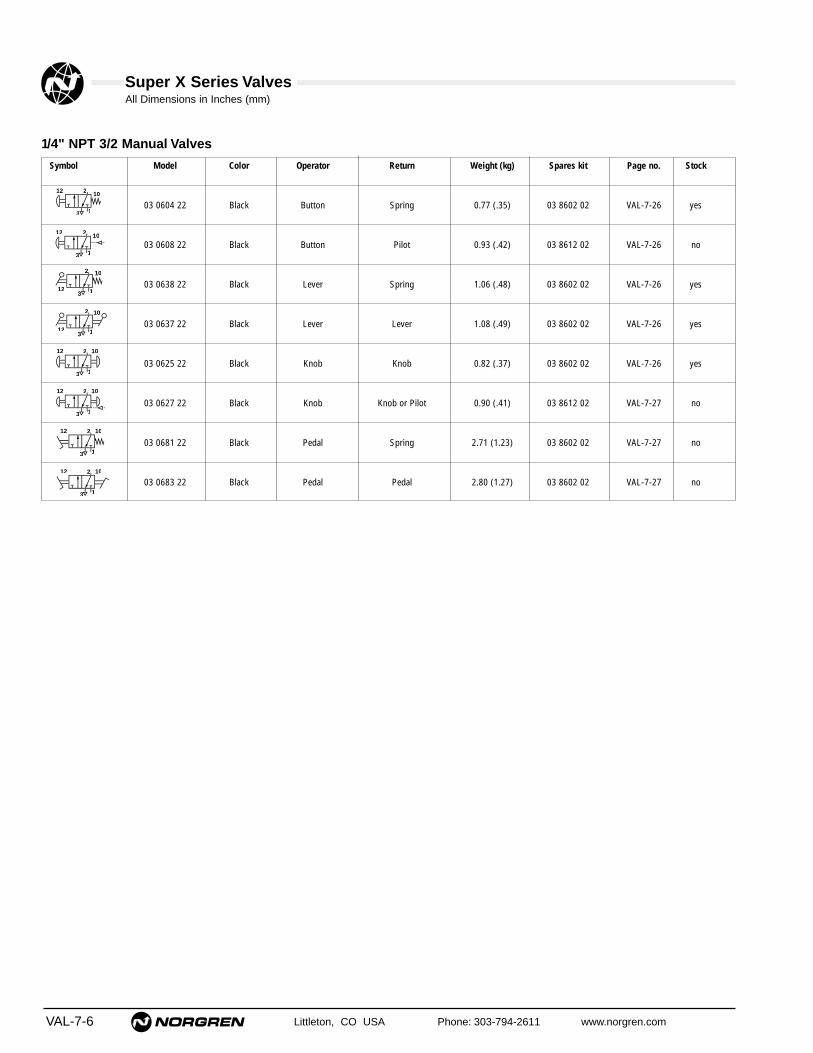
Super X Series ValvesAll Dimensions in Inches (mm)
VAL-7-6 Littleton, CO USA Phone: 303-794-2611 www.norgren.com
Symbol Model Color Operator Return Weight (kg) Spares kit Page no. Stock
03 0604 22 Black Button Spring 0.77 (.35) 03 8602 02 VAL-7-26 yes
03 0608 22 Black Button Pilot 0.93 (.42) 03 8612 02 VAL-7-26 no
03 0638 22 Black Lever Spring 1.06 (.48) 03 8602 02 VAL-7-26 yes
03 0637 22 Black Lever Lever 1.08 (.49) 03 8602 02 VAL-7-26 yes
03 0625 22 Black Knob Knob 0.82 (.37) 03 8602 02 VAL-7-26 yes
03 0627 22 Black Knob Knob or Pilot 0.90 (.41) 03 8612 02 VAL-7-27 no
03 0681 22 Black Pedal Spring 2.71 (1.23) 03 8602 02 VAL-7-27 no
03 0683 22 Black Pedal Pedal 2.80 (1.27) 03 8602 02 VAL-7-27 no
1/4" NPT 3/2 Manual Valves
2
3 13
1012
2
3 13
1012
2
1
10
12
2
112
10
2
3 13
12 10
2
3 13
12 10
2
3 13
12 10
2
3 13
12 10

Super X Series ValvesAll Dimensions in Inches (mm)
Littleton, CO USA Phone: 303-794-2611 www.norgren.com VAL-7-7
Symbol Model Color Operator Mid-position Return Weight lbs. (kg) Spares kit Page no. Stock
X3 0644 22 Black Button - Spring 1.04 (.47) 03 8602 02 VAL-7-28 yes
X3 0648 22 Black Button - Pilot 1.19 (.54) 03 8612 02 VAL-7-28 no
X3 0678 22 Black Lever - Spring 1.32 (.60) 03 8602 02 VAL-7-28 yes
X3 0677 22 Black Lever - Lever 1.35 (.61) 03 8602 02 VAL-7-28 yes
X3 3638 22 Black Lever APB Lever 2.34 (1.06) 03 8602 02 VAL-7-28 yes
X3 3678 22 Black Lever COE Lever 2.34 (1.06) 03 8602 02 VAL-7-28 yes
X3 3637 22 Black Lever APB Lever 1.43 (.65) 03 8602 02 VAL-7-28 yes
X3 3677 22 Black Lever COE Lever 1.43 (.65) 03 8602 02 VAL-7-28 yes
X3 0665 22 Black Knob - Knob 1.08 (.49) 03 8602 02 VAL-7-29 yes
X3 0682 22 Black Pedal - Spring 2.93 (1.33) 03 8602 02 VAL-7-29 no
X3 0684 22 Black Pedal - Pedal 3.06 (1.39) 03 8602 02 VAL-7-29 no
1/4" NPT 5/2 & 5/3 Manual Valves
4 2
5 1 3
1214
4 2
5 1 3
1214
124 2
5 1 314
5 1 3
1214 4 2
5 1 3
1214 4 2
124 2
5 1 3
14
5 1 3
1214 4 2
5 1 3
1214 4 2
124 2
5 1 3
14
124 2
5 1 3
14
124 2
5 1 3
14
APB = All Ports Blocked, COE = Center Open Exhaust.

Super X Series ValvesAll Dimensions in Inches (mm)
VAL-7-8 Littleton, CO USA Phone: 303-794-2611 www.norgren.com
03 0409 221/8" NPT 3/2 Roller Actuated Pilot Return Valve
.75 (19)
‘12’‘2’
‘3’ ‘1’
1.50 (38)
.20 (5)
‘10’
.87 (22)
3.35 (85)
.87
(22)
1.42
(36
)
.18 (5)
1.34 (34)
.83
(21)
.16
(4)
.94 (24)
1/8 NPT
1/8
NP
T
.35 (9)
.47
(12)
.39 (10)
.39 (10)
Operating Force: 4 lbs (18N), ‘10’ at zero barReset Pressure: 30 psi (2 bar) minimumMaximum Recommended Cam Rise: .18" (4.5 mm)Cam Angle of Approach: 30° maximumCam Speed: 26' (8 m)/min. maximumOperating Speed: 300 cpm
03 0400 221/8 NPT 3/2 Plunger Actuated Spring Return Valve
.39 (10)
‘12’‘2’
‘3’ ‘1’
1.50 (38)
.21 (5)
‘10’
.87
(22)
1.42
(36
)
.19 (5) max.
1.28 (33)
.83
(21)
.30
(8)
.67 (17)
3.03 (77)
.35 (9)
1/8 NPT
.39 (10)
.75 (19)
Operating Force: 7 lbs (31N)The plunger on this valve is designed for axial loading only.
03 0417 221/8" NPT 3/2 Plunger Actuated Pilot Return Valve
‘12’‘2’
‘3’ ‘1’
‘10’
3.25
(24
)
.87 (22)
24
3.25 (83)
1.50 (38).19 (5) max.
.39 (10).21 (5)
.87
(22)
1.42
(36
)
1.28 (33)
.30
(8)
1/8 NPT
.75 (19)
.39 (10)
.35 (9)
.83
(21)
1/8
NP
T
Operating Force: 4 lbs (18N), ‘10’ at zero barReset Pressure: 30 lb (2 bar) minimum; Full Movement: 0.19" (4.8mm)The plunger on this valve is designed for axial loading only. This valve can bepanel mounted.Panel Cut-out: Ø.59" (15 mm); Panel thickness: 0.2" (5mm)
03 0402 221/8" NPT 3/2 Roller Actuated Spring Return Valve
.40 (10)
‘12’‘2’
‘3’ ‘1’
.35 (9)
1.50 (38)
.40 (10)
.21 (5)
‘10’
.67 (17)
3.15 (80)
.87
(22)
1.42
(36
)
.18 (5)
.47
(12)
1.34 (34)
.83
(21)
.16
(4)
.75 (19)
1/8 NPT
Operating Force: 7 lbs (31N)Maximum Recommended Cam Rise: .18" (4.5 mm)Cam Angle of Approach: 30° maximumCam Speed: 26' (8 m)/min. maximumOperating Speed: 300 cpm

Super X Series ValvesAll Dimensions in Inches (mm)
Littleton, CO USA Phone: 303-794-2611 www.norgren.com VAL-7-9
03 0293 221/8" NPT 3/2 Heavy Duty Roller Lever ActuatedSpring Return Valve
1.50 (38)
2.87 (73)
'12' '2' '10'
'1''3'
.94
(24)
.98
(25)
1/8 NPT
.31 (8)
1.57 (40)
.22 (6)
Ø.26 (7)
.22
(6)
.04 (1)
.85 (22)
Ø .75 (19)
1.38
(35
)
.79 (20).35 (9)
.67 (17)
.75 (19)
.83
(21)
Operating Force: 4 lbs (18N); Operating Travel: .31" (8 mm)Over-travel: .04" (1mm)Cam Angle of Approach: 45° maximumCam Speed: 26' (8 m)/min. maximumOperating Speed: 300 cpm
03 0423 221/8" NPT 3/2 Sensitive Roller Lever ActuatedSpring Return Valve
.75 (19)
.39 (10)
‘12’‘2’
‘3’ ‘1’
1.50 (38)
.39 (10)
.21 (5)
‘10’
.83
(21)
.33
(9)
.12 (3)
.04 (1)
2.56
(65
)
.87
(22)
1.42
(36
)
2.64 (67)
4.45 (113)
1/8 NPT
1/8 NPT
.35 (9) .67 (17)
.75
(19)
.63
(16)
.71 (18)
Operating Force: .22 lbs (1N)Constant Bleed Pilot Supply: 30 psi (2 bar) minimumPre-travel: .04" (1 mm); Over-travel: .12" (3 mm)Cam Angle of Approach: 45° maximumCam Speed: 21' (6.5 m)/min. maximum
03 0427 221/8" NPT 3/2 Roller Lever Actuated Pilot ReturnValve
.75 (19)
.39 (10)
‘12’‘2’
‘3’ ‘1’
1.50 (38)
.21 (5)
‘10’
.87 (22)
4.13 (105)
.87
(22)
1.42
(36
)
1.18
(30
)
.83
(21)
.12 (3)
.31 (8)
2.32
(59
)
2.13 (54) .94 (24)
1/8 NPT
1/8
NP
T
.39 (10)
.75
(19)
.35 (9)
.33
(9).6
3 (1
6)
Operating Force: 2 lbs (9N), ‘10’ at zero barReset Pressure: 30 lbs (2 bar) minimumOperating travel: 26' (8 mm); Over-travel: .12" (3 mm)Cam Angle of Approach: 45° maximumCam Speed: 26' (8 m)/min. maximumOperating Speed: 300 cpm
03 0411 221/8" NPT 3/2 Roller Lever Actuated Spring Return Valve
.39 (10)
‘12’‘2’
‘3’ ‘1’
1.50 (38)
.39 (10)
.21 (5)
‘10’
.67 (17)
3.94 (100)
.87
(22)
1.42
(36
)
1.18
(30
)
.83
(21)
.35
(9)
.12 (3)
.31 (8)
.75
(19)
2.30
(59
)
2.13 (54)
1/8 NPT
.63
(16)
.75 (19).35 (9)
Operating Force: 4 lbs (18N); Operating Travel: .31" (8 mm)Over-travel: .12" (3 mm)Cam Angle of Approach: 45° maximumCam Speed: 26' (8 m)/min. maximumOperating Speed: 300 cpm

Super X Series ValvesAll Dimensions in Inches (mm)
VAL-7-10 Littleton, CO USA Phone: 303-794-2611 www.norgren.com
03 0410 221/8" NPT 3/2 One-way Trip Actuated Spring ReturnValve
‘12’‘2’
‘3’ ‘1’
1.50 (38)
.21 (5)
‘10’
.67 (17)
1.42
(36
)
2.48 (63)
.83
(21)
.31
(8)
.35 (9)
1.18
(30
)
2.20
(56
)
4.29 (109)
1/8 NPT
.35 (9) .75 (19)
.39 (10).39 (10)
.87
(22)
.63
(16)
Operating Force: 7 lbs (31N)Cam Rise: .35" (9 mm)Cam Angle of Approach: 90° maximumCam Speed: 6.6' (2 m)/min. maximumOperating Speed: 120 cpm
03 0294 221/8" NPT 3/2 Heavy Duty One Way Trip ActuatedSpring Return Valve
'12' '2' '10'
'1''3'
1.50 (38)
2.87 (73)
1.38
(35
)
1.42
(36
)
2.01 (51)
1/8 NPT
Ø.28 (7)
0.22 (6)
.38 (9)
.35 (9)
.67 (17)
.75 (19)
.83
(21)
.79 (20)
Operating Force: 7 lbs (31N)Cam Rise: .35" (9 mm)Cam Angle of Approach: 90° maximumCam Speed: 6.6' (2 m)/min. maximumOperating Speed: 120 cpm
03 0432 221/8" NPT 3/2 Antenna Actuated Spring Return Valve
.75 (19)
.39 (10)
‘12’‘2’
‘3’ ‘1’
1.50 (38)
.39 (10)
0.21 (5)
‘10’
.87
(22)
1.42
(36
)
6.34 (161)
.83
(21)
.51
(13)
.39
(10)
.28 (7)
2.76 (70)
1.73 (44)
1/8 NPT
1/8 NPT
.35 (9) .67 (17)
Operating Force: .06 lbs (0.3N) at tipConstant Pilot Supply: 30 lbs (2 bar) minimumOperating Movement: .40" (10 mm) minimum in any direction.

Super X Series ValvesAll Dimensions in Inches (mm)
Littleton, CO USA Phone: 303-794-2611 www.norgren.com VAL-7-11
X3 0440 221/8" NPT 5/2 Plunger Actuated Spring Return Valve
.87
(22)
1.42
(36
)
.19 (5)
.83
(21)
.30
(8)
.67 (17)
3.91 (100)
.79 (20)
.79(20)
.79(20)
.21 (5)
‘14’‘4’ ‘2’
‘12’
‘5’ ‘1’ ‘3’
2.38 (61)
1.28 (33)
1/8 NPT
.39 (10)
.35 (9)
Operating Force: 12 lbs (54N)Full Movement: .20" (4.8 mm)The plunger on this valve is designed for axial loading only.
X3 0457 221/8" NPT 5/2 Plunger Actuated Pilot Return Valve
.87
(22)
4.11 (105)
.79 (20)
.79(20)
.79(20)
.21 (5)
‘14’‘4’ ‘2’
‘12’
‘5’ ‘1’ ‘3’
2.38 (61)
1.28 (33)
.94
(24)
1.42
(36
)
.19 (5)
.29
(8)
.98 (25)
.87 (22)
1/8 NPT
.35 (9)
.39 (10)
Operating Force: 5 lbs (22N), ‘12’ at zero barReset Pressure: 30 lbs (2 bar) minimum; Full Movement: .20" (4.8 mm)The plunger on this valve is designed for axial mounting only. This valve canbe panel mounted.Panel Cut-out: .59" (.Ø15 mm); Maximum Panel Thickness: .20" (5 mm)
X3 0442 221/8" NPT 5/2 Roller Actuated Spring Return Valve
.67 (17)
4.04 (103)
.79 (20)
.79(20)
.79(20)
.21 (5)
‘14’‘4’ ‘2’
‘12’
‘5’ ‘1’ ‘3’
2.38 (61)
.87
(22)
1.42
(36
)
.18 (5)
.83
(21)
.16
(4)
1.38 (35)
1/8 NPT
.35 (9).47
(12)
.39 (10)
Operating Force: 12 lbs (54N)Maximum Recommended Cam Rise: .20" (4.5 mm)Cam Angle of Approach: 30° maximumCam Speed: 26" (8 m)/min. maximumOperating Speed: 300 cpm
X3 0449 221/8" NPT 5/2 Roller Actuated Pilot Return Valve
.87 (22)
4.23 (108)
.79 (20)
.79(20)
.79(20)
.21 (5)
‘14’‘4’ ‘2’
‘12’
‘5’ ‘1’ ‘3’
2.38 (61)
1.38 (35)
.87
(22)
1.42
(36
)
.18 (5)
.83
(21)
.16
(4)
1/8 NPT1/
8 N
PT
.35 (9).47
(12)
.39 (10)
Operating Force: 5 lbs (22N), ‘12’ at zero barReset Pressure: 30 psi (2 bar) minimumMaximum Recommended Cam Rise: .18" (4.5 mm)Cam Angle of Approach: 30° maximumCam Speed: 26' (8m)/min. maximumOperating Speed: 300 cpm
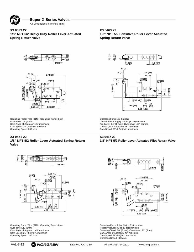
Super X Series ValvesAll Dimensions in Inches (mm)
VAL-7-12 Littleton, CO USA Phone: 303-794-2611 www.norgren.com
.79 (20)
.67(17)
2.36 (60)
3.74 (95)
'5' '1' '3'
'4' '2'
.79(20)
.79(20)
1/8 NPT
.94
(24)
.98
(25)
.31 (8)
'14' '12'
1.57 (40).22 (6)
.22
(6)
.47 (12)
1.38
(35
)
Ø .26 (7)
.04 (1)
.85 (22)Ø.75 (19)
.83
(21)
Operating Force: 7 lbs (31N); Operating Travel: 8 mmOver-travel: .04 (1mm)Cam Angle of Approach: 45° maximumCam Speed: 26' (8m)/min. maximumOperating Speed: 300 cpm
.67 (17)
5.31 (135)
.79 (20)
.79(20)
.79(20)
.21 (5)
‘14’‘4’ ‘2’
‘12’
‘5’ ‘1’ ‘3’
2.38 (61)
.87
(22)
1.42
(36
)
2.68 (68)
.83
(21)
.33
(9)
.12 (3)
.04 (1)
.75
(19)
2.56
(65
)
1/8 NPT
G1/8 NPT
.39 (10)
.35 (9)
.63
(16)
.71 (18)
Operating Force: .23 lbs (1N)Constant Pilot Supply: 44 psi (3 bar) minimumPre-travel: .04" (1 mm); Over-travel: .12" (3 mm)Cam Angle of Approach: 45° maximumCam Speed: 21' (6.5m)/min. maximum
X3 0467 221/8" NPT 5/2 Roller Lever Actuated Pilot Return Valve
.87 (22)
5.02 (128)
.79 (20)
.79(20)
.79(20)
.21 (5)
‘14’‘4’ ‘2’
‘12’
‘5’ ‘1’ ‘3’
2.38 (61)
.87
(22)
1.42
(36
)
1.18
(30
)
.83
(21)
.33
(9)
.12 (3)
.31 (8)
2.32
(59
)
2.17 (55) .98 (25)
1/8 NPT
1/8
NP
T
.75
(19)
.39 (10)
.35 (9)
.63
(16)
Operating Force: 2 lbs (9N), ‘12’ at zero barReset Pressure: 30 psi (2 bar) minimumOperating Travel: 26" (8 mm); Over-travel: .12" (3mm)Cam Angle of Approach: 45° maximumCam Speed: 26' (8m)/min. maximumOperating Speed: 300 cpm
X3 0463 221/8" NPT 5/2 Sensitive Roller Lever ActuatedSpring Return Valve
X3 0393 221/8" NPT 5/2 Heavy Duty Roller Lever ActuatedSpring Return Valve
X3 0451 221/8" NPT 5/2 Roller Lever Actuated Spring ReturnValve
.67 (17)
4.82 (123)
.79 (20)
.35 (9)
.79(20)
.79(20)
.21 (5)
‘14’‘4’ ‘2’
‘12’
‘5’ ‘1’ ‘3’
2.38 (61)
.87
(22)
1.42
(36
)
1.18
(30
)
.83
(21)
.12 (3)
.31 (8)
2.32
(59
)
2.17 (55)
1/8 NPT
.39 (10)
.33
(9)
.63
(16)
.75
(19)
Operating Force: 7 lbs (31N); Operating Travel: 8 mmOver-travel: .12 (3mm)Cam Angle of Approach: 45° maximumCam Speed: 26' (8 m)/min. maximumOperating Speed: 300 cpm
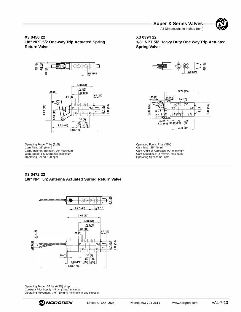
Super X Series ValvesAll Dimensions in Inches (mm)
Littleton, CO USA Phone: 303-794-2611 www.norgren.com VAL-7-13
.67 (17)
5.18 (132)
.79 (20)
.79(20)
.21 (6)
‘14’‘4’ ‘2’
‘12’
‘5’ ‘1’ ‘3’
2.38 (61)
.87
(22)
1.42
(36
)
2.52 (64)
.83
(21)
.31
(8)
.35 (9)
1.18
(30
)
2.20
(56
)
1/8 NPT
.35 (9).79(20)
.39 (10)
.63
(16)
Operating Force: 7 lbs (31N)Cam Rise: .35" (9mm)Cam Angle of Approach: 90° maximumCam Speed: 6.5' (2 m)/min. maximumOperating Speed: 120 cpm
'2'
'1' '3''5'
'4'
2.36 (60)
.79(20)
.79(20)
3.74 (95)
1.42
(36
)
1/8 NPT
2.01 (51)
.35 (9)
'14' '12'
1.38
(35
)
.22 (6)
Ø.26 (7).79 (20)
.75
(19)
.35 (9)
.83
(21)
Operating Force: 7 lbs (31N)Cam Rise: .35" (9mm)Cam Angle of Approach: 90° maximumCam Speed: 6.5' (2 m)/min. maximumOperating Speed: 120 cpm
.67 (17)
7.20 (183)
.79 (20)
.79(20)
.21 (5)
‘14’‘4’ ‘2’
‘12’
‘5’ ‘1’ ‘3’
2.38 (61)
.87
(22)
1.42
(36
)
.51
(13)
.39
(10)
.28 (7)
3.64 (93)
1.77 (45) 1/8 NPT
1/8 NPT
.39 (10)
.35 (9)
.79(20)
.83
(21)
Operating Force: .07 lbs (0.3N) at tipConstant Pilot Supply: 45 psi (3 bar) minimumOperating Movement: .40" (10 mm) minimum in any direction
X3 0450 221/8" NPT 5/2 One-way Trip Actuated SpringReturn Valve
X3 0394 221/8" NPT 5/2 Heavy Duty One Way Trip ActuatedSpring Valve
X3 0472 221/8" NPT 5/2 Antenna Actuated Spring Return Valve

Super X Series ValvesAll Dimensions in Inches (mm)
VAL-7-14 Littleton, CO USA Phone: 303-794-2611 www.norgren.com
03 0600 221/4" NPT 3/2 Plunger Actuated Spring Return Valve
‘1’
‘10’‘2’‘12’
‘3’
.26 (7)
1.69 (43)
.45 (12) .45 (12)
1.10
(28
)
.28 (7)
.94 (24)
.39
(10)
.87 (22)
.87 (22)
.33 (9) max
1.70 (43) max
3.82 (97)
1.18
(30
)
1.85
(47
)
1/4 NPT
.45 (12)
Operating Force: 12 lbs (53N)The plunger on this valve is designed for axial loading only.
03 0602 221/4" NPT 3/2 Roller Actuated Spring Return Valve
‘1’
‘10’‘2’‘12’
‘3’
.26 (7)
1.69 (43)
.45 (12) .45 (12)
.87 (22)
.87 (22)
4.33 (110)
1.18
(30
)
1.85
(47
)
.75
(19)
.31 (8)
1.10
(28
)
.30
(8)
1/4 NPT
.45 (12)
Operating Force: 14 lbs (61N)Cam Angle of Approach: 45° maximumCam Speed: 20' (6 m)/min. maximumOperating Speed: 200 cpm
03 0609 221/4" NPT 3/2 Roller Actuated Pilot Return Valve
‘1’
‘10’‘2’‘12’
‘3’
.26 (7)
1.69 (43)
.45 (12) .45 (12)
1.22 (31)
4.65 (118)
.75
(19)
.31 (8)
1.10
(28
)
.30
(8)
1.18
(30
)
1.85
(47
)
1/4 NPT
1/8
NP
T
.45 (12)
Operating Force: 3 lbs (13N), ‘10’ at zero barReset Pressure: 30 psi (2 bar) minimumCam Angle of Approach: 45° maximumCam Speed: 20' (6 m)/min. maximumOperating Speed: 200 cpm
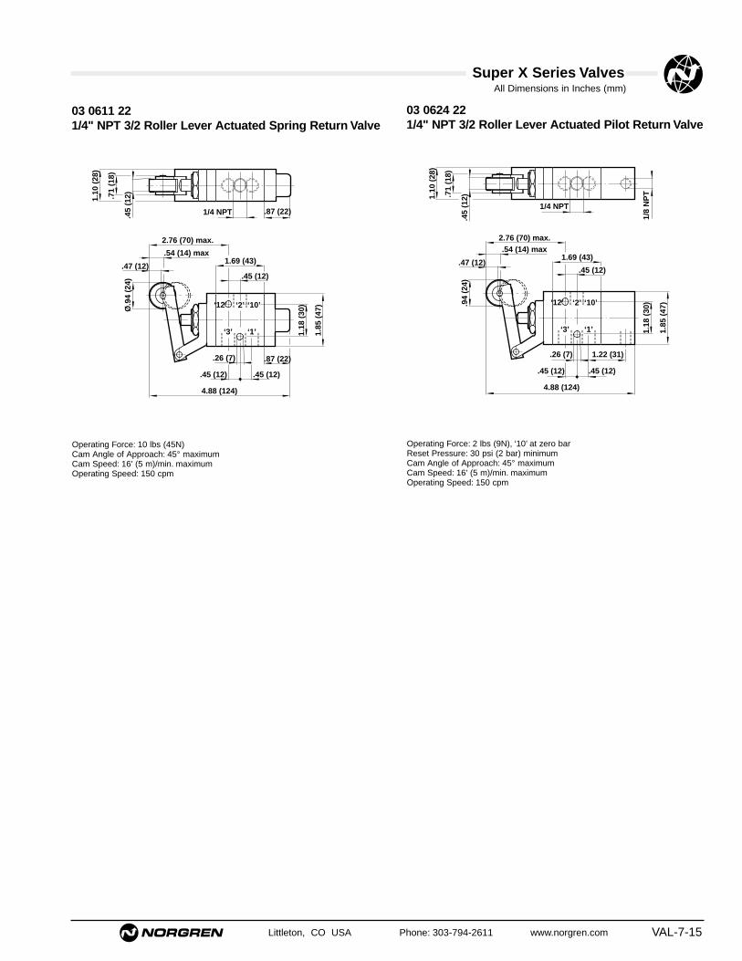
Super X Series ValvesAll Dimensions in Inches (mm)
Littleton, CO USA Phone: 303-794-2611 www.norgren.com VAL-7-15
03 0624 221/4" NPT 3/2 Roller Lever Actuated Pilot Return Valve
‘1’
‘10’‘2’‘12’
‘3’
.26 (7)
1.69 (43)
.45 (12) .45 (12)
1.22 (31)
4.88 (124)
1.18
(30
)
1.85
(47
).94
(24)
.47 (12)
.54 (14) max2.76 (70) max.
1.10
(28
)
.71
(18)
1/4 NPT
1/8
NP
T
.45 (12)
.45
(12)
Operating Force: 2 lbs (9N), ‘10’ at zero barReset Pressure: 30 psi (2 bar) minimumCam Angle of Approach: 45° maximumCam Speed: 16' (5 m)/min. maximumOperating Speed: 150 cpm
03 0611 221/4" NPT 3/2 Roller Lever Actuated Spring Return Valve
‘1’
‘10’‘2’‘12’
‘3’
.26 (7)
1.69 (43)
.45 (12) .45 (12)
.87 (22)
.87 (22)
4.88 (124)
1.18
(30
)
1.85
(47
)Ø.9
4 (2
4)
.47 (12)
.54 (14) max
2.76 (70) max.
1.10
(28
)
.71
(18)
1/4 NPT
.45 (12)
.45
(12)
Operating Force: 10 lbs (45N)Cam Angle of Approach: 45° maximumCam Speed: 16' (5 m)/min. maximumOperating Speed: 150 cpm

Super X Series ValvesAll Dimensions in Inches (mm)
VAL-7-16 Littleton, CO USA Phone: 303-794-2611 www.norgren.com
X3 0640 221/4" NPT 5/2 Plunger Actuated Spring Return Valve
‘14’ ‘4’ ‘2’ ‘12’
‘5’ ‘1’ ‘3’
.45 (12) .91 (23)
.26 (7)
2.56 (65)
.91(23)
1.10
(28
)
.28 (7)
.94 (24)
.39
(10)
.31 (8) max.
1.65 (42)
.87 (22)
4.69 (119)
1.18
(30
)
1.85
(47
)
.87 (22)1/4 NPT
.45 (12)
.91(23)
Operating Force: 14 lbs (62N)The plunger on this valve is designed for axial loading only.
X3 0642 221/4" NPT 5/2 Roller Actuated Spring Return Valve
‘14’ ‘4’ ‘2’ ‘12’
‘5’ ‘1’ ‘3’
.45 (12) .91 (23)
.26 (7)
2.56 (65)
.91(23)
.87 (22)
5.20 (132)
1.18
(30
)
1.85
(47
)
.87 (22)
.75
(19)
.31 (8)
1.10
(28
)
.30
(8)
1/4 NPT
.45 (12)
.91(23)
Operating Force: 15 lbs (67N)Cam Angle of Approach: 45° maximumCam Speed: 20' (6 m)/min. maximumOperating Speed: 200 cpm
X3 0649 221/4" NPT 5/2 Roller Actuated Pilot Return Valve
‘14’ ‘4’ ‘2’ ‘12’
‘5’ ‘1’ ‘3’
.45 (12) .91 (23)
.26 (7)
2.56 (65)
.91(23)
.91(23)
5.51 (140)
1.18
(30
)
1.85
(47
)
.75
(19)
.31 (8)
1.10
(28
)
.30
(8)
1/4 NPT
1/8
NP
T
.45 (12)
Operating Force: 3 lbs (13N), ‘12’ at zero barReset Pressure: 30 psi (2 bar) minimumCam Angle of Approach: 45° maximumCam Speed: 20' (6 m)/min. maximumOperating Speed: 200 cpm
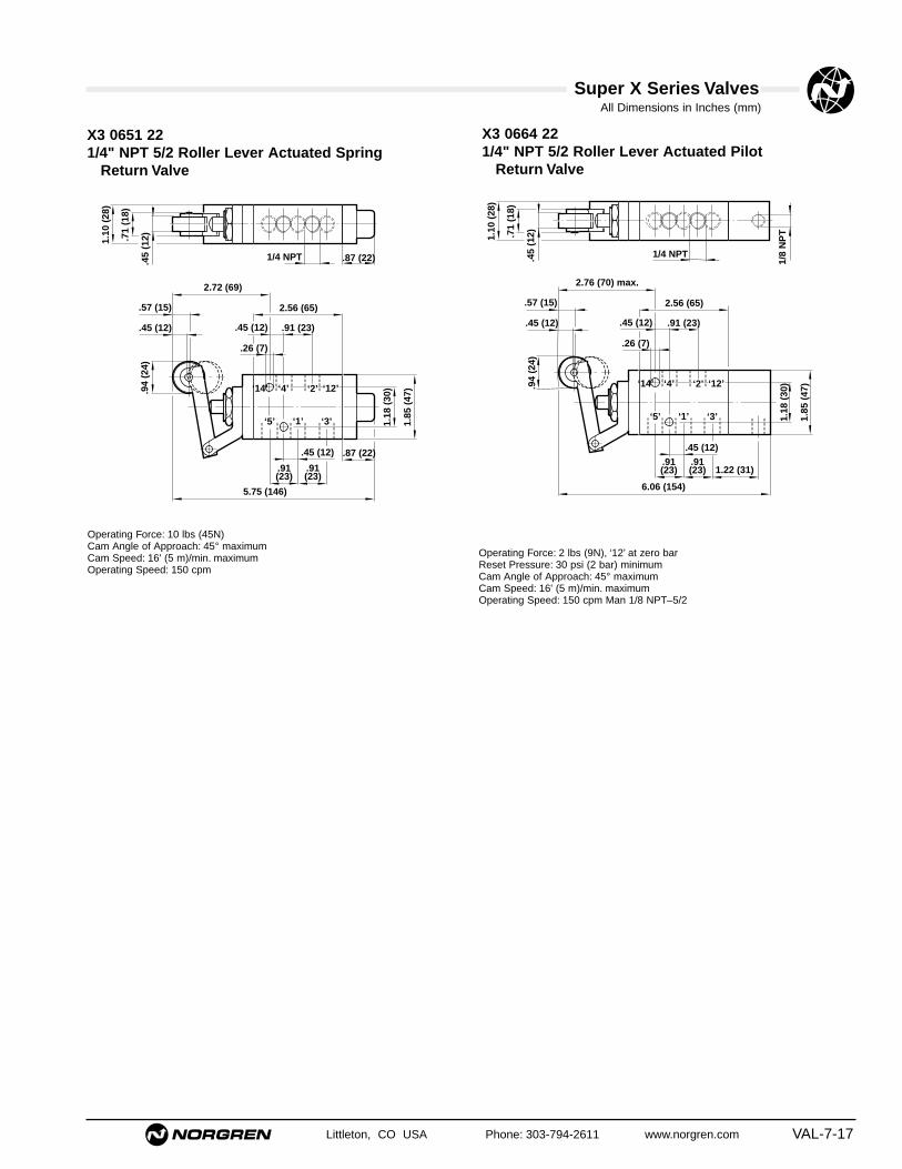
Super X Series ValvesAll Dimensions in Inches (mm)
Littleton, CO USA Phone: 303-794-2611 www.norgren.com VAL-7-17
X3 0664 221/4" NPT 5/2 Roller Lever Actuated Pilot
Return Valve
‘14’ ‘4’ ‘2’ ‘12’
‘5’ ‘1’ ‘3’
.45 (12) .91 (23)
.26 (7)
2.56 (65)
.91(23)
.91(23)
6.06 (154)
.94
(24)
.45 (12)
.57 (15)
2.76 (70) max.
1.10
(28
)
.71
(18)
1.18
(30
)
1.85
(47
)
1.22 (31)
1/4 NPT
1/8
NP
T
.45 (12)
.45
(12)
Operating Force: 2 lbs (9N), ‘12’ at zero barReset Pressure: 30 psi (2 bar) minimumCam Angle of Approach: 45° maximumCam Speed: 16' (5 m)/min. maximumOperating Speed: 150 cpm Man 1/8 NPT–5/2
X3 0651 221/4" NPT 5/2 Roller Lever Actuated Spring
Return Valve
‘14’ ‘4’ ‘2’ ‘12’
‘5’ ‘1’ ‘3’
.45 (12) .91 (23)
.26 (7)
2.56 (65)
.91(23)
.87 (22)
5.75 (146)
1.18
(30
)
1.85
(47
)
.87 (22)
.94
(24)
.45 (12)
.57 (15)
2.72 (69)
1.10
(28
)
.71
(18)
1/4 NPT
.45 (12)
.91(23)
.45
(12)
Operating Force: 10 lbs (45N)Cam Angle of Approach: 45° maximumCam Speed: 16' (5 m)/min. maximumOperating Speed: 150 cpm

All Dimensions in Inches (mm)
VAL-7-18 Littleton, CO USA Phone: 303-794-2611 www.norgren.com
Operating Force: 7 lbs (31N)These valves are suitable for panel mounting.Panel Hole: Ø1.22" (31 mm); Panel Thickness: .39" (10 mm) maximumReplacement Button Red - part number: 03041661
Green - part number: 03041561Black - part number: 03041463
03 0404 221/8" NPT 3/2 Button Operated Spring Return Valve
1.18
(30
).7
5 (1
9)
.94
(24)
.19 (5) .75 (19)
.39 (10)
‘12’‘2’
‘3’ ‘1’
1.50 (38)
.39 (10)
.21 (5)
‘10’
1/8 NPT
.67 (17)
.87
(22)
1.42
(36
)
3.50 (89)
.35 (9)
.20 (5) max.
.83
(21)
Operating Force: 7 lbs (31N)These valves are suitable for panel mounting by means of an optional nutand washer, reference 03 0430 00; a shrouded panel mounting kit is alsoavailable, reference 03 0429 00.Panel Hole: Ø.59" (15 mm); Panel Thickness: .2 (5 mm) maximumReplacement Button Red - part number: 03040965
Green - part number: 03040865Black - part number: 03040765
.75 (19)
‘12’‘2’
‘3’ ‘1’
1.50 (38)
.39 (10)
.21 (5)
‘10’
.67 (17)
.87
(22)
1.42
(36
)
2.48 (63)
.79 (20)
4.17 (106)
1.50
(38
)
1/8 NPT
.39 (10)
.83
(21)
.35 (9)
Operating Force: 7 lbs (31N)These valves are suitable for panel mounting.Panel Hole: Ø1.26" (32.1 mm); Panel Thickness: .24" (6 mm) maximum
03 0408 22, 03 0420 22, 03 0421 22 Models1/8" NPT 3/2 Button Operated Pilot Return Valve
1.18
(30
)
.94
(24)
.19 (5) .75 (19)
.39 (10)
‘12’‘2’
‘3’ ‘1’
1.50 (38)
.39 (10)
.21 (5)
‘10’
.87 (22)
.87
(22)
1.42
(36
)
3.70 (94)
.94 (24)
1/8 NPT
.20 (5) max.
1/8
NP
T .83
(21)
.75
(19)
A/F
.35 (9)
Operating Force: 4 lbs (18N), pilot port ‘10’ at zero barReset Pressure: 30 psi (2 bar) minimumThese valves are suitable for panel mounting by means of an optional nutand washer, reference 03 0430 00; a shrouded panel mounting kit is alsoavailable, reference 03 0429 00.Panel Hole: Ø.59" (15 mm); Panel Thickness: .20" (5 mm) maximum
03 0366 22, 03 0367 22, 03 0368 22 Models1/8" NPT 3/2 Button (Palm) Operated SpringReturn Valves
1.34
(34
)
.39 (10) max.
.75 (19)
.39 (10)
‘12’‘2’
‘3’ ‘1’
1.50 (38)
.39 (10)
.21 (5)
‘10’
.67 (17)
.87
(22)
1.42
(36
)
3.13 (80)
1/8 NPT
.83
(21)
.35 (9)
03 0414 221/8" NPT 3/2 Button (Shrouded) Operated SpringReturn Valve
Super X Series Valves

Super X Series ValvesAll Dimensions in Inches (mm)
Littleton, CO USA Phone: 303-794-2611 www.norgren.com VAL-7-19
03 0428 221/8" NPT 3/2 Palm Button Operated, Twist ReturnValve (Emergency Stop)
.75 (19)
‘12’‘2’
‘3’ ‘1’
1.50 (38)
.39 (10)
.21 (5)
‘10’
.67 (17).8
7 (2
2)
1.42
(36
)
2.48 (63)
.79 (20)
4.53 (115)
1.50
(38
)
.20 (5)
1/8 NPT
.39 (10)
.35 (9).8
3 (2
1)
Operating Force: 4 lbs (18N)Valve latches when button is depressed and returns when the locking ring isrotated anti-clockwise.This valve is suitable for panel mounting.Panel Hole: 1.26" (32.1 mm); Panel Thickness: .31" (8 mm) maximum
03 0296 221/8" NPT 3/2 Lever Operated Lever Return Valve
.35 (9)
1.50 (38)
.87
(22)
.39 (10)
1.06 (27)
1.54 (39)
R 4
7
3.23 (82)
‘2’
‘3’ ‘1’
‘12’ ‘10’
1/8 NPT
.67 (17)
.83
(21)
.75 (19)
Operating Force: 3 lbs (13N)This valve is suitable for panel mounting.Panel Hole: .89" (22.5 mm); Panel Thickness: .24 (6 mm) maximum
03 0335 221/8" NPT 3/2 Button (Palm) Operated Key Return Valve
.75 (19)
‘12’‘2’
‘3’ ‘1’
1.50 (38)
.39 (10)
.21 (5)
‘10’
.67 (17)
.87
(22)
1.42
(36
)
2.48 (63)
.79 (20)
4.49 (114)
1.50
(38
)
1/8 NPT
.39 (10)
.35 (9)
.83
(21)
Operating Force: 7 lbs (31N)Valve latches when button is depressed. To reset, turn key. This valve is suitable for panel mounting.Panel Hole: 1.26" (32.1 mm); Panel Thickness: .24" (6mm) maximum
03 0403 221/8" NPT 3/2 Lever Operated Spring Return Valve
.94
(24)
.75 (19)
.39 (10)
‘12’‘2’
‘3’ ‘1’
1.50 (38)
.39 (10)
.21 (5)
‘10’
.67 (17)
.87
(22)
1.42
(36
)
3.50 (89)
90°
1/8 NPT
.35 (9)
.20 (5)max.
.83
(21)
.75
(19)
A/F
Operating Force: 6 lbs (28N)This valve is suitable for panel mounting. A fingertip extension is availablefor this valve, reference 07 0033 01.Panel Hole: Ø.59" (15 mm); Panel Thickness: .20 (5 mm) maximum

Super X Series Valves
VAL-7-20 Littleton, CO USA Phone: 303-794-2611 www.norgren.com
All Dimensions in Inches (mm)
03 0438 22 & 03 0437 22 Models1/8" NPT 3/2 Lever Operated Spring Return Valves
.75 (19)
.39 (10)
‘12’‘2’
‘3’ ‘1’
1.50 (38)
.39 (10)
.21 (5)
‘10’
.67 (17)
.87
(22)
1.42
(36
)
3.66
(93
)
M4x0,7
3.07 (78)
1/8 NPT
.83
(21)
.35 (9)
.83 (21)
Operating Force: 2 lbs (9N)Model 03 0437 22 features a positive detent in each position and is suitablefor panel mounting by means of a bezel kit, reference 03 3437 64.Panel Hole: Ø.94" (24 mm)Panel Thickness: .31" (8 mm) maximum
03 0425 221/8" NPT 3/2 Knob Operated Knob Return Valve
.75 (19)
.39 (10)
‘12’‘2’
‘3’ ‘1’
1.50 (38)
.39 (10)
.21 (5)
‘10’
.67 (17)
.87
(22)
1.42
(36
)
3.82 (97)
.87
(22)
.19 (5)
.94
(24)
1/8 NPT
.20 (5) max.
.83
(21)
.75
(19)
A/F
.35 (9)
Operating Force: 4 lbs (18N)This valve is suitable for panel mounting by means of an optional nut andwasher, reference 03 0430 00.Panel Hole: Ø.59" (15 mm); Panel Thickness:.20" (5 mm) maximumReplacement Button Red - part number: 03046463
Black - part number: 03046462
03 0419 221/8" NPT 3/2 Rotary Knob Operated Rotary KnobReturn Valve
.75 (19)
.39 (10)
‘12’‘2’
‘3’ ‘1’
1.50 (38)
.39 (10)
.21 (5)
‘10’
.67 (17)
.87
(22)
1.42
(36
)
3.09 (79)
1.34 (34)
1.06
(27
)
1.63
(41
)
45°
4.44 (113)
1.32 (34)
45°
1/8 NPT
.83
(21)
.35 (9)
Switch shown in non-operated positionThis valve is suitable for panel mounting.Panel Hole: Ø1.26" (32.1mm); Panel Thickness: .24" (6mm) maximum
03 0424 221/8" NPT 3/2 Knob Operated, Knob or Pilot ReturnValve
.75 (19)
.39 (10)
‘12’‘2’
‘3’ ‘1’
1.50 (38)
.39 (10)
.21 (5)
‘10’
.87 (22)
.87
(22)
1.42
(36
)
4.02 (102)
22
.19 (5)
.94
(24)
.94 (24)
1/8 NPT
1/8
NP
T
.20 (5) max.
.35 (9)
.83
(21)
.75
(19)
A/F
Operating Force: 4 lbs (18N)Reset Pressure: 30 psi (2 bar) minimumThis valve is suitable for panel mounting by means of an optional nut andwasher, reference 03 0430 00.Panel Hole: Ø.59" (15 mm); Panel Thickness: .20" (5 mm) maximum

Super X Series ValvesAll Dimensions in Inches (mm)
Littleton, CO USA Phone: 303-794-2611 www.norgren.com VAL-7-21
03 0418 22 8011/8" NPT 3/2 Key Operated Key Return Valve
.75 (19)
.39 (10)
‘12’‘2’
‘3’ ‘1’
1.50 (38)
.39 (10)
.21 (5)
‘10’
.67 (17)
.87
(22)
1.42
(36
)
3.09 (79)
1.56 (40)
4.66 (118)
1.32 (34)
1.19
(30
)
.94 (24)45° 45°
1/8 NPT
.35 (9)
.83
(21)
The key is removable in both positions. Key slot shown in non-operatedposition. Two keys are supplied.This valve is suitable for panel mounting.Panel Hole: Ø1.26" (32.1 mm)Panel Thickness: .24" (6 mm) maximum
03 0481 221/8" NPT 3/2 Pedal Operated Spring Return Valve
2.68
(68
)
7.36 (187)
5°
2.80
(71
)
3.94 (100)2.56 (65)
2.68 (68)
2.36
(60
)
.26 (7)
.47
(12)
.47
(12)
1/8 NPT
Operating Force: 5 lbs (22N)A foot guard is available for this valve, reference 03 0480 60.
03 0483 221/8" NPT 3/2 Pedal Operated Pedal Return Valve
2.68
(68
)
7.36 (187)
5°
2.80
(71
)
3.94 (100)2.56 (65)
2.68 (68)
2.36
(60
)
.26 (7)
.47
(12)
.47
(12)
1/8 NPT
Operating Force: 5 lbs (22N)A foot guard is available for this valve, reference 03 0480 60.

Super X Series ValvesAll Dimensions in Inches (mm)
VAL-7-22 Littleton, CO USA Phone: 303-794-2611 www.norgren.com
.79 (20)
.79(20)
.21 (5)
‘14’‘4’ ‘2’
‘12’
‘5’ ‘1’ ‘3’
2.38 (61)
1.18
(30
)
.94
)24)
.79 (5) .67 (17)
1.73 (44)
4.39 (112)
.87
(22)
1.42
(36
)
1/8 NPT
.39 (10)
.20 (5) max. .35 (9).79(20)
.83
(21)
.75
(19)
A/F
Operating Force: 12 lbs (54N)These valves are suitable for panel mounting by means of an optional nutand washer, reference 03 0430 00; a shrouded panel mounting kit is alsoavailable, reference 03 0429 00.Panel Hole: Ø.59" (15 mm); Panel Thickness: .20" (5mm) maximumReplacement Button Red - part number: 03040965
Green - part number: 03040865Black - part number: 03040765
X3 0386 22, X3 0387 22, X3 0388 221/8" NPT 5/2 Button (Palm) Operated SpringReturn Valves
.79 (20)
.79(20)
.79(20)
.21 (5)
‘14’‘4’ ‘2’
‘12’
‘5’ ‘1’ ‘3’
2.38 (61)
.67 (17)
3.43 (87)
.87
(22)
1.42
(36
)
1.50
(38
)5.12 (130)
1/8 NPT
.39 (10)
.35 (9)
.83
(21)
Operating Force: 7 lbs (31N)These valves are suitable for panel mounting.Panel Hole: Ø1.26" (32.1 mm)Panel Thickness: .24" (6 mm) maximum
.79 (20)
.79(20)
.79(20)
.21 (5)
‘14’‘4’ ‘2’
‘12’
‘5’ ‘1’ ‘3’
2.38 (61)
30
.94
(24)
.19 (5)
1.73 (44)
4.59 (117)
.87
(22)
1.42
(36
).8
3 (2
1)
.98 (25)
.87 (22)
1/8 NPT
1/8
NP
T
.20 (5) max. .35 (9)
.39 (10)
.75
(19)
A/F
Operating Force: 5 lbs (22N), pilot port ‘12’ at zero barReset Pressure: 30 psi (2 bar) minimumThese valves are suitable for panel mounting by means of an optional nutand washer, reference 03 0430 00; a shrouded panel mounting kit is alsoavailable, reference 03 0429 00.Panel Hole: Ø.59" (15 mm); Panel Thickness: .20" (5 mm) maximum
X3 0444 221/8" NPT 5/2 Button (Palm) Operated SpringReturn Valves
X3 0454 22, X3 0455 22, X3 0456 221/8" NPT 5/2 Button (Shrouded) Operated SpringReturn Valves
.79 (20)
.79(20)
.79(20)
‘14’‘4’ ‘2’
‘12’
‘5’ ‘1’ ‘3’
2.38 (61)
.67 (17)
1.36 (35)
4.02 (102)
.87
(22)
1.42
(36
)
1.34
(34
)
.39 (10) max.1/8 NPT
.35 (9)
.21 (5)
.39 (10)
.83
(21)
Operating Force: 12 lbs (54N)These valves are suitable for panel mounting.Panel Hole: Ø1.22" (31 mm)Panel Thickness: .39" (10 mm maximum)Replacement Button Red - part number: 03041661
Green - part number: 03041561Black - part number: 03041463
X3 0448 22, X3 0460 22, X3 0461 221/8" NPT 5/2 Button (Palm) Operated Pilot ReturnValves

Super X Series ValvesAll Dimensions in Inches (mm)
Littleton, CO USA Phone: 303-794-2611 www.norgren.com VAL-7-23
X3 0443 221/8" NPT 5/2 Lever Operated Spring Return Valve
.79 (20)
.79(20)
.79(20)
‘14’‘4’ ‘2’
‘12’
‘5’ ‘1’ ‘3’
2.38 (61)
.67 (17)
1.87 (48)
.87
(22)
1.42
(36
)
4.53 (115)
90°
.94
(24)
1/8 NPT
.21 (5)
.39 (10)
.20 (5) max. .34 (9)
.83
(21)
.75
(19)
A/F
Operating Force: 11 lbs (48N)This valve is suitable for panel mounting. A fingertip extension is availablefor use on this valve, reference07 0033 01.Panel Hole: Ø.59" (15 mm); Panel thickness: .20" (5 mm) maximum
X3 0468 221/8" NPT 5/2 Button (Palm) Operated Twist ReturnValve (Emergency Stop)
.79(20)
.79(20)
.79(20)
.21 (5)
‘14’‘4’ ‘2’
‘12’
‘5’ ‘1’ ‘3’
.39(10)
2.38 (61)
.67 (17)
3.43 (87)
.87
(22)
1.42
(36
)
5.41 (138)
1.50
(38
)
.20 (5)
.79(20)
1/8 NPT
.35 (9)
.83
(21)
Operating Force: 4 lbs (18N)Valve latches when button is depressed and returns when the locking ring isrotated anti-clockwise.This valve is suitable for panel mounting.Panel Hole: Ø1.26" (32.1 mm); Panel thickness: .31" (8mm) maximum
X3 0375 221/8" NPT 5/2 Button (Palm) Operated Key Return Valve
.79(20)
.79(20)
.79(20)
.21 (5)
‘14’‘4’ ‘2’
‘12’
‘5’ ‘1’ ‘3’
.39(10)
2.38 (61)
.67 (17)
3.43 (87)
.87
(22)
1.42
(36
)
5.43 (138)
.79(20)
1.50
(38
)
1/8 NPT
.35 (9)
.83
(21)
Operating Force: 12 lbs (54N)Valve latches when button is depressed. To reset, turn key. This valve issuitable for panel mounting.Panel Hole: Ø1.26" (32.1 mm)Panel Thickness: .24" (6 mm) maximum
X3 0296 221/8" NPT 5/2 Lever Operated Lever Return Valve
.83
(21)
1.54 (39)
3.23 (82)
R 4
7
.67(17)
.87
(22)
2.36 (60)
.79(20)
.79(20).47 (12)
.79(20)
.39 (10)
.35(9)1.06 (27)
1/8 NPT
‘14’‘4’ ‘2’
‘12’
‘5’ ‘1’ ‘3’
Operating Force: 3 lbs (13N)This valve is suitable for panel mounting.Panel Hole: .89" (22.5 mm); Panel Thickness: .24" (6 mm) maximum

Super X Series ValvesAll Dimensions in Inches (mm)
VAL-7-24 Littleton, CO USA Phone: 303-794-2611 www.norgren.com
X3 0464 221/8" NPT 5/2 Knob Operated, Knob or Pilot ReturnValve
.79 (20)
.79(20)
.79(20)
.21 (5)
‘14’‘4’ ‘2’
‘12’
‘5’ ‘1’ ‘3’
.39 (10)
2.38 (61)
.87 (22)
2.05 (52)
.87
(22)
1.42
(36
)
4.90 (125)
.87
(22)
.19 (5)
.94
(24)
.83
(21)
1/8 NPT
1/8
NP
T
.35 (9).20 (5 )max.
.75
(19)
A/F
Operating Force: 5 lbs (22N)Reset Pressure: 30 psi (2 bar) minimumThis valve is suitable for panel mounting by means of an optional nut andwasher, reference 03 0430 00.Panel Hole: Ø.59" (15 mm)Panel thickness: .20" (5mm) maximum
X3 0478 22, X3 0477 221/8" NPT 5/2 Lever Operated Valves
.79 (20)
.79(20)
.79(20)
.21 (5)
‘14’‘4’ ‘2’
‘12’
‘5’ ‘1’ ‘3’
2.38 (61)
.67 (17)
.87
(22)
1.42
(36
)
3.66
(93
)
M4x0,7
3.94 (100)
1/8 NPT
.83
(21)
.35 (9)
.39 (10)
.83 (21)
Operating Force: X3 0478 22 = 3.6 lbs (16N) X3 0477 22 = 3 lbs (13N)
Both models are suitable for panel mounting by means of a bezel kit, reference 03 3437 64.Panel Hole: Ø.94" (24 mm); Panel Thickness: .31" (8 mm) maximum
X3 3438 22, X3 3478 22, X3 3437 22, X3 3477 22 1/8"NPT 5/2 Three Position Lever Operated Valves
.79 (20)
.79(20)
.79(20)
.21 (5)
‘14’‘4’ ‘2’
‘12’
‘5’ ‘1’ ‘3’
2.38 (61)
.87
(22)
1.42
(36
)
3.70
(94
)
M4x0,7
.69 (18) .69 (18)
3.19 (81)
1.36 (35) .98 (25)
1/8 NPT
.83
(21)
.35 (9)
.39 (10)
.83 (21)
Operating Force: X3 3438 22 and X3 3478 22 = 3.4 lbs (15N)X3 3437 22 and X3 3477 22 = 3 lbs (12N)
All models are suitable for panel mounting, by means of a bezel kit, reference 03 3437 64.Panel Hole: Ø.94" (24 mm); Panel Thickness: .31" (8mm) maximum
X3 0465 221/8" NPT 5/2 Knob Operated Knob Return Valve
.79 (20)
.79(20)
.79(20)
.21 (5)
‘14’‘4’ ‘2’
‘12’
‘5’ ‘1’ ‘3’
.39 (10)
2.38 (61)
.67 (17)
2.05 (52)
.87
(22)
1.42
(36
)
4.70 (120)
22
.19 (5)
.94
(24)
1/8 NPT
.20 (5) max..35 (9)
.75
(19)
A/F
.83
(21)
Operating Force: 5 lbs (22N)This valve is suitable for panel mounting by means of an optional nut andwasher, reference 03 0430 00.Panel Hole: Ø.59" (15 mm)Panel thickness: .20" (5mm) maximum

Super X Series ValvesAll Dimensions in Inches (mm)
Littleton, CO USA Phone: 303-794-2611 www.norgren.com VAL-7-25
X3 0459 221/8" NPT 5/2 Rotary Knob Operated Knob Return Valve
.79(20)
.79(20)
.79(20)
.21 (5)
‘14’‘4’ ‘2’
‘12’
‘5’ ‘1’ ‘3’
.39(10)
2.38 (61)
.67 (17)
1.34 (34) 1.32 (34)
1.06
(27
)
1.63
(41
)
45°
.87
(22)
1.42
(36
)
3.98 (101)
5.31 (135)
45°
1/8 NPT
.35 (9)
.83
(21)
Switch shown in non-operated position.This valve is suitable for panel mounting.Panel Hole: Ø1.26" (32 mm); Panel Thickness: .24" (6 mm) maximum
X3 0458 22 8011/8" NPT 5/2 Key Operated Key Return Valve
1.57 (40).79(20)
.79(20)
.79(20)
.21 (5)
‘14’‘4’ ‘2’
‘12’
‘5’ ‘1’ ‘3’
.39(10)
2.38 (61)
.67 (17)
1.32 (34)
.87
(22)
1.42
(36
)
3.98 (101)
5.55 (141)1.
19 (
31)
.94 (24)45° 45°
1/8 NPT
.35 (9)
.83
(21)
The key is removable in both positions. Key slot shown in non-operated position. Two keys are supplied.This valve is suitable for panel mounting.Panel Hole: Ø1.26" (32 mm); Panel Thickness: .24" (6 mm) maximum
X3 0482 221/8" NPT 5/2 Pedal Operated Spring Return Valve
2.68
(68
)
7.36 (187)
5°
2.80
(71
)
3.94 (100)2.56 (65)
2.56 (65)
2.36
(60
)
.26 (7)
.47
(12)
.47
(12)
1/8 NPT
Operating Force: 5 lbs (22N)A foot guard is available for this valve, reference03 0480 60.
X3 0484 221/8" NPT 5/2 Pedal Operated Pedal Return Valve
2.68
(68
)7.36 (187)
5°
2.80
(71
)
3.94 (100)2.56 (65)
2.56 (65)
2.36
(60
)
.26 (7)
.47
(12)
.47
(12)
1/8 NPT
Operating Force: 5 lbs (22N)A foot guard is available for this valve, reference03 0480 60.

Super X Series ValvesAll Dimensions in Inches (mm)
VAL-7-26 Littleton, CO USA Phone: 303-794-2611 www.norgren.com
03 0638 22, 03 0637 221/4" NPT 3/2 Lever Operated Valves
‘14’ ‘4’ ‘2’ ‘12’
‘5’ ‘1’ ‘3’
.45 (12) .91 (23)
Ø.26 (7)
2.56 (65)
.91(23)
.91(23)
1.18
(30
)
1.85
(47
)
52
M5x0,8
.93(24)
1.10
(28
)
1.89 (48) .87 (22)
1/4 NPT5.28
(13
4)
.45 (12)
Operating Force: 03 0638 22 = 5 lbs (15N)03 0637 22 = 3 lbs (13N)
Model 03 0637 02 features a positive detent in each position.Both Models are suitable for panel mounting by means of a bezel kit, reference 03 3637 64.Panel Hole: Ø1.22" (31 mm);Panel Thickness: .31" (8 mm) maximum
03 0608 221/4" NPT 3/2 Button Operated Pilot Return Valve
‘1’
‘10’‘2’‘12’
‘3’
.26 (7)
1.69 (43)
.45 (12)1.
61 (
41)
1.91 (50) max.5.12 (130) max.
1.10
(28
)
1.20 (31)
1.18
(30
)
1.85
(47
)
1/4 NPT
.45 (12)
1.57 (40) min.
.45 (12)
1/4
NP
T
Operating Force: 3 lbs (13N), pilot port ‘10’ at zero barReset Pressure: 30 psi (2 bar) minimumThis valve is suitable for panel mounting and includes a nut and washer.Panel Hole: Ø.83 (21 mm); Panel thickness: .31 (8 mm) maximum
03 0604 221/4" NPT 3/2 Button Operated Spring Return Valve
‘1’
‘10’‘2’‘12’
‘3’
.26 (7)
1.69 (43)
.45 (12)
1.61
(41
)
1.91 (49) max.4.80 (122) max.
1.10
(28
)1.
18 (
30)
1.85
(47
)
.87 (22)
2.62 (67) max.
1/4 NPT
1.57 (40) min.
.45 (12)
.45 (12)
Operating Force: 12lbs (53N)This valve is suitable for panel mounting and includes a nut and washer.Panel Hole: Ø.83" (21 mm); Panel Thickness: .31" (8 mm) maximum
03 0625 221/4" NPT 3/2 Knob Operated Knob Return Valve
‘1’
‘10’‘2’‘12’
‘3’
.26 (7)
1.69 (43)
.45 (12)
1.10
(28
)1.
18 (
30)
1.85
(47
)
.87 (22)
.28 (7)
2.30 (59)
5.18 (132)
3.01 (77)
1/4 NPT
.45 (12)
.45 (12)
Operating Force: 3 lbs (13N)This valve is suitable for panel mounting and includes a nut and washer.Panel Hole: Ø.83" (21 mm); Panel Thickness: .31" (8 mm) maximum

Super X Series ValvesAll Dimensions in Inches (mm)
Littleton, CO USA Phone: 303-794-2611 www.norgren.com VAL-7-27
03 0627 221/4" NPT 3/2 Knob Operated, Knob or Pilot ReturnValve
‘1’
‘10’‘2’‘12’
‘3’
.26 (7)
1.69 (43)
.45 (12)
1.10
(28
)
1.18
(30
)
1.85
(47
)
.28 (7)
2.30 (59)
5.49 (140)
3.01 (77)
1.22 (31)
1/4 NPT
.45 (12)
.45 (12)1/
8 N
PT
Operating Force: 3 lbs (13N)Reset Pressure: 58 psi (4 bar) minimumThis valve is suitable for panel mounting and includes a nut and washer.Panel Hole: Ø.53" (21 mm); Panel Thickness: .31" (8 mm) maximum
03 0681 221/4" NPT 3/2 Pedal Operated Spring Return Valve
2.68
(68
)
7.36 (187)
5°
2.80
(71
)
3.94 (100)2.56 (65)
2.56 (65)
2.36
(60
)
.26 (7)
.47
(12)
.47
(12)
.87 (22)1/4 NPT
Operating Force: 5 lbs (22N)A foot guard is available for this valve, reference03 0480 60.
03 0683 221/4" NPT 3/2 Pedal Operated Pedal Return Valve
2.68
(68
)
7.36 (187)
5°
2.80
(71
)
3.94 (100)2.56 (65)
2.56 (65)
2.36
(60
)
.26 (7)
.47
(12)
.47
(12)
.87 (22)1/4 NPT
Operating Force: 5 lbs (22N)A foot guard is available for this valve, reference03 0480 60.

Super X Series ValvesAll Dimensions in Inches (mm)
VAL-7-28 Littleton, CO USA Phone: 303-794-2611 www.norgren.com
X3 0644 221/4" NPT 5/2 Button Operated Spring Return Valve
‘14’ ‘4’ ‘2’ ‘12’
‘5’ ‘1’ ‘3’
.45 (12) .91 (23)
.26 (7)
2.56 (65)
.91(23)
.91(23)
1.18
(30
)
1.85
(47
)
1.10
(28
)
1.61
(41
)
1.91 (49) max.
144 max.
2.62 (67) max.
.87 (22)1/4 NPT
.45 (12)1.57 (40) min.
Operating Force: 14 lbs (62N)This valve is suitable for panel mounting and includes a nut and washer.Panel Hole: Ø.83" (21 mm); Panel Thickness: .31" (8 mm) maximum
X3 0648 221/4" NPT 5/2 Button Operated Pilot Return Valve
‘14’ ‘4’ ‘2’ ‘12’
‘5’ ‘1’ ‘3’
.45 (12) .91 (23)
.26 (7)
2.56 (65)
.91(23)
.91(23)
1.20 (30)
1.18
(30
)
1.85
(47
)1.
10 (
28)
Ø1.
61 (
41)
1.91 (49) max.
5.98 (152) max.
2.62 (67) max.
1/4 NPT
.45 (12)1.57 (40) min.
1/4
NP
T
Operating Force: 3 lbs (13N), pilot port ‘12’ at zero barReset Pressure: 30 psi (2 bar) minimumThis valve is suitable for panel mounting and includes a nut and washer.Panel Hole: Ø.83" (21 mm); Panel thickness: .31" (8mm) maximum
X3 0678 22, X3 0677 22 1/4" NPT 5/2 Lever Operated Valves
‘14’ ‘4’ ‘2’ ‘12’
‘5’ ‘1’ ‘3’
.45 (12) .91 (23)
6,5Ø
2.56 (65)
.91(23)
1.18
(30
)
1.85
(47
)
2.05
(52
)
M5x0,8
.93 (24)
1.10
(28
)
1.84 (48) .87 (22)
1/4 NPT5.28
(13
4)
.45 (12).91(23)
Operating Force: X3 0678 22 = 3.4 lbs (15N)X3 0677 22 = 3 lbs (13N)
Model X3 0677 02 features a positive detent in each position.Both models are suitable for panel mounting by means of a bezel kit, reference 03 3637 64.Panel Hole: Ø1.22" (31 mm);Panel Thickness: .31" (8 mm) maximum
X3 3638 22, X3 3678 22, X3 3637 22, X3 3677 221/4" NPT 5/3 Three Position Lever Operated Valves
‘14’ ‘4’ ‘2’ ‘12’
‘5’ ‘1’ ‘3’
.45 (12) .91 (23)
.26 (7)
2.56 (65)
.91(23)
.91(23)
1.18
(30
)
1.85
(47
)
.59 (15).59 (15)
.63 (16)
2.05
(52
)
M5x0,8
1.32 (34)
1.10
(28
)
1.18 (30)1.89 (48)
1/4 NPT5.28
(13
4)
.45 (12)
Operating Force: X3 3638 22 & X3 3678 22 models = 3.4 lbs (15N)X3 3637 22 & X3 3677 22 models = 3 lbs (12N)
These valves are suitable for panel mounting by means of a bezel kit,reference 03 3637 64.Panel Hole: Ø1.22" (31 mm)Panel Thickness: .31" (8 mm) maximum

Super X Series ValvesAll Dimensions in Inches (mm)
Littleton, CO USA Phone: 303-794-2611 www.norgren.com VAL-7-29
X3 0665 221/4" NPT 5/2 Knob Operated Knob Return Valve
‘14’ ‘4’ ‘2’ ‘12’
‘5’ ‘1’ ‘3’
.45 (12) .91 (23)
.26 (7)
2.56 (65)
.91(23)
.91(23)
.87 (22)
1.18
(30
)
1.85
(47
)
.28 (7)
2.30 (59)
6.06 (154)
3.01 (77)
1.10
(28
)
1/4 NPT
.45 (12)
Operating Force: 3 lbs (13N)This valve is suitable for panel mounting and includes a nut and washer.Panel Hole: Ø.83" (21 mm); Panel Thickness: .31" (8 mm) maximum
X3 0682 221/4" NPT 5/2 Pedal Operated Spring Return Valve
.87 (22)
2.68
(68
)
7.36 (187)
5°
2.80
(71
)
3.94 (100)2.56 (65)
2.56 (65)
2.36
(60
)
.26 (7)
.47
(12)
.47
(12)
1/4 NPT
Operating Force: 5 lbs (22N)A foot guard is available for this valve, reference03 0480 60
X3 0684 221/4" NPT 5/2 Pedal Operated Pedal Return Valve
.87 (22)
2.68
(68
)
7.36 (187)
5°
2.80
(71
)
3.94 (100)2.56 (65)
2.56 (65)
2.36
(60
)
.26 (7)
.47
(12)
.47
(12)
1/4 NPT
Operating Force: 5 lbs (22N)A foot guard is available for this valve, reference03 0480 60
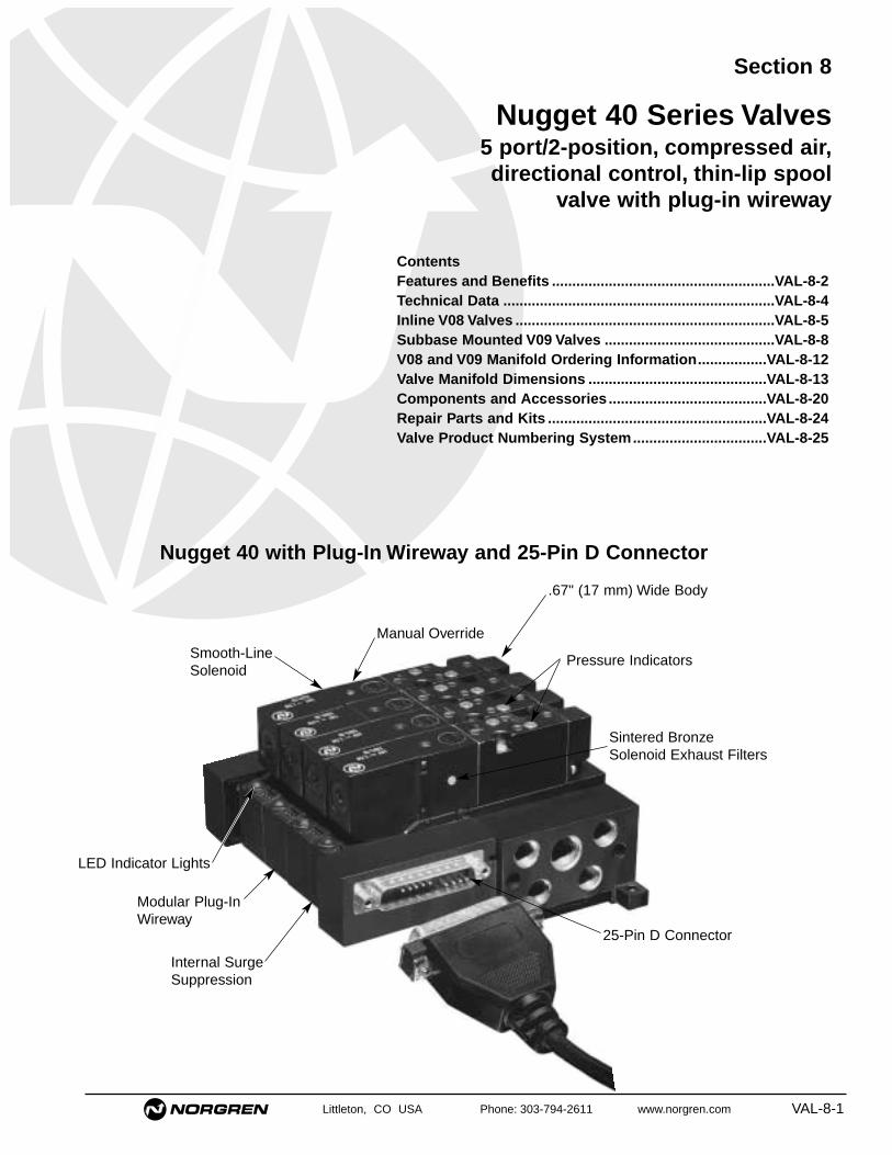
Littleton, CO USA Phone: 303-794-2611 www.norgren.com VAL-8-1
Section 8
.67" (17 mm) Wide Body
Nugget 40 with Plug-In Wireway and 25-Pin D Connector
Internal SurgeSuppression
25-Pin D Connector
Modular Plug-InWireway
LED Indicator Lights
Smooth-LineSolenoid
Manual Override
Pressure Indicators
Sintered BronzeSolenoid Exhaust Filters
Nugget 40 Series Valves5 port/2-position, compressed air,directional control, thin-lip spool
valve with plug-in wireway
ContentsFeatures and Benefits .......................................................VAL-8-2Technical Data ...................................................................VAL-8-4Inline V08 Valves ................................................................VAL-8-5Subbase Mounted V09 Valves ..........................................VAL-8-8V08 and V09 Manifold Ordering Information.................VAL-8-12Valve Manifold Dimensions ............................................VAL-8-13Components and Accessories .......................................VAL-8-20Repair Parts and Kits ......................................................VAL-8-24Valve Product Numbering System.................................VAL-8-25

Nugget 40 Series Valves
VAL-8-2 Littleton, CO USA Phone: 303-794-2611 www.norgren.com
Operator OptionsSolenoid pilot and air pilot operators areavailable for primary actuation and secondaryreturn operation. Air assisted spring returnoperators are also available for returnoperation.
Rotatable Connector and CoilThe standard cable grip connector can berotated in 90° increments, and the solenoidpilot coil can be turned in increments of 180°,making the operators adaptable for easyinstallation.
Electrical Connector OptionsOptions include a 10-foot, three-conductor,molded cable with or without LED and surgeprotection. See Product Numbering System onpage VAL-8-25 for specifics on optionalelectrical connector availability.
Valve AccessoriesSaddle Blocks are used with inline valves onmodular or fixed length manifolds. Theyincrease the flow of the inline valve up to Cv =0.35, and allow the user to replace the valvewithout disturbing the plumbing. 1/4", 5/32", or6 mm cartridge push-in fittings are used.
Pressure Indicators, standard on saddleblocks and subbase valves, show whichcylinder port is pressurized for increaseddiagnostic capability.
Blanking plates are available for coveringunused stations on inline and subbasemanifolds.
Dual sandwich speed control is mountedbetween the subbase valve and subbase and isused to meter exhaust flow for cylinder speedcontrol.
The Nugget 40 Valve is ideally suited for applications designedaround low cost PC’s coupled with small electro-pneumaticinterface modules. Its high flow (Cv Of 0.4) and compact profile.67" (17 mm) make it ideal for the limited space available in today’scontrol cabinets.
Two Year Unconditional Warranty All Nugget 40 valves are warranted to be free from defects for a fulltwo years from the date of purchase. This extended warrantyperiod provides users with a valuable guarantee of quality andservice.
Compact Dimensions Valves are a slim .67" (17 mm) wide and 4.02" (102 mm) long in asingle solenoid pilot configuration.
Pre-lubricated for Life On assembly, every Nugget 40 spool is pre-lubed for the life* of thevalve. This allows non-lubricated air service.
* (Approximately 20 million cycles with lubricated air service.Non-lubricated air will reduce the number of cycles.)
High-flow Design Improvements to body and base design combine to substantiallyincrease flow. Base galleries linked to the zinc die cast bodycombine with deep cavities to provide flow levels comparable tomuch larger 1/8" NPT size valves. Inline valves have a Cv of 0.26and subbase valves have a Cv of 0.41.
Thin Lip Seal SpoolNorgren Nugget 40 valves feature a lightweight, one-piecealuminum spool and nitrile seal assembly. The one piece spooland seal assembly is easily serviced, resulting in cost savingsduring maintenance. Durable low friction lip seals are designed tooperate with lubricated or non-lubricated air, and can be used formulti-pressure applications.
Port and Operator Identification Each of the ports is identified by a permanent number adjacent tothe port on the body or subbase. In addition, a two-digit number ateach end of the valve body indicates the ports connected when theoperator is actuated. Port and operator identification on all Nugget40 valves comply with ANSI/(NFPA) T3.21.15-1989.
DIN Rail Mounting Nugget 40 manifolds and subbases can be mounted to DIN rails;OEM’s building machines for export can take advantage of thisfeature.
Quality Appearance Norgren’s matt black color gives any control circuit installation aquality appearance, reflecting the superior operating capability builtinto every Nugget 40 Valve.
Sintered Bronze Solenoid Pilot Exhaust FiltersSolenoid pilot internal parts are protected by a built-in sinteredbronze solenoid pilot exhaust filter.
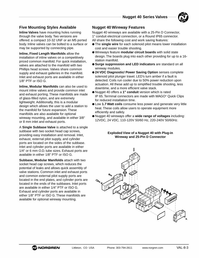
Nugget 40 Series Valves
Littleton, CO USA Phone: 303-794-2611 www.norgren.com VAL-8-3
Five Mounting Styles AvailableInline Valves have mounting holes runningthrough the valve body. Two versions areoffered: a compact 10-32 UNF or an M5 portedbody. Inline valves can be bolted to a surface ormay be supported by connecting pipe.
Inline, Fixed Length Manifolds allow theinstallation of inline valves on a competitivelypriced common manifold. For quick installation,valves are attached to the manifold with twoPhillips head screws. Valves share commonsupply and exhaust galleries in the manifold.Inlet and exhaust ports are available in either1/8" PTF or ISO G.
Inline, Modular Manifolds can also be used tomount inline valves and provide common inletand exhaust porting. These manifolds are madeof glass-filled nylon, and are extremelylightweight. Additionally, this is a modulardesign which allows the user to add a station tothe manifold for future expansion. Thesemanifolds are also available for optionalwireway mounting, and available in either 3/8"or 8 mm inlet and exhaust ports.
A Single Subbase Valve is attached to a singlesubbase with two socket head cap screws,providing easy installation and removal. Inlet,exhaust, external pilot supply, and cylinderports are located on the sides of the subbase.Inlet and cylinder ports are available in either1/4" or 6 mm O.D. tube sizes. Exhaust ports areavailable in either 1/8" PTF or ISO G.
Subbase, Modular Manifolds attach with twosocket head cap screws, which reduces thepotential of leaks and allows quick assembly ofvalve stations. Common inlet and exhaust portsand common external pilot supply ports arelocated in the end plates, and cylinder ports arelocated in the ends of the subbases. Inlet portsare available in either 1/4" PTF or ISO G.Exhaust and cylinder ports are available ineither 1/8" PTF or ISO G. These manifolds areavailable for optional wireway mounting.
Nugget 40 Wireway FeaturesNugget 40 wireways are available with a 25-Pin D Connector, 1" conduit electrical connection, or a Round IP65 connector.All share the following cost and work saving features:● The single wire for each solenoid pilot means lower installation
cost and easier trouble shooting.● Wireways feature modular circuit boards with solid state
design. The boards plug into each other providing for up to a 16-station manifold.
● Surge suppression and LED indicators are standard on allwireway modules.
● 24 VDC Diagnostic/ Power Saving Option senses completesolenoid pilot plunger travel. LED’s turn amber if a fault isdetected. Coils run cooler due to 50% power reduction uponactuation. All these add up to simplified trouble shooting, lessdowntime, and a more efficient valve stack.
● Nugget 40 offers a 1" conduit version which is rated IP 65. Terminal connectors are made with WAGO® Quick Clipsfor reduced installation time.
● Low 1.7 Watt coils consume less power and generate very littleheat. These coils allow users to operate equipment moreefficiently and safely.
● Nugget 40 wireways offer a wide range of voltages including:12VDC, 24 VDC, 110-120V 50/60 Hz, 220-240V 50/60Hz.
Exploded View of a Nugget 40 with Plug-inWireway and 25-Pin D Connector

Nugget 40 Series Valves
VAL-8-4 Littleton, CO USA Phone: 303-794-2611 www.norgren.com
Technical DataFluids: Filtered and lubricated or non-lubricated
compressed air
Operation: Thin lip spool valve, air pilot orsolenoid pilot actuated
Inlet Pressure Ranges
Solenoid Pilot Operated Valves* –With Internal Pilot Supply:
44 to 150 psig (3 to 10.3 bar)With External Pilot Supply:
26" Hg to 150 psig (26" Hg to 10.3 bar)**Air Pilot Operated Valves:
26" Hg to 150 psig (26" Hg to 10.3 bar)**
* Solenoid pilot operators must be externally piloted if the supply pressureto the main valve is below the minimum pilot pressure listed in the tablebelow.
** With vacuum source plumbed to an exhaust port, and 135 psig (9.3 bar) maximum at inlet port.
Operating Pilot PressuresMaximum Pressure: 150 psig (10.3 bar)
Minimum Pilot Pressures
Pressure Indicators –Minimum indicator pressure: 44 psig (3 bar)
Operating Temperatures –Air Pilot Operated Valves: -4°F to 176°F (-20°C to 80°C)✝Solenoid Pilot Operated Valves: 20°F to 122°F(-6°C to 50°C)
✝ With a dew point of supply air less than air temperature below 35°F (2°C)
Port SizeIn-line: 10-32 UNF, M5Inline, Fixed Length Manifold: 1/8" PTF or ISO G.Inline, Modular Manifold: 3/8" or 8 mm O.D. tube
inlet and exhaust ports.Saddle Block: 1/4", 5/32", 4 and 6 mm O.D tube.Single Subbase Version A - 1/8" PTF or ISO G exhaust ports, 1/4" or
6 mm O.D. tube inlet and cylinder ports.Single Subbase Version B - 1/8" NPT inlet, exhaust, and cylinder ports.Subbase, Modular Manifold: 1/4" PTF or ISO G
inlet port,1/8" PTF or ISO G cylinder andexhaust ports.
MountingIn-line valve: through-holes in valve bodySubbase valve: through holes to subbase and manifoldManifold Mounted: through holes in end plate or to a 35 mm DIN rail
Average Flow Factor (Cv)*In-line Mounted
10-32 UNF or M5 ports: Cv .265/32" or 4 mm saddle block: Cv .231/4" or 6 mm saddle block: Cv .35
Subbase mounted: Cv 0.41
*FIow rating determined in accordance withANSI/NFPA/T3.21.3, Pneumatic Fluid Power FlowTest Procedure and Reporting Method, for fixedorifice components.
Solenoid Pilot Operator SpecificationsDuty: Continuous at 90 to 110% of rated voltage.
Coil Type: Molded with three-pin electrical plug-inconnector. 8 mm pin spacing conforms to DIN 43650, Form C.
Electrical Plug-in Connector: Cable grip for cables upto 7/32" (5.6 mm) in diameter or with 10-ft moldedcable.
Enclosure Classification: NEMA 4, DIN 40050-lP65
Wireway Enclosure Classification –25-Pin D Connector: NEMA 11" Conduit Connector: IP65, NEMA 4Round Connector: IP65
Override: Non-locking or combination.
Materials of ConstructionValve Materials –
Body, air pilot, return operator: ZincSpool: AluminumElastomers: Nitrile
Solenoid pilot operator–Base: PPS PlasticPlunger and Spring: Stainless SteelCoil Housing: Epoxy thermoset
Subbase Materials –lnline, Modular Manifold: Glass filled nylonInline, Fixed Length Manifold: AluminumSubbase, Modular Manifold: Aluminum and zincElastomers: Nitrile
Wireway Materials –Modules and end plates: Glass filled nylonConduit end plate: Zinc
Response Times* @ 132 psig (9 bar)Type mSec
On Off
Inline Sol pilot/Air pilot Assisted Sprg 20 22Sol pilot/Sol pilot 20 20
Subbase Sol pilot/Air pilot Assisted Sprg 18 16Sol pilot/Sol pilot 18 18
*Response times are based on 50% rise/fall of inlet pressure at outlet port.
14 End 12 End Minimum OperatorPrimary Secondary PressureOperator Return Operator psig (bar)Air Pilot Air pilot 29 (2.0)
Large Air pilot Small Air pilot 22 (1.5) at 1 4 end
44 (3.0) at 1 2 end
Air pilot Air pilot-Assisted spring 44 (3.0)
Solenoid pilot Solenoid pilot 29 (2.0)
Solenoid pilot** Air pilot-assisted spring 44 (3.0)
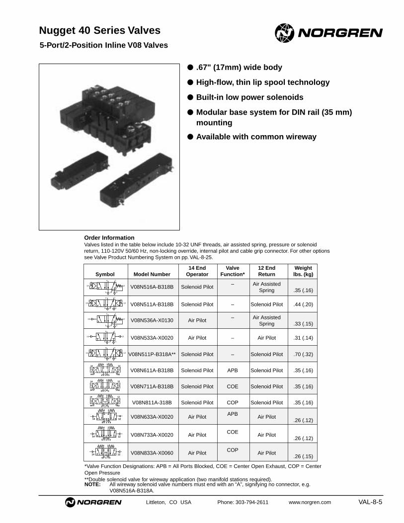
Littleton, CO USA Phone: 303-794-2611 www.norgren.com VAL-8-5
4 2
14 125 1 3
4
5 1 3
2
14 12
4
5 1 3
2
14 12
4 2
84
12
82
14
5 1 3
4
5 1 3
214
84
12
82
4
5 1 3
2
84 82
14 12
4 2
1214
315
4 2
1214
315
4 2
1214
315
4 2
1214
315
4 2
1214
315
● .67" (17mm) wide body
● High-flow, thin lip spool technology
● Built-in low power solenoids
● Modular base system for DIN rail (35 mm)mounting
● Available with common wireway
Nugget 40 Series Valves5-Port/2-Position Inline V08 Valves
14 End Valve 12 End WeightSymbol Model Number Operator Function* Return lbs. (kg)
V08N516A-B318B Solenoid Pilot – Air AssistedSpring .35 (.16)
V08N511A-B318B Solenoid Pilot – Solenoid Pilot .44 (.20)
V08N536A-X0130 Air Pilot – Air AssistedSpring .33 (.15)
V08N533A-X0020 Air Pilot – Air Pilot .31 (.14)
V08N511P-B318A** Solenoid Pilot – Solenoid Pilot .70 (.32)
V08N611A-B318B Solenoid Pilot APB Solenoid Pilot .35 (.16)
V08N711A-B318B Solenoid Pilot COE Solenoid Pilot .35 (.16)
V08N811A-318B Solenoid Pilot COP Solenoid Pilot .35 (.16)
V08N633A-X0020 Air Pilot APB Air Pilot.26 (.12)
V08N733A-X0020 Air Pilot COE Air Pilot.26 (.12)
V08N833A-X0060 Air Pilot COP Air Pilot.26 (.15)
Order InformationValves listed in the table below include 10-32 UNF threads, air assisted spring, pressure or solenoidreturn, 110-120V 50/60 Hz, non-locking override, internal pilot and cable grip connector. For other optionssee Valve Product Numbering System on pp. VAL-8-25.
*Valve Function Designations: APB = All Ports Blocked, COE = Center Open Exhaust, COP = CenterOpen Pressure**Double solenoid valve for wireway application (two manifold stations required).NOTE: All wireway solenoid valve numbers must end with an “A”, signifying no connector, e.g.
V08N516A-B318A.

Nugget 40 Series ValvesAll Dimensions in Inches (mm)
VAL-8-6 Littleton, CO USA Phone: 303-794-2611 www.norgren.com
V08N516A-B318BSingle Solenoid Pilot, Air Assisted Spring Return
14 125 1 3
4
2
.67
(17) .0
6 (1
1)
.49
(13)
2.59 (66).47(12)
2.50 (64)
.24 (6)
10-32 UNF
.11 (3)
.65 (17)
Manual Overide
2.17
(55
)
1.14
(29
)
.24
(6)
.98
(25)
4.55 (116)
4.02 (102)
2.83 (72)
10-32 UNF
2.59 (66) .47(12)
.10 (3)
.94 (24)
.31
(8)
V08N511A-B318BDouble Solenoid Pilot
14 125 1 3
.67
(17)
.06
(11)
.49
(13)
2.59 (66).47(12)
2.50 (64)
.24 (6)
.11 (3)
.65 (17)
Manual Overide Manual Overide
2.17
(55
)
1.14
(29
)
.24
(6)
.98
(25)
6.74 (171)
5.63 (143)
2.83 (72)
10-32 UNF
2.59 (66) .47(12)
.10 (3)
.94 (24)
10-32 UNF
.31
(8)
4
2
V08N536A-X0130Air Pilot Operated, Air AssistedSpring Return
14 125 1 3
2
4
.67
(17)
.49
(13)
.98 (25) .47(12)
.86 (22).65(17)
.24 (6)
.11 (3)
.06
(11)10-32 UNF
.98
(25) .4
9(1
3)
.24
(6)
.98 (25) .47(12)
2.40 (61)
1.18 (30)
.31
(8)
.10 (3)
10-32 UNF
10-32 UNF
.94 (24)
.33(9)
V08N533A-X0020Double Air Pilot Operated
14 125 1 3
2
4
.67
(17)
.49
(13)
.98 (25) .47(12)
.88 (23).65(17)
.24 (6)
.11 (3)
.06
(11)10-32 UNF
.98
(25) .4
9(1
3)
.24
(6)
.98 (25) .47(12)
2.43 (62)
1.18 (30)
.31
(8)
.10 (3)
10-32 UNF
10-32 UNF
.94 (24)
.33(9)

Nugget 40 Series ValvesAll Dimensions in Inches (mm)
Littleton, CO USA Phone: 303-794-2611 www.norgren.com VAL-8-7
V08N511P-B318ADouble Solenoid Pilot Valve for Wireway ApplicationNOTE: Two manifold stations required.
V08N*33A-X0020 Model5/3 Double Pilot Valve
V08N611A-B318BDouble Solenoid Pilot Valve for Wireway Application
.67
(17)
.33
(9)
.06
(1)
1.38
(35
)
2.59 (66)
10-32 UNF
.47(12)
2.50 (64)
Manual Override
.65 (17)
.49
(13)
.24 (6)
.11 (3)
1.14
(29
)
.98
(25)
.24
(6)
4.02 (102)
2.83 (72)
10-32 UNF
.94 (24)
‘14’ ‘12’‘5’ ‘1’ ‘3’
Inline, Fixed Length Manifold
51
3
51
3
1.94
(49
)
.65
(17)
1.30
(33
)
A
.20(5)
.20(5)
.68(17)
.35 (9)
1/8" PTFor ISO G
.85 (22).71 (18)
.16
(4)
Model Number Number1/8" PTF 1/8" ISO G of Stations A
V10026-N02 V10026-G02 2 2.28 (58)V10026-N04 V10026-G04 4 3.70 (94)V10026-N06 V10026-G06 6 5.12 (130)V10026-N08 V10026-G08 8 6.54 (166)V10026-N10 V10026-G10 10 7.95 (202)V10026-N12 V10026-G12 12 9.37 (238)
NOTE: Gaskets and valve mounting screws are supplied with these manifoldsOrdering Example for Valves Assembled to a Fixed Length Manifold —Provide the following information:1. Manifold part number2. Valve part number3. Assembly chargeExample –1 fixed length manifold, part number V10026-N02, consisting of two valves, partnumbers V08N516A-B318B, and two assembly charges, part numbers99 055 530 (2).
2.6 (65) .48 (12)
10-32 UNF
.49
(13)
.34
(9).6
7 (1
7)
.24 (6)
2.50 (63) .65 (17)
.04(
1)
10-32 UNF
6.7 (171)
.95 (24)
2.8 (71)
6.2 (157)
.24
(6)
1.0
(25)
.32
(8)
1.15
(29
)1.
86 (
47)
.44
(11)
Manual Override
'5' '1' '3' '12''14'
.49
(13)
.67
(17)
10-32 UNF
.47 (12).95 (24)
.24 (6)
1.44 (37).65 (17)
4
2
10-32 UNF
.95 (24)
1.18 (30)
3.0 (75)
'14'
'5' '1' '3'
'12'
.32
(8)
.24
(6)
1.0
(25)
10-32 UNF
.50
(13)
.34 (9)
Multi-Pressure PlugV10511-R01

Nugget 40 Series Valves
VAL-8-8 Littleton, CO USA Phone: 303-794-2611 www.norgren.com
4 2
14 125 1 3
4
5 1 3
2
14 12
4
5 1 3
2
14 12
4 2
84
12
82
14
5 1 3
4
5 1 3
214
84
12
82
4
5 1 3
2
84 82
14 12
4 2
1214
315
4 2
1214
315
4 2
1214
315
4 2
1214
315
14
4 2
12
315
4 2
1214
315
14 End Valve 12 End WeightSymbol Model Number Operator Function* Return lbs. (kg)
V096516A-B318B Solenoid Pilot – Air AssistedSpring .35 (.16)
V096511A-B318B Solenoid Pilot – Solenoid Pilot .44 (.20)
V096536A-X0130 Air Pilot – Air AssistedSpring .33 (.15)
V096533A-X0020 Air Pilot – Air Pilot .31 (.14)
V096533A-X0060 Large Air Pilot – Small Air Pilot .31 (.14)
V096511P-B318A** Solenoid Pilot Solenoid Pilot .70 (.32)
V096611A-B318B Solenoid Pilot APB Solenoid Pilot .44 (.21)
V096711A-B318B Solenoid Pilot COE Solenoid Pilot .44 (.21)
V096811A-B318B Solenoid Pilot COP Solenoid Pilot .44 (.21)
V0966DDA-X0020 Air Pilot APB Pilot .33 (.15)
V0967DDA-X0020 Air Pilot COE Pilot .33 (.15)
V0968DDA-X0020 Air Pilot COP Pilot .33 (.15)
Nugget 40 Series Valves
● .67" (17 mm) wide body
● High-flow thin lip spool
● Built-in low power solenoids
● Optional DIN rail mounting
● Suitable for non-lubricated air supplies
● Available with common wireway
5-Port/2-PositionSubbase Mounted V09 Valves
Order InformationValves listed in the table are less subbase, with air assisted spring, pressure or solenoid return, 110-120V 50/60 Hz, non-locking override, internalpilot and cable grip connector. For other options see Valve Product Number System on pp. VAL-8-12/25.
*Valve Function Designations: APB = All Ports Blocked, COE = Center Open Exhaust, COP = Center Open Pressure**Double solenoid valve for wireway application (two manifold stations required).NOTE: All wireway solenoid valve numbers must end with a “A”, signifying no connector, e.g. V08N516A-B318A.

Nugget 40 Series ValvesAll Dimensions in Inches (mm)
Littleton, CO USA Phone: 303-794-2611 www.norgren.com VAL-8-9
V096516A-B318BSingle Solenoid Pilot, Air Assisted Spring Return
‘14’ ‘12’
.67
(17)
.49
(13)
2.17
(55
)
1.14
(29
)
.98
(25)
.04
(1)
4.55 (116)
4.02 (102)
2.50 (64) .65 (17)
Position Indicators
Manual Override
V096511A-B318BDouble Solenoid Pilot
‘14’ ‘12’
.67
(17)
.49
(13)
2.17
(55
)
1.14
(29
)
.98
(25)
.04
(1)
6.74 (171)
5.63 (143)
2.50 (64) .65 (17)
Position Indicators
Manual Override Manual Override
V096*11A-B318B Models5/3 Double Solenoid Valve
1.14
(29
)
'14' '12'1.9
(47)
.43
(11)
6.74 (171)
.1 (
25)
.25
(6)
6.19 (157)
Manual Override
.20 (5)
.50
(13)
.34
(9).6
7 (1
7)
V096*DDA–X0020 Model5/3 Double Pilot Valve
.50
(13)
.67
(17)
.24 (6)
1.44 (37).65 (17)
4
2
10-32 UNF x.02 (05)
3.0 (75)
'14' '12'
.32
(8)
.24
(6)
1.0
(25)
.04
(1)
.24
(6)

Nugget 40 Series ValvesAll Dimensions in Inches (mm)
VAL-8-10 Littleton, CO USA Phone: 303-794-2611 www.norgren.com
V096536A-X0130Air Pilot Operated,Air Assisted Spring Return
‘14’ ‘12’‘2’
‘4’
.67
(17)
.49
(13)
2.40 (61)
.98
(25)
.04
(1)
.89 (23)
Position Indicator
.65 (17)
V096533A-X0060Large Air Pilot Operated,Small Air Pilot Return
‘14’ ‘12’‘2’
‘4’
.67
(17)
.49
(13)
2.43 (62)
.98
(25)
.04
(1)
.89 (23)
Position Indicator
.65 (17)
V096*11P-B318ADouble Solenoid Pilot Valve for Wireway ApplicationsNOTE: Two manifold stations required.
.67
(17)
1.14
(29
)
.98
(25)
.49
(13)
.04
(1)
2.50 (64) .65 (17)
4.02 (102)
Position Indicator
Manual Override
‘4’
‘2’
1.38
(35
)
‘12’‘14’
V096533A-X0020Double Air Pilot Operated
‘14’ ‘12’‘2’
‘4’
.67
(17)
.49
(13)
2.43 (62)
.98
(25)
.04
(1)
.89 (23)
Position Indicator
.65 (17)

Nugget 40 Series ValvesAll Dimensions in Inches (mm)
Littleton, CO USA Phone: 303-794-2611 www.norgren.com VAL-8-11
.31
(8)
.24
(6)
.45
(11)
.41
(10)
2.36 (60) .09 (2)
1.89 (48) .24 (6)
1.23 (31)
1.22
(31
)
.50
(13)
.28
(7)
.94 (24)
Ø .17 (4)
M5 x .08x .39 (10) Deep
.93
(24)
1.18 (30)1/4" O.D. Tube
Inlet Port
1/4" O.D. TubeCylinder Ports10-32 UNF
External Pilot Ports
Threaded ExhaustPort
.87 (22)
1.26 (32)
‘12’
‘5’
‘1’ ‘12’
‘4’
‘2’
1.26
(32
)
Single Subbase (Version A)
Type: Single station subbase with inlet, exhaust,cylinder and external pilot ports.
Model Number: V10038-N00Porting: 1/4" O.D. Tube push-in connector.
Model Number: V10038-G00Porting: 6 mm O.D. tube push-in connector
Single Subbase (Version B)
Type: Single station subbase with inlet,exhaust, cylinder and external pilot ports.
Model Number: 81-119-61Porting: 1/8" NPT
145
121
3
42
.75
(19)
.87
(22)
.55
(14)
1.89
(48
).2
4 (6
)
1.26
(32
)2.
36 (
60)
1.25 (32)
.24(6)
.88
(22) 1.48
(38
)
.53 (14).29 (7).34 (9)
.72 (18)1.21 (31)
1.18
(30
)
10-32 UNFExternal Pilot Ports

Nugget 40 Series Valves
VAL-8-12 Littleton, CO USA Phone: 303-794-2611 www.norgren.com
Ordering a Factory Assembled Nugget 40 Valve Modular Manifold
1. Select the valve and voltage from p. VAL-8-8, and indicate the station number on the base where each valve is to bepositioned.NOTE: Position 1 is referenced from the right hand end. See photo below.
2. Select the base configuration using the following as a guide.
Product Family
Product Line andMounting Variation
Porting
Wireway Connector
V = Valve Product
2 = 3/8 O.D. Tube - Inlet, Exhaust8 = 8 mm O.D. - Inlet, Exhaust
R = 1/4 PTF Supply, 1/8 PTF Cylinder/ExhaustB = 1/4 ISO G Supply, 1/8 ISO G Cylinder/ExhaustH = 1/4 ISO Rc Supply, 1/8 ISO Rc Cylinder/ExhaustL = 1/4 PIF cylinder, 1/4 PTF supply,
1/8 PTF exhaust
1
2 3
4
Wireway Options5
6
A = Standard wireway or No wirewayB = 24 VDC Diagnostic Wireway (common negative)
13 Wireway Voltage12
11
V 0 9 R B C 0 7 – X X X 1 3
08 = Nugget 40, Inline Modular Manifold 09 = Nugget 40, Subbase Modular Manifold
X = Default
XX = No Wireway13 = 12 - 24 VDC18 = 110-120V 50/60 Hz19 = 220-240V 50/60 Hz
Position
NOTE: The Maximum number of stations in anassembly is 16: the total of positions 7-8,and 9-10.
Ordering ExampleThe following ordering example details the information needed to order the 4-valve assembly shown at right.
One Nugget 40, 4-valves stack consisting of:Position Quantity Part No. Description
1 V09RAA02-02X13 Manifold Assembly1-4 4 V096516A-B313A Single Solenoid Valve
NOTE: Product number includes isolating plugs.For additional accessories such as Blanking Plates see p. VAL-8-20.
Left end
Right end
X = No WirewayA = 25-pin D connector (common negative)B = Round IP-65 (common negative)C = 1" PTF conduit (common negative)D = 25-pin D connector (common positive)E = Round IP-65 (common positive)F = 1" PTF conduit (common positive)
7 8
9 10 Number of Stations
Number of stations for single pressure manifold
02 to 20 stations = 25-pin D connector02 to 18 stations = Round IP-6502 to 16 stations = 1" PTF conduit
XX = Single Pressure Application01 to 15 = Number of stations for dual
pressure into manifold

Nugget 40 Series Valves
Littleton, CO USA Phone: 303-794-2611 www.norgren.com VAL-8-13
Inline, Modular Manifold for V08 Valves
‘14’ ‘12’
‘1’ ‘35’
N x
.71
(18)
+ .7
1 (1
8)
.71
(18)
.35
(9)
.35
(9)
.71
(18)
1.77 (45)
2.44 (62)
.18 (5) Dia
.91 (23)
N = Number of Stations
Right Hand End
3/8" or 8 mmO.D. Tube
.63 (16)
1.26
(32
)
2.17
(55
)
3.43
(87
)
3.07
(78
)
6.14 (156)
.29
(7)
.04
(1)
‘1’
‘4’
‘3/5’
‘1’ ‘3/5’
‘2’‘4’
‘2’‘4’
‘2’
‘4’
‘2’
Left Hand End
Position 1
All Dimensions in Inches (mm)

Nugget 40 Series ValvesAll Dimensions in Inches (mm)
VAL-8-14 Littleton, CO USA Phone: 303-794-2611 www.norgren.com
Inline, Modular Manifold with Common Wirewayand 25-Pin D Connector for V08 Valves
‘1’
‘4’
‘1’ 3/5
‘2’
3/5
‘12’‘14’
‘1’ ‘35’
N x
.71
(18)
+ .7
1 (1
8)
.71
(18)
.35
(9)
.35
(9)
.71
(18)
1.77 (45)
4.81 (122)
N= Number of Stations
.18 (5) Dia
.91 (23)
3/8" or 8 mmO.D. Tube
.63 (16)
Left Hand End
Right Hand End
Position 1
LED
.75
(19)
1.10
(28
)
3.07
(78
)
2.17
(55
).0
4 (1
)
1.26
(32
)
.29
(7)

Nugget 40 Series ValvesAll Dimensions in Inches (mm)
Littleton, CO USA Phone: 303-794-2611 www.norgren.com VAL-8-15
Inline, Modular Manifold with Common Wirewayand 1" Conduit Connection for V08 Valves
‘1’
‘4’
‘1’ 3/5
‘2’
3/5
‘12’‘14’
‘1’ ‘35’
N x
.71
(18)
+ .7
1 (1
8)
.71
(18)
.35
(9)
.35
(9)
.71
(18)
1.72
(44
)
2.48 (63)
1.24 (32)
1" NPT
4.81 (122)
N= Number of Stations
.18 (5) Dia
.91 (23)
3/8" or 8 mmO.D. Tube
.63 (16)
Left Hand End
Right Hand End
Position 1
LED
1.12
(29
)2.24
(57
)
3.07
(78
)
2.17
(55
).0
4 (1
)
1.26
(32
)
.29
(7)
1" conduit housingw/conduit entry plateremoved showing quickconnects.
1 2 3 4 5 6 7 8 9 10
C E 111213141516

Nugget 40 Series ValvesAll Dimensions in Inches (mm)
VAL-8-16 Littleton, CO USA Phone: 303-794-2611 www.norgren.com
Subbase, Modular Manifold for V09 ValvesN
x .7
1 (1
8) +
1.7
4 (4
4).5
1(1
3)
.87
(22)
.25
(6)
.71
(18)
.35
(9)
2.34 (59)
Right Hand End
‘14’
‘1’
‘3’‘5’
‘12’/‘14’
‘12’
Left Hand End
.17 (4) Dia.
.31
(8)
.72 (18)
1/8" CylinderPort
.51(13)
1.53
(39
).0
4 (1
)
1.13
(29
)
1/4" Inlet Port
1/8" Exhaust Ports
1.21
(31
)
.54
(14)
.41
(10)
2.34 (59)
1.45 (37)
1.11 (28)
.69 (18)
.44(11)
N = Number of Stations
‘4’‘2’
‘4’‘2’

Nugget 40 Series ValvesAll Dimensions in Inches (mm)
Littleton, CO USA Phone: 303-794-2611 www.norgren.com VAL-8-17
Subbase, Modular Manifold with Common Wireway and25-Pin Connector for V09 Valves
‘4’
‘2’
N x
.71
(18)
+ 1
.74
(44)
.51
(13)
.51
(13)
.87
(22)
.25
(6)
.71
(18)
.35
(5)
1.73 (44).25 (6)
4.82 (122)
Left Hand End
Right Hand End
.17 (4) Dia.
.31
(8)
.72 (18).51(13)
2.52
(64
)
2.24
(57
)
.75
(19)
1.53
(39
)
1.21
(31
)
1.13
(29
)
.54
(14)
.04
(1)
.41
(10)
1/4" Inlet Port1/8" External Pilot
Supply Ports
1/8" Exhaust Ports
2.34 (59)
1.45 (37)
.22 (5.5)
1.11 (28)
.69 (18)
.44(11)
Position 1
LED
.51(13)
.51(13)1.23 (31)
N = Number of Stations
1/8" CylinderPort
‘4’‘2’
‘4’‘2’
.71
(18)
‘12’‘14’
‘12’/‘14’

Nugget 40 Series ValvesAll Dimensions in Inches (mm)
VAL-8-18 Littleton, CO USA Phone: 303-794-2611 www.norgren.com
Subbase, Modular Manifold with Common Wireway and1" Conduit Connector for V09 Valves
‘4’
‘2’
N x
.71
(18)
+ 1
.74
(44)
.51
(13)
.51
(13)
.87
(22)
1.72
(44
)
.25
(6)
.71
(18)
.35
(5)
1.73 (44).25 (6)
4.82 (122)
Left Hand End
Right Hand End
.17 (4) Dia.
.31
(8)
.72 (18).51(13)
2.52
(64
)
2.24
(57
)
1.12
(29
)
1.53
(39
)
1.21
(31
)
1.13
(29
)
.54
(14)
.04
(1)
.41
(10)
1/4" Inlet Port
1/8" External PilotSupply Ports
1/8" Exhaust Ports
2.34 (59)
1.45 (37)
.22 (5.5)
1.24 (32)
1" NPT
1.11 (28)
.69 (18)
.44(11)
Position 1
LED
.51(13)
.51(13)1.23 (31)
N = Number of Stations
1/8" CylinderPort
‘4’‘2’
‘4’‘2’
‘14’ ‘12’
1” conduit housingw/conduit entry plateremoved showing quickconnects.
1 2 3 4 5 6 7 8 9 10
C E 111213141516
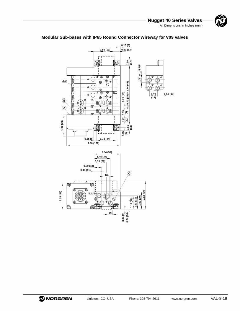
Nugget 40 Series ValvesAll Dimensions in Inches (mm)
Littleton, CO USA Phone: 303-794-2611 www.norgren.com VAL-8-19
Modular Sub-bases with IP65 Round Connector Wireway for V09 valves
4.80 (122)
1.73 (44)0.25 (6)
0.71
(18
)
N x
0.7
2 (1
8) +
1.7
4 (4
4)
LED
1.92
(49
)
‘2’
‘4’
‘2’
‘4’
0.35 (9)
1/4
1/8
0.72(18)
1/8"
or
1/4
PIF
‘4’‘2’
‘4’‘2’
0.50 (13)
0.04
(1)
‘1’
‘5’ ‘3’
‘12’/‘14’
2.28
(58
)
0.51
(13)
0.50
(13)
0.87
(22)
0.25 (6)
0.50 (13) 0.50 (13)
0.10 (3)
2.34 (59)
1.45 (37)
1.11 (28)
0.69 (18)
0.44 (11)
1.53
(39
)
2.52
(64
)
1.13
(29
)
0.54
(14
)
1.21
(31
)
A
B
C

Nugget 40 Series ValvesAll Dimensions in Inches (mm)
VAL-8-20 Littleton, CO USA Phone: 303-794-2611 www.norgren.com
Modular Manifold BlockType: Single station manifold blockModel Number: V085516A-Q01A8
End Plate KitsType: Consists of 1 left and 1 right end cap with inlet and
exhaust push-in connectors, and DIN rail clamp kit.Model Number V085516A-Q02A2Porting: 3/8" O.D. tube
Model Number: V085516A-Q02A8Porting: 8 mm O.D. tube
Saddle BlocksType: Push-in connector port block with integral
pressure indicators.
Model Number: V085516A-Q0404Porting: 5/32" (4 mm) O.D. tube
Model Number: V085516A-Q0416Porting: 1/4" O.D. tube
Model Number: V085516A-Q0406Porting: 6 mm O.D. tube
.35
(9)
.55(14)
M2.
5
.20 (5)
.20 (5)
.04 (1)
1.50
(38
) 38
1.08
(28
).43
(11)
.67 (17)
.49(13)
Blanking Plate KitType: Installed in place of a valve to allow an additional valve to
be added at a later date.Model Number V095516A-Q110
Tie rod kits w/ fastenersV085516A-Q03**** Insert number of stations 02-16 stations
NOTE: Kit includes (1) fixed length tie rod and fasteners.Subbases require (2) kits per manifold, and wireways require(1) kit per manifold. Length for subbase is determined by thenumber of stations to be manifolded. Length for wireway is onestation less e.g. V085516AQ0303 would be for a 4 stationwireway.
Wireway ModuleV085516A-Q0913 12-24 VDC with indicator, common
negativeV085516A-Q0918 110-120V 50/60 Hz w/indicatorV085516A-Q0919 220-240V 50/60 Hz w/indicatorV085516A-Q09B3 24 VDC Diagnostic / Power Saving,
common negativeV085516A-Q0953 12-24 VDC w/indicator, common
positive
V10249-K00Wireway Spacer
Wireway End Plate and Harness Kit with 25-Pin DsubconnectorV085516A-Q0604 4 stationsV085516A-Q0608 8 stationsV085516A-Q0612 12 stationsV085516A-Q0616 16 stations
V08 Wireway End Plate and Harness Kit with 1" conduitconnector V085516A-Q0804 4 stationsV085516A-Q0808 8 stationsV085516A-Q0812 12 stationsV085516A-Q0816 16 stations
Isolating Plugs for V08 Modular Manifold Valves Type: Permits the use of two different inlet pressures on
the same subbase assembly.Model Number V085516A-Q05AA
Components for V08 Inline Modular Manifolds
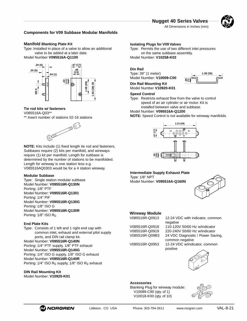
Nugget 40 Series Valves
Littleton, CO USA Phone: 303-794-2611 www.norgren.com VAL-8-21
All Dimensions in Inches (mm)
Manifold Blanking Plate KitType: Installed in place of a valve to allow an additional
valve to be added at a later date.Model Number V095516A-Q1100
Modular SubbaseType: Single station modular subbaseModel Number: V095516R-Q130NPorting: 1/8" PTFModel Number: V095516R-Q1301Porting: 1/4" PIFModel Number: V095516R-Q130GPorting: 1/8" ISO GModel Number: V095516R-Q130RPorting: 1/8" ISO Rc
End Plate KitsType: Consists of 1 left and 1 right end cap with
common inlet, exhaust and external pilot supply ports, and DIN rail clamp kit.
Model Number: V095516R-Q140NPorting: 1/4" PTF supply, 1/8" PTF exhaustModel Number: V095516R-Q140GPorting: 1/4" ISO G supply, 1/8" ISO G exhaustModel Number: V095516R-Q140RPorting: 1/4" ISO Rc supply, 1/8" ISO Rc exhaust
DIN Rail Mounting KitModel Number: V10920-K01
Isolating Plugs for V09 ValvesType: Permits the use of two different inlet pressures
on the same subbase assembly.Model Number: V10258-K02
Din RailType: 39" (1 meter)Model Number: V10009-C00
Din Rail Mounting KitModel Number V10920-K01
Speed ControlType: Restricts exhaust flow from the valve to control
speed of an air cylinder or air motor. Kit is installed between valve and subbase.
Model Number: V095516A-Q1200NOTE: Speed Control is not available for wireway manifolds.
Intermediate Supply Exhaust PlateType: 1/8" NPTModel Number: V095516A-Q160N
.29
(7)
1.38 (35)
M2.
5
.20 (5)
.20 (5)
.04 (1)
1.50
(38
) 38
1.08
(28
).43
(11)
.67 (17)
.49(13)
.67
(17)
.39
(10)
2.23 (59)
Tie rod kits w/ fastenersV085516A-Q03**** Insert number of stations 02-16 stations
NOTE: Kits include (1) fixed length tie rod and fasteners.Subbases require (2) kits per manifold, and wirewaysrequire (1) kit per manifold. Length for subbase isdetermined by the number of stations to be manifolded.Length for wireway is one station less e.g.V085516AQ0303 would be for a 4 station wireway.
Wireway ModuleV085516R-Q0913 12-24 VDC with indicator, common
negativeV085516R-Q0918 110-120V 50/60 Hz w/indicatorV085516R-Q0919 220-240V 50/60 Hz w/indicatorV085516R-Q09B3 24 VDC Diagnostic / Power Saving,
common negativeV085516R-Q0953 12-24 VDC w/indicator, common
positive
AccessoriesBlanking Plug for wireway module:
V10089-C90 (qty. of 1)V10018-K00 (qty. of 10)
Components for V09 Subbase Modular Manifolds

Nugget 40 Series ValvesAll Dimensions in Inches (mm)
VAL-8-22 Littleton, CO USA Phone: 303-794-2611 www.norgren.com
V10249-K00Wireway Spacer
Wireway End Plate and Harness Kit with 25-Pin DsubconnectorV095516A-Q0604 4 stationsV095516A-Q0608 8 stationsV095516A-Q0612 12 stationsV095516A-Q0616 16 stationsV095516A-Q0620 20 stations
Wireway End Plate and Harness Kit with 1" conduitconnector V095516A-Q0804 4 stationsV09556A-Q0808 8 stationsV095516A-Q0812 12 stationsV095516A-Q0816 16 stations
LED's
2.5 (63)
.40
(10)
2.17
(55
)35
x
Nugget 40 end plate 4 outputs VE1MP09B-00400
Remote Output Modules
Application:Remote output modules are used with Nugget 40 and Nugget 120valve manifolds to provide up to 4 outputs to remote devices such asExcelon, and Prospector poppet valves. Harness assemblies shouldbe increased by the relevant number of stations.
Components for V09 Subbase ModularManifolds (cont.)

Nugget 40 Series ValvesAll Dimensions in Inches (mm)
Littleton, CO USA Phone: 303-794-2611 www.norgren.com VAL-8-23
0.79 (20)0.6 (1.5) 1.69 (43)
0.94
(24
)
0.94 (24) AF
3.23 (82) 0.98 (25)
‘A’
1.30
(33
)
0.28 (7)0.31 (8)
1.10
(28
)
Model A Weight (Kg)V10021–E01 3 (1m) .75 (.34)V10021–E03 10 (3m) 1.63 (.74)V10021–E05 16 (5m) 2.51 (1.14)V10021–E08 26 (8m) 4.67 (2.12)V10021–E10 32 (10m) 5.89 (2.67)
Pin. Socket Plug Pin. Socket PlugA Solenoid 1 Red N Solenoid 13 BlackB Solenoid 2 Blue P Solenoid 14 Green/redC Solenoid 3 Green R Solenoid 15 Yellow/redD Solenoid 4 Yellow S Solenoid 16 White/redE Solenoid 5 White T Solenoid 17 Red/blackF Solenoid 6 Brown U Solenoid 18 Red/brownG Solenoid 7 Violet V Common,-negative Yellow/blueH Solenoid 8 Orange W Common,-negative White/blueJ Solenoid 9 Pink X Common,-negative Blue/blackK Solenoid 10 Turquoise Y Common,-negative Orange/blueL Solenoid 11 Grey Z Common, -ground Yellow/greenM Solenoid 12 Red/blue
IP65 ‘Round’ Connector
Type: 23 pin IP65 ‘Round’ connector. Cable size 20 AWG (.52 mm2)
Round Connector with Cable
Solenoid No. 1 is nearest to the connector on valve manifold
A
.98(25)
13
12
11
10
9
8
7
6
5
4
3
2
1
25
24
23
22
21
20
19
18
17
16
15
14
SocketModel Number AV10020-E01 3' (1.0m)V10020-E03 10' (3.0m)V10020-E05 16' (5.0m)
Pin No. Socket Plug Pin No. Socket Plug1 Solenoid 1 Red 14 Solenoid 14 Green/red2 Solenoid 2 Blue 15 Solenoid 15 Yellow/red3 Solenoid 3 Green 16 Solenoid 16 White/red4 Solenoid 4 Yellow 17 Solenoid 17 Red/black5 Solenoid 5 White 18 Solenoid 18 Red/brown6 Solenoid 6 Brown 19 Common, negative Yellow/blue7 Solenoid 7 Violet 20 Common, negative White/blue8 Solenoid 8 Orange 21 Common, negative Blue/black9 Solenoid 9 Pink 22 Common, negative Orange/blue10 Solenoid 10 Turquoise 23 Common ground Yellow/green11 Solenoid 11 Grey 24 Solenoid 19 White/green12 Solenoid 12 Red/Blue 25 Solenoid 20 Orange/green13 Solenoid 13 Black
Pin out Wiring Information
25-Pin D Connector CableType: 25 way MIL Standard D Connector

Nugget 40 Series Valves
VAL-8-24 Littleton, CO USA Phone: 303-794-2611 www.norgren.com
Part Numbers for Repair KitsSpool Replacement Kit . . . . . . . . . . . . . . . . . . . . . . . . . . . . . . . . . . . . . . . . . . . . . .55009-50Complete Valve Repair Kit . . . . . . . . . . . . . . . . . . . . . . . . . . . . . . . . . . . . . . . . . . .V10034-K00Modular Manifold/Subbase/Wireway Clamp Screw Kit . . . . . . . . . . . . . . . . . . . . . .V10258-K01Solenoid Connector Seal Kit . . . . . . . . . . . . . . . . . . . . . . . . . . . . . . . . . . . . . . . . . .54644-52Solenoid Coil Screw Kit . . . . . . . . . . . . . . . . . . . . . . . . . . . . . . . . . . . . . . . . . . . . . .V10259-K00Modular Subbase Isolation Plug Kit . . . . . . . . . . . . . . . . . . . . . . . . . . . . . . . . . . . . V10258-K02Wireway Seal Kit . . . . . . . . . . . . . . . . . . . . . . . . . . . . . . . . . . . . . . . . . . . . . . . . . . .V10258-K00Subbase Gasket . . . . . . . . . . . . . . . . . . . . . . . . . . . . . . . . . . . . . . . . . . . . . . . . . . .V10589-C95
Part Numbers for Replacement Solenoid Coils6 VDC, 1.5W, 12V 50/60 Hz, 2.9 VA . . . . . . . . . . . . . . . . . . . . . . . . . . . . . . . . . .V10025-A1112 VDC, 1.7W . . . . . . . . . . . . . . . . . . . . . . . . . . . . . . . . . . . . . . . . . . . . . . . . . .V10025-A1224 VDC, 1.7W . . . . . . . . . . . . . . . . . . . . . . . . . . . . . . . . . . . . . . . . . . . . . . . . . .V10025-A1324V/60 Hz-24V/50Hz, 2.9 VA . . . . . . . . . . . . . . . . . . . . . . . . . . . . . . . . . . . . . . .V10025-A1448V 50/60 Hz, 2.9 VA . . . . . . . . . . . . . . . . . . . . . . . . . . . . . . . . . . . . . . . . . . . . .V10025-A16120V/60 Hz-110V/50Hz, 2.5 VA . . . . . . . . . . . . . . . . . . . . . . . . . . . . . . . . . . . . .V10025-A18240V/60 Hz-220V/50Hz, 2.5 Va . . . . . . . . . . . . . . . . . . . . . . . . . . . . . . . . . . . . .V10025-A19
Part Numbers for Replacement Solenoid Coil ConnectorsCable Grip Connector . . . . . . . . . . . . . . . . . . . . . . . . . . . . . . . . . . . . . . . . . . . . . . .V10027-D00Molded 10-ft Cable Connector, 0-240 VAC/VDC . . . . . . . . . . . . . . . . . . . . . . . . . . .V10013-D03Molded 10-ft Cable Connector with Indicator Light,
110/120 VAC/VDC . . . . . . . . . . . . . . . . . . . . . . . . . . . . . . . . . . . . . . . . . . . . .V10015-D03Molded 10-ft Cable Connector with Indicator Light, and Surge Suppression,
24 VAC/VDC . . . . . . . . . . . . . . . . . . . . . . . . . . . . . . . . . . . . . . . . . . . . . . . . .V10014-D03Cable grip w/indicator light 24 VAC/VDC . . . . . . . . . . . . . . . . . . . . . . . . . . . . . . . . .V10012-D13Cable grip w/indicator light 120 VAC/VDC . . . . . . . . . . . . . . . . . . . . . . . . . . . . . . . .V10012-D18
AccessoriesBlanking Plug for wireway module: . . . . . . . . . . . . . . . . . . . . . . . . . . . . . . . . . . . . .V10089-C90 (qty. of 1)
. . . . . . . . . . . . . . . . . . . . . . . . . . . . . . . . . . . . . . . . . . . . . . . . . . . . . . . . . . .V10018-K00 (qty of 10)Coil Seal for coil terminal pins to wireway module: . . . . . . . . . . . . . . . . . . . . . . . . .V10258-K03 (qty of 1)
. . . . . . . . . . . . . . . . . . . . . . . . . . . . . . . . . . . . . . . . . . . . . . . . . . . . . . . . . . .V10024-K00 (qty of 10)Pillar Screw . . . . . . . . . . . . . . . . . . . . . . . . . . . . . . . . . . . . . . . . . . . . . . . . . . . . . . .V10176-K00

Nugget 40 Series Valves
Littleton, CO USA Phone: 303-794-2611 www.norgren.com VAL-8-25
Product Family
Product Line andOperating Variation
Porting
Function
Primary Operator
V = Valve Product
N = 10-32 UNF5 = M5
5 = 5 Port/2 Position
4 = 3/25 = 5/26 = 5/3 APB7 = 5/3 COE8 = 5/3 COP
1 = Solenoid Internal Pilot3 = Air Pilot
1 = Solenoid Internal Pilot2 = Solenoid External Pilot3 = Air Pilot, Subbase, Modular Manifold
5 = 3 Port/2 Position Valve Less Subbase6 = 5 Port Valve Less Subbase
1
2 3
4
5
6
Secondary Operator
Default/Wireway Options
1 = Solenoid Internal Pilot3 = Air Pilot6 = Air Assisted Spring Return
1 = Solenoid Internal Pilot2 = Solenoid External Pilot3 = Air Pilot, Subbase, Modular Manifold6 = Air Assisted Spring Return
A = DefaultP = Double Solenoid for WirewayR = No pressure indicators (V09 only)
7
8
Operator Type
Manual Override
B = Integral Solenoid Pilot X = Air Pilot
0 = Default
1 = No Override2 = Combination Locking/Non-locking3 = Non-locking
9
Electrical Connector*13
10
Voltage1211
V 0 9 6 5 1 6 A – B 3 1 8 B
08 = Nugget 40, 5 Port/2Position Inline 09 = Nugget 40, 5 Port/2Position Subbase
0 = Default
12 = 12 VDC13 = 24 VDC14 = 24 50/60 Hz18 = 110-120V 50/60 Hz19 = 220-240V 50/60 Hz
A = Solenoid without connectorB = Cable gripC = 10 ft. molded cable, 0-240 VAC/VDCH = Cable grip w/indicator light, 24 VAC/VDCJ = Cable grip w/ indicator light, 120
VAC/VDCL = 18" flying leads 5 = 10 ft. molded cable with indicator light,
surge suppression, 24 VAC/VDC6 = 10 ft. molded cable with indicator light,
110V/50 Hz-120V/60Hz
02 = Double Air06 = Large Air, Small Air (Subbase,
Fixed Length Manifold)13 = Air/Spring
* For optional connectorscontact factory
Position
NOTE: All wireway valves must end with an “A”, signifying no connector. i.e. V096516AB318A
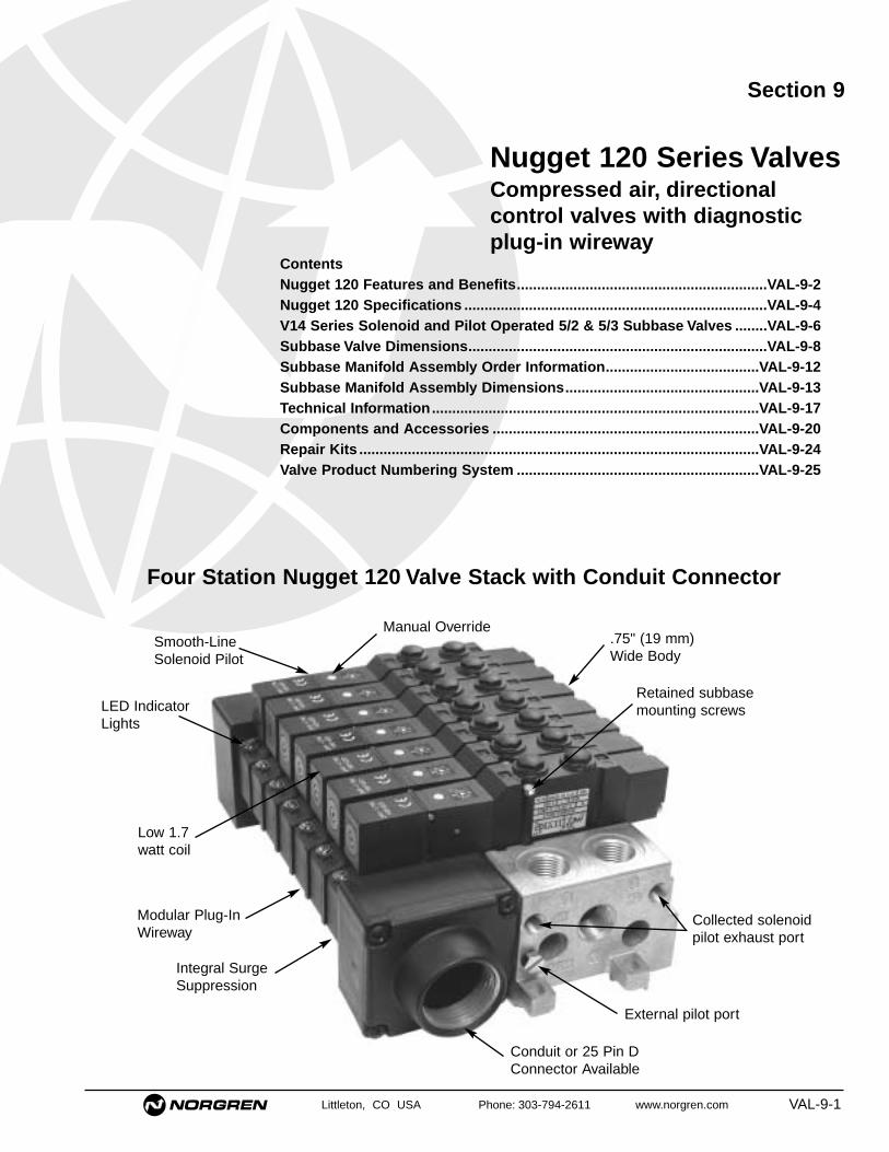
Littleton, CO USA Phone: 303-794-2611 www.norgren.com VAL-9-1
Section 9
LED IndicatorLights
External pilot port
Collected solenoidpilot exhaust port
Smooth-LineSolenoid Pilot
Modular Plug-InWireway
Integral SurgeSuppression
Low 1.7watt coil
Retained subbasemounting screws
Nugget 120 Series ValvesCompressed air, directionalcontrol valves with diagnosticplug-in wireway
ContentsNugget 120 Features and Benefits..............................................................VAL-9-2Nugget 120 Specifications ...........................................................................VAL-9-4V14 Series Solenoid and Pilot Operated 5/2 & 5/3 Subbase Valves ........VAL-9-6Subbase Valve Dimensions..........................................................................VAL-9-8Subbase Manifold Assembly Order Information......................................VAL-9-12Subbase Manifold Assembly Dimensions................................................VAL-9-13Technical Information.................................................................................VAL-9-17Components and Accessories ..................................................................VAL-9-20Repair Kits ...................................................................................................VAL-9-24Valve Product Numbering System ............................................................VAL-9-25
Conduit or 25 Pin DConnector Available
Four Station Nugget 120 Valve Stack with Conduit Connector
Manual Override.75" (19 mm)Wide Body

VAL-9-2
Nugget 120 Series Valves
The Nugget 120 Valve – Ideally suited for applicationsdesigned around low cost PC's coupled with small electro-pneumatic interface modules. Ideal for the limitedspace available in today's control cabinets.Two Year Unconditional WarrantyAll Nugget 120 valves are warranted to be free from defectsfor a full two years from the date of purchase. This extendedwarranty period provides users with a valuable guarantee ofquality and service.Compact DimensionsSubbase valves are .75" (19 mm) wideand 5.51" (140 mm)long in a single solenoid pilot configuration.Thin Lip Seal SpoolNorgren Nugget 120 valves feature a lightweight, one-piecealuminum spool and nitrile seal assembly. Shifting forces areminimized to 29 psig (2.0 bar) for single solenoid by the lowinertial spool made from high strength anodized aluminum.The one piece spool and seal assembly is easily serviced,resulting in cost savings during maintenance. Durable lowfriction lip seals are designed to operate with lubricated ornon-lubricated air, and can be used for multi-pressureapplications.Top Ported Subbase ValvesNugget 120 subbase mounted valves come standard with1/4" cylinder top ports. The ports are shipped plugged withattractive plastic acorn nut style pipe plugs. These ports maybe employed to provide a number of customer benefits. Thesubbase valve top ports may be plumbed with pressureindicators to show the position of the spool. These full flowports may also be used as a plumbing convenience whentwo pieces of equipment are actuated simultaneously. Finally,top porting offers the user a third porting orientation whencombined with side or bottom ported subbases.Fixed Length ManifoldThe Nugget 120 subbase valve can be mounted on a fixedlength manifold with the use of an optional seal. This featureallows the user to mount one valve on either the standardmodular subbase or the economical fixed length manifold.Retained Subbase Mounting ScrewsAll Nugget 120 subbase valves are assembled with the twosocket head cap mounting screws retained in the valve body.This feature prevents loss of the mounting screws duringassembly or maintenance.Collected Pilot Exhaust on Subbase ValvesExhaust from each solenoid pilot operator mounted to amodular subbase manifold is routed to a single exhaust porton the manifold end plate. This makes routing of exhaust airvery easy when potential contamination of the product is anissue.
Pre-lubricated for LifeDuring assembly, every Nugget 120 spool is pre-lubed for the life* of the valve. This allows non-lubricated air service.*(Approximately 20 million cycles of lubricated airservice. Non-lubricated air will reduce the numberof cycles.)
High-flow DesignImprovements to body and base design combine tosubstantially increase flow. Base galleries linked tothe aluminum die cast body combine with deepcavities to provide flow levels comparable to muchlarger 1/4" NPT size valves. 5/2 valves have a Cv of1.17, and 5/3 valves have a Cv of 0.79.
Port and Operator IdentificationEach of the ports is identified by a permanentnumber adjacent to the port on the body or subbase.In addition, a two-digit number at each end of thevalve body indicates the ports connected when theoperator is actuated. Port and operator identificationon all Nugget 120 valves comply with ANSI/(NFPA)T3.21.15-1989.Quality AppearanceNorgren's matte black color gives any control circuitinstallation a quality appearance, reflecting thesuperior operating capability built into every Nugget120 Valve.Operator OptionsSolenoid pilot and air pilot operators are available forprimary actuation and secondary return operation.Spring return operators are also available for returnoperation.
Rotatable Connector and CoilThe cable grip connector can be rotated in 90°increments, and the solenoid pilot coil can be turnedin increments of 180°, making the operatorsadaptable for easy installation.
Electrical Connector OptionsOptions include a 10-foot, three-conductor, moldedcable with or without LED and surge protection.
Valve AccessoriesPressure Indicators can be plumbed into the subbase valves' top ports to show the relativeposition of the spool. This feature decreases downtime by increasing diagnostic capability.
Blanking plates are available for covering unusedstations on subbase manifolds, making manifoldexpansion easy.
Intermediate Supply/Exhaust Plates are used tointroduce additional pressures to, or control exhaustfrom, manifolds simplifying plumbing in complexpneumatic circuits.
Littleton, CO USA Phone: 303-794-2611 www.norgren.com

All Dimensions in Inches (mm)
Littleton, CO USA Phone: 303-794-2611 www.norgren.com VAL-9-3
Nugget 120 Series Valves
Blanking Plugs and Gaskets can be employedto isolate multiple pressures or direct exhaust.
DIN Rail MountingNugget 120 modular manifolds can be mountedto DIN rails; OEM's building machines for exportcan take advantage of this feature.
Three Mounting Styles AvailableSubbase Valves are attached to subbasemodular manifolds with two socket head capscrews, which reduces the potential for leaksand allows quick assembly of valves tomanifolds. Porting for common inlet, exhaust,external pilot and collected solenoid pilotexhaust are located in the end plates. Cylinderporting is located in the subbases. Both endplates and subbases are available either side orbottom ported. Inlet ports are 3/8" PTF or ISOG. Cylinder and exhaust ports are 1/4" PTF orISO G. External pilot and collected solenoidexhaust ports are 10-32 UNF or M5. Thesemanifolds may also be mounted with the Nugget120 Wireway.
A single subbase valve is attached to a SingleSubbase with two socket head cap screws,providing easy installation. Inlet, exhaust,external pilot supply, and cylinder ports arelocated on the sides or bottom of the subbase.Inlet, cylinder and exhaust are 1/4" PTF or ISOG. External pilot ports are 10-32 UNF or M5.
Subbase, Fixed Length Manifolds usestandard subbase mounted valves and adifferent seal to produce an economicalmanifold. For quick installation andmaintenance, valves are attached to themanifold with two socket head cap screws.Valves share common supply and exhaustgalleries in the manifold. Nugget 120 subbasetop ports are utilized for output to theapplication. The optional pressure indicators arenot available for use with subbase fixed lengthmanifolds.
Nugget 120 Wireway FeaturesNugget 120 wireways are available with a 25-Pin Dconnector, Round IP-65 connector, or a 1" conduit electricalconnector. All share the following cost and work savingfeatures:● The single wire for each solenoid pilot means lower
installation cost and easier trouble shooting.● Wireways feature modular circuit boards with solid state
design. These boards plug into each other providing up toan 16-station manifold for 25-pin electrical connection, ora 16-station manifold for a 1" conduit connection.
● Surge suppression and LED indicators are standard onall wireway modules providing protection to controllingdevices.
● 24 VDC Diagnostic/ Power Saving Option senses complete solenoid pilot plunger travel. LED's turn amber ifa fault is detected. Coils run cooler due to 50% powerreduction upon actuation. All these features add up tosimplified trouble shooting, less downtime, and a moreefficient valve stack.
● Nugget 120 offers a 1" conduit version which is ratedNEMA 4. Terminal connectors are made with WAGO®
Quick Clips for reduced installation time.● Low 1.7 Watt coils consume less power and generate
very little heat. These coils allow users to operate equipment more efficiently and safely.
● Nugget 120 wireways offer a wide range of voltagesincluding: 12 VDC, 24 VDC, 110-120V 50/60 Hz, 220-240V 50/60Hz., and are continuous duty rated.

VAL-9-4 Littleton, CO USA Phone: 303-794-2611 www.norgren.com
Nugget 120 Series Valves
SpecificationsFluids: Filtered and lubricated or non-lubricated compressed air.Operation: Thin lip seal spool valve, solenoid pilot or air
pilot actuated.Inlet Pressure Ranges
Solenoid Pilot Operated Valves* –With Internal Pilot Supply:
18 to 150 psig (1.2 to 10.3 bar)With External Pilot Supply:
26" Hg to 150 psig (26" Hg to 10.3 bar)**Air Pilot Operated Valves:
26" Hg to 150 psig (26" Hg to 10.3 bar)*** Solenoid pilot operators must be externally piloted if the supply pressure
to the main valve is below the minimum pilot pressure listed in the tablebelow.
** With vacuum source plumbed to an exhaust port, and 135 psig (9.3bar) maximum at inlet port.
Operating Pilot Pressures –Maximum Pressure: 150 psig (10.3 bar)
MountingSubbase valve: through holes to subbase and
manifold.Manifold Mounted: through holes in end plate or to a
35 mm DIN rail.Average Flow Factor (Cv)*
5-port, 2-position : 1.175-port, 3-position: 0.79
*Flow rating determined in accordance withANSI/NFPA/T3.21.3, Pneumatic Fluid Power FlowTest Procedure and Reporting Method, for fixedorifice components.
Solenoid Pilot Operator SpecificationsDuty: Continuous at 90% to 110% of rated voltage.Coil Type: Molded with three-pin, electrical plug-in
connector with 8 mm pin spacing. Conforms toDIN 43650, Form C.
Electrical Plug-in Connector: Cable grip for cablesup to 7/32" (5.6 mm) in diameter or with 10-ftmolded cable.
Enclosure Classification: NEMA 4, DIN 40050-IP65Wireway Enclosure Classification –
25-Pin D Connector: NEMA 1, IP40Round Connector: IP651" Conduit Connector: NEMA 4, IP65
Override: Non-locking or combination.Materials of ConstructionValve Materials –
Body, pistons, spool, subbases, manifolds: aluminumEnd Caps: nylon or polyphenyleneSolenoid Adapters: polybutyleneSpool Seals: hydrogenated nitrileGaskets: nitrile
Subbase Materials –End plates, subbase modules, and manifold:aluminum
Wireway Materials –Wireway housings, modules, and manifolds:glass filled nylonConduit end caps: zinc
Response Times** @ 132 psig (9 bar)
mSecType On Off
Solenoid pilot/ Spring 17 30Solenoid pilot/Solenoid pilot 17 17
**Response times are based on start of pressure change at outlet port. For other operating pressures contact factory.
Minimum Pilot PressuresMinimum Operating
PressurePrimary Secondary (return) psig (bar)Operator Operator 2-position 3-position
Air Pilot Air Pilot 18 (1.2) 38 (2.6)Large Air Pilot Small Air Pilot 18 (1.2) –Air Pilot Spring 29 (2.0) –Solenoid Pilot Solenoid Pilot 18 (1.2) 38 (2.6)Solenoid Pilot Spring 29 (2.0) –
Pressure Indicators –Minimum indicator pressure: 44 psig (3 bar)
Operating Temperatures –Air Pilot Operated Valves: -4°F to 176°F (-20°C to 80°C)†Solenoid Pilot Operated Valves: -4°F to 122°F (-20°C to 50°C)†
† With a dew point of supply air less than air temperature below 35°F(2°C)
Port Size
Subbase valve top ports1/4" NPT or ISO G
Subbase End PlatesInlet – 3/8" NPT or ISO GExhaust – 1/4" NPT or ISO GExternal Pilot and collected solenoid pilot exhaust – 10-32 UNF or M5.Subbase, Modular manifold cylinder ports – 1/4" NPT or ISO GAir Pilot Ports – 1/8" NPT, 10-32 UNF, or M5

Nugget 120 Series Valves
Littleton, CO USA Phone: 303-794-2611 www.norgren.com VAL-9-5
A End Plate assembly (left end)B Wireway Tie RodC DIN RailD Wireway Spacer (spacers are included in Wireway End Plate Kits)E Wireway ModuleF Gaskets (included with Wireway Module)G O-ringH Wireway End Plate (included in End Plate and Harness Assembly Kit) (Right End)J NutK End Plate assembly (right end)L Mounting screwsM Valve AssemblyN Coil terminal seal and screw (included with Wireway Module)P GasketQ Subbase ModuleR One Inch Conduit Wireway End Plate and Harness assembly (Left End)S NutT Subbase Tie Rods
GH
J K
L M
N
P
Q
R
Station 1
S
T
A
B
C
D
E
F
Exploded View of a Nugget 120 with Plug-inWireway and 1" Conduit Connector

VAL-9-6 Littleton, CO USA Phone: 303-794-2611 www.norgren.com
4 2
5 1 3
14 12
4 2
5 1 3
14 12
4 2
5 1 384 82
12/14
14 12
4 2
5 1 3
14 12
4 2
5 1 31214
4 2
5 1 312
14
4 2
5 1 3121484
4 2
5 1 3
1214
Nugget 120 Series Valves
● High flow compact valves.
● Subbase valves with top porting.
● Light weight, long life corrosionresistant materials.
● Available with common wireway.
● Flexible single station expansion.
● Low 1.7 watt coils.
Solenoid and Air Pilot Actuated5/2 & 5/3 Subbase Valves
Pilot Supply 1 4 End 1 2 End Weight MountingSymbol Model Gasket Type1 Operator Return lb. (kg) Option
5/2 Solenoid Pilot Actuated Subbase Valves
†
†
NOTES: All wireway valve numbers must end with an “A”, signifying no connector, i.e. V14R517A-B318ADouble solenoid valves for wireway applications require two manifold stations. Insert a “P” in position 8, e.g. V14R511P-B318A.
1 Gasket type supplied with the valve. For details see p.VAL-9-26.
† Minimum pressure to port 5 must be 18 psig (1.2 bar)
V14R5EEA-B318B Independent Solenoid Solenoid .53 (.24) Single subbase andExternal (Y) fixed length manifold
V14R517A-B318B Internal (W) Solenoid Spring .34 (.16) All bases
V14R527A-B318B External (X) Solenoid Spring .34 (.16) ModularSubbases
V14R5F7A-B318B Internal Twin Solenoid Spring .34 (.16) Single subbase and Supply (Z) fixed length manifold
V14R5E7A-B318B Independent Solenoid Spring .37 (.17) Single subbase andExternal (Y) fixed length manifold
V14R511A-B318B Internal (W) Solenoid Solenoid .49 (.22) All bases
V14R522A-B318B External (X) Solenoid Solenoid .49 (.22) ModularSubbases
V14R5FFA-B318B Internal Twin Solenoid Solenoid .49 (.22) Single subbase and Supply (Z) fixed length manifold
Valves listed in the table below include 1/4" PTF top cylinder ports, spring,pressure or solenoid return, 110-120V 50/60 Hz, non-locking override, internalpilot and cable grip connector. For voltage options see Voltage Codes Table onp. VAL-9-7. For other options see Valve Product Numbering System on pp. VAL-9-32.
Order Information

Nugget 120 Series Valves
Littleton, CO USA Phone: 303-794-2611 www.norgren.com VAL-9-7
4 2
14 125 1 3
4
5 1 3
2
14 12
4
5 1 3
2
14 12
4 2
5 1 3
14 12
4 2
5 1 3
14 12
4 2
5 1 3
14 12
Pilot Supply Valve 1 4 End 1 2 End Weight MountingSymbol Model Gasket Type1 Function* Operator Return lb. (kg) Option
5/3 Solenoid Pilot Actuated Subbase Valves
1 Gasket type supplied with the valve. For details see p. VAL-9-26.*Valve Function Designations: APB = All Ports Blocked, COE = Cylinder Ports Open Exhaust, COP = Cylinder Ports Open Pressure ‡ Minimum pressure to port 5 must be 18 psig (1.2 bar)Notes: For voltage options see Voltage Code Table below.NOTES: All wireway valve numbers must end with an “A”, signifying no connector, e.g. V14R517A-B318A
Double solenoid valves for wireway applications require two manifold stations. Insert a “P” in position 8, e.g. V14R511P-B318A.
‡
5/2 and 5/3 Air Pilot Actuated Subbase ValvesGasket Valve 1 4 End 1 2 End Weight Mounting
Symbol Model Type1 Function* Operator Return lb. (kg) Option
Voltage Codes Electrical Details for Solenoid OperatorsVoltage Codes Power Inrush/Hold12V d.c. 2 1.7 W24V d.c. 3 1.7 W24V 50/60Hz 4 4.1 / 2.9 VA110V 50/60Hz 8 3.5 / 2.5 VA240V 50/60Hz 9 3.5 / 2.5 VA
Voltage Tolerances: ±10%Rating: 100% Continuous DutyInlet Orifice: 0.8 mmElectrical Connection: DIN 43 650 table ‘C’Manual Override: V14R5--A-B11*A – No override
V14R5--A-B21*A – Push button, spring return with locking facilityV14R5--A-B31*A – Push button, spring return
Protection Class: NEMA 4, IP 65 (DIN 40 050)
V14R611A-B318B Internal (W) APB Solenoid Solenoid 0.50 (.23) All bases
V14R622A-B318B External (X) APB Solenoid Solenoid 0.50 (.23) ModularSubbases
V14R6FFA-B318B Internal Twin APB Solenoid Solenoid .0.50 (.23) Single subbase and Supply (Z) fixed length manifold
V14R711A-B318B Internal (W) COE Solenoid Solenoid 0.50 (.23) All bases
V14R722A-B318B External (X) COE Solenoid Solenoid 0.50 (.23) ModularSubbases
V14R811A-B318B Internal (W) COP Solenoid Solenoid 0.50 (.23) All bases
V14R822A-B318B External (X) COP Solenoid Solenoid 0.50 (.23) ModularSubbases
1 Gasket type supplied with valve. For details see p. VAL-9-26*Valve Function Designations: APB = All Ports Blocked, COE = Cylinder Ports Open Exhaust, COP = Cylinder Ports Open Pressure
NOTE: Insert the voltage code from the above table for the required voltage into position 12 of the valve model number.Example: To change V14B5EEA-B318A from 110-120V 50/60 Hz to 24 VDC, order V14B5EEA-B313A.
V14R8DDA-X0020 Internal (X) COP Air Air .22 (.10) All bases
V14R5D7A-X0090 Internal (W) – Air Spring .22 (.10) All bases
V14R5DDA-X0020 Extermal (X) – Air Air .22 (.10) All bases
V14R59DA-X0060 Internal Twin – Large Air Small Air .22 (.10) All basesSupply (Z)
V14R6DDA-X0020 Internal (W) APB Air Air .22 (.10) All bases
V14R7DDA-X0020 External (X) COE Air Air .22 (.10) All bases
4
5 1 3
214 12
4
5 1 3
2
84 8212/14
1214
4
5 1 3
214 12
4
5 1 3
214 12
4
5 1 3
2
84 8212/14
14 12
4 2 1214
5 1 3
4
5 1 3
2
84 8212/14
1214
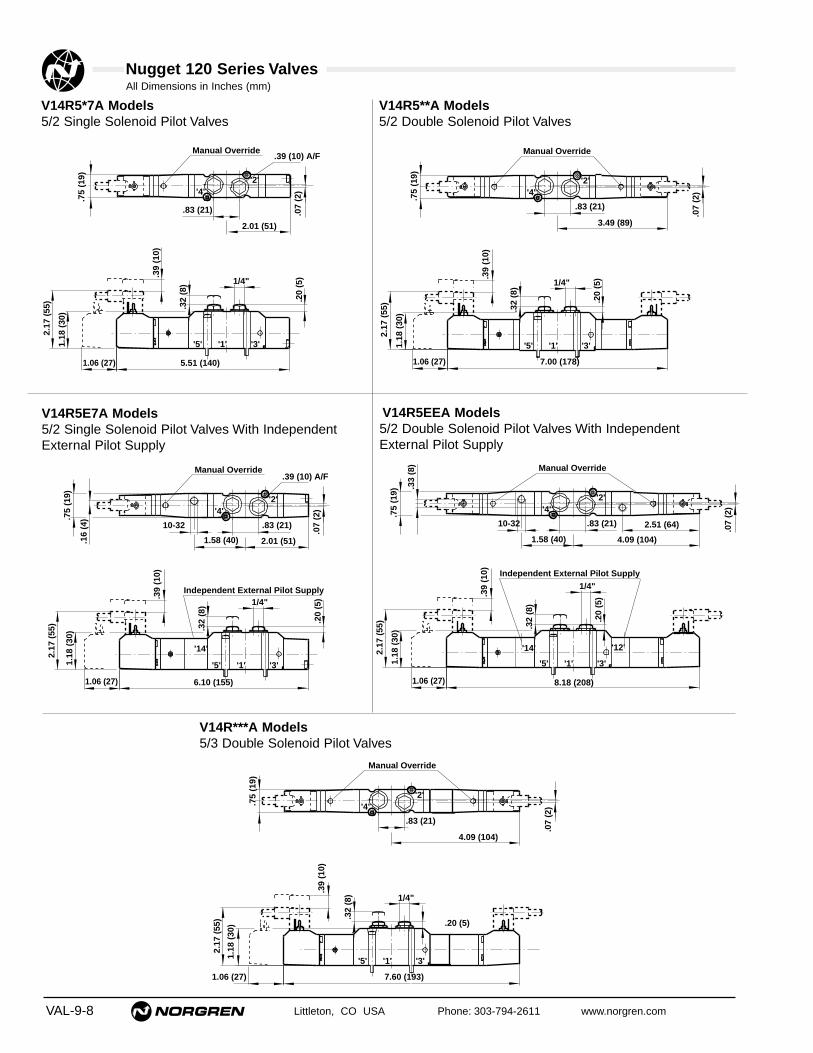
All Dimensions in Inches (mm)
VAL-9-8 Littleton, CO USA Phone: 303-794-2611 www.norgren.com
Nugget 120 Series Valves
V14R5*7A Models5/2 Single Solenoid Pilot Valves
.32
(8)
.07
(2)
.39
(10)
.75
(19)
5.51 (140)
2.17
(55
)
1.18
(30
)
.20
(5)
Manual Override
2.01 (51)
.83 (21)
'5' '1' '3'
'4''2'
1/4"
1.06 (27)
.39 (10) A/F
.32
(8)
.07
(2)
.39
(10)
.75
(19)
7.00 (178)
2.17
(55
)
1.18
(30
)
.20
(5)
Manual Override
3.49 (89)
.83 (21)
'5' '1' '3'
'4''2'
1/4"
1.06 (27)
V14R5**A Models5/2 Double Solenoid Pilot Valves
V14R5E7A Models5/2 Single Solenoid Pilot Valves With IndependentExternal Pilot Supply
V14R***A Models5/3 Double Solenoid Pilot Valves
.32
(8)
.07
(2)
.39
(10)
6.10 (155)
2.17
(55
)
1.18
(30
)
.20
(5)
Manual Override
2.01 (51)
.83 (21)
'5' '1' '3'
'4''2'
1/4"
.75
(19)
.16
(4)
1.58 (40)
Independent External Pilot Supply
1.06 (27)
10-32
.39 (10) A/F
'14'
.32
(8)
.07
(2)
.39
(10)
.75
(19)
8.18 (208)
2.17
(55
)
1.18
(30
)
.20
(5)
Manual Override
4.09 (104)
.83 (21)
'5' '1' '3'
'4''2'
1/4"
1.58 (40)
.33
(8)
2.51 (64)
Independent External Pilot Supply
1.06 (27)
10-32
'14' '12'
V14R5EEA Models5/2 Double Solenoid Pilot Valves With IndependentExternal Pilot Supply
.32
(8).3
9 (1
0)
7.60 (193)
2.17
(55
)
1.18
(30
)
Manual Override
.83 (21)
'5' '1' '3'
'4''2'
.20 (5)
.75
(19)
1/4"
1.06 (27)
.07
(2)
4.09 (104)

All Dimensions in Inches (mm)
Littleton, CO USA Phone: 303-794-2611 www.norgren.com VAL-9-9
Nugget 120 Series Valves
.32
(8)
.07
(2)
1.54
(39
)
5.51 (140)
1.18
(30
)
.20
(5)
Manual Override
2.01 (51)
'5' '1' '3'
'4''2'
1/4"
'4''2'
.83 (21)
1.06 (27)
.39 (10) A/F
V14R5**P Models5/2 Double Solenoid Pilot ValvesNote: Two manifold stations required
.32
(8)
.07
(2)
1.54
(39
)
6.10 (155)
1.18
(30
)
.20
(5)
Manual Override
2.60 (66)
'5' '1' '3'
'4''2'
1/4"
'4''2'
.83 (21)
1.06 (27)
.39 (10) A/F
V14R5D7A-X0090 5/2 Single Air Pilot Valves
.32
(8)
.07
(2)
.75
(19)
4.02 (102)
1.18
(30
)
.20
(5)
1.79 (46)
.83 (21)
.39 (10) A/F
'5' '1' '3'
'4''2'
1/4"
.06
(2)
10-32Pilot
2.01 (51)
'14'
.32
(8)
.07
(2)
.75
(19)
4.02 (102)
1.18
(30
)
.20
(5)
2.01 (51)
.83 (21)
'5' '1' '3'
'4''2'
1/4"
.12
(3)
.19 (5)
10-32
1.82 (46)
Pilots
'14' '12'
V14R**DA Models5/2 Double Air Pilot Valves
V14R*DDA Models5/3 Double Air Pilot Valves
.32
(8)
.75
(19)
4.61 (117)
1.18
(30
)
2.60 (66)
.83 (21)
'5' '1' '3'
'4''2'
1/4"
.12
(3) .0
7 (2
)
.19 (5)
10-32
1.82 (46)
Pilots
'14'
.20
(5)
'12'
V14R***P Models5/3 Double Solenoid Pilot Valves for Wireway Applications

All Dimensions in Inches (mm)
VAL-9-10 Littleton, CO USA Phone: 303-794-2611 www.norgren.com
Nugget 120 Series Valves
Single Subbase - Side Ported with Pilot Ports
1.81 (46)
1.57 (40)
.63
(16)
2.64 (67) .26 (7)
.75
(19)
1.50
(38
)
.24
(6)
1.10
(28
)
1/4" PTF
.90 (23) 1.12 (29)
3.15 (80)
.20
(5)
10-32 UNF
.55 (14)2.05 (52)
'5' '1' '3'
'4' '2'
'14' '12'
.37 (10) x
.28 (7) Deep
M6 x 1.0 x
.39 (10) Deep
.37 (10) x
.28 (7) Deep
M6 x 1.0 x
.39 (10) Deep
.24
(6)
Ports 1, 2, 3, 4, 5, 12 and 14 on sideSupplied with internal pilot supply gasket 10238-C01For twin supply valves, gasket No. 10239-C01 supplied with thevalves should be used.Weight: .52 lbs. (0.235 kg)
Single Subbase - Bottom Ported with Pilot Ports
1.81 (46)
1.57 (40)
1.34
(34
)
.51
(13)
1/4" PTF
.91 (23) 1.12 (29)
1.10
(28
)
3.15 (80)
2.64 (67) .26 (7)
.93
(24)
1.85
(47
)
.20
(5)
2.17 (55)
'1''5' '3'
'4' '2''14'
'12'
10-32 UNF
M6 x 1.0 x
.39 (10) Deep
.37 (10) x
.28 (7) Deep
1.54
(39
)
Ports 1, 2, 3, 4, 5, 12 and 14 on bottomSupplied with internal pilot supply gasket 10238-C01For twin supply valves, gasket No. 10239-C01 supplied with thevalves should be used.Weight: .52 lbs. (0.235 kg)
Port Size 1/4" PTF ISO GPart Number V10121-N01 V10121-G01
Port Size 1/4" PTF ISO GPart Number V10122-N01 V10122-G01

All Dimensions in Inches (mm)
Littleton, CO USA Phone: 303-794-2611 www.norgren.com VAL-9-11
Nugget 120 Series Valves
Fixed Length Manifold for Subbase Valves (with top port plugs removed)
.79 (20).59 (15)
3/8"
1/4"
1/4"
.40
(10)
1.45
(37
)
2.49
(63
)
1.18 (30)
.63 (16)
.89
(23)
1.12
(29
)
2.89
(74
)
A
.26
(7)
B (2 - 12 Stations).24 (6)
Note: Fixed Length Manifolds are supplied with internal pilot valve gaskets. For twin supplyvalves and intermediate supply/exhaust modules, use the gaskets supplied with thevalves and modules.
Part Number Number Weight PTF ISO G of Stations A B lbs. (kg)V10028-N01 V10028-G01 1 1.77 (45) - .34 (.168)V10028-N02 V10028-G02 2 2.76 (70) 2.28 (58) .54 (.257)V10028-N04 V10028-G04 4 4.33 (110) 3.86 (98) .88 (.40)V10028-N06 V10028-G06 6 5.91 (150) 5.4 (138) 1.19 (.54)V10028-N08 V10028-G08 8 7.48 (190) 7.0 (178) 1.52 (.69)V10028-N10 V10028-G10 10 9.1 (230) 8.58 (218) 1.85 (.84)V10028-N12 V10028-G12 12 10.63 (270) 10.16 (258) 2.21 (1.0)
.55 (14)
Blanking plugAllows multiple pressures in the same manifoldwhen used with fixed length manifolds.
10320-K01 3/8" supply port10320-K02 1/4" exhaust port

VAL-9-12 Littleton, CO USA Phone: 303-794-2611 www.norgren.com
Nugget 120 Series Valves
1
2 3
4
5
6
7 8
9 10
11
12 13
Product Family
Product Line andMounting Variation
Porting
Wireway Voltage
Number of Stations
Default
Number of stations for single pressure manifold
Wireway Connector
Function
02 to 20 stations = 25-pin D connector02 to 18 stations = Round IP-6502 to 16 stations = 1" PTF conduit
02 to 16 = Number of stations for single pressure manifold
XX = Single Pressure Application01 to 15 = Number of stations for dual
pressure into manifold
XX = Single Pressure Application01 to 15 = Number of stations for dual
pressure into manifold
X = Default X = Default
XX = No Wireway13 = 12 - 24 VDC w/surge protection18 = 120V-60 Hz, 110V/50 Hz w/surge protection19 = 240V/60 Hz, 220V/50 Hz w/surge protection
13 = 24 VDC
V=Valve Product
14 =Nugget 120, 5 port subbase
S = 3/8" PTFC = 3/8" ISO G
X = No WirewayA = 25-pin D connector (common negative)B = Round IP-65 (common negative)C = 1" PTF conduit (common negative)D = 25-pin D connector (common positive)E = Round IP-65 (common positive)F = 1" PTF conduit (common positive)
A = 25-pin D connector (common negative)B = Round IP-65 (common negative)C = 1" PTF conduit (common negative)
POSITION
A = Side ported, standard B = Side ported, 24 VDC diagnostic wireway
Ordering a Factory Assembled Nugget 120 Valve Modular Manifold1. Select the valve and voltage from pp. VAL-9-6/7, and indicate the station number on the base where each valve is to be
positioned. NOTE: Position 1 is referenced from the left hand end. See photo below.2. Select the base configuration using the following table as a guide.3. The maximum number of stations in any assembly is 16.
The following ordering example details the information needed to order the4-valve, single solenoid, 24 VDC, dual pressure manifold assembly shownat right.
One Nugget 120, 4-valve stack consisting of:Position Quantity Part No. Description
1-4 4 V14R517A-B313A Single Solenoid Valve1 V14SAC02-02X13 Manifold Assembly
NOTES: Product number includes blanking gasket between positions 2and 3.For additional accessories such as Blanking Plates see Components and Accessories p.VAL-9-27.
V 1 4 S B C 0 7 – X X X 1 3
Ordering Example
Left Hand End
Right Hand End

All Dimensions in Inches (mm)
Littleton, CO USA Phone: 303-794-2611 www.norgren.com VAL-9-13
Nugget 120 Series Valves
.54
(14)
.39
(10)
1.38
(35
)
1.05 (27)1.73 (44)
.54
(14)
1.38
(35
)
N x
.79
(20)
+ 3
.41
(87)
.79
(20)
.49 (12) .49 (12) .81 (21)
'4''2'
Left HandSide
Right HandSide
.24 (6)
.44 (11)
1.61 (41)
2.58 (66)
2.79 (71)
1.20 (31).83 (21)
.28
(7)
.56
(14)
.93
(24)
'1''5' '3'
'12/14' '82/84'
'4'
'2'
Bottom PortedModular Subbase
1/4"
Side PortedModular Subbase
2.33 (59)
.83 (21) .43 (11)
1/4"
‘4’‘2’
.42 (11)5.09 (129)
Bottom View
'4''2'
.55
(14)
.04
(1)
3.03 (77)
3.30
(84
)
.22
(6)
.2
2 (6
)
1/4"
3/8"
3/8"
Position 1
N = Number of Stations
G3 /
8
Modular Subbases for DIN rail or surface mounting

All Dimensions in Inches (mm)
VAL-9-14 Littleton, CO USA Phone: 303-794-2611 www.norgren.com
Nugget 120 Series Valves
Modular Subbase with 25-Pin D Sub-Connector Wireway for V14 valves
1.5
7 (
40
)
1/4
" ‘4’‘2’
‘4’‘2’
‘2’‘4’
‘2’‘4’
‘2’‘4’
2.33 (59)
2.2
4 (
57)
.74
(1
9)
G3 /
8
1.3
8 (
35
).7
9 (
20
).3
9(1
0)
2.12 (54)
.55
(1
4)
.04
(1
)
.22
(6
)
.54
(1
4)
1.3
8 (
35
)
N x
.7
9 (
20
) +
3.4
1 (
87
).2
2 (
6)
.54
(1
4)
1.73 (44)
5.55 (141)
1.05 (27)
.49 (12) .49 (12) .81 (21)
3.03 (77)
3.2
9 (
84
)
3/8"1/4"
.83 (21) .43 (11)
.42 (11)
LED
Side PortedModular Subbase
3.4
9 (
89
)
Left HandSide
Right HandSide
.24 (6)
.44 (11)
1.61 (41)
2.58 (66)
2.79 (71)
1.20 (31).83 (21)
.28
(7
)
.56
(1
4)
.93
(2
4) '1'
'5' '3'
'12/14' '82/84'
'4'
'2'
Bottom PortedModular Subbase
1/4
"
Bottom View
Position 1
3/8"
N = Number of stations

All Dimensions in Inches (mm)
Littleton, CO USA Phone: 303-794-2611 www.norgren.com VAL-9-15
Nugget 120 Series Valves
Modular Subbase with One Inch Conduit Entry Wireway for V14 valves
‘2’‘4’
‘2’‘4’
‘2’‘4’
1.38
(35
).7
9 (2
0).3
9(1
0)
.22
(6)
.54
(14)
1.38
(35
)
N x
.79
(20)
+3.
41 (
87)
.22
(6)
.54
(14)
1.73 (44)
5.55 (141)
1.05 (27)
.49 (12) .49 (12) .81 (21)
LED
Left HandSide
Right HandSide
1 2 3 4 5 6 7 8 9 10
111213141516C E
2.07
(53
)
1/4"
PT
F
‘4’‘2’
‘4’‘2’
2.12 (54)
.83 (21) .43 (11)
Side PortedModular Subbase
.24 (6)
.44 (11)
1.61 (41)
2.58 (66)
1.20 (31).83 (21)
.28
(7)
.56
(14)
.93
(24
) '1''5' '3'
'12/14' '82/84'
'4'
'2'
Bottom PortedModular Subbase
1/4"
3/8
Bottom View
2.79 (71)
2.24
(57
)
1" NPT
.55
(14)
.04
(1)
3.03 (77)
3.29
(84
)
1/4"
.42 (11)
3.49
(89
)
3/8"
1.12
(29
)
1.24 (32)
2.33 (59)
Position 1
1" conduit housing with conduit entry plate removed
showing quick connectsNote: Maximum wire size for
conduit entry connectors is 12 AWG (2.5 mm2)
G3 /
8

All Dimensions in Inches (mm)
VAL-9-16 Littleton, CO USA Phone: 303-794-2611 www.norgren.com
Nugget 120 Series Valves
0.24 (6)
0.44 (11)
1.61 (41)
2.58 (66)
2.79 (71)
0.22 (29)0.83 (21)
0.28
(7)
0.56
(14
)
0.94
(24
) '1''5' '3'
'12/14' '82/84'
Bottom View
'2'
'4'
G1/4 Side PortedSub-base Modules
G1 /
4
G3/8
G1/
4 o
r Ø
8 P
IF
G3/8G1/4
2.24
(57
)
3.03 (77)
3.29
(84
)
0.39 (10)
3.49
(89
)
A C
‘4’‘2’
‘4’‘2’
‘4’‘2’
1.38
(35
)0.
80(2
0)0.
41(1
0)
0.22
(6)
0.54
(14)
1.38
(35
)
N x
0.7
9 (2
0) +
3.4
1 (8
7)0.
22 (
6)
0.54
(14
)
1.73 (44)
5.43 (138)
1.05 (27)
0.61 (16) 0.61(16)
0.81 (21)
LED
B
Left HandSide
Right HandSide
1.92
(49
)
G3 /
8
0.49
(12
)
0.04
(1)
Modular Subbase with Round IP-65 Wireway Connector for V14 valves
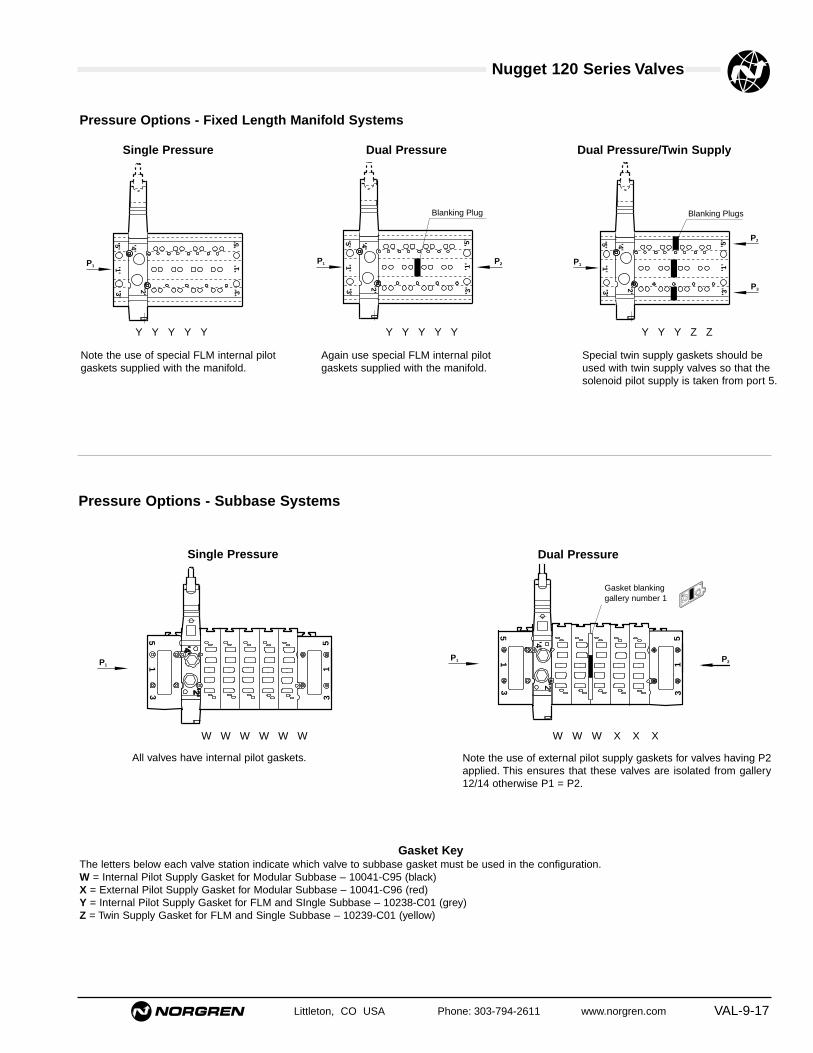
Nugget 120 Series Valves
Littleton, CO USA Phone: 303-794-2611 www.norgren.com VAL-9-17
'4''2'
'5''1'
'3' '3'
'1'
'5'
P1
'4''4'
'2''2'
P15
13 3
15 '4'
'2'
P1
51
3 31
5
P2
Gasket blanking gallery number 1
'4''2'
'5''1'
'3' '3'
'1'
'5'
P1 P2
Blanking Plug
'4''2'
'5''1'
'3' '3'
'1'
'5'
P1
P3
Blanking Plugs
P2
Pressure Options - Fixed Length Manifold Systems
Pressure Options - Subbase Systems
Single Pressure Dual Pressure
Single Pressure Dual Pressure
Dual Pressure/Twin Supply
Note the use of special FLM internal pilotgaskets supplied with the manifold.
Again use special FLM internal pilot gaskets supplied with the manifold.
Special twin supply gaskets should beused with twin supply valves so that thesolenoid pilot supply is taken from port 5.
Y Y Y Y Y Y Y Y Y Y Y Y Y Z Z
All valves have internal pilot gaskets. Note the use of external pilot supply gaskets for valves having P2applied. This ensures that these valves are isolated from gallery12/14 otherwise P1 = P2.
W W W X X XW W W W W W
Gasket KeyThe letters below each valve station indicate which valve to subbase gasket must be used in the configuration.W = Internal Pilot Supply Gasket for Modular Subbase – 10041-C95 (black)X = External Pilot Supply Gasket for Modular Subbase – 10041-C96 (red)Y = Internal Pilot Supply Gasket for FLM and SIngle Subbase – 10238-C01 (grey)Z = Twin Supply Gasket for FLM and Single Subbase – 10239-C01 (yellow)

Nugget 120 Series Valves
VAL-9-18 Littleton, CO USA Phone: 303-794-2611 www.norgren.com
'4''2'
P1
51
3 31
5 P2
Gasket blanking galleries 1, 3 and 5
P3
'4''2'
P1
51
3 31
5 P2
Gaskets blanking galleries 1, 3 and 5
P3
P4
Intermediate Supply Plate
P4
P5
'4''2'
P1
51
3 31
5 P2
Gasket blanking galleries 3 and 5
P3P1
'4''2'
P1
51
3 31
5 P2
Gasket blanking galleries 1, 3 and 5
P3
Gasket blanking gallery number 1
P4Intermediate Supply Plate
Dual Pressure/Twin Supply
2 x Twin SupplyTriple Pressure/2 x Twin Supply
Triple Pressure/Twin Supply
Here again note the use of external pilot gaskets for the same reasonas in Dual Pressure.
The internal pilot gaskets fitted to stations 1 and 2 ensureexternal supply via the 12/14 gallery to valve stations 3 to 6.
Valve/gasket combinations are as in Four pressure. All of the valves are external supply and a separate pilot connectionneeds to be made to 12/14 via the end plate port (s).
X X X X X XW W X X X X
W W X X X X
W W W X X X
Pressure Options - Subbase Systems

Nugget 120 Series Valves
Littleton, CO USA Phone: 303-794-2611 www.norgren.com VAL-9-19
Subbase Valve Surface Mounting Dimensions
'1' '2' '3'
'5' '4'
'12'
'14'
1.26 (32)
.72
(18.
2)
M3
'1' '2' '3''5' '4'
'12'
'14'
'84'
'82'
Black
'1' '2' '3''5' '4'
'12'
'14'
'84'
'82'
Red
'1' '2' '3'
'5' '4'
'12'
'14'
Black
'84
'82'
'1' '2' '3'
'5' '4'
'12'
'14'
'1' '2' '3'
'5' '4'
'12'
'14'
'84'
'82'
Yellow
Functional Valve GasketsThe information given below shows pilot supply flow path, gasket color, and the valve / base combinationsthe gaskets are used for. For modular subbase mounting, gaskets supplied with the valve must be used.For single station subbase and fixed length manifold mounting, gaskets supplied with the base must beused except for twin supply valves where gaskets supplied with the valve must be used.
V10041-C95 - Internal Pilot Supply GasketGasket type: W supplied with all internal pilot supply valves.
V10041-C96 - External Pilot Supply GasketGasket type: X supplied with all external pilot supply valves and pilot operated valves.
V10238-C01 - Internal Pilot Supply GasketGasket type: Y supplied with fixed length manifolds and single subbases.
V10239-C01 - Twin Supply GasketGasket type: Z supplied with all twin supplyvalves.
For Modular Subbase
For Fixed Length Manifold and Single Subbase
For Intermediate Supply Exhaust Module and Blanking Plate
White
V10356-C01 - ISEM/Blanking Plate GasketSupplied with Intermediate Supply Exhaust Moduleand Blanking Plate
'1' '2' '3'
'5' '4'
'12'
'14'
'84'
'82'
'1' '2' '3'
'5' '4'
'12'
'14'
For Single Sub-base
V10381-C01 - External Supply Gasket
Red

Nugget 120 Series Valves
VAL-9-20 Littleton, CO USA Phone: 303-794-2611 www.norgren.com
1 2 3 4 5 6 7 8 9 10
111213141516C E
1" Conduit Housing with cover plate removed
1" conduit housing with conduit entry plateremoved to show the unique, easy to usequick connects.Note: Maximum wire size for the conduit entryconnectors is 12 AWG (2.5 mm2)C = Common negativeE = Ground
0.31 (8) 0.9 (23)
0.8
(19)
3/8 PIF
2.4
(61)
2.5
(64)
2.1 (53)0.9 (24)
0.43 (11) 0.83 (21)
0.75
(19
)2.
40 (
61)
2.52
(64
)
2.08 (53)24
3/8 PIF
1.30 (33)
1.34
(34
)
.71 (18)
Pressure Regulator BlockV14B517A-Q2113 DualV14B517A-Q2116 Mono port 2V14B517A-Q2119 Mono port 4
Pressure Gauge Kit for RegulatorV14B517A-Q2120 DualV14B517A-Q2121 Mono
Flow Control BlockV14B517A-Q2211 (3/8 OD PIF)
LED's
2.5 (63)
.40
(10)
2.17
(55
)35
x
Nugget 120 end plate 4 outputs VE1MP14B-00400
Remote Output Modules
Application:Remote output modules are used with Nugget 40 and Nugget 120valve manifolds to provide up to 4 outputs to remote devices such asSoft Start and Monitored Dump Valves. Harness assemblies shouldbe increased by the relevant number of stations.
All Dimensions in Inches (mm)

Nugget 120 Series Valves
Littleton, CO USA Phone: 303-794-2611 www.norgren.com VAL-9-21
V10249-K00Wireway Spacer
Wireway End Plate and Harness Kit with 25-Pin DsubconnectorV14B517R-Q0604 4 stationsV14B517R-Q0608 8 stationsV14B517R-Q0612 12 stationsV14B517R-Q0616 16 stationsV14B517R-Q0620 20 stations
Wireway End Plate and Harness Kit with 1" conduitconnector V14B517R-Q0804 4 stationsV14B517R-Q0808 8 stationsV14B517R-Q0812 12 stationsV14B517R-Q0816 16 stations
Wireway ModuleV14B517R-Q0913 12-24 VDC with indicator, common
negativeV14B517R-Q0918 110-120V 50/60 Hz w/indicatorV14B517R-Q0919 220-240V 50/60 Hz w/indicatorV14B517R-Q09B3 24 VDC Diagnostic / Power Saving,
common negativeV14B517R-Q0953 12-24 VDC w/indicator, common
positive
Tie rod kits w/ fastenersV14B517A-Q03** M3 For wirewayV14B517A-Q04** M5 For subbase** Insert number of stations 02-16 stations
Modular subbase* – Single station manifold block.V14B517R-Q010N Side ported 1/4" PTFV14B517R-Q010G Side ported 1/4" ISO G
*Includes side gasket.
End Plate KitV11273-N01 Side ported 3/8" PTFV11273-G01 Side ported 3/8" ISO G
Note: See p. VAL-9-5 for component reference locations
NOTE: Kits include (1) fixed length tie rod andfasteners. Subbases require (2) kits per manifold, andwireways require (1) kit per manifold. Length isdetermined by the number of stations to be manifolded.

Nugget 120 Series ValvesAll Dimensions in Inches (mm)
VAL-9-22 Littleton, CO USA Phone: 303-794-2611 www.norgren.com
.02
(.45
)
.72
(18)
.75
(19)
.59 (15)
1.26 (32)
2.44 (62)
.16
(4)
M3 X 0.5
.23
(6)
.20 (5)
.02
(.45
)
.39
(10)
.72
(18)
.75
(19)
.59 (15)1.46 (37)
1.26 (32)
.34
(9)
.61
(16)
1/4"
M3 X 0.5
.23
(6)
.63 (16)
'5'
'1' '3'
2.44 (62)
Blanking Plate KitInstalled in place of a valve to allow an additionalvalve to be added at a later date.V14B517A-Q2700
Intermediate Supply/Exhaust platekitUsed to introduce additional pressure orexhaust air flow within a valve stack.Part Number Port Form
V14B517A-Q240N 1/4" PTFV14B517A-Q240G 1/4" ISO G
Pressure Indicator
V14B517AQ28001/4" port plug with integral pressure indicator. Replacesstandard port plugs. Minimum 44 psig (3 bar) operatingpressure.
.39 (10) flats
1/4" NPT
Rotowink Indicator Kit40000-K30 Red indicates unactuated, green indicates actuated.40000-K31 Green indicates unactuated, red indicates actuated.Spring-loaded pressure-actuated device indicates through theuse of two contrasting fluorescent colors the presence orabsence of air pressure at the cylinder port. Kits include 1/8"and 1/4" bushings for installation. Minimum 10 psig (0.7)operating pressure.
A
B
C
Blanking Gasket SetV10040-K96 .01 lbs. (.006 Kg)
For dual or Multi-pressure Supply on Modular Sub-base.Set of 3 sub-base to sub-base gaskets for blanking port 1,ports 3 & 5 or ports 1,3 & 5.
1.82 (46)
.78
(20)
Dia
.
1/8" NPT
Description Part Number(A) Gasket for blanking ports 1, 3 and 5 V10040-C98(B) Gasket for blanking port 1 V10040-C97(C) Gasket for blanking ports 3 and 5 V10040-C96
Wireway End Plate and Harness Kit with IP65 RoundConnector ConnectorV14B517R-Q0704 4 stationsV14B517R-Q0708 8 stationsV14B517R-Q0712 12 stationsV14B517R-Q0716 16 stations

Nugget 120 Series ValvesAll Dimensions in Inches (mm)
Littleton, CO USA Phone: 303-794-2611 www.norgren.com VAL-9-23
1.70
(43
).10 (2).71 (18)
.60 (15)
DIN Rail Mounting Kit10319-K30 .02 lbs. (.008 Kg)Kit for mounting side ported modular sub-bases onDIN 46277-3, BS5584 and CENELEC EN 50.022 mounting rail.
.29 (7)
1.38 (35)
DIN-railV10009-C00 .69 lbs. (.312 Kg)39" (1 meter) length.
13
12
11
10
9
8
7
6
5
4
3
2
25
24
23
22
21
20
19
18
17
16
15
141
A
.98 (25)
Socket View from front
Type: 25 pin IP 40 D Sub-connector. Cable size 20 AWG (.52 mm2)
Model A Weight (Kg)
V10020–E01 3' (1m) .61 lbs. (.28)
V10020–E03 10' (3m) 1.50 lbs. (.68)
V10020–E05 16' (5m) 2.38 (1.08)
D Sub-Connector with Cable
Pin no. Socket Plug Pin no. Socket Plug1 Solenoid 1 Red 14 Solenoid 14 Green/red2 Solenoid 2 Blue 15 Solenoid 15 Yellow/red3 Solenoid 3 Green 16 Solenoid 16 White/red4 Solenoid 4 Yellow 17 Solenoid 17 Red/black5 Solenoid 5 White 18 Solenoid 18 Red/brown6 Solenoid 6 Brown 19 Common,-negative Yellow/blue7 Solenoid 7 Violet 20 Common,-negative White/blue8 Solenoid 8 Orange 21 Common,-negative Blue/black9 Solenoid 9 Pink 22 Common,-negative Orange/blue10 Solenoid 10 Turquoise 23 Common,-ground Yellow/green11 Solenoid 11 Grey 24 Solenoid 19 White/green12 Solenoid 12 Red/blue 25 Solenoid 20 Orange/green13 Solenoid 13 Black
IP 40 D Sub-Connector
Solenoid No. 1 is nearest to the socket
0.79 (20)0.6 (1.5) 1.69 (43)
0.94
(24
)
0.94 (24) AF
3.23 (82) 0.98 (25)
‘A’
1.30
(33
)
0.28 (7)0.31 (8)
1.10
(28
)
Model A Weight (Kg)
V10021–E01 3 (1m) .75 (.34)
V10021–E03 10 (3m) 1.63 (.74)
V10021–E05 16 (5m) 2.51 (1.14)
V10021–E08 26 (8m) 4.67 (2.12)
V10021–E10 32 (10m) 5.89 (2.67)
Pin. Socket Plug Pin. Socket PlugA Solenoid 1 Red N Solenoid 13 BlackB Solenoid 2 Blue P Solenoid 14 Green/redC Solenoid 3 Green R Solenoid 15 Yellow/redD Solenoid 4 Yellow S Solenoid 16 White/redE Solenoid 5 White T Solenoid 17 Red/blackF Solenoid 6 Brown U Solenoid 18 Red/brownG Solenoid 7 Violet V Common,-negative Yellow/blueH Solenoid 8 Orange W Common,-negative White/blueJ Solenoid 9 Pink X Common,-negative Blue/blackK Solenoid 10 Turquoise Y Common,-negative Orange/blueL Solenoid 11 Grey Z Common, -ground Yellow/greenM Solenoid 12 Red/blue
IP65 ‘Round’ Connector
Type: 23 pin IP65 ‘Round’ connector. Cable size 20 AWG (.52 mm2)
Round Connector with Cable
Solenoid No. 1 is nearest to the connector on valve manifold
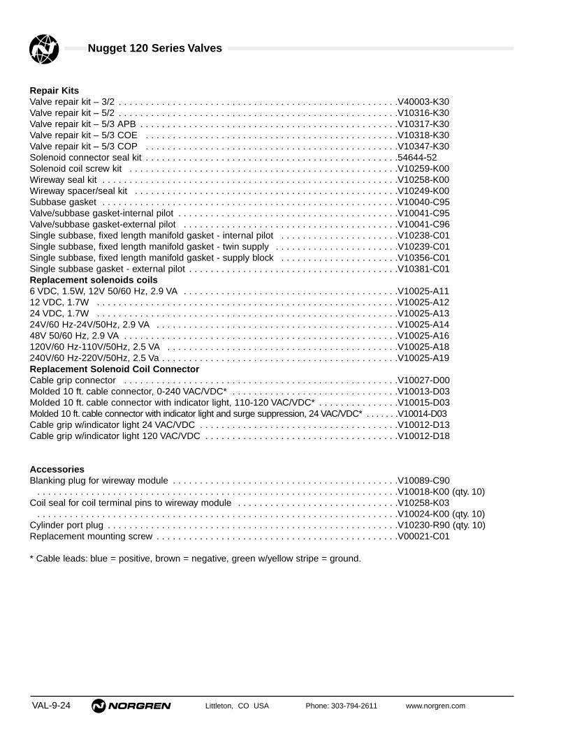
Nugget 120 Series Valves
VAL-9-24 Littleton, CO USA Phone: 303-794-2611 www.norgren.com
Repair KitsValve repair kit – 3/2 . . . . . . . . . . . . . . . . . . . . . . . . . . . . . . . . . . . . . . . . . . . . . . . . . . . .V40003-K30Valve repair kit – 5/2 . . . . . . . . . . . . . . . . . . . . . . . . . . . . . . . . . . . . . . . . . . . . . . . . . . . .V10316-K30Valve repair kit – 5/3 APB . . . . . . . . . . . . . . . . . . . . . . . . . . . . . . . . . . . . . . . . . . . . . . . .V10317-K30Valve repair kit – 5/3 COE . . . . . . . . . . . . . . . . . . . . . . . . . . . . . . . . . . . . . . . . . . . . . . .V10318-K30Valve repair kit – 5/3 COP . . . . . . . . . . . . . . . . . . . . . . . . . . . . . . . . . . . . . . . . . . . . . . .V10347-K30Solenoid connector seal kit . . . . . . . . . . . . . . . . . . . . . . . . . . . . . . . . . . . . . . . . . . . . . . .54644-52Solenoid coil screw kit . . . . . . . . . . . . . . . . . . . . . . . . . . . . . . . . . . . . . . . . . . . . . . . . . .V10259-K00Wireway seal kit . . . . . . . . . . . . . . . . . . . . . . . . . . . . . . . . . . . . . . . . . . . . . . . . . . . . . . .V10258-K00Wireway spacer/seal kit . . . . . . . . . . . . . . . . . . . . . . . . . . . . . . . . . . . . . . . . . . . . . . . . .V10249-K00Subbase gasket . . . . . . . . . . . . . . . . . . . . . . . . . . . . . . . . . . . . . . . . . . . . . . . . . . . . . . .V10040-C95Valve/subbase gasket-internal pilot . . . . . . . . . . . . . . . . . . . . . . . . . . . . . . . . . . . . . . . . .V10041-C95Valve/subbase gasket-external pilot . . . . . . . . . . . . . . . . . . . . . . . . . . . . . . . . . . . . . . . .V10041-C96Single subbase, fixed length manifold gasket - internal pilot . . . . . . . . . . . . . . . . . . . . . .V10238-C01Single subbase, fixed length manifold gasket - twin supply . . . . . . . . . . . . . . . . . . . . . . .V10239-C01Single subbase, fixed length manifold gasket - supply block . . . . . . . . . . . . . . . . . . . . . .V10356-C01Single subbase gasket - external pilot . . . . . . . . . . . . . . . . . . . . . . . . . . . . . . . . . . . . . . .V10381-C01Replacement solenoids coils6 VDC, 1.5W, 12V 50/60 Hz, 2.9 VA . . . . . . . . . . . . . . . . . . . . . . . . . . . . . . . . . . . . . . . .V10025-A1112 VDC, 1.7W . . . . . . . . . . . . . . . . . . . . . . . . . . . . . . . . . . . . . . . . . . . . . . . . . . . . . . . .V10025-A1224 VDC, 1.7W . . . . . . . . . . . . . . . . . . . . . . . . . . . . . . . . . . . . . . . . . . . . . . . . . . . . . . . .V10025-A1324V/60 Hz-24V/50Hz, 2.9 VA . . . . . . . . . . . . . . . . . . . . . . . . . . . . . . . . . . . . . . . . . . . . .V10025-A1448V 50/60 Hz, 2.9 VA . . . . . . . . . . . . . . . . . . . . . . . . . . . . . . . . . . . . . . . . . . . . . . . . . . .V10025-A16120V/60 Hz-110V/50Hz, 2.5 VA . . . . . . . . . . . . . . . . . . . . . . . . . . . . . . . . . . . . . . . . . . .V10025-A18240V/60 Hz-220V/50Hz, 2.5 Va . . . . . . . . . . . . . . . . . . . . . . . . . . . . . . . . . . . . . . . . . . . .V10025-A19Replacement Solenoid Coil ConnectorCable grip connector . . . . . . . . . . . . . . . . . . . . . . . . . . . . . . . . . . . . . . . . . . . . . . . . . . .V10027-D00Molded 10 ft. cable connector, 0-240 VAC/VDC* . . . . . . . . . . . . . . . . . . . . . . . . . . . . . . .V10013-D03Molded 10 ft. cable connector with indicator light, 110-120 VAC/VDC* . . . . . . . . . . . . . . .V10015-D03Molded 10 ft. cable connector with indicator light and surge suppression, 24 VAC/VDC* . . . . . . .V10014-D03Cable grip w/indicator light 24 VAC/VDC . . . . . . . . . . . . . . . . . . . . . . . . . . . . . . . . . . . . .V10012-D13Cable grip w/indicator light 120 VAC/VDC . . . . . . . . . . . . . . . . . . . . . . . . . . . . . . . . . . . .V10012-D18
AccessoriesBlanking plug for wireway module . . . . . . . . . . . . . . . . . . . . . . . . . . . . . . . . . . . . . . . . . .V10089-C90 . . . . . . . . . . . . . . . . . . . . . . . . . . . . . . . . . . . . . . . . . . . . . . . . . . . . . . . . . . . . . . . . . . .V10018-K00 (qty. 10)
Coil seal for coil terminal pins to wireway module . . . . . . . . . . . . . . . . . . . . . . . . . . . . . .V10258-K03 . . . . . . . . . . . . . . . . . . . . . . . . . . . . . . . . . . . . . . . . . . . . . . . . . . . . . . . . . . . . . . . . . . .V10024-K00 (qty. 10)
Cylinder port plug . . . . . . . . . . . . . . . . . . . . . . . . . . . . . . . . . . . . . . . . . . . . . . . . . . . . . .V10230-R90 (qty. 10)Replacement mounting screw . . . . . . . . . . . . . . . . . . . . . . . . . . . . . . . . . . . . . . . . . . . . .V00021-C01
* Cable leads: blue = positive, brown = negative, green w/yellow stripe = ground.

Littleton, CO USA Phone: 303-794-2611 www.norgren.com VAL-9-25
Nugget 120 Series Valves
1
2 3
4
5
7
8
9
10
11 12
Product Family
Product Line andMounting Variation
Porting
Coil Voltage
13 Electrical Connector
Default
Operator type
Solenoid Override
Secondary operator 1 2 end
Function
1 = Solenoid, internal supply2 = Solenoid, external supply7 = Spring ReturnD = Air pilotE = Independent external supplyF = Internal twin supply
A = DefaultP = Double solenoid for wireway
1 = No override2 = Push and turn locking3 = Push non-locking
B = Solenoid X = Air pilot
0 = 10-32 air pilotP = 1/8" PTF air pilot
00 - No coil12 = 12 VDC13 = 24 VDC14 = 24 VAC18 = 120V/60 Hz, 110V/50 Hz19 = 240V/60 Hz, 220V/50 Hz
02 = Double air06 = Air/Air priority09 = Air/spring
A = Solenoid without connectorB = Cable gripC = 10 ft. molded cable, 0-240 VAC/VDCH = Cable grip w/indicator light, 24
VAC/VDCJ = Cable grip w/ indicator light, 120
VAC/VDCL = 18" flying leads5 = 10 ft. molded cable with indicator light,
surge suppression, 24 VAC/VDC6 = 10 ft. molded cable with indicator light,
110V/50 Hz-120V/60Hz
0 = Default
V = Valve Product
14 = Nugget 120, 5 port subbase
R = 1/4 PTFB = ISO G 1/4
5 = 5/26 = 5/3 APB7 = 5/3 COE8 = 5/3 COP
6 Primary Operator 1 4 end
1 = Solenoid, internal supply2 = Solenoid, external supply9 = Air PriorityD = Air PilotE = Independent external supplyF = Internal twin supply
POSITION V 1 4 R 5 1 7 A – B 3 1 8 B


Littleton, CO USA Phone: 303-794-2611 www.norgren.com VAL-10-1
Nugget 200 SpoolValves
Solenoid, Air, Manual, andMechanically Operated
Pneumatic Valves. Availablein 1/4", 3/8", or 1/2" ports
Section 10
ContentsFeatures . . . . . . . . . . . . . . . . . . . . . . . . . . . . . . . . . . . . . .VAL-10-2Solenoid Pilot Actuated Inline and Stacking Valves . . . .VAL-10-4Air Pilot Actuated Inline and Stacking Valves . . . . . . .VAL-10-18Manual and Mechanical Actuated Inline
and Stacking Valves . . . . . . . . . . . . . . . . . . . . . . . .VAL-10-23Fixed Length Manifold . . . . . . . . . . . . . . . . . . . . . . . . . .VAL-10-32Special Instructions - Stacking Valves . . . . . . . . . . . . .VAL-10-34Product Numbering System . . . . . . . . . . . . . . . . . . . . .VAL-10-36
Stacking Valve with Junction Box Low Pressure Air Operator on Inline Valve
Manual Lever Operator

Nugget 200 Spool Valves
VAL-10-2 Littleton, CO USA Phone: 303-794-2611 www.norgren.com
Norgren Nugget 200 valves feature a lightweight, one-piecealuminum spool and nitrile seal assembly. Shifting forces areminimized because of the low inertial spool made from highstrength anodized aluminum. Highly durable low friction lip sealsare designed to operate with lubricated or nonlubricated air.
Rugged Solenoid, Air, Manual, or Mechanical OperatorsNugget 200's one hundred and twelve different operators aredesigned to last for millions of cycles. Bodies and operators aremade of precision machined, cast aluminum, zinc, PPA, or acetal.
High FlowAn inline Cv of 1.6 provides exceptionally high flow for its compactsize. This makes the Nugget 200 valve appropriate for a widerange of applications, from machine control systems to air linecontrol.
Segmented Latch Type DetentThe spool is held securely in place by a unique segmented detentwhich engages a lip on the piston.
Shock Absorbent BumpersValve life is extended because of substantial bumpers whichabsorb the shock and vibration of the rapidly shifting spool andpiston.
Port and Operator IdentificationEach of the ports is identified by a permanent number adjacent tothe port on both the body and end plates. In addition, on inlinevalves, a two-digit number at each end of the body indicates theports connected when the operator at that end is actuated.
A Wide Range of Valve AccessoriesNorgren offers a wide range of accessories for use with theNugget 200 valve, including valve body cover plates, mufflers,intermediate supply exhaust block, isolating plugs, solenoidexhaust filter nut and many more. These accessories allow cost-efficient customizing for your specific application.
Four Mounting StylesInline Valves mount directly to the air lineand are available with the followingfeatures:● 1/4", 3/8", or 1/2" PTF or ISO G ports.● 3-port/2-position, 5-port/2-position, or 5-port/3-position configurations. The 3-port/2-position configuration is not available with1/2" ports.Stacking Valve Assemblies are two ormore valves manifolded together with tierods and end plates. They are available witheither a common inlet port, independentexhaust ports, or with common inlet andexhaust ports located in the end plates.Features include:● 3/8" ports in the end plate. 1/4" or 3/8"cylinder ports in valve body.● 5-port/2-position or 5-port/3-positionconfigurations.Stacking Valve Assemblies with JunctionBox feature a plug-in solenoid operatorwhich allows the valve to be servicedwithout disturbing the electrical wires. Thesolenoid plugs into a terminal block in thejunction box, with a gasket to prevent entryof dust or moisture. They are available onlyin the common inlet and exhaust portsconfiguration. Other features are the sameas listed above for Stacking ValveAssemblies.All stacking valves mount onapproximately 1-1/4" centers reducinginstallation space requirements.Fixed Length Manifolds are available formost Nugget 200 1/4" and 3/8" inlinevalves. The fixed length manifold reducesplumbing and installation time. Thelightweight aluminum construction uses 3/4"PTF common inlet and exhaust ports.These manifolds are available in 2 to 10station lengths.
Durable FinishExternal surfaces are protected with an ovencured, epoxy resin paint which providesexcellent corrosion protection and chipresistance.
Stacking Valve with Junction Box

Nugget 200 Spool Valves
Littleton, CO USA Phone: 303-794-2611 www.norgren.com VAL-10-3
High Flow Pilot Exhaust OrificeOversize pilot exhaust orifice provides rapidreturn time when valve is deactuated.
Solenoid Diffuser PlugA diffuser plug is factory installed in everysolenoid pilot exhaust to help prevent entry ofcontaminants during shipping and normaloperation. It may be removed when minimumresponse times are desired.
Electrical Connector OptionsA cable grip connector with indicator light; a1/2" NPT conduit connector; and a 5-foot,three-conductor, molded cable with or withoutindicator light, surge protection and reversevoltage protection are available.
Aesthetic AppearanceNorgren's high luster black powder paint gives any control circuitinstallation the quality appearance reflecting the superioroperating capacity built into every Nugget 200 valve.
Low Watt Solenoid OptionsThe 120 VAC and 24 VAC solenoid operator options require only3.5-watts of power and the 115 VDC operator requires 3.4 watts.All other DC operators require only 2 watts of power, ideal forcomputer based control systems as well as industrial applicationswhere minimum energy consumption is desired.
Rotatable Connector and CoilThe standard cable grip electrical connector can be rotated 180°,the solenoid coil can be turned in increments of 90°, and thesolenoid operator housing can be turned in increments of 180°making the operators adaptable for easy installation.
Electrical Connector OptionsA cable grip connector with indicator light; a 1/2" NPT conduitconnector; and a 5-foot, three-conductor, molded cable with orwithout indicator light, surge protection and reverse voltageprotection are available.
Solenoid Manual OverridesStandard solenoid operators are furnished with locking manualoverrides to provide a means of shifting the valve without electricalpower. Optional solenoids without overrides and with nonlockingoverrides are available.
CSA Certified ValvesCompleted inline and stacking valve assemblies with certainoperators are CSA Certified. Stacking valves with junction box andindicator light are CSA Component Certified.
Internal or External Solenoid Pilot SupplyAll solenoid operated valves can be quickly converted from aninternal to an external pilot supply by interchanging the positionsof two interface seals and removing the external supply port pipeplug.
Low Pressure Air Operator on Inline Valve
Manual Lever Operator

VAL-10-4 Littleton, CO USA Phone: 303-794-2611 www.norgren.com
Nugget 200 Spool Valves
● Long lasting spool design
● High flow compact valves
● Four mounting styles: inline, stacking valveassemblies, stacking valve assemblies withjunction box, and fixed length manifold.
● Wide range of operators and voltages available
● Three functional types: available in 3/2, 5/2, and5/3 configurations
1/4", 3/8", and 1/2" Solenoid Pilot Actuated3/2, 5/2, & 5/3 Inline and Stacking Valves
Technical Data
Medium:Filtered and lubricated or non-lubricated compressed air or vacuum.
Operation:Spool valve solenoid pilot actuated.
Mounting:Stacking – through holes on manifold base.Inline – through holes in valve body.
Port Size:PTF – 1/4", 3/8", 1/2"ISO G – 1/4", 3/8" .
Operating Pressure:Maximum 150 psig (10.3 bar). For details see overleaf.
Operating Temperature:-20° to 120°F (-29° to 50°C)Consult Technical Service for use below 36°F (2°C).
Materials:Body: AluminumSpool: Anodized aluminumSolenoid Operator Base: plasticPlunger and spring: Stainless steelElastomers: Nitrile and special nitrile-based low-friction elastomers.Note: See Seal Compatibility p. VAL-10-5.
Ordering InformationTo order standard Nugget 200 valves with coils,quote model number from tables overleaf, e.g. order:K71DA00-K36-KV21W2 for a 5-port/2-position,single Solenoid Pilot Operated, Spring Return modelwith an internal pilot supply, fitted with a 24 VDCstandard wattage coil, and rotatable cable gripconnector and locking override.
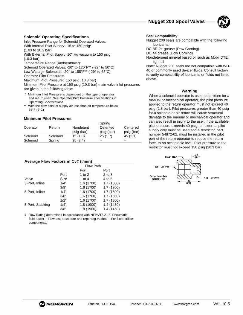
Nugget 200 Spool Valves
Littleton, CO USA Phone: 303-794-2611 www.norgren.com VAL-10-5
Seal CompatibilityNugget 200 seals are compatible with the following
lubricants:DC BR-2+ grease (Dow Corning)DC 44 grease (Dow Corning)Nondetergent mineral based oil such as Mobil DTE
light oilNote: Nugget 200 seals are not compatible with WD-40 or commonly used de-icer fluids. Consult factoryto verify compatibility of lubricants or fluids not listedabove.
Solenoid Operating SpecificationsInlet Pressure Range for Solenoid Operated Valves:With Internal Pilot Supply: 15 to 150 psig*(1.03 to 10.3 bar)With External Pilot Supply: 10" Hg vacuum to 150 psig (10.3 bar)Temperature Range (Ambient/Inlet):Solenoid Operated Valves: -20° to 120°F** (-29° to 50°C)Low Wattage Solenoids: -20° to 155°F** (-29° to 68°C)Operator Pilot Pressures:Maximum Pilot Pressure: 150 psig (10.3 bar)Minimum Pilot Pressure at 150 psig (10.3 bar) main valve inlet pressuresare given in the following table:
* Minimum Inlet Pressure is dependent on the type of operatorand return used. See Operator Pilot Pressure specifications inOperating Specifications.
** With the dew point of supply air less than air temperature below35°F (2°C)
Minimum Pilot PressuresSpring
Operator Return Nondetent Detented Centeredpsig (bar) psig (bar) psig (bar)
Solenoid Solenoid 15 (1.0) 25 (1.7) 45 (3.1)Solenoid Spring 35 (2.4) – –
Average Flow Factors in Cv‡ (l/min)Flow Path
Port PortPort 1 to 2 2 to 3
Valve Size 1 to 4 4 to 53-Port, Inline 1/4" 1.6 (1700) 1.7 (1800)
3/8" 1.6 (1700) 1.7 (1800)5-Port, Inline 1/4" 1.6 (1700) 1.7 (1800)
3/8" 1.6 (1700) 1.7 (1800)1/2" 1.6 (1700) 1.7 (1800)
5-Port, Stacking 1/4" 1.8 (1900) 1.4 (1450)3/8" 1.8 (1900) 1.4 (1450)
‡ Flow Rating determined in accordance with NFPA/T3.21.3, Pneumaticfluid power – Flow test procedure and reporting method – For fixed orificecomponents.
WarningWhen a solenoid operator is used as a return for amanual or mechanical operator, the pilot pressureapplied to the return operator must not exceed 40psig (2.8 bar). Pilot pressures greater than 40 psigfor a solenoid or air return will cause structuraldamage to the manual or mechanical operator andcan also result in injury to the user. If the availablepilot pressure exceeds 40 psig, an external pilotsupply only must be used and a restrictor, partnumber 54872-02, must be installed in the pilotport of the return operator to reduce the returnforce to an acceptable level. Pilot pressure to therestrictor must not exceed 150 psig (10.3 bar).
.81(21)
1/8 27 PTF
.33(8)9/16" HEX
1/8 27 PTF
54872 - 02Order Number

Nugget 200 Spool Valves
VAL-10-6 Littleton, CO USA Phone: 303-794-2611 www.norgren.com
Solenoid Operator Specifications
KVx/KUx, K0x/K1x, K2x/K3x, K4x/K5x, & K6x/K7x SeriesVoltages Available and Power Requirements:
Standard: 120V/60Hz-110V/50Hz: 7WOptional: KVx, K1x, K3x, K5x, & K7x Series
12V/60Hz/50Hz: 7W24V/60Hz/50Hz: 7W48V/60Hz/50 Hz: 7W240V/60Hz: 7W220V/50Hz: 7W12 VDC: 6W24 VDC: 6W
Low Wattage: KUx, K0x, K2x, K4x, & K6x SeriesStandard: 24 VDC: 2WOptional: 24V/50Hz/60Hz: 3.5W
120V/60Hz: 3.5W110V/50Hz: 3.5W6 VDC: 2W12 VDC: 2W115 VDC: 3.4W
Duty: Continuous at 90 to 105% of rated voltage
Coil Type: Class H. Molded with three-pin plug-in connector
Enclosure Classification: NEMA 4, per DIN 40050 – IP 65Connector Plug:KUx/KVx Series: Standard,Cable grip for cables 1/4" to 5/16"
(6 to 8 mm) in diameterK2x/K3x Series: Rotatable 1/2" Conduit ConnectorK4x/K5x Series: Class H. Molded with three-pin plug-in
connector
Override: Manual, locking
Pilot Supply: Internal - standard, External - optional
External Pilot Supply Port: 1/8" PTF (ISO G Optional).
Minimum Electrical Signal Duration: Solenoid operated 2-position detented or nondetented valves can be shifted with amomentary electrical signal. Minimum signal duration is 13 millisecondsfor single solenoid operated spring return valves. Double solenoidoperated valves minimum signal duration is 20 milliseconds.
Electrical connector spades on the operator coil are 3-pin with 11 mmspacing.
KDx & KQx SeriesVoltages Available and Power Requirements:
Standard: 120V/60Hz: 6WOptional: 24V/60Hz/50Hz: 6W
12VDC: 6W24VDC: 6W
Duty: Continuous at 85 to 105% of rated voltage
Coil Type: Class H. Molded with three-pins forelectrical connection or optional electrical plug-inconnector.
Enclosure Classification:NEMA 4, per DIN 40050 – IP 65Connector Plug: Cable grip for cables 1/4" to5/16" (6 to 8 mm) in diameter.
Electrical Connections –KD Series Operators: Furnished with 1/2" conduit connector molded into coil, leads are 18" longKQ Series Operators: Furnished without a connector
Override: Manual, locking or nonlocking.
Pilot Supply: Internal - standard, External - optional
External Pilot Supply Port: 1/8" PTF (ISO GOptional).
Minimum Electrical Signal Duration: Solenoidoperated 2-position detented or nondetentedvalves can be shifted with a momentary electricalsignal. Minimum signal duration is 13 millisecondsfor single solenoid operated spring return valves.Double solenoid operated valves minimum signalduration is 20 milliseconds.
Optional electrical connectors for KQx Seriesoperators conform to DIN43650 Form A for Three-Pin Electrical Connectors.
Electrical spades on the KQx Series operator coilare 3-pin with 18 mm spacing.
CSA Certified ValvesKDx and KQx Series solenoid operators are CSACertified. Optional solenoid coil voltages,solenoidcable grip electrical connectors and 1/2" NPTconduit electrical connectors also qualify for CSACertification.

Nugget 200 Spool Valves
Littleton, CO USA Phone: 303-794-2611 www.norgren.com VAL-10-7
KXx Series Hazardous Location Solenoid Voltages Available and Power Requirements
Standard: 120V/60Hz-100V/50Hz: 12WOptional: 240V/60Hz: 12W
208V/50Hz: 12W24V/60Hz: 12W22V/50Hz: 12W6 VDC: 12W12 VDC: 12W24 VDC: 12W48 VDC: 12W115 VDC: 12W
Duty: Continuous at 85 to 105% of rated voltage
Coil Type: Molded
Enclosure Classification: NEMA 7C, 7D, 8C, 8D, 9E,9F and 9G. Meets the requirements ofUnderwriters Laboratories for use in hazardouslocations as defined in National Electrical Code(ANSI CI-1975): Class I, Groups C & D; and ClassII, Groups E, F & G. Per DIN 40050 – IP 65.
Electrical Connection: Furnished with fixedconnection for 1/2" conduit.
Override: Manual, nonlocking - standard, locking -optional
Pilot Supply: internal - standard, external - optional
External Pilot Port: 1/8-27 NPTF
Exhaust Port: 1/4" NPT
Minimum Electrical Signal Duration: Solenoidoperated 2-position detented or nondetentedvalves can be shifted with a momentary air orelectrical signal. Minimum signal duration is 17milliseconds.
KMx Series Voltages Available and Power Requirements:
Standard: KMx: 120V/60Hz, 6WOptional: KMx: 24V/60Hz/50Hz, 6W
12VDC: 6W24VDC: 6W
Duty: Continuous at 85 to 105% of rated voltage.
Coil Type: Class H Molded with three-pin plug-in terminal block connector.KMx Series has an indicator light molded
into coil
Enclosure Classification: NEMA 1
Override: Manual, locking or nonlocking
External Pilot Supply Port: 1/8" PTF (ISO G Optional).
Minimum Electrical Signal Duration: Solenoid operated 2-position detentedor nondetented valves can be shifted with a momentary electricalsignal. Minimum signal duration is 13 milliseconds for single solenoidoperated valves. Double solenoid operated valves minimum signalduration is 20 milliseconds.
Electrical connectors conform to DIN43650 Form A for Three-PinElectrical Connectors.CSA Component Certified
Flow Chart1/4", 3/8" & 1/2" Ported Valves
SECONDARY PRESSURE EQUAL TO53% OF ABSOLUTE INLET PRESSURE
140
120
100
80
60
40
20
00
scfm
l/min
3600
3000
2400
1800
1200
600
Air
Flo
w
140120100806040200
0 654321 1110987
160 psig
barOutlet Pressure
25(1.7)
40(2.8)
60(4.1)
90(6.2)
120
(8.3)
150 psig
(10.3 bar)
Inlet
Pressure
Example –Find: Pressure drop
Given: Inlet pressure = 90 psigAir Flow = 50 scfm
Solution: Enter chart at 50 scfm and intersect with 90 psig inlet pressure line.Read outlet pressure = 80 psig.Pressure drop is equal to 90 minus 80 = 10 psig

Nugget 200 Spool Valves
VAL-10-8 Littleton, CO USA Phone: 303-794-2611 www.norgren.com
Solenoid Pilot Operated Inline Valves
PilotPort Pressure Weight Repair
Description Symbol Type Size Body* Operator psig (bar) lbs. (kg) Kit
Single 1/4" K41DA00 KS1-KV2 35 - 150 2.22 54237-59Solenoid 3-Port/ (2.4 - 10.3) (1.01)Spring 2-Position
3/8" K41EA00 KS1-KV2 35 - 150 2.22 54237-59Return (2.4 - 10.3) (1.01)
1/4" K71DA00 KS6-KV2 35 - 150 2.22 54237-56(2.4 - 10.3) (1.01)5-Port/ 3/8" K71EA00 KS6-KV2 35 - 150 2.22 54237-562-Position (2.4 - 10.3) (1.01)
1/2" K71FA00 KS6-KV2 35 - 150 4.40 54237-56(2.4 - 10.3) (2.00)Double 1/4" K41DA00 KV2-KV2 15 - 150 4.40 54237-59Solenoid 3-Port/ (1.0 - 10.3) (2.00)(Non- 2-Position
3/8" K41EA00 KV2-KV2 15 - 150 4.40 54237-59Detented) (1.0 - 10.3) (2.00)
1/4" K71DA00 KV2-KV2 15 - 150 2.22 54237-56(1.0 - 10.3) (1.01)5-Port/ 3/8" K71EA00 KV2-KV2 15 - 150 4.40 54237-562-Position (1.0 - 10.3) (2.00)
1/2" K71FA00 KV2-KV2 15 - 150 2.22 54237-56(1.0 - 10.3) (1.01)
1/4" K81DA00 KV0-KV0 15 - 150 4.40 54237-565-Port/ (1.0 - 10.3) (2.00)
3-Position 3/8" K81EA00 KV0-KV0 1.0 - 10.3 4.40 54237-56All Ports (15 - 150) (2.00)Blocked
1/2" K81FA00 KV0-KV0 15 - 150 4.40 54237-56(1.0 - 10.3) (2.00)
1/4" K81DA05 KV0-KV0 15 - 150 4.40 54237-575-Port/ (1.0 - 10.3) (2.00)
3-Position 3/8" K81EA05 KV0-KV0 15 - 150 4.40 54237-57Inlet Open (1.0 - 10.3) (2.00)to Cylinder
1/2" K81FA05 KV0-KV0 15 - 150 4.40 54237-57(1.0 - 10.3) (2.00)
1/4" K81DA06 KV0-KV0 15 - 150 2.22 54237-585-Port/ (1.0 - 10.3) (1.01)
3-Position 3/8" K81EA06 KV0-KV0 15 - 150 4.40 54237-58Cyl Open (1.0 - 10.3) (2.00)to Exhaust
1/2" K81FA06 KV0-KV0 15 - 150 4.40 54237-58(1.0 - 10.3) (2.00)Double 1/4" K41DA00 KVL-KVL 25 - 150 4.40 54237-59Solenoid 3-Port/ (1.7 - 10.3) (2.00)
(Detented) 2-Position3/8" K41EA00 KVL-KVL 25 - 150 4.40 54237-59(1.7 - 10.3) (2.00)
1/4" K71DA00 KVL-KVL 25 - 150 2.22 54237-56(1.7 - 10.3) (1.01)5-Port/ 3/8" K71EA00 KVL-KVL 25 - 150 2.22 54237-562-Position (1.7 - 10.3) (1.01)
1/2" K71FA00 KVL-KVL 25 - 150 2.22 54237-56(1.7 - 10.3) (1.01)
12 10
2
13
12
24
315
14
12
24
315
14
24
15 3
14 12
24
15 3
14 12
2
13
12 10
24
315
14 12
12
2
13
10
* Standard valves are equipped with PTF threads, solenoid operators with locking overrides, internal pilot, 120V/60 Hz-110V/50 Hz coils and cable grip connectors.Optional solenoid operators, coil voltages and electrical connectors can be ordered using the information on p. VAL-10-11/12. Solenoid specifications given on pp. VAL-10-6/7.
Note: For ISO-G threads, insert “G” in the 5th position. 1/2" ported bodies are not available with ISO G threads.
24
15 3
14 12

Nugget 200 Spool Valves
Littleton, CO USA Phone: 303-794-2611 www.norgren.com VAL-10-9
Solenoid Pilot Operated Stacking Valves
PilotPort Pressure Weight Repair
Description Symbol Type Size Body* Operator psig (bar) lbs. (kg) Kit
Single 5-Port/ 1/4" K78DA00 KS6-KV2 35 - 150 .53 54237-56Solenoid 2-Position (2.4 - 10.3) (.24)Spring Common 3/8" K78EA00 KS6-KV2 35 - 150 .53 54237-56Return Inlet (2.4 - 10.3) (.24)
5-Port/ 1/4" K79DA00 KS6-KV2 35 - 150 .53 54237-562-Position (2.4 - 10.3) (.24)Common
3/8" K79EA00 KS6-KV2 35 - 150 .53 54237-56Inlet & Exh. (2.4 - 10.3) (.24)Double 5-Port/ 1/4" K78DA00 KV2-KV2 15 - 150 .53 54237-56Solenoid 2-Position (1.0 - 10.3) (.24)(Non- Common 3/8" K78EA00 KV2-KV2 15 - 150 .53 54237-56Detented) Inlet (1.0 - 10.3) (.24)
5-Port/ 1/4" K79DA00 KV2-KV2 15 - 150 .53 54237-562-Position (1.0 - 10.3) (.24)Common
3/8" K79EA00 KV2-KV2 15 - 150 .53 54237-56Inlet & Exh. (1.0 - 10.3) (.24)Double 5-Port/ 1/4" K88DA00 KV0-KV0 15 - 150 .53 54237-56Solenoid 3-Position (1.0 - 10.3) (.24)(Non- All Ports
3/8" K88EA00 KV0-KV0 15 - 150 .53 54237-56Detented Blocked (1.0 - 10.3) (.24)Common 5-Port/ 1/4" K88DA05 KV0-KV0 15 - 150 .53 54237-57Inlet-Port 1 3-Position (1.0 - 10.3) (.24)
Inlet Open3/8" K88EA05 KV0-KV0 15 - 150 .53 54237-57to Cylinder (1.0 - 10.3) (.24)
5-Port/ 1/4" K88DA06 KV0-KV0 15 - 150 .53 54237-583-Position (1.0 - 10.3) (.24)
Cyl Open to3/8" K88EA06 KV0-KV0 15 - 150 .53 54237-58Exhaust (1.0 - 10.3) (.24)
Double 5-Port/ 1/4" K89DA00 KV0-KV0 15 - 150 .53 54237-56Solenoid 3-Position (1.0 - 10.3) (.24)(Non- All Ports
3/8" K89EA00 KV0-KV0 15 - 150 .53 54237-56Detented Blocked (1.0 - 10.3) (.24)Common 5-Port/ 1/4" K89DA05 KV0-KV0 15 - 150 .53 54237-57Inlet & 3-Position (1.0 - 10.3) (.24)Exhaust - Inlet Open
3/8" K89EA05 KV0-KV0 15 - 150 .53 54237-57Ports 1,3&5 to Cylinder (1.0 - 10.3) (.24)
5-Port/ 1/4" K89DA06 KV0-KV0 15 - 150 .53 54237-583-Position (1.0 - 10.3) (.24)
Cyl Open to3/8" K89EA06 KV0-KV0 15 - 150 .53 54237-58Exhaust (1.0 - 10.3) (.24)
Double 5-Port/ 1/4" K78DA00 KVL-KVL 25 - 150 .53 54237-56Solenoid 2-Position (1.7 - 10.3) (.24)(Detented) Common 3/8" K78EA00 KVL-KVL 25 - 150 .53 54237-56Inlet (1.7 - 10.3) (.24)
5-Port/ 1/4" K79DA00 KVL-KVL 25 - 150 .53 54237-562-Position (1.7 - 10.3) (.24)Common
3/8" K79EA00 KVL-KVL 25 - 150 .53 54237-56Inlet & Exh (1.7 - 10.3) (.24)
12
24
315
14
24
15 3
14 12
24
15 3
14 12
24
15 3
14 12
24
15 3
14 12
24
15 3
14 12
* Standard valves are equipped with PTF threads, solenoid operators with locking overrides, internal pilot, 120V/60 Hz-110V/50 Hz coils and cable grip connectors.Optional solenoid operators, coil voltages and electrical connectors can be ordered using the information on p. VAL-10-11/12. Solenoid specifications given on pp. VAL-10-6/7.
Note: For ISO-G threads, insert “G” in the 5th position.
24
15 3
14 12
24
315
14 12
12
24
315
14

Nugget 200 Spool Valves
VAL-10-10 Littleton, CO USA Phone: 303-794-2611 www.norgren.com
Solenoid Pilot Operated Stacking Valves With Junction Box
PilotPort Pressure Weight Repair
Description Symbol Type Size Body* Operator psig (bar) lbs. (kg) Kit
Single 5-Port/ 1/4" K79DA80 KS6-K72 35 - 150 .53 54237-56Solenoid 2-Position (2.4 - 150) (.24)Spring No Lights
3/8" K79EA80 KS6-K72 35 - 150 .53 54237-56Return (2.4 - 150) (.24)
5-Port/ 1/4" K79DA50 KS6-KM1 35 - 150 .53 54237-562-Position (2.4 - 150) (.24)One Light
3/8" K79EA50 KS6-KM1 35 - 150 .53 54237-56(2.4 - 150) (.24)Double 5-Port/ 1/4" K79DA80 K72-K72 15 - 150 .53 54237-56Solenoid 2-Position (1.0 - 10.3) (.24)(Non- No Lights
3/8" K79EA80 K72-K72 15 - 150 .53 54237-56Detented) (1.0 - 10.3) (.24)
5-Port/ 1/4" K79DA50 KM1-KM1 15 - 150 .53 54237-562-Position (1.0 - 10.3) (.24)Two Lights
3/8" K79EA50 KM1-KM1 15 - 150 .53 54237-56(1.0 - 10.3) (.24)Double All Ports 1/4" K89DA80 K70-K70 15 - 150 .53 54237-56Solenoid Blocked (1.0 - 10.3) (.24)(Non- No Lights 3/8" K89EA80 K70-K70 15 - 150 .53 54237-56Detented (1.0 - 10.3) (.24)5-Port/ All Ports 1/4" K89DA50 KM8-KM8 15 - 150 .53 54237-56
3-Position Blocked (1.0 - 10.3) (.24)Common Two Lights 3/8" K89EA50 KM8-KM8 15 - 150 .53 54237-56Inlet & (1.0 - 10.3) (.24)Exhaust -
Inlet 1/4" K89DA85 K70-K70 15 - 150 .53 54237-57Ports 1,3,5Open to Cyl (1.0 - 10.3) (.24)No Lights 3/8" K89EA85 K70-K70 15 - 150 .53 54237-57(1.0 - 10.3) (.24)
Inlet 1/4" K89DA55 KM8-KM8 15 - 150 .53 54237-57Open to Cyl (1.0 - 10.3) (.24)Two Lights 3/8" K89EA55 KM8-KM8 15 - 150 .53 54237-57(1.0 - 10.3) (.24)
Cyl Open 1/4" K89DA86 K70-K70 15 - 150 .53 54237-58to Exhaust (1.0 - 10.3) (.24)No Lights 3/8" K89EA86 K70-K70 15 - 150 .53 54237-58(1.0 - 10.3) (.24)
Cyl Open 1/4" K89DA56 KM8-KM8 15 - 150 .53 54237-58to Exhaust (1.0 - 10.3) (.24)Two Lights 3/8" K89EA56 KM8-KM8 15 - 150 .53 54237-58(1.0 - 10.3) (.24)
Double 5-Port/ 1/4" K79DA80 K7L-K7L 25 - 150 .53 54237-56Solenoid 2-Position (1.7 - 10.3) (.24)(Detented) No Lights
3/8" K79EA80 K7L-K7L 25 - 150 .53 54237-56(1.7 - 10.3) (.24)
5-Port/ 1/4" K79DA50 KM6-KM6 25 - 150 .53 54237-562-Position (1.7 - 10.3) (.24)Two Lights
3/8" K79EA50 KM6-KM6 25 - 150 .53 54237-56(1.7 - 10.3) (.24)
12
24
315
14
24
15 3
14 12
24
15 3
14 12
24
15 3
14 12
24
315
14 12
12
24
315
14
* Standard valves are equipped with PTF threads, solenoid operators with locking overrides, internal pilot, 120V/60 Hz-110V/50 Hz coils and cable grip connectors.Optional solenoid operators, coil voltages and electrical connectors can be ordered using the information on p. VAL-10-11/12. Solenoid specifications given on pp. VAL-10-6/7.
Note: For ISO-G threads, insert “G” in the 5th position.

Nugget 200 Spool Valves
Littleton, CO USA Phone: 303-794-2611 www.norgren.com VAL-10-11
Operator Operating Weight RepairPosition ISO G PTF Description Pressure psig (bar) lbs. (kg) Kit
Standard Solenoid Operator with Rotatable Grip Connector*2-Position KVB KV1 non-locking override, nondetented, internal pilot 15 - 150 .53 54344-17Valves (1.03 - 10.3) (.24)
KVC KV2 locking override, nondetented, internal pilot 15 - 150 .53 54344-17(1.03 - 10.3) (.24)
KVE KV4 non-locking override, nondetented, external pilot 10" Hg - 150 .53 54344-17(Vacuum - 10.3) (.24)
KVF KV5 locking override, nondetented, external pilot 10" Hg - 150 .53 54344-17(Vacuum - 10.3) (.24)
KVG KV6 non-locking override, detented, internal pilot 15 - 150 .53 54344-17(1.03 - 10.3) (.24)
KVN KVL locking override, detented, internal pilot 15 - 150 .53 54344-17(1.03 - 10.3) (.24)3-Position KVJ KV8 non-locking override, spring centered, internal pilot 15 - 150 .53 54344-17Valves (1.03 - 10.3) (.24)
KVA KV0 locking override, spring centered, internal pilot 15 - 150 .53 54344-17(1.03 - 10.3) (.24)
KVD KV3 non-locking override, spring centered, external pilot 10" Hg - 150 .53 54344-17(Vacuum - 10.3) (.24)Standard Solenoid Operator without Electrical Connector*
2-Position K1B K11 non-locking override, nondetented, internal pilot 15 - 150 .53 54344-17Valves (1.03 - 10.3) (.24)
K1G K16 non-locking override, detented, internal pilot 15 - 150 .53 54344-17(1.03 - 10.3) (.24)
K1N K1L locking override, detented, internal pilot 15 - 150 .53 54344-17(1.03 - 10.3) (.24)3-Position K1A K10 locking override, spring centered, internal pilot 15 - 150 .53 54344-17Valves (1.03 - 10.3) (.24)
Standard Solenoid Operator with Rotatable 1/2" Conduit Connector*2-Position K3B K31 non-locking override, nondetented, internal pilot 15 - 150 .53 54344-17Valves (1.03 - 10.3) (.24)
K3C K32 locking override, nondetented, internal pilot 15 - 150 .53 54344-17(1.03 - 10.3) (.24)
K3E K34 non-locking override, nondetented, external pilot 10" Hg - 150 .53 54344-17(Vacuum - 10.3) (.24)
K3F K35 locking override, nondetented, external pilot 10" Hg - 150 .53 54344-17(Vacuum - 10.3) (.24)
K3G K36 non-locking override, detented, internal pilot 1.03 - 10.3 .53 54344-17(15 - 150) (.24)
K3N K3L locking override, detented, internal pilot 1.03 - 10.3 .53 54344-17(15 - 150) (.24)
K3P K3M locking override, detented, external pilot 10" Hg - 150 .53 54344-17(Vacuum - 10.3) (.24)3-Position K3J K38 non-locking override, spring centered, internal pilot 1.03 - 10.3 .80 54344-17Valves (15 - 150) (.36)
K3A K30 locking override, spring centered, internal pilot 1.03 - 10.3 .80 54344-17(15 - 150) (.36)Standard Solenoid Operator with Molded Cord Connector, 1.6 mm (5'3") Connector Cable*
2-Position K5C K52 locking override, nondetented, internal pilot 1.03 - 10.3 .80 54344-17Valves (15 - 150) (.36)
K5F K55 locking override, nondetented, external pilot 10" Hg - 150 .80 54344-17(Vacuum - 10.3) (.36)
K5N K5L locking override, detented, internal pilot 15 - 150 .80 54344-17(1.03 - 10.3) (.36)3-Position K5A K50 locking override, spring centered, internal pilot 15 - 150 .82 54344-17Valves (1.03 - 10.3) (.37)
CSA Certified Solenoid Operator with Fixed 1/2" Conduit Connector Molded into Cord**2-Position KDB KD1 non-locking override, nondetented, internal pilot 15 - 150 .60 54344-17Valves (1.03 - 10.3) (.27)
KDC KD2 locking override, nondetented, internal pilot 15 - 150 .60 54344-17(1.03 - 10.3) (.27)CSA Certified Solenoid Operator without Electrical Connector**†
2-Position KQB KQ1 non-locking override, nondetented, internal pilot 15 - 150 .61 54344-17Valves (1.03 - 10.3) (.28)
KQC KQ2 locking override, nondetented, internal pilot 15 - 150 .61 54344-17(1.03 - 10.3) (.28)
KQG KQ6 non-locking override, detented, internal pilot 15 - 150 .61 54344-17(1.03 - 10.3) (.28)3-Position KQJ KQ8 non-locking override, spring centered, internal pilot 15 - 150 .62 54344-17Valves (1.03 - 10.3) (.29)
Hazardous Location Solenoid Operator**2-Position KXB KX1 non-locking override, nondetented, internal pilot 15 - 150 1.48 53478-07Valves (1.03 - 10.3) (.67)
KXC KX2 locking override, nondetented, internal pilot 15 - 150 1.48 53478-07(1.03 - 10.3) (.67)3-Position KXJ KX8 non-locking override, spring centered, internal pilot 15 - 150 1.49 53478-07Valves (1.03 - 10.3) (.68)
Solenoid Pilot Operators
* Standard voltage is 110/1250 AC 50/60 Hz. For optional voltages add three characters to the end of the part number. See p. VAL-10-12. For low wattageoptions contact Application Engineering.
** For external pilot options contact Application Engineering.† Electrical connectors for KQX series solenoid operators see VAL-10-12.

Nugget 200 Spool Valves
VAL-10-12 Littleton, CO USA Phone: 303-794-2611 www.norgren.com
Electrical Connectors for KQx Series Solenoid Operators – Order With NumbersTo order solenoid connectors for KQx Series Operators, specify thedesired solenoid connector part number listed below in addition to thedesired valve model number, e. g. K41DA00-KQ1-KQ12VC
CSA Certified Electrical Connectors for KQx Series Solenoid Operators
Single/Dual
Rotatable Cable Grip Connector . . . . . . . . . . . . . . . . . . . . . . . .1VC/2VC
1/2" NPT Conduit Connector . . . . . . . . . . . . . . . . . . . . . . . . . . .1V2/2V2
Rotatable Cable Grip with Indicator Light, 110V AC/DC only . . . . . . . . . . . . . . . . . . . . . . . . . . . . . . . . . .1C3/2C3
24V AC/DC only . . . . . . . . . . . . . . . . . . . . . . . . . . . . . . . . . . .1C2/2C2
12V AC/DC only . . . . . . . . . . . . . . . . . . . . . . . . . . . . . . . . . . .1C1/2C1
220V AC/DC only . . . . . . . . . . . . . . . . . . . . . . . . . . . . . . . . . .1C4/2C4
Optional KQx Series Electrical ConnectorsNon-CSA Certified5-Foot Molded Cord Connector 1V1/2V1
KQx Series Accessories – Non-CSA CertifiedExtended Locking Override – Black Knob withStainless Steel PlungerContact Application Engineering
Optional Coil VoltagesAdditional Part Number Characters
Standard Wattage Low WattageKVx, K1x, K3x, K5x, KUx, K0x, K2x,
& K7x Series K4x, & K6x Series KDx, Series KQx Series KMx Series KXx SeriesOperators Operators Operators Operators Operators Operators
Voltages Single Double Single Double Single Double Single Double Single Double Single Double60 Hz 50 Hz DC Solenoid Solenoid Solenoid Solenoid Solenoid Solenoid Solenoid Solenoid Solenoid Solenoid Solenoid Solenoid120 110 – Standard Standard 1WH 2WH Standard Standard Standard Standard Standard Standard – –240 220 – 1W6 2W6 – – 1TE 2TE 1T2 2T2 1TN 2TN 1NH 2NH12 12 – 1W3 2W3 – – – – – – – – – –24 24 – 1W4 2W4 1WJ 2WJ 1TD 2TD 1T1 2T1 1TM 2TM – –48 48 – 1W5 2W5 – – – – – – – – – –– 240 – – – – – – – 1T3 2T3 – – – –
120 100 – – – – – – – – – – – Standard Standard– – 6 1W7 2W7 1WK 2WK 1TF 2TF 1T4 2T4 – – 1N7 2N7– – 12 1W1 2W1 1WF 2WF 1T6 2T6 1T5 2T5 1TS 2TS 1NA 2NA– – 24 1W2 2W2 Standard 1TH 2TH 1T6 2T6 1TT 2TT 1ND 2ND– – 48 – – – – 1TJ 2TJ 1T7 2T7 1TU 2TU – –– – 115 – – 1WL 2WL 1TK 2TK 1T8 2T8 1TX 2TX – –– – 10.5 – – – – – – 1T9 2T9 – – – –
Example: On K41DA00-KS6-KV1, change from standard 110VAC to 240VAC by adding 1W6 to the part number. New part number becomes K41DA00-KS6-KV11W6
Wattage Connector Type OverrideStandard Low No Cable Conduit 5' Molded Locking Non Locking
Watt Watt Connector GripKY0 X X XKY1 X X XKY2 X X XKY3 X X XKY5 X X XKY5 X X XKY6 X X XKY7 X X XKY8 X X XKY9 X X XKYA X X XKYB X X XKYC X X XKYD X X XKYE X X XKYF X X X
Lightweight Plastic* Solenoid Operator
* Polyphthalamide resin (PPA)

Littleton, CO USA Phone: 303-794-2611 www.norgren.com VAL-10-13
Nugget 200 Spool Valves
Replacement Coils
Solenoid Assemblies Ordered SeparatelyIncludes coil, plunger, sleeve and seal
Standard Wattage Low WattageKVx, K1x, K3x, KUx, K0x, K2x, K4x,
Voltages K5x & K7x Series & K6x Series KDx, Series KQx Series KMx SeriesOperators Operators Operators Operators Operators
60 Hz 50 Hz DC Coil Only Coil Only Coil Only Coil Only Coil Only120 110 – 54452-01 54469-03 54944-21 54932-21 54960-21240 220 – 54452-07 – 54944-23 54932-23 54960-2312 12 – 54452-04 – – – –24 24 – 54452-05 54469-04 54944-22 54932-22 54960-2248 48 – 54452-06 – – – –– 240 – –– – 54932-24 – –
120 100 – – – – –240 208 – – – – – –24 22 – – – – – 2362-07– – 6 – 54469-05 54944-25 54932-25 –– – 12 54452-02 54469-01 54944-26 54932-26 54960-26– – 24 54452-03 54469-02 54944-27 54932-27 54960-27– – 48 – – 54944-28 54932-28 54960-28– – 115 – 54469-06 54944-29 54932-29 54960-29– – 10.5 – – – 54932-30 –
Voltages KDx, Series KQx Series KMx Series KXx 60 Hz 50 Hz DC Operators Operators Operators Series
120 110 – 54944-01 54932-01 54960-01 53902-01240 220 – 54944-03 54932-03 54960-03 53902-1424 24 – 54944-02 54932-02 54960-02 –– 240 – – 54932-04 – –
120 100 – – – – –240 208 – – – – –24 22 – – – – –– – 6 54944-05 54932-05 54960-05 53902-10– – 12 54944-06 54932-06 54960-06 53902-11– – 24 54944-07 54932-07 54960-07 53902-12– – 48 54944-08 54932-08 54960-08 –– – 115 54944-09 54932-09 54960-09 –– – 10.5 – 54932-10 – –
KUx/KVx, K0x/K1x, K2x/K3x, K4x/K5x,K6x/K7x Series OperatorsSolenoid assemblies for these operators can be obtained by ordering areplacement coil from the ordering information on this page. Appropriate solenoidbase, standard or low wattage assemblies can be ordered from the following table.
KVx, K1x, K3x, K5x KUx, K0x, K2x, K4x& K7x Series & K6x SeriesReplacement Bases Replacement Bases
Locking Override 54462-02 54462-04Non-locking Override 54462-09 54462-10

Nugget 200 Spool ValvesAll Dimensions in Inches (mm)
VAL-10-14 Littleton, CO USA Phone: 303-794-2611 www.norgren.com
1.95(50)
KD Series (Integral Conduit)
2.64(67)
1.75(45)
1/2-14NPT1.87
(48)
.70(17)
K2x/K3x2.99 (76)
KUx/KVx3.67 (93)
1.63 (41)
K2x/K3x2.99 (76)
KUx/KVx2.87 (73)
K4x/K5x2.63 (67)KUx/KVx
K2x/K3x2.52 (64) K4x/K5x
2.35 (60)
.55(17.0)
.29(7.4)
1.25(31.8)
External Pilot Port1/8 PTF or G 1/8 ISO
KUx/KVx Series (cable grip)K2x/K3x Series (conduit)K4x/K5x Series (molded cord)
KD Series (integral conduit)

Nugget 200 Spool ValvesAll Dimensions in Inches (mm)
Littleton, CO USA Phone: 303-794-2611 www.norgren.com VAL-10-15
1.95(50)
KQx Series (No Connector)
2.66(68)
1.11(28)
1.67(42.4)
1.06(26.9)
OVERRIDE
1/4 NPTExhaust Port
.53(13.5)
ExternalPilot Port1/8-27 PTF orG 1/8 ISO
1/2 NPT
2.38(60.5)
4.28(108.7)
.38(9.7)
Kx Series – HazardousLocation
.20(5.1)
Override
.68(17.3)
ExternalPilot Port1/8-27 PTF orG 1/8 ISO
KX Series Hazardous Location
KS6 Spring Return KYXLightweight PlasticSolenoid Operator
KQx Series (no connector)
1.26
(32
)2.
16 (
55)
1.12 (28)
.73 (19) Cable Grip
.63 (16) Conduit
3.99
(10
1)
.37
(9)
1.24 (31) Cable Grip1.00 (25) 5' Molded Cable1.36 (35) Conduit
Manual Override
.16
(4)
1.55(40)

Nugget 200 Spool ValvesAll Dimensions in Inches (mm)
VAL-10-16 Littleton, CO USA Phone: 303-794-2611 www.norgren.com
Stacking Bodies
Stacking Body End Plates
3.54 (89.9)
1.09(27.7)
1.09(27.7)
5.13(130.3)
.75(19.1)
.10(2.54)
.38 (9.7)
.51(13.0)
.28(7.1)
2.19(55.6)
1.25(31.8)
1.52(38.6)
.56(14.2)
StackingBodiesWith
JunctionBox4.46
(113.3)
.44(11.2)
StackingBodiesWithoutJunction
Box2.46
(62.5)
3/8 PTF orG 3/8 ISO(3 Places)
1-1/4 PTFCONDUITCONNECTION
Opposite end platemirror image of thatshown.
14
5
12
2
3
4
14
512
2
3
4
2.16(54.8)
1.10(27.9)
1.10(27.9)
MOUNTINGHOLES
.26 (6.6) DIA.(3 Places)
.84(21.3)
.84(21.3)
1.26(32.0)
1/4 or 3/8 PTFG 1/4 or G 3/8 ISO
(2 Places)
1.77 (45.0)
.55(14.0)
.55(14.0)
3.54 (89.9)
COMMON PORTS 1, 3 & 5K79 or K89
14
512
2
3
4
2.16(54.8)
1.10(27.9)
1.10(27.9)
MOUNTINGHOLES
.26 (6.6) DIA.(3 Places)
.84(21.3)
.84(21.3)
1.26(32.0)
1/4 or 3/8 PTFG 1/4 or G 3/8 ISO
(2 Places)
1.77 (45.0)
.55(14.0)
.55(14.0)
3.54 (89.9)
COMMON PORT 1K78 or K88
1.09(27.7)
1.09(27.7)
1/4 PTF(2 Places)

Nugget 200 Spool ValvesAll Dimensions in Inches (mm)
Littleton, CO USA Phone: 303-794-2611 www.norgren.com VAL-10-17
Inline Bodies
Stacking Body Junction Box
2.48 (63.0)
.56(14.2)
.56(14.2)
3
10 122
1
1.08(27.4)
.84(21.3)
2.16(54.8)
.69(17.5)
.69(17.5)
MOUNTINGHOLES
.26 (6.6) DIA.(2 Places)
1/4 or 3/8 PTFG 1/4 or G 3/8 ISO
(3 Places)
1.24 (31.5)
1.26(32.0)
3-WAY – 1/4" & 3/8" PORTSK41
14
5
12
2
3 1
4
1.08(27.4)
.84(21.3)
2.16(54.8)
1.26(32.0)
3.54 (89.9)
1.09(27.7)
1.09(27.7)
4-WAY – 1/4" & 3/8" PORTSK71 or K81
1.10(27.9)
1.10(27.9) .26 (6.6) DIA.
(2 Places)
1/4 or 3/8 PTFG 1/4 or G 3/8 ISO
(5 Places)
1.77 (45.0)
.55(14.0)
.55(14.0)
14
5
12
2
3 1
4
3.54 (89.9)
1.09(27.7)
1.09(27.7)
1.32(33.5)
.84(21.3)
2.64(67.1)
1.19(30.2)
1.19(30.2) MOUNTING
HOLES.26 (6.6) DIA.
(2 Places)
1.77(45.0)
1.26(32.0)
.55(14.0)
.12(3.0)
.12(3.0)
.55(14.0)
1/2 PTF(5 Places)
4-WAY – 1/2" PORTSK71 or K81
2.16(54.8)
2.32(58.9)
1.00(25.4)
1.08(27.4)
3.82(97.0)
1.37(34.8)
A
A.26 (6.6) DIA THRU
3 HOLES1.77
(45.0)1.10
(27.9)
.55(14.0)
1.26(32.0)
.84 (21.3)
.84 (21.3)
14
512
2
3
4
COMMON PORTS 1, 3 & 5K79 or K89

VAL-10-18 Littleton, CO USA Phone: 303-794-2611 www.norgren.com
Nugget 200 Spool Valves
● Long lasting spool design
● High flow compact valves
● Wide range of Air Pilot Operators available
● Three functional types available in 3/2, 5/2, and5/3 configurations
1/4", 3/8", and 1/2" Air Pilot Actuated3/2, 5/2, & 5/3 Inline and Stacking Valves
Technical Data
Medium:Filtered and lubricated or non-lubricated compressed air or vacuum.
Operation:Spool valve air pilot actuated.
Mounting:Stacking – through holes on manifold subbase.Inline – through holes in valve body.
Port Size:1/4", 3/8", or 1/2" PTF, or 1/4" or 3/8" ISO G
Operating Pressure:Maximum 150 psig (10.3 bar). For details see overleaf.
Operating Temperature:-20°F to 160°F (-29°C to 71°C).Consult Technical Service for use below +2°C (36°F).
MaterialsBody: AluminumSpool: Anodized aluminumElastomers: Nitrile and special nitrile-based low-friction elastomers.
Ordering InformationTo order standard Nugget 200 air pilot operatedvalves, quote model number from tables overleaf,e.g. order: K71DA00-KS6-KA2 for a 5-port/2-position, single Air Pilot Operated, Spring Returnmodel.
Seal CompatibilityNugget 200 seals are compatible with the followinglubricants:DC BR-2+ grease (Dow Corning)DC 44 grease (Dow Corning)Nondetergent mineral based oil such as Mobil DTElight oilNugget 200 seals are not compatible with WD-40 orcommonly used de-icer fluids. Consult factory toverify compatibility of lubricants or fluids not listedabove.

Nugget 200 Spool Valves
Littleton, CO USA Phone: 303-794-2611 www.norgren.com VAL-10-19
WarningWhen a solenoid or air operator is used as a returnfor a manual or mechanical operator, the pilotpressure applied to the return operator must notexceed 40 psig (2.8 bar). Pilot pressures greaterthan 40 psig for a solenoid or air return will causestructural damage to the manual or mechanicaloperator and can also result in injury to the user. Ifthe available pilot pressure exceeds 40 psig, anexternal pilot supply only must be used and arestrictor, part number 54872-02, must be installedin the pilot port of the return operator to reduce thereturn force to an acceptable level. Pilot pressure tothe restrictor must not exceed 150 psig(10.3 bar).
Air Pilot Operating SpecificationsInlet Pressure Range:10" Hg vacuum to 150 psig (10.3 bar)Temperature Range (Ambient/Inlet):-20° to 160°F* (-29° to 71°C)
Operator Pilot Pressures:Maximum Pilot Pressure: 150 psig (10.3 bar)Minimum Pilot Pressure at 150 psig (10.3 bar) main valve inlet pressuresare given in the following table:* With the dew point of supply air less than air temperature below 35°F (2°C)
Minimum Pilot PressuresSpring
Operator Return Nondetent Detented Centeredpsig (bar) psig (bar) psig (bar)
Large Air Large Air 15 (1.0) 25 (1.7) 45 (3.1)Large Air † Small Air 35 (2.4) – –Small Air Small Air 25 (1.7) – –Large Air Spring 35 (2.4) – –Low PressureAir†† Spring 4 (.27) – –Small Air Spring 65 (4.5) – –Air Bleed Air Bleed 15 (1.0) 25 (1.7) –Air Bleed Spring 35 (2.4) – –
† Pressure applied simultaneously to both operators. The piston area ofthe KA2 operator is approximately twice that of the KA1 operator.
†† Pressure applied to port B of KA6 operator (port A open). A minimumvacuum of 6.1 inches Hg (KS1 return) applied to A (port B open) willalso operate the valve. The KA6 operator can also be used as adifferential pressure operator with or without return spring. Thedifferential pressure required to shift the valve without return spring isless than 1 psig (2" Hg). To reduce the possibility of internalcontamination, it is suggested that a filter/breather be installed in the port.
.81(21)
1/8 27 PTF
.33(8)9/16" HEX
1/8 27 PTF
54872 - 02Order Number
Average Flow Factors in Cv‡ (l/min)Flow Path
Port PortPort 1 to 2 2 to 3
Valve Size 1 to 4 4 to 53-Port, Inline 1/4" 1.6 (1700) 1.7 (1800)
3/8" 1.6 (1700) 1.7 (1800)5-Port, Inline 1/4" 1.6 (1700) 1.7 (1800)
3/8" 1.6 (1700) 1.7 (1800)1/2" 1.6 (1700) 1.7 (1800)
5-Port, Stacking 1/4" 1.8 (1900) 1.4 (1450)3/8" 1.8 (1900) 1.4 (1450)
‡ Flow Rating determined in accordance with NFPA/T3.21.3, Pneumaticfluid power – Flow test procedure and reporting method – For fixed orificecomponents.

Nugget 200 Spool Valves
VAL-10-20 Littleton, CO USA Phone: 303-794-2611 www.norgren.com
Air Pilot Operated Inline Valves
PilotPort Pressure Weight Repair
Description Symbol Type Size Body* Operator psig (bar) lbs. (kg) Kit
Single 1/4" K41DA00 KS1-KA2 35 - 150 2.22 54237-59Air 3-Port/ (2.4 - 10.3) (1.01)Spring 2-Position
3/8" K41EA00 KS1-KA2 35 - 150 2.22 54237-59Return (2.4 - 10.3) (1.01)
1/4" K71DA00 KS6-KA2 35 - 150 2.22 54237-56(2.4 - 10.3) (1.01)5-Port/ 3/8" K71EA00 KS6-KA2 35 - 150 2.22 54237-562-Position (2.4 - 10.3) (1.01)
1/2" K71FA00 KS6-KA2 35 - 150 2.22 54237-56(2.4 - 10.3) (1.01)Double 1/4" K41DA00 KA2-KA2 15 - 150 2.22 54237-59Air 3-Port/ (1.0 - 10.3) (1.01)(Non- 2-Position
3/8" K41EA00 KA2-KA2 15 - 150 2.22 54237-59Detented) (1.0 - 10.3) (1.01)
1/4" K71DA00 KA2-KA2 15 - 150 2.22 54237-56(1.0 - 10.3) (1.01)5-Port/ 3/8" K71EA00 KA2-KA2 15 - 150 2.22 54237-562-Position (1.0 - 10.3) (1.01)
1/2" K71FA00 KA2-KA2 15 - 150 2.22 54237-56(1.0 - 10.3) (1.01)
1/4" K81DA00 KAC-KAC 45 - 150 4.40 54237-565-Port/ (3.1 - 10.3) (2.00)
3-Position 3/8" K81EA00 KAC-KAC 45 - 150 4.40 54237-56All Ports (3.1 - 10.3) (2.00)Blocked
1/2" K81FA00 KAC-KAC 45 - 150 4.40 54237-56(3.1 - 10.3) (2.00)
1/4" K81DA05 KAC-KAC 45 - 150 4.40 54237-575-Port/ (3.1 - 10.3) (2.00)
3-Position 3/8" K81EA05 KAC-KAC 45 - 150 4.40 54237-57Inlet Open (3.1 - 10.3) (2.00)to Cylinder
1/2" K81FA05 KAC-KAC 45 - 150 4.40 54237-57(3.1 - 10.3) (2.00)
1/4" K81DA06 KAC-KAC 45 - 150 4.40 54237-585-Port/ (3.1 - 10.3) (2.00)
3-Position 3/8" K81EA06 KAC-KAC 45 - 150 4.40 54237-58Cyl Open (3.1 - 10.3) (2.00)to Exhaust
1/2" K81FA06 KAC-KAC 45 - 150 4.40 54237-58(3.1 - 10.3) (2.00)Double 1/4" K41DA00 KAA-KAA 25 - 150 2.22 54237-59Air 3-Port/ (1.7 - 10.3) (1.01)
(Detented) 2-Position3/8" K41EA00 KAA-KAA 25 - 150 2.22 54237-59(1.7 - 10.3) (1.01)
1/4" K71DA00 KAA-KAA 25 - 150 2.22 54237-56(1.7 - 10.3) (1.01)5-Port/ 3/8" K71EA00 KAA-KAA 25 - 150 2.22 54237-562-Position (1.7 - 10.3) (1.01)
1/2" K71FA00 KAA-KAA 25 - 150 2.22 54237-56(1.7 - 10.3) (1.01)
2
13
24
315
24
315
24
15 3
24
15 3
2
13
24
315
2
13
* Standard valves are equipped with PTF threads, solenoid operators with locking overrides, internal pilot, 120V/60 Hz-110V/50 Hz coils and cable grip connectors.Optional solenoid operators, coil voltages and electrical connectors can be ordered using the information on p. VAL-10-11/12.
Note: For ISO-G threads, insert “G” in the 5th position. 1/2" ported bodies are not available with ISO G threads.
24
15 3
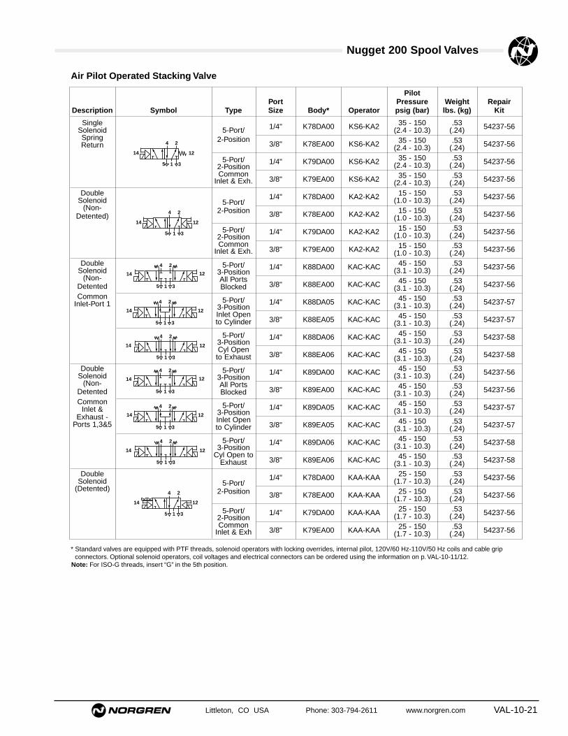
Nugget 200 Spool Valves
Littleton, CO USA Phone: 303-794-2611 www.norgren.com VAL-10-21
Air Pilot Operated Stacking Valve
PilotPort Pressure Weight Repair
Description Symbol Type Size Body* Operator psig (bar) lbs. (kg) Kit
Single 1/4" K78DA00 KS6-KA2 35 - 150 .53 54237-56Solenoid 5-Port/ (2.4 - 10.3) (.24)Spring 2-Position
3/8" K78EA00 KS6-KA2 35 - 150 .53 54237-56Return (2.4 - 10.3) (.24)
5-Port/ 1/4" K79DA00 KS6-KA2 35 - 150 .53 54237-562-Position (2.4 - 10.3) (.24)Common
3/8" K79EA00 KS6-KA2 35 - 150 .53 54237-56Inlet & Exh. (2.4 - 10.3) (.24)Double 1/4" K78DA00 KA2-KA2 15 - 150 .53 54237-56Solenoid 5-Port/ (1.0 - 10.3) (.24)(Non- 2-Position 3/8" K78EA00 KA2-KA2 15 - 150 .53 54237-56Detented) (1.0 - 10.3) (.24)
5-Port/ 1/4" K79DA00 KA2-KA2 15 - 150 .53 54237-562-Position (1.0 - 10.3) (.24)Common
3/8" K79EA00 KA2-KA2 15 - 150 .53 54237-56Inlet & Exh. (1.0 - 10.3) (.24)Double 5-Port/ 1/4" K88DA00 KAC-KAC 45 - 150 .53 54237-56Solenoid 3-Position (3.1 - 10.3) (.24)(Non- All Ports
3/8" K88EA00 KAC-KAC 45 - 150 .53 54237-56Detented Blocked (3.1 - 10.3) (.24)Common 5-Port/ 1/4" K88DA05 KAC-KAC 45 - 150 .53 54237-57Inlet-Port 1 3-Position (3.1 - 10.3) (.24)
Inlet Open3/8" K88EA05 KAC-KAC 45 - 150 .53 54237-57to Cylinder (3.1 - 10.3) (.24)
5-Port/ 1/4" K88DA06 KAC-KAC 45 - 150 .53 54237-583-Position (3.1 - 10.3) (.24)Cyl Open
3/8" K88EA06 KAC-KAC 45 - 150 .53 54237-58to Exhaust (3.1 - 10.3) (.24)Double 5-Port/ 1/4" K89DA00 KAC-KAC 45 - 150 .53 54237-56Solenoid 3-Position (3.1 - 10.3) (.24)(Non- All Ports
3/8" K89EA00 KAC-KAC 45 - 150 .53 54237-56Detented Blocked (3.1 - 10.3) (.24)Common 5-Port/ 1/4" K89DA05 KAC-KAC 45 - 150 .53 54237-57Inlet & 3-Position (3.1 - 10.3) (.24)Exhaust - Inlet Open
3/8" K89EA05 KAC-KAC 45 - 150 .53 54237-57Ports 1,3&5 to Cylinder (3.1 - 10.3) (.24)
5-Port/ 1/4" K89DA06 KAC-KAC 45 - 150 .53 54237-583-Position (3.1 - 10.3) (.24)
Cyl Open to3/8" K89EA06 KAC-KAC 45 - 150 .53 54237-58Exhaust (3.1 - 10.3) (.24)
Double 1/4" K78DA00 KAA-KAA 25 - 150 .53 54237-56Solenoid 5-Port/ (1.7 - 10.3) (.24)(Detented) 2-Position 3/8" K78EA00 KAA-KAA 25 - 150 .53 54237-56(1.7 - 10.3) (.24)
5-Port/ 1/4" K79DA00 KAA-KAA 25 - 150 .53 54237-562-Position (1.7 - 10.3) (.24)Common
3/8" K79EA00 KAA-KAA 25 - 150 .53 54237-56Inlet & Exh (1.7 - 10.3) (.24)
12
24
315
14
24
15 3
14 12
24
15 3
14 12
24
15 3
14 12
24
15 3
14 12
24
15 3
14 12
24
15 3
14 12
24
315
14 12
12
24
315
14
* Standard valves are equipped with PTF threads, solenoid operators with locking overrides, internal pilot, 120V/60 Hz-110V/50 Hz coils and cable gripconnectors. Optional solenoid operators, coil voltages and electrical connectors can be ordered using the information on p. VAL-10-11/12.
Note: For ISO-G threads, insert “G” in the 5th position.

Nugget 200 Spool Valves
VAL-10-22 Littleton, CO USA Phone: 303-794-2611 www.norgren.com
Operator OperatingPressure Weight Repair
Position ISO-G PTF Description psig (bar) lbs. (kg) Kit
2-Position KAB KAA detent, large air 25 .73 54344-16Valves (1.7) (.33)
KA5 KA2 nondetent, large air 15 .70 54344-16(1.0) (.32)
KAF KAE detent bleed - .02 (.5mm) diameter bleed orifice 25 .73 54344-16(1.7) (.33)
KA9 KA8 nondetent bleed - .02 (.5mm) diameter bleed orifice 15 .70 54344-16(1.0) (.32)
KA7 KA6 nondetent, low pressure (inline only) 4 2.46(.27) (1.12) –
KA4 KA1 nondetent, air bias (small air), return for manual operators or as air 25 .33 54344-16bias with KA2 or KA5 (1.7) (.15)
KS5 KS4 nondetent, spring bias, use with KA2 or KA5 35 .44 54344-16(2.5) (.20)
3-Position KAD KAC spring centered 25 .73 54344-16Valves (1.7) (.33)
Air Operators
Air Operators
1.16(29.5)
1.51(38.4)
.59(15.0)
KAA/KAFKA2, KA5KA8, KA9LARGE AIR
1/8-27 PTF orG 1/8 ISO
.52(13.2)
1/8-27 PTF orG 1/8 ISO
KA1, KA4SMALL AIR(AIR BIAS)
.85(21.6)
1/8-27 PTF orG 1/8 ISO(2 Places)
KA6, KA7LOW PRESSURE
4.53(115.0)
1.25(31.8)
1.16(29.5)
2.30(58.4)
KS4, KS5SPRING BIAS
1/8 PTFor
G 1/8 ISO
Air Bleed OperatorsAir bleed operators have a 0.02"(0.5 mm) diameter orifice whichconnects pressure port 1 of themain valve to the operatorpiston and to atmosphere. Asmall amount of air constantlybleeds to atmosphere. The valvespool shifts when air bleed isstopped by a customer-suppliedon-off valve.
KA6 Low PressureOperator(inline valves only)The low pressure operator willshift the valve spool with only 4psig (.28 bar) applied to Port B(Port A open). A minimumvacuum of 6.1" Hg (with HS1spring return) applied to port A(Port B open) will also operatedthe valve. The KA6 operator canalso be used as a differentialpressure operator with orwithout spring return.thedifferential pressure required toshift the valve spool without aspring return is less than 1 psig(2" Hg). A filter/breather shouldbe installed in the open port toreduce the possibility of internalcontamination.
KA1 Air Bias OperatorPiston area of the KA1 operatoris approximately 1/2 of the KA2piston. When pressure isapplied to the KA1 operator thevalve spool shifts to the KA2end. When pressure is appliedto both the KA1 and KA2operators the valve spool shiftsto the KA1 end.
KS4 Spring Bias OperatorPiston area of the KS4 operatoris the same as the KA2operator. The piston is the KS4operator is spring loaded to shiftthe valve spool to the KA2 end.The valve spool shifts to theKS4 end when pressure isapplied to the KA2 operator.When pressure is applied toboth the KS4 and KA2operators the valve spool shiftsto the KA2 end.

Littleton, CO USA Phone: 303-794-2611 www.norgren.com VAL-10-23
● Long lasting spool design
● High flow compact valves
● Wide range of Manual and MechanicalOperators available
● Three functional types available in 3/2, 5/2, and5/3 configurations
1/4", 3/8", or 1/2" Ports, Manual and MechanicalActuated 3/2, 5/2, & 5/3 Inline and Stacking Valves
Technical Data
Medium:Filtered and lubricated or non-lubricated compressed air orvacuum.
Operation:Spool valve air pilot actuated.
Mounting:Stacking – through holes on manifold base.Inline – through holes in valve body.
Port Size:1/4", 3/8", or 1/2" PTF, or 1/4", or 3/8" ISO-G
Operating Pressure:Maximum 150 psig (10.3 bar). For details see overleaf.
Operating Temperature:-20°F to 160°F (-29°C to 71°C)Consult Technical Service for use below 36°F (2°C).
Materials:Body: AluminumSpool: Anodized aluminumElastomers: Nitrile and special nitrile-based low-frictionelastomers.
Ordering InformationTo order standard Nugget 200 manual/mechanical operated valves, quote modelnumber from tables overleaf, e.g. order:
K71DA00-KS1-KK0 for a 5-port/2-position,single Manually Operated black knob, SpringReturn (nondetented) model.
Average Flow Factors in Cv‡ (l/min)Flow Path
Port PortPort 1 to 2 2 to 3
Valve Size 1 to 4 4 to 53-Port, Inline 1/4" 1.6 (1700) 1.7 (1800)
3/8" 1.6 (1700) 1.7 (1800)5-Port, Inline 1/4" 1.6 (1700) 1.7 (1800)
3/8" 1.6 (1700) 1.7 (1800)1/2" 1.6 (1700) 1.7 (1800)
5-Port, Stacking 1/4" 1.8 (1900) 1.4 (1450)3/8" 1.8 (1900) 1.4 (1450)
‡ Flow Rating determined in accordance withNFPA/T3.21.3, Pneumatic fluid power – Flow testprocedure and reporting method – For fixed orificecomponents.

Nugget 200 Spool Valves
VAL-10-24 Littleton, CO USA Phone: 303-794-2611 www.norgren.com
Min.Operating
Position Operator Description Force lbs. (kg)
2-Position KP0 Tappet, Nondetent 18.0(8.2)
KR2 Lever Roller, Nondetent (Inline Only) 11.0(5.0)
KR3 One-Way Trip Roller, Nondetent 11.0(5.0)
KR4 Lever Roller, Nondetent 11.0(5.0)
KR5 One-Way Trip Roller, Nondetent (Inline Only) 11.0(5.0)
Mechanical Operators
Min.Operating
Position Operator Description Force lbs. (kg)
2-Position KB0 Palm Button - Black, Nondetent (Inline Only) 18.0(8.2)
KB1 Palm Button - Red, Nondetent (Inline Only) 18.0(8.2)
KB2 Palm Button - Green, Nondetent (Inline Only) 18.0(8.2)
KB3 Palm Button - Black, Detent (Inline Only) 9.0(4.1)
KB4 Palm Button - Red, Detent (Inline Only) 9.0(4.1)
KB5 Palm Button - Green, Detent (Inline Only) 9.0(4.1)
KF0 Foot Pedal, Nondetent 11.0(5.0)
KK0 Knob - Black, Nondetent 18.0(8.2)
KK1 Knob - Black, Detent 9.0(4.1)
KL0 Lever, Nondetent (Inline Only) 9.0(4.1)
KL1 Lever, 2-Position Detent (Inline Only) 7.0(3.2)
KL5 Lever, Nondetent 9.0(4.1)
KL6 Lever, 2-Position Detent 7.0(3.2)
KT0 Treadle, Nondetent (Inline Only) 13.0(5.9)
KT1 Treadle, 2-Position Detent (Inline Only) 9.0(4.1)
3-Position KB6 Palm Button - Black, Spring Centered 9.0(4.1)
KK2 Knob - Black, Spring Centered 9.0(4.1)
KK3 Knob - black, 3-Position Detent 9.0(4.1)
KL2 Lever, Spring Centered (Inline Only) 7.0(3.2)
KL3 Lever, 3-Position Detent (Inline Only) 7.0(3.2)
KL7 Lever, Spring Centered 7.0(3.2)
KL8 Lever, 3-Position Detent 7.0(3.2)
KT2 Treadle, Spring Centered 9.0(4.1)
Manual Operators

Nugget 200 Spool Valves
Littleton, CO USA Phone: 303-794-2611 www.norgren.com VAL-10-25
Manually Operated Inline Valves - Palm Button
MiniaturePort Operating Weight Repair
Description Symbol Type Size Body* Operator Force lbs. (kg) lbs. (kg) Kits
Spring 1/4" K41DA00 KS1-KB0 18.0 2.22 54237-59Return 3-Port/ (8.2) (1.01)(Non- 2-Position
3/8" K41EA00 KS1-KB0 18.0 2.22 54237-59Detented (8.2) (1.01)
1/4" K71DA00 KS1-KB0 18.0 2.22 54237-56(8.2) (1.01)5-Port/ 3/8" K71EA00 KS1-KB0 18.0 2.22 54237-562-Position (8.2) (1.01)
1/2" K71FA00 KS1-KB0 18.0 2.22 54237-56(8.2) (1.01)End Cap 1/4" K41DA00 KC0-KB0 18.0 2.22 54237-59(Non- 3-Port/ (8.2) (1.01)Detented) 2-Position
3/8" K41EA00 KC0-KB0 18.0 2.22 54237-59(8.2) (1.01)
1/4" K71DA00 KC0-KB0 18.0 2.22 54237-56(8.2) (1.01)5-Port/ 3/8" K71EA00 KC0-KB0 18.0 2.22 54237-562-Position (8.2) (1.01)
1/2" K71FA00 KC0-KB0 18.0 2.22 54237-56(8.2) (1.01)End Cap 1/4" K41DA00 KC0-KB3 9.0 2.22 54237-59(Detented) 3-Port/ (4.1) (1.01)
2-Position 3/8" K41EA00 KC0-KB3 9.0 2.22 54237-59(4.1) (1.01)
1/4" K71DA00 KC0-KB3 9.0 2.22 54237-56(4.1) (1.01)5-Port/ 3/8" K71EA00 KC0-KB3 9.0 2.22 54237-562-Position (4.1) (1.01)
1/2" K71FA00 KC0-KB3 9.0 2.22 54237-56(4.1) (1.01)End Cap 1/4" K81DA00 KC0-KB6 9.0 4.40 54237-56(Spring 5-Port/ (4.1) (2.00)Centered) 3-Position 3/8" K81EA00 KC0-KB6 9.0 4.40 54237-56All Ports (4.1) (2.00)
Blocked1/2" K81FA00 KC0-KB6 9.0 4.40 54237-56(4.1) (2.00)
1/4" K81DA05 KC0-KB6 9.0 4.40 54237-575-Port/ (4.1) (2.00)
3-Position3/8" K81EA05 KC0-KB6 9.0 4.40 54237-57Inlet Open (4.1) (2.00)
to Cylinder1/2" K81FA05 KC0-KB6 9.0 4.40 54237-57(4.1) (2.00)
1/4" K81DA06 KC0-KB6 9.0 2.00 54237-585-Port/ (4.1) (4.40)
3-Position 3/8" K81EA06 KC0-KB6 9.0 4.40 54237-58Cyl Open (4.1) (2.00)to Exhaust
1/2" K81FA06 KC0-KB6 9.0 4.40 54237-58(4.1) (2.00)
10
2
13
24
315
24
315
2
13
24
315
24
15 3
24
15 3
24
15 3
2
13
* Standard valves are equipped with PTF threads, solenoid operators with locking overrides, internal pilot, 120V/60 Hz-110V/50 Hz coils and cable grip connectors.Optional solenoid operators, coil voltages and electrical connectors can be ordered using the information on p. VAL-10-11/12.
Note: For ISO-G threads, insert “G” in the 5th position. 1/2" ported bodies are not available with ISO G threads.

Nugget 200 Spool Valves
VAL-10-26 Littleton, CO USA Phone: 303-794-2611 www.norgren.com
Manually Operated Inline Valves - Knob
PilotPort Pressure Weight Repair
Description Symbol Type Size Body* Operator psig (bar) lbs. (kg) Kit
Spring 1/4" K41DA00 KS1-KK0 18.0 2.22 54237-59Return 3-Port/ (8.2) (1.01)(Non- 2-Position
3/8" K41EA00 KS1-KK0 18.0 2.22 54237-59Detented (8.2) (1.01)
1/4" K71DA00 KS1-KK0 18.0 2.22 54237-56(8.2) (1.01)5-Port/ 3/8" K71EA00 KS1-KK0 18.0 2.22 54237-562-Position (8.2) (1.01)
1/2" K71FA00 KS1-KK0 18.0 2.22 54237-56(8.2) (1.01)End Cap 1/4" K41DA00 KC0-KK0 18.0 2.22 54237-59(Non- 3-Port/ (8.2) (1.01)Detented) 2-Position
3/8" K41EA00 KC0-KK0 18.0 2.22 54237-59(8.2) (1.01)
1/4" K71DA00 KC0-KK0 18.0 2.22 54237-56(8.2) (1.01)5-Port/ 3/8" K71EA00 KC0-KK0 18.0 2.22 54237-562-Position (8.2) (1.01)
1/2" K71FA00 KC0-KK0 18.0 2.22 54237-56(8.2) (1.01)End Cap 1/4" K41DA00 KC0-KK1 9.0 2.22 54237-59(Detented) 3-Port/ (4.1) (1.01)
2-Position 3/8" K41EA00 KC0-KK1 9.0 2.22 54237-59(4.1) (1.01)
1/4" K71DA00 KC0-KK1 9.0 2.22 54237-56(4.1) (1.01)5-Port/ 3/8" K71EA00 KC0-KK1 9.0 2.22 54237-562-Position (4.1) (1.01)
1/2" K71FA00 KC0-KK1 9.0 2.22 54237-56(4.1) (1.01)
1/4" K81DA00 KC0-KK3 9.0 4.40 54237-565-Port/ (4.1) (2.00)
3-Position 3/8" K81EA00 KC0-KK3 9.0 4.40 54237-56All Ports (4.1) (2.00)Blocked
1/2" K81FA00 KC0-KK3 9.0 4.40 54237-56(4.1) (2.00)
1/4" K81DA05 KC0-KK3 9.0 4.40 54237-575-Port/ (4.1) (2.00)
3-Position3/8" K81EA05 KC0-KK3 9.0 4.40 54237-57Inlet Open (4.1) (2.00)
to Cylinder1/2" K81FA05 KC0-KK3 9.0 4.40 54237-57(4.1) (2.00)
1/4" K81DA06 KC0-KK3 9.0 4.40 54237-585-Port/ (4.1) (2.00)
3-Position3/8" K81EA06 KC0-KK3 9.0 4.40 54237-58Cyl Open (4.1) (2.00)
to Exhaust1/2" K81FA06 KC0-KK3 9.0 4.40 54237-58(4.1) (2.00)
End Cap 1/4" K81DA00 KC0-KK2 9.0 4.40 54237-56(Spring 5-Port/ (4.1) (2.00)Centered) 3-Position 3/8" K81EA00 KC0-KK2 9.0 4.40 54237-56All Ports (4.1) (2.00)
Blocked1/2" K81FA00 KC0-KK2 9.0 4.40 54237-56(4.1) (2.00)
1/4" K81DA05 KC0-KK2 9.0 4.40 54237-575-Port/ (4.1) (2.00)
3-Position3/8" K81EA05 KC0-KK2 9.0 4.40 54237-57Inlet Open (4.1) (2.00)
to Cylinder1/2" K81FA05 KC0-KK2 9.0 4.40 54237-57(4.1) (2.00)
1/4" K81DA06 KC0-KK2 9.0 4.40 54237-585-Port/ (4.1) (2.00)
3-Position 3/8" K81EA06 KC0-KK2 9.0 4.40 54237-58Cyl Open (4.1) (2.00)to Exhaust
1/2" K81FA06 KC0-KK2 9.0 4.40 54237-58(4.1) (2.00)
10
2
13
24
315
24
315
2
13
24
315
24
15 3
24
15 3
24
15 3
24
15 3
24
15 3
24
15 3
2
13
* Standard valves are equipped with PTF threads, solenoid operators with locking overrides, internal pilot, 120V/60 Hz-110V/50 Hz coils and cable grip connectors.Optional solenoid operators, coil voltages and electrical connectors can be ordered using the information on p. VAL-10-11/12.
Note: For ISO-G threads, insert “G” in the 5th position. 1/2" ported bodies are not available with ISO G threads.
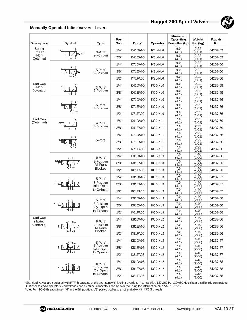
Nugget 200 Spool Valves
Littleton, CO USA Phone: 303-794-2611 www.norgren.com VAL-10-27
Manually Operated Inline Valves - Lever
MinimumPort Operating Weight Repair
Description Symbol Type Size Body* Operator Force lbs. (kg) lbs. (kg) Kit
Spring 1/4" K41DA00 KS1-KL0 9.0 2.22 54237-59Return 3-Port/ (4.1) (1.01)(Non- 2-Position
3/8" K41EA00 KS1-KL0 9.0 2.22 54237-59Detented (4.1) (1.01)
1/4" K71DA00 KS1-KL0 9.0 2.22 54237-56(4.1) (1.01)5-Port/ 3/8" K71EA00 KS1-KL0 9.0 2.22 54237-562-Position (4.1) (1.01)
1/2" K71FA00 KS1-KL0 9.0 2.22 54237-56(4.1) (1.01)End Cap 1/4" K41DA00 KC0-KL0 9.0 2.22 54237-59(Non- 3-Port/ (4.1) (1.01)Detented) 2-Position
3/8" K41EA00 KC0-KL0 9.0 2.22 54237-59(4.1) (1.01)
1/4" K71DA00 KC0-KL0 9.0 2.22 54237-56(4.1) (1.01)5-Port/ 3/8" K71EA00 KC0-KL0 9.0 2.22 54237-562-Position (4.1) (1.01)
1/2" K71FA00 KC0-KL0 9.0 2.22 54237-56(4.1) (1.01)End Cap 1/4" K41DA00 KC0-KL1 7.0 2.22 54237-59(Detented) 3-Port/ (4.1) (1.01)
2-Position 3/8" K41EA00 KC0-KL1 7.0 2.22 54237-59(4.1) (1.01)
1/4" K71DA00 KC0-KL1 7.0 2.22 54237-56(4.1) (1.01)5-Port/ 3/8" K71EA00 KC0-KL1 7.0 2.22 54237-56(4.1) (1.01)
1/2" K71FA00 KC0-KL1 7.0 2.22 54237-56(4.1) (1.01)
1/4" K81DA00 KC0-KL3 7.0 4.40 54237-565-Port/ (4.1) (2.00)3-Position 3/8" K81EA00 KC0-KL3 7.0 4.40 54237-56All Ports (4.1) (2.00)Blocked 1/2" K81FA00 KC0-KL3 7.0 4.40 54237-56(4.1) (2.00)
1/4" K81DA05 KC0-KL3 7.0 4.40 54237-575-Port/ (4.1) (2.00)3-Position 3/8" K81EA05 KC0-KL3 7.0 4.40 54237-57Inlet Open (4.1) (2.00)to Cylinder 1/2" K81FA05 KC0-KL3 7.0 4.40 54237-57(4.1) (2.00)
1/4" K81DA06 KC0-KL3 7.0 4.40 54237-585-Port/ (4.1) (2.00)3-Position 3/8" K81EA06 KC0-KL3 7.0 4.40 54237-58Cyl Open (4.1) (2.00)to Exhaust 1/2" K81FA06 KC0-KL3 7.0 4.40 54237-58(4.1) (2.00)
End Cap 1/4" K81DA00 KC0-KL2 7.0 4.40 54237-56(Spring 5-Port/ (4.1) (2.00)
Centered) 3-Position 3/8" K81EA00 KC0-KL2 7.0 4.40 54237-56All Ports (4.1) (2.00)Blocked
1/2" K81FA00 KC0-KL2 7.0 4.40 54237-56(4.1) (2.00)
1/4" K81DA05 KC0-KL2 7.0 4.40 54237-575-Port/ (4.1) (2.00)
3-Position3/8" K81EA05 KC0-KL2 7.0 4.40 54237-57Inlet Open (4.1) (2.00)
to Cylinder1/2" K81FA05 KC0-KL2 7.0 4.40 54237-57(4.1) (2.00)
1/4" K81DA06 KC0-KL2 7.0 4.40 54237-585-Port/ (4.1) (2.00)
3-Position 3/8" K81EA06 KC0-KL2 7.0 4.40 54237-58Cyl Open (4.1) (2.00)to Exhaust
1/2" K81FA06 KC0-KL2 7.0 4.40 54237-58(4.1) (2.00)
10
2
13
24
315
24
315
2
13
24
315
24
15 3
24
15 3
24
15 3
24
15 3
24
15 3
24
15 3
2
13
* Standard valves are equipped with PTF threads, solenoid operators with locking overrides, internal pilot, 120V/60 Hz-110V/50 Hz coils and cable grip connectors.Optional solenoid operators, coil voltages and electrical connectors can be ordered using the information on p. VAL-10-11/12.
Note: For ISO-G threads, insert “G” in the 5th position. 1/2" ported bodies are not available with ISO G threads.
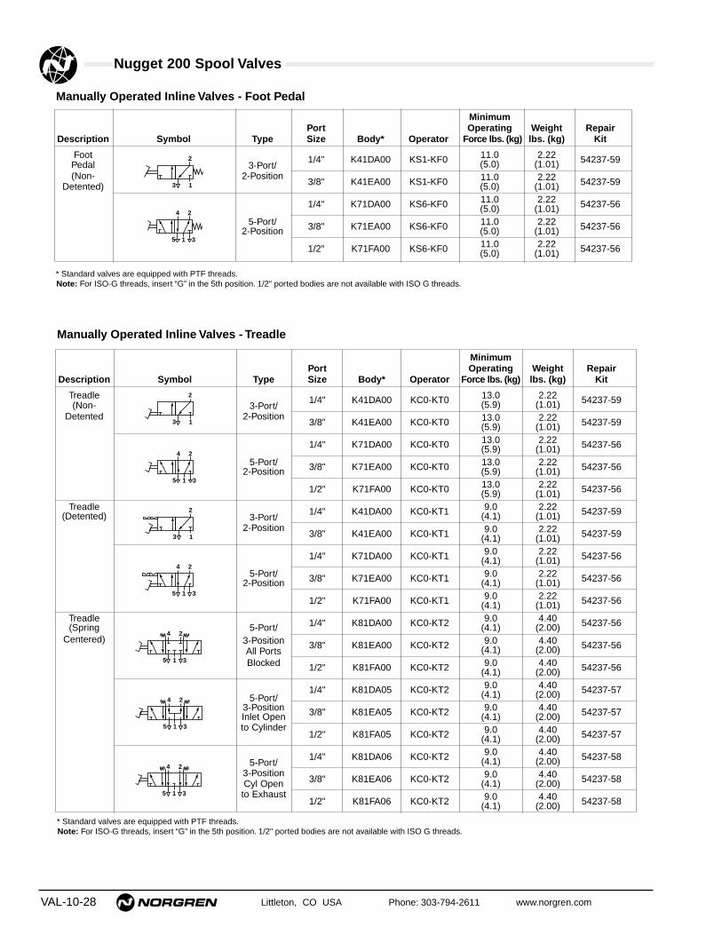
Nugget 200 Spool Valves
VAL-10-28 Littleton, CO USA Phone: 303-794-2611 www.norgren.com
Manually Operated Inline Valves - Foot Pedal
MinimumPort Operating Weight Repair
Description Symbol Type Size Body* Operator Force lbs. (kg) lbs. (kg) Kit
Foot 1/4" K41DA00 KS1-KF0 11.0 2.22 54237-59Pedal 3-Port/ (5.0) (1.01)(Non- 2-Position
3/8" K41EA00 KS1-KF0 11.0 2.22 54237-59Detented) (5.0) (1.01)
1/4" K71DA00 KS6-KF0 11.0 2.22 54237-56(5.0) (1.01)5-Port/ 3/8" K71EA00 KS6-KF0 11.0 2.22 54237-562-Position (5.0) (1.01)
1/2" K71FA00 KS6-KF0 11.0 2.22 54237-56(5.0) (1.01)
2
13
24
315
* Standard valves are equipped with PTF threads.Note: For ISO-G threads, insert “G” in the 5th position. 1/2" ported bodies are not available with ISO G threads.
Manually Operated Inline Valves - Treadle
MinimumPort Operating Weight Repair
Description Symbol Type Size Body* Operator Force lbs. (kg) lbs. (kg) Kit
Treadle 1/4" K41DA00 KC0-KT0 13.0 2.22 54237-59(Non- 3-Port/ (5.9) (1.01)Detented 2-Position
3/8" K41EA00 KC0-KT0 13.0 2.22 54237-59(5.9) (1.01)
1/4" K71DA00 KC0-KT0 13.0 2.22 54237-56(5.9) (1.01)5-Port/ 3/8" K71EA00 KC0-KT0 13.0 2.22 54237-562-Position (5.9) (1.01)
1/2" K71FA00 KC0-KT0 13.0 2.22 54237-56(5.9) (1.01)Treadle 1/4" K41DA00 KC0-KT1 9.0 2.22 54237-59(Detented) 3-Port/ (4.1) (1.01)
2-Position3/8" K41EA00 KC0-KT1 9.0 2.22 54237-59(4.1) (1.01)
1/4" K71DA00 KC0-KT1 9.0 2.22 54237-56(4.1) (1.01)5-Port/ 3/8" K71EA00 KC0-KT1 9.0 2.22 54237-562-Position (4.1) (1.01)
1/2" K71FA00 KC0-KT1 9.0 2.22 54237-56(4.1) (1.01)Treadle 1/4" K81DA00 KC0-KT2 9.0 4.40 54237-56(Spring 5-Port/ (4.1) (2.00)
Centered) 3-Position 3/8" K81EA00 KC0-KT2 9.0 4.40 54237-56All Ports (4.1) (2.00)Blocked 1/2" K81FA00 KC0-KT2 9.0 4.40 54237-56(4.1) (2.00)
1/4" K81DA05 KC0-KT2 9.0 4.40 54237-575-Port/ (4.1) (2.00)
3-Position 3/8" K81EA05 KC0-KT2 9.0 4.40 54237-57Inlet Open (4.1) (2.00)to Cylinder
1/2" K81FA05 KC0-KT2 9.0 4.40 54237-57(4.1) (2.00)
1/4" K81DA06 KC0-KT2 9.0 4.40 54237-585-Port/ (4.1) (2.00)
3-Position3/8" K81EA06 KC0-KT2 9.0 4.40 54237-58Cyl Open (4.1) (2.00)
to Exhaust1/2" K81FA06 KC0-KT2 9.0 4.40 54237-58(4.1) (2.00)
2
13
24
315
24
315
24
15 3
24
15 3
24
15 3
2
13
* Standard valves are equipped with PTF threads.Note: For ISO-G threads, insert “G” in the 5th position. 1/2" ported bodies are not available with ISO G threads.
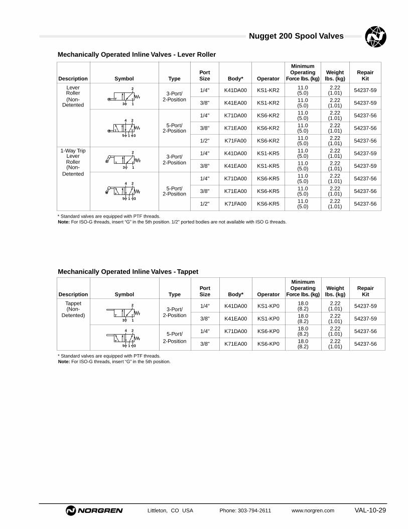
Nugget 200 Spool Valves
Littleton, CO USA Phone: 303-794-2611 www.norgren.com VAL-10-29
Mechanically Operated Inline Valves - TappetMinimum
Port Operating Weight RepairDescription Symbol Type Size Body* Operator Force lbs. (kg) lbs. (kg) Kit
Tappet 1/4" K41DA00 KS1-KP0 18.0 2.22 54237-59(Non- 3-Port/ (8.2) (1.01)Detented) 2-Position
3/8" K41EA00 KS1-KP0 18.0 2.22 54237-59(8.2) (1.01)
1/4" K71DA00 KS6-KP0 18.0 2.22 54237-565-Port/ (8.2) (1.01)2-Position 3/8" K71EA00 KS6-KP0 18.0 2.22 54237-56(8.2) (1.01)
2
13
24
315
* Standard valves are equipped with PTF threads.Note: For ISO-G threads, insert “G” in the 5th position.
Mechanically Operated Inline Valves - Lever Roller
MinimumPort Operating Weight Repair
Description Symbol Type Size Body* Operator Force lbs. (kg) lbs. (kg) Kit
Lever 1/4" K41DA00 KS1-KR2 11.0 2.22 54237-59Roller 3-Port/ (5.0) (1.01)(Non- 2-Position
3/8" K41EA00 KS1-KR2 11.0 2.22 54237-59Detented (5.0) (1.01)
1/4" K71DA00 KS6-KR2 11.0 2.22 54237-56(5.0) (1.01)5-Port/ 3/8" K71EA00 KS6-KR2 11.0 2.22 54237-562-Position (5.0) (1.01)
1/2" K71FA00 KS6-KR2 11.0 2.22 54237-56(5.0) (1.01)1-Way Trip 1/4" K41DA00 KS1-KR5 11.0 2.22 54237-59Lever 3-Port/ (5.0) (1.01)
Roller 2-Position3/8" K41EA00 KS1-KR5 11.0 2.22 54237-59(Non- (5.0) (1.01)
Detented1/4" K71DA00 KS6-KR5 11.0 2.22 54237-56(5.0) (1.01)
5-Port/ 3/8" K71EA00 KS6-KR5 11.0 2.22 54237-562-Position (5.0) (1.01)
1/2" K71FA00 KS6-KR5 11.0 2.22 54237-56(5.0) (1.01)
2
13
24
315
24
315
2
13
* Standard valves are equipped with PTF threads.Note: For ISO-G threads, insert “G” in the 5th position. 1/2" ported bodies are not available with ISO G threads.
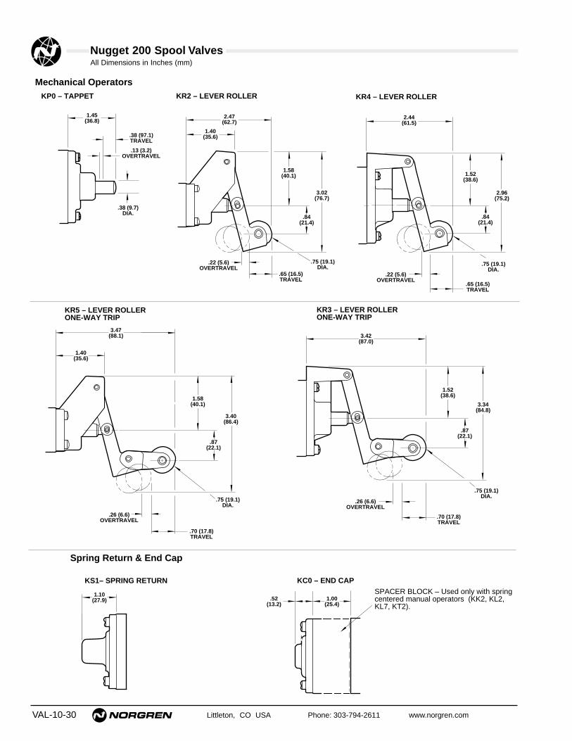
Nugget 200 Spool ValvesAll Dimensions in Inches (mm)
VAL-10-30 Littleton, CO USA Phone: 303-794-2611 www.norgren.com
Mechanical Operators
Spring Return & End Cap
.38 (9.7)DIA.
1.45(36.8)
.38 (97.1)TRAVEL
.13 (3.2)OVERTRAVEL
KP0 – TAPPET
3.40(86.4)
1.58(40.1)
.87(22.1)
.75 (19.1)DIA.
.70 (17.8)TRAVEL
.26 (6.6)OVERTRAVEL
1.40(35.6)
3.47(88.1)
KR5 – LEVER ROLLERONE-WAY TRIP
1.10(27.9)
KS1– SPRING RETURN
1.00(25.4)
KC0 – END CAP
.52(13.2)
SPACER BLOCK – Used only with springcentered manual operators (KK2, KL2, KL7, KT2).
3.34(84.8)
1.52(38.6)
.87(22.1)
.75 (19.1)DIA.
.70 (17.8)TRAVEL
.26 (6.6)OVERTRAVEL
3.42(87.0)
KR3 – LEVER ROLLERONE-WAY TRIP
KR2 – LEVER ROLLER
3.02(76.7)
2.47(62.7)
1.40(35.6)
1.58(40.1)
.84(21.4)
.75 (19.1)DIA.
.65 (16.5)TRAVEL
.22 (5.6)OVERTRAVEL
KR4 – LEVER ROLLER
2.96(75.2)
2.44(61.5)
1.52(38.6)
.84(21.4)
.75 (19.1)DIA.
.65 (16.5)TRAVEL
.22 (5.6)OVERTRAVEL

Nugget 200 Spool ValvesAll Dimensions in Inches (mm)
Littleton, CO USA Phone: 303-794-2611 www.norgren.com VAL-10-31
Manual Operators
.38 (9.7)TRAVEL
3.34(84.8)
KB0/KB5 – PALM BUTTON
1.38(35.1)
2.30(58.4)
KB3/KB5
KB0/KB2
M20 x 1.5 – 6gPnl Mtg Hole – .81 (20.6)Max Pnl Thk – .25 (6.4)
.38 (9.7)TRAVELKK0, KK1
3.15(80.0)
KK0/KK3 – KNOB
1.00(25.4)
2.19(55.6)
KK1
KK0
.19 (4.8) TRAVEL
.19 (4.8) KK2, KK3
KK2, KK32.99(75.9)
Travel (2-position) KL0, KL1
1.35(34)
KL0/KL3 – LEVER
1.79(45)
.90(23)
.90(23) Travel (3-position)
KL2, KL3
2.5(64)
3.5(89)
KL0
KL1/KL3
3.90(99)
1.00(25)Dia.
Travel (2-position) KL5, KL6
.85(22)
KL5/KL8 – LEVER
.80(20)
.40(10)
.40(10)
Travel (3-position) KL7, KL8
3.07(78)
2.07(53) KL5
KL6/KL8
3.98(101)
1.00(25)Dia.
KT0/KT2 – TREADLE
4.28(108.7)
5.28(134.1)
KT0
KT1/KT2
2.81(71.4)
1.18 (30.0)TRAVEL
7.42(188.5) KF0 – FOOT PEDAL
1.58(40.1)
.56 (14.2)TRAVEL
5.04(128.0)

VAL-10-32 Littleton, CO USA Phone: 303-794-2611 www.norgren.com
Nugget 200 Spool Valves
• Reduces plumbing and installation time.
• Lightweight aluminum construction.
• 3/4" PTF common inlet and exhaust ports.
• For use with most Nugget 200 1/4" and 3/8"inline valves.
• Available in 2 to 10 station lengths.
Fixed Length Manifold for 1/4" and 3/8" Inline Valves
Technical DataFluid: Compressed airMaximum Pressure: See valve specificationsOperating Pressure: See valve specificationsPort Size: 3/4" PTF Inlet and ExhaustMounting Holes: 0.28" (7 mm) DiameterMaterials:
Manifold – AluminumSeals – Nitrile
Ordering ExampleTo order valves mounted to a fixed length manifold pleasefollow these steps:1.Order only 1/4" and 3/8" inline bodies ending in 2
(i.e. K71DA02)*2.Note the manifold is to be assembled.3.Note positions of various valving.
Example:One four station Nugget 200 fixed length manifoldassembly consisting of:Position 1:
(1) K71DA02 - KY6 - KY6 (Dbl Sol Valve)Positions 2 - 4:
(3) K71DA02 - KS6 - KY6 (Single Solenoid Valve)(1) 13249-62 (Four Station Manifold)(4) 99-051-530 (Assembly Charge)
* Note standard K71DA00 and K71EA00 bodies cannot bemounted to fixed length manifold.
Blanking Plate Kit: 54588-50

Nugget 200 Spool ValvesAll Dimensions in Inches (mm)
Littleton, CO USA Phone: 303-794-2611 www.norgren.com VAL-10-33
Ordering Information - Models listedinclude all mounting hardware andgaskets. Inlet and exhaust ports are3/4" PTF.
Number of Stations Part Number2 13249-603 13249-614 13249-625 13249-636 13249-648 13249-6510 13249-66
Item Number Part Required Number
Mounting Screws 2 6005-14Seals 3 2338-25
1 35
1 35
'L'
1.39 (35.3) 1.50 (38.1)ø .28 (7.1) Thru 4 Plcs
1.13
(2.8
7).2
5 (6
.4)
1.48 (37.6)
2.14 (54.4)
4.28 (108.7)
1.48 (37.6)
1.78
(45
.2)
.65
(16.
5)2
Pla
ces
M5 x 0.8 - 6G(typ 2 places per station)
Dash "L"-60 4.000 (101.6)-61 5.750 (146.0)-62 7.375 (187.3)-63 9.125 (231.8)-64 10.750 (273.0)-65 14.125 (358.8)-66 17.375 (441.3)
Repair Parts
Fixed Length Manifold

Nugget 200 Spool Valves
VAL-10-34 Littleton, CO USA Phone: 303-794-2611 www.norgren.com
Important:1.Solenoid operated 2-position detent and
nondetent, and 3-position spring centeredvalves can be combined in the same stack.
2.Plain stacking valves with common port 1only and plain valves with common ports 1, 3and 5 can be combined in one stack ifgrouped together at opposite ends.
3.A stack or group of valves with common port1 only must have isolating plugs installed inthe manifolding exhaust ports (3 and 5)between each valve and each of the endplates. Two exhaust port isolating plugs arefurnished with each valve. Installation neednot be specified on orders for factoryassembled stacks as this will be doneautomatically.
4.Isolating plugs furnished in the end plate kitat no extra cost can be placed between twostacking valves to block the common portsand separate a section of the valve stack toaccommodate two different input pressures.One pressure is brought in from the front endplate and the second pressure from the endplate in the back. (Specify on order formunder “Special Instructions” where to installisolating plugs.)
5.Ports 1, 3 and 5 in one end plate can beplugged if so specified on order under“Special Instructions”.
Special Instructions – Factory Assembled Stacking ValvesFor Ordering purposes the valve stack is oriented as shown incolumn two:Unless otherwise noted:1.Cylinder (outlet) ports are oriented toward the bottom
2.The 1 2 operator is on the left side, the 1 4 operator on the right side.
3.Valves are listed from the FRONT to the BACK
Example 1: One stacking valve assembly with common inlet andexhaust (ports 1, 3 and 5) and junction boxes withsolenoid operators with indicator lights. Isolating plugsfor two different working pressures installed betweenvalves 4 and 5.
Example 2: One Combination stacking valve assembly withoutjunction boxes. Valves on one end of stack withcommon inlet and exhaust (ports 1, 3 and 5), and onthe opposite end with common inlet only (port 1).
Answer Example 1
Answer Example 2
Note:Mufflers or filter nuts should be used in all valve body, end plate, orsolenoid operator exhaust ports to prevent entry of dirt and toreduce the noise level of the exhausting air.In wet locations, exhaust ports should not face upward to lessenthe possibility of liquids entering the unit.
Valve Special Pos. No. Quantity Product Number Instructions
1 1 K79DA50-KS6-KM12 1 K79DA50-KS6-KM13 1 K79DA50-KM6-KM64 1 K89EA50-KM8-KM8
Isolating PlugsCommon
Ports 1, 3 & 55 1 K79DA50-KM6-KM66 1 K79DA50-KM6-KM67 1 K79DA50-KM6-KM6
1 13295-50 End Plate Kit
Valve Special Pos. No. Quantity Product Number Instructions
1 1 K79DA00-KS6-KV22 1 K89EA00-KV0-KV03 1 K79EA00-KV2-KV24 1 K78DA00-KS6-KV25 1 K78EA00-KS6-KV2
1 13295-52 End Plate Kit
PORT 3COMMONEXHAUST
VALVE 1
VALVE 2
VALVE 3
FRONT 1 4 END
BACK
CommonExhaust
1 2 END
PORT 1COMMONINLET
PORT 2CYLINDERPORT PORT 4
CYLINDERPORT
PORT 5
Factory Assembled Stacking Valve Common Inlet & Exhaust

Nugget 200 Spool Valves
Littleton, CO USA Phone: 303-794-2611 www.norgren.com VAL-10-35
Special Instructions – Stacking Valves● The numbers shown in the stacking valve Ordering Information
tables include the valve plus the interface seals and threaded tierods needed to connect the valve to the adjacent valve or endplate.
● An end plate kit is required to complete a valve stack assembly.It includes two end plates and the necessary seals and attachinghardware. Also included are three pipe plugs to close one end ofthe stack and three isolating plugs (discs). The isolating plugscan be used to separate the valve stack into two sections andthus allow valves with a common inlet only to be combined withvalves having both a common inlet and common exhausts, or toallow the use of different inlet pressures.
● Always specify the valve order number, the end plate kit numberand the quantity desired. See table below.
● Valves and end plates are shipped unassembled. See pp.VAL-10-36/37 for factory assembled stacks.
● Stacking valves are available in two configurations – CommonInlet and Exhaust (Ports 1, 3, and 5) and Common Inlet Only(Port 1). Speed controls can be installed in the exhaust portsonly on the Common Inlet (Port 1) configuration. The CommonInlet (Port 1) configuration cannot be used with the junction box.
● Solenoid operated 2-position detent and nondetent, and 3-position spring centered valves can be combined in the samestack.
Isolating Plugs
O-Ring
PipePlug End Plate
End Plate
Tie Rod
Isolating Plugs
O-Rings
End Plate
End Plate
Tie Rod
Typical Valve Stack (Common Inlet Only - Port1)
Typical Valve Stack (Common Inlet and Exhaust - Ports 1, 3 and 5)
Order Number3/8 PTF G 3/8 ISO
End Plate Kit Ports PortsFor valves without
junction box 13295-52 13295-53
For valves with junction box 13295-50 13295-51
QuantityIsolating Plugs Required Order No.
Inlet (Port 1) 1 54350-89
Exhaust (Ports 3 & 5) 2 54350-88
Isolating PlugsStacked banks of valves can be divided intotwo sections by substituting the isolating plugsfor the O-rings between any two valves. Theycan also be used to block the end plate portson one end if desired. Although one inlet portand two exhaust port isolating plugs areincluded with the end plate kit, the individualplugs can be ordered separately.

Nugget 200 Spool Valves
VAL-10-36 Littleton, CO USA Phone: 303-794-2611 www.norgren.com
OPERATORS FOR 2-POSITION INLINE AND STACKING BODIES
Pilot PortPTF ISOAir Operators
KAA KAB Detent, Large AirKA2 KA5 Nondetent, Large AirKAE KAF Detent Bleed – .02 (.5 mm) Diameter
Bleed Orifice
Standard Solenoid Operator with RotatableCable Grip Connector & Locking Override
KV2 KVC Nondetent, Internal PilotKV5 KVF Nondetent, External PilotKVL KVN Detent, Internal Pilot
Standard Solenoid Operator without ElectricalConnector, with Locking Override
K1L K1N Detent, Internal Pilot
Standard Solenoid Operator with Rotatable 1/2"Conduit Connector & Locking Override
K32 K3C Nondetent, Internal PilotK35 K3F Nondetent, External PilotK3L K3N Detent, Internal PilotK3M K3P Detent, External Pilot
Standard Solenoid Operator with Molded CordConnector, 5 Foot/3-Conductor Cable & LockingOverride
K52 K5C Nondetent, Internal PilotK55 K5F Nondetent, External PilotK5L K5N Detent, Internal Pilot
CSA Listed Solenoid Operator with Fixed 1/2"Conduit Connector & Locking Override
KD2 KDC Nondetent, Internal Pilot
CSA Listed Solenoid Operator without ElectricalConnector, with Locking Override
KQ2 KQC Nondetent, Internal Pilot
Hazardous Location Solenoid Operator — Inline Valves Only with Locking Override
KX2 KXC Nondetent, Internal Pilot
Manual Operators
KB0 Palm Button – Black, Nondetent (Inline Only)KB1 Palm Button – Red, Nondetent (Inline Only)KB2 Palm Button – Green, Nondetent
(Inline Only)KB3 Palm Button – Black, Detent (Inline Only)KB4 Palm Button – Red, Detent (Inline Only)KB5 Palm Button – Green, Detent (Inline Only)KF0 Foot Pedal, NondetentKK0 Knob – Black, NondetentKK1 Knob – Black, DetentKL0 Lever, Nondetent (Inline Only)KL1 Lever, 2-Position Detent (Inline Only)KL5 Lever, NondetentKL6 Lever, 2-Position DetentKT0 Treadle, Nondetent (Inline Only)KT1 Treadle, 2-Position Detent (Inline Only)
Mechanical Operators
KP0 Tappet, NondetentKR2 Lever Roller, Nondetent (Inline Only)KR3 One-Way Trip Roller, NondetentKR4 Lever Roller, NondetentKR5 One-Way Trip Roller, Nondetent
(Inline Only)
STACKING BODIES WITHOUT JUNCTION BOX –COMMON PRESSURE PORT 1 ONLY (USEWHEN SPEED CONTROLS ARE NEEDED IN EXHAUST PORTS 3 & 5)K78 – 4-Way, 2-Position, 5-PortK88 – 4-Way, 3-Position, 5-Port
STACKING BODIES – COMMON PRESSURE PORT 1 AND COMMON EXHAUST PORTS 3 & 5K79 – 4-Way, 2-Position, 5-PortK89 – 4-Way, 3-Position, 5-Port
K 4 1 D A 0 0 – K S 1 – K V 2Valve Body
1 0 End1 2 EndOperator
1 2 End1 4 EndOperator
3-Way Valves4-Way Valves
Nugget 200 Product Numbering System — Air, Manual, andMechanical Operators and Solenoid Operators with Locking Override
OPERATORS FOR 3-POSITION INLINE AND STACKING BODIES
Pilot PortPTF ISOAir Operators
KAC KAD Spring Centered
Standard Solenoid Operators with RotatableCable Grip Connector & Locking Override
KV0 KVA Spring Centered, Internal PilotKV3 KVD Spring Centered, External Pilot
Standard Solenoid Operator without ElectricalConnector, with Locking Override
K10 K1A Spring Centered, Internal Pilot
Standard Solenoid Operators with Rotatable1/2" Conduit Connector & Locking Override
K30 K3A Spring Centered, Internal Pilot
Standard Solenoid Operator with Molded PlugConnector: 5-foot, 3-Conductor Cable &Locking Override
K50 K5A Spring Centered, Internal Pilot
Manual Operators
KB6 Palm Button – Black, SpringCentered
KK2 Knob – Black, Spring CenteredKK3 Knob – Black, 3 Position DetentKL2 Lever, Spring Centered (Inline Only)KL3 Lever, 3-Position Detent (Inline Only)KL7 Lever, Spring CenteredKL8 Lever, 3 Position DetentKT2 Treadle, Spring Centered
Valve Type (inline bodies)K41 – 3-Way, 2-Position, 3-PortK71 – 4-Way, 2-Position, 5-PortK81 – 4-Way, 3-Position, 5-Port
BASIC BODY/PORT SIZED – 1/4" Body, 1/4" PortsE – 1/4" Body, 3/8" PortsF – 1/4" Body, 1/2" Ports
PORT THREADA – National Taper (PTF)G – ISO (G Series)
JUNCTION BOX (STACKING BODY ONLY)0 – No Junction Box5 – Junction Box With Lights (KMx Series Operators only)8 – Junction Box Without Lights (K6x/K7x Series Operators only)
SPOOL TYPE0 – 2- or 3-Position, All Ports Blocked5 – 3-Position, Inlet Open to Cylinder6 – 3-Position, Exhaust Open to Cylinder
OPERATORS FOR INLINE AND STACKING BODIES – 1 0 END 3-WAY, 1 2 END 4-WAY Spring Operators and End Cap
KS1 – Return For All 3-Way Valves and 4-Way Valves With Manual Operators(Except KF0 Foot Pedal)
KS6 – Return For 4-Way Valves With Air, Solenoid, MechanicalOperators and KF0 Manual Operators
KC0 – End Cap For Use With Manual Operators

Nugget 200 Spool Valves
Littleton, CO USA Phone: 303-794-2611 www.norgren.com VAL-10-37
Nugget 200 Product Numbering System — Solenoid Operators with Nonlocking Override
OPERATORS FOR 2-POSITION INLINE AND STACKING BODIES
Pilot PortPTF ISO
Standard Solenoid Operator with RotatableCable Grip Connector & Nonlocking Override
KV1 KVB Nondetent, Internal PilotKV4 KVE Nondetent, External PilotKV6 KVG Detent, Internal Pilot
Standard Solenoid Operator without ElectricalConnector, with Nonlocking Override
K11 K1B Nondetent, Internal PilotK16 K1G Detent, Internal Pilot
Standard Solenoid Operator with Rotatable 1/2"Conduit Connector & Nonlocking Override
K31 K3B Nondetent, Internal PilotK34 K3E Nondetent, External PilotK36 K3G Detent, Internal Pilot
CSA Listed Solenoid Operator with Fixed 1/2"Conduit Connector& Nonlocking Override
KD1 KDB Nondetent, Internal Pilot
CSA Listed Solenoid Operator without ElectricalConnector, with Nonlocking Override
KQ1 KQB Nondetent, Internal PilotKQ6 KQG Detent, Internal Pilot
Hazardous Location Solenoid Operator withNonlocking Override — Inline Valves Only
KX1 KXB Nondetent, Internal Pilot
K 4 1 D A 0 0 – K S 1 – K V 2Valve Body
1 0 End1 2 EndOperator
1 2 End1 4 EndOperator
3-Way Valves4-Way Valves
OPERATORS FOR 3-POSITION INLINE AND STACKING BODIES
Pilot PortPTF ISOAir Operators
KAC KAD Spring Centered
Standard Solenoid Operators with RotatableCable Grip Connector & Nonlocking Override
KV8 KVJ Spring Centered, Internal Pilot
Standard Solenoid Operators with Rotatable1/2" Conduit Connector & NonlockingOverride
K38 K3J Spring Centered, Internal Pilot
Hazardous Location Solenoid Operator withNonlocking Override — Inline Valves Only
KX8 KXB Spring Centered, Internal Pilot
Valve TypeINLINE BODIESK41 – 3-Way, 2-Position, 3-PortK71 – 4-Way, 2-Position, 5-PortK81 – 4-Way, 3-Position, 5-Port
STACKING BODIES WITHOUTJUNCTION BOX – COMMONPRESSURE PORT 1 ONLY (USEWHEN SPEED CONTROLS ARENEEDED IN EXHAUST PORTS 3 & 5)K78 – 4-Way, 2-Position, 5-PortK88 – 4-Way, 3-Position, 5-Port
STACKING BODIES – COMMON PRESSURE PORT 1 AND COMMON EXHAUST PORTS 3 & 5K79 – 4-Way, 2-Position, 5-PortK89 – 4-Way, 3-Position, 5-Port
BASIC BODY/PORT SIZED – 1/4" Body, 1/4" PortsE – 1/4" Body, 3/8" PortsF – 1/4" Body, 1/2" Ports
PORT THREADA – National Taper (PTF)G – ISO (G Series)
JUNCTION BOX (STACKING BODY ONLY)0 – No Junction Box5 – Junction Box With Lights (KMx Series Operators only)8 – Junction Box Without Lights (K6x/K7x Series Operators only)
OPERATORS FOR INLINE AND STACKING BODIES 1 0 END 3-WAY, 1 2 END 4-WAYSpring Operators and End CapKS1 – Return For All 3-Way Valves and 4-Way Valves With Manual Operators
(Except KF0 Foot Pedal)KS6 – Return For 4-Way Valves With Air, Solenoid, Mechanical
Operators and KF0 Manual OperatorsKC0 – End Cap For Use With Manual Operators
SPOOL TYPE0 – 2- or 3-Position, All Ports Blocked5 – 3-Position, Inlet Open to Cylinder6 – 3-Position, Exhaust Open to Cylinder

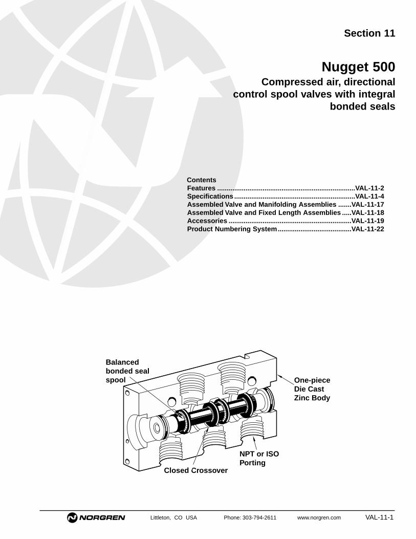
Littleton, CO USA Phone: 303-794-2611 www.norgren.com VAL-11-1
Section 11
ContentsFeatures .........................................................................VAL-11-2Specifications ................................................................VAL-11-4Assembled Valve and Manifolding Assemblies .......VAL-11-17Assembled Valve and Fixed Length Assemblies .....VAL-11-18Accessories .................................................................VAL-11-19Product Numbering System.......................................VAL-11-22
Nugget 500Compressed air, directional
control spool valves with integralbonded seals
Balancedbonded sealspool
NPT or ISO Porting
One-pieceDie CastZinc Body
Closed Crossover

VAL-11-2 Littleton, CO USA Phone: 303-794-2611 www.norgren.com
Nugget 500 Series Valves
Design Features Provide High Reliability.Norgren Nugget 500 Valves feature a precision spool with integralbonded seals. This design provides superior performance, fast andeasy maintenance, dependable operation, and long life. Other keyfeatures and benefits include:
Two-Year Unconditional WarrantyAll Nugget valves are warranted to be free from defects for a full twoyears from the date of purchase. This extended warranty periodprovides users with a valuable guarantee of quality andserviceability.
Two Valve ConfigurationsNugget 500 are available in a 5-Port/2-Position or 5-Port/3-Positionconfiguration.
A Wide Range of Valve AccessoriesNorgren offers a number of accessories for use with the Nugget 500Valve, including valve body cover plates, speed control kits, mufflers,intermediate supply/exhaust block, solenoid exhaust filters, manifoldblanking plates, and isolating plugs. These accessories allow cost-effective customizing for your specific application.
Small Subbase FootprintAll subbase valves mount on approximately 1.50" ( 38 mm) centers,reducing installation space requirements.
High FlowA Cv of 5.0 provides exceptionally high flow for the compact size ofthe valve, making the Nugget 500 appropriate for machine controland general purpose industrial applications.
Nitrile Rubber-Based SealsAll Norgren Nugget 500 Valves utilize nitrile O-rings and seals forsuperior compatibility, wear, and operation over a wide temperaturerange.
Port and Operator IdentificationEach of the ports is identified by a permanent number adjacent tothe port on the body or subbase. In addition, a two-digit number ateach end of the valve body indicates the ports connected when theoperator at that end is actuated. Port and operator identification onNugget 500 Valves comply with ANSI and NFPA T3.21.15-1989. SeeOperating Variations on page VAL-9-5 for examples.
Durable FinishExternal valve body, operator and subbasesurfaces are protected with an oven cured,epoxy resin paint that provides excellentcorrosion and chip-resistant protection.
Quality AppearanceNorgren's high luster black gives any controlcircuit installation a quality appearance reflectingthe superior operating capability built into everyNugget 500 Valve.
Four Mounting StylesInline Valves have two sets of mounting holesrunning through the valve body. Inline valves maybe bolted to a surface or may be supported byconnecting piping.
Fixed Length Manifolds allow the installation ofinline valves on a competitively priced commonmanifold. For quick installation, valves areattached to the manifold with two socket headcap screws. Valves share common supply andexhaust galleries in the manifold.
A single Subbase Valve is attached to a SingleSubbase with four socket head cap screws,providing easy installation. Inlet, exhaust,external pilot supply and cylinder ports arelocated on the sides of the subbase.
Subbase Valves are attached to ManifoldingSubbases with four socket head cap screws.Subbases are held together with a clamping pinand set screw combination, which reducespotential leaks and allows quick assembly ofvalve stations. Common inlet and exhaust portsand common external pilot supply ports arelocated in the end plates. Cylinder ports arelocated in the ends of the subbases.
Closed CrossoverThe design of the Nugget spool ensures that noair flow occurs between supply port 1 andexhaust ports 3 & 5, preventing the waste ofcompressed air.
Fixed Length Manifold

Littleton, CO USA Phone: 303-794-2611 www.norgren.com VAL-11-3
Nugget 500 Series Valves
Operator ChoicesSolenoid pilot and air pilot operators are available for primaryactuation and return operation. For secondary operation air-assistedspring return, spring return and integral air return operators areoffered.
Low Wattage Solenoid OperatorsAC and DC operators requiring only 3.5 and 2.0 watts of power,respectively, are ideal for computer based control systems as well asindustrial applications where minimum energy consumption isdesired. Faster response times are realized using the 7.5 watt ACand DC operators.
Solenoid Exhaust FilterOptional solenoid exhaust filters, for use in dusty environments, areavailable.
Solenoid Diffuser PlugA diffuser plug installed in the pilot exhaust helps prevent entry ofcontaminants during shipping and normal operation. It may beremoved when minimum response times are desired.
Rotatable Connector and CoilThe standard cable grip connector can be rotated 180°, and thesolenoid coil can be turned 360° in 90° increments, making theoperators adaptable for easy installation.
Electrical Connector OptionsA cable grip electrical connector with indicator light; a 1/2" NPTconduit connector and a 5-foot, three-conductor, molded cableconnector with or without indicator light and surge suppression areavailable.
Solenoid Manual OverridesStandard solenoid operators are furnished with manual non-lockingoverrides to provide a means of shifting the valve without electricalpower. Optional solenoids without overrides or with locking overridesare also available.
Internal or External Solenoid Pilot SupplyAll inline solenoid operated valves may bequickly converted from an internal to an externalpilot supply by reversing a one-piece sealbetween the operator and the body andremoving the external supply port pipe plug. Allsubbase solenoid operated valves may bequickly converted from an internal pilot to acommon external pilot supply by rotating a one-piece seal between the valve body and thesubbase to provide pilot pressure from theexternal pilot supply port in the single subbase orendplate.
Sintered Bronze Vent FiltersInternal parts are protected by built-in sinteredbronze vent filters on operators.
High Flow Pilot Exhaust OrificeAn oversized pilot exhaust orifice provides rapidreturn time when the valve is deactuated.
Single Subbase Valve
Inline Double Solenoid Valve
Manifolding Subbase Valve

VAL-11-4 Littleton, CO USA Phone: 303-794-2611 www.norgren.com
Nugget 500 Series Valves
SpecificationsOperating SpecificationsFluids: Filtered, lubricated or nonlubricated, compressed air or vacuum service.Inlet Pressure Range:
Solenoid Operated Valves:*With Internal Pilot Supply:20 to 150 psig (1.4 to 10.3 bar)
With External Pilot Supply:26" Hg** to 150 psig (26" Hg** to 10.3 bar)
Air Operated Valves: 26" Hg** to 150 psig (26" Hg** to 10.3 bar).Temperature Range (Ambient & Inlet):
Solenoid Operated Valves: -20°F to 120°F† (-29°C to 50°C).Air Operated Valves: -20°F to 160°F†(-29°C to 71°C).
Operator Pilot Pressures:Maximum Pressure: 150 psig (10.3 bar)Minimum Pressure requirements are given in the table below:
* Solenoid operators must be externally piloted if the supply pressure to the mainvalve is below the minimum pilot pressure listed in the table below.
** With vacuum supply plumbed to an exhaust port.†With dewpoint of supply air less than air temperature below 35°F (2°C).Port Size (PTF Standard, ISO Optional)
Inline Valves: 3/8" & 1/2" PTF standard, (ISO G optional); 3/4" PTF onlyInline Valve Fixed Length Manifold: 3/4" PTF inlet and exhaust ports standard
(ISO G optional).Single Subbase: 3/8" or 1/2" PTF standard (ISO G optional); 1/8" PTF or ISO G
external pilot supply.Manifolding Subbase: 3/8" or 1/2" PTF standard (ISO G optional) cylinder
ports.End Plates for Manifolding Subbases: 3/4" PTF standard (ISO G optional) inlet
and exhaust ports;1/8" PTF or ISO G external pilot supply.
Operator: 1/8" PTF or ISO G external pilot supply port.Special Order Threads: ISO Rc – Consult Factory.
Valve Materials
Body: AluminumSpool: AluminumElastomers: NitrileSolenoid Operator Base: PPS PlasticOperator Housing: Zinc
Speed Control Materials
Body: ZincAdjusting Screw: BrassElastomers: Nitrile
Subbase Materials
Fixed Length Manifold: AluminumSingle & Manifolding Subbases: AluminumEnd Plate: ZincElastomers: NitrileSolenoid Operator SpecificationsVoltages and Power Requirements:
Standard:120V/60Hz-110V/50Hz: 3.5W.
Optional:24V/60Hz-24V/50Hz: 3.5W;6 VDC: 2.0W;12 VDC: 2.0W;24 VDC: 2.0W;110 VDC: 3.4W.120V/60Hz-110V/50Hz: 7.5W;240V/60Hz-220V/50Hz: 7.5W;24V/60Hz-24V/50Hz: 7.5W;12 VDC: 7.5W;24 VDC: 6.0W.
Duty: Continuous at 90 to 105 % of rated voltage.Coil Type: Class H. Molded with three-pin electrical plug-
in connector.Enclosure Classification: NEMA 4, and DIN 40050-IP65.Electrical spade connections on the operator receptacle
conform to industry standard form B for 3-pinconnectors with 11 mm spacing.
Electrical Plug-in Connector: Cable grip for cables 1/4"to 5/16" (6 to 8 mm) in diameter.
Override: Non-locking, locking or no overrideExternal Pilot Supply Port: 1/8" PTF or ISO G
Average Flow Factor (Cv)†
3/8", 1/2", & 3/4" Ported Valves: 4.0, 5.0, & 5.6,respectively.†Flow rating determined in accordance with ANSI(NFPA).T3.21.3, Pneumatic fluid power – Flow testprocedure and reporting method – for fixed orificecomponents.
Operator Pilot PressuresMaximum Pressure: 150 psig (10.3 bar)Minimum Pilot Pressures are given in the following table
Minimum Operating PressurePrimary Secondary Nondetent Detent Spring CenteredOperator Return Oper psig (bar) psig (bar) psig (bar)
Air Air 20 (1.4) 30 (2.1) 40 (2.8)Solenoid Solenoid 20 (1.4) 30 (2.1) 40 (2.8)Solenoid Spring 40 (2.8) — —Solenoid Air-Assisted Spring 40 (2.8) — —Solenoid Integral Air 40 (2.8) — —
Air Spring 40 (2.8) — —Air Air-Assisted Spring 40 (2.8) — —Air Integral Air 40 (2.8) — —

Littleton, CO USA Phone: 303-794-2611 www.norgren.com VAL-11-5
Nugget 500 Series Valves
Dual Sandwich Speed Control
Seal CompatibilityNugget 500 seals are compatible with most goodquality O-ring lubricants, including:
DC BR-2+ grease (Dow Corning)DC 44 grease (Dow Corning)Parker Super O-Lube (Parker Seal)Magnalube G (Saunders Industries)Nondetergent mineral based oil such as MobilDTE light oil
Nugget 500 seals are not compatible with WD-40 orcommonly used de-icer fluids. Consult factory to verifycompatibility of lubricants or fluids not listed above.
2 3 1 5 4
Air Pilot Solenoid Pilot Solenoid Pilot Detent Air PilotDetent
Air Pilot Solenoid Pilot Solenoid Pilot Detent Air PilotDetent
Primary Operators
Secondary Operators
Air Assisted Spring Integral Air
Spring
42
3 1 5
1 2 1 4
42
3 1 5
1 2 1 4
2 4
1 53
1 2 1 4
2 4
1 53
1 2 1 4
2 4
1 53
1 2 1 42 4
1 53
1 2 1 4
Spool Option 01 Spool Option 02
Spool Option 03 Spool Option 04
Spool Option 05 Spool Option 06
Single Pressure Single Pressure†
5-Port / 2-Position
5-port / 3-positonspring centered, allports blocked in the center positon*
5-port / 3-positionspring centeredcylinder open to exhaustin the center position*
* 5-post / 3-position valves available with double solenoid pilot or double air pilot operators only† Dual presssure valves require externally piloted operators
Operating Variations

5/2 and 5/2 directional control spool valves
VAL-11-6 Littleton, CO USA Phone: 303-794-2611 www.norgren.com
Nugget 500 Series Valves
● Long lasting spool design
● High flow compact valves
● Four mounting styles: inline, fixed lengthmanifolds, single subbase, or subbase valvesattached to manifolding subbases
● Wide range of operators available
● Two functional types: available in 5/2, and 5/3configurations
Technical DataMedium:
Filtered, lubricated or non-lubricated, compressed air or vacuumOperation:
Spool valve air pilot actuatedMounting:
Inline, fixed length manifold, single subbase, and manifolding subbasePort Sizes:
3/8", 1/2", or 3/4", ISO G or PTFOperating Pressure:
Maximum 150 psig (10.3 bar).Flow Characteristics:
Port Cv l/min scfm3/8" Inline 4.0 4250 1501/2" Inline 5.0 5150 1803/4" Inline 5.6 6000 2101/2" Subbase 4.7 5300 190
Operating TemperatureSolenoid Operated Valves: -20° to 120°F (-29° to 50°C)Air Operated Valves: -20° to 160°F (-29° to 71°C)*Consult our Technical Service for use below 36°F (2°C)
Materials:Valve Body: AluminumSpool: AluminumElastomers: NitrileSolenoid Operator Base: PPS plasticOperator Housing: Zinc
Speed Control MaterialsBody: ZincAdjusting Screw: BrassElastomers: Nitrile
Subbase MaterialsFixed Length Manifolds: AluminumSingle and Manifolding Subbase: AluminumEnd Plate: ZincElastomers: Nitrile
Order InformationTo order standard Nugget 500 air pilot solenoidoperated valves, quote model number from table,e.g. orderMN01CGA-35-AJJA for a 5-port/2-position, singlesolenoid, spring return model.

Littleton, CO USA Phone: 303-794-2611 www.norgren.com VAL-11-7
Nugget 500 Series Valves
FLOW CHARACTERISTICS3/8" Ported Inline Valves
20 60 100 140 180 psig
600
500
400
300
200
100
0
50
100
150
200
250
300
0 2 4 6 8 10 12 14 bar
ABCDEF
dm
3 /s
scfm
Inlet PressureA = 150 psig (10.3)B = 120 psig (8.3)C = 90 psig (6.2)D = 60 psig (4.1)E = 40 psig (2.8)F = 20 psig (1.4)
FLOW CHARACTERISTICS1/2" Ported Inline Valves
20 60 100 140 180 psig
600
500
400
300
200
100
0
50
100
150
200
250
300
0 2 4 6 8 10 12 14 bar
ABCDEF
Inlet PressureA = 150 psig (10.3)B = 120 psig (8.3)C = 90 psig (6.2)D = 60 psig (4.1)E = 40 psig (2.8)F = 20 psig (1.4)
dm
3 /s
scfm
FLOW CHARACTERISTICS3/4" Ported Inline Valves
20 60 100 140 180 psig
600
500
400
300
200
100
0
50
100
150
200
250
300
0 2 4 6 8 10 12 14
ABCDEF
Inlet PressureA = 150 psig (10.3)B = 120 psig (8.3)C = 90 psig (6.2)D = 60 psig (4.1)E = 40 psig (2.8)F = 20 psig (1.4)
dm
3 /s
scfm
SPEED CONTROLInlet Pressure: 90 PSIG (6 .2 bar)Flow Path: 2 to 3 and 4 to 5 (cyl to exhaust)
120
100
80
60
40
20 10
20
30
40
50
60
0 1 2 3 4 5 6 7 8 9 10
140
Needle Valve Turns Open
dm
3 /s
scfm

VAL-11-8 Littleton, CO USA Phone: 303-794-2611 www.norgren.com
Nugget 500 Series Valves
Inline ValvesPilot
Port Pressure Weight RepairDescription Symbol Type Size Body Operator psig (bar) lbs. (kg) Kit
5-port/2-position1/2" PTF MN01CGA 35-AJJA
40 - 150 1.42 54677-50Single Solenoid single pressure (2.8 - 10.3) (.65)
Spring Return* 5-port/2-position1/2" PTF MN02CGA 35-AKJA
40 - 150 1.42 54677-51dual pressure (2.8 - 10.3) (.65)
5-port/2-position1/2" PTF MN01CGA 25-AJJA
20 - 150 1.71 54677-50Double single pressure (1.4 - 10.3) (.78)
Solenoid 5-port/2-position1/2" PTF MN02CGA 25-AJJA
20 - 150 1.71 54677-51dual pressure (1.4 - 10.3) (.78)
5-port/2 position1/2" PTF MN01CGA 25-BJJA
30 - 150 1.99 54677-50Double Solenoid single pressure (2.1 - 10.3) (.90)
Detent 5-port/2 position1/2" PTF MN02CGA 25-BJJA
30 - 150 1.99 54677-51dual pressure (2.1 - 10.3) (.90) 54677-51
5-port/3-positionsingle pressure,
1/2" PTF MN03CGA 25-FJJA40 - 150 1.99 54677-52
all ports blocked in (2.8 - 10.3) (.90)Double center position
Solenoid 5-port/3-position1/2" PTF MN04CGA 25-FJJA
40 - 150 1.99 54677-53dual pressure, (2.8 - 10.3) (.90)
all ports blocked incenter position
5-port/3-position1/2" PTF MN05CGA 25-FJJA
20 - 150 1.99 54677-54Double Solenoid single pressure, (1.4 - 10.3) (.90)Spring Centered cylinder open toCylinder Open exhaust
to Exhaust5-port/3-position dual
1/2" PTF MN06CGA 25-FJJA20 - 150 1.99 54677-55
pressure cylinder (1.4 - 10.3) (.90)open to exhaust
42
3 1 542
3 1 52 4
3 1 52 4
3 1 52 4
3 1 52 4
3 1 5
2 4
1 53
2 4
1 53
2 4
1 53
2 4
1 53
* Standard valves are equipped with PTF threads, solenoid operators with non-locking overrides, internal pilot, 120V/60 Hz-110V/50 Hz coils and cablegrip connectors. Optional solenoid operators, coil voltages and electrical connectors can be ordered using the information on p. VAL-11-22.
Note: For ISO-G threads, insert “G” in the 7th position.

Littleton, CO USA Phone: 303-794-2611 www.norgren.com VAL-11-9
Nugget 500 Series Valves
Inline Valves
PilotPort Pressure Weight Repair
Description Symbol Type Size Body Operator psig (bar) lbs. (kg) Kit
5-port/2-position1/2" PTF MN01CGA 33-A000
40 - 150 1.1654677-50
Single Air single pressure (2.8 - 10.3) (.53)
Spring Return* 5-port/2-position1/2" PTF MN02CGA 33-A000
40 - 150 1.1654677-51
dual pressure (2.8 - 10.3) (.53)
5-port/2-position1/2" PTF MN01CGA 23-A000
20 - 150 1.1654677-50
Double single pressure (1.4 - 10.3) (.53)
Air 5-port/2-position1/2" PTF MN02CGA 23-A000
20 - 150 1.1654677-51
dual pressure (1.4 - 10.3) (.53)
5-port/2 position1/2" PTF MN01CGA 23-B000
30 - 150 1.4254677-50
Double Air single pressure (2.1 - 10.3) (.65)
Detent 5-port/2 position1/2" PTF MN02CGA 23-B000
30 - 150 1.4254677-51
dual pressure (2.1 - 10.3) (.65)
5-port/3-positionsingle pressure,
1/2" PTF MN03CGA 23-F00040 - 150 1.42
54677-52all ports blocked in (2.8 - 10.3) (.65)
Double Air, center position
Spring Centered,5-port/3-position
1/2" PTF MN04CGA 23-F00040 - 150 1.42 54677-53
all ports blocked dual pressure,(2.8 - 10.3) (.65)all ports blocked in
center position5-port/3-position
1/2" PTF MN05CGA 23-F000 20 - 150 1.42 54677-54Double Air single pressure, (1.4 - 10.3) (.65)
Spring Centered cylinder open to
Cylinder Open exhaust
to Exhaust 5-port/3-position dual1/2" PTF MN06CGA 23-F000
20 - 150 1.4254677-55
pressure, cylinder (1.4 - 10.3) (.65)open to exhaust
24
3 1 542
3 1 52 4
3 1 52 4
3 1 52 4
3 1 52 4
3 1 5
2 4
1 53
2 4
1 53
2 4
1 53
* Standard valves are equipped with PTF threads..Note: For ISO-G threads, insert “G” in the 7th position.
2 4
1 53

VAL-11-10 Littleton, CO USA Phone: 303-794-2611 www.norgren.com
Nugget 500 Series Valves
Valves with Manifolding Subbases
PilotPort Pressure Weight Repair
Description Symbol Type Size Body Operator psig (bar) lbs. (kg) Kit
5-port/2-position1/2" PTF MN01GGA 35-AJJA
40 - 150 2.3754677-50
Single Solenoid single pressure (2.8 - 10.3) (1.08)
Spring Return* 5-port/2-position1/2" PTF MN02GGA 35-AKJA
40 - 150 2.3754677-51
dual pressure (2.8 - 10.3) (1.08)
5-port/2-position1/2" PTF MN01GGA 25-AJJA
20 - 150 2.6454677-50
Double single pressure (1.4 - 10.3) (1.20)
Solenoid 5-port/2-position1/2" PTF MN02GGA 25-AJJA
20 - 150 2.6454677-51
dual pressure (1.4 - 10.3) (1.20)
5-port/2 position1/2" PTF MN01GGA 25-BJJA
30 - 150 2.94 54677-50Double Solenoid single pressure (2.1 - 10.3) (1.34)
Detent 5-port/2 position1/2" PTF MN02GGA 25-BJJA
30 - 150 2.94 54677-51dual pressure (2.1 - 10.3) (1.34) 54677-51
5-port/3-positionsingle pressure,
1/2" PTF MN03GGA 25-FJJA40 - 150 2.94
54677-52all ports blocked in (2.8 - 10.3) (1.34)
Double center position
Solenoid 5-port/3-position1/2" PTF MN04GGA 25-FJJA
40 - 150 2.9454677-53
dual pressure, (2.8 - 10.3) (1.34)all ports blocked in
center position
5-port/3-position1/2" PTF MN05GGA 25-FJJA
20 - 150 2.9454677-54
Double Solenoid single pressure, (1.4 - 10.3) (1.34)Spring Centered cylinder open toCylinder Open exhaust
to Exhaust 5-port/3-position dual1/2" PTF MN06GGA 25-FJJA
20 - 150 2.9454677-55
pressure cylinder (1.4 - 10.3) (1.34)open to exhaust
42
3 1 52 4
3 1 52 4
3 1 52 4
3 1 52 4
3 1 52 4
3 1 5
2 4
1 53
2 4
1 53
2 4
1 53
2 4
1 53
* Standard valves are equipped with PTF threads, solenoid operators with non-locking overrides, internal pilot, 120V/60 Hz-110V/50 Hz coils and cable grip connectors.Optional solenoid operators, coil voltages and electrical connectors can be ordered using the information on p. VAL-11-22.
Note: For ISO-G threads, insert “G” in the 7th position.

Littleton, CO USA Phone: 303-794-2611 www.norgren.com VAL-11-11
Nugget 500 Series Valves
Valves with Manifolding Subbases
PilotPort Pressure Weight Repair
Description Symbol Type Size Body Operator psig (bar) lbs. (kg) Kit
5-port/2-position 1/2" PTF MN01GGA 33-A000 40 - 150 2.09 54677-50Single Air single pressure (2.8 - 10.3) (.95)
Spring Return* 5-port/2-position 1/2" PTF MN02GGA 33-A000 40 - 150 2.09 54677-51dual pressure (2.8 - 10.3) (.95)
5-port/2-position 1/2" PTF MN01GGA 23-A000 20 - 150 2.09 54677-50Double single pressure (1.4 - 10.3) (.95)
Air 5-port/2-position 1/2" PTF MN02GGA 23-A000 20 - 150 2.09 54677-51dual pressure (1.4 - 10.3) (.95)
5-port/2 position 1/2" PTF MN01GGA 23-B000 30 - 150 2.37 54677-50Double Air single pressure (2.1 - 10.3) (1.08)
Detent 5-port/2 position 1/2" PTF MN02GGA 25-B000 30 - 150 2.37 54677-51dual pressure (2.1 - 10.3) (1.08)
5-port/3-positionsingle pressure, 1/2" PTF MN03GGA 23-F000 40 - 150 2.37 54677-52
all ports blocked in (2.8 - 10.3) (1.08)Double Air, center position
Spring Centered, 5-port/3-position 1/2" PTF MN04GGA 23-F000 40 - 150 2.37 54677-53all ports blocked dual pressure, (2.8 - 10.3) (1.08)
all ports blocked incenter position
5-port/3-position 1/2" PTF MN05GGA 23-F000 20 - 150 2.37 54677-54Double Air single pressure, (1.4 - 10.3) (1.08)
Spring Centered cylinder open toCylinder Open exhaust
to Exhaust 5-port/3-position dual 1/2" PTF MN06GGA 23-F000 20 - 150 2.37 54677-55pressure, cylinder (1.4 - 10.3) (1.08)open to exhaust
24
3 1 542
3 1 52 4
3 1 52 4
3 1 52 4
3 1 52 4
3 1 5
2 4
1 53
2 4
1 53
2 4
1 53
2 4
1 53
* Standard valves are equipped with PTF threads.Note: For ISO-G threads, insert “G” in the 7th position.

VAL-11-12 Littleton, CO USA Phone: 303-794-2611 www.norgren.com
Nugget 500 Series Valves
Valves on a Single Subbase
PilotPort Pressure Weight Repair
Description Symbol Type Size Body Operator psig (bar) lbs. (kg) Kit
5-port/2-position 1/2" PTF MN01EGA 35-AJJA 40 - 150 2.08 54677-50Single Solenoid single pressure (2.8 - 10.3) (.95)
Spring Return* 5-port/2-position 1/2" PTF MN02EGA 35-AKJA 40 - 150 2.08 54677-51dual pressure (2.8 - 10.3) (.95)
5-port/2-position 1/2" PTF MN01EGA 25-AJJA 20 - 150 2.33 54677-50Double single pressure (1.4 - 10.3) (1.06)
Solenoid 5-port/2-position 1/2" PTF MN02EGA 25-AJJA 20 - 150 2.33 54677-51dual pressure (1.4 - 10.3) (1.06)
5-port/2 position 1/2" PTF MN01EGA 25-BJJA 30 - 150 2.62 54677-50Double Solenoid single pressure (2.1 - 10.3) (1.19)
Detent 5-port/2 position 1/2" PTF MN02EGA 25-BJJA 30 - 150 2.62 54677-51dual pressure (2.1 - 10.3) (1.19) 54677-51
5-port/3-positionsingle pressure, 1/2" PTF MN03EGA 25-FJJA 40 - 150 2.62 54677-52
all ports blocked in (2.8 - 10.3) (1.19)Double center position
Solenoid 5-port/3-position 1/2" PTF MN04EGA 25-FJJA 40 - 150 2.62 54677-53dual pressure, (2.8 - 10.3) (1.19)
all ports blocked incenter position
5-port/3-position 1/2" PTF MN05EGA 25-FJJA 20 - 150 2.62 54677-54Double Solenoid single pressure, (1.4 - 10.3) (1.19)Spring Centered cylinder open toCylinder Open exhaust
to Exhaust 5-port/3-position dual 1/2" PTF MN06EGA 25-FJJA 20 - 150 2.62 54677-55pressure cylinder (1.4 - 10.3) (1.19)open to exhaust
42
3 1 52 4
3 1 52 4
3 1 52 4
3 1 52 4
3 1 52 4
3 1 5
2 4
1 53
2 4
1 53
2 4
1 53
2 4
1 53
* Standard valves are equipped with PTF threads, solenoid operators with non-locking overrides, internal pilot, 120V/60 Hz-110V/50 Hz coils and cable grip connectors.Optional solenoid operators, coil voltages and electrical connectors can be ordered using the information on p. VAL-11-22.
Note: For ISO-G threads, insert “G” in the 7th position.

Littleton, CO USA Phone: 303-794-2611 www.norgren.com VAL-11-13
Nugget 500 Series Valves
Valves on a Single Subbase
PilotPort Pressure Weight Repair
Description Symbol Type Size Body Operator psig (bar) lbs. (kg) Kit
5-port/2-position 1/2" PTF MN01EGA 33-A000 40 - 150 1.81 54677-50Single Air single pressure (2.8 - 10.3) (.82)
Spring Return* 5-port/2-position 1/2" PTF MN02EGA 33-A000 40 - 150 1.81 54677-51dual pressure (2.8 - 10.3) (.82)
5-port/2-position 1/2" PTF MN01EGA 23-A000 20 - 150 1.81 54677-50Double single pressure (1.4 - 10.3) (.82)
Air 5-port/2-position 1/2" PTF MN02EGA 23-A000 20 - 150 1.81 54677-51dual pressure (1.4 - 10.3) (.82)
5-port/2 position 1/2" PTF MN01EGA 23-B000 30 - 150 2.09 54677-50Double Air single pressure (2.1 - 10.3) (.95)
Detent 5-port/2 position 1/2" PTF MN02EGA 23-B000 30 - 150 2.09 54677-51dual pressure (2.1 - 10.3) (.95)
5-port/3-positionsingle pressure, 1/2" PTF MN03EGA 23-F000 40 - 150 2.09 54677-52
all ports blocked in (2.8 - 10.3) (.95)Double Air, center position
Spring Centered, 5-port/3-position 1/2" PTF MN04EGA 23-F000 40 - 150 2.09 54677-53all ports blocked dual pressure, (2.8 - 10.3) (.95)
all ports blocked incenter position
5-port/3-position 1/2" PTF MN05EGA 23-F000 20 - 150 2.09 54677-54Double Air single pressure, (1.4 - 10.3) (.95)
Spring Centered cylinder open toCylinder Open exhaust
to Exhaust 5-port/3-position dual 1/2" PTF MN06EGA 23-F000 20 - 150 2.09 54677-55pressure, cylinder (1.4 - 10.3) (.95)open to exhaust
24
3 1 542
3 1 52 4
3 1 52 4
3 1 52 4
3 1 52 4
3 1 5
2 4
1 53
2 4
1 53
2 4
1 53
2 4
1 53
* Standard valves are equipped with PTF threads.Note: For ISO-G threads, insert “G” in the 7th position.
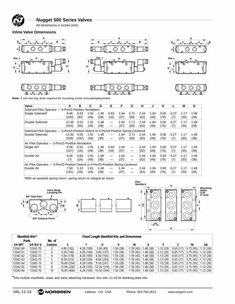
VAL-11-14 Littleton, CO USA Phone: 303-794-2611 www.norgren.com
Nugget 500 Series Valves
Valve A B C D E F G H J K L M NSolenoid Pilot Operator — 5-Port/2-Position NondetentSingle Solenoid* 9.46 3.53 1.91 1.48 0.63 1.44 2.71 2.44 1.94 3.00 0.27 1.17 1.48
(240) (90) (49) (38) (16) (37) (69) (62) (49) (76) (7) (30) (38)
Double Solenoid 12.36 3.53 1.91 1.48 — 1.44 2.71 2.44 1.94 3.00 0.27 1.17 1.48(314) (90) (49) (38) — (37) (69) (62) (49) (76) (7) (30) (38)
Solenoid Pilot Operator — 5-Port/2-Position Detent or 5-Port/3-Position Spring CenteredDouble Solenoid 13.30 4.00 1.91 1.48 — 1.44 2.71 2.44 1.94 3.00 0.27 1.17 1.48
(338) (102) (49) (38) — (37) (69) (62) (49) (76) (7) (30) (38)
Air Pilot Operator — 5-Port/2-Position Nondetent Single Air* 6.56 0.63 1.91 1.48 0.63 1.44 — 2.44 1.94 3.00 0.27 1.17 1.48
(167) (16) (49) (38) (16) (37) — (62) (49) (76) (7) (30) (38)
Double Air 6.56 0.63 1.91 1.48 — 1.44 — 2.44 1.94 3.00 0.27 1.17 1.48(7) (16) (49) (38) — (37) — (62) (49) (76) (7) (30) (38)
Air Pilot Operator — 5-Port/2-Position Detent or 5-Port/3-Position Spring CenteredDouble Air 7.50 1.10 1.91 1.48 — 1.44 — 2.44 1.94 3.00 0.27 1.17 1.48
(191) (28) (49) (38) — (37) — (62) (49) (76) (7) (30) (38)
*With air-assisted spring return, spring return or integral air return
Manifold Kits* Fixed Length Manifold Kits and Dimensions Ports No. of
3/4 NPT 3/4 ISO G Stations S T U V W X Y Z TA UA13342-60 13342-70 2 4.00 (102) 4.28 (109) 3.50 (89) 1.50 (38) 1.78 (45) 1.48 (38) 1.13 (29) 0.65 (17) 3.75 (95) 1.12 (28)13342-61 13342-71 3 5.50 (140) 4.28 (109) 5.00 (127) 1.50 (38) 1.78 (45) 1.48 (38) 1.13 (29) 0.65 (17) 3.75 (95) 1.12 (28)13342-62 13342-72 4 7.00 (178) 4.28 (109) 6.50 (165) 1.50 (38) 1.78 (45) 1.48 (38) 1.13 (29) 0.65 (17) 3.75 (95) 1.12 (28)13342-63 13342-73 5 8.50 (216) 4.28 (109) 8.00 (203) 1.50 (38) 1.78 (45) 1.48 (38) 1.13 (29) 0.65 (17) 3.75 (95) 1.12 (28)13342-64 13342-74 6 10.00 (254) 4.28 (109) 9.50 (241) 1.50 (38) 1.78 (45) 1.48 (38) 1.13 (29) 0.65 (17) 3.75 (95) 1.12 (28)13342-65 13342-75 8 13.00 (330) 4.28 (109) 12.50 (318) 1.50 (38) 1.78 (45) 1.48 (38) 1.13 (29) 0.65 (17) 3.75 (95) 1.12 (28)13342-66 13342-76 10 16.00 (406) 4.28 (109) 15.50 (394) 1.50 (38) 1.78 (45) 1.48 (38) 1.13 (29) 0.65 (17) 3.75 (95) 1.12 (28)
C
G
JHF
K
N N MM
C BE D
A
Dia. L
C
G
K
N N MM
C BB D
A
Dia. L
F
C
JH
K
N N MM
C BB D
A
Dia. L
Z
Y Y
W
X X
3/4'' Inlet Port
Valve BodyLocating Pin
3/4" Exhaust Ports
W
51
3
51
3
TA VT
U
S
UA
MountingHoles0.28(7 mm)
PortNumbers
Note: 4 mm hex key drive required for mounting screw removal/replacement
Inline Valve Dimensions
*Kits include manifolds, seals, and valve attaching hardware. See VAL-11-19 for blanking plate kits.
All Dimensions in Inches (mm)

Littleton, CO USA Phone: 303-794-2611 www.norgren.com VAL-11-15
Nugget 500 Series Valves
Valve A B C D E F G H J K L N O P R S T
Solenoid Pilot Operator — 5-Port/2-Position NondetentSingle Solenoid* 0.63 1.94 1.48 1.46 0.48 9.46 1.80 4.15 3.53 1.38 0.63 6.50 6.05 1.48 0.25 2.71 0.63
(16) (49) (38) (37) (12) (240) (46) (105) (90) (35) (16) (1.65) (154) (38) (6) (69) (16)
Double Solenoid 0.63 1.94 1.48 1.46 0.48 10.40 1.80 4.15 4.00 1.38 0.63 6.50 6.05 1.48 0.25 2.71 0.63(16) (49) (38) (37) (12) (264) (46) (105) (102) (35) (16) (1.65) (154) (38) (6) (69) (16)
Solenoid Pilot Operator — 5-Port/2-Position Detent or 5-Port/3-Position Spring CenteredDouble Solenoid 0.63 1.94 1.48 1.46 0.48 12.36 1.80 4.15 3.53 1.38 0.63 6.50 6.05 1.48 0.25 2.71 0.63
(16) (49) (38) (37) (12) (314) (46) (105) (90) (35) (16) (1.65) (154) (38) (6) (69) (16)
Air Pilot Operator — 5-Port/2-Position NondetentSingle Air* 0.63 1.94 1.48 1.46 0.48 6.56 1.80 3.89 — 1.38 0.63 6.50 6.05 1.48 0.25 — 0.63
(16) (49) (38) (37) (12) (167) (46) (99) — (35) (16) (1.65) (154) (38) (6) — (16)
Double Air 0.63 1.94 1.48 1.46 0.48 6.56 1.80 3.89 — 1.38 0.63 6.50 6.05 1.48 0.25 — 0.63(16) (49) (38) (37) (12) (167) (46) (99) — (35) (16) (1.65) (154) (38) (6) — (16)
Air Pilot Operator — 5-Port/2-Position Detent or 5-Port/3-Position Spring CenteredDouble Air 0.63 1.94 1.48 1.46 0.48 7.50 1.80 3.89 — 1.38 0.63 6.50 6.05 1.48 0.25 — 0.63
(16) (49) (38) (37) (12) (191) (46) (99) — (35) (16) (1.65) (154) (38) (6) — (16)
*With air-assisted spring return, spring return or integral air return.
Single Subbase Ports
A T
D
G
RK
L
H
F
P P
J
ON
B EC
A T
D
G
RK
L
H
S
F
P P
J
ON
B EC
A T
D
GL
RKH
F
P PON
B EC
Valve BodyLocating Pin
3/8" ExternalPilot Port
3/8" or 1/2"Exhaust Ports
1/8" ExternalPilot Port
Port Numbers
3/8" or 1/2"Cylinder Ports
4.250 (108)
.280 (7)
1.12
0(2
8)
Note: 4 mm hex key drive required for mounting screws
Subbase Valve on Single Subbase Dimensions
All Dimensions in Inches (mm)
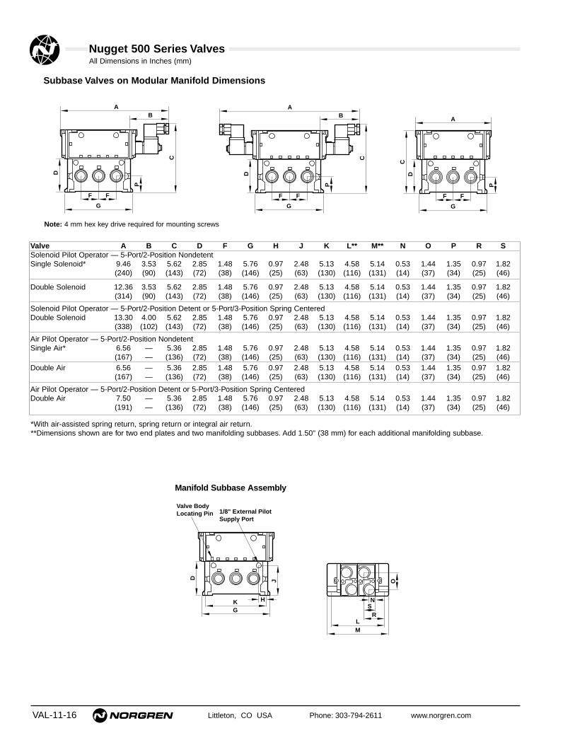
All Dimensions in Inches (mm)
VAL-11-16 Littleton, CO USA Phone: 303-794-2611 www.norgren.com
Nugget 500 Series Valves
Valve A B C D F G H J K L** M** N O P R SSolenoid Pilot Operator — 5-Port/2-Position Nondetent Single Solenoid* 9.46 3.53 5.62 2.85 1.48 5.76 0.97 2.48 5.13 4.58 5.14 0.53 1.44 1.35 0.97 1.82
(240) (90) (143) (72) (38) (146) (25) (63) (130) (116) (131) (14) (37) (34) (25) (46)
Double Solenoid 12.36 3.53 5.62 2.85 1.48 5.76 0.97 2.48 5.13 4.58 5.14 0.53 1.44 1.35 0.97 1.82(314) (90) (143) (72) (38) (146) (25) (63) (130) (116) (131) (14) (37) (34) (25) (46)
Solenoid Pilot Operator — 5-Port/2-Position Detent or 5-Port/3-Position Spring CenteredDouble Solenoid 13.30 4.00 5.62 2.85 1.48 5.76 0.97 2.48 5.13 4.58 5.14 0.53 1.44 1.35 0.97 1.82
(338) (102) (143) (72) (38) (146) (25) (63) (130) (116) (131) (14) (37) (34) (25) (46)
Air Pilot Operator — 5-Port/2-Position Nondetent Single Air* 6.56 — 5.36 2.85 1.48 5.76 0.97 2.48 5.13 4.58 5.14 0.53 1.44 1.35 0.97 1.82
(167) — (136) (72) (38) (146) (25) (63) (130) (116) (131) (14) (37) (34) (25) (46)Double Air 6.56 — 5.36 2.85 1.48 5.76 0.97 2.48 5.13 4.58 5.14 0.53 1.44 1.35 0.97 1.82
(167) — (136) (72) (38) (146) (25) (63) (130) (116) (131) (14) (37) (34) (25) (46)
Air Pilot Operator — 5-Port/2-Position Detent or 5-Port/3-Position Spring CenteredDouble Air 7.50 — 5.36 2.85 1.48 5.76 0.97 2.48 5.13 4.58 5.14 0.53 1.44 1.35 0.97 1.82
(191) — (136) (72) (38) (146) (25) (63) (130) (116) (131) (14) (37) (34) (25) (46)
Manifold Subbase Assembly
*With air-assisted spring return, spring return or integral air return.**Dimensions shown are for two end plates and two manifolding subbases. Add 1.50" (38 mm) for each additional manifolding subbase.
C
D
P
F F
G
BA
C
D
P
F F
G
BA
CD
P
F F
G
A
JD
K H
G
Valve BodyLocating Pin 1/8" External Pilot
Supply Port
O
R
N
LM
S
Note: 4 mm hex key drive required for mounting screws
Subbase Valves on Modular Manifold Dimensions

Littleton, CO USA Phone: 303-794-2611 www.norgren.com VAL-11-17
Nugget 500 Series Valves
For ordering information, the valve andmanifolding subbase assembly are orientedwith the 1 2 operator end on the left side,and the 1 4 operator end on the right side.The valves are listed from FRONT to BACK.This example illustrates how to order a valveand manifolding subbase assembly, withisolating plugs for two different workingpressures installed between valve manifoldsubbases 2 and 3.Four pipe plugs are included with the endplate kit to allow blocking of unused commoninlet, exhaust, and pilot end plate ports toprevent air loss and entry of contaminants.
ValvePos. Product SpecialNo. Qty. Number Instructions1 1 MN01GCA-75-ALJA2 1 MN01GGA-75-ALJA
1 54676-50 Install isolating
plugs3 1 MN01GGA-75-ALJA4 1 MN01GGA-75-ALJA
1 13338-50 End Plate kit4 99-059-530 Ass’y charge
Factory Assembled Valve and Manifolding Subbase Assemblies
Isolating Plug KitsAn isolating plug kit is available to allow theuse of different inlet pressures. A valve andmanifolding subbase assembly can bedivided into two sections by insertingisolating plugs between any two manifoldingsubbases.The drawing at right illustrates a valve andmanifolding subbase assembly separatedfor a two pressure applications by isolatingplugs.
Ordering Information
Isolating Plug Kit* 54676-50*Kit contains 3-Isolating Plugs
Port 23/8" or 1/2"
Cylinder Ports
Port 43/8" or 1/2"
Cylinder Ports
Set Screw
End Plate
Seal
Isolating Plugs
Separator
Clamping Pin
Valve 1
Valve 2Valve 3
Valve 4
Port 33/4" CommonExhaust Port
Port 13/4" Common
Inlet PortPort 5
3/4" CommonExhaust Port
1/8 ExternalPilot Supply Port
FRONT
BACK
1 2 END
1 4 END

VAL-11-18 Littleton, CO USA Phone: 303-794-2611 www.norgren.com
Nugget 500 Series Valves
Factory Assembled Valve and Fixed Length Assemblies
Valve 1
Valve 2
Valve 3
1 2 END
Valve 4Valve 5
1/2" CylinderPorts
BACK
1 4 END
Port 53/4" CommonExhaust Port
Port 13/4" Common
Inlet Port
Port 33/4" CommonExhaust Port
FRONT
For ordering information, the valve and manifold assemblyis oriented with the 1 2 operator end on the left side andthe 1 4 operator end on the right side. The valves are listedfrom FRONT to BACK.e.g. to order a five station, fixed length manifold assembly:
ValvePos. ProductNo. Qty. Number
1-3 3 MN01CGA-75-AJJA4 1 MN01CGA-25-AJJA5 1 MN03CGA-25-FJJA
1 13342-634 33-059-530 (Ass’y Chg)
Special Instructions: One assembly consisting of theNugget stack above.

Littleton, CO USA Phone: 303-794-2611 www.norgren.com VAL-11-19
Nugget 500 Series Valves
Blanking Plate KitThe blanking plate kit consists of a blanking plate, seal, and attaching hardware.The plate is installed on a subbase in place of a valve, allowing an additional valveto be added at a later date.
For Fixed LengthManifolds: 54689-50
For Single and Manifolding Subbases: 54689-51
Quietaire® Mufflers and Speed Control MufflersMufflers should be installed in the exhaust ports of Nugget 500 Valves to reducework area noise and help prevent contaminants from entering the valve. Speedcontrol mufflers also allow metering of the exhaust air flow to restrict the speed ofair cylinders and air motors. Do not use speed control mufflers in manifold exhaustports.
Port Sintered SpeedSize Type Control ShellNPT Muffler Muffler Type
3/8 MS003A MM003A MB003A1/2 MS004A MM004A MB004A3/4 MS006A MM006A MB006A
See Norgren publication APC-101 for complete muffler information.
Intermediate Supply/Exhaust BlockThe intermediate supply/exhaust block consists of asupply/exhaust block, a manifolding subbase valve bodywithout spool, interface seals and hardware needed toconnect the subbase to the adjacent subbase and sixisolating plugs. The supply/exhaust block provides amethod of connecting an additional air supply to the valvemanifold. This helps prevent starvation of supply air to thevalves when a number of valves are operatedsimultaneously. The block also allows use of three or moresupply pressures in the same manifold, and may also beused to exhaust individual valves.
Supply/Exhaust Block1/2" PTF .......................................................54693-501/2" ISO G....................................................54693-51
Dual Sandwich Speed Control KitThe speed control kit, consisting of a speed control block, mountingscrews, and gasket, is installed between a subbase valve and a subbase.Needle valves, located at both ends of the speed control, restrict exhaustflow from the valve to control the speed of an air cylinder or motor. Orderthe speed control kit below.
Speed Control Kit ..............................13336-60
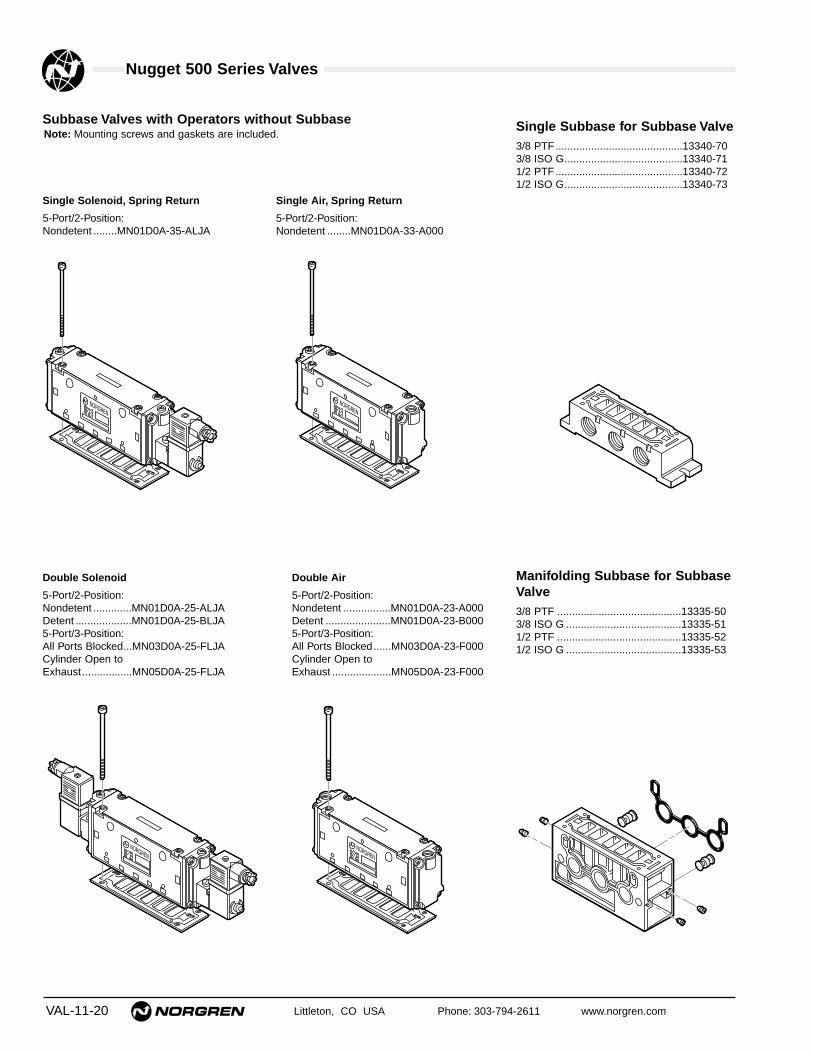
VAL-11-20 Littleton, CO USA Phone: 303-794-2611 www.norgren.com
Single Solenoid, Spring Return
5-Port/2-Position:Nondetent ........MN01D0A-35-ALJA
Nugget 500 Series Valves
Double Solenoid
5-Port/2-Position:Nondetent .............MN01D0A-25-ALJADetent ...................MN01D0A-25-BLJA5-Port/3-Position:All Ports Blocked...MN03D0A-25-FLJACylinder Open toExhaust.................MN05D0A-25-FLJA
Manifolding Subbase for SubbaseValve3/8 PTF ..........................................13335-503/8 ISO G .......................................13335-511/2 PTF ..........................................13335-521/2 ISO G .......................................13335-53
Single Subbase for Subbase Valve3/8 PTF...........................................13340-703/8 ISO G........................................13340-711/2 PTF...........................................13340-721/2 ISO G........................................13340-73
Double Air
5-Port/2-Position:Nondetent ................MN01D0A-23-A000Detent ......................MN01D0A-23-B0005-Port/3-Position:All Ports Blocked......MN03D0A-23-F000Cylinder Open toExhaust ....................MN05D0A-23-F000
Single Air, Spring Return
5-Port/2-Position:Nondetent ........MN01D0A-33-A000
Subbase Valves with Operators without SubbaseNote: Mounting screws and gaskets are included.

Littleton, CO USA Phone: 303-794-2611 www.norgren.com VAL-11-21
Nugget 500 Series Valves
Factory Installed Back Cover Plates for Valve BodiesThe Back Cover Plate ordered with the valve allows the valve to be used in wash-down environments such as food or medical processing. If a subbase valve isdesired for wash-down environments, use only the single subbase.● For cover plate installed on an Inline Valve body specify with 54690-11 after the
valve body number.● For cover plate installed on a Subbase Valve body specify with 54690-12 after
the valve body number.
Pneu-Fit Push-in Tube FittingsPush-in tube fittings are an excellent way to save valve connection time andsimplify component replacement. See Norgren Fittings catalog APC-101 for acomplete selection of push-in tube fittings, flexible tubing, tubing markers, and tubemounts.
Part Numbers for Replacement Solenoid Coils & ArmatureBasesSolenoid Coils:
24V/60Hz-24V/50Hz, 3.5W ...........54469-04120V/60Hz-110V/50Hz, 3.5W .......54469-036VDC, 2W .....................................54469-0512VDC, 2W ...................................54469-0124VDC, 2W ...................................54469-02110VDC, 3.4W ..............................54469-06240V/60Hz-220V/50Hz, 7.5W .......54452-07120V/60Hz-110V/50Hz, 7.5W .......54452-0124V/60Hz-24V/50Hz, 7.5W ...........54452-0512VDC, 7.5W ...............................54452-0224VDC, 6W ..................................54452-03
Solenoid Base and Armature:Without Override6 to 7.5 Watt ................................54462-012 to 3.5 Watt ................................54462-03
With Locking Override6 to 7.5 Watt ................................54462-022 to 3.5 Watt ................................54462-04With Non-Locking Override6 to 7.5 Watt ................................54462-092 to 3.5 Watt ................................54462-10
Part Numbers for Replacement ConnectorsCable Grip Connector.......................54934-01Cable Grip Connector with
Indicator Light110/120 VAC/DC ..........................54934-0224 VAC/DC ...................................54934-08
1/2" NPT Conduit .............................54934-05Molded 5-ft Cable Connector
0-220 VAC/DC ..............................54934-21Molded 5-ft Cable Connector with
Indicator Light and surge suppression24 VAC/DC ...................................54934-30110 VAC/DC .................................54934-35240 VAC/DC .................................54934-37
Part Numbers for Repair Parts & KitsMetal Coil Retaining Ring..................54453-01Solenoid Connector Seal Kit .............54935-01Solenoid Exhaust Port Diffuser .........54463-01Solenoid Exhaust Port Filter
Ordered With Valve .......................54463-50Ordered Separately .......................54463-51
Spool Replacement Kits: ...................Single Pressure, 2-Position ...........54677-50Dual Pressure, 2-Position..............54677-51Single Pressure, 3-Position,All Ports Blocked*.........................54677-52
Dual Pressure, 3-Position,All Ports Blocked*.........................54677-53
Single Pressure, 3-Position,Cylinder Open to Exhaust* ..........................54677-54Dual Pressure, 3-Position, Cylinder Open to Exhaust* ..........................54677-55*In the center position
Seal KitsInline Valves ..................................54692-50Subbase Valves.............................54692-51Inline Valve to Fixed Length Manifold.............................54674-89Subbase Valve to Subbase ....................................54672-89Manifolding Subbase toEnd Plates.....................................54673-89
Manifold clampingpin (1) & set screws (2) .................54574-50
Mounting Screws Valve to FixedLength Manifold or Subbase .........54580-60
Mounting Screws Valve and Speed Control to Subbase............54580-61

Nugget 500 Series Valves
VAL-11-22 Littleton, CO USA Phone: 303-794-2611 www.norgren.com
Type & Family
Basic Size
Internal Variations
Mounting
Port Size
Thread Type
Secondary Operator 1 2 End
Primary Operator 1 4 End
Operator Description
Solenoid Override/Pilot Supply
Coil Voltage/Wattage
Electrical Connector
M = Bonded Spool Valve
N = Nugget 500, Cv = 5.0
01 = 5-Port/2-Position, Single Pressure Valve02 = 5-port/2-Position, Dual Pressure Valve03 = 5 Port/3-Position, Single Pressure Valve, Spring Centered, All Ports Blocked04 = 5 Port/3-Position, Dual Pressure Valve, Spring Centered, All Ports Blocked05 = 5-Port/3-Position, Single Pressure Valve, Spring Centered, Cylinder Open to Exhaust06 = 5-Port/3-Position, Dual Pressure Valve, Spring Centered, Cylinder Open to Exhaust
C = 5-Port, Inline Valve
D = 5-Port, Subbase ValveWithout Subbase
E = 5-Port Subbase ValveAssembled to a SingleSubbase
G = 5-Port, SubbaseValve Assembled to aManifolding Subbase
A = PTFG = ISO
3 = Air Pilot5 = Solenoid Pilot
Position 1 2 3 4 5 6 7 8 9 10 11 12 13
1
2
3 4
5
6
7
8
9
10
11
12
13
Valve Body Operator Description
0 = Use for Air Operator
Operators
= Product Number
3.5 Watt, NominalJ = 120V/60Hz-110V/50 Hz, 3.5 WattL = 24V/60Hz/50z, 3.5 WattM = 6VDC, 2 WattN = 12 VDC, 2 WattP = 24 VDC, 2 WattS = 110 VDC, 3.4 Watt
A = Cable GripB = Cable Grip with Indicator Light 110/120 VAC/DCC = 1/2" NPT ConduitD = 5-ft Molded Cable 0-220 VAC/DCE = 5-ft Molded Cable with Indicator Light and Surge Suppression, 24 VAC/DC G = 5-ft Molded Cable with Indicator Light and Surge Suppression, 110 VAC/DCH = 5-ft Molded Cable with Indicator Light and Surge Suppression, 240 VAC/DCJ = Cable Grip with Indicator Light, 24 VAC/DCX = Solenoid Without Connector
F = 3/8"G = 1/2"
F = 3/8"G = 1/2"H = 3/4" (PTF only)
1 = Integral Air Return2 = Same as Primary Operator3 = Spring Return7 = Air-Assisted Spring Return
A = NondetentB = DetentF = Spring Centered
0 = Use for Air Operator
7.5 Watt, NominalN = No Override, Internal PilotP = No Override, External PilotR = Non-Locking Override, Internal PilotS = Non-Locking Override, External PilotT = Locking Override, Internal PilotV = Locking Override, External Pilot
7.5 Watt, NominalT = 120V/60Hz-110V/50Hz, 7.5 WattV = 240V/60Hz-220V/50Hz, 7.5 WattW = 24V/60Hz/50Hz, 7.5 WattZ = 12 VDC, 7.5 Watt1 = 24 VDC, 6.0 Watt
3.5 Watt, NominalG = No Override, Internal PilotH = No Override, External PilotJ = Non-Locking Override, Internal PilotK = Non-Locking Override, External PilotL = Locking Override, Internal PilotM = Locking Override, External Pilot
— —
0 = Subbase Valve Without Subbase
0 = Use for Air Operator

Littleton, CO USA Phone: 303-794-2611 www.norgren.com VAL-12-1
Section 12
Field convertibleexternal pilot portallows easy adaptability
Internal pilot passage checkvalve to eliminate reverseflow in high flow applications
Permanent port identificationadjacent to each port onbody or subbase to assistduring installation
Aluminum alloyconstruction treatedto resist corrosion
Through mounting holessuitable for wall mounting
Short-stroke, positive sealing,cushioned poppet
Reversible poppet-seals provide abuilt-in repair kit
Nitrile elastomers for superiorcompatibility, wear and operation overa wide temperature range
External surfaces are protected with an ovencured, epoxy resin paint providing excellentcorrosion protection and chip resistance.
ContentsFeatures . . . . . . . . . . . . . . . . . . . . . . . . . . . . . . . . . . . .VAL-12-21/4" to 2" Solenoid Pilot Actuated 2/2, 3/2,and 4/2 Inline and Subbase Valves . . . . . . . . . . . . . . .VAL-12-41/4" to 2" Air Pilot Actuated 2/2, 3/2,and Inline and Subbase Valves . . . . . . . . . . . . . . . . .VAL-12-201/4" to 2" Manual and Mechanical Actuated2/2, 3/2, and 4/2 Inline and Subbase Valves . . . . . . .VAL-12-32
Smooth Start Valves and Time Delay Options . . . . .VAL-12-46Lockouts . . . . . . . . . . . . . . . . . . . . . . . . . . . . . . . . . .VAL-12-54Flow Factors . . . . . . . . . . . . . . . . . . . . . . . . . . . . . . .VAL-12-58Part Numbering System . . . . . . . . . . . . . . . . . . . . . .VAL-12-60
Prospector Series Poppet Valves
Compressed Air Directional Control Poppet Valves
Socket head cap screws,for ease of maintenance

VAL-12-2 Littleton, CO USA Phone: 303-794-2611 www.norgren.com
Prospector Series Poppet Valves
Design Features Provide High Reliability.
Norgren Prospector Valves feature a short-stroke, positive-sealing,cushioned poppet. This rugged, simple design eliminates metal-to-metal contact, insuring long life and trouble free operation. Shockabsorption by the resilient mass of the poppet seals virtuallyeliminates the impact damage common to other designs. Worn ordamaged poppet seals can be turned over, considerablyextending their service life before replacement is necessary. Withthese reversible seals, the valve may be said to carry its ownspare parts for quick and economical maintenance.
High FlowA Cv of 1.2 to 49.5 provides exceptionally high flow, makingProspector Poppet Valves appropriate for a wide range ofindustrial applications.
Valve AccessoriesProspector Poppet Valve accessories include a footguard for foot-actuated valves, time delays for use with air and solenoidoperators, mufflers, push-in tube fittings, and optional solenoidoperators.
Nitrile Rubber-Based SealsAll Norgren Prospector Valves utilize nitrile O-rings and seals forsuperior compatibility, wear, and operation over a widetemperature range.
Port IdentificationEach of the ports is identified by a permanent marking adjacent tothe port on the body or subbase.
Two Mounting StylesAll Prospector Valves are manufactured withmounting holes and are available as inlinemounted valves. The 4-port/2-position (4-way)valves are also available in a single subbasemounted style. Subbase valves are attachedto a single subbase with six socket head capscrews, providing providing easy removal andinstallation.
Durable FinishExternal surfaces are protected with an ovencured, epoxy resin paint which providesexcellent corrosion and chip resistantprotection.
Aesthetic AppearanceNorgren's high luster black gives any controlcircuit installation the quality appearancereflecting the superior operating capability builtinto every Prospector Valve.

Littleton, CO USA Phone: 303-794-2611 www.norgren.com VAL-12-3
Prospector Series Poppet Valves
Standard Solenoid Operator FeaturesRotatable Connector and CoilThe standard cable grip connector used on basic 1/4" and 1/2"valves can be rotated 180°, and the solenoid coil can be turned inincrements of 90°, making the operators adaptable for easyinstallation. The standard cable grip connector used on basic 1"and 2" valves can be turned in increments of 90°.
Low Wattage Solenoid OperatorsThe standard solenoid operator used on basic 1/4" and 1/2"valves requires only 6 WDC and 7 WAC of power. It is available ina low wattage option that requires only 2 WDC and 3.5 WAC. Thestandard solenoid operator used on basic 1" and 2" valvesrequires 8 WAC and DC.
Solenoid Diffuser PlugA diffuser plug installed in the pilot exhaust on basic 1/4" and 1/2"valves helps prevent entry of contaminants during shipping andnormal operation. It may be removed when minimum responsetimes are desired.
Electrical Connector IdentificationUp to three lettered or numbered plates snap into a slot moldedinto the standard cable grip connector to identify that operatorwithin the system.
Solenoid Manual Overrides.Standard solenoid operators are furnished witha nonlocking manual override to provide ameans of shifting the valve without electricalpower. Optional solenoid operators with alocking override, or without an override, arealso available.
High Flow Pilot Exhaust Orifice.Oversize pilot exhaust orifice provides rapidreturn time when valve is de-energized.
Electrical Connector Options.A cable grip connector with indicator light; a1/2" NPT conduit connector; and a 5- foot,three-conductor, molded cable with or withoutindicator light, surge protection and reversevoltage protection are available.

VAL-12-4 Littleton, CO USA Phone: 303-794-2611 www.norgren.com
Prospector Series Poppet Valves
2-Port/2-PositionThese 2-way valves have an inlet and outlet port and are used as
shutoff valves that open or close an air line. They are available innormally closed or normally open models. The normally closedmodel blocks flow when in its normal position, and permits flow whenit is actuated. The normally open model permits flow when in itsnormal position, and blocks flow when actuated. Typical applicationsinclude on-off control of main plant air, air to branch lines, systemsand air motors.
Flow Diagrams
3-Port/2-Position These 3-way valves have an inlet, outlet, and exhaust port and are
typically used to pressurize and then exhaust air from such devicesas single-acting cylinders. They are available in normally closed ornormally open models. The normally closed model exhausts airfrom the device when in its normal position, and pressurizes thedevice when actuated. The normally open model pressurizes thedevice when in its normal position and exhausts air from the devicewhen actuated.
The normally closed valve is available with two options: a positionindicator pin and an air or solenoid momentary signal operator.The indicator pin can be used to operate a switch or other device toprovide a signal for a control circuit. The momentary signaloperator is used when it is desirable to control the valve with twoalternately applied momentary signals (first signal shifts and holds thepoppet; the second allows the poppet to return to its normal position).
Flow Diagrams
NORMAL ACTUATED
NormallyClosed
NormallyOpen
NormallyClosed
NormallyOpen
NORMAL ACTUATED
Inlet Blocked Pressure to OUT Port
3-Port/2-Position (Multi-Directional)
These 3-way valves can be used in fourdifferent ways — as a distributor, directing airfirst to one port, then to another; as a selector,directing first high, then low pressure air (orvacuum) to the same outlet; as a standard 3-port/2-position normally closed valve; and as astandard 3-port/2-position normally open *valve. Multi-directional valves are the only poppetvalves with which speed controls can be installedin the exhaust port.Flow Diagrams
NORMAL ACTUATED
Distributor
Selector(TwoPressure)
NormallyClosed
NormallyOpen *
* Normally open valves require anexternal pilot supply.
Pressure to OUT Port Inlet Blocked
Pressure to Port A Inlet Blocked
Inlet Blocked Pressure to Port A
Pressure C to Port A Pressure B to Port A
Pressure to Port C Pressure to Port B
Inlet Blocked Pressure to Port B
Pressure to Port B Inlet Blocked
A(IN)
B(OUT)
A(IN)
B(OUT)
A(IN)
B(OUT)
A(IN)
B(OUT)
IN
OUTEXH
IN
OUTEXH
IN
OUT
EXH
IN
OUT
EXH
A(IN)
B(OUT)
C (OUT 1)
A(IN)
B(OUT 2)
C (OUT 1)
B(IN 2)
A(OUT)
C (IN 1)
B(IN 2)
A(OUT)
C (IN 1)
B(IN)
A(OUT)
C (EXH)
B(IN)
A(OUT)
C (EXH)
B(EXH)
A(OUT)
C (IN)
B(EXH)
A(OUT)
C (IN)
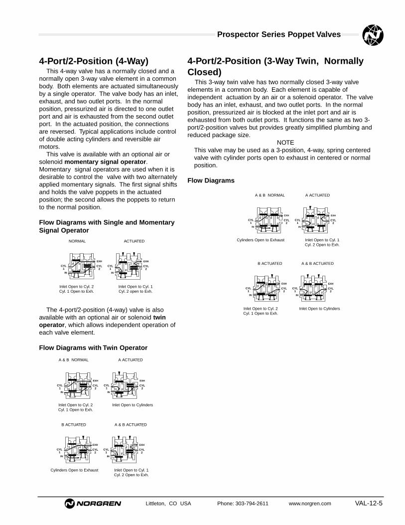
Littleton, CO USA Phone: 303-794-2611 www.norgren.com VAL-12-5
Prospector Series Poppet Valves
4-Port/2-Position (4-Way)This 4-way valve has a normally closed and a
normally open 3-way valve element in a commonbody. Both elements are actuated simultaneouslyby a single operator. The valve body has an inlet,exhaust, and two outlet ports. In the normalposition, pressurized air is directed to one outletport and air is exhausted from the second outletport. In the actuated position, the connectionsare reversed. Typical applications include controlof double acting cylinders and reversible airmotors.
This valve is available with an optional air orsolenoid momentary signal operator.Momentary signal operators are used when it isdesirable to control the valve with two alternatelyapplied momentary signals. The first signal shiftsand holds the valve poppets in the actuatedposition; the second allows the poppets to returnto the normal position.
Flow Diagrams with Single and MomentarySignal Operator
The 4-port/2-position (4-way) valve is alsoavailable with an optional air or solenoid twinoperator, which allows independent operation ofeach valve element.
Flow Diagrams with Twin Operator
NORMAL ACTUATED
A & B NORMAL A ACTUATED
B ACTUATED A & B ACTUATED
4-Port/2-Position (3-Way Twin, NormallyClosed)
This 3-way twin valve has two normally closed 3-way valveelements in a common body. Each element is capable ofindependent actuation by an air or a solenoid operator. The valvebody has an inlet, exhaust, and two outlet ports. In the normalposition, pressurized air is blocked at the inlet port and air isexhausted from both outlet ports. It functions the same as two 3-port/2-position valves but provides greatly simplified plumbing andreduced package size.
NOTEThis valve may be used as a 3-position, 4-way, spring centeredvalve with cylinder ports open to exhaust in centered or normalposition.
Flow Diagrams
A & B NORMAL A ACTUATED
B ACTUATED A & B ACTUATED
Cylinders Open to Exhaust Inlet Open to Cyl. 1Cyl. 2 Open to Exh.
Inlet Open to Cyl. 2 Inlet Open to Cylinders Cyl. 1 Open to Exh.
Cylinders Open to Exhaust Inlet Open to Cyl. 1Cyl. 2 Open to Exh.
Inlet Open to Cyl. 2 Inlet Open to Cylinders Cyl. 1 Open to Exh.
Inlet Open to Cyl. 2 Inlet Open to Cyl. 1 Cyl. 1 Open to Exh. Cyl. 2 open to Exh.
CYL1
IN
CYL2
EXH
CYL1
IN
CYL2
EXH
CYL1
IN
CYL2
EXH
CYL1
IN
CYL2
EXH
CYL1
IN
CYL2
EXH
CYL1
IN
CYL2
EXH
CYL1
IN
CYL2
EXH
CYL1
IN
CYL2
EXH
CYL1
IN
CYL2
EXH
CYL1
IN
CYL2
EXH

VAL-12-6 Littleton, CO USA Phone: 303-794-2611 www.norgren.com
● High flow - Cv of 1.2 to 49.5
● Durable, robust construction
● Two mounting styles: inline or subbase
● 1/4" to 2" ports (BSPP, PTF, or ISO Rc threads)
● Wide range of voltages available
● Four functional types: available in 2/2, 3/2, 3/2
multi-directional, and 4/2 configurations
1/4" to 2" Solenoid Pilot Actuated 2/2, 3/2, & 4/2 Inline and Subbase Valves
Technical DataMedium:
Filtered and lubricated or non-lubricated compressed air or vacuum.
Operation:Poppet valve solenoid pilot actuated.
Mounting:Through-holes in valve body and subbase.
Port Size:1/4" to 2" PTF, BSPP, or ISO Rc.
Operating Pressure:Maximum 150 psig (10.3 bar).
Flow Characteristics:Basic Size Function Cv* l/min1/4" 3/2 & 4/2 1.2 - 1.8 984 - 2,4351/2" 2/2, 3/2 & 4/2 3.2 - 5.8 3,398 - 6,2301" 2/2, 3/2 & 4/2 10.3 - 17.7 4,474 - 15,3482" 2/2 & 3/2 39.6 - 49.5 38,228 - 54,085*See VAL-12-58 for additional flow information.
Operating Temperature:-20°F to 120°F** (-29°C to 49°C)**Consult Technical Service for use below 34°F (+2°C).
Materials:Body: Aluminum alloy body, piston, poppets and subbase.Operators: Zinc or aluminum solenoid pilot operators, stainless steel orsteel, reinforced polyester, brass or polyurethane, acetal, copper wire.Elastomers: Nitrile rubber seals. (Fluorocarbon seals are optional,contact Technical Services.)
Ordering InformationTo order standard poppet valves with coils, quote modelnumber and voltage code from tables overleaf, e.g.order D1024C-00-CY1W6 for a 3-port, 2-position,normally closed, Solenoid Pilot Operated, SpringReturn model with an internal pilot supply, fitted with a 240/220V, 60/50Hz coil, and manual non-locking override.
CYL2 CYL1
IN EXH
4-Way
3-Port/2-Position Multi-Directional
OUTB
AIN
Normally ClosedOUT
B
AIN
Normally Open
3-Port/2-Position
4-Port/2-Position
2-Port/2-Position
IN
OUTEXH
This example shows a 3-waynormally closed valve.
EXH IN
OUT
Normally Closed
B C
OUTA
Normally Open
C BEXH IN
OUTA
Normally Closed
B CEXH IN
OUTA
Normally Open
OUT2 OUT1
AIN
B C
Distributor
IN2 IN1
OUTA
B C
Selector

Littleton, CO USA Phone: 303-794-2611 www.norgren.com VAL-12-7
Prospector Series Poppet Valves
Solenoid Pilot Operated Spring Return Inline and Subbase Valves2-Port/2-Position (2 way) Inline, Normally ClosedBelow listed operators have non-locking override and 110/120V 50/60Hz coil.
† External Pilot Supply: Pilot supply pressure must be equal to or greater than the operating pressure. § Repair Kit: Kits contain all elastomers necessary to service one valve body.
Symbol Solenoid Basic Port Model Operating Pilot Weight Repair Kit§Pilot Size Size Pressure Pressure lbs. (kg)
psig (bar) psig (bar)
Internal Pilot 1/4" A1012C-00-CY30 - 150 30 - 150 2.12
53474-03(2.1 - 10.3) (2.1 - 10.3) (1.01)
3/8" A1013C-00-CY30 - 150 30 - 150 2.22
53474-03(2.1 - 10.3) (2.1 - 10.3) (1.01)
1/2"1/2" A1014C-00-CY
30 - 150 30 - 150 2.2253474-03
(2.1 - 10.3) (2.1 - 10.3) (1.01)
3/4" A1015C-00-CY30 - 150 30 - 150 2.22
53474-03(2.1 - 10.3) (2.1 - 10.3) (1.01)
3/4" A1025C-00-CC30 - 150 30 - 150 4.40
53475-01(2.1 - 10.3) (2.1 - 10.3) (2.00)
1" A1026C-00-CC30 - 150 30 - 150 4.40
53475-011"(2.1 - 10.3) (2.1 - 10.3) (2.00)
1-1/4" A1027C-00-CC30 - 150 30 - 150 4.40
53475-01(2.1 - 10.3) (2.1 - 10.3) (2.00)
1-1/2" A1038C-00-CC30 - 150 30 - 150 4.40
53822-01(2.1 - 10.3) (2.1 - 10.3) (3.98)
2"2" A1039C-00-CC
30 - 150 30 - 150 8.7653822-01
(2.1 - 10.3) (2.1 - 10.3) (3.98)
External Pilot 1/4" A1012H-00-CY0 - 150 30 - 150 2.12
53474-03(0 - 10.3) (2.1 - 10.3†) (1.01)
3/8" A1013H-00-CY0 - 150 30 - 150 2.22
53474-03(0 - 10.3) (2.1 - 10.3†) (1.01)
1/2"1/2" A1014H-00-CY
0 - 150 30 - 150 2.2253474-03
(10 - 10.3) (2.1 - 10.3†) (1.01)
3/4" A1015H-00-CY0 - 150 30 - 150 2.22
53474-03(0 - 10.3) (2.1 - 10.3†) (1.01)
3/4" A1025H-00-CC0 - 150 30 - 150 4.40
53475-01(0 - 10.3) (2.1 - 10.3†) (2.00)
1" A1026H-00-CC0 - 150 30 - 150 4.40
53475-011"(0 - 10.3) (2.1 - 10.3†) (2.00)
1-1/4" A1027H-00-CC0 - 150 30 - 150 4.40
53475-01(0 - 10.3) (2.1 - 10.3†) (2.00)
1-1/2" A1038H-00-CC0 - 150 30 - 150 4.40
53822-01(0 - 10.3) (2.1 - 10.3†) (3.98)
2"2" A1039H-00-CC
0 - 150 30 - 150 8.7653822-01
(0 - 10.3) (2.1 - 10.3†) (3.98)
OUTB
AIN
OUTB
AIN

Prospector Series Poppet Valves
VAL-12-8 Littleton, CO USA Phone: 303-794-2611 www.norgren.com
2-Port/2-Position (2 way) Inline, Normally OpenBelow listed operators have non-locking override and 110/120V 50/60Hz coil.
Symbol Solenoid Basic Port Model Operating Pilot Weight Repair Kit§Pilot Size Size Pressure Pressure lbs. (kg)
psig (bar) psig (bar)
Internal Pilot 1/4" B1012C-00-CY30 - 150 30 - 150 2.22
53474-03(2.1 - 10.3) (2.1 - 10.3) (1.01)
3/8" B1013C-00-CY30 - 150 30 - 150 2.22
53474-03(2.1 - 10.3) (2.1 - 10.3) (1.01)
1/2"1/2" B1014C-00-CY
30 - 150 30 - 150 2.2253474-03
(2.1 - 10.3) (2.1 - 10.3) (1.01)
3/4" B1015C-00-CY30 - 150 30 - 150 2.22
53474-03(2.1 - 10.3) (2.1 - 10.3) (1.01)
3/4" B1025C-00-CC30 - 150 30 - 150 4.40
53475-01(2.1 - 10.3) (2.1 - 10.3) (2.00)
1"1" B1026C-00-CC
30 - 150 30 - 150 4.4053475-01
(2.1 - 10.3) (2.1 - 10.3) (2.00)
1-1/4" B1027C-00-CC30 - 150 30 - 150 4.40
53475-01(2.1 - 10.3) (2.1 - 10.3) (2.00)
External Pilot 1/4" B1012H-00-CY0 - 150 30 - 150 2.22
53474-03(0 - 10.3) (2.1 - 10.3†) (1.01)
3/8" B1013H-00-CY0 - 150 30 - 150 2.22
53474-03(0 - 10.3) (2.1 - 10.3†) (1.01)
1/2"1/2" B1014H-00-CY
0 - 150 30 - 150 2.2253474-03
(0 - 10.3) (2.1 - 10.3†) (1.01)
3/4" B1015H-00-CY0 - 150 30 - 150 2.22
53474-03(0 - 10.3) (2.1 - 10.3†) (1.01)
3/4" B1025H-00-CC0 - 150 30 - 150 4.40
53475-01(0 - 10.3) (2.1 - 10.3†) (2.00)
1"1" B1026H-00-CC
0 - 150 30 - 150 4.4053475-01
(0 - 10.3) (2.1 - 10.3†) (2.00)
1-1/4" B1027H-00-CC0 - 150 30 - 150 4.40
53475-01(0 - 10.3) (2.1 - 10.3†) (2.00)
† External Pilot Supply: Pilot supply pressure must be equal to or greater than the operating pressure. § Repair Kit: Kits contain all elastomers necessary to service one valve body.
OUTB
AIN
OUTB
AIN

Littleton, CO USA Phone: 303-794-2611 www.norgren.com VAL-12-9
Prospector Series Poppet Valves
Symbol Solenoid Basic Port Model Operating Pilot Weight Repair Kit§Pilot Size Size Pressure Pressure lbs. (kg)
psig (bar) psig (bar)
Internal Pilot 1/4" D1012B-00-CY30 - 150 30 - 150 1.91
53473-051/4"
(2.1 - 10.3) (2.1 - 10.3) (0.87)
3/8" D1013B-00-CY30 - 150 30 - 150 1.91
53473-05(2.1 - 10.3) (2.1 - 10.3) (0.87)
1/4" D1022C-00-CY30 - 150 30 - 150 2.50
53474-03(2.1 - 10.3) (2.1 - 10.3) (1.13)
3/8" D1023C-00-CY30 - 150 30 - 150 2.50
53474-031/2"
(2.1 - 10.3) (2.1 - 10.3) (1.13)
1/2" D1024C-00-CY30 - 150 30 - 150 2.50
53474-03(2.1 - 10.3) (2.1 - 10.3) (1.13)
3/4" D1025C-00-CY30 - 150 30 - 150 2.50
53474-03(2.1 - 10.3) (2.1 - 10.3) (1.13)
3/4" D1035C-00-CC30 - 150 30 - 150 4.49
53475-01(2.1 - 10.3) (2.1 - 10.3) (2.04)
1" 1" D1036C-00-CC30 - 150 30 - 150 4.49
53475-01(2.1 - 10.3) (2.1 - 10.3) (2.04)
1-1/4" D1047C-00-CC30 - 150 30 - 150 4.49
53475-01(2.1 - 10.3) (2.1 - 10.3) (2.04)
External Pilot 1/4" D1012H-00-CY0 - 150 30 - 150 1.91
53473-051/4"
(0 - 10.3) (2.1 - 10.3†) (0.87)
3/8" D1013H-00-CY0 - 150 30 - 150 1.91
53473-05(0 - 10.3) (2.1 - 10.3†) (0.87)
1/4" D1022H-00-CY0 - 150 30 - 150 2.50
53474-03(0 - 10.3) (2.1 - 10.3†) (1.13)
3/8" D1023H-00-CY0 - 150 30 - 150 2.50
53474-031/2"
(0 - 10.3) (2.1 - 10.3†) (1.13)
1/2" D1024H-00-CY0 - 150 30 - 150 2.50
53474-03(0 - 10.3) (2.1 - 10.3†) (1.13)
3/4" D1025H-00-CY0 - 150 30 - 150 2.50
53474-03(0 - 10.3) (2.1 - 10.3†) (1.13)
3/4" D1035H-00-CC0 - 150 30 - 150 4.49
53475-01(0 - 10.3) (2.1 - 10.3†) (2.04)
1" 1" D1036H-00-CC0 - 150 30 - 150 4.49
53475-01(0 - 10.3) (2.1 - 10.3†) (2.04)
1-1/4" D1047H-00-CC0 - 150 30 - 150 4.49
53475-01(0 - 10.3) (2.1 - 10.3†) (2.04)
3-Port/2-Position (3 way) Inline, Normally ClosedBelow listed operators have non-locking override and 110/120V 50/60Hz coil.
† External Pilot Supply: Pilot supply pressure must be equal to or greater than the operating pressure. § Repair Kit: Kits contain all elastomers necessary to service one valve body.
EXH IN
OUT
EXH IN
OUT
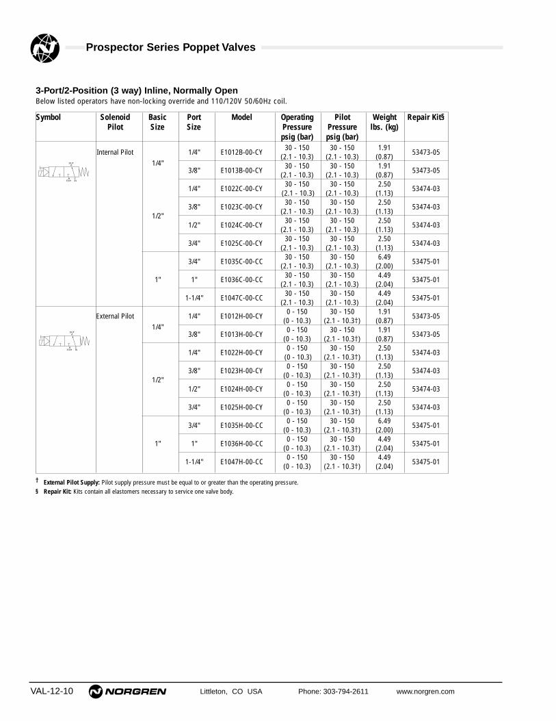
VAL-12-10 Littleton, CO USA Phone: 303-794-2611 www.norgren.com
Prospector Series Poppet Valves
3-Port/2-Position (3 way) Inline, Normally OpenBelow listed operators have non-locking override and 110/120V 50/60Hz coil.
† External Pilot Supply: Pilot supply pressure must be equal to or greater than the operating pressure. § Repair Kit: Kits contain all elastomers necessary to service one valve body.
Symbol Solenoid Basic Port Model Operating Pilot Weight Repair Kit§Pilot Size Size Pressure Pressure lbs. (kg)
psig (bar) psig (bar)
Internal Pilot 1/4" E1012B-00-CY30 - 150 30 - 150 1.91
53473-05(2.1 - 10.3) (2.1 - 10.3) (0.87)
1/4"3/8" E1013B-00-CY
30 - 150 30 - 150 1.9153473-05
(2.1 - 10.3) (2.1 - 10.3) (0.87)
1/4" E1022C-00-CY30 - 150 30 - 150 2.50
53474-03(2.1 - 10.3) (2.1 - 10.3) (1.13)
3/8" E1023C-00-CY30 - 150 30 - 150 2.50
53474-031/2"
(2.1 - 10.3) (2.1 - 10.3) (1.13)
1/2" E1024C-00-CY30 - 150 30 - 150 2.50
53474-03(2.1 - 10.3) (2.1 - 10.3) (1.13)
3/4" E1025C-00-CY30 - 150 30 - 150 2.50
53474-03(2.1 - 10.3) (2.1 - 10.3) (1.13)
3/4" E1035C-00-CC30 - 150 30 - 150 6.49
53475-01(2.1 - 10.3) (2.1 - 10.3) (2.00)
1" 1" E1036C-00-CC30 - 150 30 - 150 4.49
53475-01(2.1 - 10.3) (2.1 - 10.3) (2.04)
1-1/4" E1047C-00-CC30 - 150 30 - 150 4.49
53475-01(2.1 - 10.3) (2.1 - 10.3) (2.04)
External Pilot 1/4" E1012H-00-CY0 - 150 30 - 150 1.91
53473-05(0 - 10.3) (2.1 - 10.3†) (0.87)
1/4"3/8" E1013H-00-CY
0 - 150 30 - 150 1.9153473-05
(0 - 10.3) (2.1 - 10.3†) (0.87)
1/4" E1022H-00-CY0 - 150 30 - 150 2.50
53474-03(0 - 10.3) (2.1 - 10.3†) (1.13)
3/8" E1023H-00-CY0 - 150 30 - 150 2.50
53474-031/2"
(0 - 10.3) (2.1 - 10.3†) (1.13)
1/2" E1024H-00-CY0 - 150 30 - 150 2.50
53474-03(0 - 10.3) (2.1 - 10.3†) (1.13)
3/4" E1025H-00-CY0 - 150 30 - 150 2.50
53474-03(0 - 10.3) (2.1 - 10.3†) (1.13)
3/4" E1035H-00-CC0 - 150 30 - 150 6.49
53475-01(0 - 10.3) (2.1 - 10.3†) (2.00)
1" 1" E1036H-00-CC0 - 150 30 - 150 4.49
53475-01(0 - 10.3) (2.1 - 10.3†) (2.04)
1-1/4" E1047H-00-CC0 - 150 30 - 150 4.49
53475-01(0 - 10.3) (2.1 - 10.3†) (2.04)
B CEXH IN
OUTA
B CEXH IN
OUTA

Littleton, CO USA Phone: 303-794-2611 www.norgren.com VAL-12-11
Prospector Series Poppet Valves
Symbol Solenoid Basic Port Model Operating Pilot Weight Repair Kit§Pilot Size Size Pressure Pressure lbs. (kg)
psig (bar) psig (bar)
Internal Pilot 1/4" C1012C-00-CY30 - 150 30 - 150 2.12
53474-03(2.1 - 10.3) (2.1 - 10.3) (0.94)
3/8" C1013C-00-CY30 - 150 30 - 150 2.12
53474-031/2"
(2.1 - 10.3) (2.1 - 10.3) (0.94)
1/2" C1014C-00-CY30 - 150 30 - 150 2.12
53474-03(2.1 - 10.3) (2.1 - 10.3) (0.94)
3/4" C1025C-00-CY30 - 150 30 - 150 2.12
53474-03(2.1 - 10.3) (2.1 - 10.3) (0.94)
3/4" C1035C-00-CC30 - 150 30 - 150 2.12
53475-01(2.1 - 10.3) (2.1 - 10.3) (0.94)
1" 1" C1036C-00-CC30 - 150 30 - 150 4.64
53475-01(2.1 - 10.3) (2.1 - 10.3) (2.11)
1-1/4" C1037C-00-CC30 - 150 30 - 150 4.64
53475-01(2.1 - 10.3) (2.1 - 10.3) (2.11)
1-1/2" C1048C-00-CC30 - 150 30 - 150 9.42
53822-01(2.1 - 10.3) (2.1 - 10.3) (4.28)
2"2" C1049C-00-CC
30 - 150 30 - 150 9.4253822-01
(2.1 - 10.3) (2.1 - 10.3) (4.28)
External Pilot 1/4" C1012H-00-CY0 - 150 30 - 150 2.12
53474-03(0 - 10.3) (2.1 - 10.3†) (0.94)
3/8" C1013H-00-CY0 - 150 30 - 150 2.12
53474-031/2"
(0 - 10.3) (2.1 - 10.3†) (0.94)
1/2" C1014H-00-CY0 - 150 30 - 150 2.12
53474-03(0 - 10.3) (2.1 - 10.3†) (0.94)
3/4" C1025H-00-CY0 - 150 30 - 150 2.12
53474-03(0 - 10.3) (2.1 - 10.3†) (0.94)
3/4" C1035H-00-CC0 - 150 30 - 150 4.64
53475-01(0 - 10.3) (2.1 - 10.3†) (2.11)
1" 1" C1036H-00-CC0 - 150 30 - 150 4.64
53475-01(0 - 10.3) (2.1 - 10.3†) (2.11)
1-1/4" C1037H-00-CC0 - 150 30 - 150 4.42
53475-01(0 - 10.3) (2.1 - 10.3†) (2.11)
1-1/2" C1048H-00-CC0 - 150 30 - 150 9.42
53822-01(0 - 10.3) (2.1 - 10.3†) (4.28)
2"2" C1049H-00-CC
0 - 150 30 - 150 9.4253822-01
(0 - 10.3) (2.1 - 10.3†) (4.28)
Internal Pilot 1/4" C1052C-00-CY30 - 150 30 - 150 2.12
53474-03(2.1 - 10.3) (2.1 - 10.3) (0.94)
3/8" C1053C-00-CY30 - 150 30 - 150 2.12
53474-031/2"
(2.1 - 10.3) (2.1 - 10.3) (0.94)
1/2" C1054C-00-CY30 - 150 30 - 150 2.12
53474-03(2.1 - 10.3) (2.1 - 10.3) (0.94)
3/4" C1065C-00-CY30 - 150 30 - 150 2.12
53474-03(2.1 - 10.3) (2.1 - 10.3) (0.94)
1-1/2" C1088C-00-CC30 - 150 30 - 150 9.42
53822-01(2.1 - 10.3) (2.1 - 10.3) (4.28)
2"2" C1089C-00-CC
30 - 150 30 - 150 9.4253822-01
(2.1 - 10.3) (2.1 - 10.3) (4.28)
OUT2 OUT1
AIN
B C
Distributor
3-Port/2-Position (3-Way) Multi-Directional InlineBelow listed operators have non-locking override and 110/120V 50/60Hz coil.
† External Pilot Supply: Pilot supply pressure must be equal to or greater than the operating pressure. § Repair Kit: Kits contain all elastomers necessary to service one valve body.
IN2 IN1
OUTA
B C
Selector
These modelsmay be used asDistributor,Selector,Normally Openor NormallyClosed.

VAL-12-12 Littleton, CO USA Phone: 303-794-2611 www.norgren.com
Prospector Series Poppet Valves
Symbol Solenoid Basic Port Model Operating Pilot Weight Repair Kit§Pilot Size Size Pressure Pressure lbs. (kg)
psig (bar) psig (bar)
Internal Pilot 1/4" F1012C-00-CY30 - 150 30 - 150 1.91
53477-061/4"
(2.1 - 10.3) (2.1 - 10.3) (0.87)
3/8" F1013C-00-CY30 - 150 30 - 150 1.91
53473-05(2.1 - 10.3) (2.1 - 10.3) (0.87)
3/8" F1023C-00-CY30 - 150 30 - 150 2.50
53474-06(2.1 - 10.3) (2.1 - 10.3) (1.13)
1/2" 1/2" F1024C-00-CY30 - 150 30 - 150 2.50
53474-06(2.1 - 10.3) (2.1 - 10.3) (1.13)
3/4" F1025C-00-CY30 - 150 30 - 150 2.50
53474-06(2.1 - 10.3) (2.1 - 10.3) (1.13)
3/4" F1035C-00-CC30 - 150 30 - 150 2.50
53475-06(2.1 - 10.3) (2.1 - 10.3) (1.13)
1" 1" F1036C-00-CC30 - 150 30 - 150 4.49
53475-06(2.1 - 10.3) (2.1 - 10.3) (2.04)
1-1/4" F1037C-00-CC30 - 150 30 - 150 4.49
53475-01(2.1 - 10.3) (2.1 - 10.3) (2.04)
External Pilot 1/4" F1012H-00-CY0 - 150 30 - 150 1.91
53477-061/4"
(0 - 10.3) (2.1 - 10.3†) (0.87)
3/8" F1013H-00-CY0 - 150 30 - 150 1.91
53473-05(0 - 10.3) (2.1 - 10.3†) (0.87)
3/8" F1023H-00-CY0 - 150 30 - 150 2.50
53474-06(0 - 10.3) (2.1 - 10.3†) (1.13)
1/2" 1/2" F1024H-00-CY0 - 150 30 - 150 2.50
53474-06(0 - 10.3) (2.1 - 10.3†) (1.13)
3/4" F1025H-00-CY0 - 150 30 - 150 2.50
53474-06(0 - 10.3) (2.1 - 10.3†) (1.13)
3/4" F1035H-00-CC0 - 150 30 - 150 2.50
53475-06(0 - 10.3) (2.1 - 10.3†) (1.13)
1" 1" F1036H-00-CC0 - 150 30 - 150 4.49
53475-06(0 - 10.3) (2.1 - 10.3†) (2.04)
1-1/4" F1037H-00-CC30 - 150 30 - 150 4.49
53475-01(0 - 10.3) (2.1 - 10.3†) (2.04)
Subbase 1/2" 1/2" F2214C-00-CY30 - 150 30 - 150 4.67
53474-06(2.1 - 10.3) (2.1 - 10.3) (2.12)
Internal Pilot1" 1" F2226C-00-CC
30 - 150 30 - 150 9.3353475-06
(2.1 - 10.3) (2.1 - 10.3) (4.24)
Subbase 1/2" 1/2" F2214H-00-CY0 - 150 30 - 150 4.67
53474-06(0 - 10.3) (2.1 - 10.3†) (2.12)
External Pilot1" 1" F2226H-00-CC
0 - 150 30 - 150 9.3353475-06
(0 - 10.3) (2.1 - 10.3†) (4.24)
4-Port/2-Position (4 way) Inline & SubbaseBelow listed operators have non-locking override and 110/120V 50/60Hz coil.
† External Pilot Supply: Pilot supply pressure must be equal to or greater than the operating pressure. § Repair Kit: Kits contain all elastomers necessary to service one valve body.
Technical Details for Prospector Solenoid Pilot Operated ValvesRating 90 - 105% Continuous Duty; and 85 - 105% for CC.Power Requirements CC: 8 WDC, 8 WAC. CY: 6 WDC, 7 WAC. (See Options on VAL-12-13).Electrical Connection CC: Form A per DIN 43650; CE, CF, CY: Industry Standard Form B per DIN 43650.Manual Override Non-Locking (See Options on VAL-12-13)Protection Class IP65 (NEMA 4) (See Options on VAL-12-13)Coil Type Class H. Molded with 3-pin plug in connector. (See Options on VAL-12-13).Plug Cable grips for cables 6 to 8 mm (1/4" to 5/16") in diameter.
CYL2 CYL1
IN EXH
CYL2 CYL1
IN EXH
CYL2 CYL1
IN EXH

Littleton, CO USA Phone: 303-794-2611 www.norgren.com VAL-12-13
Prospector Series Poppet Valves
Solenoid Pilot Operated Inline & Subbase Valves
Options InformationFor optional features, note the valve model number that comes closest to the desired valve from the preceding order table. Change the modelnumber as shown in the following diagram to obtain the desired option. For example: the ordering table on VAL-12-9 shows D1022C-00-CY, a 3-port/2-position valve with a solenoid operator, spring return and non-locking override. To use this valve with a locking override change the last twodigits to CE, as shown below. To order operators with fluorocarbon elastomers, please contact Technical Services. See following page for optionaloperator voltages and connectors.
D 1 0 2 2 C 0 0 C E
Position in Model Number1 2 3 4 5 6 7 8 9 10
Vacuum Service†
For on-off application of vacuum, use anormally closed 2-port/2-position (2-way) valve.When the valve is actuated, vacuum will beapplied to the outlet port.
For selecting alternately between vacuum andpressure, use a normally open 3-port/2-position(3-way) valve. Connect the vacuum to the exhaustport and pressure to the inlet port. When thevalve is actuated, vacuum will be applied to theoutlet port.
For selecting alternately between vacuum andvent, use a normally open 3-port/2-position (3-way) valve. Connect the vacuum to the exhaustport and vent the inlet port. When the valve isactuated, vacuum will be applied to the outletport.
In addition, a 4-port/2-position (4-way) valvecan be connected the same way as 3-port/2-position (3-way) valves for selecting alternatelybetween vacuum and pressure or vacuum andvent. That is, connect the vacuum to the exhaustport and pressure or vent to the inlet port. Whenthe valve is actuated, the cylinder ports (outlets)will be alternately switched between vacuum andpressure or vacuum and vent.
Optional Operator for Weight Basic 1/4" & 1/2" Valves lbs. (kg)
C FLocking override,
1.00 (0.45)low wattage
7 Indicator Pin (Basic 1/2" valve)
8 Indicator Pin (Basic 1" valve)
J Vacuum Service†
Optional Operator Classification: CY, CC, CE, CF, P1: IP65(NEMA 4); C0, C1: IP30 (NEMA 1); X1: EEx d 11B T4(NEMA 7C, 7D, 8C, 8D, 9E and 9G. Solenoids usingspecified optional coils, meet the requirements ofUnderwriters Laboratories and Canadian StandardsAssociation for use in hazardous locations as defined in theNational Electric Code (ANSI CI): Class I, Groups C & D;Class II, Groups E, F & G.Power Requirements: CC: 8 WDC; 8 WAC; CE, CY: 6 WDC, 7WAC; CF: 2 WDC, 3.5 WAC; C0, C1, P1, X1: 12 W** Orifice Diameter: C0, C1, X1: 1.2mm (3/64")
Pilot Supply: Internal (Convertible to External)Solenoid Exhaust Port: P1: 1/8" PTF; X1: 10-32 UNF;C0, C1: Not Threaded.
To calculate the weight of a valve and optional operator take the weight given for the relevant valve from the ordering tables, subtract either 1.65 lbs (0.75 kg) for a CC operator, or 1.00 lbs. (0.45 kg) for a CE or CY operator, and add the weight given above for the appropriate optional operator.
For example: For D1022C-00-CY has a listed weight of 2.50 lbs (1.13 kg). To convert this from a non-locking override to a hazardous location, locking override, i.e.D1022C-00-X1 ➔ 1.13 - 1.00 + 1.57 = 1.70 kg (3.74 lbs).
Optional Solenoid Operators**Weight
lbs. (kg)
C 01/2" NPT conduitwithout override
1.11 (0.50)
C 11/2" NPT conduit,locking override
P 11/2" NPT conduit,
2.05 (0.93)non-locking override
1/2" NPT conduit,X 1 hazardous location, 1.57 (0.71)
locking override
Example model number is a 3-port/2-position (3-way) valvewith a solenoid operator, spring return, and locking override.

Prospector Series Poppet Valves
VAL-12-14 Littleton, CO USA Phone: 303-794-2611 www.norgren.com
Voltage OptionsSpecify the desired valve model number (from pages 2, 3 or 5) and note the solenoid operator from the last 2 digits. Use the table below toobtain options and add the desired option part number to the model number.For example: order AA025C-00-CY1W4 for a 2-port/2-position, normally closed, internal pilot, Solenoid Pilot Operated spring return valvewith non-locking override using 24V/60Hz optional voltage.
Solenoid Pilot Operated Inline & Subbase Valves
STANDARD SOLENOID OPTIONAL SOLENOID OPERATORSOPERATORS
VOLTAGE CC CE, CY CF* C0, C1 X1 P112V/60Hz/50Hz — 1W3 — — — —24V/50Hz 1WC 1W4 1WJ — — 1PG24V/60Hz 1WC 1W4 1WJ — — 1PH48V/50Hz — 1W5 — — — —48V/60Hz — 1W5 — — — 1PF100V/50Hz — — — Standard Standard —110V/50Hz Standard Standard 1WH — — Standard120V/50Hz — — — 1RD 1NF —120V/60Hz Standard Standard 1WH Standard Standard Standard220V/50Hz 1WB 1W6 — — — 1PD240V/60Hz 1WB 1W6 — 1R5 1NH 1PA440V/50Hz — — — — — 1PE480V/60Hz — — — — — 1PB6VDC — — 1WK 1R1 1N7 —12VDC 1WD 1W1 1WF 1R2 1NA —24VDC 1WA 1W2 Standard 1R3 1ND —110VDC — — 1WL — — —
STANDARD SOLENOID OPTIONAL SOLENOID OPERATORSOPERATORS
VOLTAGE CC CE, CY CF* C0, C1 X1 P112V/60Hz/50Hz — 54452-04 — — — —24V/50Hz 54458-53 54452-05 54469-04 — — 53761-3224V/60Hz 54458-53 — 54469-04 — — 53761-3348V/50Hz — 54452-06 — — — —48V/60Hz — 54452-06 — — — 53761-31100V/50Hz — — — 53900-01 53902-01 —110V/50Hz 54458-51 54452-01 54469-03 — — 53761-28120V/50Hz — — — 53900-07 53902-13 —120V/60Hz 54458-51 54452-01 54469-03 53900-01 53902-01 53761-28220V/50Hz 54458-52 54452-07 54452-07 — — 53761-29240V/60Hz 54458-52 54452-07 54452-07 53900-05 53902-14 53761-26440V/50Hz — — — — — 53761-30480V/60Hz — — — — — 53761-276VDC — — 54469-05 53900-02 53902-10 —12VDC 54458-54 54452-02 54469-01 53900-03 53902-11 —24VDC 54458-50 54452-03 54469-02 53900-04 53902-12 —110VDC — — 54469-06 — — —
OPTIONAL CONNECTORS CC CE, CF, CYDIN Plug Standard Standard1/2" NPT Conduit 1V2 1V36 m (10 ft.) Molded Cord 1V1 1V5Cable Grip with Indicator Light:12VDC or AC 1C1 —24VDC or AC 1C2 1V4
120VDC or AC 1C3 1VB220VDC or AC 1C4 —
Replacement CoilsFor replacement connectors and bases, please contact Technical Services.
Connector Options for Standard Operators
* CF operator is equipped with fluorocarbon elastomer as standard.

All Dimensions in Inches (mm)
Littleton, CO USA Phone: 303-794-2611 www.norgren.com VAL-12-15
Prospector Series Poppet Valves
2-Port/2-Position Inline Bodies
Basic 1/2-Inch Body A101*C & B101*C(2-Port/2 Position Pilot Operated Valve)
2.13 (54.1)1.00 (25.4)
.28 (7.1) Dia. (2 plcs)
.84
(21.
3)
1.66
(42
.2)
2.90
(73
.7)
1.44
(36
.6)
1.44
(36
.6)
3.00 (76.2)1.50 (38.1)
1.56
(39
.6)
2.50
(63
.5)
3.06
(77
.7)
EXH PORTINLET PORT
Basic 1-Inch Body A102*C & B102*C(2-Port/2 Position Pilot Operated Valve)
2.88 (73.2)1.13 (28.7)
3.14
(79
.8)
5.20
(13
2.1) 1.
89 (
48.0
)
3.14
(79
.8)
2.38
(60
.5)
.16 (4.1)
4.62 (117.3)
2.31 (58.7)
3.31
(84
.1)
4.10
(10
4.1)
2.06
(52
.3)
INLET PORT
EXHPORT
BOTTOM VIEW
OPERATOR
Basic 2-Inch Body A103*C & C104*C(2-Port/2 Position Pilot Operated Valve)
6.31 (160.3)
3.16 (80.2)
8.05
(20
4.5)
4.31
(10
9.5)
4.31
(10
9.5)
5.03 (127.8)
2.52 (64.0)
INLET PORT
EXHPORT
BOTTOM VIEW

Prospector Series Poppet ValvesAll Dimensions in Inches (mm)
VAL-12-16 Littleton, CO USA Phone: 303-794-2611 www.norgren.com
3-Port/2-Position Inline Bodies
3.06 (77.7)
2.50 (63.5)
1.13
(28.
7)
3/8", 3/8"
.53 (13.5)
2.69
(68
.3)
.88
(22.
4)
.53 (13.5)
1.56
(39.
6)
3.00
(76
.2)
3.56
(90
.4)
.28 (7.1) TYP
.22 (5.6) Dia. (2 Plcs)
1/4", 3/8"1/4", 3/8"
EXH
OUT
IN
1.50(38.1)
3.00 (76.2)
3.06
(77
.7)
1.56
(39
.6)
3/8", 1/2", 3/4", 3/4"1/4", 3/8", 1/2", 3/4"
3.89
(98
.8(
(Std
))4.
15 (
105.
4) (
Ind
icat
or)
1.03 (26.2)
1.03
(26
.2)
1.94
(49
.3)
2.75
(69
.8)
2.31 (58.7)2.00 (50.8)
1.00 (25.4)
.28
(7.1
) D
ia.(
1 P
lcs)
.87 (22.1)
1/4", 3/8", 1/2", 3/4"
IN
OUT
EXH
2.00 (50.8)
4.00 (101.6)
4.06
(10
3.1)
2.06
(52
.3)
3/4", 1",1-1/4" 1", 1-1/4", 1-1/4"
2.75 (69.9)1.38 (34.9)3.13 (79.5)
16.6
(15
6.6)
(S
td)
6.20
(15
7.5)
(In
dic
ato
r)
1.90
(48
.3)
2.02
(51
.3)
3.40
(86
.4)
1.25
(31
.8)
4.65
(11
8.1)
.41
(10.
4) D
ia. (
2 P
lcs)
3/4", 1", 1-1/4"
Basic 1/4-Inch Body D101*B & E101*B(3-Port/2-Position Pilot Operated Valve)
Basic 1/2 - Inch Body D102*C & E102*C(3-Port/2-Position Pilot Operated Valve)
Basic 1 - Inch Body D103*C, D104*C, E103*C & E104*C(3-Port/2-Position Pilot Operated Valve)
INDICATOR PINOPTION
3.89
(98
.8(S
td))
.125 (3.2) Travel
6.16
(15
6.6)
Std
6.20
(15
7.5)
Ind
icat
or
.20 (5.1) Travel
INDICATOR PINOPTION
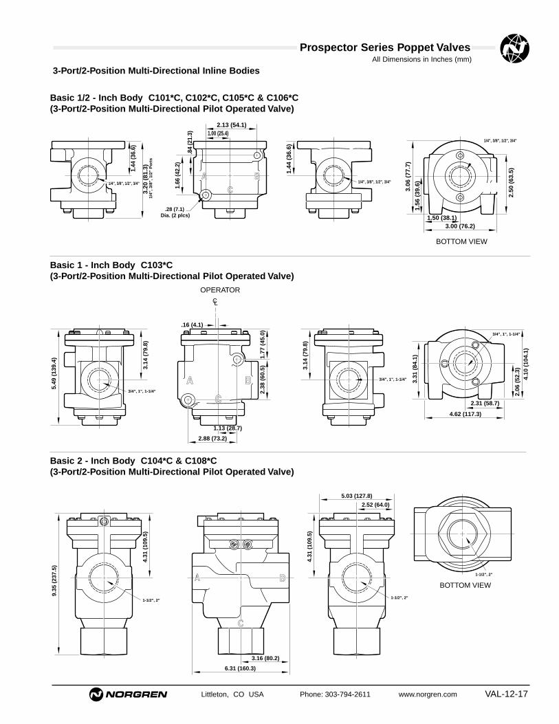
All Dimensions in Inches (mm)
Littleton, CO USA Phone: 303-794-2611 www.norgren.com VAL-12-17
Prospector Series Poppet Valves
Basic 1/2 - Inch Body C101*C, C102*C, C105*C & C106*C(3-Port/2-Position Multi-Directional Pilot Operated Valve)
A
C
B
1.00 (25.4)
.28 (7.1) Dia. (2 plcs)
2.13 (54.1)1.
44 (3
6.6)
3.20
(81
.3)
1/4
", 3
/8",
1/2
" P
ort
s
1.66
(42.
2)
.84
(21.
3)
1.50 (38.1)3.00 (76.2)
3.06
(77
.7)
1.56
(39
.6)
2.50
(63
.5)
1.44
(36
.6)
1/4", 3/8", 1/2", 3/4" 1/4", 3/8", 1/2", 3/4"
1/4", 3/8", 1/2", 3/4"
Basic 1 - Inch Body C103*C(3-Port/2-Position Multi-Directional Pilot Operated Valve)
Basic 2 - Inch Body C104*C & C108*C(3-Port/2-Position Multi-Directional Pilot Operated Valve)
3-Port/2-Position Multi-Directional Inline Bodies
2.88 (73.2)
3.14
(79
.8)
5.49
(13
9.4)
1.77
(45
.0)
3.14
(79
.8)
2.38
(60
.5)
.16 (4.1)
4.62 (117.3)
2.31 (58.7)
3.31
(84
.1)
4.10
(10
4.1)
2.06
(52
.3)
3/4", 1", 1-1/4"
1.13 (28.7)
3/4", 1", 1-1/4"
3/4", 1", 1-1/4"
6.31 (160.3)
3.16 (80.2)
9.35
(23
7.5)
4.31
(10
9.5)
4.31
(10
9.5)
5.03 (127.8)
2.52 (64.0)
1-1/2", 2"
1-1/2", 2"1-1/2", 2"
BOTTOM VIEW
BOTTOM VIEW
OPERATOR

Prospector Series Poppet ValvesAll Dimensions in Inches (mm)
VAL-12-18 Littleton, CO USA Phone: 303-794-2611 www.norgren.com
4-Port/2-Position Inline Bodies
Basic 1/4 - Inch Body F101*C(4-Port/2-Position Pilot Operated Valve)
CYL 2CYL 1 IN
EX
1.75 (44.5)
.69 (17.5)
3.13
(79
.5)
1.56
(39
.6)
3.00 (76.2)
1.50 (38.1)
1.22
(31
.1)
.66 (16.8) .84 (21.3)
1.15
(29
.1)
1.84
(46
.7)
.46 (11.7)
2.73
(69
.3)
1/4", 3/8"
.59
(15.
0)
1/4", 3/8"
3/8", 3/8"
Basic 1/2 - Inch Body F102*C(4-Port/2-Position Pilot Operated Valve)
CYL 2CYL 1 IN
EX
1.50 (38.1)
3.00 (76.2)
3.75 (95.3)2.00 (50.8)
A
1.69
(42
.9)
1.75 (44.5)
1.94
(49
.3)
.88
(22.
4)
.75
(19.
1)
2.75
(69
.9)
1.63 (41.4)
3.00 (76.2)
.34 (8.6) Dia. (2 plcs)
3.94
(10
0.1).3
8 (9
.7)
TY
P
3/8", 1/2", 3/4"1/2", 3/4", 3/4"
.88 (22.4)
3/8", 1/2", 3/4"
Basic 1 - Inch Body F103*C(4-Port/2-Position Pilot Operated Valve)
CYL 2CYL 1
IN
EXH
2.25 (57.2)
4.00 (101.6)
4.50 (114.3)
2.50
(63
.5)
.38
(9.7
) T
YP
5.00
(12
7.0)
1.25 (31.8)2.50 (63.5)
3.49
(88
.6)
6.23
(15
8.2)
1.75 (44.5)
3.50 (88.9)
1.44
(36
.6)
.41 (10.4) Dia. (2 plcs)
3.49
(88
.6)
2.24
(56
.9)
2.50
(63
.5)
3/4", 1", 1-1/4"3/4", 1", 1-1/4"1", 1-1/4", 1-1/4"
TOP VIEW
TOP VIEW

All Dimensions in Inches (mm)
Littleton, CO USA Phone: 303-794-2611 www.norgren.com VAL-12-19
Prospector Series Poppet Valves
Basic 1/2 - Inch Body F2214C(4-Port/2-Position Pilot Operated Valve)
4-Port/2-Position Subbase Bodies
EXH IN
CYL 1CYL 2
3.94 (100.1)
1.56 (39.6) 1.44 (36.6)
.25 (6.4) TYP
4.04
(10
2.6)
3.50
(88
.9)
1.75
(44
.5)
.27 (6.9) TYP
1.53
(38
.9)
3.03
(77
.0)
.53 (13.5)
4.95 (125.7)
1.31(33.3)1.63 (41.4)
1.56
(39
.6)
.81(20.6)
4.25 (107.9)
1.31(33.3) 1.63 (41.1) 1.31(33.3)
.34 (8.6) DIA (2 Plcs)
3.38
(85
.9)
4.20
(10
6.7)
.63
(16.
0) T
YP
.41
(10.
4)T
YP
.28 (7.1) DIA (6 plcs)
.81
(20.
6)
1/2", 3/4"
.35 (8.9) TYP
3/4", 3/4"1/2", 1/2"
Basic 1- Inch Body F2226C(4-Port/2-Position Pilot Operated Valve)
VALVE BODY SUBBASE
EXH IN
CYL 1CYL 2
6.23 (158.2)
2.00 (50.8) 2.31(58.7)
.34 (8.6) TYP
6.09
(15
4.7)
5.25
(13
3.4)
2.63
(66
.7)
.42(10.7) TYP
3.59
(91
.2)
.53(13.5) 1.84
(46
.7)
6.75 (171.5)
1.5(38.1)3.00 (76.2)
2.39
(60
.7)
1.06 (26.9)
6.00 (152.4)
1.50 (38.1) 1.50 (38.1)3.00 (76.2)
.41 (10.4) DIA (4 Plcs)
5.25
(13
3.4)
6.06
(15
3.9)
.34 (8.6) DIA (6 Plcs)
.38 (9.7) TYP
1.06
(26
.9)
.50
(12.
7)
.41
(10.
4) T
YP
1-1/4", 1"
1"
SUBBASEVALVE BODY

Prospector Series Poppet ValvesAll Dimensions in Inches (mm)
VAL-12-20 Littleton, CO USA Phone: 303-794-2611 www.norgren.com
Valve Body Operator with Standard Cable Grip Connector
* Gasket 0.03 (0.8) thick included in dimensions.
CC CE, CF, CY
Optional C Series
Conduit HousingC0, C1
3.00 (76) Dia.
3.30
(84
)*
Exhaust Diffuser
Manual Override
1/8" NPT ExternalPilot Port
*Gasket 0.03 (0.8) thick included in dimensions
3.00 (76) Dia.
2.93 (74)
3.18
(81
)*
Manual Override
1/8" - 27 NPT External Pilot Port
1/8" Solenoid Exhaust
1.29
(33
)
4.41 (112)
0.79
(20
) 1.97 (50)
1.59 (40.4)
Conduit Port 1/2" NPT
.32 (7.9)
Manual Override Locking
External Pilot Port 1/8" NPTF
3.00
(76
.2)
2.06
(52
.3)
3.09
(78
.5)*
.34 (8.6)
Optional P Series
.94
(23.
9)
3.00 (76.2) Dia.
External Pilot Port 1/8" NPTF
.62
(15.
7)
Aux. Outlet - 1/8" NPTF (Can be used for operating additional remote valve.)
1.87
(47
.5)
4.03
(10
2.4)
AC
Op
er.
.36 (9.1)
Conduit Port1/2" NPSM
Exhaust Port1/8" NPTF
(Do Not Restrict)
P1

All Dimensions in Inches (mm)
Littleton, CO USA Phone: 303-794-2611 www.norgren.com VAL-12-21
Prospector Series Poppet Valves
Valve Body Operator Dimensions with Optional X Series - Hazardous Location
X1
1.66 (42.2)
Conduit Port1/2" NPT
3.00
(76
.2)
.31 (7.9)Manual Override
- Locking
External Pilot Port1/8" NPTF
Exhaust Port1/4" NPT
4.22
(10
7.2)
2.36
(59
.9)
.34
(8.6
)*
Solenoid housings can be rotated 360°
* Gasket 0.03 (0.8) thick included in dimensions.

VAL-12-22 Littleton, CO USA Phone: 303-794-2611 www.norgren.com
Poppet Valves
● High flow - Cv of 1.2 to 49.5● Durable, robust construction● Two mounting styles: inline or subbase● 1/4" to 2" ports (BSPP, PTF, or ISO Rc threads)● Wide range of Air Pilot Operators available● Four functional types: available in 2/2, 3/2, 3/2
multi-directional and 4/2 configurations
1/4" to 2" Air Pilot Actuated 2/2, 3/2, & 4/2 Inline and Subbase Valves
Technical Data
Medium:Filtered and lubricated or non-lubricated compressed air or vacuum.
Operation:Poppet valve air pilot actuated.
Mounting:Through-holes in valve body and subbase.
Port Size:1/4" to 2" PTF, BSPP, or ISO Rc.
Operating Pressure:300 psig (Maximum 20.7 bar). For details see overleaf.
Flow Characteristics:Basic Size Function Cv* l/min1/4" 3/2 & 4/2 1.2 - 1.8 984 - 2,4351/2" 2/2, 3/2 & 4/2 3.2 - 5.8 3,398 - 6,2301" 2/2, 3/2 & 4/2 10.3 - 17.7 4,474 - 15,3482" 2/2 & 3/2 39.6 - 49.5 38,228 - 54,085*See VAL-12-58 for additional flow information.
Operating Temperature:-20°F to 175°F** (-29°C to 79°C)**Consult Technical Service for use below 35°F (+2°C).
Materials:Body: Aluminum alloy body, piston, poppets and subbase.Operators: Zinc or aluminum air pilot operators.Elastomers: Nitrile rubber seals. (Fluorocarbon seals areoptional, contact Technical Services.)
Ordering InformationTo order standard poppet valves with air pilotoperators, quote model number from tablesoverleaf, i.e. order D1024C-00-A1 for a 3-port,2-position, normally closed, Air Pilot OperatedSpring Return model.
3-Port/2-Position Multi-Directional
3-Port/2-Position
4-Port/2-Position 3-WayTwin Normally Closed
4-Port/2-Position4-Way
2-Port/2-Position
IN
OUTEXH
This example shows a 3-way normally closed valve.
OUTB
AIN
Normally OpenOUT
B
AIN
Normally Closed
EXH IN
OUTNormally Closed
EXH IN
OUTNormally Open
OUT2 OUT1
AIN
B C
Distributor
CYL 1IN
EXH CYL2
IN2 IN1
OUTA
B C
Selector
EXH IN
OUTA
C B
Normally Closed
EXH IN
OUTA
B C
Normally Open
CYL2 CYL1
IN EXH

Littleton, CO USA Phone: 303-794-2611 www.norgren.com VAL-12-23
Prospector Series Poppet Valves
Symbol Basic Port Model Operating Pilot Weight Repair Kit§Size Size Pressure Pressure lbs.(kg)
psig (bar) psig (bar)
1/4" B1012C-00-A10 - 300 30 -300 1.51
53474-03(0 - 20.7) (2.1 - 20.7) (0.69)
3/8" B1013C-00-A10 - 300 30 -300 1.51
53474-03(0 - 20.7) (2.1 - 20.7) (0.69)
1/2"1/2" B1014C-00-A1
0 - 300 30 -300 1.5153474-03
(0 - 20.7) (2.1 - 20.7) (0.69)
3/4" B1015C-00-A10 - 300 30 -300 1.51
53474-03(0 - 20.7) (2.1 - 20.7) (0.69)
3/4" B1025C-00-A10 - 300 30 -300 3.69
53475-01(0 - 20.7) (2.1 - 20.7) (1.68)
1"1" B1026C-00-A1
0 - 300 30 -300 3.6953475-01
(0 - 20.7) (2.1 - 20.7) (1.68)
1-1/4" B1027C-00-A10 - 300 30 -300 3.69
53475-01(0 - 20.7) (2.1 - 20.7) (1.68)
Air Pilot Operated Spring Return Inline and Subbase Valves
Below listed operators are single air operators with spring returns.
2-Port/2-Position (2 way) Inline, Normally Closed
§ Repair Kit: Kit contains all elastomers necessary to service one valve body.Note: Pilot supply pressure must be equal to or greater than the operating pressure.
Symbol Basic Port Model Operating Pilot Weight Repair Kit§Size Size Pressure Pressure lbs.(kg)
psig (bar) psig (bar)
1/4" A1012C-00-A10 - 300 30 -300 1.51
53474-03(0 - 20.7) (2.1 - 20.7) (0.69)
3/8" A1013C-00-A10 - 300 30 -300 1.51
53474-03(0 - 20.7) (2.1 - 20.7) (0.69)
1/2"1/2" A1014C-00-A1
0 - 300 30 -300 1.5153474-03
(0 - 20.7) (2.1 - 20.7) (0.69)
3/4" A1015C-00-A10 - 300 30 -300 1.51
53474-03(0 - 20.7) (2.1 - 20.7) (0.69)
3/4" A1025C-00-A10 - 300 30 -300 3.69
53475-01(0 - 20.7) (2.1 - 20.7) (1.68)
1"1" A1026C-00-A1
0 - 300 30 -300 3.6953475-01
(0 - 20.7) (2.1 - 20.7) (1.68)
1-1/4" A1027C-00-A10 - 300 30 -300 3.69
53475-01(0 - 20.7) (2.1 - 20.7) (1.68)
1-1/2" A1038C-00-A10 - 300 30 -300 8.05
53822-01
2"(0 - 20.7) (2.1 - 20.7) (3.65)
2" A1039C-00-A10 - 300 30 -300 8.05
53822-01(0 - 20.7) (2.1 - 20.7) (3.65)
2-Port/2-Position (2 way) Inline, Normally Open
OUTB
AIN
OUTB
AIN

Prospector Series Poppet Valves
VAL-12-24 Littleton, CO USA Phone: 303-794-2611 www.norgren.com
Below listed operators are single air operators with spring returns.
3-Port/2-Position (3 way) Inline, Normally Closed
3-Port/2-Position (3 way) Inline, Normally Open
Symbol Basic Port Model Operating Pilot Weight Repair Kit§Size Size Pressure Pressure lbs.(kg)
psig (bar) psig (bar)
1/4" D1012H-00-A10 - 300 30 - 300 1.20
53474-051/4"
(0 - 20.7) (2.1 - 20.7) (0.55)
3/8" D1013H-00-A10 - 300 30 - 300 1.20
53474-05(0 - 20.7) (2.1 - 20.7) (0.55)
1/4" D1022C-00-A10 - 300 30 - 300 1.79
53474-03(0 - 20.7) (2.1 - 20.7) (0.81)
3/8" D1023C-00-A10 - 300 30 - 300 1.79
53474-03(0 - 20.7) (2.1 - 20.7) (0.81)
1/2"1/2" D1024C-00-A1
0 - 300 30 - 300 1.7953475-03
(0 - 20.7) (2.1 - 20.7) (0.81)
3/4" D1025C-00-A10 - 300 30 - 300 1.79
53475-03(0 - 20.7) (2.1 - 20.7) (0.81)
3/4" D1035C-00-A10 - 300 30 - 300 3.78
53475-01(0 - 20.7) (2.1 - 20.7) (1.72)
1" 1" D1036C-00-A10 - 300 30 - 300 3.78
53475-01(0 - 20.7) (2.1 - 20.7) (1.72)
1-1/4" D1047C-00-A10 - 300 30 - 300 3.78
53475-01(0 - 20.7) (2.1 - 20.7) (1.72)
Symbol Basic Port Model Operating Pilot Weight Repair Kit§Size Size Pressure Pressure lbs.(kg)
psig (bar) psig (bar)
1/4" E1012H-00-A10 - 300 30 - 300 1.20
53473-05(0 - 20.7) (2.1 - 20.7) (0.55)
1/4"3/8" E1013H-00-A1
0 - 300 30 - 300 1.2053473-05
(0 - 20.7) (2.1 - 20.7) (0.55)
1/4" E1022C-00-A10 - 300 30 - 300 1.79
53474-03(0 - 20.7) (2.1 - 20.7) (0.81)
3/8" E1023C-00-A10 - 300 30 - 300 1.79
53474-031/2"
(0 - 20.7) (2.1 - 20.7) (0.81)
1/2" E1024C-00-A10 - 300 30 - 300 1.79
53474-03(0 - 20.7) (2.1 - 20.7) (0.81)
3/4" E1025C-00-A10 - 300 30 - 300 1.79
53474-03(0 - 20.7) (2.1 - 20.7) (0.81)
3/4" E1035C-00-A10 - 300 30 - 300 3.78
53475-01(0 - 20.7) (2.1 - 20.7) (1.72)
1" 1" E1036C-00-A10 - 300 30 - 300 3.78
53475-01(0 - 20.7) (2.1 - 20.7) (1.72)
1-1/4" E1047C-00-A10 - 300 30 - 300 3.78
53475-01(0 - 20.7) (2.1 - 20.7) (1.72)
§ Repair Kit: Kit contains all elastomers necessary to service one valve body.Note: Pilot supply pressure must be equal to or greater than the operating pressure.
EXH IN
OUT
EXH IN
OUTNormally Open

Littleton, CO USA Phone: 303-794-2611 www.norgren.com VAL-12-25
Prospector Series Poppet Valves
Below listed operators are single air operators with spring returns.
3-Port/2-Position (3 way) Multi-Directional Inline
§ Repair Kit: Kit contains all elastomers necessary to service one valve body.Note: Pilot supply pressure must be equal to or greater than the operating pressure.
Symbol Basic Port Model Operating Pilot Weight Repair Kit§Size Size Pressure Pressure lbs.(kg)
psig (bar) psig (bar)
1/4" C1012C-00-A10 - 300 30 - 300 1.41
53474-03(0 - 20.7) (2.1 - 20.7) (0.64)
3/8" C1013C-00-A10 - 300 30 - 300 1.41
53474-031/2"
(0 - 20.7) (2.1 - 20.7) (0.64)
1/2" C1014C-00-A10 - 300 30 - 300 1.41
53474-03(0 - 20.7) (2.1 - 20.7) (0.64)
3/4" C1025C-00-A10 - 300 30 - 300 1.41
53474-03(0 - 20.7) (2.1 - 20.7) (0.64)
3/4" C1035C-00-A10 - 300 30 - 300 3.94
53475-01(0 - 20.7) (2.1 - 20.7) (1.79)
1" 1" C1036C-00-A10 - 300 30 - 300 3.94
53475-01(0 - 20.7) (2.1 - 20.7) (1.79)
1-1/4" C1037C-00-A10 - 300 30 - 300 3.94
53475-01(0 - 20.7) (2.1 - 20.7) (1.79)
1-1/2" C1048C-00-A10 - 300 30 - 300 8.75
53822-012"
(0 - 20.7) (2.1 - 20.7) (3.97)
2" C1049C-00-A10 - 300 30 - 300 8.75
53822-01(0 - 20.7) (2.1 - 20.7) (3.97)
4-Port/2-Position (3 way twin) Inline
Symbol Basic Port Model Operating Pilot Weight Repair Kit§Size Size Pressure Pressure lbs.(kg)
psig (bar) psig (bar)
3/8" G1023B-00-A40 - 300 30 - 300 2.25
53474-03(0 - 20.7) (2.1 - 20.7) (1.02)
1/2" 1/2" G1024B-00-A40 - 300 30 - 300 2.25
53474-03(0 - 20.7) (2.1 - 20.7) (1.02)
3/4" G1025B-00-A40 - 300 30 - 300 2.25
53474-03(0 - 20.7) (2.1 - 20.7) (1.02)
3/4" G1035B-00-A40 - 300 30 - 300 4.96
53474-03(0 - 20.7) (2.1 - 20.7) (2.25)
1" G1036B-00-A40 - 300 30 - 300 4.96
53475-011"(0 - 20.7) (2.1 - 20.7) (2.25)
1-1/4" G1037B-00-A40 - 300 30 - 300 4.96
53475-01(0 - 20.7) (2.1 - 20.7) (2.25)
CYL 1IN
EXH CYL2
These modelsmay be used asDistributor,Selector,Normally Openor NormallyClosed.

Prospector Series Poppet Valves
VAL-12-26 Littleton, CO USA Phone: 303-794-2611 www.norgren.com
Symbol Basic Port Model Operating Pilot Weight Repair Kit§Size Size Pressure Pressure lbs.(kg)
psig (bar) psig (bar)
1/4" F1012C-00-A10 - 300 30 - 300 1.81
53473-051/4"
(0 - 20.7) (2.1 - 20.7) (0.82)
3/8" F1013C-00-A10 - 300 30 - 300 1.81
53473-05(0 - 20.7) (2.1 - 20.7) (.82)
3/8" F1023C-00-A10 - 300 30 - 300 2.30
53474-061/2"
(0 - 20.7) (2.1 - 20.7) (1.04)
1/2" F1024C-00-A10 - 300 30 - 300 2.30
53474-06(0 - 20.7) (2.1 - 20.7) (1.04)
3/4" F1025C-00-A10 - 300 30 - 300 2.30
53474-06(0 - 20.7) (2.1 - 20.7) (1.79)
3/4" F1035C-00-A10 - 300 30 - 300 5.42
53475-061"
(0 - 20.7) (2.1 - 20.7) (2.46)
1" F1036C-00-A10 - 300 30 - 300 5.42
53475-06(0 - 20.7) (2.1 - 20.7) (2.46)
1-1/4" F1037C-00-A10 - 300 30 - 300 5.42
53475-06(0 - 20.7) (2.1 - 20.7) (2.46)
* Thread: Insert A for Inline BSPP; 1 for Inline PTF; or B for Inline ISO Rc; 4 for Subbase valve with subbase, BSPP; 5 for Subbase valve without subbase, BSPP; 2 for Subbase valvewith subbase, PTF; 3 for Subbase valve without subbase, PTF; 6 for Subbase valve with subbase, ISO Rc; or 7 for Subbase valve without subbase, ISO Rc.
§ Repair Kit: Kit contains all elastomers necessary to service one valve body.Note: Pilot supply pressure must be equal to or greater than the operating pressure.
Below listed operators are single air operators with spring returns.
4-Port/2-Position (4 way) Inline
CYL2 CYL1
IN EXH
Symbol Basic Port Model Operating Pilot Weight Repair Kit§Size Size Pressure Pressure lbs.(kg)
psig (bar) psig (bar)
1/2" 1/2" F2214C-00-A10 - 300 30 - 300 3.96
53474-06(0 - 20.7) (2.1 - 20.7) (1.80)
1" 1" F2226C-00-A10 - 300 30 - 300 9.62
53475-06(0 - 20.7) (2.1 - 20.7) (4.37)
4-Port/2-Position (4 way) Subbase
CYL2 CYL1
IN EXH

Littleton, CO USA Phone: 303-794-2611 www.norgren.com VAL-12-27
Prospector Series Poppet Valves
Air Pilot Operated Inline & Subbase Valves
Options InformationFor optional features, note the valve model number that comes closest to the desired valve from the preceding order table. Change the model
number as shown in the following diagram to obtain the desired option. For example: the ordering table on VAL-12-21 shows D1022C-00-A1, a
3-port/2-position single air pilot operated valve with spring return. To use this valve with a twin operator, change the last two digits to A4, as shown
below.
D 1 0 2 2 C 0 0 A 1
Position in Model Number
1 2 3 4 5 6 7 8 9 10
Operator Options Weight lbs. (kg)
A A A1 Operator with 0.29 (0.13)BSPP Threads
A 6 Momentary Signal 0.38 (0.17)Operator (PTF Threads)†
AF Momentary Signal 0.38 (0.17)Operator (BSPP Threads)†*
A4 Twin Operator 0.59 (0.27)(PTF Threads Only)§§
7 Indicator Pin (Basic 1/2" valve)**
8 Indicator Pin (Basic 1" valve)**
F Bleed Operation††
K Momentary Signal Operation†
J Vacuum Service§
† MOMENTARY SIGNAL OPERATOR : Used when it is desirableto control the valve with 2 alternately appliedmomentary signals of 0.2 second minimum duration(first signal shifts and hold the poppet; the secondallows the poppet to return to its normal position).Available only on 3-port/2-position normally closedvalves and on 4-port/2 position (4-way) valves. Be sureto change the 6th, 9th and 10th positions of the modelnumber.
§§TWIN OPERATOR : Allows independent operation of eachvalve element. Available only on 4-port/2-position (4-way) valves.
* REPAIR KIT : Available for A6 operator. Kit contains allelastomers necessary to service one operator body. Toorder, request: 53476-01.
To calculate the weight of a valve and optional operator take the weight given for the relevant valve from the ordering tables, subtract either 0.29 lbs (0.13 kg) for an A1 operator and add the weight given above for the appropriate optional operator.
For example: For D1022C-00-A1 has a listed weight of 1.79 lbs (0.81 kg ). To convert this to a Momentary Signal Operator, i.e. D1022C-00-A6 ➔ 0.81 - 0.13 + 0.17 = 0.85 kg (1.87 lbs.)
Example model number is a 3-port/2-position (3-way) normallyclosed valve with a single air operator, and spring return.
Vacuum Service§
For on-off application of vacuum, use anormally closed 2-port/2-position (2-way) valve.When the valve is actuated, vacuum will beapplied to the outlet port.
For selecting alternately between vacuum andpressure, use a normally open 3-port/2-position(3-way) valve. Connect the vacuum to the exhaustport and pressure to the inlet port. When thevalve is actuated, vacuum will be applied to theoutlet port.
For selecting alternately between vacuum andvent, use a normally open 3-port/2-position (3-way) valve. Connect the vacuum to the exhaustport and vent the inlet port. When the valve isactuated, vacuum will be applied to the outletport.
In addition, a 4-port/2-position (4-way) valvecan be connected the same way as 3-port/2-position (3-way) valves for selecting alternatelybetween vacuum and pressure or vacuum andvent. That is, connect the vacuum to the exhaustport and pressure or vent to the inlet port. Whenthe valve is actuated, the cylinder ports (outlets)will be alternately switched between vacuum andpressure or vacuum and vent.

Prospector Series Poppet ValvesAll Dimensions in Inches (mm)
VAL-12-28 Littleton, CO USA Phone: 303-794-2611 www.norgren.com
Valve Body Dimensions – 2-Port/2-Position Inline Bodies
Basic 1/2-Inch Body A101*C & B101*C(2-Port/2 Position Pilot Operated Valve)
Basic 1-Inch Body A102*C & B102*C(2-Port/2 Position Pilot Operated Valve)
Basic 2-Inch Body A103*C & C104*C(2-Port/2 Position Pilot Operated Valve)
2.13 (54.1)1.00 (25.4)
.28 (7.1) Dia. (2 plcs)
.84
(21.
3)
1.66
(42
.2)
2.90
(73
.7)
1.44
(36
.6)
1.44
(36
.6)
3.00 (76.2)1.50 (38.1)
1.56
(39
.6)
2.50
(63
.5)
3.06
(77
.7)
EXH PORTINLET PORT
2.88 (73.2)1.13 (28.7)
3.14
(79
.8)
5.20
(13
2.1) 1.
89 (
48.0
)
3.14
(79
.8)
2.38
(60
.5)
.16 (4.1)
4.62 (117.3)
2.31 (58.7)3.
31 (
84.1
)
4.10
(10
4.1)
2.06
(52
.3)
INLET PORT
EXHPORT
OPERATOR
6.31 (160.3)
3.16 (80.2)
8.05
(20
4.5)
4.31
(10
9.5)
4.31
(10
9.5)
5.03 (127.8)
2.52 (64.0)
INLET PORT
EXHPORT

All Dimensions in Inches (mm)
Littleton, CO USA Phone: 303-794-2611 www.norgren.com VAL-12-29
Prospector Series Poppet Valves
3-Port/2-Position Inline Bodies
Basic 1/4-Inch Body D101*B & E101*B (3-Port/2-Position Pilot Operated Valve)
Basic 1/2 - Inch Body D102*C & E102*C (3-Port/2-Position Pilot Operated Valve)
Basic 1 - Inch Body D103*C, D104*C, E103*C & E104*C (3-Port/2-Position Pilot Operated Valve)
3.06 (77.7)
2.50 (63.5)
1.13
(28.
7)
3/8", 3/8"
.53 (13.5)
2.69
(68
.3)
.88
(22.
4)
.53 (13.5)
1.56
(39.
6)
3.00
(76
.2)
3.56
(90
.4)
.28 (7.1) TYP
5.6 (.22) Dia. (2 Plcs)
1/4", 3/8"1/4", 3/8"
EXH
OUT
IN
1.50 (38.1)
3.00 (76.2)
3.06
(77
.7)
1.56
(39
.6)
3/8", 1/2", 3/4", 3/4"1/4", 3/8", 1/2", 3/4"
3.89
(98
.8(
(Std
)4.
15 (
105.
4) (
Ind
icat
or)
1.03 (26.2)1.
03 (
26.2
)
1.94
(49
.3)
2.75
(69
.8)
2.31 (58.7)2.00 (50.8)
1.00 (25.4)
.28
(7.1
) D
ia.(
1 P
lcs)
.87 (22.1)
1/4", 3/8", 1/2", 3/4"
IN
OUT
EXH
2.00 (50.8)
4.00 (101.6)
4.06
(10
3.1)
2.06
(52
.3)
3/4", 1", 1-1/4" 1", 1-1/4", 1-1/4"
2.75 (69.9)1.38 (34.9)3.13 (79.5)
16.6
(15
6.6)
(S
td)
6.20
(15
7.5)
(In
dic
ato
r)
1.90
(48
.3)
2.02
(51
.3)
3.40
(86
.4)
1.25
(31
.8)
4.65
(11
8.1)
.41
(10.
4) D
ia. (
2 P
lcs)
3/4", 1", 1-1/4"

Prospector Series Poppet ValvesAll Dimensions in Inches (mm)
VAL-12-30 Littleton, CO USA Phone: 303-794-2611 www.norgren.com
3-Port/2-Position Multi-Directional Inline Bodies
Basic 1/2 - Inch Body C101*C, C102*C, C105*C & C106*C(3-Port/2-Position Multi-Directional Operated Valve)
Basic 1 - Inch Body C103*C & C103*H(3-Port/2-Position Multi-Directional Operated Valve)
Basic 2 - Inch Body C104*C, C108*C & C104*H(3-Port/2-Position Multi-Directional Operated Valve)
A
C
B
1.00 (25.4)
.28 (7.1) Dia. (2 plcs)
2.13 (54.1)1.
44 (3
6.6)
3.20
(81
.3)
1/4
", 3
/8",
1/2
" P
ort
s
1.66
(42.
2)
.84
(21.
3)
1.50 (38.1)3.00 (76.2)
3.06
(77
.7)
1.56
(39
.6)
2.50
(63
.5)
1.44
(36
.6)
1/4", 3/8", 1/2", 3/4" 1/4", 3/8", 1/2", 3/4"
1/4", 3/8", 1/2", 3/4"
2.88 (73.2)
3.14
(79
.8)
5.49
(13
9.4)
1.77
(45
.0)
3.14
(79
.8)
2.38
(60
.5)
.16 (4.1)
4.62 (117.3)
2.31 (58.7)
3.31
(84
.1)
4.10
(10
4.1)
2.06
(52
.3)
3/4", 1", 1-1/4"
1.13 (28.7)
3/4", 1", 1-1/4"
3/4", 1", 1-1/4"
6.31 (160.3)
3.16 (80.2)
9.35
(23
7.5)
4.31
(10
9.5)
4.31
(10
9.5)
5.03 (127.8)
2.52 (64.0)
1-1/2", 2"
1-1/2", 2"1-1/2", 2"
OPERATOR

All Dimensions in Inches (mm)
Littleton, CO USA Phone: 303-794-2611 www.norgren.com VAL-12-31
Prospector Series Poppet Valves
Valve Body Dimensions – 4-Port/2-Position Inline Bodies
Basic 1/4 - Inch Body F101*C (4-Port/2-Position Pilot Operated Valve)
Basic 1/2 - Inch Body F102*C (4-Port/2-Position Pilot Operated Valve)
Basic 1 - Inch Body F103*C (4-Port/2-Position Pilot Operated Valve)
CYL 2CYL 1 IN
EX
1.75 (44.5)
.69 (17.5)
3.13
(79
.5)
1.56
(39
.6)
3.00 (76.2)
1.50 (38.1)
1.22
(31
.1)
.66 (16.8) .84 (21.3)
1.15
(29
.1)
1.84
(46
.7)
.46 (11.7)
2.73
(69
.3)
1/4", 3/8"
.59
(15.
0)
1/4", 3/8"
3/8", 3/8"
CYL 2CYL 1 IN
EX
1.50 (38.1)
3.00 (76.2)
3.75 (95.3)2.00 (50.8)
A
1.69
(42
.9)
1.75 (44.5)
1.94
(49
.3)
.88
(22.
4)
.75
(19.
1)
2.75
(69
.9)
1.63 (41.4)
3.00 (76.2)
.34 (8.6) Dia. (2 plcs)
3.94
(10
0.1).3
8 (9
.7)
TY
P
3/8", 1/2", 3/4"1/2", 3/4", 3/4"
.88 (22.4)
3/8", 1/2", 3/4"
CYL 2CYL 1
IN
EXH
2.25 (57.2)
4.00 (101.6)
4.50 (114.3)
2.50
(63
.5)
.38
(9.7
) T
YP
5.00
(12
7.0)
1.25 (31.8)2.50 (63.5)
3.49
(88
.6)
6.2
3 (1
58.2
)
44.5 (1.75)
88.9 (3.50)
1.44
(36
.6)
.41 (10.4) Dia. (2 plcs)
3.49
(88
.6)
2.24
(56
.9)
2.50
(63
.5)
3/4", 1", 1-1/4"3/4", 1", 1-1/4"1", 1-1/4", 1-1/4"
TOP VIEW
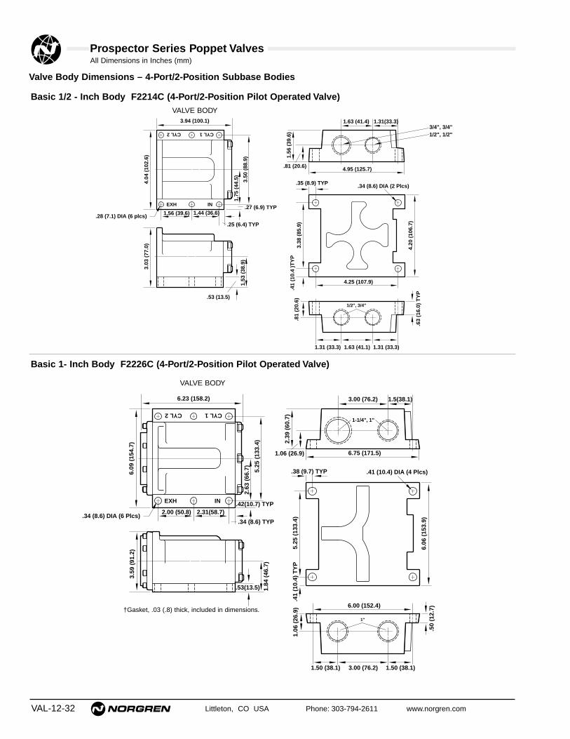
Prospector Series Poppet ValvesAll Dimensions in Inches (mm)
VAL-12-32 Littleton, CO USA Phone: 303-794-2611 www.norgren.com
Valve Body Dimensions – 4-Port/2-Position Subbase Bodies
Basic 1/2 - Inch Body F2214C (4-Port/2-Position Pilot Operated Valve)
Basic 1- Inch Body F2226C (4-Port/2-Position Pilot Operated Valve)
EXH IN
CYL 1CYL 2
3.94 (100.1)
1.56 (39.6) 1.44 (36.6)
.25 (6.4) TYP
4.04
(10
2.6)
3.50
(88
.9)
1.75
(44
.5)
.27 (6.9) TYP
1.53
(38
.9)
3.03
(77
.0)
.53 (13.5)
4.95 (125.7)
1.31(33.3)1.63 (41.4)
1.56
(39
.6)
.81 (20.6)
4.25 (107.9)
1.31 (33.3) 1.63 (41.1) 1.31 (33.3)
.34 (8.6) DIA (2 Plcs)
3.38
(85
.9)
4.20
(10
6.7)
.63
(16.
0) T
YP
.41
(10.
4 )T
YP
.28 (7.1) DIA (6 plcs)
.81
(20.
6)
1/2", 3/4"
.35 (8.9) TYP
3/4", 3/4"1/2", 1/2"
VALVE BODY
EXH IN
CYL 1CYL 2
6.23 (158.2)
2.00 (50.8) 2.31(58.7)
.34 (8.6) TYP
6.09
(15
4.7)
5.25
(13
3.4)
2.63
(66
.7)
.42(10.7) TYP
3.59
(91
.2)
.53(13.5) 1.84
(46
.7)
6.75 (171.5)
1.5(38.1)3.00 (76.2)
2.39
(60
.7)
1.06 (26.9)
6.00 (152.4)
1.50 (38.1) 1.50 (38.1)3.00 (76.2)
.41 (10.4) DIA (4 Plcs)
5.25
(13
3.4)
6.06
(15
3.9)
.34 (8.6) DIA (6 Plcs)
.38 (9.7) TYP
1.06
(26
.9)
.50
(12.
7)
.41
(10.
4) T
YP
1-1/4", 1"
1"
†Gasket, .03 (.8) thick, included in dimensions.
VALVE BODY

All Dimensions in Inches (mm)
Littleton, CO USA Phone: 303-794-2611 www.norgren.com VAL-12-33
Prospector Series Poppet Valves
Air Pilot Operator Dimensions
A1 & AA Single
1/4"0.
67 (
17)*
3.00
(76
)
A4 Twin
18 (.69)
0.67
(17
)*
3.00
(76
)
1/4"
* Gasket, 0.03 (0.8) thick included in dimension.

VAL-12-34 Littleton, CO USA Phone: 303-794-2611 www.norgren.com
● High flow - Cv of 1.2 to 49.5
● Durable, robust construction
● Two mounting styles: inline or subbase
● 1/4" to 2" ports (PTF, BSPP, or ISO Rc threads)
● Wide range of Manual and Mechanical
Operators available
● Four functional types: available in 2/2, 3/2, 3/2
multi-directional and 4/2 configurations
1/4" to 2" Manual & Mechanical Actuated 2/2, 3/2, & 4/2 Inline and Subbase Valves
Technical Data
Medium:Filtered and lubricated or non-lubricated compressed air or vacuum.
Operation:Poppet valve manual and mechanical pilot actuated.
Mounting:Through-holes in valve body and subbase.
Port Size:1/4" to 2" PTF, BSPP, or ISO Rc.
Operating Pressure:Maximum 300 psig (20.7 bar). For details see overleaf.
Flow Characteristics:Basic Size Function Cv* l/min1/4" 3/2 & 4/2 1.2 - 1.8 984 - 2,4351/2" 2/2, 3/2 & 4/2 3.2 - 5.8 3,398 - 6,2301" 2/2, 3/2 & 4/2 10.3 - 17.7 4,474 - 15,3482" 2/2 & 3/2 39.6 - 49.5 38,228 - 54,085*See VAL-12-58 for additional flow information.
Operating Temperature:-20°F to 175°F** (-29°C to 79°C)**Consult Technical Service for use below 35°F (+2°C).
Materials:Body: Aluminum alloy body, piston, poppets and subbase.Operators: Aluminum manual and mechanical operators,stainless steel, acetal, steel.Elastomers: Nitrile rubber seals. (Fluorocarbon seals areoptional, contact Technical Services.)
Ordering InformationTo order standard poppet valves with manual/mechanical operators, quote model number fromtables overleaf, e.g. order D1024C-00-MB for a 3-port, 2-position, normally closed, Palm ButtonMechanically Operated Spring Return model.
M B - Palm Button
M C, M D - Lever
M J, M K - Roller
M M - Foot Pedal

Prospector Series Poppet Valves
Littleton, CO USA Phone: 303-794-2611 www.norgren.com VAL-12-35
Manual & Mechanical Operated Spring Return Inline and Subbase Valves
2-Port/2-Position (2 way) Inline, Normally ClosedBelow listed operators are palm button, spring return mechanical operators.
† External Pilot Supply : Pilot supply pressure must be equal to or greater than the operating pressure.§ Spares Kit: Kits contain all elastomers necessary to service one valve body.
Symbol Pilot Basic Port Model Operating Pilot Weight Repair Kit§Type Size Size Pressure Pressure lbs. (kg)
psig (bar) psig (bar)Internal
1/4" A1012C-00-MB30 - 300 30 - 300 2.10
53474-03Pilot (2.1 - 20.7) (2.1 - 20.7) (0.95)
3/8" A1013C-00-MB30 - 300 30 - 300 2.10
53474-03(2.1 - 20.7) (2.1 - 20.7) (0.95)
1/2"1/2" A1014C-00-MB
30 - 300 30 - 300 2.1053474-03
(2.1 - 20.7) (2.1 - 20.7) (0.95)
3/4" A1015C-00-MB30 - 300 30 - 300 2.10
53474-03 (2.1 - 20.7) (2.1 - 20.7) (0.95)
3/4" A1025C-00-MB30 - 300 30 - 300 4.27
53475-01(2.1 - 20.7) (2.1 - 20.7) (1.94)
1" A1026C-00-MB30 - 300 30 - 300 4.27
53475-01 1"(2.1 - 20.7) (2.1 - 20.7) (1.94)
1-1/4" A1027C-00-MB30 - 300 30 - 300 4.27
53475-01 (2.1 - 20.7) (2.1 - 20.7) (1.94)
1-1/2" A1038C-00-MB30 - 300 30 - 300 8.64
53822-01 (2.1 - 20.7) (2.1 - 20.7) (3.92)
2"2" A1039C-00-MB
30 - 300 30 - 300 8.6453822-01
(2.1 - 20.7) (2.1 - 20.7) (3.92)External
1/4" A1012H-00-MB0 - 300 30 - 300 2.10
53474-03Pilot (0 - 20.7) (2.1 - 20.7†) (0.95)
3/8" A1013H-00-MB0 - 300 30 - 300 2.10
53474-03(0 - 10.3) (2.1 - 20.7†) (0.95)
1/2"1/2" A1014H-00-MB
0 - 300 30 - 300 2.1053474-03
(0 - 10.3) (2.1 - 10.3†) (0.95)
3/4" A1015H-00-MB0 - 300 30 - 300 2.10
53474-03(0 - 10.3) (2.1 - 10.3†) (0.95)
3/4" A1025H-00-MB0 - 300 30 - 300 4.27
53475-01(0 - 10.3) (2.1 - 10.3†) (1.94)
1" A1026H-00-MB0 - 300 30 - 300 4.27
53475-011"(0 - 10.3) (2.1 - 10.3†) (1.94)
1-1/4" A1027H-00-MB0 - 300 30 - 300 4.27
53475-01(0 - 10.3) (2.1 - 10.3†) (1.94)
1-1/2" A1038H-00-MB0 - 300 30 - 300 8.64
53822-01(0 - 10.3) (2.1 - 10.3†) (3.92)
2"2" A1039H-00-MB
0 - 300 30 - 300 8.6453822-01
(0 - 10.3) (2.1 - 10.3†) (3.92)
OUTB
AIN
OUTB
AIN

Prospector Series Poppet Valves
VAL-12-36 Littleton, CO USA Phone: 303-794-2611 www.norgren.com
2-Port/2-Position (2 way) Inline, Normally OpenBelow listed operators are palm button, spring return mechanical operators.
Symbol Pilot Basic Port Model Operating Pilot Weight Repair Kit§Type Size Size Pressure Pressure lbs. (kg)
psig (bar) psig (bar)Internal
1/4" B1012C-00-MB30 - 300 30 - 300 2.10
53474-03 Pilot (2.1 - 20.7) (2.1 - 20.7) (0.95)
3/8" B1013C-00-MB30 - 300 30 - 300 2.10
53474-03 (2.1 - 20.7) (2.1 - 20.7) (0.95)
1/2"1/2" B1014C-00-MB
30 - 300 30 - 300 2.1053474-03
(2.1 - 20.7) (2.1 - 20.7) (0.95)
3/4" B1015C-00-MB30 - 300 30 - 300 2.10
53474-03 (2.1 - 20.7) (2.1 - 20.7) (0.95)
3/4" B1025C-00-MB30 - 300 30 - 300 4.27
53475-01 (2.1 - 20.7) (2.1 - 20.7) (1.94)
1" B1026C-00-MB30 - 300 30 - 300 4.27
53475-01 1"(2.1 - 20.7) (2.1 - 20.7) (1.94)
1-1/4" B1027C-00-MB30 - 300 30 - 300 4.27
53475-01 (2.1 - 20.7) (2.1 - 20.7) (1.94)
External1/4" B1012H-00-MB
0 - 300 30 - 300 2.1053474-03
Pilot (0 - 20.7) (2.1 - 20.7†) (0.95)
3/8" B1013H-00-MB0 - 300 30 - 300 2.10
53474-03 (0 - 20.7) (2.1 - 20.7†) (0.95)
1/2"1/2" B1014H-00-MB
0 - 300 30 - 300 2.1053474-03
(0 - 20.7) (2.1 - 10.3†) (0.95)
3/4" B1015H-00-MB0 - 300 30 - 300 2.10
53474-03 (0 - 20.7) (2.1 - 10.3†) (0.95)
3/4" B1025H-00-MB0 - 300 30 - 300 4.27
53475-01 (0 - 20.7) (2.1 - 10.3†) (1.94)
1" B1026H-00-MB0 - 300 30 - 300 4.27
53475-01 1"(0 - 20.7) (2.1 - 10.3†) (1.94)
1-1/4" B1027H-00-MB0 - 300 30 - 300 4.27
53475-01 (0 - 20.7) (2.1 - 10.3†) (1.94)
OUTB
AIN
OUTB
AIN
† External Pilot Supply: Pilot supply pressure must be equal to or greater than the operating pressure.§ Spares Kit: Kits contain all elastomers necessary to service one valve body.

Prospector Series Poppet Valves
Littleton, CO USA Phone: 303-794-2611 www.norgren.com VAL-12-37
Symbol Pilot Basic Port Model Operating Pilot Weight Repair Kit§Type Size Size Pressure Pressure lbs. (kg)
psig (bar) psig (bar)Internal
1/4" D1012B-00-MB30 - 300 30 - 300 1.79
53473-05Pilot
1/4"(2.1 - 20.7) (2.1 - 20.7) (0.81)
3/8" D1013B-00-MB30 - 300 30 - 300 1.79
53473-05(2.1 - 20.7) (2.1 - 20.7) (0.81)
1/4" D1022C-00-MB30 - 300 30 - 300 2.38
53474-03(2.1 - 20.7) (2.1 - 20.7) (1.08)
3/8" D1023C-00-MB30 - 300 30 - 300 2.38
53474-031/2"
(2.1 - 20.7) (2.1 - 20.7) (1.08)
1/2" D1024C-00-MB30 - 300 30 - 300 2.38
53474-03(2.1 - 20.7) (2.1 - 20.7) (1.08)
3/4" D1025C-00-MB30 - 300 30 - 300 2.38
53474-03(2.1 - 20.7) (2.1 - 20.7) (1.08)
3/4" D1035C-00-MB30 - 300 30 - 300 4.37
53475-01(2.1 - 20.7) (2.1 - 20.7) (1.99)
1" 1" D1036C-00-MB30 - 300 30 - 300 4.37
53475-01(2.1 - 20.7) (2.1 - 20.7) (1.99)
1-1/4" D1047C-00-MB30 - 300 30 - 300 4.37
53475-01(2.1 - 20.7) (2.1 - 20.7) (1.99)
External1/4" D1012H-00-MB
0 - 150 30 - 300 1.7953473-05
Pilot1/4"
(0 - 20.7) (2.1 - 20.7†) (0.81)
3/8" D1013H-00-MB0 - 300 30 - 300 1.79
53473-05(0 - 20.7) (2.1 - 20.7†) (0.81)
1/4" D1022H-00-MB0 - 300 30 - 300 2.38
53474-03(0 - 20.7) (2.1 - 20.7†) (1.08)
3/8" D1023H-00-MB0 - 300 30 - 300 2.38
53474-031/2"
(0 - 20.7) (2.1 - 20.7†) (1.08)
1/2" D1024H-00-MB0 - 300 30 - 300 2.38
53474-03(0 - 20.7) (2.1 - 20.7†) (1.08)
3/4" D1025H-00-MB0 - 300 30 - 300 2.38
53474-03(0 - 20.7) (2.1 - 20.7†) (1.08)
3/4" D1035H-00-MB0 - 300 30 - 300 4.37
53475-01(0 - 20.7) (2.1 - 20.7†) (1.99)
1" 1" D1036H-00-MB0 - 300 30 - 300 4.37
53475-01(0 - 20.7) (2.1 - 20.7†) (1.99)
1-1/4" D1047H-00-MB0 - 300 30 - 300 4.37
53475-01(0 - 20.7) (2.1 - 20.7†) (1.99)
EXH IN
OUT
EXH IN
OUTy
† External Pilot Supply: Pilot supply pressure must be equal to or greater than the operating pressure.§ Spares Kit: Kits contain all elastomers necessary to service one valve body.
3-Port/2-Position (3 way) Inline, Normally ClosedBelow listed operators are palm button, spring return mechanical operators.

Prospector Series Poppet Valves
VAL-12-38 Littleton, CO USA Phone: 303-794-2611 www.norgren.com
Symbol Pilot Basic Port Model Operating Pilot Weight Repair Kit§Type Size Size Pressure Pressure lbs. (kg)
psig (bar) psig (bar)Internal
1/4" E1012B-00-MB30 - 300 30 - 300 1.79
53473-05Pilot
1/4"(2.1 - 20.7) (2.1 - 20.7) (0.81)
3/8" E1013B-00-MB30 - 300 30 - 300 1.79
53473-05(2.1 - 20.7) (2.1 - 20.7) (0.81)
1/4" E1022C-00-MB30 - 300 30 - 300 2.38
53474-03(2.1 - 20.7) (2.1 - 20.7) (1.08)
3/8" E1023C-00-MB30 - 300 30 - 300 2.38
53474-031/2"
(2.1 - 20.7) (2.1 - 20.7) (1.08)
1/2" E1024C-00-MB30 - 300 30 - 300 2.38
53474-03(2.1 - 20.7) (2.1 - 20.7) (1.08)
3/4" E1025C-00-MB30 - 300 30 - 300 2.38
53474-03(2.1 - 20.7) (2.1 - 20.7) (1.08)
3/4" E1035C-00-MB30 - 300 30 - 300 4.37
53475-01(2.1 - 20.7) (2.1 - 20.7) (1.99)
1" 1" E1036C-00-MB30 - 300 30 - 300 4.37
53475-01(2.1 - 20.7) (2.1 - 20.7) (1.99)
1-1/4" E1047C-00-MB30 - 300 30 - 300 4.37
53475-01(2.1 - 20.7) (2.1 - 20.7) (1.99)
External1/4" E1012H-00-MB
0 - 150 30 - 300 1.7953473-05
Pilot1/4"
(0 - 20.7) (2.1 - 20.7†) (0.81)
3/8" E1013H-00-MB0 - 300 30 - 300 1.79
53473-05(0 - 20.7) (2.1 - 20.7†) (0.81)
1/4" E1022H-00-MB0 - 300 30 - 300 2.38
53474-03(0 - 20.7) (2.1 - 20.7†) (1.08)
3/8" E1023H-00-MB0 - 300 30 - 300 2.38
53474-031/2"
(0 - 20.7) (2.1 - 20.7†) (1.08)
1/2" E1024H-00-MB0 - 300 30 - 300 2.38
53474-03(0 - 20.7) (2.1 - 20.7†) (1.08)
3/4" E1025H-00-MB0 - 300 30 - 300 2.38
53474-03(0 - 20.7) (2.1 - 20.7†) (1.08)
3/4" E1035H-00-MB0 - 300 30 - 300 4.37
53475-01(0 - 20.7) (2.1 - 20.7†) (1.99)
1" 1" E1036H-00-MB0 - 300 30 - 300 4.37
53475-01(0 - 20.7) (2.1 - 20.7†) (1.99)
1-1/4" E1047H-00-MB0 - 300 30 - 300 4.37
53475-01(0 - 20.7) (2.1 - 20.7†) (1.99)
EXH IN
OUT
EXH IN
OUT
y p
3-Port/2-Position (3 way) Inline, Normally OpenBelow listed operators are palm button, spring return mechanical operators.
† External Pilot Supply: Pilot supply pressure must be equal to or greater than the operating pressure.§ Spares Kit: Kits contain all elastomers necessary to service one valve body.

Prospector Series Poppet Valves
Littleton, CO USA Phone: 303-794-2611 www.norgren.com VAL-12-39
Symbol Pilot Basic Port Model Operating Pilot Weight Repair Kit§Type Size Size Pressure Pressure lbs. (kg)
psig (bar) psig (bar)Internal
1/4" C1012C-00-MB30 - 300 30 - 300 1.99
53474-03Pilot (2.1 - 20.7) (2.1 - 20.7) (0.91)
3/8" C1013C-00-MB30 - 300 30 - 300 1.99
53474-031/2"
(2.1 - 20.7) (2.1 - 20.7) (0.91)
1/2" C1014C-00-MB30 - 300 30 - 300 1.99
53474-03(2.1 - 20.7) (2.1 - 20.7) (0.91)
3/4" C1025C-00-MB30 - 300 30 - 300 1.99
53474-03(2.1 - 20.7) (2.1 - 20.7) (0.91)
3/4" C1035C-00-MB30 - 300 30 - 300 4.52
53475-01(2.1 - 20.7) (2.1 - 20.7) (2.06)
1" 1" C1036C-00-MB30 - 300 30 - 300 4.52
53475-01(2.1 - 20.7) (2.1 - 20.7) (2.06)
1-1/4" C1037C-00-MB30 - 300 30 - 300 4.52
53475-01(2.1 - 20.7) (2.1 - 20.7) (2.06)
1-1/2" C1048C-00-MB30 - 300 30 - 300 9.30
53822-01(2.1 - 20.7) (2.1 - 20.7) (4.22)
2"2" C1049C-00-MB
30 - 300 30 - 300 9.3053822-01
(2.1 - 20.7) (2.1 - 20.7) (4.22)External
1/4" C1012H-00-MB0 - 300 30 - 300 1.99
53474-03Pilot (0 - 20.7) (2.1 - 20.7†) (0.91)
3/8" C1013H-00-MB0 - 300 30 - 300 1.99
53474-031/2"
(0 - 20.7) (2.1 - 20.7†) (0.91)
1/2" C1014H-00-MB0 - 300 30 - 300 1.99
53474-03(0 - 20.7) (2.1 - 20.7†) (0.91)
3/4" C1025H-00-MB0 - 300 30 - 300 1.99
53474-03(0 - 20.7) (2.1 - 20.7†) (0.91)
3/4" C1035H-00-MB0 - 300 30 - 300 4.52
53475-01(0 - 20.7) (2.1 - 20.7†) (2.06)
1" 1" C1036H-00-MB0 - 300 30 - 300 4.52
53475-01(0 - 20.7) (2.1 - 20.7†) (2.06)
1-1/4" C1037H-00-MB0 - 300 30 - 300 4.52
53475-01(0 - 20.7) (2.1 - 20.7†) (2.06)
1-1/2" C1048H-00-MB0 - 300 30 - 300 9.30
53822-01(0 - 20.7) (2.1 - 20.7†) (4.22)
2"2" C1049H-00-MB
0 - 300 30 - 300 9.3053822-01
(0 - 20.7) (2.1 - 20.7†) (4.22)Internal
1/4" C1052C-00-MB30 - 300 30 - 300 1.99
53474-03Pilot (2.1 - 20.7) (2.1 - 20.7) (0.91)
3/8" C1053C-00-MB30 - 300 30 - 300 1.99
53474-031/2"
(2.1 - 20.7) (2.1 - 20.7) (0.91)
1/2" C1054C-00-MB30 - 300 30 - 300 1.99
53474-03(2.1 - 20.7) (2.1 - 20.7) (0.91)
3/4" C1065C-00-MB30 - 300 30 - 300 1.99
53474-03(2.1 - 20.7) (2.1 - 20.7) (0.91)
1-1/2" C1088C-00-MB30 - 300 30 - 300 9.30
53822-01(2.1 - 20.7) (2.1 - 20.7) (4.22)
2"2" C1089C-00-MB
30 - 300 30 - 300 9.3053822-01
(2.1 - 20.7) (2.1 - 20.7) (4.22)
OUT2 OUT1B C
AIN
Distributor
IN2 IN1
OUTA
B C
Selector
3-Port/2-Position (3-Way) Multi-Directional InlineBelow listed operators are palm button, spring return mechanical operators.
† External Pilot Supply: Pilot supply pressure must be equal to or greater than the operating pressure.§ Spares Kit: Kits contain all elastomers necessary to service one valve body.
These modelsmay be used asDistributor,Selector,Normally Openor NormallyClosed.

Prospector Series Poppet Valves
VAL-12-40 Littleton, CO USA Phone: 303-794-2611 www.norgren.com
Symbol Pilot Basic Port Model Operating Pilot Weight Repair Kit§Type Size Size Pressure Pressure lbs.(kg)
psig (bar) psig (bar)Internal
1/4" F1012C-00-MB30 - 300 30 - 300 2.37
53473-05Pilot
1/4"(2.1 - 20.7) (2.1 - 20.7) (1.08)
3/8" F1013C-00-MB30 - 300 30 - 300 2.37
53473-05(2.1 - 20.7) (2.1 - 20.7) (1.08)
3/8" F1023C-00-MB30 - 300 30 - 300 2.89
53474-06(2.1 - 20.7) (2.1 - 20.7) (1.31)
1/2" 1/2" F1024C-00-MB30 - 300 30 - 300 2.89
53474-06(2.1 - 20.7) (2.1 - 20.7) (1.31)
3/4" F1025C-00-MB30 - 300 30 - 300 2.89
53474-06(2.1 - 20.7) (2.1 - 20.7) (1.31)
3/4" F1035C-00-MB30 - 300 30 - 300 6.00
53475-06(2.1 - 20.7) (2.1 - 20.7) (2.73)
1" 1" F1036C-00-MB30 - 300 30 - 300 6.00
53475-06(2.1 - 20.7) (2.1 - 20.7) (2.73)
1-1/4" F1037C-00-MB30 - 300 30 - 300 6.00
53475-06(2.1 - 20.7) (2.1 - 20.7) (2.73)
External1/4" F1012H-00-MB
0 - 300 30 - 300 2.3753473-05
Pilot1/4"
(0 - 20.7) (2.1 - 20.7†) (1.08)
3/8" F1013H-00-MB0 - 300 30 - 300 2.37
53473-05(0- 20.7) (2.1 - 20.7†) (1.08)
3/8" F1023H-00-MB0 - 300 30 - 300 2.89
53474-06(0 - 20.7) (2.1 - 20.7†) (1.31)
1/2" 1/2" F102CH-00-MB0 - 300 30 - 300 2.89
53474-06(0 - 20.7) (2.1 - 20.7†) (1.31)
3/4" F1025H-00-MB0 - 300 30 - 300 2.89
53474-06(0 - 20.7) (2.1 - 20.7†) (1.31)
3/4" F1035H-00-MB0 - 300 30 - 300 6.00
53475-06(0 - 20.7) (2.1 - 20.7†) (2.73)
1" 1" F1036H-00-MB0 - 300 30 - 300 6.00
53475-06(0 - 20.7) (2.1 - 20.7†) (2.73)
1-1/4" F1037H-00-MB0 - 300 30 - 300 6.00
53475-06(0 - 20.7) (2.1 - 20.7†) (2.73)
Subbase 1/2" 1/2" F2214C-00-MB30 - 200 30 - 200 4.55
53474-06(2.1 - 13.8) (2.1 - 13.8) (2.07)
Internal1" 1" F2226C-00-MB
30 - 200 30 - 200 10.2153475-06Pilot
(2.1 - 13.8) (2.1 - 13.8) (4.64)
Subbase 1/2" 1/2" F2214H-00-MB0 - 200 30 - 200 4.55
53474-06(0 - 13.8) (2.1 - 13.8†) (2.07)
External1" 1" F2226H-00-MB
0 - 200 30 - 200 10.2153475-06Pilot
(0 - 13.8) (2.1 - 13.8†) (4.64)
CYL2 CYL1
IN EXH
CYL2 CYL1
IN EXH
CYL2 CYL1
IN EXH
4-Port/2-Position (4 way) Inline & SubbaseBelow listed operators are palm button, spring return mechanical operators.
* Thread: Insert A for Inline BSPP; 1 for Inline PTF; or B for Inline ISO Rc; 4 for Subbase valve with subbase, BSPP; 5 for Subbase valve without subbase, BSPP; 2 for Subbase valvewith subbase, PTF; 3 for Subbase valve without subbase, PTF; 6 for Subbase valve with subbase, ISO Rc; or 7 for Subbase valve without subbase, ISO Rc.
† External Pilot Supply : Pilot supply pressure must be equal to or greater than the operating pressure.§ Spares Kit: Kits contain all elastomers necessary to service one valve body.

Prospector Series Poppet Valves
Littleton, CO USA Phone: 303-794-2611 www.norgren.com VAL-12-41
Manual & Mechanical Operated Inline & Subbase Valves
Options Information
For optional features, note the valve model number that comes closest to the desired valve from the preceding order table. Change the model
number as shown in the following diagram to obtain the desired option. For example: the ordering table on VAL12-37 shows D1022C-00-MB, a
3-port/2-position valve with a palm button operator with spring return. To use this valve with a lever, horizontal detented operator, change the last two
digits to MD, as shown below. To order operators with fluorocarbon elastomers, please contact Technical Services.
§ Repair Kit: Kits are available for the above operators. For nitrile order:53769 - 01.
To calculate the weight of a valve and optional operator take the weight given for the relevant valve from the ordering tables, subtract 0.87 lbs (0.40 kg) foran MB operator and add the weight given above for the appropriate optional operator.
For example: For D1022C-00-MB has a listed weight of 2.38 lbs (1.08 kg). To convert this from a palm button operator to a foot pedal, vertical operator, i.e.D1022C-00-MM ➔ 1.08 - 0.47 + 4.17 = 4.78 kg (10.53 lbs.)
D 1 0 2 2 C 0 0 M B
Position in Model Number1 2 3 4 5 6 7 8 9 10
J Vacuum Service†
Operator Options§ Weight Operating Forceslbs. (kg) lbs (kg.)
M BPalm Button,
0.87 (0.40) 6.0 (2.7)Spring Return
M CLever Horizontal,
0.93 (0.42) 1.5 (0.7)Spring Return
M DLever Horizontal,
0.93 (0.42) To open: 2.3 (1.0)
Detented To close: 1.5 (0.7)
M JRoller Horizontal,
1.20 (0.55) 1.8 (0.8)Spring Return
M KRoller Vertical,
1.20 (0.55) 2.5 (1.1)Spring Return
M MFoot Pedal, Vertical
9.19 (4.17) 4.0 (1.8)Spring Return
Example model number is a 3-port/2-position (3-way) valvewith a palm button operator and a spring return.
Vacuum Service†
For on-off application of vacuum, use anormally closed 2-port/2-position (2-way) valve.When the valve is actuated, vacuum will beapplied to the outlet port.
For selecting alternately between vacuum andpressure, use a normally open 3-port/2-position(3-way) valve. Connect the vacuum to the exhaustport and pressure to the inlet port. When thevalve is actuated, vacuum will be applied to theoutlet port.
For selecting alternately between vacuum andvent, use a normally open 3-port/2-position (3-way) valve. Connect the vacuum to the exhaustport and vent the inlet port. When the valve isactuated, vacuum will be applied to the outletport.
In addition, a 4-port/2-position (4-way) valvecan be connected the same way as 3-port/2-position (3-way) valves for selecting alternatelybetween vacuum and pressure or vacuum andvent. That is, connect the vacuum to the exhaustport and pressure or vent to the inlet port. Whenthe valve is actuated, the cylinder ports (outlets)will be alternately switched between vacuum andpressure or vacuum and vent.

Prospector Series Poppet ValvesAll Dimensions in Inches (mm)
VAL-12-42 Littleton, CO USA Phone: 303-794-2611 www.norgren.com
Valve Body Dimensions – 2-Port/2-Position Inline Bodies
Basic 1/2-Inch Body A101*C & B101*C(2-Port/2 Position Pilot Operated Valve)
2.13 (54.1)1.00 (25.4)
.28 (7.1) Dia. (2 plcs)
.84
(21.
3)
1.66
(42
.2)
2.90
(73
.7)
1.44
(36
.6)
1.44
(36
.6)
3.00 (76.2)1.50 (38.1)
1.56
(39
.6)
2.50
(63
.5)
3.06
(77
.7)
EXH PORTINLET PORT
Basic 1-Inch Body A102*C & B102*C(2-Port/2 Position Pilot Operated Valve)
2.88 (73.2)1.13 (28.7)
3.14
(79
.8)
5.20
(13
2.1) 1.
89 (
48.0
)
3.14
(79
.8)
2.38
(60
.5)
.16 (4.1)
4.62 (117.3)
2.31(58.7)3.
31 (
84.1
)
4.10
(10
4.1)
2.06
(52
.3)
INLET PORT
EXHPORT
Basic 2-Inch Body A103*C & C104*C(2-Port/2 Position Pilot Operated Valve)
6.31(160.3)
3.16 (80.2)
8.05
(20
4.5)
4.31
(10
9.5)
4.31
(10
9.5)
5.03 (127.8)
2.52 (64.0)
INLET PORT
EXHPORT

Prospector Series Poppet ValvesAll Dimensions in Inches (mm)
Littleton, CO USA Phone: 303-794-2611 www.norgren.com VAL-12-43
Valve Body Dimensions – 3-Port/2-Position Inline Bodies
3.06 (77.7)
2.50 (63.5)
1.13
(28.
7)
3/8", 3/8"
.53 (13.5)
2.69
(68
.3)
.88
(22.
4)
.53 (13.5)
1.56
(39.
6)
3.00
(76
.2)
3.56
(90
.4)
.28 (7.1) TYP
.22 (5.6) Dia. (2 Plcs)
1/4", 3/8"1/4", 3/8"
EXH
OUT
IN
1.50 (38.1)
3.00 (76.2)
3.06
(77
.7)
1.56
(39
.6)
3/8", 1/2", 3/4", 3/4"1/4", 3/8", 1/2", 3/4"
3.89
(98
.8(
(Std
))4.
15 (
105.
4) (
Ind
icat
or)
1.03 (26.2)
1.03
(26
.2)
1.94
(49
.3)
2.75
(69
.8)
2.31 (58.7)2.00 (50.8)
1.00 (25.4)
.28
(7.1
) D
ia.(
1 P
lcs)
.87 (22.1)
1/4", 3/8", 1/2", 3/4"
IN
OUT
EXH
2.00 (50.8)
4.00 (101.6)
4.06
(10
3.1)
2.06
(52
.3)
3/4", 1", 1-1/4" 1", 1-1/4", 1-1/4"
2.75 (69.9)1.38 (34.9)3.13 (79.5)
16.6
(15
6.6)
(S
td)
6.20
(15
7.5)
(In
dic
ato
r)
1.90
(48
.3)
2.02
(51
.3)
3.40
(86
.4)
1.25
(31
.8)
4.65
(11
8.1)
.41
(10.
4) D
ia. (
2 P
lcs)
3/4", 1", 1-1/4"
Basic 1/4-Inch Body D101*B & E101*B (3-Port/2-Position Pilot Operated Valve)
Basic 1/2 - Inch Body D102*C & E102*C (3-Port/2-Position Pilot Operated Valve)
Basic 1 - Inch Body D103*C, D104*C, E103*C & E104*C (3-Port/2-Position Pilot Operated Valve)
INDICATOR PINOPTION
98.8
(3.
89(
Std
)
3.2 (.125) Travel
156.
6 (6
.16)
Std
)15
7.5
(6.2
0) In
dic
ato
r)
5.1 (.20) Travel
INDICATOR PINOPTION

Prospector Series Poppet ValvesAll Dimensions in Inches (mm)
VAL-12-44 Littleton, CO USA Phone: 303-794-2611 www.norgren.com
Basic 1/2 - Inch Body C101*C, C102*C, C105*C & C106*C(3-Port/2-Position Multi-Directional Pilot Operated Valve)
A
C
B
1.00 (25.4)
.28 (7.1) Dia. (2 plcs)
2.13 (54.1)1.
44 (3
6.6)
3.20
(81
.3)
1/4
", 3
/8",
1/2
" P
ort
s
1.66
(42.
2)
.84
(21.
3)
1.50 (38.1)3.00 (76.2)
3.06
(77
.7)
1.56
(39
.6)
2.50
(63
.5)
1.44
(36
.6)
1/4", 3/8", 1/2", 3/4" 1/4", 3/8", 1/2", 3/4"
1/4", 3/8", 1/2", 3/4"
Basic 1 - Inch Body C103*C (3-Port/2-Position Multi-Directional Pilot Operated Valve)
Basic 2 - Inch Body C104*C & C108*C (3-Port/2-Position Multi-Directional Pilot Operated Valve)
Valve Body Dimensions – 3-Port/2-Position Multi-Directional Inline Bodies
2.88 (73.2)
3.14
(79
.8)
5.49
(13
9.4)
1.77
(45
.0)
3.14
(79
.8)
2.38
(60
.5)
.16 (4.1)
4.62 (117.3)
2.31 (58.7)
3.31
(84
.1)
4.10
(10
4.1)
2.06
(52
.3)
3/4", 1", 1-1/4"
1.13 (28.7)
3/4", 1", 1-1/4"
3/4", 1", 1-1/4"
6.31 (160.3)
3.16 (80.2)
9.35
(23
7.5)
4.31
(10
9.5)
4.31
(10
9.5)
5.03 (127.8)
2.52 (64.0)
1-1/2", 2"
1-1/2", 2"1-1/2", 2"
BOTTOM VIEW
OPERATOR

Prospector Series Poppet ValvesAll Dimensions in Inches (mm)
Littleton, CO USA Phone: 303-794-2611 www.norgren.com VAL-12-45
Valve Body Dimensions – 4-Port/2-Position Inline Bodies
Basic 1/4 - Inch Body F101*C(4-Port/2-Position Pilot Operated Valve)
CYL 2CYL 1 IN
EX
1.75 (44.5)
.69 (17.5)
3.13
(79
.5)
1.56
(39
.6)
3.00 (76.2)
1.50 (38.1)
1.22
(31
.1)
.66 (16.8) .84 (21.3)
1.15
(29
.1)
1.84
(46
.7)
.46 (11.7)
2.73
(69
.3)
1/4", 3/8"
.59
(15.
0)
1/4", 3/8"
3/8", 3/8"
Basic 1/2 - Inch Body F102*C(4-Port/2-Position Pilot Operated Valve)
CYL 2CYL 1 IN
EX
1.50 (38.1)
3.00 (76.2)
3.75 (95.3)2.00 (50.8)
A
1.69
(42
.9)
1.75 (44.5)
1.94
(49
.3)
.88
(22.
4)
.75
(19.
1)
2.75
(69
.9)
1.63 (41.4)
3.00 (76.2)
.34 (8.6) Dia. (2 plcs)
3.94
(10
0.1).3
8 (9
.7)
TY
P
3/8", 1/2", 3/4"1/2", 3/4", 3/4"
.88 (22.4)
3/8", 1/2", 3/4"
Basic 1 - Inch Body F103*C(4-Port/2-Position Pilot Operated Valve)
CYL 2CYL 1
IN
EXH
2.25 (57.2)
4.00 (101.6)
4.50 (114.3)
2.50
(63
.5)
.38
(9.7
) T
YP
5.00
(12
7.0)
1.25 (31.8)2.50 (63.5)
3.49
(88
.6)
6.23
(15
8.2)
1.75 (44.5)
3.50 (88.9)
1.44
(36
.6)
.41 (10.4) Dia. (2 plcs)
3.49
(88
.6)
2.24
(56
.9)
2.50
(63
.5)
3/4", 1", 1-1/4"3/4", 1", 1-1/4"1", 1-1/4", 1-1/4"
TOP VIEW
TOP VIEW
TOP VIEW

Prospector Series Poppet ValvesAll Dimensions in Inches (mm)
VAL-12-46 Littleton, CO USA Phone: 303-794-2611 www.norgren.com
Basic 1/2 - Inch Body F2214C(4-Port/2-Position Pilot Operated Valve)
Valve Body Dimensions – 4-Port/2-Position Subbase Bodies
EXH IN
CYL 1CYL 2
3.94 (100.1)
1.56 (39.6) 1.44 (36.6)
.25 (6.4) TYP
4.04
(10
2.6)
3.50
(88
.9)
1.75
(44
.5)
.27 (6.9) TYP
1.53
(38
.9)
3.03
(77
.0)
.53 (13.5)
4.95 (125.7)
1.31(33.3)1.63 (41.4)
1.56
(39
.6)
.81 (20.6)
4.25 (107.9)
1.31 (33.3) 1.63 (41.1) 1.31 (33.3)
.34 (8.6) DIA (2 Plcs)
3.38
(85
.9)
4.20
(10
6.7)
.63
(16.
0) T
YP
.41
(10.
4)T
YP
.28 (7.1) DIA (6 plcs)
.81
(20.
6)1/2", 3/4"
.35 (8.9) TYP
3/4", 3/4"1/2", 1/2"
Basic 1- Inch Body F2226C(4-Port/2-Position Pilot Operated Valve)
VALVE BODY SUBBASE
EXH IN
CYL 1CYL 2
6.23 (158.2)
2.00 (50.8) 2.31(58.7)
.34 (8.6) TYP
6.09
(15
4.7)
5.25
(13
3.4)
2.63
(66
.7)
.42(10.7) TYP
3.59
(91
.2)
.53(13.5) 1.84
(46
.7)
6.75 (171.5)
1.5(38.1)3.00 (76.2)
2.39
(60
.7)
1.06 (26.9)
6.00 (152.4)
1.50 (38.1) 1.50 (38.1)3.00 (76.2)
.41 (10.4) DIA (4 Plcs)
5.25
(13
3.4)
6.06
(15
3.9)
.34 (8.6) DIA (6 Plcs)
.38 (9.7) TYP
1.06
(26
.9)
.50
(12.
7)
.41
(10.
4) T
YP
1-1/4", 1"
1"
SUBBASEVALVE BODY

Prospector Series Poppet ValvesAll Dimensions in Inches (mm)
Littleton, CO USA Phone: 303-794-2611 www.norgren.com VAL-12-47
Manual & Mechanical Operators Dimensions Bracket can be rotated in 90° increments on operator body.
MB – Palm Button
Body
Bracket
84.8
(3.3
4) 2
5.1(
.99)
10.7
(.42
)
17.8
(.70
)
Trav
el
4.1
(.16
)46.7 (1.84)
MC, MD Lever, Horizontal
Body
Bracket
95.3 (3.75)
25.1
(.99
) 10.7
(.42
)
17.8
(.70)
Trav
el 36
.6 (1
.44)
108.
7 (4
.28)
MM - Foot Pedal, VerticalMJ, MK - Roller, Horizontal or Vertical
Body
Bracket
110.
2 (4
.34)
25.
1 (.9
9)
10.7
(.42
)17
.8 (.7
0)*
2.3 (.09)
Travel to operate 9.7 (.38)
Overtravel 5.8 (.23)
62.2 (2.45)
72.9
(2.8
7)
Trav
el to
ope
rate
10.7
(.50)
Ovet
rave
l 10.7
(.42
)
38.1 (1.50) Dia. 9.7 (.38)
Body
Bracket
132.
6 (5
.22)
25.
1 (.9
9) 10.
7 (.4
2)*
17.
8 (.7
0)
22.4 (.88)
Travel 17.5 (.69)
44.5 (1.75)
*Gasket, .03 (.8) thick, included in dimensions.

VAL-12-48 Littleton, CO USA Phone: 303-794-2611 www.norgren.com
● Smooth Start Valves available in 2 Basic Body sizes
● 1/4" to 1-1/4" port sizes available
● Retards rate of downstream pressure buildup at start up
● Adjustable delay, up to 50 seconds
● Time delays available in two functional models for 0 to 5
and 0 to 60 second delays
● Time Delay on Operate and Time Delay on Release,
normally open and normally closed available
● Can be used in conjunction with most Norgren
Poppet valves
Smooth Start Valves and TIme Delay Options
Technical Data
MediumSmooth Start Valves: Filtered and lubricated compressed air orvacuum.3-Port/2-Position Time Delays: Filtered, nonlubricated drycompressed air.Other Time Delays: Filtered (5-micron), nonlubricated, drycompressed air at a constant pressure and temperature. Thefiner the filtration and the closer the regulation, the better theaccuracy and repeatability of the time delay.
MountingThrough-holes in valve body, inline, or on valve.
Port SizeSmooth Start Valves: 1/4" – 1-1/4" PTF, BSPP, or ISO Rc.3-Port/2-Position Time Delays: 1/4" PTF, BSPP, or ISO Rc.
Operating Pressure Range Smooth Start Valves: 30 to 300 psig (2.1 to 20.7 bar).3-Port/2-Position Time Delays: 30 to 150 psig (2.1 to 10.3 bar).Other Time Delays: Equal to or greater than main valve inletpressure but not less than 30 psig (2.1 bar) and not greater than150 psig (10.3 bar).
Operating Temperature Smooth Start Valves: -20°F to 75°F (-29°C to 79°C).All Time Delays: 35°F to 130°F (2°C to 54°C).Consult Technical Service for use below 35°F (+2°C).
MaterialsBody: Aluminum alloy body, acetal, or aluminum check valve,stainless steel adjusting screw.Elastomers: Nitrile rubber seals.
Ordering InformationTo order poppet valve accessories, quote modelnumber from Tables overleaf, e.g. order• A0015C for a 1/2" basic size, 1/2" port size
Smooth Start 2-port, 2-position, spring return,normally closed valve.
• A104C-04- CE for a 2 port, 2-position springreturn, normally closed Solenoid Pilot Operatedvalve fitted with a 0-60 second, normally closedTime Delay on Release (as indicated by the ‘04’ inthe model number).
Smooth Start Valve
Time Delay Model 04
B(OUT)
A(IN)
EXH
EPS
IPS MV
SIG
O
Examples of other models shown on following pages.

Prospector Series Poppet Valves
Littleton, CO USA Phone: 303-794-2611 www.norgren.com VAL-12-49
3-Port/2-Position Time Delay Valves
Symbol Type Port Cv Factor Model WeightSize In to Out Ports Out to Exhaust Ports lbs (kg)
Normally Closed,Time Delay on 1/4" 0.15 0.16 Z0002A 2.06
Operate (TDO) (0.94)
Normally Open,Time Delay on 1/4" 0.16 0.09 Z0003A 2.06
Operate (TDO) (0.94)
Norgren Time Delay Valves consist of a 0 to 60 second time delay fitted with an A1 air operator and a special bottom cap with IN and OUTports. They are used to provide delayed actuation or release of valves or other pneumatic devices that do not require large air flows.
* Thread: Insert 4 for BSPP; 1 for PTF; or 6 for ISO Rc.
EXH
EPS
IPS MV
SIG
EXH
EPS
IPS MV
SIG
Symbol Basic Port Cv Factor Model Weight Repair Kit§Size Size lbs.(kg)
1/4" 2.1 A0015A1.51
53474-28(0.57)
3/8" 3.4 A0015B1.51
53474-28(0.57)
1/2"1/2" 5.3 A0015C
1.5153474-28
(0.57)
3/4" 6.5 A0015D1.51
53474-28(0.57)
3/4" 10.7 A0015E3.78
53475-26(1.71)
1"1" 13.5 A0015F
3.7853475-26
(1.71)
1-1/4" 16.3 A0015G3.78
53475-26(1.71)
Smooth Start ValvesNorgren Smooth Start Valves are 2-port/2-position, spring return, normally closed valves. They are used in compressed air systems to retard the rateof downstream pressure buildup at start up. Cylinders and other air operated devices are eased into positions corresponding to initial systempressurization, reducing the possibility of equipment damage and hazards to the user. Application of full downstream pressure can be delayed for aslong as 50 seconds, depending on the setting of the adjustable needle valve and downstream air volume. Smooth start valves never shut offcompletely and must be installed downstream of a directional control valve, such as a Norgren Poppet Valve listed on the preceding pages.
B(OUT)
A(IN)
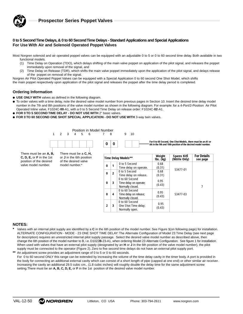
Prospector Series Poppet Valves
VAL-12-50 Littleton, CO USA Phone: 303-794-2611 www.norgren.com
0 to 5 Second Time Delays,& 0 to 60 Second Time Delays - Standard Applications and Special ApplicationsFor Use With Air and Solenoid Operated Poppet Valves
Most Norgren solenoid and air operated poppet valves can be equipped with an adjustable 0 to 5 or 0 to 60 second time delay. Both available in twofunctional models.(1) Time Delay on Operation (TDO), which delays shifting of the main valve poppet on application of the pilot signal, and releases the poppet
immediately upon removal of the signal, and(2) Time Delay on Release (TDR), which shifts the main valve poppet immediately upon the application of the pilot signal, and delays release
of the poppet on removal of the signal.Norgren Air Pilot Operated Poppet Valves can be equipped with a Special Application 0 to 60 second One Shot Model, which shiftsthe main poppet respectively upon application of the pilot signal and releases the poppet after the time delay period is completed.
Ordering Information● USE ONLY WITH valves as defined in the following diagram.● To order valves with a time delay, note the desired valve model number from previous pages in Section 10. Insert the desired time delay model
number in the 7th and 8th positions of the valve model number as shown in the following diagram. For example: for a 4-Port/2-Position Air PilotOperated Inline valve, F1024C-00-A1, with a 0 to 5 Second Time Delay on release order: F1024C-02-A1.
● FOR 0 TO 5 SECOND TIME DELAY - DO NOT USE WITH 2" basic valves.● FOR 0 TO 60 SECOND ONE SHOT SPECIAL APPLICATION - DO NOT USE WITH 3-way twin valves.
NOTES:* Valves with an internal pilot supply are identified by a C in the 6th position of the model number. See Figure 1(on following page) for installation.
ALTERNATE CONFIGURATION - MODE - 23 ONE SHOT TIME DELAY: The Alternate Configuration of Model 23 Time Delay (see next pagefor description) requires an unrestricted internal pilot supply passage. Select the desired valve model number as described above, thenchange the 6th position of the model number to B, i.e. D1022B-23-A1, when ordering Model 23 Alternate Configuration. See figure 1 for installation.When used with valves that have an external pilot supply (designated by an H or J in the 6th position of the valve model number), the pilotsupply must be connected to the operator (Figure 2). Zero to five second time delays do not have an external pilot supply port.
** An adjustment screw provides an adjustment range of 0 to 5 or 0 to 60 seconds.For 0 to 60 second ONLY this range can be extended by increasing the volume of the time delay cavity in the timer body. A port is provided inthe body for connecting an additional external cavity which can consist of a short length of pipe (capped at one end) or other similar air receiver.Increasing the cavity an additional 29.5 cubic cm., (1.8 cubic inches) will roughly double the delay time for the same adjustment screwsetting.There must be an A, B, C, D, E, or F in the 1st position of the desired valve model number.
There must be an A, B,C, D, E, or F in the 1stposition of the desiredvalve model number.
There must be a C, H,or J in the 6th positionof the desired valvemodel number.*
Position in Model Number1 2 3 4 5 6 7 8 9 10
0 0
Time Delay Models**Weight Spares Kit§ For Details
lbs. (kg) (Nitrile Only) see page
0 10 to 5 Second 0.68Time delay on operate. (0.31)
53477-010 2
0 to 5 Second 0.68Time delay on release. (0.31)0 to 60 Second
0.950 3 Time delay on operate;(0.43)Normally closed. 7
0 to 60 Second0.950 4 Time delay on release;
(0.43)53477-03
Normally closed.0 to 60 Second
0.952 3 One Shot Time delay;(0.43)Normally open.
For 0 to 60 Second, One Shot Models, there must be an A1 orAA in the 9th and 10th position of the desired model number.
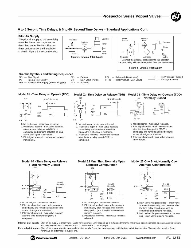
Prospector Series Poppet Valves
Littleton, CO USA Phone: 303-794-2611 www.norgren.com VAL-12-51
Pilot Air SupplyThe pilot air supply to the time delaymust be filtered and regulated asdescribed under Medium. For besttimer performance, the installationshown in Figure 2 is recommended.
Connect the external pilot supply to the operator.The time delay will also be supplied from this connection.
Figure 2. External Pilot Supply
Figure 1. Internal Pilot Supply
Regulator5-Micron
Filter
Operator
Timer
MainValve
OtherSource
5-MicronFilter
Operator
Timer
MainValveRegulator Lubricator
0 to 5 Second Time Delays, & 0 to 60 Second Time Delays - Standard Applications Cont.
Graphic Symbols and Timing SequencesSIG — Pilot SignalIPS — Internal Pilot SupplyEPS — External Pilot Supply (Shown Plugged)
EXH — ExhaustMV — Main Valve (Piston)ACT — Actuated
REL — Released (Deactuated)IN PR — Inlet Pressure (Main Valve)
— Port/Passage Plugged— Passage Blocked
IPS MV
SIG
ON
OFF
ACT
RELMV
SIG
(0 to 5 Seconds)
TDR
1. No pilot signal - main valve released.2. Pilot signal applied - main valve actuates
after the time delay period (TDO) iscompleted and remains actuated so longas the pilot signal is sustained.
3. Pilot signal removed - main valve releasedimmediately.
1. No pilot signal - main valve released.2. Pilot signal applied - main valve actuates
immediately and remains actuated solong as the pilot signal is sustained.
3. Pilot signal removed - main valve releasesafter the time delay period (TDR) iscompleted.
Model 01 - Time Delay on Operate (TDO) Model 02 - Time Delay on Release (TDR)
1. No pilot signal - main valve released.2. Pilot signal applied - main valve actuates
after the time delay period (TDO) iscompleted and remains actuated so longas the pilot signal is sustained.
3. Pilot signal removed - main valve releasedimmediately.
Model 03 - Time Delay on Operate (TDO)Normally Closed
EXH
EPS
IPS MV
SIG
ONOFFACTREL
MV
SIG
(0 to 60 Seconds)
TDO
IPS MV
SIG
ON
ACT
RELMV
SIG
(0 to 5 Seconds)
TDO
1. No pilot signal - main valve released.2. Pilot signal applied - main valve actuates
immediately, then releases after the timedelay period (one shot) is completed andremains released.
3. Pilot signal removed - main valve remainsreleased.
EXH
MV
SIG
ONOFFACTREL MV
SIG
(0 to 60 Seconds)
ONESHOT
Model 23 One Shot, Normally OpenStandard Configuration
1. Main valve inlet pressurized - main valveactuates immediately, then releases afterthe time delay period (one shot) iscompleted and remains released.
2. Main valve inlet pressure reduced to zeropsig - main valve remains released.
Model 23 One Shot, Normally OpenAlternate Configuration
EXH
MV
SIG
ONOFFACTREL MV
SIG
(0 to 60 Seconds)
TDO
1. No pilot signal - main valve released.2. Pilot signal applied - main valve actuates
immediately and remains actuated so longas the pilot signal is sustained.
3. Pilot signal removed - main valve releasesafter the time delay period (TDR) iscompleted.
Model 04 - Time Delay on Release(TDR) Normally Closed
EXH
EPS
IPS MV
SIG
ONOFFACTREL MV
SIG
(0 to 60 Seconds)
TDR
Internal pilot supply Shut off air supply to main valve. Cycle valve operator until trapped air is exhausted from the main valve piston chamber, operator, and time delay.You may also install a 2-way vent valve on the external pilot supply port.
External pilot supply Shut off air supply to main valve and the pilot supply. Cycle the valve operator until the trapped air is exhausted.You may also install a 2-way vent valve on external pilot supply line.

Prospector Series Poppet ValvesAll Dimensions in Inches (mm)
VAL-12-52 Littleton, CO USA Phone: 303-794-2611 www.norgren.com
Smooth Start Valves Dimensions
Basic 1/2-Inch A00*5A, A00*5B, A00*5C & A00*5D.
1.50 (38.1)
* 2.06 (52.3)
3.00 (76.2)
1.56
(39.
5)3.
06 (
77.7
)
2.50
(63
.5)
3.74
(96
.0)
2.28
(57
.9)
2.13
(0.8
4)Adjustment Screw
2.28
(57.
9)
1.66
(42
.2)
7.1 (0.28)Dia. (2 pics)
2.13 (0.84)
1.00 (25.4)
1/4", 3/8", 1/2", 3/4"*1/4", 3/8", 1/2", 3/4"*
Basic 1-Inch A00*5E, A00*5F & A00*5G.
2.31(58.7)
4.62 (117.3)
3.31
(84
.1)
2.06
(52
.3)
4.10
(10
4.1)
1.13 (28.7)2.88 (73.2)
6.04
(15
3.4) 3.98
(10
1.1)
3.98
(10
1.1)
2.73
(69
.3)
2.38
(50
.5)
Adjustment Screw
10.4 (0.41)Dia. (2 pics)
*
3/4", 1", 1-1/4"* 3/4", 1", 1-1/4"*
* After final adjustment, drive pin in until flush to make adjustment tamper resistant.

Prospector Series Poppet ValvesAll Dimensions in Inches (mm)
Littleton, CO USA Phone: 303-794-2611 www.norgren.com VAL-12-53
Time Delay Valve Dimensions
2.13 (54)
2.84
(72
)
3.06 (78)
AdjustmentScrew
Exhaust 1/8"Do NotRestrict
0.69
(18)
0.69
(18)
1/4"
1/4"
AdjustmentScrew
3.06
(78
)
2.13
(54
)1.
03 (
26)
AdjustmentScrew
External Pilot Supply Port1/8"
3.06
(78
)
2.13
(54
)1.
53 (
39)
Exhaust Port1/8"
Do Not Restrict
External Cavity Port1/8"
Models 03, 04, 23
0 to 5 Second Time Delays 0 to 60 Second Time Delays
3-Port/2-Position Time Delays

VAL-12-54 Littleton, CO USA Phone: 303-794-2611 www.norgren.com
Inline Lockout Valves
● 3-way, manually operated, full flow lockout valvescan be locked in the closed position with a customersupplied padlock.
● In the closed position, these valves shut off the flowof air between the inlet and outlet ports and exhaustthe downstream air.
● Helps you comply to OSHA regulations, as they relateto OSHA regulation 29 CFR Part 1910, standard forlockout/tagout procedures.
For installation in 1/4" through 1-1/2" air lines.
Graphic Symbol
IN
OUT
EXHAUST
OptionsC0021A/D and C0023A/D Valves with fluorocarbon elastomers: Specify 1FA after
the desired valve model number.
C0022A/D and C0024A/D Valves with fluorocarbon elastomers: Specify 1EX afterthe desired valve model number.
C0021A/D Valves with tapped muffler base that accepts a muffler with 3/4" NPTmale threads: Specify 1M2 after the desired valve model number.Recommended muffler:MB006A.
C0022A/D Valves with tapped muffler base that accepts a muffler with 1" NPTmale threads: Specify 1M1 after the desired valve model number.Recommended muffler MB008A.
Note: Standard valves have a black handle. To order valves with a red handle,change the second position of the model number to an R (e.g., C0021A wouldchange to CR021A).
Order InformationPort Model Numbers Port Model Numbers Cv Factor
Basic Size Without With Basic Size Without With In-Out Out-ExhaustSize PTF Muffler Muffler Size ISO G Muffler Muffler Ports Ports1/2" 1/4" C0021A C0023A 1/2" G1/4 C0041A C0043A 4.2 6.0
3/8" C0021B C0023B G3/8 C0041B C0043B 6.6 6.61/2" C0021C C0023C G1/2 C0041C C0043C 9.3 7.93/4" C0021D C0023D G3/4 C0041D C0043D 12.6 8.6
1" 3/4" C0022A C0024A 1" G3/4 C0042A C0044A 10.6 8.01" C0022B C0024B G1 C0042B C0044B 16.2 9.2
1-1/4" C0022C C0024C G1-1/4 C0042C C0044C 25.3 8.91-1/2" C0022D C0024D – – – 22.4 10.0

Prospector Series Poppet ValvesAll Dimensions in Inches (mm)
Littleton, CO USA Phone: 303-794-2611 www.norgren.com VAL-12-55
Technical DataFluid: Compressed airMaximum Pressure: 300 psig (20.4 bar)Temperature Range: -20° to 175°F* (-29° to 79°C).*With a dew point of supply air less than air temperature below 35°F (2°C).Maximum Diameter of Lock Shackle: 5/16" (8mm)Materials of Construction
Valve Body: AliminumMuffler Base: ZincSpool, T-Handle, Muffler Shell: AluminumSpring Detent: Stainless SteelElastomers
Standard: Nitrile and PolyurethaneOptional: Fluorocarbon
Repair KitsC0021A/D and C0023A/D Valves:
Standard Elastomers: 53474-43Fluorocarbon Elastomers:
53474-44C0022A/D and C0024A/D Valves:
Standard Elastomers: 53475-34Fluorocarbon Elastomers: 53475-36
Replacement Mufflers* for C0021A/C0024D ValvesC0021A/D and C0023A/D Valves: ML004FC0022A/D and C0024A/D Valves: ML008F
*Contains all bolts and washers required to flange mount with the respective sized lockout valve.Lockout Hasp
Part Number: 54547-01The 1-1/2" diameter jaws can be used with all Norgren Inline, Olympian, andPoppet Lockout Valves except the T15. High-tensile steel affords extra protectionagainst unauthorized access. Red vinyl coated and plated to resist rust. Lockingholes accommodate padlocks up to 11/32" shackle diameter.
OPEN
CLOSE
A
D
F
E
C
B
OPEN
CLOSE
D
C
B
B C DWithout With Without With Without With
Valve Type A Muffler Muffler Muffler Muffler Muffler Muffler E FAll 1.87 9.33 11.78 2.90 5.35 6.97 7.97 4.00 2.00
1/2" basic (48) (237) (299) (74) (136) (177) (202) (102) (51)
All 2.26 12.07 15.72 4.13 7.78 8.65 10.46 5.00 2.501" basic (57) (307) (399) (105) (198) (220) (266) (127) (64)
Lockout Hasp54547-01

VAL-12-56 Littleton, CO USA Phone: 303-794-2611 www.norgren.com
Poppet Valves with IntegralLockout Slide
● 3-way, normally closed, solenoid operated,poppet valves are equipped with a manuallyoperated lockout slide that can be locked in theclosed position with a customer suppliedpadlock.
● In the closed position, the flow of air between theinlet and outlet ports is blocked and downstreamair is exhausted.
● The Inline Poppet Valves listed below havethreaded ports and install directly into the airline.
Technical DataFluid: Filtered & lubricated compressed air.
Main Valve Inlet Pressure: 30 to 150 psig (2.1 to 10.3 bar).
Temperature Range:-20° to 130°F* (-29° to 54°C).
*With a dew point of supply air less than air temperature below35°F (2°C).
Maximum Diameter of Lock Shackle: 5/16" (8mm)
Solenoid Operator SpecificationsStandard Voltage & Power Requirements:
120V/60Hz, 110V/50Hz; 7.5W
Optional Voltage & Power Requirements:12V/60Hz/50Hz; 7.5W24V/60Hz/50Hz; 7.5W48V/60Hz/50Hz; 7.5W240V/60Hz, 220V/50Hz; 7.5W12VDC; 7.5W24VDC; 6.0W
Duty: Continuous at 90 to 105% of rated voltage.
Coil Type: Class H. Molded with 3-pin plug-in connector.
Enclosure Classification: NEMA 4
Electrical Connectors on Receptacle:Industry Standard Form B with 11 mm spacing.
Connector Plug:Cable grip for cables 1/4" to 5/16" (6 to 8 mm) in diameter.
Override: Manual, nonlocking
Pilot Supply: Internal
Materials of ConstructionBody:
C0030A, C0030B, C0030C: Zinc All Others: Aluminum
Pistons, Poppets: Aluminum
Solenoid Operator:Body: ZincSolenoid: Copper, acetal, stainless steel
Elastomers: Nitrile.
Order InformationPort
Basic Size Model Exhaust PortSize PTF Number Cv Factor PTF1/2" 1/4" C0030A 2.4 1/2"
3/8" C0030B 3.2 1/2"1/2" C0030C 3.2 1/2"
1/2" 3/4" C0030D 6.1 3/4"1" 1" C0030E 13.2 1-1/4"
1-1/4" C0030F 16.6 1-1/4"2" 1-1/2" C0030G 44.8 1-1/2"
2" C0030H 49.5 2"

Prospector Series Poppet ValvesAll Dimensions in Inches (mm)
Littleton, CO USA Phone: 303-794-2611 www.norgren.com VAL-12-57
Poppet Valve Dimensions
Valve A (Rad) B C D E F G H J K L M N O P (Dia) R SC0030A/B/C/X 1.97 0.57 2.99 1.40 3.25 2.28 6.85 1.75 — — — — — — — — —
(50) (15) (76) (36) (83) (60) (174) (44) — — — — — — — — —C0030D 1.97 0.57 2.99 1.40 3.00 3.00 7.56 1.14 1.72 2.31 2.00 1.00 0.87 0.84 0.28 1.56 0.04
(50) (15) (76) (36) (76) (76) (192) (29) (44) (59) (51) (25) (22) (21) (7) (40) (1)C0030E/F 1.97 0.57 2.99 1.40 4.00 4.00 10.66 1.48 2.75 3.12 2.75 1.37 1.25 1.37 0.41 2.06 0.12
(50) (15) (76) (36) (102) (102) (271) (38) (70) (79) (70) (35) (32) (35) (10) (52) (3)C0030G/H 1.97 0.57 2.99 1.40 6.31 5.03 13.84 5.04 — — — — — — — — —
(50) (15) (76) (36) (160) (128) (352) (128) — — — — — — — — —C0030Y 1.97 0.57 2.99 1.40 4.19 † 3.00 6.85 5.10 — — — — — — — — —
(50) (15) (76) (36) (106) (76) (174) (130) — — — — — — — — —
Optional Voltages12V/60Hz/50Hz.........................1W3*24V/60Hz/50Hz.........................1W4*48V/60Hz/50Hz.........................1W5*240V/60Hz, 220V/50Hz ............1W6*12VDC ......................................1W1*24VDC ......................................1W2*
Optional ConnectorsCable grip with Indicator Light
24VDC or AC..........................1V4*120VDC or AC .......................1VB*
1/2" NPT Conduit .......................1V3*5-Ft. Molded Cord ......................1V5*5-Ft. Molded Cord, Indicator Light,
Surge Protection,PolarityIndependent
24VAC or DC .....................1V7*48VAC or DC .....................1V8*
* Specify the desired valve model numberfrom the previous page plus the desiredvoltage and/or connector option number.
Repair Kits for Poppet ValvesC0030A...............................53474-40C0030B...............................53474-40C0030C ..............................53474-40C0030D ..............................53474-40C0030E...............................53474-42C0030F...............................53474-42C0030G ..............................53474-41C0030H ..............................53474-41C0030X...............................53474-40C0030Y...............................53474-40
Mufflers For C0030 Valves1/2" NPT Male Thread .........MB004A3/4" NPT Male Thread .........MB006A1" NPT Male Thread ............MB008A1-1/4" NPT Male Thread......MBP10A1-1/2" NPT Female Thread ..MA012A2" NPT Female Thread ........MA016A
B A
C
G
HD C A
B
F
E
HO
J
G
AD
M
L
E
R
K
F
NS
C
B
P
A
E
G
H
DC
F
B
† 4.19 (106) for valves with 1/4", 3/8" and 1/2"ports; 5.67 (144) for valves with 3/4" ports.

Prospector Series Poppet Valves
VAL-12-58 Littleton, CO USA Phone: 303-794-2611 www.norgren.com
Flow (Cv) Factors. Flow ratings determined in accordance with ANSI (NFPA) T3.21.3,Pneumatic fluid power - Flow test procedure and reporting method - for fixed orifice components.
Basic PortValve Type Size Size Average Cv Factor
2-Port/2-Position Normally Closed Models Normally Open ModelsA to B Ports A to B Ports
1/2" 1/4" 2.1 2.33/8" 3.4 3.81/2" 5.3 5.43/4 6.5 6.3
1" 3/4" 10.7 12.01" 13.5 15.4
1-1/4" 16.3 17.9
2" 1-1/2" 34.0 —2" 39.6 —
3-Port/2-Position Normally Closed Models Normally Open ModelsIn to Out Ports Out to Exh Ports In to Out Ports Out to Exh Ports
Basic 1/4" 1/4" 1.5 1.8 1.5 1.83/8" 1.7 1.8 1.7 1.8
Basic 1/2" 1/4" 2.7 3.9 2.0 3.63/8" 3.6 4.9 3.1 4.61/2" 4.6 5.8 4.1 5.53/4" 5.4 6.2 4.9 5.8
Basic 1" 3/4" 11.2 13.3 10.6 12.81" 13.2 14.6 11.7 13.8
1-1/4" 16.6 18.4 12.0 15.5
3-Port/2-Position Multi-Directional A to C Ports A to B Ports C to A Ports B to A Ports1/2" 1/4" 2.5 2.0 2.3 2.1
3/8" 4.0 2.7 3.7 2.91/2" 5.7 3.4 4.7 4.03/4" 6.1 4.0 5.2 4.4
1" 3/4" 14.8 10.3 13.4 11.11" 17.7 13.2 14.0 14.1
1-1/4" 18.3 14.0 14.6 16.5
2" 1-1/2" 44.8 33.1 41.2 35.62" 49.5 40.0 46.1 42.8
4-Way 3-Way Twin, Normally Closed4-Port/2-Position (Inline Valves) In to Cyl 2 Cyl 1 to Exh In to Cyl 1 Cyl 2 to Exh
In to Cyls 1 & 2 Cyls 1 & 2 to Exh1/4" 1/4" 1.2 1.6 1.2 1.6
3/8" 1.4 1.6 1.4 1.6
1/2" 3/8" 3.0 4.5 3.1 4.31/2" 4.0 5.4 4.1 5.13/4" 4.8 5.8 5.0 5.4
1" 3/4" 10.3 13.1 11.0 12.51" 11.3 14.3 12.9 13.4
1-1/4" 11.6 14.5 14.3 13.7
All Subbase Valves In to Cyl 1 Port In to Cyl 2 Port Cyl 1 to Exh Port Cyl 2 to Exh Port1/2" 1/4" 1.8 2.0 3.4 3.2
3/8" 2.7 3.0 3.7 3.71/2" 3.2 3.6 4.7 4.73/4" 3.5 3.9 4.7 4.7
1" 3/4" 10.0 9.0 12.0 10.51" 11.9 10.3 12.7 11.1
1-1/4" 13.0 11.1 13.0 11.3
Type PortsDistributor A to C &
A to BSelector C to A &
B to AN.C. A to C &
B to AN.O. C to A &
A to B

Prospector Series Poppet Valves
Littleton, CO USA Phone: 303-794-2611 www.norgren.com VAL-12-59
Repair Kits and Factory Installed Fluorocarbon Elastomers• When requesting repair kits or information for your valve, give both main valve and operator model numbers exactly as found on their respective
nameplates.• Repair Kits - Repair kits contain all elastomers necessary to service one valve body, operator, or time delay. Order the appropriate valve body,
operator, and time delay repair kit as required to service your valve.• Valve Bodies and Operators with Factory Installed Fluorocarbon Elastomers - Valve bodies and some operators are available with fluorocarbon
elastomers for use when contaminants in the air system are incompatible with the standard nitrile elastomers. To order valves with fluorocarbonelastomers, specify the desired valve model number (from the preceding pages plus the Order With numbers given below. Be sure to specify theOrder With number for the valve body and the Order With number for the operator. Fluorocarbon elastomers are not available on Time Delays, on theA6 Air Operator, or on the standard C Series Solenoid Operators.
Order WithRepair Kit Factory Installed
Fluoro- FluorocarbonType Internal Variation Nitrile carbon ElastomerA101 B, C, E, F, H, J, K 53474-03 53474-14 53474-21 1EEA102 B, C, E, F, H, J, K 53475-01 53475-07 53475-13 1F2A103 B, C, H, J 53822-01 53909-01 53909-03 1F8B101 B, C, E, F, H, J, K 53474-03 53474-14 53474-21 1EEB102 B, C, E, F, H, J, K 53475-01 53475-07 53475-13 1F2C101 B, C, E, F, H, J, K 53474-03 53474-08 53474-15 1E8C102 B, C, E, F, H, J, K 53474-03 53474-08 53474-15 1E8C103 B, C, E, F, H, J, K 53475-01 53475-07 53475-13 1F2C104 B, C, H, J 53822-01 53909-02 53909-04 1F9C105 B, C, E, F, H, J, K 53474-03 53474-08 53474-15 1E8C106 B, C, E, F, H, J, K 53474-03 53474-08 53474-15 1E8C108 B, C, H, J 53822-01 53909-02 53909-04 1F9D101 B, E, F, H, K 53473-05 53473-06 53473-11D102 B, C, E, F, H, J, K 53474-03 53474-09 53474-16 1E9D103 B, C, E, F, H, J, K 53475-01 53475-08 53475-14 1F2D104 B, C, E, F, H, J, K 53475-01 53475-08 53475-14D107 B, C, F, H, J 53474-03 53474-24 53474-23D108 B, C, F, H, J 53475-01 53475-22 53475-21E101 B, F, H 53473-05 53473-07 53473-12E102 B, C, F, H, J 53474-03 53474-10 53474-17 1EAE103 B, C, F, H, J 53475-01 53475-09 53475-15E104 B, C, F, H, J 53475-01 53475-09 53475-15F101 B, C, E, H, K 53473-05 53473-08 53473-13 1E5F101 F 53473-16 53473-08* 53473-13F102 B, C, E, H, J, K 53474-06 53474-11 53474-18 1EBF102 F 53474-25 53474-11* 53474-18F103 B, C, E, H, J, K 53475-06 53475-10 53475-16F103 F 53475-25 53475-10* 53475-16F221 B, C, E, H, J, K 53474-06 53474-11 53474-18F221 F 53474-25 53474-11* 53474-18F222 B, C, E, H, J, K 53475-06 53475-10 53475-16F222 F 53475-25 53475-10* 53475-16F223 B, C, E, H, J, K 53474-06 53474-11 53474-18F223 F 53474-25 53474-11* 53474-18F224 B, C, E, H, J, K 53475-06 53475-10 53475-16F224 F 53475-25 53475-10* 53475-16F323 B, C, E, H, J, K 53474-06 53474-11 53474-18F323 F 53474-25 53474-11* 53474-18F324 B, C, E, H, J, K 53475-06 53475-10* 53475-16F324 F 53475-25 53475-10* 53475-16G102 B, C, E, H, J, K 53474-06 53474-12 53474-19 1ECG102 F 53474-25 53474-12* 53474-19 1ECG103 B, C, E, H, J, K 53475-06 53475-11 53475-17G103 F 53475-25 53475-11* 53475-17
Position in Model Number
VALVE BODY TIME DELAY OPERATOR
10 21A43 5
C621
1A109
0087
Order WithRepair Kit** Factory Installed
Fluoro- FluorocarbonType Nitrile carbon ElastomerA1 None Used None Used None UsedA4 None Used None Used None UsedA6 53476-01 — —CC — — —CE — — —CF — — Standard ††CN — — —CP — — —CR — — —CS — — —CT — 53478-13 Standard ††CU — — —CV — — —CW — — —CY — — —CZ — — Standard ††C0 53478-01 53478-13 53478-20C1 53478-01 53478-13 53478-20C2 53478-04 53478-13 53478-25C3 53478-04 53478-13 53478-25C4 53478-01 53478-13 53478-20C8 53478-01 53478-13 53478-20DA — — Standard ††D0 † 53478-02 53478-14 53478-24D1 † 53478-02 53478-14 53478-24D2 † 53478-05 53478-16 53478-26D3 † 53478-05 53478-16 53478-26D4 † 53478-01 53478-13 53478-20D5 † 53478-01 53478-13 53478-20D6 † 53478-04 53478-15 53478-25D7 † 53478-04 53478-15 53478-25D8 † 53478-04 53478-15 53478-25E1 53478-01 53478-13 53478-20E3 53478-04 53478-15 53478-25E8 53478-01 53478-13 53478-20F4 † 53478-02 53478-14 53478-24F5 † 53478-05 53478-16 53478-26F6 † 53478-01 53478-13 53478-20F7 † 53478-04 53478-15 53478-25M Series
53769-01 53769-02 53769-03
X0 53478-07 53478-17 53478-19X1 53478-07 53478-17 53478-19X2 † 53478-08 53478-18 53478-28X3 † 53478-08 53478-18 53478-28X4 † 53478-07 53478-17 53478-19X5 † 53478-07 53478-17 53478-19
Repair Kit(Nitrile
Type Only)01 53477-0102 53477-0103 53477-0304 53477-0305 Top 53477-0105 Bottom 53477-0309 53477-0310 53477-0322 Top 53477-0322 Bottom 53477-0323 53477-0324 53477-03
* Order Gasket 53045-02 when ordering fluorocarbon repair kits for main valves with internal variation F.** Solenoid operator repair kits do not include coils.† Order two kits to service these operators.†† The CF, CT, CZ, and DA operators are equipped with fluorocarbon elastomers.

Prospector Series Poppet Valves
VAL-12-60 Littleton, CO USA Phone: 303-794-2611 www.norgren.com
Prospector Popped Valve Product Number System
The following chart is intended to be used only as a general guide to the model number system. It is not designed to"build" model numbers.
POSITION IN MODEL NUMBER
1 Valve TypeA = 2-Port/2-Position, Normally Closed.B = 2-Port/2-Position, Normally Open.C = 3-Port/2-Position, Multi-Directional.D = 3-Port/2-Position, Normally Closed.E = 3-Port/2-Position, Normally Open.F = 4-Port/2-Position (4-way).G = 4-Port/2-Position, (3-way twin, Normally Closed).
7 & 8 Time Delay00 = None01 = 0 to 5 seconds. TDO Normally closed.02 = 0 to 5 seconds. TDR Normally closed.03 = 0 to 60 seconds. TDO Normally closed.04 = 0 to 60 seconds. TDR Normally closed.05 = 0 to 60 seconds. TDOR Normally closed.09 = 0 to 60 seconds. TDO Normally open.10 = 0 to 60 seconds. TDR Normally open.22 = 0 to 60 seconds. Delayed One Shot.23 = 0 to 60 seconds. One Shot Normally closed.24 = 0 to 60 seconds. TDO Normally closed.
2 Mounting Style1 = Inline, PTF ThreadsA = Inline, BSPP Threads2 = Subbase valve with subbase, PTF Threads3 = Subbase valve without subbase, PTF Threads
5 Port Size PTF2 = 1/4" Ports3 = 3/8" Ports4 = 1/2" Ports5 = 3/4" Ports6 = 1" Ports7 = 1-1/4" Ports8 = 1-1/2" Ports9 = 2" Ports0 = Subbase valve without subbase.
6 Internal VariationB = Internal Pilot Supply with unrestricted passage.C = Internal Pilot Supply with check valve.E = Sustaining Bleed Operation. Use only with momentary
signal solenoid operator. Has an internal pilot supply.F = Bleed Operation. Has an internal pilot supply with flow
restrictor. Use only with A1 and A4 air operators.H = External Pilot Supply.J = Vacuum Service. Has an external pilot supply
with heavy spring.K = Sustaining Bleed Operation. Use only with momentary
signal air operator.
3 & 4 Basic Size01 = 1/4" Basic, (Valve Types D, E, F)
1/2" Basic, (Valve Types A, B, C)02 = 1/2" Basic, (Valve Types C, D, E, F, G)
1" Basic, (Valve Types A, B)03 = 1" Basic, (Valve Types C, D, E, F, G)
2" Basic, (Valve Type A)04 = 1" Basic, (Valve Types D, E)
2" Basic, (Valve Type C)05 = 1/2" Basic, (Valve Type C with 1/4", 3/8" & 1/2" ports)06 = 1/2" Basic, (Valve Type C with 3/4" port)07 = 1/2" Basic, (Valve Type D with indicator pin)08 = 1" Basic, (Valve Type D with indicator pin)
2" Basic, (Valve Type C)21 = 1/2" Basic, (Valve Type F, Valve with subbase)22 = 1" Basic, (Valve Type F, Valve with subbase)23 = 1/2" Basic, (Valve Type F, Valve without subbase)24 = 1" Basic, (Valve Type F, Valve without subbase)
Valve Body OperatorTimeDelay
21 3 7 8 9 106 -4 5 -

Prospector Series Poppet Valves
Littleton, CO USA Phone: 303-794-2611 www.norgren.com VAL-12-61
9 & 10 Solenoid OperatorsStandard Solenoid Operators with Cable Grip Connector
for use with Basic 1" & 2" Valves (Optional for use with Basic 1/4" & 1/2" Valves)
CC = Single solenoid, nonlocking override, 8 WAC & DC.CR = Twin solenoid, nonlocking override, 8 WAC & DC.CU = Momentary signal solenoid, nonlocking override, 8 WAC & DCCK = CCW/24VDC & surge protector cable grip connector.*
Standard Solenoid Operators with Cable Grip Connector for use with Basic 1/2" & 1/4" Valves
CY = Single solenoid, nonlocking override, 7WAC, 6WDCCE = Single solenoid, locking override, 7WAC, 6WDCCS = Single solenoid, no override, 7WAC, 6WDC
CZ = Single solenoid, nonlocking override, 3.5WAC, 2WDCCF = Single solenoid, locking override, 3.5WAC, 2WDCDA = Single solenoid, no override, 3.5WAC, 2WDC
CW= Twin solenoid, nonlocking override, 7WAC, 6WDCCN = Twin solenoid, locking override, 7WAC, 6WDCCP = Twin solenoid, no override, 7WAC, 6WDC
CV = Momentary signal solenoid, nonlocking override, 7WAC, 6WDC.
Optional Solenoid Operators
C0 = Single, no override, 1/2" conduit.C1 = Single, locking override, 1/2" conduit.C2 = Single, no override, junction box.C3 = Single, locking override, junction box.C4 = Single, no override, low pressure, 1/2" conduit.C8 = Single, locking override, high pressure, 1/2" conduit.CT = Single, no override, high temperature, 1/2" conduit.
D0 = Momentary Signal, no override, 1/2" conduit.D1 = Momentary Signal, locking override, 1/2" conduit.D2 = Momentary Signal, no override, junction box.D3 = Momentary Signal, locking override, junction box.D4 = Twin, no override, 1/2" conduit.D5 = Twin, locking override, 1/2" conduit.D6 = Twin, no override, junction box.D7 = Twin, locking override, junction box.D8 = Twin, locking override, high pressure, junction box.
E1 = Single, nonlocking override, 1/2" conduit.E3 = Single, nonlocking override, junction box.E8 = Single, nonlocking override, high pressure, 1/2" conduit.
F4 = Momentary Signal, nonlocking override, 1/2" conduit.F5 = Momentary Signal, nonlocking override, junction box.F6 = Twin, nonlocking override, 1/2" conduit.F7 = Twin, nonlocking override, junction box.
X0 = Single, no override, hazardous location.X1 = Single, locking override, hazardous location.X2 = Momentary Signal, no override, hazardous location.X3 = Momentary Signal, locking override, hazardous location.X4 = Twin, no override, hazardous location.X5 = Twin, locking override, hazardous location.
9 & 10 Air OperatorsA1 = Single, PTF Threads
AA = Single, BSPP Threads
A4 = Twin, PTF Threads
A6 = Momentary signal, PTF ThreadsAf = Momentary Signal, BSPP Threads
9 & 10 Manual & Mechanical OperatorsMA = Plunger, spring return.
MB = Palm button, spring return.
MC = Hand Lever, horizontal, spring return.MD = Hand Lever, horizontal, detented.ME = Hand Lever, vertical, spring return.MF = Hand Lever, vertical, detented
MG = Clevis Lever, horizontal, spring return.MH = Clevis Lever, vertical, spring return.
MJ = Roller Lever, horizontal, spring return. MK = Roller Lever, vertical, spring return.
ML = Foot Pedal, horizontal, spring return.MM= Foot Pedal, vertical, spring return.
Voltage & Connector Options for Standard Solenoid OperatorsSpecify the desired valve model number (from pages 8, 10, or 12)plus the desired option part number from the following tables. Whenordering options for the CN, CP, CR, CU, CV, and CW operators,specify (Qty 2) after the option part number.
OperatorCD, CE, CN, CP, DA, CC,
Optional Voltages CS, CV, CW, CY CF, CZ CR, CU
12V/60Hz/50Hz 54452-34 — —
24V/60Hz/50Hz 54452-35 54469-24 54458-63
48V/60Hz/50Hz 54452-36 — —
120V/60Hz, 110V/50Hz Standard 54469-23 Standard
240V/60Hz, 220V/50Hz 54452-37 — 54458-62
6VDC — 54469-25 —
12VDC 54452-32 54469-21 54458-64
24VDC 54452-33 Standard 54458-60
110VDC — 54469-26 —
DA, CE, CF,CN, CP, CS, CC,
Optional Connectors CV, CW, CY, CZ CR, CU
Cable Grip with Indicator Light12VDC or AC — 54257-5424VDC or AC 54934-09 54257-55120VDC or AC 54934-03 54257-56220VDC or AC — 54257-57
1/2" NPT Conduit 54934-04 54933-18
5-ft. Molded Cord 54934-06 54933-17
5-ft. Molded Cord, Indicator Light, Surge Protection, Polarity Independent
24VAC or DC 54934-11 54933-0848VAC or DC 54934-12 54933-10120VAC or DC 54934-14 54933-12240VAC or DC 54934-16 54933-14


Littleton, CO USA Phone: 303-794-2611 www.norgren.com VAL-13-1
Section 13
ContentsFittings and Accessories . . . . . . . . . . . . . . . . . . . . . . . . .VAL-13-2Helpful Engineering Information . . . . . . . . . . . . . . . . . . .VAL-13-6Conversion Tables . . . . . . . . . . . . . . . . . . . . . . . . . . . . . .VAL-13-8Warning/Warranty . . . . . . . . . . . . . . . . . . . . . . . . . . . . . . .VAL-13-9Part Number Index . . . . . . . . . . . . . . . . . . . . . . . . . . . . .VAL-13-10
Accessories, and Helpful Engineering Information

Fittings and Accessories
VAL-13-2 Littleton, CO USA Phone: 303-794-2611 www.norgren.com
Operation:Flow Controls are meter out type. Compressed air passes freelyinto the push-in fitting portion of the flow control, flowing past thecheck seal and entering the connected component. In reverse flowconditions, air passes back into the flow control and energizes thecheck seal. Air must now flow through the metered passagecontrolled by the tapered adjustment needle of the flow control, andfinally exits through the push-in fitting end.Specifications
Fluid: Compressed air.Working Pressure: 5 to 150 psig (.3 to 10 bar)Temperature Range: 0° to 175°F (-20° to 80°C)
Materials of Construction:Banjo bolt, body, collet: Nickel plated brassTapered adjusting needle: BrassO-rings and check-seal: Silicone free NitrileSealing washer: Thermoplastic (10-32 UNF)Tubing: Nylon 11 or 12, 95 durometer polyurethane.Thread Sealant: Applied to the full circumference of tapered malethreads.
Free Flow In(Metered Flow Out)
Free Flow Out(Metered Flow In)
Tapered AdjustmentNeedle
Check Seal
Pneumatic Symbol
NPT Screw DriverTube or UNF SlotO.D. Thread Part Number Knob
10-32 UNF 12 VB0 0210 12 VA0 02105/32"
1/8 12 VB0 0218 12 VA0 0218
1/8 12 VB0 0418 12 VA0 04181/4"
1/4 12 VB0 0428 12 VA0 0428
1/4 12 VB0 0628 12 VA0 06283/8"
3/8 12 VB0 0638 12 VA0 0638
3/8 12 VB0 0738 –1/2"
1/2 12 VB0 0748 12 VA0 0748
VB0 Series
NPT NPT Screw Driver SlotFemale Male Part Number
1/8 1/8 12 VB0 18181/4 1/4 12 VB0 28283/8 3/8 12 VB0 38381/2 1/2 12 VB0 4848
Right Angle (Banjo) Flow Controls
For additional sizes, configurations, metric products, and technical specifications request catalog Fittings APC-101.
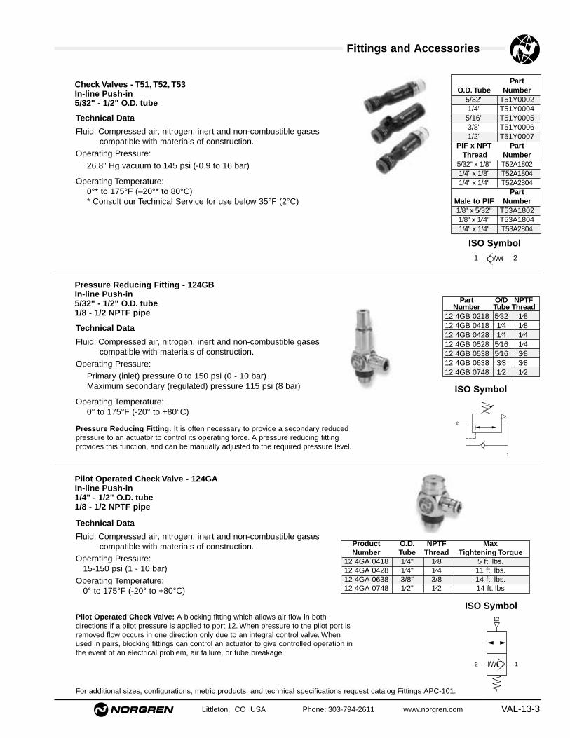
Fittings and Accessories
Littleton, CO USA Phone: 303-794-2611 www.norgren.com VAL-13-3
Technical Data
Fluid: Compressed air, nitrogen, inert and non-combustible gasescompatible with materials of construction.
Operating Pressure:26.8" Hg vacuum to 145 psi (-0.9 to 16 bar)
Operating Temperature:0°* to 175°F (–20°* to 80°C)* Consult our Technical Service for use below 35°F (2°C)
PartO.D. Tube Number
5/32" T51Y00021/4" T51Y00045/16" T51Y00053/8" T51Y00061/2" T51Y0007
PIF x NPT PartThread Number
5/32" x 1/8" T52A18021/4" x 1/8" T52A18041/4" x 1/4" T52A2804
PartMale to PIF Number1/8" x 5⁄32" T53A18021/8" x 1⁄4" T53A18041/4" x 1/4" T53A2804
1 2
Technical Data
Fluid: Compressed air, nitrogen, inert and non-combustible gasescompatible with materials of construction.
Operating Pressure:Primary (inlet) pressure 0 to 150 psi (0 - 10 bar)Maximum secondary (regulated) pressure 115 psi (8 bar)
Operating Temperature:0° to 175°F (-20° to +80°C)
Pressure Reducing Fitting - 124GBIn-line Push-in5/32" - 1/2" O.D. tube1/8 - 1/2 NPTF pipe
Check Valves - T51, T52, T53In-line Push-in5/32" - 1/2" O.D. tube
Part O/D NPTFNumber Tube Thread
12 4GB 0218 5⁄32 1⁄812 4GB 0418 1⁄4 1⁄812 4GB 0428 1⁄4 1⁄412 4GB 0528 5⁄16 1⁄412 4GB 0538 5⁄16 3⁄812 4GB 0638 3⁄8 3⁄812 4GB 0748 1⁄2 1⁄2
2
1
Technical Data
Fluid: Compressed air, nitrogen, inert and non-combustible gasescompatible with materials of construction.
Operating Pressure:15-150 psi (1 - 10 bar)
Operating Temperature:0° to 175°F (-20° to +80°C)
Pilot Operated Check Valve - 124GAIn-line Push-in1/4" - 1/2" O.D. tube1/8 - 1/2 NPTF pipe
Product O.D. NPTF MaxNumber Tube Thread Tightening Torque
12 4GA 0418 1⁄4" 1⁄8 5 ft. lbs.12 4GA 0428 1⁄4" 1⁄4 11 ft. lbs.12 4GA 0638 3/8" 3/8 14 ft. lbs.12 4GA 0748 1⁄2" 1⁄2 14 ft. lbs
12
12
For additional sizes, configurations, metric products, and technical specifications request catalog Fittings APC-101.
Pressure Reducing Fitting: It is often necessary to provide a secondary reducedpressure to an actuator to control its operating force. A pressure reducing fittingprovides this function, and can be manually adjusted to the required pressure level.
Pilot Operated Check Valve: A blocking fitting which allows air flow in bothdirections if a pilot pressure is applied to port 12. When pressure to the pilot port isremoved flow occurs in one direction only due to an integral control valve. Whenused in pairs, blocking fittings can control an actuator to give controlled operation inthe event of an electrical problem, air failure, or tube breakage.
ISO Symbol
ISO Symbol
ISO Symbol

Fittings and Accessories
VAL-13-4
Port ModelSize NPT
1⁄8 T55A18001⁄4 T55A28003⁄8 T55A38001⁄2 T55A48003⁄4 TC/5231 TC/524
Port Size NPT Model
1/8 T70A 1800
1/4 T70A 2800
3/8 T70A 3800
1/2 T70A 4800
Port Size NPT Model1/8 T1000A1800 1/4 T1000A2800 3/8 T1000A3800 1/2 T1000A4800
Port Size NPT Model1/8 T65A18001/4 T65A2800
Check Valves
In-line Flow ControlsQuick Exhaust Valves
Shuttle Valves
Littleton, CO USA Phone: 303-794-2611 www.norgren.com
Technical Data
Fluid: Compressed air, nitrogen, inert and non-combustible gasescompatible with materials of construction.
Operating Pressure:Cylinder pressure (Pc) 145 psi (10 bar) maxSensor supply pressure 43 to 145 psi (3 - 10 bar)Sensor switch pressure 14.5 psi (1.0 bar) typical
Operating Temperature:0° to 175°F (–20° to +80°C)
Product Tube NPTFNumber O/D Thread
12 4GD 0218 5/32" 1⁄8
12 4GD 0228 5/32" 1/8
Pressure Sensor Fitting -124GDIn-line Push-in5/32" O.D. tube1/8 - 1/4 NPTF pipe
ISO Symbol
Pneumatic Sensor Fittings: Provides an air signal when a cylinder has reached theend of travel. Sensor fittings operate by detecting the drop in exhaust pressure at theend of a stroke. They effectively offer an all-pneumatic option to the electrical reedswitch.
Port Size NPT Model1/8 T15Y0001 5/32 T15Y0002 1/4 T15Y0004 3/8 T15Y00061/2 T15Y0007
Push-In Flow Controls

Fittings and Accessories
Littleton, CO USA Phone: 303-794-2611 www.norgren.com VAL-13-5
Port Part PartSize Number NumberNPT (male) (female)1/8 MB001A MA001A1/4 MB002A MA002A3/8 MB003A MA003A1/2 MB004A MA004A3/4 MB006A MA006A1 MB008A MA008A
Port Size PartNPT Number
10-32 MS000A1/8 MS001A1/4 MS002A3/8 MS003A1/2 MS004A3/4 MS006A1 MS008A
Port PartSize NPT Number
10-32 UNF M/S01⁄8 C/S11⁄4 C/S23⁄8 C/S31⁄2 C/S43⁄4 C/S61 C/S8
Port Size PartNPT Number1/8 MV001A1/4 MV002A3/8 MV003A1/2 MV004A3/4 MV006A1 MV008A
Port Size PartNPT Number
10-32 UNF T20M05001/8 T20A18001/4 T20A28003/8 T20A38001/2 T20A4800
Port Size PartNPT Number1/8 MM001A1/4 MM002A3/8 MM003A1/2 MM004A
Quietaire™ Pneumatic Silencers
Standard-duty,sintered bronze
Standard-dutyporous plastic
Breather ventsintered bronze
Heavy duty speed controlsintered bronze
Standard-duty speed control porous plastic
Heavy-duty shell type
For additional sizes, configurations, metric products, and technical specifications request catalog Fittings APC-101.

Helpful Engineering Information
VAL-13-6 Littleton, CO USA Phone: 303-794-2611 www.norgren.com
Determining Proper Air Valve SizeMost manufacturers catalogs give flow rating Cv for the valve, which wasestablished using proposed National Fluid Power Association (NFPA)standard T3.21.3. The following tables and formulas will enable you toquickly size a valve properly. The traditional, often used, approach ofusing the valve size equivalent to the port in the cylinder can be verycostly. Cylinder speed, not port size, should be the determining factor.
The following Cv calculations are based upon simplified formulas whichyield results with acceptable accuracy under the following standardcondition:
Air at a temperature of 68°F (20°C)
Absolute downstream or secondary pressure must be 53% of absoluteinlet or primary pressure or greater. Below 53%, the air velocity maybecome sonic and the Cv formula does not apply. To calculate air flow toatmosphere, enter outlet pressure p2 as 53% of absolute p2. Pressuredrop ∆ P would be 47% of absolute inlet pressure. These valves havebeen calculated for a Cv = 1 in Table 3.
NomenclatureB Pressure drop factorC Compression factorCv Flow factorD Cylinder Diameter (IN)F Cylinder Area (SQ IN)L Cylinder Stroke (IN)p1 Inlet or Primary Pressure (PSIG)p2 Outlet or Secondary Pressure (PSIG)∆ P Pressure differential (p1 - p2) (PSID)q Air flow at actual condition (CFM)Q Air flow of free air (SCFM)t Time to complete one cylinder stroke (SEC)T Absolute temperature at operating pressure
Deg R = Deg F + 460 (R°)
Valve Sizing for Cylinder Actuation – (Method A)
Example:Cylinder size 4" Dia. x 10" stroke. Time to extend: 2 seconds. Inletpressure 90 psig. Allowable pressure drop 5 psid. Determine Cv.
Solution: Table 1 F = 12.57 sq inTable 2 C = 7.1
B = 21.6
Cv = 12.57 x 10 x 7.1 = .721.6 x 2 x 29
Select a valve that has a Cv factor of .7 or higher. In most cases a 1/4"valve would be sufficient.
It is considered good engineering practice to limitthe pressure drop ∆ P to approximately 10% ofprimary pressure p1. The smaller the allowablepressure drop, the larger the required valve willbecome.
After the minimum required Cv has been calculated,the proper size valve can be selected from thecatalog.
Table 1: Cylinder push bore area F for standard sizecylinders
Table 2: Compression Factor C and pressure dropFactor B.
cylinder area(Sq In) cylinder stroke Compression factor(see Table 1) F x (IN) L x (see Table 2) C
Cv =Pressure drop time to completefactor B x cylinder stroke t x 29(See Table 2) (SEC)
Bore Size Push Bore Bore Size Push BoreD (in) F (sq in) D (in) F (sq in)3/4" .44 4" 12.571" .79 4-1/2" 15.90
1-1/8" .99 5" 19.641-1/4" 1.23 6" 28.271-1/2" 1.77 7" 38.481-3/4" 2.41 8" 50.27
2" 3.14 10" 78.542-1/2" 4.91 12" 113.103-1/4" 8.30 14" 153.94
Inlet Compression Pressure Drop Factor BPressure Factor for various Pressure Drops ∆ P
(psig) C 2 psig 5 psid 10 psid 15 psid 20 psid10 1.7 6.520 2.4 7.8 11.830 3.0 8.9 13.6 18.040 3.7 9.9 15.3 20.5 23.650 4.4 10.8 16.7 22.6 26.4 29.060 5.1 11.7 18.1 24.6 29.0 32.070 5.8 12.5 19.3 26.5 31.3 34.880 6.4 13.2 20.5 28.2 33.5 37.490 7.1 13.9 21.6 29.8 35.5 39.9100 7.8 14.5 22.7 31.3 37.4 42.1110 8.5 15.2 23.7 32.8 39.3 44.3120 9.2 15.8 24.7 34.2 41.0 46.4130 9.8 16.4 25.6 35.5 42.7 48.4140 10.5 16.9 26.5 36.8 44.3 50.3150 11.2 17.5 27.4 38.1 45.9 52.1160 11.9 18.0 28.2 39.3 47.4 53.9170 12.6 18.5 29.0 40.5 48.9 55.6180 13.2 19.0 29.8 41.6 50.3 57.2190 13.9 19.5 30.6 42.7 51.7 58.9200 14.6 20.0 31.4 43.8 53.0 60.4210 15.3 20.4 32.1 44.9 54.3 62.0220 16.0 20.9 32.8 45.9 55.6 63.5230 16.7 21.3 33.5 46.9 56.8 64.9240 17.3 21.8 34.2 47.9 58.1 66.3250 18.0 22.2 34.9 48.9 59.3 67.7

Helpful Engineering Information
Littleton, CO USA Phone: 303-794-2611 www.norgren.com VAL-13-7
Inlet Air Flow Q (scfm) for various Air FlowPressure Pressure drops ∆ P at Cv = 1 Q (scfm) to
(psig) 2 psid 5 psid 10 psid 15 psid 20 psid atmosphere10 6.7 12.020 7.9 11.9 16.930 9.0 13.8 18.2 21.840 9.9 15.4 20.6 23.8 26.650 10.8 16.9 22.8 26.7 29.2 31.560 11.6 18.2 24.8 29.2 32.3 36.470 12.3 19.5 26.7 31.6 35.1 41.280 13.0 20.7 28.4 33.8 37.7 46.190 13.7 21.8 30.0 35.8 40.2 51.0100 14.4 22.9 31.6 37.8 42.5 55.9110 15.0 23.9 33.1 39.6 44.7 60.7120 15.6 24.9 34.5 41.4 46.8 65.6130 16.1 25.8 35.8 43.1 48.8 70.5140 16.7 26.7 37.1 44.7 50.7 75.3150 17.2 27.6 38.4 46.3 52.5 80.2160 17.7 28.4 39.6 47.8 54.3 85.1170 18.2 29.3 40.8 49.3 56.0 90.0180 18.7 30.1 42.0 50.7 52.7 94.8190 19.2 30.9 43.1 52.1 59.4 99.7200 19.6 31.6 44.2 53.4 60.9 104.6210 20.1 32.4 45.2 54.8 62.5 109.4220 20.5 33.1 46.3 56.1 64.0 114.3230 21.0 33.8 47.3 57.3 65.5 119.2240 21.4 34.5 48.3 58.6 66.9 124.0250 21.8 35.2 49.3 59.8 68.3 128.9
Valve Sizing with Cv = 1 Table (Method B)(For nomenclature see previous page)
This method can be used if the required air flow is known or hasbeen calculated with the formulas as shown below:
Example 1: Find air flow Q (scfm) if Cv is known.Cv (from valve catalog) = 1.8
Primary pressure p1 = 90 psigPressure drop across valve ∆ P = 5 psid
Flow through valve from Table 3 for Cv = 1:21.8scfm
Q = 1.8 x 21.8 = 39.2 scfm
Example 2: Find Cv if air flow Q (scfm) is given.Primary pressure p1 = 90 psigPressure drop ∆ P = 10 psidAir flow - Q = 60 scfm
Flow through valve from Table 3 for Cv = 1:30 scfm
A valve with a Cv of minimum 2 should be selected.
Example 3: Find Cv if air flow Q (scfm) toatmosphere is given (from catalog).
Primary pressure p1 = 90 psigAir flow to atmosphere Q = 100 scfm
Flow to atmosphere through valve from Table 3 forCv = 1:51 scfm
Flow given in catalog is equivalent to a valve withCv = 2. This conversion is often necessary to size avalve properly since some manufacturers do notshow the standard Cv to allow a comparison.
Example 4: Find Cv if cylinder size and stroke speedis known, using the formulas 1 and 3.
Primary pressure = 90 psigPressure drop across valve 5 psidCylinder size 4" dia. x 10" strokeTime to complete stroke 2 sec.
Q = .0273D2L
xp2 + 14.7
t 14.7
Q = qxp2 + 14.7
x528
14.7 T
1. (SCFM)
2. (SCFM)
Cv = 1.024 x Q
√∆ P x (p2 + 14.7)3. Proposed NFPA
Standard T3.21.3
����40
30
20
10
0
020 40 60 80 100 120 140
53% of inletpressure
120 psig inletpressure
Outlet or secondary valve pressure (psig)
Air Flow(SCFM)
Area where the Cv formulais valid and close approximation
Q = Cv of valve x air flow at Cv = 1 (scfm)
Cv = Air flow Q (scfm)Air flow at Cv = 1 (scfm)
Cv = Air flow to atmosphere Q (scfm)Air flow to atmosphere at Cv = 1 (scfm)
Cv = 60 scfm = 2.030
Cv = 100 = 2.051
Conversion of CFM to SCFM
Flow factor Cv (standard conditions)
Maximum pressure drop ∆ p across the valve should be lessthan 10% of inlet pressure p1.
Table 3: Air Flow Q (scfm) for Cv = 1
Flow Curves: How to read them
Q = .0273 42 x 10 x 85 + 14.7 = 14.81 scfm2 14.7
Cv = 1.024 x 14.81
= .7√5 x (85 + 14.7)

Conversion Tables
VAL-13-8 Littleton, CO USA Phone: 303-794-2611 www.norgren.com
°C = 5/9 (°F - 32)°F = 9/5 (°C + 32)°K = °C + 273.2°R = °F + 459.7
-100°C to +300°C°C °F °C °F-100 -148 29 84.2-90 -130 30 86.0-80 -112 31 87.8-70 -94 32 89.6-60 -76 33 91.4-50 -58 34 93.2-40 -40 35 95.0-35 -31 36 96.8-30 -22 37 98.6-25 -13 38 100.4-20 -4 39 102.2-15 5 40 104.0-10 14 45 113-5 23 50 1220 32 55 1311 33.8 60 1402 35.6 65 1493 37.4 70 1584 39.2 75 1675 41 80 1766 42.8 85 1857 44.6 90 1948 46.4 95 2039 48.2 100 21210 50 110 23011 51.8 120 24812 53.6 130 26613 55.4 140 28414 57.2 150 30215 59 160 32016 60.8 170 33817 62.6 180 35618 64.4 190 37419 66.2 200 39220 68 210 41021 69.8 220 42822 71.6 230 44623 73.4 240 46424 75.2 250 48225 77 260 50026 78.8 270 51827 80.6 280 53128 82.4 290 554
300 572
VOLUME
ENERGY
Length
AREA
WEIGHT
TEMPERATURE COMPARISON
TEMPERATURE CONVERSION
from/to cm3 liter in3 ft3 fl oz pt. qt. galcm3 1 .001 0.06102 3.53 x 10⁻⁵ .03381 .00211 0.106 2.64 x -10liter 1000 1 61.02 0.03532 33.81 2.113 10.057 .2642in3 16.39 0.01639 1 5379 x 10-4 .5541 .03463 0.01732 .00433ft3 2.83 x 10⁴ 28.32 1728 1 957.5 59.84 29.92 7.481fl oz 29.57 0.02957 1.805 0.00104 1 .06250 .03125 .00781pt 473.2 0.4732 28.88 0.01671 16 1 0.500 0.1250qt 946.4 0.9463 57.75 0.03342 32 2 1 0.2500gal (US) 3785 3.785 231 0.1337 128 8 4 1
bar 750.0 29.53 401.32 33.46 0.98592 14.504 1.01978
from/to mm Hg in Hg in H2O ft H2O atm lb/in2 kg/cm2
mm Hg 1 0.03937 0.5353 0.04460 .00132 0.01934 .00136
in Hg 25.40 1 13.60 1.133 .03342 0.4912 0.03453
in H2O 1.868 0.07355 1 0.08333 0.00246 0.03613 0.00254
ft H2O 22.42 0.8826 12 1 0.02950 0.4335 0.03048
atm 760 29392 406.8 33.9 1 14.70 1.033lb/in2 51.71 2.036 27.67 2.307 0.06805 1 0.07031kg/cm2 735.6 28.96 393.7 32.81 0.9678 14.22 1
PRESSURE
from/to cm m km in ft. milecm 1 0.01 1 x 10⁻⁵ 0.3937 0.03281 6.21 x 10⁻⁶m 100 1 0.001 39.37 3.281 6.21 x 10⁻⁴km 1 x 10⁵ 1000 1 3.94 x 10⁴ 3281 0.6214in 2.540 0.02540 2.54 x 10⁻⁵ 1 0.08333 1.58 x 10⁻⁵ft 30.48 0.3048 3.05 x 10⁻⁴ 12 1 1.89 x 10⁻⁴mile 1.61 x 10⁵ 1609 1.609 6.34 x 10⁴ 5280 1
from/to BTU Cal Joule Hp. hr. Kw hr.BTU 1 252.0 1055 3.93 x 10⁻⁴ 2.93 x 10⁻⁴Cal 0.397 1 4.186 1.56 x 10⁻⁵ 1.16 x 10⁻⁵joule 9.48 x 10⁻⁴ 0.2389 1 3.73 x 10⁻⁷ 2.78 x 10⁻⁷Hp hr 2545 6.41 x 10⁵ 2.68 x 10⁶ 1 0.7457Kw hr 3413 8.60 x 10⁵ 3.60 x 10⁶ 1.341 1
from/to cm4 m2 km2 in2 ft2
cm2 1 0.0001 1 x 10⁻¹⁰ 0.1550 0.00108m2 1 x 10⁴ 1 1 x 10⁻⁵ 1550 10.76km2 1 x 10¹⁰ 1x 10⁵ 1 1.55 x 10⁹ 1.08 x 10⁷in2 6.452 6.45 x 10⁻⁴ 6.45 x 10⁻¹⁰ 1 0.00694ft2 929.00 0.09290 9.29 x 10⁻⁸ 144 1
from/to gm kg oz lbgm 1 0.001 0.03527 0.00220kg 1000 1 35.27 2.205oz 28.35 0.02835 1 0.06250lb 453.6 0.4536 16 1
Warning and Warranty
Littleton, CO USA Phone: 303-794-2611 www.norgren.com VAL-13-9
WarningThese products are intended for use in industrial
compressed air systems only. Do not use these productswhere pressures and temperatures can exceed thoselisted under Specifications.
Before using these products with fluids other thanthose specified, for nonindustrial applications, life-support systems, or other applications not withinpublished specifications, consult Norgren.
Through misuse, age, or malfunction, componentsused in fluid power systems can fail in various modes.The system designer is warned to consider the failuremodes of all component parts used in fluid powersystems and to provide adequate safeguards to preventpersonal injury or damage to equipment in the event ofsuch failure modes. System designers must provide awarning to end users in the system instructionalmanual if protection against a failure mode cannotbe adequately provided.
System designers and end users are cautioned toreview specific warnings found in instruction sheetspacked and shipped with these products. Systemdesigners should also provide for all OSHA requirementsincluding Title 29 CFR 1910.147 Lockout/Tagout.
It should be recognized that warnings are valid for anyproduct, regardless of manufacturer, and are notrestricted to products manufactured by Norgren.Norgren's reputation for product quality and performanceis well established. We feel we have the additionalobligation to provide information or warnings tocustomers to assist them in applying our products in areasonable and safe manner.
WarrantyItems sold by Norgren are warranted to be free from
defects in materials and workmanship for a period of twoyears from the date of manufacture, provided said itemsare used according to Norgren's recommended usages.Norgren's liability is limited to the repair of, refund ofpurchase price paid for, or replacement in kind of, atNorgren's sole option, any items proved defective,provided the allegedly defective items are returned toNorgren prepaid. The warranties expressed above are inlieu of and exclusive of all other warranties.
There are no other warranties, expressed orimplied, except as stated herein. There are noimplied warranties of merchantability or fitness for aparticular purpose, which are specificallydisclaimed. Norgren's liability for breach of warrantyas herein stated is the exclusive remedy, and in noevent shall Norgren be liable or responsible forincidental or consequential damages, even if thepossibility of such incidental or consequentialdamages has been made known to Norgren.
Norgren reserves the right to discontinue manufactureof any product or change product materials, design, orspecifications.

Part Number Index
Littleton, CO USA Phone: 303-794-2611 www.norgren.comVAL-13-10
PART NUMBER SECTI0N0102144 VAL-3-30102144 VAL-3-70102144 VAL-3-903 VAL-7-303 0293 22 VAL-7-903 0294 22 VAL-7-1003 0296 22 VAL-7-1903 0335 22 VAL-7-1903 0366 22 VAL-7-1803 0367 22 VAL-7-1803 0368 22 VAL-7-1803 0400 22 VAL-703 0402 22 VAL-7-803 0403 22 VAL-7-1903 0404 22 VAL-7-1803 0408 22 VAL-7-1803 0409 22 VAL-7-803 0410 22 VAL-7-1003 0411 22 VAL-7-903 0414 22 VAL-7-1803 0417 22 VAL-7-803 0418 22 801 VAL-7-2103 0419 22 VAL-7-2003 0420 22 VAL-7-1803 0421 22 VAL-7-1803 0423 22 VAL-7-903 0424 22 VAL-7-2003 0425 22 VAL-7-2003 0427 22 VAL-7-903 0428 22 VAL-7-1903 0432 22 VAL-7-1003 0437 22 VAL-7-2003 0438 22 VAL-7-2003 0481 22 VAL-7-2103 0483 22 VAL-7-2103 0600 22 VAL-7-1403 0602 22 VAL-7-1403 0604 22 VAL-7-2603 0608 22 VAL-7-2603 0609 22 VAL-7-1403 0611 22 VAL-7-1503 0624 22 VAL-7-1503 0625 22 VAL-7-2603 0627 22 VAL-7-2703 0637 22 VAL-7-2603 0638 22 VAL-7-2603 0681 22 VAL-7-2703 0683 22 VAL-7-270588666 VAL-3-30588666 VAL-3-70588666 VAL-3-910319-K30 VAL-9-2310320-K01 VAL-9-1110320-K02 VAL-9-112221032 VAL-3-152221033 VAL-3-152221232 VAL-3-152221233 VAL-3-152362-07 VAL-10-1353473-05 VAL-12-1053473-05 VAL-12-1253473-05 VAL-12-2453473-05 VAL-12-2653473-05 VAL-12-3753473-05 VAL-12-3853473-05 VAL-12-4053473-05 VAL-12-9
53473-05 VAL-12-953474-02 VAL-12-2553474-03 VAL-12-1053474-03 VAL-12-1153474-03 VAL-12-2353474-03 VAL-12-2453474-03 VAL-12-2553474-03 VAL-12-3553474-03 VAL-12-3653474-03 VAL-12-3753474-03 VAL-12-3853474-03 VAL-12-3953474-03 VAL-12-753474-03 VAL-12-853474-03 VAL-12-953474-05 VAL-12-2453474-06 VAL-12-1253474-06 VAL-12-2653474-06 VAL-12-4053474-28 VAL-12-4953474-40 VAL-12-5753474-41 VAL-12-5753474-42 VAL-12-5753475-01 VAL-12-1053475-01 VAL-12-1153475-01 VAL-12-1253475-01 VAL-12-2353475-01 VAL-12-2453475-01 VAL-12-2553475-01 VAL-12-3553475-01 VAL-12-3653475-01 VAL-12-3753475-01 VAL-12-3853475-01 VAL-12-3953475-01 VAL-12-753475-01 VAL-12-853475-01 VAL-12-953475-03 VAL-12-2453475-06 VAL-12-1253475-06 VAL-12-2653475-06 VAL-12-4053475-26 VAL-12-4953477-06 VAL-12-1253478-07 VAL-10-1153761-26 VAL-12-1453761-27 VAL-12-1453761-28 VAL-12-1453761-29 VAL-12-1453761-30 VAL-12-1453761-31 VAL-12-1453761-32 VAL-12-1453761-33 VAL-12-1453822-01 VAL-12-1153822-01 VAL-12-2353822-01 VAL-12-2553822-01 VAL-12-3953822-01 VAL-12-753900-01 VAL-12-1453900-02 VAL-12-1453900-03 VAL-12-1453900-04 VAL-12-1453900-05 VAL-12-1453900-07 VAL-12-1453902-01 VAL-10-1353902-01 VAL-12-1453902-10 VAL-10-1353902-10 VAL-12-1453902-11 VAL-10-13
53902-11 VAL-12-1453902-12 VAL-10-1353902-12 VAL-12-1453902-13 VAL-12-1453902-14 VAL-10-1353902-14 VAL-12-1454237-56 VAL-10-2554237-56 VAL-10-2654237-56 VAL-10-2754237-56 VAL-10-2854237-56 VAL-10-2954237-57 VAL-10-2554237-57 VAL-10-2654237-57 VAL-10-2754237-57 VAL-10-2854237-58 VAL-10-2554237-58 VAL-10-2654237-58 VAL-10-2754237-58 VAL-10-2854237-59 VAL-10-2554237-59 VAL-10-2654237-59 VAL-10-2754237-59 VAL-10-2854237-59 VAL-10-2954344-16 VAL-10-2254344-17 VAL-10-1154452-01 VAL-10-1354452-01 VAL-11-2154452-01 VAL-12-1454452-02 VAL-10-1354452-02 VAL-11-2154452-02 VAL-12-1454452-03 VAL-10-1354452-03 VAL-11-2154452-03 VAL-12-1454452-04 VAL-10-1354452-04 VAL-12-1454452-05 VAL-11-2154452-05 VAL-12-1454452-06 VAL-10-1354452-06 VAL-12-1454452-07 VAL-10-1354452-07 VAL-11-2154452-07 VAL-12-1454453-01 VAL-11-2154458-50 VAL-12-1454458-51 VAL-12-1454458-52 VAL-12-1454458-53 VAL-12-1454458-54 VAL-12-1454462-01 VAL-11-2154462-02 VAL-10-1354462-02 VAL-11-2154462-03 VAL-11-2154462-04 VAL-10-1354462-04 VAL-11-2154462-09 VAL-10-1354462-09 VAL-11-2154462-10 VAL-10-1354462-10 VAL-11-2154463-01 VAL-11-2154463-50 VAL-11-2154463-51 VAL-11-2154469-01 VAL-10-1354469-01 VAL-11-2154469-01 VAL-12-1454469-01 VAL-3-354469-01 VAL-3-5
54469-01 VAL-3-754469-01 VAL-3-954469-02 VAL-10-1354469-02 VAL-11-2154469-02 VAL-12-1454469-02 VAL-3-354469-02 VAL-3-554469-02 VAL-3-754469-02 VAL-3-954469-03 VAL-10-1354469-03 VAL-11-2154469-03 VAL-12-1454469-03 VAL-3-354469-03 VAL-3-554469-03 VAL-3-754469-03 VAL-3-954469-04 VAL-10-1354469-04 VAL-11-2154469-04 VAL-12-1454469-04 VAL-3-354469-04 VAL-3-554469-04 VAL-3-754469-04 VAL-3-954469-05 VAL-10-1354469-05 VAL-11-2154469-05 VAL-12-1454469-06 VAL-10-1354469-06 VAL-11-2154469-06 VAL-12-1454469-07 VAL-3-354469-07 VAL-3-554469-07 VAL-3-754469-07 VAL-3-954469-08 VAL-3-354469-08 VAL-3-554469-08 VAL-3-754469-08 VAL-3-954574-50 VAL-11-2154580-61 VAL-11-2154644-52 VAL-8-2454644-52 VAL-9-2454672-89 VAL-11-2154673-89 VAL-11-2154674-89 VAL-11-2154677-50 VAL-11-1054677-50 VAL-11-1154677-50 VAL-11-1254677-50 VAL-11-1354677-50 VAL-11-2154677-50 VAL-11-854677-50 VAL-11-954677-51 VAL-11-1054677-51 VAL-11-1154677-51 VAL-11-1254677-51 VAL-11-1354677-51 VAL-11-2154677-51 VAL-11-854677-51 VAL-11-954677-52 VAL-11-1054677-52 VAL-11-1154677-52 VAL-11-1254677-52 VAL-11-1354677-52 VAL-11-2154677-52 VAL-11-954677-53 VAL-11-1054677-53 VAL-11-1154677-53 VAL-11-1254677-53 VAL-11-13
Part Page Part Page Part Page Part Page

Part Number Index
Littleton, CO USA Phone: 303-794-2611 www.norgren.com VAL-13-11
54677-53 VAL-11-2154677-53 VAL-11-854677-53 VAL-11-954677-54 VAL-11-1054677-54 VAL-11-1154677-54 VAL-11-1254677-54 VAL-11-1354677-54 VAL-11-2154677-54 VAL-11-854677-54 VAL-11-954677-55 VAL-11-1054677-55 VAL-11-1154677-55 VAL-11-1254677-55 VAL-11-1354677-55 VAL-11-2154677-55 VAL-11-854677-55 VAL-11-954692-50 VAL-11-2154692-51 VAL-11-2154693-50 VAL-11-1954693-51 VAL-11-1954932-01 VAL-10-1354932-02 VAL-10-1354932-03 VAL-10-1354932-04 VAL-10-1354932-05 VAL-10-1354932-06 VAL-10-1354932-07 VAL-10-1354932-08 VAL-10-1354932-09 VAL-10-1354932-10 VAL-10-1354932-21 VAL-10-1354932-22 VAL-10-1354932-24 VAL-10-1354932-25 VAL-10-1354932-26 VAL-10-1354932-27 VAL-10-1354932-28 VAL-10-1354932-29 VAL-10-1354932-30 VAL-10-1354934-01 VAL-11-2154934-01 VAL-3-354934-01 VAL-3-554934-01 VAL-3-754934-01 VAL-3-954934-02 VAL-11-2154934-02 VAL-3-354934-02 VAL-3-554934-02 VAL-3-754934-02 VAL-3-954934-05 VAL-11-2154934-05 VAL-3-354934-05 VAL-3-554934-05 VAL-3-754934-05 VAL-3-954934-08 VAL-11-2154934-08 VAL-3-354934-08 VAL-3-554934-08 VAL-3-754934-08 VAL-3-954934-21 VAL-11-2154934-21 VAL-3-354934-21 VAL-3-554934-21 VAL-3-754934-21 VAL-3-954934-30 VAL-11-2154934-30 VAL-3-554934-35 VAL-11-21
54934-35 VAL-3-554934-37 VAL-11-2154935-01 VAL-11-2154944-01 VAL-10-1354944-02 VAL-10-1354944-03 VAL-10-1354944-05 VAL-10-1354944-06 VAL-10-1354944-07 VAL-10-1354944-08 VAL-10-1354944-09 VAL-10-1354944-21 VAL-10-1354944-23 VAL-10-1354944-25 VAL-10-1354944-26 VAL-10-1354944-27 VAL-10-1354944-28 VAL-10-1354944-29 VAL-10-1354960-01 VAL-10-1354960-02 VAL-10-1354960-03 VAL-10-1354960-05 VAL-10-1354960-06 VAL-10-1354960-07 VAL-10-1354960-08 VAL-10-1354960-09 VAL-10-1354960-21 VAL-10-1354960-22 VAL-10-1354960-23 VAL-10-1354960-26 VAL-10-1354960-27 VAL-10-1354960-28 VAL-10-1354960-29 VAL-10-1355009-50 VAL-8-2465690-60 VAL-11-21A00*5 VAL-12-52A10 VAL-12B10 VAL-12C/943154/1 VAL-6-10C/P43149/* VAL-6-6C/P43154/* VAL-6-10C0021 VAL-12-54C0022 VAL-12-54C0023 VAL-12-54C0024 VAL-12-54C0030 VAL-12-57C0041 VAL-12-54C0042 VAL-12-54C0043 VAL-12-54C0044 VAL-12-54C10 VAL-12CQM/22152/3/23 VAL-5-8CQM/22253/3/23 VAL-5-8CQM/22354/3/23 VAL-5-8CQM/22354/3/26 VAL-5-8D10 VAL-12DRM1A-8-8B VAL-5-8DRM2A-8-8B VAL-5-8E10 VAL-12F10 VAL-12F22 VAL-12K VAL-10M/P43164 VAL-6-11M/P43165 VAL-6-11MA012A VAL-12-57MA016A VAL-12-57MB003A VAL-11-19MB004A VAL-11-19
MB004A VAL-12-57MB006A VAL-11-19MB006A VAL-12-57MB008A VAL-12-57MBP10A VAL-12-57MM004A VAL-11-19MM006A VAL-11-19MM113A VAL-11-19MN VAL-11MS003A VAL-11-19MS004A VAL-11-19MS006A VAL-11-19NUGGET 30 VAL-6-1RM1A-8B VAL-5-8RM2A-8B VAL-5-8RM3A-8B VAL-5-8SXE VAL-5SXP VAL-5V00021-C01 VAL-9-24V01 VAL-6-9V015416A-B26*1 VAL-6-10V015416A-B2621 VAL-6-9V015416A-B2631 VAL-6-9V02 VAL-6-4V025511A-B24*A VAL-6-4V025511A-B26*1 VAL-6-4V025516A-B24*A VAL-6-4V025516A-B26*1 VAL-6-4V025516A-Q11 VAL-6-7V025516A-Q12 VAL-6-7V025516A-Q13 VAL-6-7V025516A-Q14 VAL-6-7V025516A-Q1600 VAL-6-11V025516A-Q1700 VAL-6-12V025516A-Q19 VAL-6-8V025516A-Q20 VAL-6-12V025516A-Q2003 VAL-6-12V025516A-Q2103 VAL-6-12V025516A-Q2110 VAL-6-12V025516A-Q2230 VAL-6-11V025516A-Q2250 VAL-6-11V025516A-Q43 VAL-6-11V025526A-Q13 VAL-6-7V025722A-B26*1 VAL-6-5V03662A-Q21 VAL-6-12V055516A-Q21 VAL-6-12V08 VAL-8-5V085516A-Q01A8 VAL-8-20V085516A-Q02A2 VAL-8-20V085516A-Q02A8 VAL-8-20V085516A-Q03 VAL-8-20V085516A-Q03 VAL-8-21V085516A-Q0404 VAL-8-20V085516A-Q0406 VAL-8-20V085516A-Q0416 VAL-8-20V085516A-Q05AA VAL-8-20V085516A-Q0604 VAL-8-20V085516A-Q0608 VAL-8-20V085516A-Q0612 VAL-8-20V085516A-Q0616 VAL-8-20V085516A-Q0804 VAL-8-20V085516A-Q0808 VAL-8-20V085516A-Q0812 VAL-8-20V085516A-Q0816 VAL-8-20V085516A-Q0913 VAL-8-20V085516A-Q0918 VAL-8-20V085516A-Q0919 VAL-8-20V085516A-Q0953 VAL-8-20
V085516A-Q09B3 VAL-8-20V085516R-Q0913 VAL-8-21V085516R-Q0918 VAL-8-21V085516R-Q0919 VAL-8-21V085516R-Q0953 VAL-8-21V085516R-Q09B3 VAL-8-21V09 VAL-8-8V095516A-Q0604 VAL-8-22V095516A-Q0608 VAL-8-22V095516A-Q0612 VAL-8-22V095516A-Q0616 VAL-8-22V095516A-Q0620 VAL-8-22V095516A-Q0804 VAL-8-22V095516A-Q0812 VAL-8-22V095516A-Q0816 VAL-8-22V095516A-Q110 VAL-8-20V095516A-Q1100 VAL-8-21V095516A-Q1200 VAL-8-21V095516A-Q1601 VAL-2-14V095516A-Q160N VAL-8-21V095516R-Q1301 VAL-8-21V095516R-Q130G VAL-8-21V095516R-Q130N VAL-8-21V095516R-Q130R VAL-8-21V095516R-Q140G VAL-8-21V095516R-Q140N VAL-8-21V095516R-Q140R VAL-8-21V09556A-Q0808 VAL-8-22V10009-C00 VAL-1-8V10009-C00 VAL-2-17V10009-C00 VAL-2-22V10009-C00 VAL-4-11V10009-C00 VAL-4-21V10009-C00 VAL-4-25V10009-C00 VAL-4-7V10009-C00 VAL-8-21V10009-C00 VAL-9-23V10012-D13 VAL-8-24V10012-D13 VAL-9-24V10012-D18 VAL-8-24V10012-D18 VAL-9-24V10013-D03 VAL-8-24V10013-D03 VAL-9-24V10014-D03 VAL-8-24V10014-D03 VAL-9-24V10015-D03 VAL-8-24V10015-D03 VAL-9-24V10018-K00 VAL-8-21V10018-K00 VAL-8-24V10018-K00 VAL-9-24V10020-E01 VAL-2-13V10020-E01 VAL-2-17V10020-E01 VAL-2-21V10020-E01 VAL-9-23V10020-E03 VAL-2-13V10020-E03 VAL-2-17V10020-E03 VAL-2-21V10020-E03 VAL-9-23V10020-E05 VAL-2-13V10020-E05 VAL-2-17V10020-E05 VAL-2-21V10020-E05 VAL-9-23V10021-E01 VAL-8-23V10021-E01 VAL-9-23V10021-E03 VAL-8-23V10021-E03 VAL-9-23V10021-E05 VAL-8-23V10021-E05 VAL-9-23
Part Page Part Page Part Page Part Page

Part Number Index
Littleton, CO USA Phone: 303-794-2611 www.norgren.comVAL-13-12
V10021-E08 VAL-8-23V10021-E08 VAL-9-23V10021-E10 VAL-8-23V10021-E10 VAL-9-23V10024-K00 VAL-8-24V10024-K00 VAL-9-24V10025-A11 VAL-8-24V10025-A11 VAL-9-24V10025-A12 VAL-8-24V10025-A12 VAL-9-24V10025-A13 VAL-8-24V10025-A13 VAL-9-24V10025-A14 VAL-8-24V10025-A14 VAL-9-24V10025-A16 VAL-8-24V10025-A16 VAL-9-24V10025-A18 VAL-8-24V10025-A18 VAL-9-24V10025-A19 VAL-8-24V10025-A19 VAL-9-24V10026-N02 VAL-8-7V10026-N04 VAL-8-7V10026-N06 VAL-8-7V10026-N08 VAL-8-7V10026-N10 VAL-8-7V10026-N12 VAL-8-7V10027-D00 VAL-8-24V10027-D00 VAL-9-24V10028-G01 VAL-9-11V10028-G02 VAL-9-11V10028-G04 VAL-9-11V10028-G06 VAL-9-11V10028-G08 VAL-9-11V10028-G10 VAL-9-11V10028-G12 VAL-9-11V10028-N01 VAL-9-11V10028-N02 VAL-9-11V10028-N04 VAL-9-11V10028-N06 VAL-9-11V10028-N08 VAL-9-11V10028-N10 VAL-9-11V10028-N12 VAL-9-11V10038-G00 VAL-8-11V10038-N00 VAL-8-11V10040-C95 VAL-9-24V10040-C96 VAL-2-19V10040-C96 VAL-9-22V10040-C97 VAL-2-19V10040-C97 VAL-9-22V10040-C98 VAL-2-19V10040-C98 VAL-9-22V10041-C95 VAL-9-19V10041-C95 VAL-9-24V10041-C96 VAL-9-19V10041-C96 VAL-9-24V10075-K32 VAL-2-34V10089-C90 VAL-8-21V10089-C90 VAL-8-24V10089-C90 VAL-9-24V10121-G01 VAL-9-10V10121-N01 VAL-9-10V10122-G01 VAL-9-10V10122-N01 VAL-9-10V10176-K00 VAL-8-24V10230-R90 VAL-9-24V10238-C01 VAL-9-19V10238-C01 VAL-9-24V10239-C01 VAL-9-19
V10239-C01 VAL-9-24V10249-K00 VAL-9-24V10258-K00 VAL-8-24V10258-K00 VAL-9-24V10258-K01 VAL-8-24V10258-K02 VAL-8-21V10258-K02 VAL-8-24V10258-K03 VAL-8-24V10259-K00 VAL-8-24V10259-K00 VAL-9-24V10316-K30 VAL-9-24V10317-K30 VAL-9-24V10318-K30 VAL-9-24V10319-K30 VAL-2-17V10319-K30 VAL-2-22V1034-K00 VAL-8-24V10347-K30 VAL-9-24V10356-C01 VAL-9-19V10356-C01 VAL-9-24V10381-C01 VAL-9-19V10381-C01 VAL-9-24V10511-R01 VAL-8-7V10589-C95 VAL-8-24V10592-C01 VAL-4-11V10592-C01 VAL-4-21V10592-C01 VAL-4-25V10592-C01 VAL-4-7V10920-K01 VAL-8-21V109220-K01 VAL-8-21V11060-K01 VAL-2-22V11063-E01 VAL-2-13V11063-E01 VAL-2-21V11063-E03 VAL-2-13V11063-E03 VAL-2-17V11063-E03 VAL-2-21V11063-E05 VAL-2-13V11063-E05 VAL-2-17V11079-K01 VAL-2-14V11079-K01 VAL-2-22V111063-E01 VAL-2-17V112274-K01 VAL-2-17V11273-G01 VAL-9-21V11273-N01 VAL-9-21V11275-K01 VAL-2-17V11340-E03 VAL-1-17V11340-E03 VAL-1-19V11554-K30 VAL-1-8V11568-E01 VAL-1-8V11568-E03 VAL-1-8V11568-E05 VAL-1-8V11569-E01 VAL-1-18V11569-E01 VAL-1-8V11569-E03 VAL-1-18V11569-E03 VAL-1-18V11569-E05 VAL-1-18V11569-E05 VAL-1-18V11570-E01 VAL-1-17V11570-E01 VAL-1-18V11570-E01 VAL-1-18V11570-E01 VAL-1-19V11570-E03 VAL-1-17V11570-E03 VAL-1-18V11570-E03 VAL-1-19V11570-E03 VAL-1-8V11570-E05 VAL-1-17V11570-E05 VAL-1-18V11570-E05 VAL-1-19V11570-E05 VAL-1-8
V11574-D31 VAL-1-8V11574-K30 VAL-1-8V11588-E01 VAL-1-17V11588-E01 VAL-1-19V11589-E01 VAL-1-17V11589-E01 VAL-1-19V11590-E01 VAL-1-17V11590-E01 VAL-1-19V11591-E01 VAL-1-17V11591-E01 VAL-1-19V11592-E01 VAL-1-17V11592-E01 VAL-1-19V11598-E01 VAL-1-17V11598-E01 VAL-1-19V11599-E01 VAL-1-17V11599-E01 VAL-1-19V14 VAL-9V14517A-Q2119 VAL-9-20V14B517-Q2401 VAL-2-22V14B517A-Q03 VAL-9-21V14B517A-Q04 VAL-9-21V14B517A-Q2113 VAL-9-20V14B517A-Q2116 VAL-9-20V14B517A-Q2120 VAL-9-20V14B517A-Q2121 VAL-9-20V14B517A-Q2211 VAL-9-20V14B517A-Q240G VAL-9-22V14B517A-Q240N VAL-2-17V14B517A-Q240N VAL-9-22V14B517A-Q2700 VAL-2-21V14B517A-Q2700 VAL-9-22V14B517AQ2700 VAL-2-17V14B517AQ2800 VAL-9-22V14B517R-Q010G VAL-9-21V14B517R-Q010N VAL-9-21V14B517R-Q0604 VAL-9-21V14B517R-Q0608 VAL-9-21V14B517R-Q0612 VAL-9-21V14B517R-Q0616 VAL-9-21V14B517R-Q0620 VAL-9-21V14B517R-Q0704 VAL-9-22V14B517R-Q0712 VAL-9-22V14B517R-Q0716 VAL-9-22V14B517R-Q0804 VAL-9-21V14B517R-Q0808 VAL-9-21V14B517R-Q0812 VAL-9-21V14B517R-Q0816 VAL-9-21V14B517R-Q0913 VAL-9-21V14B517R-Q0918 VAL-9-21V14B517R-Q0953 VAL-9-21V14B517R-Q09B3 VAL-9-21V20 VAL-2V22 VAL-2-15V22B517AQ2700 VAL-2-17V25B628R-Q0708 VAL-9-22V40 VAL-4-4V40003-K30 VAL-9-24V405***D-C3 VAL-4-8V405*33A-X00*0 VAL-4-8V4055**D-C3 VAL-4-8V4055*3D-C3 VAL-4-8V4055*6D-C3 VAL-4-8V405537A-X0090 VAL-4-8V41 VAL-4-4V415***D-C3 VAL-4-8V415*33A-X00*0 VAL-4-8V4155**D-C3 VAL-4-8V4155*3D-C3 VAL-4-8
V4155*7D-C3 VAL-4-8V415537A-X0090 VAL-4-8V44 VAL-4-3V44A***D-C3 VAL-4-22V44A*33A-X00*0 VAL-4-22V44A5**D-C3 VAL-4-22V44A5*3D-C3 VAL-4-22V44A5*7D-C3 VAL-4-22V44A537A-X00*0 VAL-4-22V44A633A-X0020 VAL-4-21V44A733A-X0020 VAL-4-21V44A833A-X0020 VAL-4-21V45 VAL-4-3V45A***D-C3 VAL-4-22V45A*33A-X00*0 VAL-4-22V45A5**D-C3 VAL-4-22V45A5*7D-C3 VAL-4-22V45A537A-X00*0 VAL-4-22V45A633A-X0020 VAL-4-21V45A733A-X0020 VAL-4-21V45A833A-X0020 VAL-4-21V60 VAL-3-3V61 VAL-3V62 VAL-3V704**-P50 VAL-4-7V70400-K50 VAL-4-14V70400-K50 VAL-4-7V70401-A58 VAL-4-12V70401-A5B VAL-4-7V70401-P58 VAL-4-12V70401-P5B VAL-4-7V70402-P50 VAL-4-12V70404-P50 VAL-4-12V70406-P50 VAL-4-12V70408-P50 VAL-4-12V70410-P50 VAL-4-12V70412-P50 VAL-4-12V70421-K50 VAL-4-7V70422-K50 VAL-4-11V70422-K50 VAL-4-7V70423-K50 VAL-4-11V70423-K50 VAL-4-7V70424-B5C VAL-4-11V70424-B5C VAL-4-7V70424-R5C VAL-4-11V70424-R5C VAL-4-7V70425-15F VAL-4-7V70425-65F VAL-4-7V70425-85F VAL-4-7V70425-A5F VAL-4-7V70425-P5F VAL-4-7V70425-X5F VAL-4-11V70426-15F VAL-4-7V70426-65F VAL-4-7V70426-85F VAL-4-7V70426-A5F VAL-4-7V70426-P5F VAL-4-7V70426-X5F VAL-4-11V70427-K51 VAL-4-15V70427-K51 VAL-4-7V70427-K52 VAL-4-15V70427-K52 VAL-4-7V70427-K53 VAL-4-15V70427-K53 VAL-4-7V70427-K54 VAL-4-16V70427-K54 VAL-4-7V70428-K50 VAL-4-14V70428-K50 VAL-4-7
Part Page Part Page Part Page Part Page

Part Number Index
Littleton, CO USA Phone: 303-794-2611 www.norgren.com VAL-13-13
V70429-A50 VAL-4-13V70429-A50 VAL-4-7V70429-P50 VAL-4-13V70429-P50 VAL-4-7V70430-K50 VAL-4-13V70430-K50 VAL-4-7V70431-A5F VAL-4-11V70431-A5F VAL-4-7V70431-P5F VAL-4-7V70432-A5F VAL-4-7V70432-P5F VAL-4-7V70432-Y5F VAL-4-11V70435-P50 VAL-4-17V70435-P50 VAL-4-7V70436-B00 VAL-4-17V70436-B00 VAL-4-21V70436-B00 VAL-4-7V70436-K00 VAL-4-17V70436-K00 VAL-4-21V70436-K00 VAL-4-7V70436-R00 VAL-4-17V70436-R00 VAL-4-21V70436-R00 VAL-4-7V705**RA0 VAL-4-21V70500-KA0 VAL-4-21V70500-KA0 VAL-4-27V70501-BAB VAL-4-21V70501-BAB VAL-4-26V70501-RAB VAL-4-21V70501-RAB VAL-4-26V70502-RA0 VAL-4-26V70504-RA0 VAL-4-26V70506-RA0 VAL-4-26V70508-RA0 VAL-4-26V70510-RA0 VAL-4-26V70512-RA0 VAL-4-26V70522-K00 VAL-4-21V70522-K00 VAL-4-25V70523-K00 VAL-4-21V70523-K00 VAL-4-25V70524-CAC VAL-4-21V70524-CAC VAL-4-25V70524-SAC VAL-4-21V70524-SAC VAL-4-25V70525-2AF VAL-4-21V70525-8AF VAL-4-21V70525-BAE VAL-4-25V70525-BAF VAL-4-21V70525-PAF VAL-4-21V70525-RAF VAL-4-21V70525-XAF VAL-4-25V70525-YAF VAL-4-21V70526-2AF VAL-4-21V70526-8AF VAL-4-21V70526-BAE VAL-4-25V70526-BAF VAL-4-21V70526-PAF VAL-4-21V70526-RAF VAL-4-21V70526-XAF VAL-4-25V70526-YAF VAL-4-21V70527-KA1 VAL-4-21V70527-KA1 VAL-4-28V70527-KA2 VAL-4-21V70527-KA2 VAL-4-28V70527-KA3 VAL-4-21V70527-KA3 VAL-4-28V70527-KA4 VAL-4-21V70527-KA4 VAL-4-28
V70528-KA0 VAL-4-21V70528-KA0 VAL-4-27V70529-BA0 VAL-4-21V70529-BA0 VAL-4-27V70529-RA0 VAL-4-21V70529-RA0 VAL-4-27V70530-KA0 VAL-4-21V70530-KA0 VAL-4-27V70531-KA0 VAL-4-11V70531-KA0 VAL-4-21V70531-KA0 VAL-4-25V70531-KA0 VAL-4-7V70532-K00 VAL-4-21V70532-K00 VAL-4-7V70535-BA0 VAL-4-21V70535-RA0 VAL-4-21V70535-RA0 VAL-4-29V71020-KB1 VAL-5-8V71020-KC1 VAL-5-8V71022-KB2 VAL-5-8V71022-KB3 VAL-5-8V71022-KB4 VAL-5-8V71022-KC2 VAL-5-8V71022-KC3 VAL-5-8V71022-KC4 VAL-5-8V71022-KD2 VAL-5-8V71022-KD3 VAL-5-8V71022-KD4 VAL-5-8V82030-KD1 VAL-5-8VE1ASCN1-M1200 VAL-1-17VE1ASCN1-M1200 VAL-1-19VE1DNFNB-64640 VAL-2-27VE1DPCRS-CN12P VAL-2-38VE1FBC0S-M1210 VAL-2-26VE1FBC0S-M1210 VAL-2-39VE1FBC0S-M121D VAL-2-26VE1FBC0S-M121D VAL-2-39VE1FBC0S-M1230 VAL-2-26VE1FBC0S-M1230 VAL-2-39VE1FBC0S-M123D VAL-2-26VE1FBC0S-M123D VAL-2-39VE1FBC0S-M1250 VAL-2-26VE1FBC0S-M1250 VAL-2-39VE1FBC0S-M125D VAL-2-26VE1FBC0S-M125D VAL-2-39VE1FBC8E-M1210 VAL-2-26VE1FBC8E-M1210 VAL-2-39VE1FBC8E-M121D VAL-2-39VE1FBC8E-M1230 VAL-2-26VE1FBC8E-M1230 VAL-2-39VE1FBC8E-M123D VAL-2-26VE1FBC8E-M123D VAL-2-39VE1FBC8E-M1250 VAL-2-26VE1FBC8E-M1250 VAL-2-39VE1FBC8E-M125D VAL-2-26VE1FBC8E-M125D VAL-2-39VE1FBC8E-M232D VAL-2-26VE1FBC8S-M1210 VAL-2-26VE1FBC8S-M1210 VAL-2-39VE1FBC8S-M121D VAL-2-26VE1FBC8S-M121D VAL-2-39VE1FBC8S-M1230 VAL-2-26VE1FBC8S-M1230 VAL-2-39VE1FBC8S-M123D VAL-2-26VE1FBC8S-M123D VAL-2-39VE1FBC8S-M1250 VAL-2-26VE1FBC8S-M1250 VAL-2-39VE1FBC8S-M125D VAL-2-26
VE1FBC8S-M125D VAL-2-39VE1FBCPS-M1830 VAL-2-32VE1FBCSA-M1203 VAL-2-26VE1FBCSA-M1203 VAL-2-40VE1FBCSA-M1210 VAL-2-26VE1FBCSA-M1210 VAL-2-40VE1FBCSB-M1203 VAL-2-40VE1FBCSB-M1210 VAL-2-26VE1FBCSB-M1210 VAL-2-40VE1FBCSC-M1203 VAL-2-26VE1FBCSC-M1203 VAL-2-40VE1FBCSC-M1210 VAL-2-26VE1FBCSC-M1210 VAL-2-40VE1FBCTA-M1203 VAL-2-26VE1FBCTA-M1203 VAL-2-40VE1FBCTA-M1210 VAL-2-26VE1FBCTA-M1210 VAL-2-40VE1FBCTB-M1203 VAL-2-26VE1FBCTB-M1203 VAL-2-40VE1FBCTB-M1210 VAL-2-26VE1FBCTB-M1210 VAL-2-40VE1FBCTC-M1203 VAL-2-26VE1FBCTC-M1203 VAL-2-40VE1FBCTC-M1210 VAL-2-26VE1FBCTC-M1210 VAL-2-40VE1IBCRS-CN09S VAL-2-38VE1ICRS-CN09P VAL-2-38VE1MP098-00400 VAL-2-17VE1MP09B-00400 VAL-2-14VE1MP22B-00400 VAL-2-22VE2 VAL-2-23VE2CAFNB-64640 VAL-2-27VE2CAFNB-64640 VAL-2-31VE2DNFNB-64640 VAL-2-31VE2DPFNB-64640 VAL-2-27VE2DPFND-64640 VAL-2-27VE2DPFND-64640 VAL-2-29VE2EPFNB-64640 VAL-2-29VE2FB0MA-00040 VAL-2-33VE2FB0MA-00080 VAL-2-33VE2FBC9P VAL-2-38VE2FBC9P-00000 VAL-1-17VE2FBC9P-00000 VAL-1-19VE2FBC9P-9S010 VAL-1-17VE2FBC9P-9S010 VAL-1-19VE2FBC9P-9S010 VAL-2-38VE2FBC9P-9S030 VAL-1-17VE2FBC9P-9S030 VAL-1-19VE2FBC9P-9S030 VAL-2-38VE2FBC9P-9S050 VAL-1-17VE2FBC9P-9S050 VAL-1-19VE2FBC9P-9S050 VAL-2-38VE2FBC9S VAL-2-38VE2FBC9S-00000 VAL-1-17VE2FBCPL-00000 VAL-2-36VE2FBCPR-00000 VAL-2-36VE2FBCPS-M1800 VAL-2-38VE2FBCPS-M1810 VAL-2-32VE2FBCPS-M1810 VAL-2-38VE2FBCPS-M1830 VAL-2-38VE2FBCPS-M1850 VAL-2-32VE2FBCPS-M1850 VAL-2-38VE2FBECL-00000 VAL-2-35VE2FBECR-00000 VAL-2-35VE2FBIMF-04000 VAL-2-33VE2FBIMF-08000 VAL-2-33VE2FBIMG-04000 VAL-2-33VE2FBIMG-08000 VAL-2-33
VE2FBVPL-00000 VAL-2-34VE2FBVPR-00000 VAL-2-34VE2IBFNC-64640 VAL-2-27VE2IBFNC-64640 VAL-2-30VE2IBFNE-64640 VAL-2-27VE2IBFNE-64640 VAL-2-30VEAFBCSB-M1203 VAL-2-26VM10 VAL-1VM101511AB213B VAL-1-22VM101511AB313B VAL-1-22VM101517AB213B VAL-1-21VM101517AB313B VAL-1-21VM101522AB213B VAL-1-22VM101522AB313B VAL-1-22VM101527AB213B VAL-1-21VM101527AB313B VAL-1-21VM101611AB213B VAL-1-22VM101611AB313B VAL-1-22VM101622AB213B VAL-1-22VM101622AB313B VAL-1-22VM101A11AB213B VAL-1-20VM101A11AB313B VAL-1-20VM101A11AB313B VAL-1-20VM101A22AB213B VAL-1-20VM101A22AB313B VAL-1-20VM101B11AB213B VAL-1-20VM101B11AB313B VAL-1-20VM101B22AB213B VAL-1-20VM101B22AB313B VAL-1-20VM101BFNB-00 VAL-1-12VM101C11AB213B VAL-1-21VM101C11AB213B VAL-1-21VM101C11AB313B VAL-1-21VM101C22AB213B VAL-1-21VM101C22AB313B VAL-1-21VM103511AB213B VAL-1-22VM103511AB313B VAL-1-22VM103517AB213B VAL-1-21VM103517AB213B VAL-1-21VM103517AB313B VAL-1-21VM103517AB313B VAL-1-21VM103522AB213B VAL-1-22VM103522AB313B VAL-1-22VM103527AB213B VAL-1-21VM103527AB313B VAL-1-21VM103611AB213B VAL-1-22VM103611AB313B VAL-1-22VM103622AB213B VAL-1-22VM103622AB313B VAL-1-22VM103A11AB213B VAL-1-20VM103A11AB313B VAL-1-20VM103A22AB213B VAL-1-20VM103A22AB313B VAL-1-20VM103B11AB213B VAL-1-20VM103B11AB313B VAL-1-20VM103B22AB213B VAL-1-20VM103B22AB313B VAL-1-20VM103C11AB213B VAL-1-21VM103C11AB313B VAL-1-21VM103C22AB213B VAL-1-21VM103C22AB313B VAL-1-21VM104511AB213B VAL-1-22VM104511AB313B VAL-1-22VM104517AB213B VAL-1-21VM104517AB313B VAL-1-21VM104522AB213B VAL-1-22VM104527AB213B VAL-1-21VM104527AB313B VAL-1-21
Part Page Part Page Part Page Part Page

Part Number Index
Littleton, CO USA Phone: 303-794-2611 www.norgren.comVAL-13-14
VM104611AB213B VAL-1-22VM104611AB313B VAL-1-22VM104622AB213B VAL-1-22VM104622AB313B VAL-1-22VM104A11AB213B VAL-1-20VM104A11AB313B VAL-1-20VM104A22AB213B VAL-1-20VM104A22AB313B VAL-1-20VM104B11AB213B VAL-1-20VM104B11AB313B VAL-1-20VM104B22AB213B VAL-1-20VM104B22AB313B VAL-1-20VM104C11AB213B VAL-1-21VM104C11AB313B VAL-1-21VM104C22AB213B VAL-1-21VM104C22AB313B VAL-1-21VM106511AB213B VAL-1-22VM106511AB313B VAL-1-22VM106517AB213B VAL-1-21VM106517AB313B VAL-1-21VM106517AQ0108 VAL-1-10VM106517AQ010Y VAL-1-10VM106517AQ0118 VAL-1-10VM106517AQ011Y VAL-1-10VM106517AQ0128 VAL-1-10VM106517AQ012Y VAL-1-10VM106517AQ0131 VAL-1-10VM106517AQ0132 VAL-1-10VM106517AQ0133 VAL-1-10VM106517AQ0202 VAL-1-10VM106517AQ020X VAL-1-10VM106517AQ0212 VAL-1-10VM106517AQ021X VAL-1-10VM106517AQ022X VAL-1-10VM106517AQ0231 VAL-1-10VM106517AQ0232 VAL-1-10VM106517AQ0233 VAL-1-10VM106517AQ0300 VAL-1-8VM106517AQ0300 VAL-1-9VM106517AQ0301 VAL-1-8VM106517AQ0301 VAL-1-9VM106517AQ0302 VAL-1-8VM106517AQ0302 VAL-1-9VM106517AQ0303 VAL-1-8VM106517AQ0303 VAL-1-9VM106517AQ04 VAL-1-11VM106517AQ0404 VAL-1-11VM106517AQ0406 VAL-1-11VM106517AQ0408 VAL-1-11VM106517AQ0410 VAL-1-11VM106517AQ0412 VAL-1-11VM106517AQ05 VAL-1-11VM106517AQ0510 VAL-1-11VM106517AQ0512 VAL-1-11VM106517AQ0516 VAL-1-11VM106517AQ0804 VAL-1-18VM106517AQ0806 VAL-1-18VM106517AQ1604 VAL-1-15VM106517AQ1604 VAL-1-17VM106517AQ1606 VAL-1-15VM106517AQ1606 VAL-1-17VM106517AQ1608 VAL-1-15VM106517AQ1608 VAL-1-17VM106517AQ222 VAL-1-10VM106517AQ3604 VAL-1-17VM106517AQ3606 VAL-1-15VM106517AQ3606 VAL-1-17VM106517AQ3608 VAL-1-15
VM106517AQ3608 VAL-1-17VM106517AQ4604 VAL-1-15VM106517AQ4604 VAL-1-17VM106517AQ4606 VAL-1-17VM106517AQ4608 VAL-1-15VM106517AQ4608 VAL-1-17VM106517AQ6604 VAL-1-15VM106517AQ6604 VAL-1-17VM106517AQ6606 VAL-1-15VM106517AQ6606 VAL-1-17VM106517AQ6608 VAL-1-15VM106517AQ6608 VAL-1-17VM106517AQ9604 VAL-1-15VM106517AQ9604 VAL-1-17VM106517AQ9606 VAL-1-15VM106517AQ9606 VAL-1-17VM106517AQ9608 VAL-1-15VM106517AQ9608 VAL-1-17VM106517AQA604 VAL-1-15VM106517AQA604 VAL-1-17VM106517AQA606 VAL-1-15VM106517AQA606 VAL-1-17VM106517AQA608 VAL-1-15VM106517AQA608 VAL-1-17VM106517UQ1804 VAL-1-15VM106517UQ1804 VAL-1-17VM106517UQ1806 VAL-1-15VM106517UQ1806 VAL-1-17VM106517UQ1808 VAL-1-15VM106517UQ1808 VAL-1-17VM106517UQ3804 VAL-1-15VM106517UQ3804 VAL-1-17VM106517UQ3804 VAL-1-17VM106517UQ3806 VAL-1-15VM106517UQ3808 VAL-1-15VM106517UQ3808 VAL-1-17VM106517UQ4804 VAL-1-15VM106517UQ4804 VAL-1-17VM106517UQ4806 VAL-1-15VM106517UQ4806 VAL-1-17VM106517UQ4808 VAL-1-15VM106517UQ4808 VAL-1-17VM106517UQ6804 VAL-1-15VM106517UQ6804 VAL-1-17VM106517UQ6806 VAL-1-15VM106517UQ6806 VAL-1-17VM106517UQ6808 VAL-1-15VM106517UQ6808 VAL-1-17VM106517UQ9804 VAL-1-15VM106517UQ9804 VAL-1-17VM106517UQ9806 VAL-1-15VM106517UQ9806 VAL-1-17VM106517UQ9808 VAL-1-15VM106517UQ9808 VAL-1-17VM106517UQA804 VAL-1-15VM106517UQA804 VAL-1-17VM106517UQA806 VAL-1-15VM106517UQA806 VAL-1-17VM106517UQA808 VAL-1-15VM106517UQA808 VAL-1-17VM106522AB213B VAL-1-22VM106522AB313B VAL-1-22VM106527AB231B VAL-1-21VM106527AB313B VAL-1-21VM106611AB213B VAL-1-22VM106611AB313B VAL-1-22VM106622AB213B VAL-1-22VM106622AB313B VAL-1-22
VM106A11AB213B VAL-1-20VM106A11AB313B VAL-1-20VM106A22AB213B VAL-1-20VM106A22AB313B VAL-1-20VM106B11AB213B VAL-1-20VM106B11AB313B VAL-1-20VM106B22AB213B VAL-1-20VM106B22AB313B VAL-1-20VM106C11AB213B VAL-1-21VM106C11AB313B VAL-1-21VM106C22AB213B VAL-1-21VM106C22AB313B VAL-1-21VM107511AB213B VAL-1-22VM107511AB313B VAL-1-22VM107511UB213B VAL-1-23VM107511UB313B VAL-1-23VM107517AB213B VAL-1-21VM107517AB313B VAL-1-21VM107517UB213B VAL-1-23VM107517UB313B VAL-1-23VM107522AB213B VAL-1-22VM107522AB313B VAL-1-22VM107522UB213B VAL-1-23VM107522UB313B VAL-1-23VM107527AB213B VAL-1-21VM107527AB313B VAL-1-21VM107527UB213B VAL-1-23VM107527UB313B VAL-1-23VM107611AB213B VAL-1-22VM107611AB313B VAL-1-22VM107611UB213B VAL-1-23VM107611UB313B VAL-1-23VM107622AB213B VAL-1-22VM107622AB313B VAL-1-22VM107622UB213B VAL-1-23VM107622UB313B VAL-1-23VM107A11AB213B VAL-1-20VM107A11AB313B VAL-1-20VM107A11UB213B VAL-1-23VM107A11UB313B VAL-1-23VM107A22AB213B VAL-1-20VM107A22AB313B VAL-1-20VM107A22UB213B VAL-1-23VM107A22UB313B VAL-1-23VM107B117B213B VAL-1-23VM107B11AB213B VAL-1-20VM107B11AB313B VAL-1-20VM107B11UB313B VAL-1-23VM107B22AB213B VAL-1-20VM107B22AB313B VAL-1-20VM107B22UB213B VAL-1-23VM107B22UB313B VAL-1-23VM107C11AB213B VAL-1-21VM107C11AB313B VAL-1-21VM107C11UB213B VAL-1-23VM107C11UB313B VAL-1-23VM107C22AB213B VAL-1-21VM107C22AB313B VAL-1-21VM107C22UB213B VAL-1-23VM107C22UB313B VAL-1-23VM109511AB213B VAL-1-22VM109511AB313B VAL-1-22VM109517AB213B VAL-1-21VM109517AB313B VAL-1-21VM109522AB213B VAL-1-22VM109522AB313B VAL-1-22VM109527AB213B VAL-1-21VM109527AB313B VAL-1-21
VM109611AB213B VAL-1-22VM109611AB313B VAL-1-22VM109622AB213B VAL-1-22VM109622AB313B VAL-1-22VM109A11AB213B VAL-1-20VM109A11AB313B VAL-1-20VM109A22AB213B VAL-1-20VM109A22AB313B VAL-1-20VM109B11AB213B VAL-1-20VM109B11AB313B VAL-1-20VM109B22AB213B VAL-1-20VM109B22AB313B VAL-1-20VM109C11AB213B VAL-1-21VM109C11AB313B VAL-1-21VM109C22AB213B VAL-1-21VM109C22AB313B VAL-1-21VM10A511AB213B VAL-1-22VM10A511AB313B VAL-1-22VM10A517AB213B VAL-1-21VM10A517AB313B VAL-1-21VM10A522AB213B VAL-1-22VM10A522AB313B VAL-1-22VM10A527AB213B VAL-1-21VM10A527AB313B VAL-1-21VM10A611AB213B VAL-1-22VM10A611AB313B VAL-1-22VM10A622AB213B VAL-1-22VM10AA11AB213B VAL-1-20VM10AA11AB313B VAL-1-20VM10AA22AB213B VAL-1-20VM10AA22AB213B VAL-1-20VM10AA22AB313B VAL-1-20VM10AB11AB213B VAL-1-20VM10AB11AB313B VAL-1-20VM10AB22AB213B VAL-1-20VM10AB22AB313B VAL-1-20VM10AC11AB213B VAL-1-21VM10AC11AB313B VAL-1-21VM10AC22AB213B VAL-1-21VM10AC22AB313B VAL-1-21VM10AS10A-00 VAL-1-12VM10CAFNB-00 VAL-1-12VM10CAFNB-00 VAL-1-13VM10DNFNB-00 VAL-1-12VM10DNFNB-00080 VAL-1-12VM10DNFNB-00080 VAL-1-12VM10DNFNB-00080 VAL-1-12VM10DNFNB-00081 VAL-1-14VM10DNFNB-00100 VAL-1-12VM10DNFNB-00100 VAL-1-12VM10DNFNB-00100 VAL-1-12VM10DNFNB-00101 VAL-1-14VM10DNFNB-00120 VAL-1-12VM10DNFNB-00120 VAL-1-12VM10DNFNB-00120 VAL-1-12VM10DNFNB-00121 VAL-1-14VM10DNFNB-00160 VAL-1-12VM10DNFNB-00160 VAL-1-12VM10DNFNB-00160 VAL-1-12VM10DNFNB-00161 VAL-1-14VM10DNFNB-00410 VAL-1-12VM10DNFNB-00810 VAL-1-12VM10DNFNB-00820 VAL-1-12VM10DNFNB-00830 VAL-1-12VM10DPFB-00080 VAL-1-13VM10DPFNB-00 VAL-1-12VM10DPFNB-00100 VAL-1-13VM10DPFNB-00120 VAL-1-13
Part Page Part Page Part Page Part Page

Part Number Index
Littleton, CO USA Phone: 303-794-2611 www.norgren.com VAL-13-15
VM10DPFNB-00160 VAL-1-13VM10LBFNB-00041 VAL-1-15VM10LBFNB-00061 VAL-1-15VM10LBFNB-00081 VAL-1-15VM10LBFNB-00101 VAL-1-15VM10LBFNB-00121 VAL-1-15VM10LBNB-00 VAL-1-13VM10R1FNB-00 VAL-1-12VM10R1FNB-00 VAL-1-13VN104522AB313B VAL-1-22X3 VAL-7X3 0296 22 VAL-7-23X3 0375 22 VAL-7-23X3 0386 22 VAL-7-22X3 0387 22 VAL-7-22X3 0388 22 VAL-7-22X3 0393 22 VAL-7-12X3 0394 22 VAL-7-13X3 0440 22 VAL-7-11X3 0442 22 VAL-7-11X3 0443 22 VAL-7-23X3 0444 22 VAL-7-22X3 0448 22 VAL-7-22X3 0449 22 VAL-7-11X3 0450 22 VAL-7-13X3 0451 22 VAL-7-12X3 0454 22 VAL-7-22X3 0455 22 VAL-7-22X3 0456 22 VAL-7-22X3 0457 22 VAL-7-11X3 0458 22 801 VAL-7-25X3 0459 22 VAL-7-25X3 0460 22 VAL-7-22X3 0461 22 VAL-7-22X3 0463 22 VAL-7-12X3 0464 22 VAL-7-24X3 0465 22 VAL-7-24X3 0467 22 VAL-7-12X3 0468 22 VAL-7-23X3 0472 22 VAL-7-13X3 0477 22 VAL-7-24X3 0478 22 VAL-7-24X3 0482 22 VAL-7-25X3 0484 22 VAL-7-25X3 0640 22 VAL-7-16X3 0642 22 VAL-7-16X3 0644 22 VAL-7-28X3 0648 22 VAL-7-28X3 0649 22 VAL-7-16X3 0651 22 VAL-7-17X3 0664 22 VAL-7-17X3 0665 22 VAL-7-29X3 0677 22 VAL-7-28X3 0678 22 VAL-7-28X3 0682 22 VAL-7-29X3 0684 22 VAL-7-29X3 3437 22 VAL-7-24X3 3438 22 VAL-7-24X3 3477 22 VAL-7-24X3 3478 22 VAL-7-24X3 3637 22 VAL-7-28X3 3638 22 VAL-7-28X3 3677 22 VAL-7-28X3 3678 22 VAL-7-28Z000 VAL-12-49
Part Page Part Page Part Page Part Page

www.norgren.com
Littleton, CO USA Phone: 303-794-2611 www.norgren.comVAL-13-16
www.usa.norgren.com is your complete source forthe latest Norgren product information, technicaltips, and other valuable pneumatic information.
Norgren USA’s website provides thelatest pneumatic’s informationavailable from Norgren USA. It isthe source for additional pneumaticproduct catalogs, CAD files, circuitdesign software, distributorlocations, customer service andapplication engineering contacts.
To access our website, set yourweb browser to:www.usa.norgren.com
5400 South Delaware StreetLittleton, Colorado 80120-1663Phone: 303-794-2611 Fax: 303-795-9487www.usa.norgren.come-mail: [email protected]

APC-104 Air Preparation Products
Littleton, CO USA Phone: 303-794-2611 www.norgren.com VAL-13-17
APC-104 showcases Norgren’s extensive line ofair preparation products for the pneumaticsindustry. You can contact your distributor andorder APC-104.

APC-101 Fittings
Littleton, CO USA Phone: 303-794-2611 www.norgren.comVAL-13-18
Norgren offers one of the most comprehensivepneumatic fittings lines in the industry. Contactyour distributor to order All Product CatalogAPC-101 to get all the information.

APC-103 Actuators
Littleton, CO USA Phone: 303-794-2611 www.norgren.com VAL-13-19
Norgren offers one of the most comprehensivepneumatic actuator lines in the industry.Contact your distributor to order All ProductCatalog APC-103 to get all the information.

Norgren CD Catalog (NCDC)
Littleton, CO USA Phone: 303-794-2611 www.norgren.comVAL-13-20
Norgren’s CD Catalog is a Complete Source for NorgrenPneumatic Products, Solutions, Pricing, CAD, and a host ofadditional information.
NorgrenCD Catalog
NCDC
Norgren’s CD Catalog (NCDC) is the latest inproduct information and specifications. ThisCD contains complete product information,pricing, CAD files, pneumatic solutions, thelatest applications news, and a customer survey.Contact your local distributor and order partnumber NCDC.

Notes
Littleton, CO USA Phone: 303-794-2611 www.norgren.com VAL-13-21

Notes
Littleton, CO USA Phone: 303-794-2611 www.norgren.comVAL-13-22