normal and unusual transient events in irac images
TRANSCRIPT

Normal and Unusual Transient Events in IRAC Images
Brian M. Patten*a, Joseph L. Horaa, Giovanni G. Fazioa, Pauline Barmbya, Zhong Wanga,David Makovozb
aHarvard-Smithsonian Center for Astrophysics, 60 Garden St., Cambridge, MA USA 02138;bSpitzer Science Center, MS 220-6, Caltech, Pasadena, CA, USA 91125
ABSTRACT
The Spitzer Space Telescope Infrared Array Camera (IRAC) is a four-channel camera which uses two pairs of 256 x 256pixel InSb and Si:As IBC detectors to provide simultaneous images at 3.6, 4.5, 5.8, and 8 µm. IRAC experiences a fluxof cosmic rays that produce transient events in images from each of the arrays, with 2-4 pixels per second being affectedin an IRAC integration. The vast majority of these transient events can be adequately characterized so they can beeffectively detected and flagged by a pipeline software module. However, because of the nature of the arrays and theirarrangement in the camera structure, a small fraction of the cosmic ray hits on the IRAC produce transients withunusual morphologies that cannot be characterized in a general way. We present nominal cosmic ray rates observed forIRAC on-orbit and rates observed during a period of elevated solar proton flux following a series of X-class solar flaresin late 2003. We also present a guide for observers to help identify unusual transient events in their data. We commenton the physical nature of the production of many of these unusual transients and how this mechanism differs from theproduction of “normal” transient events.
Keywords: infrared detectors, cosmic rays, image processing and artifacts
1. INTRODUCTION
The Infrared Array Camera (IRAC) is one of three focal plane instruments in the Spitzer Space Telescope [1,2,3].IRAC is a four-channel camera that obtains simultaneous images at 3.6, 4.5, 5.8, and 8 µm. Two adjacent 5.2 x 5.2arcminute fields of view in the Spitzer focal plane are viewed by the four channels in pairs (3.6 and 5.8 µm; 4.5 and 8µm). All four detector arrays in the camera are 256 x 256 pixels in size, with the 3.6 and 4.5 µm channels using InSbarrays and the 4.5 and 8 µm channels using Si:As IBC arrays. Both detector types present pixels 30 µm x 30 µm to theincoming light, but the Si:As detectors are quite thick (30 µm) compared to the InSb detectors (7 µm). Figure 1 showsthe basic layout of the camera and the relative placement of the four focal plane assemblies (FPAs).
Launched on August 25, 2003, Spitzer was placed into an Earth-trailing solar orbit, which places the spacecraft welloutside any shielding effects of the Earth’s magnetosphere or enhancements in charged particle flux due to the Earth’sradiation belts [4]. Following launch, Spitzer underwent a 3-month evaluation during the In-Orbit Checkout (IOC) andScience Verification (SV) periods, during which the telescope was focused and a functional checkout of the instrumentsand observational templates was performed. During this time, IRAC was powered on for more than 900 hours,collecting in excess of 150,000 frames of calibration and science data. The camera is now being used regularly tocollect science data as a part of the nominal operations phase of the mission.
On orbit, the arrays experience a flux of high energy particles (“cosmic rays”). These cosmic rays consist primarily ofsolar protons and galactic cosmic rays – mostly protons, but also alpha particles and other heavier nuclei. These cosmicrays produce transient events in IRAC images. Transients are events where an apparent signal is produced in one ormore pixels over a time much shorter than the total exposure time for the image. These apparent signals are randomboth spatially and temporally. While the vast majority of these events can be adequately characterized so they can bedetected and flagged by the IRAC pipeline software, a small fraction of these events produce transients with unusualmorphologies that cannot be characterized in a general way. * [email protected]; phone 1 617 496-7770; fax 1 617 495-7490; cfa-www.harvard.edu
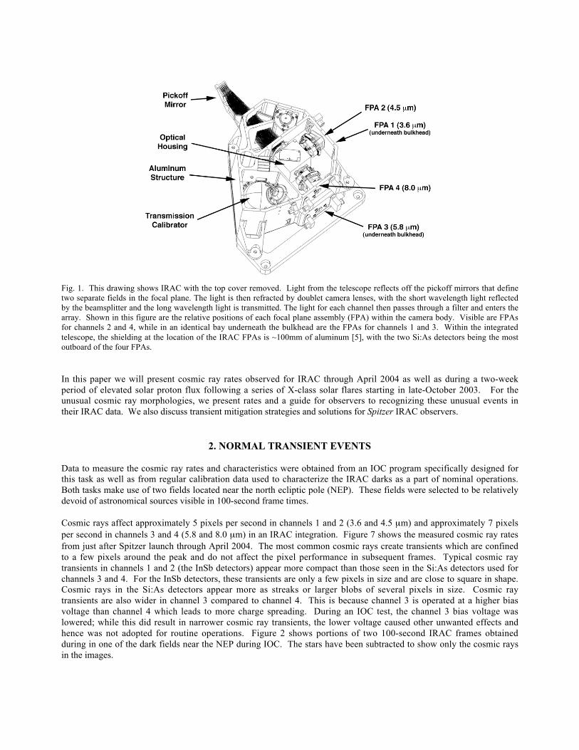
Fig. 1. This drawing shows IRAC with the top cover removed. Light from the telescope reflects off the pickoff mirrors that definetwo separate fields in the focal plane. The light is then refracted by doublet camera lenses, with the short wavelength light reflectedby the beamsplitter and the long wavelength light is transmitted. The light for each channel then passes through a filter and enters thearray. Shown in this figure are the relative positions of each focal plane assembly (FPA) within the camera body. Visible are FPAsfor channels 2 and 4, while in an identical bay underneath the bulkhead are the FPAs for channels 1 and 3. Within the integratedtelescope, the shielding at the location of the IRAC FPAs is ~100mm of aluminum [5], with the two Si:As detectors being the mostoutboard of the four FPAs.
In this paper we will present cosmic ray rates observed for IRAC through April 2004 as well as during a two-weekperiod of elevated solar proton flux following a series of X-class solar flares starting in late-October 2003. For theunusual cosmic ray morphologies, we present rates and a guide for observers to recognizing these unusual events intheir IRAC data. We also discuss transient mitigation strategies and solutions for Spitzer IRAC observers.
2. NORMAL TRANSIENT EVENTS
Data to measure the cosmic ray rates and characteristics were obtained from an IOC program specifically designed forthis task as well as from regular calibration data used to characterize the IRAC darks as a part of nominal operations.Both tasks make use of two fields located near the north ecliptic pole (NEP). These fields were selected to be relativelydevoid of astronomical sources visible in 100-second frame times.
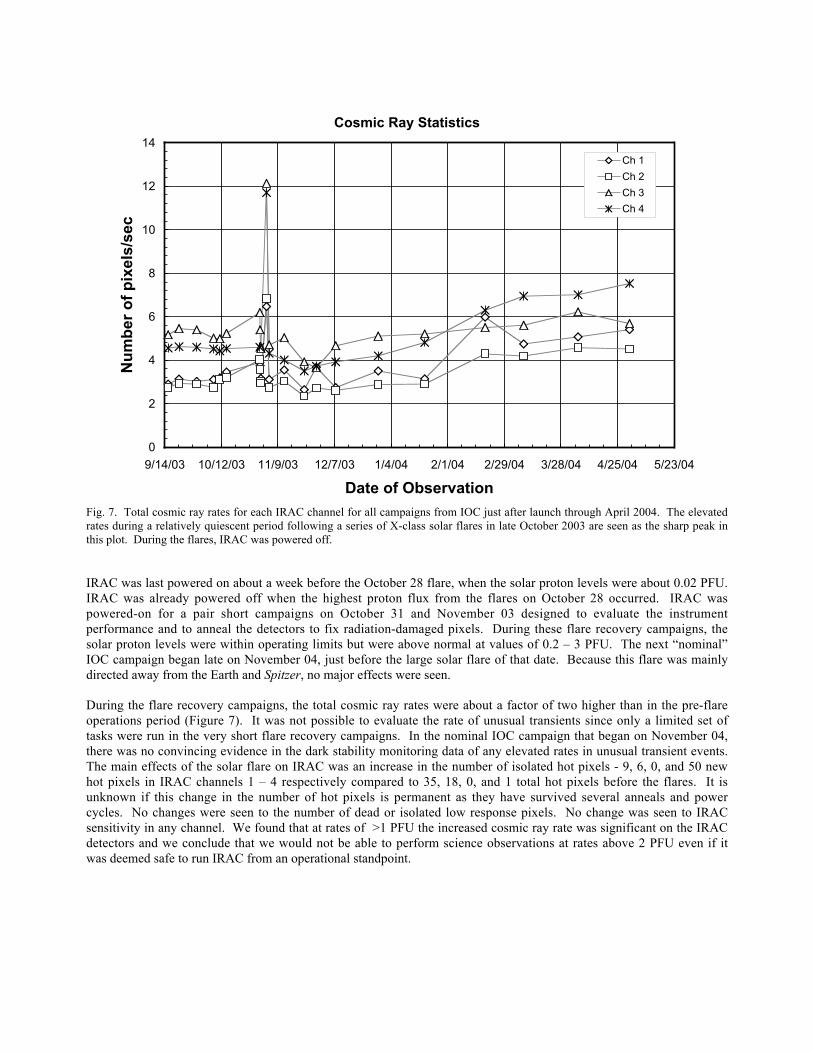
Cosmic rays affect approximately 5 pixels per second in channels 1 and 2 (3.6 and 4.5 µm) and approximately 7 pixelsper second in channels 3 and 4 (5.8 and 8.0 µm) in an IRAC integration. Figure 7 shows the measured cosmic ray ratesfrom just after Spitzer launch through April 2004. The most common cosmic rays create transients which are confinedto a few pixels around the peak and do not affect the pixel performance in subsequent frames. Typical cosmic raytransients in channels 1 and 2 (the InSb detectors) appear more compact than those seen in the Si:As detectors used forchannels 3 and 4. For the InSb detectors, these transients are only a few pixels in size and are close to square in shape.Cosmic rays in the Si:As detectors appear more as streaks or larger blobs of several pixels in size. Cosmic raytransients are also wider in channel 3 compared to channel 4. This is because channel 3 is operated at a higher biasvoltage than channel 4 which leads to more charge spreading. During an IOC test, the channel 3 bias voltage waslowered; while this did result in narrower cosmic ray transients, the lower voltage caused other unwanted effects andhence was not adopted for routine operations. Figure 2 shows portions of two 100-second IRAC frames obtainedduring in one of the dark fields near the NEP during IOC. The stars have been subtracted to show only the cosmic raysin the images.
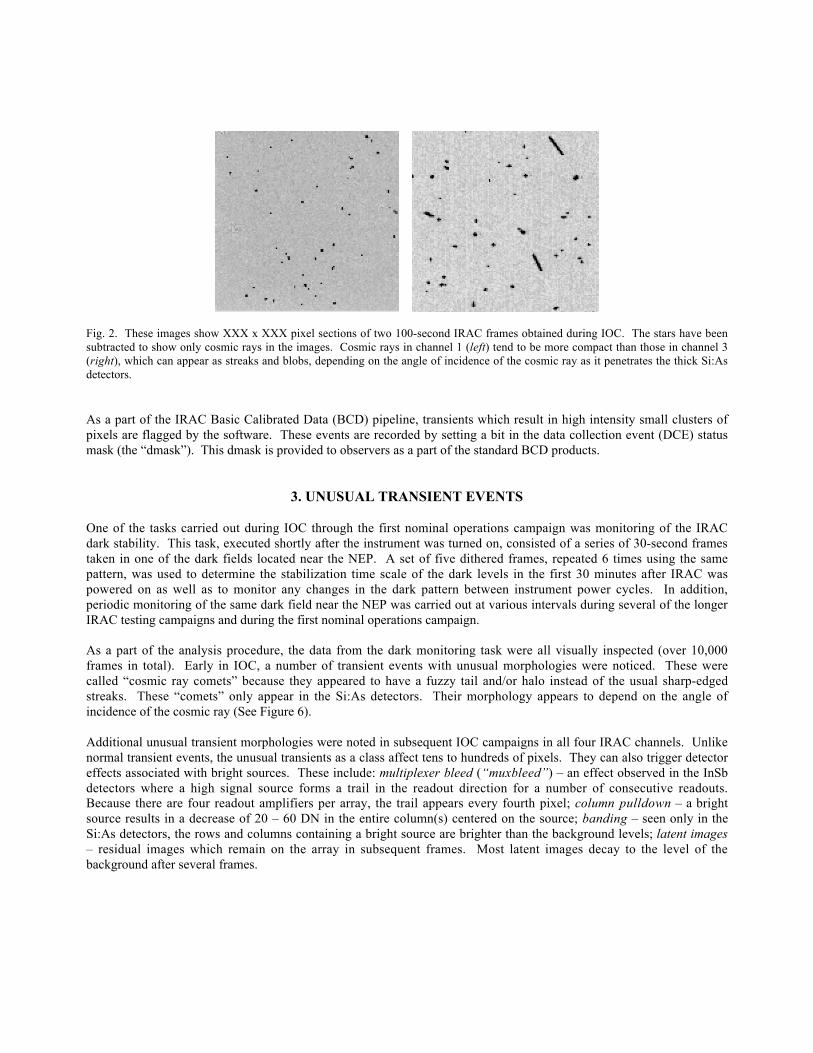
Fig. 2. These images show XXX x XXX pixel sections of two 100-second IRAC frames obtained during IOC. The stars have beensubtracted to show only cosmic rays in the images. Cosmic rays in channel 1 (left) tend to be more compact than those in channel 3(right), which can appear as streaks and blobs, depending on the angle of incidence of the cosmic ray as it penetrates the thick Si:Asdetectors.
As a part of the IRAC Basic Calibrated Data (BCD) pipeline, transients which result in high intensity small clusters ofpixels are flagged by the software. These events are recorded by setting a bit in the data collection event (DCE) statusmask (the “dmask”). This dmask is provided to observers as a part of the standard BCD products.
3. UNUSUAL TRANSIENT EVENTS
One of the tasks carried out during IOC through the first nominal operations campaign was monitoring of the IRACdark stability. This task, executed shortly after the instrument was turned on, consisted of a series of 30-second framestaken in one of the dark fields located near the NEP. A set of five dithered frames, repeated 6 times using the samepattern, was used to determine the stabilization time scale of the dark levels in the first 30 minutes after IRAC waspowered on as well as to monitor any changes in the dark pattern between instrument power cycles. In addition,periodic monitoring of the same dark field near the NEP was carried out at various intervals during several of the longerIRAC testing campaigns and during the first nominal operations campaign.
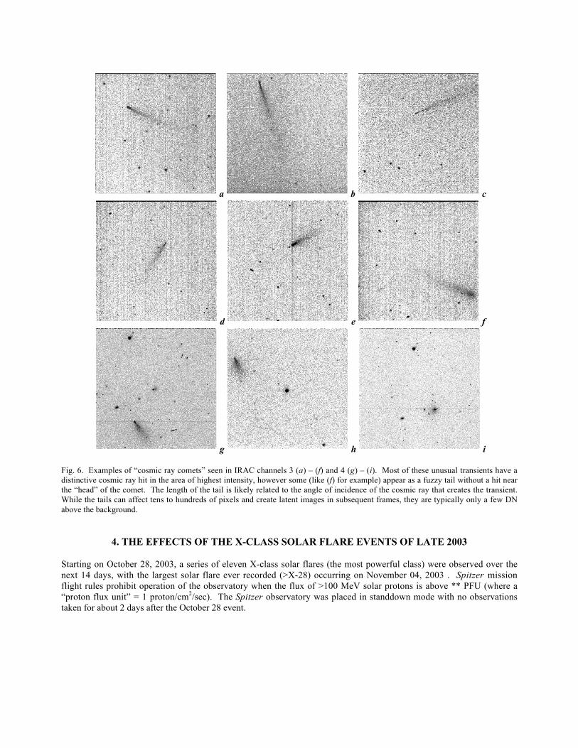
As a part of the analysis procedure, the data from the dark monitoring task were all visually inspected (over 10,000frames in total). Early in IOC, a number of transient events with unusual morphologies were noticed. These werecalled “cosmic ray comets” because they appeared to have a fuzzy tail and/or halo instead of the usual sharp-edgedstreaks. These “comets” only appear in the Si:As detectors. Their morphology appears to depend on the angle ofincidence of the cosmic ray (See Figure 6).
Additional unusual transient morphologies were noted in subsequent IOC campaigns in all four IRAC channels. Unlikenormal transient events, the unusual transients as a class affect tens to hundreds of pixels. They can also trigger detectoreffects associated with bright sources. These include: multiplexer bleed (“muxbleed”) – an effect observed in the InSbdetectors where a high signal source forms a trail in the readout direction for a number of consecutive readouts.Because there are four readout amplifiers per array, the trail appears every fourth pixel; column pulldown – a brightsource results in a decrease of 20 – 60 DN in the entire column(s) centered on the source; banding – seen only in theSi:As detectors, the rows and columns containing a bright source are brighter than the background levels; latent images– residual images which remain on the array in subsequent frames. Most latent images decay to the level of thebackground after several frames.
a b
c d
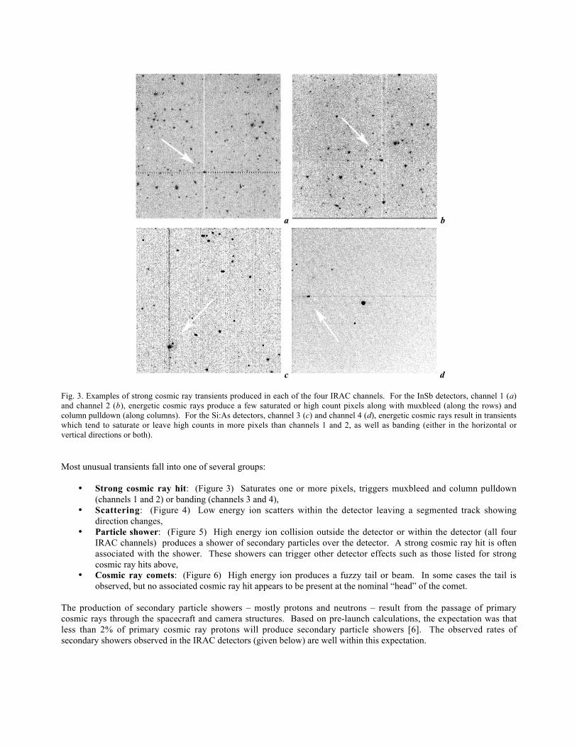
Fig. 3. Examples of strong cosmic ray transients produced in each of the four IRAC channels. For the InSb detectors, channel 1 (a)and channel 2 (b), energetic cosmic rays produce a few saturated or high count pixels along with muxbleed (along the rows) andcolumn pulldown (along columns). For the Si:As detectors, channel 3 (c) and channel 4 (d), energetic cosmic rays result in transientswhich tend to saturate or leave high counts in more pixels than channels 1 and 2, as well as banding (either in the horizontal orvertical directions or both).
Most unusual transients fall into one of several groups:
• Strong cosmic ray hit: (Figure 3) Saturates one or more pixels, triggers muxbleed and column pulldown(channels 1 and 2) or banding (channels 3 and 4),
• Scattering: (Figure 4) Low energy ion scatters within the detector leaving a segmented track showingdirection changes,
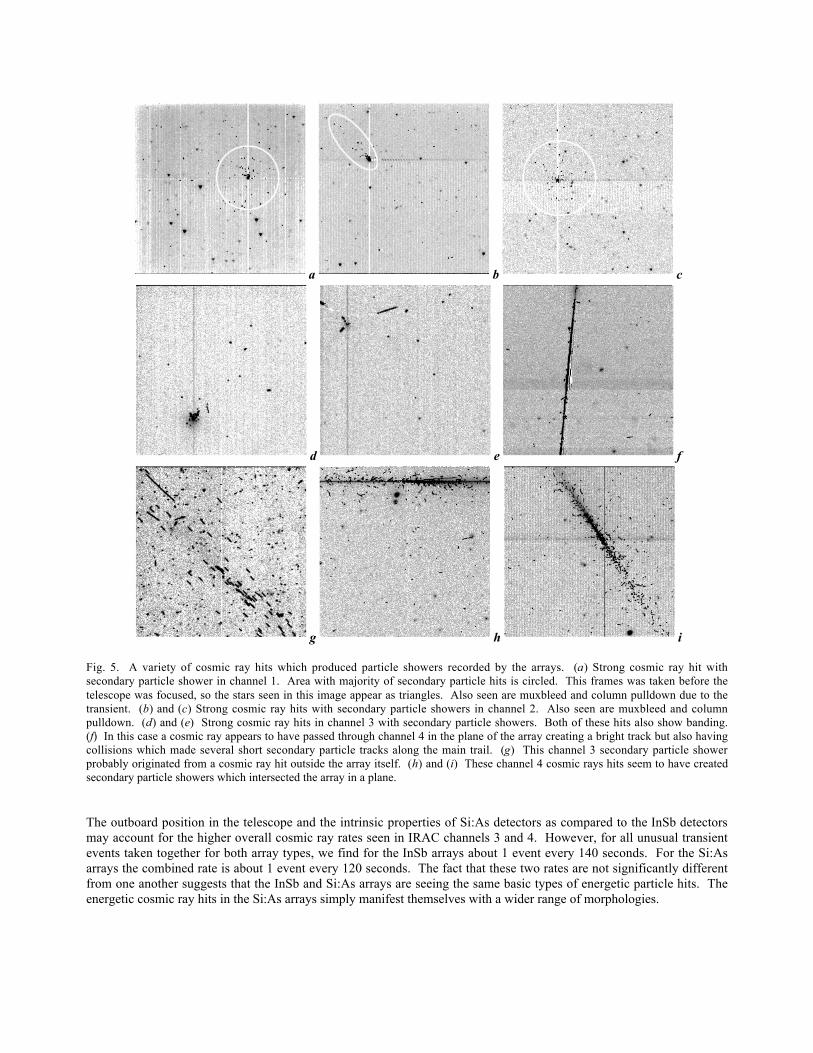
• Particle shower: (Figure 5) High energy ion collision outside the detector or within the detector (all fourIRAC channels) produces a shower of secondary particles over the detector. A strong cosmic ray hit is oftenassociated with the shower. These showers can trigger other detector effects such as those listed for strongcosmic ray hits above,
• Cosmic ray comets: (Figure 6) High energy ion produces a fuzzy tail or beam. In some cases the tail isobserved, but no associated cosmic ray hit appears to be present at the nominal “head” of the comet.
The production of secondary particle showers – mostly protons and neutrons – result from the passage of primarycosmic rays through the spacecraft and camera structures. Based on pre-launch calculations, the expectation was thatless than 2% of primary cosmic ray protons will produce secondary particle showers [6]. The observed rates ofsecondary showers observed in the IRAC detectors (given below) are well within this expectation.

a b
c d
Fig. 4. Examples of lower energy cosmic rays undergoing scattering within the Si:As arrays producing tracks with unusual shapes.(a) Channel 4 U-shaped track resulting from at least two scattering events. (b) Channel 3 apparently curved track due to at least twoscattering events. (c) Check-mark shaped track in channel 4. (d) This unusual set of tracks in channel 3 was likely produced by thesame cosmic ray as it scattered back and forth in the plane of the detector crossing through different layers of the device.
The effect in the Si:As detectors that allows the cosmic ray comets to be produced is not fully understood at this time.The passage of a cosmic ray through an electric field free region in the detector produces a cloud of liberated chargecarriers which then diffuse until some of them enter a layer with an electric field where they are then driven across theinfrared active region where to be collected by the contacts. Some evidence in the test data suggest this particularmorphology disappears entirely or is greatly reduced after annealing of the channel 3 and 4 FPAs. That is, heating thearrays above their nominal operating temperatures to remove hot pixels or residual images. At the end of IOC, a testwas conducted on annealing strategy in the middle of an IRAC campaign. The success of this test led to regularannealing being implemented as a part of the IRAC power on sequence. Since this first annealing test, cosmic raycomets have not been observed in subsequent IRAC dark monitoring tests.
For channels 1 and 2 (InSb), the combined mean rate over all campaigns for strong cosmic ray hits is 7.3x10⁻³ persecond, or about 1 event every 140 seconds. Particle shower events occur at a rate of 2.6x10⁻⁴ per second or about 1such event per hour. For channels 3 and 4 (Si:As), the combined mean rate of strong cosmic ray hits over all campaignsis 5.0x10⁻³ per second or about 1 event every 200 seconds. For cosmic ray comets, the overall combined rate is 3.3x10⁻³
per second or about 1 event every 300 seconds. For particle shower events the rate is 5.8x10⁻⁴ per second or about 1event every 30 minutes. Particle shower events may be more common in the Si:As detectors because the relativethickness of these detectors compared to the InSb arrays may make them more sensitive to a wider range of angles ofincidence for these events.
a b c
d e f
g h i
Fig. 5. A variety of cosmic ray hits which produced particle showers recorded by the arrays. (a) Strong cosmic ray hit withsecondary particle shower in channel 1. Area with majority of secondary particle hits is circled. This frames was taken before thetelescope was focused, so the stars seen in this image appear as triangles. Also seen are muxbleed and column pulldown due to thetransient. (b) and (c) Strong cosmic ray hits with secondary particle showers in channel 2. Also seen are muxbleed and columnpulldown. (d) and (e) Strong cosmic ray hits in channel 3 with secondary particle showers. Both of these hits also show banding.(f) In this case a cosmic ray appears to have passed through channel 4 in the plane of the array creating a bright track but also havingcollisions which made several short secondary particle tracks along the main trail. (g) This channel 3 secondary particle showerprobably originated from a cosmic ray hit outside the array itself. (h) and (i) These channel 4 cosmic rays hits seem to have createdsecondary particle showers which intersected the array in a plane.
The outboard position in the telescope and the intrinsic properties of Si:As detectors as compared to the InSb detectorsmay account for the higher overall cosmic ray rates seen in IRAC channels 3 and 4. However, for all unusual transientevents taken together for both array types, we find for the InSb arrays about 1 event every 140 seconds. For the Si:Asarrays the combined rate is about 1 event every 120 seconds. The fact that these two rates are not significantly differentfrom one another suggests that the InSb and Si:As arrays are seeing the same basic types of energetic particle hits. Theenergetic cosmic ray hits in the Si:As arrays simply manifest themselves with a wider range of morphologies.
a b c
d e f
g h i
Fig. 6. Examples of “cosmic ray comets” seen in IRAC channels 3 (a) – (f) and 4 (g) – (i). Most of these unusual transients have adistinctive cosmic ray hit in the area of highest intensity, however some (like (f) for example) appear as a fuzzy tail without a hit nearthe “head” of the comet. The length of the tail is likely related to the angle of incidence of the cosmic ray that creates the transient.While the tails can affect tens to hundreds of pixels and create latent images in subsequent frames, they are typically only a few DNabove the background.
4. THE EFFECTS OF THE X-CLASS SOLAR FLARE EVENTS OF LATE 2003
Starting on October 28, 2003, a series of eleven X-class solar flares (the most powerful class) were observed over thenext 14 days, with the largest solar flare ever recorded (>X-28) occurring on November 04, 2003 . Spitzer missionflight rules prohibit operation of the observatory when the flux of >100 MeV solar protons is above ** PFU (where a“proton flux unit” = 1 proton/cm2/sec). The Spitzer observatory was placed in standdown mode with no observationstaken for about 2 days after the October 28 event.
Cosmic Ray Statistics
0
2
4
6
8
10
12
14
9/14/03 10/12/03 11/9/03 12/7/03 1/4/04 2/1/04 2/29/04 3/28/04 4/25/04 5/23/04
Date of Observation
Nu
mb
er o
f p
ixel
s/se
c
Ch 1
Ch 2
Ch 3
Ch 4
Fig. 7. Total cosmic ray rates for each IRAC channel for all campaigns from IOC just after launch through April 2004. The elevatedrates during a relatively quiescent period following a series of X-class solar flares in late October 2003 are seen as the sharp peak inthis plot. During the flares, IRAC was powered off.
IRAC was last powered on about a week before the October 28 flare, when the solar proton levels were about 0.02 PFU.IRAC was already powered off when the highest proton flux from the flares on October 28 occurred. IRAC waspowered-on for a pair short campaigns on October 31 and November 03 designed to evaluate the instrumentperformance and to anneal the detectors to fix radiation-damaged pixels. During these flare recovery campaigns, thesolar proton levels were within operating limits but were above normal at values of 0.2 – 3 PFU. The next “nominal”IOC campaign began late on November 04, just before the large solar flare of that date. Because this flare was mainlydirected away from the Earth and Spitzer, no major effects were seen.
During the flare recovery campaigns, the total cosmic ray rates were about a factor of two higher than in the pre-flareoperations period (Figure 7). It was not possible to evaluate the rate of unusual transients since only a limited set oftasks were run in the very short flare recovery campaigns. In the nominal IOC campaign that began on November 04,there was no convincing evidence in the dark stability monitoring data of any elevated rates in unusual transient events.The main effects of the solar flare on IRAC was an increase in the number of isolated hot pixels - 9, 6, 0, and 50 newhot pixels in IRAC channels 1 – 4 respectively compared to 35, 18, 0, and 1 total hot pixels before the flares. It isunknown if this change in the number of hot pixels is permanent as they have survived several anneals and powercycles. No changes were seen to the number of dead or isolated low response pixels. No change was seen to IRACsensitivity in any channel. We found that at rates of >1 PFU the increased cosmic ray rate was significant on the IRACdetectors and we conclude that we would not be able to perform science observations at rates above 2 PFU even if itwas deemed safe to run IRAC from an operational standpoint.

5. TRANSIENT MITIGATION STRATEGY
The best strategy to mitigate transient event effects in IRAC images is to use sufficient redundancy in the number ofexposures made in the area of the target of interest. That is, when planning their astronomical observation request(AOR), observers should ensure that multiple exposures are made at the same sky coordinates, either by repeatedexposures or dithering the telescope around the target position, or a combination of both methods, in order to allow forthe removal of transient events in later processing. If using IRAC in a mapping mode, the observer can, in addition tothe other strategies, plan the AOR such that sufficient overlap is made with adjacent map positions to have redundancyin sky coordinates.
The Spitzer Science Center (SSC) mosaicer software [7] is designed to perform effective detection and masking of thetransient events, a.k.a. outlier detection, where outliers are defined as moving objects and cosmic ray hits in the inputimages. The mosaicer performs outlier detection in interpolated images projected to a common grid. Two algorithmsare implemented in the mosaicer which take advantage of the redundant information in the overlap areas of theindividual frames. The first – multi-frame temporal outlier detection – is best used when there are many input imagesavailable for a particular area (Figure 8). At each grid position n-sigma clipping is done for the stack of individual inputpixels for that position in the time domain. The second approach – dual outlier detection – has been designed to dealwith areas of shallow coverage in terms of individual images (Figure 9). Here two-stage filtering is performed. Thefirst stage is spatial filtering, whereupon spatial objects - clusters of pixels above a user-specified threshold - aredetected in each frame. In the second stage the spatial objects in the interpolated images are matched in the timedomain. The unmatched objects are declared outliers and are excluded from the final mosaic. While the SSCautomated pipeline doesn’t perform dual outlier detection as a part of producing the standard pipeline data products, thisalgorithm is included in the offline version of the mosaicer software (called mopex) and can be exploited by users,especially for observations with shallow redundancy. The results of the multiframe temporal and dual outlier rejectionalgorithms are recorded in the “rmask” file produced by the software, which also contains information about singleframe outlier detection copied from the dmask.
Fig. 8. Before (left) and after (right) images of an IRAC channel 4 mosaic for data with a depth coverage of 16 individual exposuresshowing the ability of the SSC mosaicer to clean final mosaic of transient events using standard multi-frame outlier rejection. Theimages shown are 375 x 316 IRAC pixels in dimension.

Fig. 9. Example showing the effectiveness of the SSC mosaicer on removing a cosmic ray from IRAC channel 3 data with just adepth coverage of 2 images. The images shown are 69 x 72 IRAC pixels, before (left) and after (right) the correction.
ACKNOWLEDGEMENTS
The authors would like to thank Rick Arendt, Jason Surace, and Bill Glaccum (Spitzer Science Center) for additionalcontributions to this paper. This work is based on observations made with the Spitzer Space Telescope, which isoperated by the Jet Propulsion Laboratory, California Institute of Technology under NASA contract 1407. Support forthe IRAC instrument was provided by NASA under contract number 960541 issued by JPL.
REFERENCES
1. Fazio, G. G. et al. 2004. “The Infrared Array Camera (IRAC) for the Spitzer Space Telescope”, ApJS Special Spitzerissue
2. IRAC - Infrared Array Camera on the Spitzer Space Telescope (http://cfa-www.harvard.edu/irac)3. Spitzer Science Center, Observatory & Science Instruments: IRAC (http://ssc.spitzer.caltech.edu/irac)4. Garcia, M. D. 2004, "SIRTF Takes Flight," Paper AAS 04-225, Maui, Hawaii, Feb 8-12, 20045. Romano, E. 1996. “Radiation Transport Through the SIRTF Observatory for the External Environment to the Focal
Plane”, IRAC/SDT96-8026. Kong, R. 1998. “Secondary Particle Radiation Analysis”, IRAC/TM98-60017. Spitzer Mosaicer User’s Guide (http://ssc.spitzer.caltech.edu/postbcd/doc/mosaicer.pdf)