normarc 7000b - indra · indra navia as (head office) olaf helsets vei 6 p.o. box 150 oppsal...
TRANSCRIPT

NORMARC 7000 ILS systems are available in a wide range of configurations all meeting the most stringent ICAO Level 4 requirements and designed to be cost-effective, easy to install and operate, and above all, dependable.
NORMARC 7000B Instrument Landing System
NORMARC 7000 INSTRUMENT LANDING SYSTEM (ILS) LOCALIZER GLIDE PATH
SYSTEM
Coverage — course — clearance
25NM/±10° 17NM/±35°
10NM/±8° azimuth
Course width 2° to 6° adjustable ± 0.24 x glide path angle
Glide path angle — 2° to 4° adjustable
Course stability < ± 1m (typical) < ± 0.04°
TRANSMITTER
Frequency range 108 to 112 MHz 328.6 to 335.4 MHz
Frequency tolerance ± 0.0004% ± 0.0004%
Output power CSB (Course and Clearance) 5 - 25W adjustable (Course/Clearance) 3 - 8W adjustable (Course) 0.3 – 1W adjustable (Clearance)
Modulation depth 90/150 Hz nominal 20% 40%
Adjustable range (each tone) 10-25% 10-44%
Frequency tolerance (90/150 Hz) ± 0.01% ± 0.01%
Total harmonic distortion (90/150 Hz) 1% maximum 1% maximum
Phase locking (90 Hz to 150 Hz) 5° maximum ref 150 Hz 5° maximum ref 150 Hz
CSB/SBO adjustment range 360° 360°
IDENTITY KEYER
Modulation Frequency 1020 Hz ± 0.5 Hz
Modulation depth 5 - 15% adjustable
Built- in interface for DME co-location, ILS can be ident master or slave
MONITORING
Alarm parameter (selectable) Integral course line Integral displacement sensitivity Near- field course line Integral clearance (two frequency only)
Identity
Integral Glide path angle Integral displacement sensitivity Near field Glide path angle Integral clearance (two frequency only)
Total period of radiation out of tolerance 1 to 10 seconds 1 to 6 seconds
Additional near- field time delay 0 to 20 seconds 0 to 20 seconds
AIR TRAFFIC MANAGEMENT
Indra Navia AS (head office)Olaf Helsets vei 6P.O. Box 150 OppsalNO-0619 Oslo, NorwayT: (+47) 23 18 02 00F: (+47) 23 18 02 [email protected]
Indra reserves the right tomodify these specificationswithout prior notice.
Indra Navia ASBromsveien 17P.O. Box 145NO-3191 Horten, NorwayT (+47) 23 18 02 00F (+47) 23 12 37 [email protected]
NORMARC 7000B Instrument Landing System
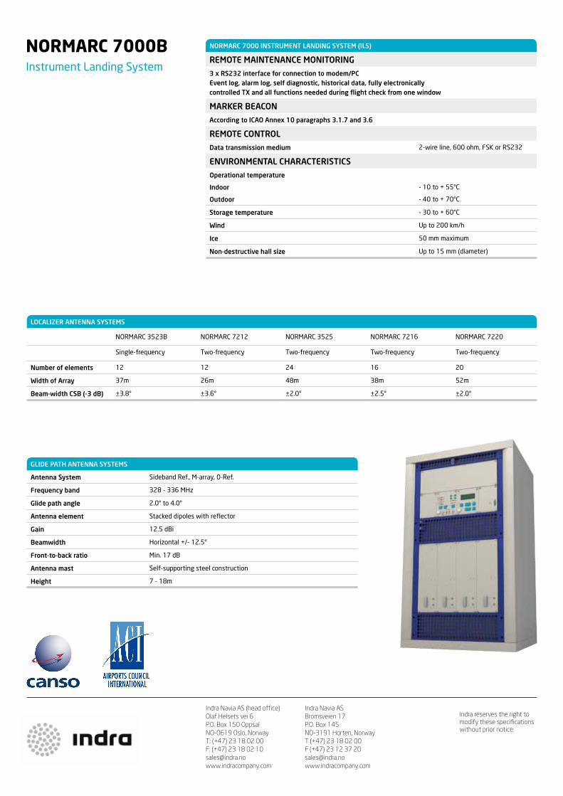
LOCALIZER ANTENNA SYSTEMS
NORMARC 3523B NORMARC 7212 NORMARC 3525 NORMARC 7216 NORMARC 7220
Single-frequency Two-frequency Two-frequency Two-frequency Two-frequency
Number of elements 12 12 24 16 20
Width of Array 37m 26m 48m 38m 52m
Beam-width CSB (-3 dB) ±3.8° ±3.6° ±2.0° ±2.5° ±2.0°
GLIDE PATH ANTENNA SYSTEMS
Antenna System Sideband Ref., M-array, 0-Ref.
Frequency band 328 - 336 MHz
Glide path angle 2.0° to 4.0°
Antenna element Stacked dipoles with reflector
Gain 12.5 dBi
Beamwidth Horizontal +/- 12.5°
Front-to-back ratio Min. 17 dB
Antenna mast Self-supporting steel construction
Height 7 - 18m
NORMARC 7000 INSTRUMENT LANDING SYSTEM (ILS)
REMOTE MAINTENANCE MONITORING
3 x RS232 interface for connection to modem/PC Event log, alarm log, self diagnostic, historical data, fully electronically controlled TX and all functions needed during flight check from one window
MARKER BEACON
According to ICAO Annex 10 paragraphs 3.1.7 and 3.6
REMOTE CONTROL
Data transmission medium 2-wire line, 600 ohm, FSK or RS232
ENVIRONMENTAL CHARACTERISTICS
Operational temperature
Indoor
Outdoor
- 10 to + 55°C
- 40 to + 70°C
Storage temperature - 30 to + 60°C
Wind Up to 200 km/h
Ice 50 mm maximum
Non-destructive hall size Up to 15 mm (diameter)

Easy installation and flexible connections make it an ideal companion to ILS equipment. The receiver unit is selfcontained for mounting in a shelter. It is typically located between threshold and the Middle Marker site with monitor antenna(s).
Two receivers are included in the receiver unit as standard; one is for Course Line (CL) monitoring and the other is (at the customer’s option) used for Course Sector (CS) monitoring.
The receiver unit receives and processes the ILS signal to provide information on DDM, SDM, and RF level for both channels.
The ILS signal information is transmitted either to a NORMARC 7000 ILS, or to a connected PC with control software, normally located inside the radio equipment room, usually through external modems.
NORMARC 7720Far Field Monitor
AIR TRAFFIC MANAGEMENT
The NORMARC 7720 ILS Far Field Monitor (FFM) is an accurate, reliable and user-friendly piece of equipment.

Indra Navia AS (head office)Olaf Helsets vei 6P.O. Box 150 OppsalNO-0619 Oslo, NorwayT: (+47) 23 18 02 00F: (+47) 23 18 02 [email protected]
Indra reserves the right tomodify these specificationswithout prior notice.
Indra Navia ASBromsveien 17P.O. Box 145NO-3191 Horten, NorwayT (+47) 23 18 02 00F (+47) 23 12 37 [email protected]
NORMARC 7720Far Field Monitor
NORMARC 7720
SPECIFICATIONS
Frequency range* 108.1-111.95 MHz
Channel spacing 50 kHz
RF level range 0 dBm to -80 dBm
DDM range 0-40%
DDM
Centring
Deviation
0.07% DDM
0.07% DDM
± 1.25% of DDM-reading
SDM range 0-95%
SDM error 0.5% SDM
Input connectors 2 BNC female
Output connectors Ethernet RJ45 RS-232
User Interface Graphical colour 5.7” LCD Keys for selecting function and parameter
Power input 115VAC or 230VAC nominal voltage
Internal battery capacity 4 hours (12V)
Dimensions (WxHxD) 400 x 500 x 220 mm
Weight 19 kg
Antenna type 2-element Yagi
Antenna mast height Typically 6 m
Antenna cable 50Ω coaxial
Temperature range, operating -10° to +50°C
* The FFM includes GP receivers in addition to Localizer receivers, hence, it can also be used for Glide Path monitoring
NORMARC 7720
CONFIGURATION 2 (PC can handle 2 runway ends)
CONFIGURATION 1 Can be extended to include the data logger SW by adding a pair of modems and a PC (option at additional cost)
MODEM NORMARC 7000 ILS
PC (OPTIONAL) WITH DATA LOGGER SW
ILS RCUFFM
STATUS PANEL
FFM STATUS PANEL
MODEM
BATTERY
FFM RECEIVERCL
CS
PSU
Not part of NORMARC 7720
Part of NORMARC 7720
delivery
Typical ILS setup with connected NORMARC 7720 Far Field Monitor
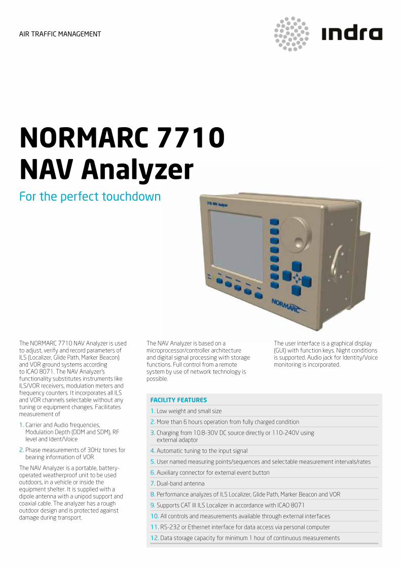
The NORMARC 7710 NAV Analyzer is used to adjust, verify and record parameters of ILS (Localizer, Glide Path, Marker Beacon) and VOR ground systems according to ICAO 8071. The NAV Analyzer’s functionality substitutes instruments like ILS/VOR receivers, modulation meters and frequency counters. It incorporates all ILS and VOR channels selectable without any tuning or equipment changes. Facilitates measurement of
1. Carrier and Audio frequencies, Modulation Depth (DDM and SDM), RF level and Ident/Voice
2. Phase measurements of 30Hz tones for bearing information of VOR
The NAV Analyzer is a portable, battery-operated weatherproof unit to be used outdoors, in a vehicle or inside the equipment shelter. It is supplied with a dipole antenna with a unipod support and coaxial cable. The analyzer has a rough outdoor design and is protected against damage during transport.
The NAV Analyzer is based on a microprocessor/controller architecture and digital signal processing with storage functions. Full control from a remote system by use of network technology is possible.
The user interface is a graphical display (GUI) with function keys. Night conditions is supported. Audio jack for Identity/Voice monitoring is incorporated.
NORMARC 7710 NAV AnalyzerFor the perfect touchdown
FACILITY FEATURES
1. Low weight and small size
2. More than 6 hours operation from fully charged condition
3. Charging from 10.8-30V DC source directly or 110-240V using external adaptor
4. Automatic tuning to the input signal
5. User named measuring points/sequences and selectable measurement intervals/rates
6. Auxiliary connector for external event button
7. Dual-band antenna
8. Performance analyzes of ILS Localizer, Glide Path, Marker Beacon and VOR
9. Supports CAT III ILS Localizer in accordance with ICAO 8071
10. All controls and measurements available through external interfaces
11. RS-232 or Ethernet interface for data access via personal computer
12. Data storage capacity for minimum 1 hour of continuous measurements
AIR TRAFFIC MANAGEMENT
Indra Navia AS (head office)Olaf Helsets vei 6P.O. Box 150 OppsalNO-0619 Oslo, NorwayT: (+47) 23 18 02 00F: (+47) 23 18 02 [email protected]
Indra reserves the right tomodify these specificationswithout prior notice.
Indra Navia ASBromsveien 17P.O. Box 145NO-3191 Horten, NorwayT (+47) 23 18 02 00F (+47) 23 12 37 [email protected]
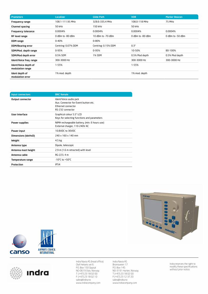
Prameters Localizer Glide Path VOR Marker Beacon
Frequency range 108.1-111.95 MHz 328.6-335.4 MHz 108.0-118 MHz 75 MHz
Channel spacing 50 kHz 150 kHz 50 kHz
Frequency tolerance 0.0004% 0.0004% 0.0004% 0.0004%
RF level range 0 dBm to -80 dBm 10 dBm to -70 dBm 0 dBm to -80 dBm 0 dBm to -50 dBm
DDM range 0-40% 0-80%
DDM/Bearing error Centring: 0.07% DDM Centring: 0.15% DDM 0.3°
SDM/Mod. depth range 0-95% 0-95% 10-50% 80-100%
SDM/Mod depth error 0.5% SDM 1% SDM 0.5% Mod depth 0.5% Mod depth
Ident/Voice freq. range 300-3000 Hz 300-3000 Hz 300-3000 Hz
Ident/Voice depth of modulation range
1-55% 1-55%
Ident depth of modulation error
1% mod. depth 1% mod. depth
Input connectors BNC female
Output connector Ident/Voice audio-jack Aux. Connector for Event button etc. Ethernet connector RS-232 connector
User Interface Graphical colour 5.5” LCD Keys for selecting functions and parameters
Power supplies NiMH rechargeable battery, (min. 6 hours use) External charger, 110-240V AC
Power input 10.8VDC to 30VDC
Dimensions (WxHxD) 240 x 160 x 140 mm
Weight 4.5 kg
Antenna type Dipole, telescopic
Antenna mast height 2.9 m (1.6 m retracted) with level
Antenna cable RG-223, 4 m
Temperature range -10°C to +50°C
Protection IP54

NORMARC 8100 Ground Based Augmentation System
One physical rack can provide service to several runways and runway ends, with several approach patterns for each runway end, and provides azimuth, elevation and distance guidance in one system. Siting flexibility and reduced requirements to flight inspection makes GBAS a cost effective alternative for the future.
The NORMARC 8100 GBAS System is designed to meet the ICAO Annex 10 requirements currently under development for CAT II/III conditions, and Eurocae ED-114 for CAT I conditions. It is a single constellation (GPS) single frequency system. The robust design is based on decades of experience with Instrument Landing Systems and Special Category I GPS-based landing systems.
The NORMARC 8100 provides a flexible architecture and user friendly interfaces developed through close cooperation with users of our other landing systems. The system allows up to four GPS receivers and up to four VHF transmitters/receivers, where two of the four sets can be located on a remote location to accommodate sites where VHF coverage is challenging. The architecture is selected from a safety and security perspective, aiding operational approval.
AIR TRAFFIC MANAGEMENT
GBAS is a new satellite based landing system which can provide significant capacity, efficiency, safety and environmental benefits for airlines, airports and air navigation service providers.
Indra Navia participates in SESAR in order to define and develop concepts and systems for the Single European Sky. GBAS CAT II/III is one of these concepts.

Indra Navia AS (head office)Olaf Helsets vei 6P.O. Box 150 OppsalNO-0619 Oslo, NorwayT: (+47) 23 18 02 00F: (+47) 23 18 02 [email protected]
Indra reserves the right tomodify these specificationswithout prior notice.
Indra Navia ASBromsveien 17P.O. Box 145NO-3191 Horten, NorwayT (+47) 23 18 02 00F (+47) 23 12 37 [email protected]
NORMARC 8100 GROUND BASED AUGMENTATION SYSTEM (GBAS)
TRANSMITTER
Frequency Range 108 – 117.975 MHz
Output Power Range 20 — 80 W
Coverage:
Laterally
Vertically
28 km ± 35°, 37 km ± 10°
0,75 – 7°
ENVIRONMENTAL CHARACTERISTICS
Operational Temperature:
Indoor
Outdoor
-10 – 50 °C
-40 – 55 °C
Humidity:
Indoor
Outdoor
95% below 35 deg
60% above 35 deg
95% below 35 deg
60% above 35 deg
Rain 100 mm/h
Icing 50 mm
Wind 130 km/h
Solar radiation 1120W/m2
ACCURACY
Range Accuracy ED-114 GAD C
Position Accuracy ICAO Annex 10 (16m horizontally and 4 m vertically 95%)
BATTERY BACKUP
Battery Operation 3 – 30 h depending on # of transmitters, output power and duty cycle
PHYSICAL CHARACTERISTICS
Power Consumption 400-2000 W depending on # of transmitters, output power and duty cycle
Dimensions (HxWxD) 1020x600x550
Weight 100-110 kg depending on configuration, excluding battery bank and antennas
REMOTE CONTROL
Data transmission medium 2-wire lined, 600 ohm, FSK or RS-232
MAINTENANCE & MONITORING
PC-based over Ethernet local or remote, for configuration, alarm log, diagnostics, validation
RECORDING
In-rack one week of legal recording
NORMARC 8100Ground Based Augmentation System

DOPPLER VHFOMNIDIRECTIONALRANGE
AIR TRAFFIC MANAGEMENT
indracompany.com
Supplying ATM systems around the world for more than 90 years

AIR TRAFFIC MANAGEMENT DOPPLER VHFOMNIDIRECTIONALRANGE
AIR TRAFFIC MANAGEMENT
Introduction
The Indra DVOR is the ultimate choice in Doppler VHF Omnidirectional Range equipments combining quality with exceptional value for money.
The equipment employs state of the art technology ensuring high reliability in order to meet the demands of both civil and military requirements.
Fundamental to the design concept of this unit are integrity, reliability, and maintainability.
The equipment has been tested under the most demanding environmental conditions, allowing equipment operation in any environment.
The Indra DVOR is an easy to use system requiring minimal maintenance.
That meets or exceeds all requirements of ICAO ANNEX 10, VOLUME I EDITION 6, and EUROCAE ED-52, enabling interoperability with all currently available radio navigation aids on the market.
This equipment is another exceptional result of Indras’ expertise in radio navigation aids.
A low cost and highly reliable equipment readyfor the most severe climatic conditions
DVOR-DME Antenna at Ipiales - Colombia in 2011

AIR TRAFFIC MANAGEMENT
DVOR LCU Screen
Situation Data Display 2KCharacteristicsMONITORConfiguration FrequencyMonitor voting Alarm thresholds
Carrier power Bearing information Reduction in modulation depth
or 30 Hz AMor Sub-carrier 30 Hz FM or Ident
Ident code Antenna monitoring
Monitor failureAntenna sensors
VOICE INPUT FACILITIESMicrophone input Line input - analog Digital input Voice compandorENVIRONMENTALTemperature
Relative Humidity
Maximum altitude
Wind
Hail/Ice
Single/dual108 MHz to 118 MHzAND/ORDigitally configurable3dB ± 1dB, adjustable± 1º maximum, adjustable
15% ± 1%, adjustable15% ± 1%, adjustable50% ± 10%, adjustableContinuous / Absence of tone, Incorrect CodeIndividual antennasDiametrically opposite antenna pairs Three individual antennas failure.YesNFM and FFM (Yagi or dipole antenna)
-52 dBm to -9 dBm @ 600 ohm-37 dBm to +6 dBm @ Balanced 600 ohmOptical S/PDIF In/Out Toslink User selectable
-20ºC to +60ºC Indoor-50ºC to + 70ºC Outdoor95% Indoor100% Outdoor15,000 ft operating45,000 ft inoperative160 km/h operating200 km/h survival50 mm

AIR TRAFFIC MANAGEMENT
Indra DVOR
The equipment is an state-of-the-art technology product ensuring high reliability and maintainability based on many years of operation in fielded systems in order to meet the demands of both civil and military requirements.
The system is a low-cost and high performance turn-key solution with high flexibility to be adapted, if required to customers sites and/or maintenance communications architecture necessities.
The system makes use of the experience gained by Indra in developing and installing navaid systems for clients in a wide variety of countries world wide under the most severe climatic conditions.
• Dual transmitters, monitors, power supplies and control
• RF amplifiers modules based on solid state technology
• Multiple interfaces (RS-232, Ethernet, etc.)• Extense use of latest digital technology• Friendly and intuitive user interface• Multiple configurations • Standard and flexible RMM architecture• High level BITE
Main characteristics
The main and most advanced feature of the INDRA DVOR is its high reliability.
The System is available in two options, single, and dual DVOR configuration, both employing the use of high quality electronic components.
The equipment has a modern and modular design which performs continuous monitoring of the main system parameters, providing high reliability and availability rates.
Provides extensive use of digital technology and a powerful monitoring and BIT processes in addition a global connectivity providing multiple interfaces according the customer requirements.
Technology
The INDRA DVOR is based on a modular design architecture, solid state components and auto-diagnosis Built In Test (BIT) concept to provide a superior level of reliability.
Direct digital synthesizer (DDS) techniques are used for timing, frequency and waveform generation circuitry, derived from a single stable temperature-compensated crystal clock circuit which ensures accurate clocking of all critical time-dependent pulse generation and measurement circuits.
The equipment can be integrated with a versatile and robust software architecture that allows control and supervision performed locally or remotely, with several security levels.
The software architecture is based on standard protocols which provide intuitive and simple operation.
There are available different interfaces such as Ethernet, RS-232 and RS-485 allowing system compatibility and remote control connections accomplished by multiple means including dial-up modem, leased-lines, radio, IP-based virtual private network (VPN), Ethernet, and cellular networks.
Includes a Built In Test (BIT) capability designed to detect, isolate and report any malfunction or condition out of tolerance by using automatic and non-interruptive self-tests down to LRU level.
These BIT (Built In Test) system capabilities reduce dramatically routine maintenance tasks and repair times, allowing the chance of predicting a degradation of system performances. The results of the BITE process are available both local and remotely via L/RMM.
The maintenance concept is based on LRU modules, easily accessible and exchangeable.
All components of the INDRA DVOR have been selected to provide maximum reliability and minimize maintenance costs.
RMM Maintenance and reliability

AIR TRAFFIC MANAGEMENT
DVOR Equipment
Double side band DVORSingle or Dual25 W to >100 W adjustable in 0.1 W steps108 to 117.95 MHz50 KHz channel± 5ppmDigitally programable by Syntheziser± 0.5º± 180º in 0.01º steps<-70 dBc typically1 + 48 alford loopsHorizontalFull local and remote indicationYesComplete system / LRU monitoringEthernet / RS-232 and RS-485MTBF > 10,000 h (single)MTBO > 20,000 h (dual)MTTR < 30 m (15m typical)650 VA (single) 750 VA (warm standby)One19” standard rack (33u):600 x 600 x 1467 mm (WxDxH)
30 Hz ± 5 ppm28% to 32% digitally adjustable5%<3% of fundamentalInternational morse up to 5 chars1020 Hz ± 5 ppm0 to 20% digitally adjustable6 times per min., adjustableIndependent/Associated
300 Hz to 3000 Hz0% to 40% digitally adjustable>30 dB
9960 Hz ± 5 ppm28% to 32% digitally adjustable16 ± 1Better than ICAO and ED-52± 9960 Hz, reference 0 dB2nd harmonic < -40 dBc3rd harmonic < - 50 dBc4th and above < - 60 dBc
Situation Data Display 2KCharacteristicsGENERAL CHARACTERISTICSType Configuration Output power Frequency rangeChannel spacing Carrier frequency stabilityOperating frecuency Bearing accuracyBearing AdjustmentSpurious RadiationAntenna systemPolarizationStatus indication Module hot replacementSystem monitoring (BITE) Local/remote interfaceReliability
Power ConsumptionDimensions
MODULATION SIGNAL CHARACTERISTICSReference phase
Frequency Modulation depth Distortion FactorHarmonic Distortion
Ident codeModulation frequency Modulation depthRepetition rate Operation mode
Voice ModulationFrequency rangeModulation depthNoise (due signal conmutation)
Variable phaseFrequencyMean depth FM modulation index Sideband harmonic levels

DISTANCEMEASURINGEQUIPMENT
AIR TRAFFIC MANAGEMENT
indracompany.com
Supplying ATM systems around the world for more than 90 years

AIR TRAFFIC MANAGEMENT DISTANCEMEASURINGEQUIPMENT
AIR TRAFFIC MANAGEMENT
Introduction
The Indra DME is the ultimate choice in Distance Measuring Equipment combining quality with exceptional value for money.
The equipment employs state-of-the-art technology ensuring high reliability in order to meet the demands of both civil and military requirements.
Integrity, reliability and maintainability are fundamental to the design concept of this system.
The equipment has been tested under the most demanding environmental conditions, ensuring equipment operation in any environment.
The Indra DME is an easy to use system requiring minimal maintenance, that meets or exceeds all requirements of ICAO annex 10, volume I edition 6, and EUROCAE ED-57, this enables interoperability with all currently available radio navigation aids on the market.
The result of Indra’s expertise in radio navigationis a new distance measuring equipment highlyreliable and low cost
DME Antenna

AIR TRAFFIC MANAGEMENT
SystemConfiguration
Standard Compliance
Aircraft Handling Capacity
Design
Module Hot Replacement
Status Indication
System Monitoring (BITE)
Remote/Local Control Interface
Environmental Conditions
Reliability
Power Consumption
Dimensions
Single or DualICAO Annex 10ICAO Doc 8071,EUROCAE ED-57RCM & CE Marking> 200 InterrogatorsFull solid-state and modularYesFull Local and Remote indicationComplete System & LRU Monitoring based on HWEthernet (RS-232 & RS-485)Operating Temperature:• -20ºC to +60°C for indoor installed parts• -50ºC to +70°C for outdoor partsRelative Humidity:• 95% (-20ºC to 35ºC)• 60% (35ºC to 60ºC)Operating Altitude: 15,000 ftMTBO > 20,000 hours for dual system< 350 VA (dual System and hot standby)One19” standard rack:600 mm (Wide)600 mm (Deep)1467 mm (High)
DME LCU Screenshot

AIR TRAFFIC MANAGEMENT
Indra DME
The Indra DME is the result of extensive Indra´s expertise in radio navigation aids that combines efficient operation andaccurate distance measurement with an intuitive user friendly interface.
It is a solid state system developed with state-of-the-art technology achieving high reliability.
Its modular design in conjunction with its powerful BITE system allows fast failure location and minimum repair time.
The main and most advanced characteristics of the Indra DME is its high reliability.
• Modular design• Solid state components• Multiple interfaces (Ethernet, RS-232, RS-485)• FPGA logic and embedded PC• Friendly and intuitive user interface• Easy and fast installation• Multipleconfigurations• StandardandflexibleRMMarchitecture• High level BITE
IndraDMEoffershighreliabilitythatisreflectedin its high MTBF and low MTTR, resulting in minimum maintenance. Thanks to its integrated test system is possible to perform easy and fast maintenance procedures.
The equipment can be integrated with a versatile and robust software architecture that allows control and supervision to be performed locally or remotely, with several security levels.
The software architecture is based on standard protocols which provide intuitive and simple operation.
Main characteristics
Maintenance and reliability RMM
Isavailableintwoconfigurations,single,anddual DME, both employing the use of high quality electronic components.
The equipment has a modern and modular design which performs continuous monitoring of the main system parameters, including reply delay, pulse pair spacing, transmission power, reply efficiency,receiver sensitivity and pulse shape. This provides high reliability and fast failure location, as well as the ability to anticipate critical parameter degradation.
With all these features the equipments operational availability is maximized.
Built in test
The BITE (Built In Test) system reduces the requirement for routine maintenance to an absolute minimum.
The BITE systems fault location facility enables dramatically reduced repair times to be achieved.
In order to achieve this aim, critical parameters of the system are constantly checked, giving the possibility to predict thedegradation of the systems characteristics and minimizing the maintenance task.
The results of the BITE process are available both remotely, at the Remote Monitoring and Maintenance system (RMM), and locally.

> 100W (terminal DME)> 1KW (en-route DME)4 dB (0.25dB steps)960 MHz to 1215 MHz± 2 ppm252 (126 X and 126 Y)ICAO Annex 102.5 (-1; +0.25) µs2.5 ± 0.5 µs3.5 ± 0.5 µsX Channel: 12 ± 0.1µsY Channel: 30 ± 0.1µsEn-route (1KW):
47 dB @ 0.8 MHz65 dB @ 2 MHz
Terminal (100W):37 dB @ 0.8 MHz55 dB @ 2 MHz
≤-10dBm700 to 850 pp/s (programmable)
1025 to 1150 MHzOperational: -5 dBmSurvival: +20 dBm (in band)-94 dBm > 90 dB> 75 dB> 85 dB (960 to 1215 MHz)X Channel: 12 ± 1 µsY Channel: 36 ± 1 µsAdjustable from: 50 to 150µs (0.05 µs step)Yes (programmable)
Two or four independent monitors with embedded interrogatorConfigurable: AND / ORConfigurable between primary and secondary Configurable
Triple redundancy: Dual PSU; Dual internal AC/DC Dual battery banks+90 VAC to +276 VAC & Soft Start45 Hz to 70 Hz
AIR TRAFFIC MANAGEMENT
CharacteristicsTRANSMITTER CHARACTERISTICSPeak Power Output
Power Output ControlFrequency RangeFrequency StabilityChannelsRF Pulse SpectrumPulse Rise TimePulse Decay Time Pulse WidthPulse Pair Spacing
RF Pulse Spectrum
CW EIRPSquitter PulsesRECEIVER CHARACTERISTICSFrequency RangeInput Maximum Level
Transponder SensitivityAdjacent Channel RejectionImage frequency RejectionOther Spurious RejectionDecoding
TXP Dead TimeShort and Long Distance Echo SuppressionMONITOR PERFORMANCESConfiguration
DecisionAlarm configurationAlarm ThresholdsPOWER SUPPLY CHARACTERISTICSConfiguration
Input Voltage RangeInput Frequency
DME Equipment