normarieli's final presentation
TRANSCRIPT
Synthesis and Characterization of ZnO
Nanoshells for Hydrogen Detection
Normarieli M. Passalacqua AlvaradoRISE Program
CIM LaboratoryMentor: W. Otaño Ph.D.
CIMCentro de
Investigación en
Materiales
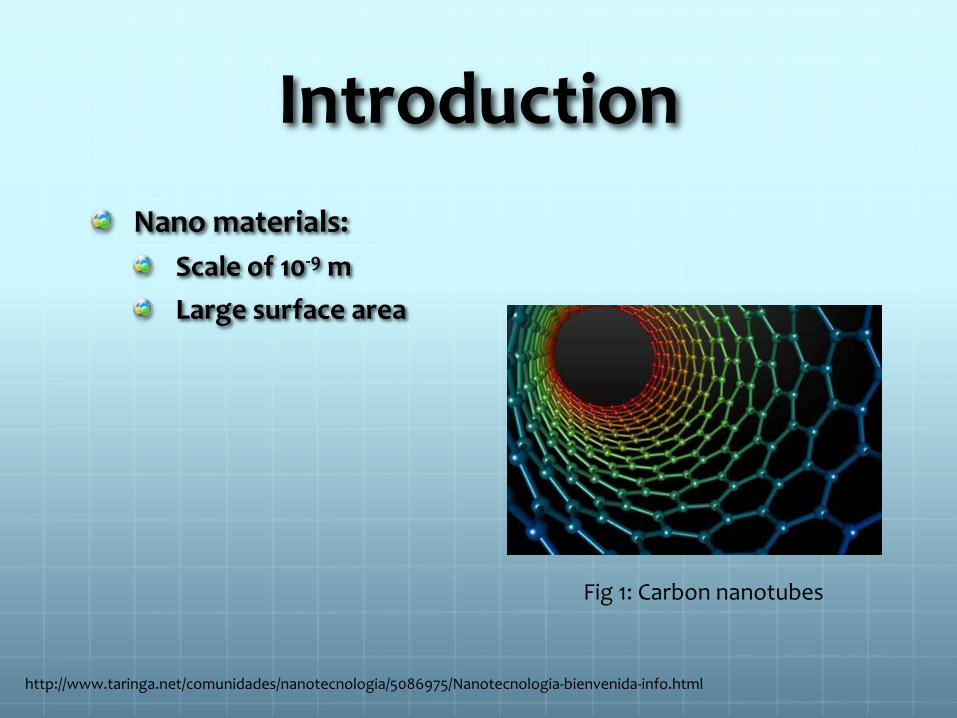
Introduction
Nano materials:
Scale of 10-9 m
Large surface area
Fig 1: Carbon nanotubes
http://www.taringa.net/comunidades/nanotecnologia/5086975/Nanotecnologia-bienvenida-info.html
Fibers
Some uses are:
Tissue scaffolds, e.g., filtration of proteins
Delivery of drugs to the humans cells
Gas sensors
Energy storage
Catalysis
Zinc Oxide
Semiconductor with large number of applications.
Has good chemical and physical properties.
Low cost

ElectrospinningTechnique
Fig 2. Fiber deposition
http://ppl.ippt.gov.pl/18-few-words-about/17-electrospinning
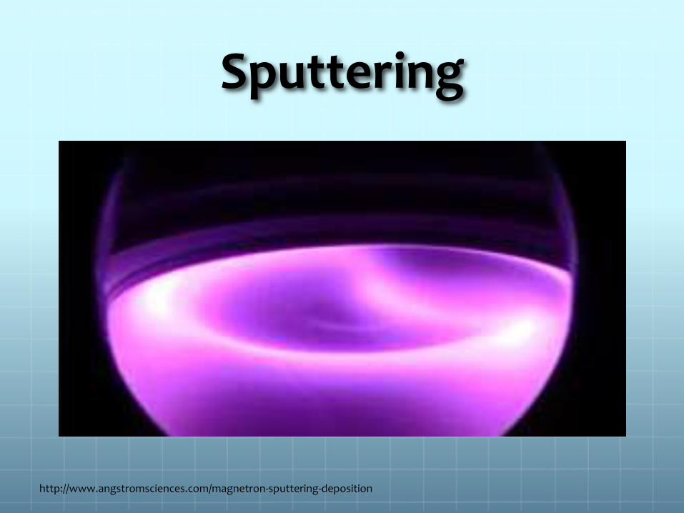
Sputtering
http://www.angstromsciences.com/magnetron-sputtering-deposition
Problem
What we want?
Detect gases such as hydrogen using ZnO.

Hypothesis
A ZnO nanometric structure with large surface area can be used as a sensitive hydrogen gas sensor.
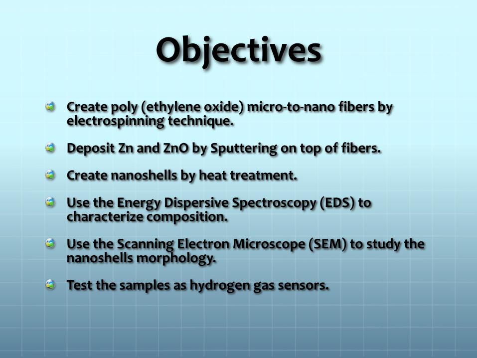
Objectives
Create poly (ethylene oxide) micro-to-nano fibers by electrospinning technique.
Deposit Zn and ZnO by Sputtering on top of fibers.
Create nanoshells by heat treatment.
Use the Energy Dispersive Spectroscopy (EDS) to characterize composition.
Use the Scanning Electron Microscope (SEM) to study the nanoshells morphology.
Test the samples as hydrogen gas sensors.
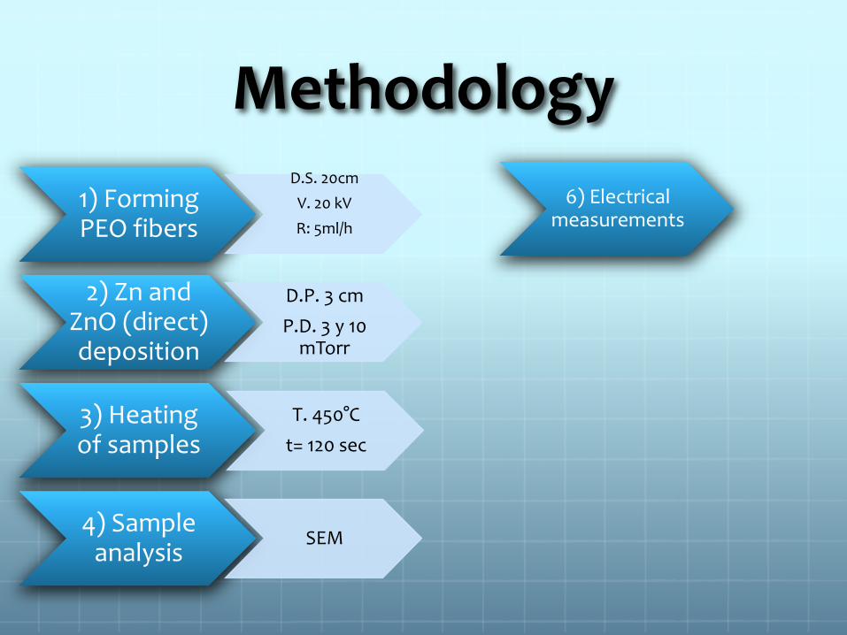
Methodology
1) Forming PEO fibers
D.S. 20cm
V. 20 kV
R: 5ml/h
2) Zn and ZnO (direct) deposition
D.P. 3 cm
P.D. 3 y 10 mTorr
3) Heating of samples
T. 450°C
t= 120 sec
4) Sample analysis
SEM
6) Electrical measurements

Results and Discussion
Fig 3. Fibers of PEO
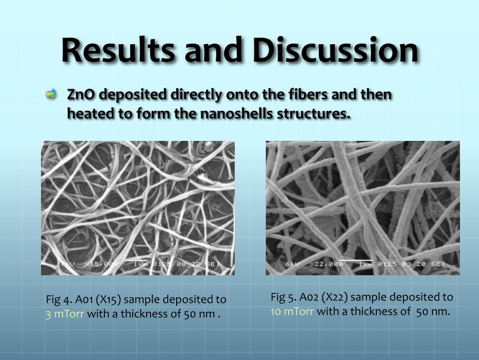
Results and Discussion ZnO deposited directly onto the fibers and then heated to form the nanoshells structures.
Fig 4. A01 (X15) sample deposited to 3 mTorr with a thickness of 50 nm .
Fig 5. A02 (X22) sample deposited to 10 mTorr with a thickness of 50 nm.

Results and Discussion
Zn deposited and then heated to form the ZnOnanoshells structures.
Fig 6. B01 (x10) deposited to 3 mtorr with a thickness of 400 nm.
Fig 7. B02 sample (x15) deposited to 10 mtorrwith a thickness of 400 nm.

Electrical Measurements
3.30E-05
3.35E-05
3.40E-05
3.45E-05
3.50E-05
3.55E-05
3.60E-05
3.65E-05
3.70E-05
3.75E-05
15.0 20.0 25.0 30.0 35.0 40.0 45.0 50.0 55.0 60.0
Cu
rre
nt
(A)
Time (min)
Current vs time for ZnO sample :Sputtering of ZnO
H2 Off
H2 On
Graph 1. Current change in ZnO samples when exposed to hydrogen.
Electrical Measurements
2.68E-03
2.88E-03
3.08E-03
3.28E-03
3.48E-03
3.68E-03
3.88E-03
0.00 20.00 40.00 60.00 80.00 100.00 120.00 140.00 160.00 180.00
Cu
rre
nt
(A)
Time (min)
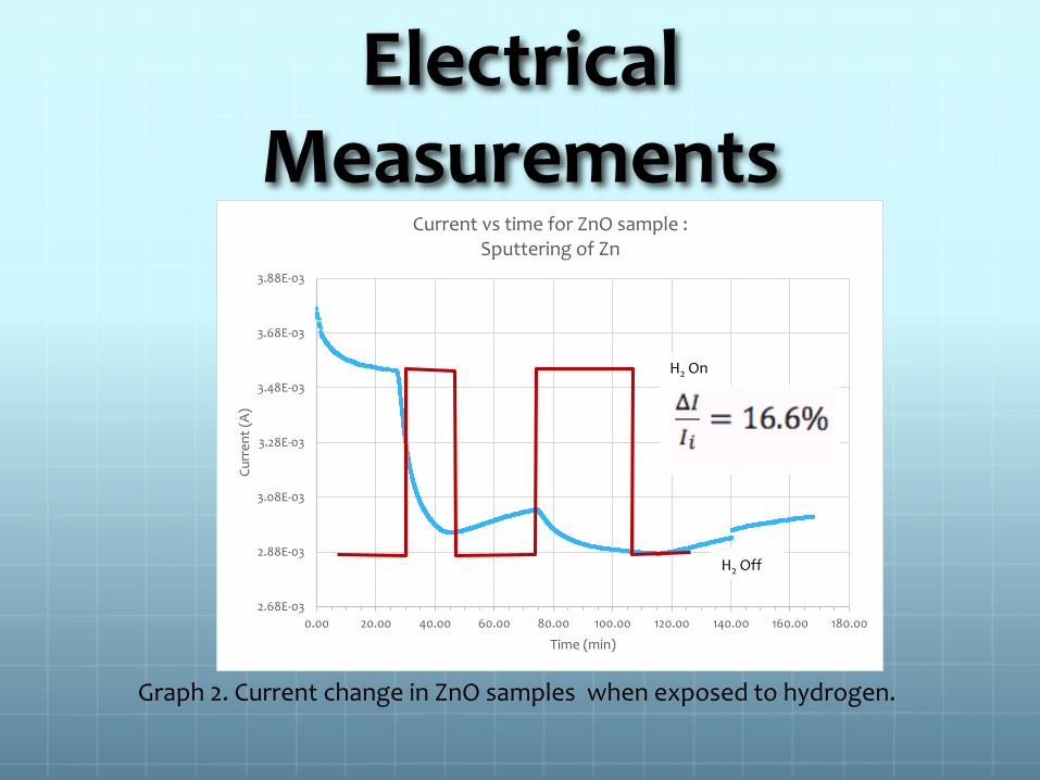
Current vs time for ZnO sample :Sputtering of Zn
H2 Off
H2 On
Graph 2. Current change in ZnO samples when exposed to hydrogen.
Electrical Measurements
2.88E-05
2.98E-05
3.08E-05
3.18E-05
3.28E-05
3.38E-05
3.48E-05
3.58E-05
3.68E-05
3.78E-05
2.88E-03
2.98E-03
3.08E-03
3.18E-03
3.28E-03
3.38E-03
3.48E-03
3.58E-03
3.68E-03
3.78E-03
0.00 10.00 20.00 30.00 40.00 50.00 60.00 70.00 80.00
Cu
rre
nt
(A)
Time (min)
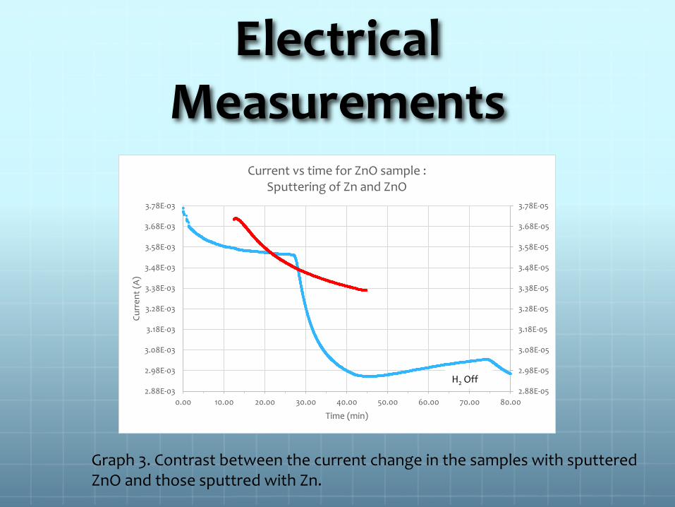
Current vs time for ZnO sample :Sputtering of Zn and ZnO
H2 Off
Graph 3. Contrast between the current change in the samples with sputtered ZnO and those sputtred with Zn.

Conclusion
The fibers and the nanoshells structures were created successfully.
Results show a greater sensitivity percent in those samples of ZnO nanoshells that were sputtered with Zn and oxidized in the heat treatment.
However, data indicted lower sensitivity percent for ZnO nanoshells that were sputtered with Zn and 50% oxygen in the reactive gas.

Acknowledgements
RISE program
CIM laboratory
References
Sui, X.; Shao, C.; Lin, Y. 2007. Photoluminescence of polyethylene oxide-ZnO composite electrospun fibers. J. Elesevier.48:1459-1463.
Park, J.; Moon, J.; Lee, S.; Lim, S.; Zyung, T. 2009. Fabrication and characterization of ZnO nanofibers by electrospinning.
J. Elsevier, 9:S210-S212.
Yamazoe, N. 2005. Toward innovations of gas sensor technology. J. Elsevier. 108:2-14.
Yang, X.; Shao, C.; Guan, H.; Li, X.; Gong, J. 2004. Preparation and characterization of ZnO nanofibers by using electrospunPVA/zinc acetate composite fiber as precursor. J. Elselvier, 7:176-178.
Synthesis and Characterization of ZnO
Nanoshells for Hydrogen Detection
Normarieli M. Passalacqua AlvaradoRISE Program
CIM LaboratoryMentor: W. Otaño Ph.D.
CIMCentro de
Investigación en
Materiales