north dakota department of transportation special provision · pdf file ·...
TRANSCRIPT


Revised 12/7/16 SP 5126(14)
NORTH DAKOTA DEPARTMENT OF TRANSPORTATION
SPECIAL PROVISION
PERMITS AND ENVIRONMENTAL CONSIDERATIONS
PROJECT NUMBER: SOIB-5-200(025)095 - PCN 19734
This Special Provision incorporates the US Army Corps of Engineers (USACE) Section 404 Permit, USFWS (US Fish and Wildlife Service) Special Use Permit, and Floodplain Permits obtained by the North Dakota Department of Transportation (NDDOT) into the bidder’s proposal. The Contractor shall be responsible for complying with all the terms and conditions as contained in the permit(s) attached hereto. Bidders shall become familiar with all standard conditions and special conditions of the permit(s) and submit their bid for the construction of this project based on the following:
Section 404 Permit The Section 404 Permit number NWO-2016-01681-BIS authorizes 3.37 acres of permanent and 3.46 acres of temporary jurisdictional wetland impacts from activities associated with widening, culvert replacement and extensions, turn lanes, grading, roadway realignment, replacing the existing bridge with a box culvert with a temporary bypass, and riprap placement. Temporary impacts were assumed by the designer and will be restored to preconstruction contours. See the Section 75 sheets of the design plans for the authorized impact footprint areas. The Section 404 Permit is attached.
USFWS Special Use Permit The USFWS Special Use Permit authorizes work on USFWS easements associated with replacing the existing bridge with a box culvert. The USFWS Special Use Permit is attached.
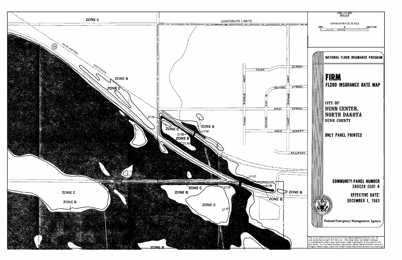
Floodplain Permit Floodplain Permits from Dunn Center and Dunn County authorize work within the 100 year floodplains within the project limits. The Floodplain Permits and Flood Insurance Rate Maps are attached.
The contractor shall be responsible for obtaining permits for impacts not authorized by the attached Permit obtained by the NDDOT.


SOIB-5-200(025)095 - PCN 19734
Dunn Center
FLOODPLAIN DEVELOPMENT PERMIT APPLICATION
NON-BUILDING SITUATION
GENERAL INFORMATION PERMIT APPLICATION # DATE: _____________ Applicant/Contact: Telephone # Address: North Dakota Department of Transportation Attn: Engineering and Environmental Services 608 East Boulevard Avenue Bismarck, ND 58505-0700 Brief project description - location of proposed development - legal description: The proposed work will include widening, replacing existing bridge with a box culvert, temporary bypass, turn lane construction, and roadway realignment. Work within the 100 year floodplain will include widening, culvert extensions, and highway realignment. Contractor: Telephone # ____________ Address: Contract Not Awarded Estimated Cost of project: $14,700,000
FLOODPLAIN DETERMINATION : (Complete the appropriate information) Project is located: 100-year floodplain? (Flood Fringe): Yes Regulatory Floodway: No Map information: FIRM Date: December 1, 1983 FIRM Zone: A6 BFE at Development Site: Development will be elevated to: DEVELOPMENT ACTIVITIES: (check all that apply and explain the activity) x Fill placement (fill brought in from outside the floodplain) Excavation (where subgrade fill is removed from the floodplain) Landscaping (cut and fill, fill borrow and placement) Construction or maintenance of a dike/levee/floodwall

STATE PROJECT NO.SECTION
NO.SHEET
NO.
12/9/2016 10:52:58 AM tbrossart
ND 2
SOIB-5-200(025)095
Revised 12/9/2016
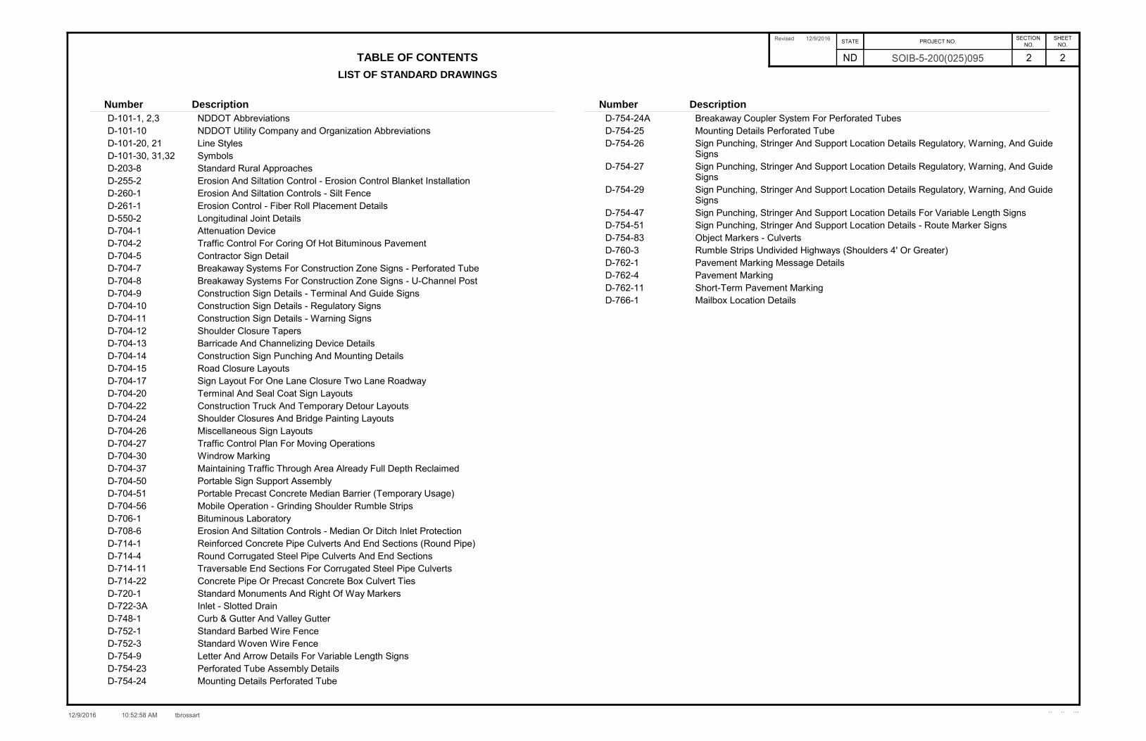
TABLE OF CONTENTS 2
LIST OF STANDARD DRAWINGS
.. .. ...
Number Description Number Description
NDDOT AbbreviationsD-101-1, 2,3NDDOT Utility Company and Organization AbbreviationsD-101-10Line StylesD-101-20, 21SymbolsD-101-30, 31,32Standard Rural ApproachesD-203-8Erosion And Siltation Control - Erosion Control Blanket InstallationD-255-2Erosion And Siltation Controls - Silt FenceD-260-1Erosion Control - Fiber Roll Placement DetailsD-261-1Longitudinal Joint DetailsD-550-2Attenuation DeviceD-704-1Traffic Control For Coring Of Hot Bituminous PavementD-704-2Contractor Sign DetailD-704-5Breakaway Systems For Construction Zone Signs - Perforated TubeD-704-7Breakaway Systems For Construction Zone Signs - U-Channel PostD-704-8Construction Sign Details - Terminal And Guide SignsD-704-9Construction Sign Details - Regulatory SignsD-704-10Construction Sign Details - Warning SignsD-704-11Shoulder Closure TapersD-704-12Barricade And Channelizing Device DetailsD-704-13Construction Sign Punching And Mounting DetailsD-704-14Road Closure LayoutsD-704-15Sign Layout For One Lane Closure Two Lane RoadwayD-704-17Terminal And Seal Coat Sign LayoutsD-704-20Construction Truck And Temporary Detour LayoutsD-704-22Shoulder Closures And Bridge Painting LayoutsD-704-24Miscellaneous Sign LayoutsD-704-26Traffic Control Plan For Moving OperationsD-704-27Windrow MarkingD-704-30Maintaining Traffic Through Area Already Full Depth ReclaimedD-704-37Portable Sign Support AssemblyD-704-50Portable Precast Concrete Median Barrier (Temporary Usage)D-704-51Mobile Operation - Grinding Shoulder Rumble StripsD-704-56Bituminous LaboratoryD-706-1Erosion And Siltation Controls - Median Or Ditch Inlet ProtectionD-708-6Reinforced Concrete Pipe Culverts And End Sections (Round Pipe)D-714-1Round Corrugated Steel Pipe Culverts And End SectionsD-714-4Traversable End Sections For Corrugated Steel Pipe CulvertsD-714-11Concrete Pipe Or Precast Concrete Box Culvert TiesD-714-22Standard Monuments And Right Of Way MarkersD-720-1Inlet - Slotted DrainD-722-3ACurb & Gutter And Valley GutterD-748-1Standard Barbed Wire FenceD-752-1Standard Woven Wire FenceD-752-3Letter And Arrow Details For Variable Length SignsD-754-9Perforated Tube Assembly DetailsD-754-23Mounting Details Perforated TubeD-754-24
Breakaway Coupler System For Perforated TubesD-754-24AMounting Details Perforated TubeD-754-25Sign Punching, Stringer And Support Location Details Regulatory, Warning, And Guide Signs
D-754-26
Sign Punching, Stringer And Support Location Details Regulatory, Warning, And Guide Signs
D-754-27
Sign Punching, Stringer And Support Location Details Regulatory, Warning, And Guide Signs
D-754-29
Sign Punching, Stringer And Support Location Details For Variable Length SignsD-754-47Sign Punching, Stringer And Support Location Details - Route Marker SignsD-754-51Object Markers - CulvertsD-754-83Rumble Strips Undivided Highways (Shoulders 4' Or Greater)D-760-3Pavement Marking Message DetailsD-762-1Pavement MarkingD-762-4Short-Term Pavement MarkingD-762-11Mailbox Location DetailsD-766-1
NOTES (revised 12/9/2016)
12/12/2016 8:50:09 AM R:\project\50200095.025\design\Addendum_A\006NT_001_notes_AD-A.docm
STATE PROJECT NO. SECTION NO.
SHEET NO.
ND SOIB-5-200(025)095 6 1
This document was originally issued and sealed by Darell Arne,
Registration Number PE-6523,
on 12/12/16 and the original document
is stored at the North Dakota Department of Transportation.
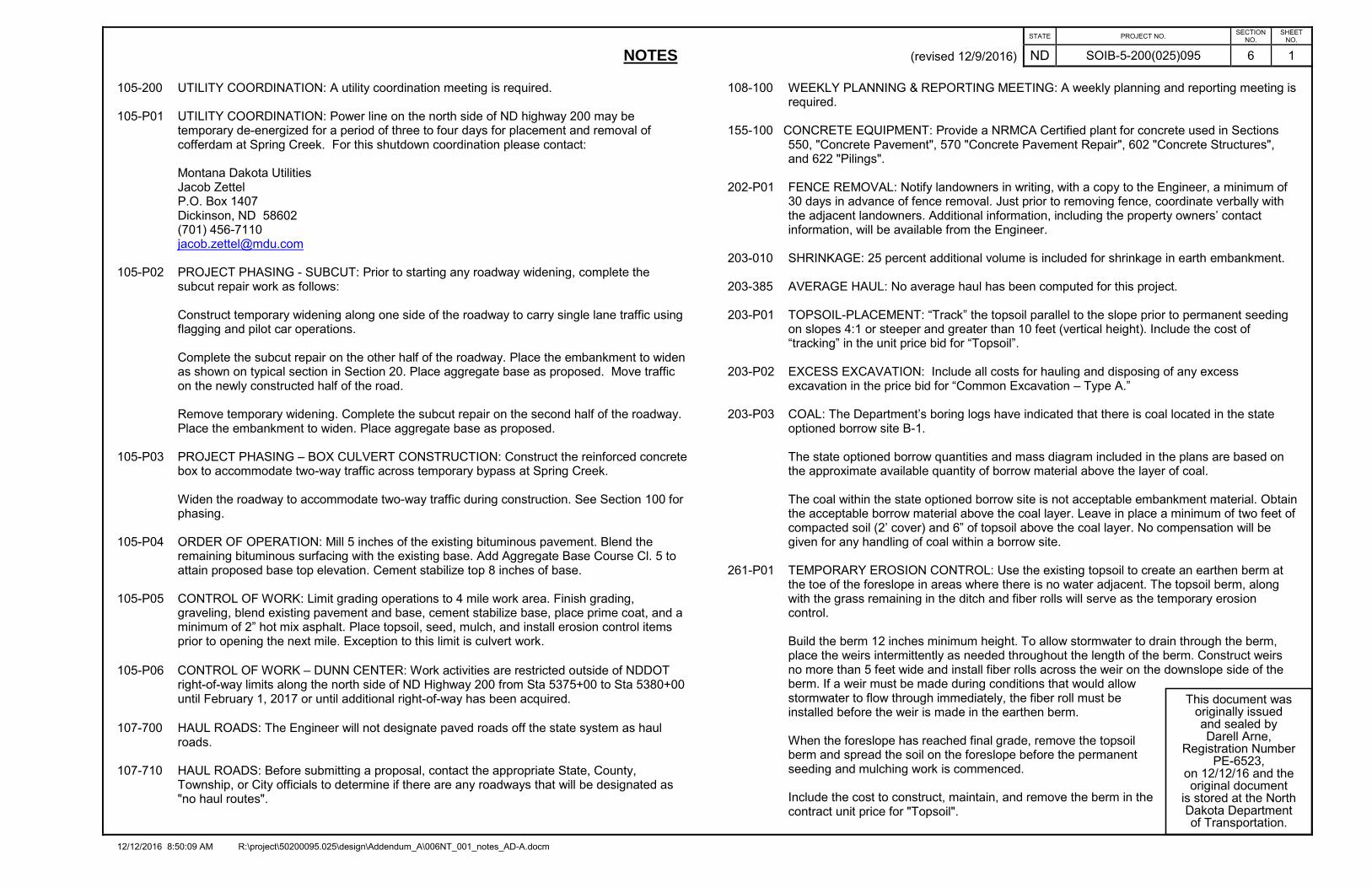
105-200 UTILITY COORDINATION: A utility coordination meeting is required. 105-P01 UTILITY COORDINATION: Power line on the north side of ND highway 200 may be
temporary de-energized for a period of three to four days for placement and removal of cofferdam at Spring Creek. For this shutdown coordination please contact:
Montana Dakota Utilities Jacob Zettel P.O. Box 1407 Dickinson, ND 58602 (701) 456-7110 [email protected]
105-P02 PROJECT PHASING - SUBCUT: Prior to starting any roadway widening, complete the
subcut repair work as follows:
Construct temporary widening along one side of the roadway to carry single lane traffic using flagging and pilot car operations. Complete the subcut repair on the other half of the roadway. Place the embankment to widen as shown on typical section in Section 20. Place aggregate base as proposed. Move traffic on the newly constructed half of the road. Remove temporary widening. Complete the subcut repair on the second half of the roadway. Place the embankment to widen. Place aggregate base as proposed.
105-P03 PROJECT PHASING – BOX CULVERT CONSTRUCTION: Construct the reinforced concrete box to accommodate two-way traffic across temporary bypass at Spring Creek.
Widen the roadway to accommodate two-way traffic during construction. See Section 100 for phasing.
105-P04 ORDER OF OPERATION: Mill 5 inches of the existing bituminous pavement. Blend the
remaining bituminous surfacing with the existing base. Add Aggregate Base Course Cl. 5 to attain proposed base top elevation. Cement stabilize top 8 inches of base.
105-P05 CONTROL OF WORK: Limit grading operations to 4 mile work area. Finish grading, graveling, blend existing pavement and base, cement stabilize base, place prime coat, and a minimum of 2” hot mix asphalt. Place topsoil, seed, mulch, and install erosion control items prior to opening the next mile. Exception to this limit is culvert work.
105-P06 CONTROL OF WORK – DUNN CENTER: Work activities are restricted outside of NDDOT right-of-way limits along the north side of ND Highway 200 from Sta 5375+00 to Sta 5380+00 until February 1, 2017 or until additional right-of-way has been acquired.
107-700 HAUL ROADS: The Engineer will not designate paved roads off the state system as haul roads.
107-710 HAUL ROADS: Before submitting a proposal, contact the appropriate State, County,
Township, or City officials to determine if there are any roadways that will be designated as "no haul routes".
108-100 WEEKLY PLANNING & REPORTING MEETING: A weekly planning and reporting meeting is required.
155-100 CONCRETE EQUIPMENT: Provide a NRMCA Certified plant for concrete used in Sections
550, "Concrete Pavement", 570 "Concrete Pavement Repair", 602 "Concrete Structures", and 622 "Pilings".
202-P01 FENCE REMOVAL: Notify landowners in writing, with a copy to the Engineer, a minimum of
30 days in advance of fence removal. Just prior to removing fence, coordinate verbally with the adjacent landowners. Additional information, including the property owners’ contact information, will be available from the Engineer.
203-010 SHRINKAGE: 25 percent additional volume is included for shrinkage in earth embankment. 203-385 AVERAGE HAUL: No average haul has been computed for this project. 203-P01 TOPSOIL-PLACEMENT: “Track” the topsoil parallel to the slope prior to permanent seeding
on slopes 4:1 or steeper and greater than 10 feet (vertical height). Include the cost of “tracking” in the unit price bid for “Topsoil”.
203-P02 EXCESS EXCAVATION: Include all costs for hauling and disposing of any excess
excavation in the price bid for “Common Excavation – Type A.” 203-P03 COAL: The Department’s boring logs have indicated that there is coal located in the state
optioned borrow site B-1.
The state optioned borrow quantities and mass diagram included in the plans are based on the approximate available quantity of borrow material above the layer of coal. The coal within the state optioned borrow site is not acceptable embankment material. Obtain the acceptable borrow material above the coal layer. Leave in place a minimum of two feet of compacted soil (2’ cover) and 6” of topsoil above the coal layer. No compensation will be given for any handling of coal within a borrow site.
261-P01 TEMPORARY EROSION CONTROL: Use the existing topsoil to create an earthen berm at
the toe of the foreslope in areas where there is no water adjacent. The topsoil berm, along with the grass remaining in the ditch and fiber rolls will serve as the temporary erosion control.
Build the berm 12 inches minimum height. To allow stormwater to drain through the berm, place the weirs intermittently as needed throughout the length of the berm. Construct weirs no more than 5 feet wide and install fiber rolls across the weir on the downslope side of the berm. If a weir must be made during conditions that would allow stormwater to flow through immediately, the fiber roll must be installed before the weir is made in the earthen berm. When the foreslope has reached final grade, remove the topsoil berm and spread the soil on the foreslope before the permanent seeding and mulching work is commenced. Include the cost to construct, maintain, and remove the berm in the contract unit price for "Topsoil".

NOTES (revised 12/9/2016)
12/12/2016 8:50:09 AM R:\project\50200095.025\design\Addendum_A\006NT_001_notes_AD-A.docm
STATE PROJECT NO. SECTION NO.
SHEET NO.
ND SOIB-5-200(025)095 6 2
This document was originally issued and sealed by Darell Arne,
Registration Number PE-6523,
on 12/12/16 and the original document
is stored at the North Dakota Department of Transportation.
302-P01 TRAFFIC SERVICE AGGREGATE: Provide 8,000 Tons of Traffic Service Aggregate to be used to maintain traffic during Phases 2, 3A, 3B, and 4. There is no need to stockpile the material. Apply a 6-inch thick mat of traffic service aggregate.
Make every effort to reuse this material throughout the life of the project. After returning traffic to normal flow, remove Traffic Service Aggregate and place topsoil. Include all costs for time, material, and labor required to supply Traffic Service Aggregate and to place, salvage, and reuse it, in the unit bid price for “Traffic Service Aggregate”. Include all costs for removal of this material in the unit bid price for “Remove Aggregate Base & Surfacing”.
430-P01 PAVING SEAMS: Paving seams are not allowed in the wheel path of the driving lane. 704-100 TRAFFIC CONTROL SUPERVISOR: Provide a Traffic Control Supervisor. 704-200 PRECAST CONCRETE MEDIAN BARRIERS – STATE FURNISHED: Obtain 16 barriers
from Belfield Maintenance Yard. Return barriers to Belfield Maintenance Yard, located at 898 8th St. NW, Belfield, ND 58622-7418.
Some 4 inch x 4 inch boards are available at the return location. Provide any additional 4 inch x 4 inch boards necessary to stack barriers. The boards will become property of the Department. Include the cost for boards in the contract unit price for "Precast Concrete Median Barrier - State Furnished".
704-255 TRAFFIC CONTROL FOR SHOULDER DROP-OFF: If the shoulder and adjacent driving
lane are not even at the end of the day, the following criteria will apply: Place the following sign assembly at the locations listed below. Sign Assembly: Sign No. W8-9a-48 "Shoulder Drop Off" and supplemental plate Sign No. W20-52-54 to identify the distance. Locations:
In advance of the drop off;
Spaced at each mile from the advance sign; and
At major intersections (CMC routes, state and US highways, and Interstate Ramps).
If the difference in elevation between the shoulder and the driving lane is 2" or greater, construct a slough on the driving lane that is 4:1 or flatter. If the difference in elevation between the shoulder and driving lane is less than 2", no slough is required. Sign assemblies will be measured and paid for according to Section 704 "Temporary Traffic Control".
704-P01 TRAFFIC CONTROL DEVICES: The traffic control devices list has been developed using the layouts shown in the plans and the following layouts shown on the Standard Drawings.
D-704-15 Layout Type A to be used any time conditions exist. (Quantities are based on two one lane closures happening simultaneously.) D-704-15 Layout Type B Temporary Bypass locations. Devices have been supplied for the box culvert temporary bypass. D-704-17 Layout for One Lane Closure Two Lane Roadway D-704-20 Layout Type G as the basis of the Construction Signing Sheet. D-704-22 and D-704-26, Layouts Type K, Type L, and Type Y for Construction Truck Hauling Material. D-704-26 Layouts Type BB, CC, EE, FF, and GG as needed.
D-704-30 Layout Windrow Marking. D-704-37 Construction Sign Layout
Make the embankment through the area in which traffic will be maintained on at all times traversable with 4:1 slopes or flatter the same day it is placed/removed, or the Contractor needs to provide 24 hour flagging at the Contractor’s expense. When installing layout G from Standard D-704-20, move sign W3-5-48 and the sign assembly containing signs R2-1-48 and R2-1a-24 with the work area as it progresses through the construction zone. Place the R2-1-48 assembly a minimum of 500 feet in advance of flagging signs. Traffic control quantities for uneven pavement have been developed based on a 6 mile limitation for the paving operations. The required traffic control signs and devices are included in the "Traffic Control Devices List" and will be measured and paid at the contract unit price for each device.
704-P02 PORTABLE CHANGEABLE MESSAGE SIGN: Stage Portable Changeable Message Signs
(PCMS) prior to removing any pavement on the project. Use PCMS to display information throughout the project duration. The Engineer will determine the location and message to be displayed. Within 20 minutes of the Engineer’s request, the message will be displayed on both signs by a person trained in the operation of the portable changeable message sign. The signs will be equipped with remote access and include a booster if a cell phone signal is not available where the signs are located. The PCMS will conform to the requirements of the MUTCD, Part 6, and specifications. Upon completion of the project, the Contractor retains ownership of the PCMS.

NOTES (revised 12/9/2016)
12/12/2016 8:50:09 AM R:\project\50200095.025\design\Addendum_A\006NT_001_notes_AD-A.docm
STATE PROJECT NO. SECTION NO.
SHEET NO.
ND SOIB-5-200(025)095 6 3
This document was originally issued and sealed by Darell Arne,
Registration Number PE-6523,
on 12/12/16 and the original document
is stored at the North Dakota Department of Transportation.
704-P03 TRAFFIC CONTROL FOR BITUMINOUS PAVEMENT: Provide traffic control consisting of a temporary road closure, flagging, and a pilot car. Traffic control device quantities are based on a 6 mile limitation and the list below. Provide additional devices at no additional cost to the Department.
1. Standard D-704-15, layout A; 2. Standard D-704-20, layout G 3. Standard D-704-22, layouts K and L; and 4. Standard D-704-26, layouts CC, EE, and GG.
When installing layout G from Standard D-704-20, move sign W3-5-48 and the sign assembly containing signs R2-1-48 and R2-1a-24 with the work area as it progresses through the construction zone. Place the R2-1-48 assembly a minimum of 500 feet in advance of flagging signs.
704-P04 TRAFFIC CONTROL FOR SUBCUT: 36 hours of flagging has been provided in the plans to complete the subcut. Any additional flagging will be at the Contractor’s expense.
706-P01 FIELD OFFICE: Provide a field office which meets the following requirements:
1. Minimum total area of 440 square feet 2. Indoor bathroom facilities and supplies with weekly cleaning services 3. Hookups for heat, electricity, sewer, and potable water. 4. Minimum cabinet space of 32 cubic feet 5. Minimum counter space of 40 square feet 6. Air conditioner with a minimum of 20,000 BTUs 7. Lighting with a minimum of 110 foot-candles 8. DSL broadband internet and a router that broadcasts Wi-Fi and will allow for hard wiring
of a computer. 9. Photocopy/Printer with scanning capabilities capable of 11x17 photocopies and toner to
last the duration of the project. Other features to include digital copying and scanning. Copier/printer machine with operating software compatible with that used by the NDDOT. Supply a photocopier with enough toner to last the length of the project and with the following capabilities:
a. Printing; b. Scanning; and c. Producing 11 x 17 photocopies and prints.
Place the field office on the project, or as close to the project as possible. The Contractor is responsible for the pay for the following: - Rental fees; - Heating; - Electrical; - Sewer, and - Potable water.
Make the field office available for occupancy one week before the start of the project. The Engineer will approve the location and the condition of the office. Do not remove the field office until the Engineer releases the field office.
The Engineer is responsible for the following items: Furnishing office equipment; Supplying paper; and Supplying and paying for internet service. All requirements of the Field Office are subject to approval by the Engineer. Include the costs for the field office in the bid item "Field Office".
Schedule for Payments:
- 25% when set up on site. - 50% when 30% of the work is complete. - 75% when 60% of the work is complete. - 100% when project is complete.
714-P01 PIPE EXTENSIONS: If the Contractor encounters silted-in pipes at locations where pipe are
to be extended, the silted-in material will be removed from the pipes before extending them. Remove silt 50 feet beyond the end of the pipe. The cost of removing the silt is included in the price bid for “Common Excavation-Type A”. Assume all extended pipes require silt cleanout.
714-P02 PIPE EXTENSIONS: If water is encountered at locations where pipes are to be extended,
provide dewatering if necessary according to site conditions. Include all costs associated with dewatering in the price bid for pipe installation.
752-P01 FENCE BARBED WIRE 3 STRAND: Install the top and bottom wires in accordance with
Standard Drawing D-752-1. Evenly space the third wire in between the top and bottom wires. When tying into existing fence, match the post type to be used with the existing fence posts.
752-P02 FENCE WOVEN WIRE: Install the woven wire fence to match the height of the existing
woven wire fence in place. Install 2 strands of barbed wire above the woven wire fence to match the existing barbed wire strands in place. Include the cost to install 2 strands of barbed wire in the price bid for “Fence Woven Wire”.
752-P03 FENCE TEMPORARY INSTALL & REMOVE: Install 3-strand barbed wire fence prior to
removing the existing fence. Include the cost to furnish, install, and remove all temporary fencing, temporary corner assemblies, and miscellaneous hardware for temporary fencing in the price bid for “Fence Temporary Install & Remove”.
762-050 PAVEMENT MARKING: If the Engineer and Contractor agree, plan quantity will be used as
the measurement for payment for pavement marking items.
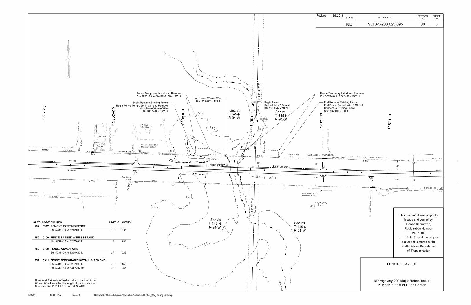
Sta 5235+99 to Sta 5237+00 - 150' Lt
Fence Temporary Install and Remove
Sta 5238+22 - 100' Lt
End Fence Woven Wire
Sta 5239+42 - 100' Lt
Barbed Wire 3 Strand
Begin Fence
Sta 5239+64 to 5242+00 - 150' Lt
Fence Temporay Install and Remove
Sta 5235+99 - 100' Lt
Install Fence Woven Wire
Begin Fence Temporary Install and Remove
Begin Remove Existing Fence
Sta 5242+00 - 100' Lt
Connect to Existing Fence
End Fence Barbed Wire 3 Strand
End Remove Existing Fence
SPEC CODE BID ITEM UNIT QUANTITY
202 0312 REMOVE EXISTING FENCE
Sta 5235+99 to 5242+00 Lt LF 601
752 0100 FENCE BARBED WIRE 3 STRAND
Sta 5239+42 to 5242+00 Lt LF 258
752 0700 FENCE WOVEN WIRE
Sta 5235+99 to 5238+22 Lt LF 223
752 0911 FENCE TEMPORARY INSTALL & REMOVE
Sta 5235+99 to 5237+00 Lt LF 150
Sta 5239+64 to Sta 5242+00 LF 285
See Note 752-P02: FENCE WOVEN WIRE.
Woven Wire Fence for the length of the installation.
Note: Add 2 strands of barbed wire to the top of the
HG6136RWMW
20ALUMCAPHE189
RWMIPHG6135
HG6157RWMIP
R-94-W
T-145-N
Sec 29
R-94-W
T-145-N
Sec 28
R-94-W
T-145-N
Sec 21
R-94-W
T-145-N
Sec 20
AL6108MILE 99
R Mkr 99 PLAN 210+98.31003
25'
Sec line
Sec line
Sec line
Sec line
S 88̂ 28' 00" E
S 0
1̂ 2
2' 3"
W
N 0
1̂ 3
3' 5"
E
5225
+00
5230
+00
5235
+00
5240
+00
5245
+00
5250
+00
N 88̂ 24' 32" W
80
SOIB-5-200(025)095 5
FENCING LAYOUT
Killdeer to East of Dunn Center
ND Highway 200 Major Rehabilitation
4888
12-9-16
Revised 12/9/2016STATE PROJECT NO.
ND
NO.
SHEET
NO.
SECTION
12/9/2016 tbrossart R:\project\50200095.025\eplans\addendum\Addendum1\080LO_005_Fencing Layout.dgn10:48:14 AM
of Transportation
North Dakota Department
document is stored at the
on and the original
PE- ,
Registration Number
issued and sealed by
This document was originally
Ranka Samardzic,
B Wire
B Wire
Trash pit
FO MkrFO Mkr
Post
Lg Trees
Lg Trees
B Wire
Lg Trees
B Wire
Gate
E Mtr
Elec Box &
FO Box
Dirt
B Wire
Elevation: 2222.4
OH Clearance: 25.1
Dirt
Elec Box & Mkr Scattere
d R
ks
Support Pole
FO Mkr
Elec Box & Mkr
FO Ped & MkrGate
Scattered Rks
B Wire
Bushes
B Wire
Gate
B Wire
B Wire
Dirt
Lg Rk
FO Mkr
Dirt
B Wire
BushesLg trees
Lg trees
Lg tre
es
Lg trees
FO Mkr
Sprin
g Creek
Spring Cre
ek
Scattered Rks
Gate
Dirt
Scattered Rks
Abn farm Bldg
B Wire
Lg Rk
Slide Area
Elevation: 2233.1
OH Clearance: 31.1
125'
75'
125'
125'
33' 33'
33' 33'
125'
75'

Horizontal braceHorizontal braceHorizontal braceHorizontal brace
5" Brace post
Ground line
Chain & lock
steel post
4’ section of
wire loops (Staple to post)
Double strand 9 ga.
9’ 6"9’ 6"16’ 6"9’ 6"9’ 6"1’
4’
4’
Horizontal brace
USE OF POST
End post
Line post
Corner post
Brace post
Gate post
dia.
Post
length
Post
length
Post
Lbs/Ft
Post wt.
Lbs
Anchor wt.
Treated wood Steel
As approved by the Engineer
8"
5"
5"
5"
Var.
8’
8’
8’
8’
1.33 0.67
4.107’ (Conc.)
(Conc.)7’ 3.19
WRAP-AROUND DETAIL
Side view Top view
line post
Wood
Wire
Staple
Post
SPLICE DETAIL
as shown.
as shown or wire clamps may be used
woven wire fence splice may be tied
At the option of the Contractor the
Wire clamp
each wire.
least five turns about
Each end shall have at
shall be tied as shown.
All horizontal wires
Horizontal brace
Horizontal brace
Two loops
Ground line
Horizontal b
race
Horizontal b
race
Horizontal b
race
Two loop
s
Line post
Line post
brace
Horizontal
in brace
Shallow V cut
Horizontal brace Horizontal brace Horizontal brace Horizontal brace
Horizont
al brace
Ground line
Inslope
DOUBLE BRACE ASSEMBLY
5" Brace post
Ground line
POST SIZES
9’ 6" 9’ 6"
4’
4’
5"
39"
4"
5"
39"
4"
4’
4’
9’ 6"9’ 6"
Normal termination
and interchange crossroads.Termination at grade separations
9’ 6"
9’ 6"
9’ 6"
9’ 6"
9’ 6"
3 Brace spa
n when f
ence lin
e is ove
r 330’
2 Brace span when fence line is less than 330’
4’
4’
39"
4"
4’
4’
5"
9’ 6" 9’ 6"
18"
18"
18"
5"
39"
4"
4’
4’
4’
"213
"213
"213
" Brace post412"x2"x
" Brace pos
t
213
" Corner post41"x 2
1"x 2212
NOTES
6’-6" 6’-6"
VEHICLE GATE
7"
6"
"215
5"
"214
4""2
133"
39"
4"
5"
16’ 6"
6"
12"
18"
48"
30"
(16’-6" Spacing)
STEEL LINE POST
(16’-6" Spacing)
WOOD LINE POST
36"
6" Staple
FASTENING TO POSTS
9 Ga. Wire
Line post
9’ 6"
18"
18"
18"
36"
6"
STEEL POSTS
FENCE TERMINAL
8" Corner post
5" Brace post
" Brace post
213
" Brace pos
t
213
5" Brace pos
t
LINE POST DETAIL
"| x 6"41
Steel pinand tie 5 turns about wire
Wrap around post twice
Anchor Plate
STEEL POSTS
CORNER AND DOUBLE BRACE ASSEMBLY
HORIZONTAL BRACE DETAIL
Wood post Top view
once around each post.
tight before twisting. Wrap
9 ga. wire should be singing
tight be
fore twis
ting.
9 ga. wir
e should be
singing
once around each post.
tight before twisting. Wrap
9 ga. wire should be singing5" End post
8" Corner post
(a) 9’ 6"
field.
necessary by the Engineer in the
shall be installed when determined
Additional 9’6" spans on inslopes(a)once around each post.
tight before twisting. Wrap
9 ga. wire should be singing
once around each post.
tight before twisting. Wrap
9 ga. wire should be singing
5" Brace post
5" Gate post
5" Gate post5" Brace post
5" Brace post5" Brace post 5" Brace post 5" Brace post
12" round or square concrete
concrete
Cast in place
CORNER ASSEMBLY
line post
"T" steel
corner post
Angle steel
be tied or wrapped.
not be welded, but shall
Line and stay wires shall
in the plans.
be determined by the contractor unless otherwise specified
5. The type of posts to be used, either wood or steel, shall
a double brace shall be installed.
grade is so sharp that woven wire will not conform to the grade,
4. If in the opinion of the Engineer in the field the change in
Bottom wire shall be stapled.
Intermediate wires shall be stapled not more than 10" apart.
3. Top wire of the woven wire fence shall be stapled separately.
assemblies shall not exceed 1320 feet.
adjacent fence terminals, corner assemblies or double brace
on the plans or established by the Engineer. The distance between
2. Double Brace Assembly shall be installed at locations shown
or fence terminals.
be made for gates, corner assemblies, double brace assemblies
1. No deduction in measured pay length of woven wire fence will
FENCE TERMINAL
5" Brace post
10/2/2012
2930
STANDARD WOVEN WIRE FENCE D-752-3
REVISIONS
DATE CHANGE
DEPARTMENT OF TRANSPORTATION
NORTH DAKOTA
of Transportation
North Dakota Department
document is stored at the
on and the original
PE- ,
Registration Number
issued and sealed by
This document was originally10-02-12
Roger Weigel,