note 8 electric actuators - college of engineering · note 8 electric actuators . lecture notes of...
TRANSCRIPT
Lecture Notes of ME 475: Introduction to Mechatronics
Department of Mechanical Engineering, University Of Saskatchewan, 57 Campus Drive, Saskatoon, SK S7N 5A9, Canada
1
Note 8
Electric Actuators

Lecture Notes of ME 475: Introduction to Mechatronics
Department of Mechanical Engineering, University Of Saskatchewan, 57 Campus Drive, Saskatoon, SK S7N 5A9, Canada
2
1. Introduction In a typical closed-loop, or feedback, control of a machine or a process, the controller compares the actual sensor measurement with the desired value and then adjusts the signal to the actuator accordingly. The actuator, or prime mover, converts signals into a physical quantity to initiate a motion, thereby regulating the controlled variable. In general, actuators are classified into three categories: electric, pneumatic, and hydraulic. The following table provides a qualitative comparison among these types of actuators.
Table 1 Comparison of Pneumatic, Hydraulic, and Electric Actuators
Electric actuators convert electric power into mechanical power. Electric actuators are available in one of two types, direct current (DC) and alternating current (AC). AC induction and synchronous motors are ideal for constant speed applications with little load variations. AC motors use line current to directly provide more power compared to DC motors of similar size. For position and speed control applications involving variable loads, DC motors are favored. DC motors fall in one of three categories: conventional or brushed DC motors, brushless DC motors, and step motors. Servos are basically DC motors fitted with sensing and control components.
Lecture Notes of ME 475: Introduction to Mechatronics
Department of Mechanical Engineering, University Of Saskatchewan, 57 Campus Drive, Saskatoon, SK S7N 5A9, Canada
3
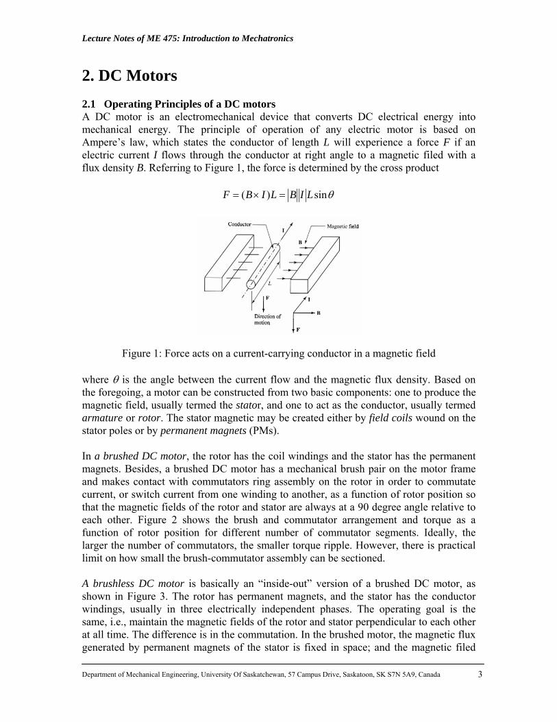
2. DC Motors 2.1 Operating Principles of a DC motors A DC motor is an electromechanical device that converts DC electrical energy into mechanical energy. The principle of operation of any electric motor is based on Ampere’s law, which states the conductor of length L will experience a force F if an electric current I flows through the conductor at right angle to a magnetic filed with a flux density B. Referring to Figure 1, the force is determined by the cross product
θsin)( LIBLIBF =×=
Figure 1: Force acts on a current-carrying conductor in a magnetic field where θ is the angle between the current flow and the magnetic flux density. Based on the foregoing, a motor can be constructed from two basic components: one to produce the magnetic field, usually termed the stator, and one to act as the conductor, usually termed armature or rotor. The stator magnetic may be created either by field coils wound on the stator poles or by permanent magnets (PMs). In a brushed DC motor, the rotor has the coil windings and the stator has the permanent magnets. Besides, a brushed DC motor has a mechanical brush pair on the motor frame and makes contact with commutators ring assembly on the rotor in order to commutate current, or switch current from one winding to another, as a function of rotor position so that the magnetic fields of the rotor and stator are always at a 90 degree angle relative to each other. Figure 2 shows the brush and commutator arrangement and torque as a function of rotor position for different number of commutator segments. Ideally, the larger the number of commutators, the smaller torque ripple. However, there is practical limit on how small the brush-commutator assembly can be sectioned. A brushless DC motor is basically an “inside-out” version of a brushed DC motor, as shown in Figure 3. The rotor has permanent magnets, and the stator has the conductor windings, usually in three electrically independent phases. The operating goal is the same, i.e., maintain the magnetic fields of the rotor and stator perpendicular to each other at all time. The difference is in the commutation. In the brushed motor, the magnetic flux generated by permanent magnets of the stator is fixed in space; and the magnetic filed

Lecture Notes of ME 475: Introduction to Mechatronics
Department of Mechanical Engineering, University Of Saskatchewan, 57 Campus Drive, Saskatoon, SK S7N 5A9, Canada
4
generated by the armature is also maintained fixed in space by the mechanical brush-commutator assembly and perpendicular to that of the stator. In the case of brushless DC motor, the field magnetics is established by the rotor and it rotates in space with the rotor. Therefore, the stator winding current has to be controlled as a function of rotor position so as to keep the stator generated magnetic field always perpendicular to the magnetic field of the rotor.
Figure 2: Commutation and torques variation as a function of angular position of the rotor.
Figure 3: DC motor types: brushed DC and brushless DC.

Lecture Notes of ME 475: Introduction to Mechatronics
Department of Mechanical Engineering, University Of Saskatchewan, 57 Campus Drive, Saskatoon, SK S7N 5A9, Canada
5
2.2 Drives of DC Brushed Motors Drive is considered as the power amplification stage of an electric motor. The most common type of power stage amplifier used for DC brushed motors is an H-bridge amplifier (Figure 4). The H-bridge usues four power transistors. When controlled in pairs (Q1 and Q4, or Q2 and Q3), it changes the direction of the current, hence the direction of generated torque. Notice that the pair of Q1 and Q3, or Q2 and Q4 should never be turned ON at the same time because it would form a short-circuit path between supply and ground. The diode across each transistor serves the purpose of suppressing voltage spikes and provides a freewheeling path for the current to follow. Large voltage spikes occur across the transistor in the reverse direction due to the inductance of the coils. The diodes provide the alterative current path for inductive loads and lets current pass through the coil.
Figure 4: Block diagram of the brushed DC motor drive: PWM amplifier with current feedback control By controlling the current magnitude through the power transistors, the magnitude of the torque is controlled. For this purpose, the pulse width modulation (PWM) signal is usually used. The PWM circuit converts an analog input signal to a fixed frequency but variable pulse width signal. By modulating the ON-OFF time of the pulse width, a desired average voltage can be controlled. 2.3 DC Motor: Electromechanical Dynamic Model Motor-driven systems with Gears. Motor-driven systems are rarely seen without associated gear trains driving the load. Figure 5 shows gears driving a rotational inertial, spring, and viscous damper, in which N1 and N2 are the numbers of teeth of the input gear and output gear, respectively.
Lecture Notes of ME 475: Introduction to Mechatronics
Department of Mechanical Engineering, University Of Saskatchewan, 57 Campus Drive, Saskatoon, SK S7N 5A9, Canada
6
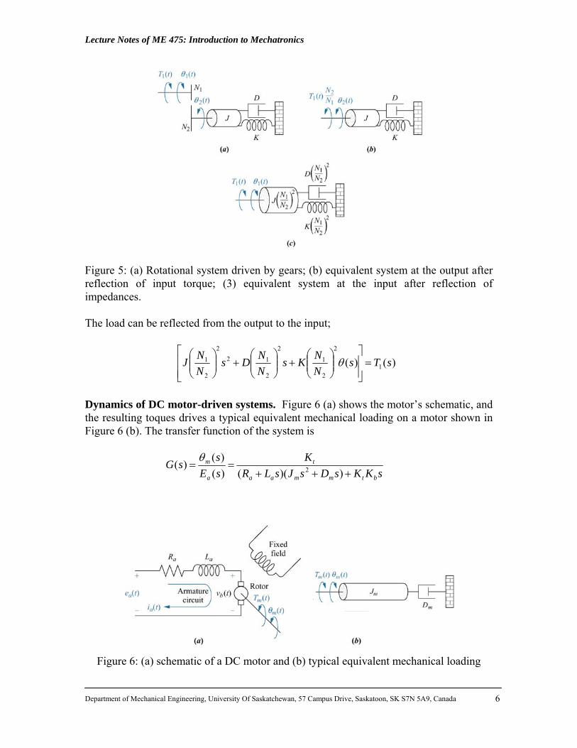
Figure 5: (a) Rotational system driven by gears; (b) equivalent system at the output after reflection of input torque; (3) equivalent system at the input after reflection of impedances. The load can be reflected from the output to the input;
)()( 1
2
2
1
2
2
122
2
1 sTsNNKs
NNDs
NNJ =
⎥⎥⎦
⎤
⎢⎢⎣
⎡⎟⎟⎠
⎞⎜⎜⎝
⎛+⎟⎟
⎠
⎞⎜⎜⎝
⎛+⎟⎟
⎠
⎞⎜⎜⎝
⎛θ
Dynamics of DC motor-driven systems. Figure 6 (a) shows the motor’s schematic, and the resulting toques drives a typical equivalent mechanical loading on a motor shown in Figure 6 (b). The transfer function of the system is
sKKsDsJsLR
KsEssG
btmmaa
t
a
m
+++==
))(()()()( 2
θ
Figure 6: (a) schematic of a DC motor and (b) typical equivalent mechanical loading
Lecture Notes of ME 475: Introduction to Mechatronics
Department of Mechanical Engineering, University Of Saskatchewan, 57 Campus Drive, Saskatoon, SK S7N 5A9, Canada
7
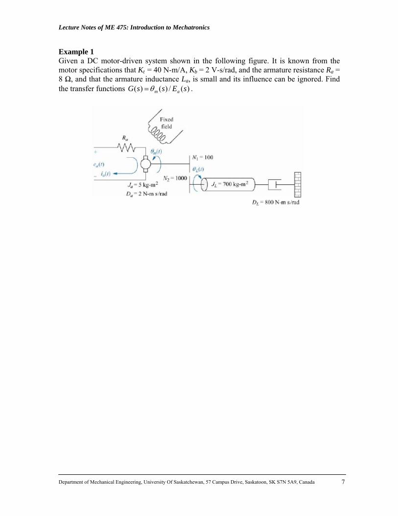
Example 1 Given a DC motor-driven system shown in the following figure. It is known from the motor specifications that Kt = 40 N-m/A, Kb = 2 V-s/rad, and the armature resistance Ra = 8 Ω, and that the armature inductance La, is small and its influence can be ignored. Find the transfer functions )(/)()( sEssG amθ= .
Lecture Notes of ME 475: Introduction to Mechatronics
Department of Mechanical Engineering, University Of Saskatchewan, 57 Campus Drive, Saskatoon, SK S7N 5A9, Canada
8
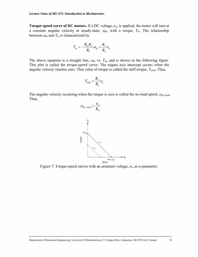
Torque-speed curve of DC motors. If a DC voltage, ea, is applied, the motor will turn at a constant angular velocity at steady-state, ωm, with a torque, Tm. The relationship between ωm and Tm is characterized by
aa
tm
a
tbm e
RK
RKKT +−= ω
The above equation is a straight line, ωm vs. Tm, and is shown in the following figure. This plot is called the torque-speed curve. The toques axis intercept occurs when the angular velocity reaches zero. That value of torque is called the stall torque, Tstall. Thus,
aa
t eRKT =stall
The angular velocity occurring when the torque is zero is called the no-load speed, ωno-load. Thus,
b
a
Ke
=−loadnoω
Figure 7: Torque-speed curves with an armature voltage, ea, as a parameter.

Lecture Notes of ME 475: Introduction to Mechatronics
Department of Mechanical Engineering, University Of Saskatchewan, 57 Campus Drive, Saskatoon, SK S7N 5A9, Canada
9
Example 2 Find the transfer function )(/)()( sEssG aLθ= , for the motor and load shown in the following figure. The torque-speed curve is given by 2008 +−= mmT ω if the input voltage is 100 V.
3. Step Motors Step motor, also called stepper motor, electromechanical construction is such that it moves in discrete mechanical steps. A change in phase current from one state to another creates a single step change in the rotor position. If the phase current state is not changed, the rotor position stays in that stable position. The operating principle of a basic stepper motor is shown schematically in Figure 8, in which the rotor has one north and one south pole permanent magnet; and the stator has four-pole, two-phase winding with four switches. At any given time either switch 1 or 2, and 3 or 4 can be ON to affect the polarity of electromagnets. For each state, there is a corresponding stable rotor position. Consider the switching sequence shown on the left four illustrations at the bottom of Figure 8. At any given time, all of the stator phases are energized; and each rotor pole is

Lecture Notes of ME 475: Introduction to Mechatronics
Department of Mechanical Engineering, University Of Saskatchewan, 57 Campus Drive, Saskatoon, SK S7N 5A9, Canada
10
attracted by two winding poles. Following the four switching sequence, the rotor would take the shown stable positions. The type of phase current switch, where both phases are energized, is referred to as “full-step” model of operation. Consider the four sequences of switch stats shown in the right-side of Figure 8. In this case, only one of the stator phases is energized while the other phased is OFF. The corresponding stable rotor positions are shown in the figure. However, notice that since the magnetic force pulling the rotor is provided by only one phase, the torque of the motor at these switch states is less than (approximately ½) that at the full –step mode. This mode of switching phase current is referred to as the “half-step” mode.
Figure 8: Operating principles of a stepper motor.

Lecture Notes of ME 475: Introduction to Mechatronics
Department of Mechanical Engineering, University Of Saskatchewan, 57 Campus Drive, Saskatoon, SK S7N 5A9, Canada
11
In realty, a stepper motor is usually constructed to have multiple "toothed" electromagnets arranged around a central gear-shaped rotor, as shown in Figure 9. The electromagnets are energized by an external control circuit, such as a microcontroller. To make the motor shaft turn, first one electromagnet is given power, which makes the gear's teeth magnetically attracted to the electromagnet's teeth. When the gear's teeth are thus aligned to the first electromagnet, they are slightly offset from the next electromagnet. When the next electromagnet is turned on and the first is turned off, the gear rotates slightly to align with the next one, and from there the process is repeated. Each of those slight rotations is called a "step." In that way, the motor can be turned a precise angle.
Figure 9: Stepper motor rotating a small angel in each step.

Lecture Notes of ME 475: Introduction to Mechatronics
Department of Mechanical Engineering, University Of Saskatchewan, 57 Campus Drive, Saskatoon, SK S7N 5A9, Canada
12
Figure 10 shows the stator windings connections of two drive configurations: unipolar drive, and bipolar drive. The difference between these configurations is that at a switched on state, only half of the winding is used in the unipolar drive, and the whole winding is used in the bipolar drive.
Figure 10: Stator windings connections of two drive configurations: (a) unipolar drive, and (b) bipolar drive. 4. AC Induction Motors An AC motor is an electric motor that is driven by an alternating current. An AC motor consists of two basic parts: (1) an outside stationary stator having coils supplied with AC current to produce a
rotating magnetic field, and (2) an inside rotor attached to the output shaft that is given a torque by the rotating field. The number of phases of the motor is determined by the number of independent windings connected to a separate AC line phase. Number of motor poles refers to the number of electromagnetic poles generated by the winding. Typical number of poles are P=2, 4, or 6, as shown in Figure 10. The coil wire for each phase can be distributed over the periphery of the stator to shape the magnetic flux distribution.

Lecture Notes of ME 475: Introduction to Mechatronics
Department of Mechanical Engineering, University Of Saskatchewan, 57 Campus Drive, Saskatoon, SK S7N 5A9, Canada
13
Figure 10: Stator windings of AC induction motors: (a) two poles, (b) 4 poles, and (c) 6 poles. In an AC induction motor, the current in the stator generates a magnetic field which induces a current in the rotor conductors. This induction is a result of relative motion between stator magnetic field (rotating electrically due to AC current) and the rotor conductors (which is initially stationary). Stator AC current sets up a rotating flux field. The changing magnetic field induced emf voltage, hence current, in the rotor conductors. The induced current in the rotor in turn generates its own magnetic field. The interaction of the two magnetic fields (the magnetic field of the rotor trying to keep up with the magnetic field of the stator) generates the torques on the rotor. When the rotor speed is identical to the electrical rotation speed of stator field, there is no induced voltage on the rotor, and hence the generated torques is zero. This is the main operating principle of an AC induction motor.