notebook computer user's guide - gericom support &...
TRANSCRIPT

User's Guide
Notebook Computer

Preface
Copyright 2003
All Rights Reserved.
Manual edition, 2003
The information in this document is subject to change without prior notice in order to improve reliability, design and function and does not represent a commitment on the part of the manufacturer.
In no event will the manufacturer be liable for direct, indirect, special, incidental, or consequential damages arising out of the use or inability to use the product or documentation, even if advised of the possibility of such damages.
This document contains proprietary information protected by copyright. All rights are reserved. No part of this manual may be reproduced by any mechanical, electronic, or other means in any form without prior written permission of the manufacturer.
Trademarks Phoenix is a trademark of Phoenix BIOS Corporation. AutoCAD and Autoshade are trademarks of Autodesk, Inc. IBM, OS/2, and VGA are trademarks of International Business Machines Corp. Lotus, 1-2-3, and Symphony are trademarks of Lotus Development Corp. Windows, Word, MS-DOS, and Microsoft are trademarks of Microsoft Corp. VESA is a trademark of Video Electronics Standards Association.
Other product names mentioned herein are used for identification purposes only and may be trademarks and/or registered trademarks of their respective companies.
Limitation of Liability While reasonable efforts have been made to ensure the accuracy of this manual, the manufacturer and distributor assume no liability resulting from errors or omissions in this manual, or from the use of the information contained herein.
Notices
Federal Communications Commission Radio Frequency Interference Statement
This equipment has been tested and found to comply with the limits for a Class B digital device, pursuant to Part 15 of the FCC Rules. These limits are designed to provide reasonable protection against harmful interference in a residential installation. This equipment generates, uses, and can radiate radio frequency energy and if not installed and used in accordance with the instruction manual may cause harmful interference to radio communications. However, there is no guarantee that interference will not occur in a particular installation. If this equipment does cause harmful interference to radio or television reception, which can be determined by turning the equipment off and on, the user is encouraged to try to correct the interference by one or more of the following measures:
• Reorient or relocate the receiving antenna. • Increase the separation between the equipment and receiver. • Connect the equipment into an outlet on a circuit different from that to which the
receiver is connected. • Consult the dealer or an experienced radio TV technician for help.
Notice: Changes or modifications not expressly approved by the party responsible for compliance could void the user’s authority to operate the equipment.
ii
Shielded interface cables and a non-shielded AC power cord must be used in order to comply with emission limits.
This equipment is to be used with power supply: I/P: 100-240 Vac, 50-60Hz, 1.5A O/P: 19Vdc, 4.74A There is no internal power supply.
Canadian DOC Notice For Class B Computing Devices This Class B digital apparatus meets all requirements of the Canadian Interference - Causing Equipment Regulations.
Cet appareil numerique de la classe B repecte toutes les exigences du Règlement sur le matèriel brouilleur du Canada.
Safety Precautions
This section is designed to assist you in identifying potentially unsafe conditions while working with this product. Required safety features have been installed in the computer to protect you from injury. However, you should use good judgment to identify potential safety hazards:
1.
2.
3.
4.
5.
6.
7.
Please read these safety instructions carefully.
Please keep this User's Manual for later reference.
Please disconnect this equipment from AC outlet before cleaning. Don't use liquid or sprayed detergent for cleaning. Use moisture sheet or cloth for cleaning.
For pluggable equipment, that the socket-outlet shall be installed near the equipment and shall be easily accessible.
Please keep this equipment from humidity.
Lay this equipment on a reliable surface when installed. A drop or fall could cause injury.
Make sure to use the right voltage for the power source when connecting the
iii
equipment to the power outlet.
8.
9.
10.
11.
12.
13.
a. b. c. d.
e. f.
14.
15.
16.
17.
Place the power cord in such a way that people can not step on it. Do not place anything on top of the power cord.
All cautions and warnings on the equipment should be noted.
If the equipment is not use for a long time, disconnect the equipment from the main power outlet to avoid being damaged by transient overvoltage.
Never pour any liquid into the opening, this could cause fire or electrical shock.
Never open the equipment. For safety reason, the equipment should only be opened by a qualified service personnel.
If on the following situations arises, get the equipment checked by a service personnel:
The Power cord or plug is damaged. Liquid has penetrated into the equipment. The equipment has been exposed to moisture. The equipment has not worked well or you cannot get it work according to the user's manual. The equipment has dropped and damaged. If the equipment has obvious sign of breakage.
Do not leave this equipment in an environment unconditioned, storage temperature above 60°C (140°f), it may damage the equipment.
The unit can be operated at an ambient temperature of max. 35°C.
The sound pressure level at the operators position according to IEC 704-1: 1982 is equal or less than 70 dB(A).
Power Cord Requirements The power cord set used with the AC adaptor must meet the requirements of the country where you use the AC adaptor, whether it is 100-120 or 200-240 Vac. The following information explains the requirements for power cord set selection.
iv

• The cord set must be approved for the country in which it is used. • The appliance coupler must have a configuration for mating with a
CEE22/EN6032/IEC 320 appliance inlet.
A.
B.
C.
18.
19.
For U.S. and Canada:
• The cord set must be UL Listed and CSA Certified. • The minimum specifications for the flexible cord are No. 18 AWG.
For Japan:
• All components of the cord set must bear a “ T ” mark and registration number in accordance with the Japanese Dentori Law.
• The minimum specifications for the flexible cord are .75m ㎡ conductors.
For Other Countries:
• The cord set fittings must bear the certification mark of the agency responsible for evaluation in a specific country.
• The flexible cord must be of a HAR (harmonized) type H05VV-F. • The cord set must have a current capacity of a least 2.5 Amperes and
voltage rating of 125 or 250 Vac. When using your telephone equipment, basic safety precautions should always be followed to reduce the risk of fire, electric shock and injury to persons. These precautions includes the following:
1. Do not use this product near water, for example, near a bathtub, washbowl, kitchen sink or laundry tub, in a wet basement or near a swimming pool.
2. Avoid using a telephone (other than a cordless type) during an electrical storm. There may be a remote risk of electric shock from lightning.
3. Do not use the telephone to report a gas leak in the vicinity of the leak. 4. Use only the power cord indicated in this manual.
Do not use the AC adapter near open water or other liquids. Never spill liquid into
v
the AC adapter.
20.
21.
Laser Warning: Laser Class I Product Caution - Invisible laser radiation when open avoid exposure to beam.
Danger of explosion if battery is incorrectly replaced. Replace only with the same or equivalent type recommended by the manufacturer. Dispose of used batteries according to the manufacturer's instructions. Never remove the battery pack while the power is on as this may result in data loss when the system loses power.
Wichtige Sicherheitshinweise
1.
2.
3.
4.
5.
6.
7.
8.
9.
10.
11.
Bitte lesen Sie diese Hinweis sorgfältig durch.
Heben Sie dirse Anleitung für den späteren Gebrauch auf.
Vor jedem Reinigen ist das Gerät vom Stromnetz zu trennen. Versenden Sie Keine Flüssig- oder Aerosolreiniger. Am besten eignet sich ein angefeuchtetes Tuch zur Reinigung.
Die Netzanschluβsteckdose soll nahe dem Gerät angebracht und leicht zugänglich sein.
Das Gerät ist vor Feuchtigkeit zu schützen.
Bei der Aufstellung des Gerätes ist auf sicheren Stand zu achten. Ein Kippen oder Fallen könnte Beschädigungen hervorrufen.
Beachten Sie beim Anschluß an das Stromnet die Anschlußwerte.
Verlegen Sie die Netzanschlußleitung so, daß niemand darüber fallen kann. Es sollte auch nichts auf der Leitun abgestellt werden.
Alle Hinweise und Warnungen, die sich am Gerät befinden, sind zu beachten.
Wird das Gerät üeinen längeren Zeitraum nicht benutzt, sollten Sie es vom Stromnetz trennen. Somit wird im Falle einer Überspannung eine Beschädigung vermieden.
Durch die Lüftungsöffnungen dürfen niemals Gegenstände oder Flüssigkeien in das
vi

Gerät gelangen. Dies könne einen Brand bzw. Elektrischen Schlag auslösen.
12.
13.
a. b. c. d.
e. f.
14.
15.
16.
17.
A.
Öffnen Sie niemals das Gerät. Das Gerät darf aus Gründen der elektrischen Sicherheit nur von authorisiertem Servicepersonal geöffnet werden.
Wenn folgende Situationen auftreten ist das Gerät vom Stromnetz zu trennen und von einer qualifizierten Servicestelle zu Überprüfung.:
Netzlabel oder Netzstecker sind beschädigt. Flüssigkeit ist in das Gerät eingedrungen. Das Gerät war Feuchtigkeit ausgesetzt. Wenn das Gerät nicht der Bedienungsanleitung entsprechend funktioniert oder Sie mit Hilfe dieser Anleitung keine Verbesserung erzielen. Das Gerät ist gefallen und/oder das Gehäuse ist beschädigt. Wenn das Gerät deutliche Anzeichen eines Defektes aufweist.
VORSICHT: Explosiongsgetahr bei unsachgemäßen Austausch der Batterie. Ersatz nur durch denselben oder einem vom Hersteller empfohlenem ähnlichen Typ. Entsorgung gebrauchter Batterien nach Angaben des Herstellers.
Dieses Schaltnetzteil kann bis zu einer Außentemperatur von maximal 35ºC.
Die Ausgangswerte dürfen nicht die auf dem Label angegebenen Werte überschreiten.
Anforderungen an das Stromkabel Das Kabel-Set, das an das Netzteil angeschlossen wird, muss den Anforderungen des Landes, in dem Sie das Netzteil einsetzen, genügen, je nachdem, ob die Netzspannung 100-120 oder 200-240V Wechselspannung beträgt.
• Das Kabel-Set muss für das Land, in dem es eingesetzt wird, zugelassen sein.
• Der Gerätestecker des Kabels muss in eine CEE22/ EN603/ IEC 320 Buchse passen.
Für die USA und Kanada:
vii

• Das Kabel-Set muss UL-gelistet und CSA zertifiziert sein. • Die Minimalanforderungen für das Kabel entsprechen No. 18 AWG.
B.
C.
18.
19.
20.
Für Japan:
• Alle Teile des Kabel-Sets müssen entsprechend dem japanischen Dentori Law mit einem “T”-Symbol markiert sein
• Die Minimalanforderungen für das Kabel sind .75m ㎡ Leiter.
Für andere Länder:
• Die Zubehörteile des Kabel-Sets müssen das Prüfsiegel derjenigen Stelle, die in dem jeweiligen Land für die Sicherheitsprüfung zuständig ist, tragen.
• Das Kabel muss vom HAR (harmonisierten) Typ H05VV-F sein. • Das Kabel-Set muss eine Stromkapazität von mindestens 2,5 Ampere
haben und Spannungen von 125 oder 250 V Wechselstrom gestatten. Bei der Benutzung Ihres Telefongerätes sollten Sie immer die grundlegenden Sicherheitsmaßnahmen beachten, um das Risiko von Feuer, Stromschlägen und Verletzungen zu minimieren. Zu beachten sind u.a. folgende Punkte:
1. Benutzen Sie das Gerät nicht in der Nähe von Wasser, wie zum Beispiel Badewanne, Waschbecken, Spülbecken, Waschbottich, in feuchten Kellerräumen oder in der Nähe von Schwimmbecken.
2. Benutzen Sie kein Telefon (ausgenommen schnurlose Modelle) während eines Gewitters. Es besteht das geringe Restrisiko eines Blitzschlages.
3. Benutzen Sie das Telefon nicht um ein Gasleck zu melden, falls es sich in der Nähe des Lecks befindet.
4. Benutzen Sie nur solch ein Stromkabel, wie in dieser Anleitung beschrieben.
Benutzen Sie das Netzteil nicht in unmittelbarer Nähe zu Wasser oder anderen Flüssigkeiten. Gießen Sie nie Flüssigkeiten über das Netzteil.
Achtung Laser: Laser Produkt der Klasse I. Achtung - Unsichtbarer Laserstrahl,
viii
vermeiden Sie Kontakt mit dem Strahl bei offenem Gehäuse.
21. Es besteht Explosionsgefahr, wenn der Akku nicht ordnungsgemäß ersetzt wird. Ersetzen Sie den Akku nur durch einen Akku gleichen oder äquivalenten Typs, der vom Hersteller empfohlen wird. Entsorgen Sie Akkus entsprechend den Anweisungen des Herstellers. Entfernen Sie den Akku auf keinen Fall bei eingeschaltetem Notebook, da hierdurch Daten verloren gehen könnten.
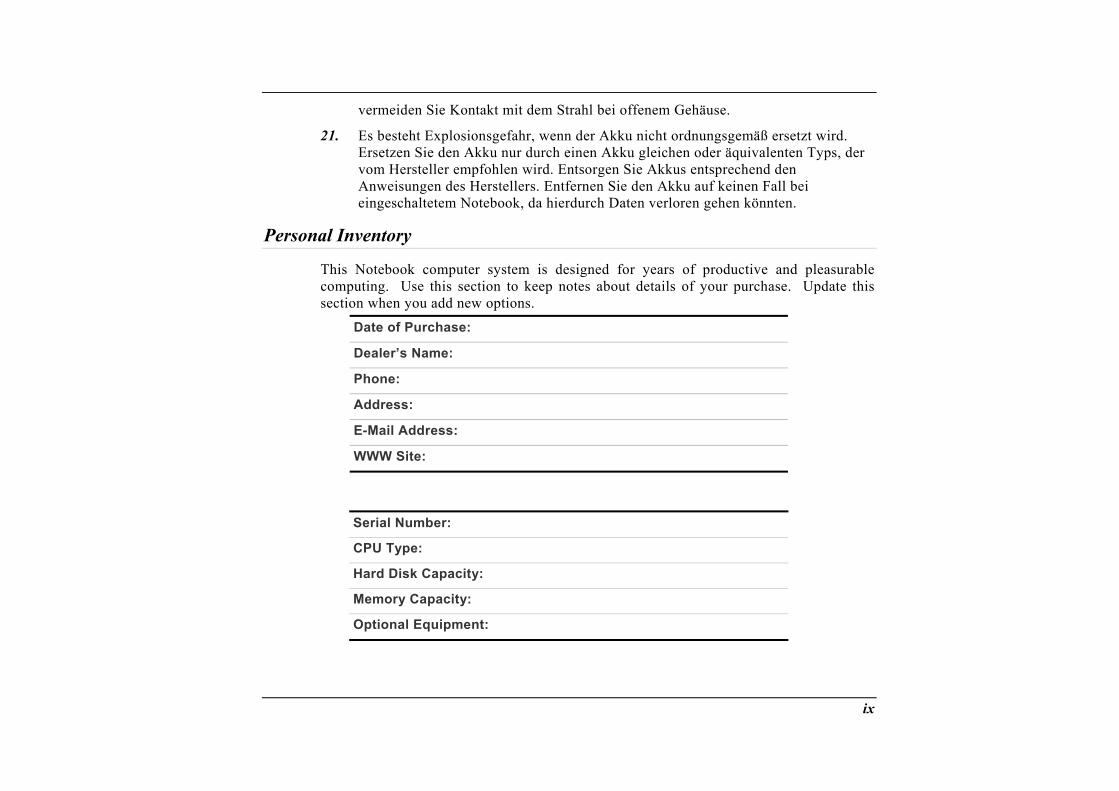
Personal Inventory
This Notebook computer system is designed for years of productive and pleasurable computing. Use this section to keep notes about details of your purchase. Update this section when you add new options.
Date of Purchase: Dealer’s Name: Phone: Address: E-Mail Address: WWW Site:
Serial Number: CPU Type: Hard Disk Capacity: Memory Capacity: Optional Equipment:
ix


Introduction
1

WARNING: There are more and more people spending large amounts of time in front of computer monitors now that scientists from many fields including anatomy, psychology, and occupational safety are involved in the study of ergonomically sound work environments.
A few tips to help you work effectively without a lot of physical discomfort: • Purchase a chair with armrests and good back support. Don't slouch when sitting; keep
your back straight. • Try to place the LCD panel or external monitor so that there is little glare from the sun
on the monitor. • Walk around the room every hour. • Every half hour look away from the computer screen for a few minutes. • Place everything that you need to work within easy reach.
Welcome to the Notebook PC
Congratulations on your purchase of the Notebook PC. Your Notebook features the latest advances in portable computing technology. The Notebook’s modular design provides maximum expandability without compromising portability. The high-performance CPU and enhanced IDE hard drive provides you with extra processing power for handling complex graphics and running large programs.
One PCMCIA slot gives you the ability to use standard PCMCIA cards, such as a LAN adapter or memory cards.
2
Getting to Know Your Computer
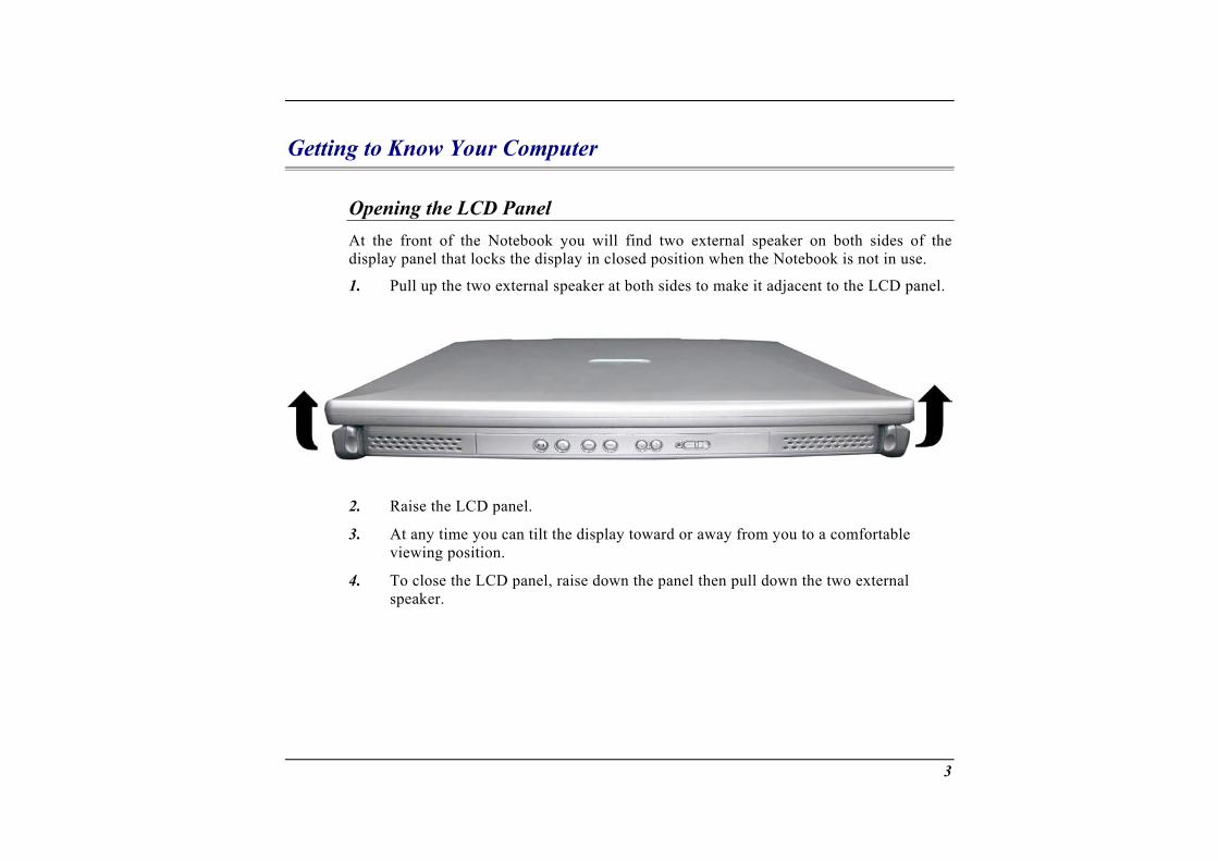
Opening the LCD Panel At the front of the Notebook you will find two external speaker on both sides of the display panel that locks the display in closed position when the Notebook is not in use.
1. Pull up the two external speaker at both sides to make it adjacent to the LCD panel.
2.
3.
4.
Raise the LCD panel.
At any time you can tilt the display toward or away from you to a comfortable viewing position.
To close the LCD panel, raise down the panel then pull down the two external speaker.
3
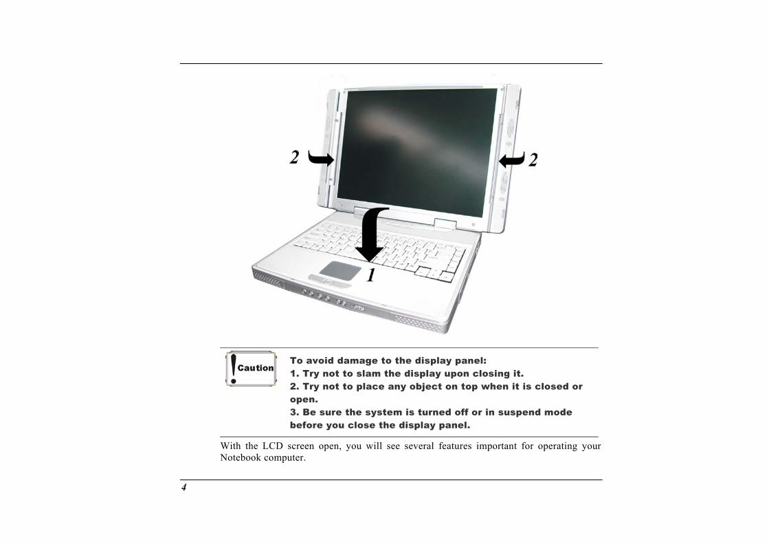
To avoid damage to the display panel: 1. Try not to slam the display upon closing it. 2. Try not to place any object on top when it is closed or open. 3. Be sure the system is turned off or in suspend mode before you close the display panel.
With the LCD screen open, you will see several features important for operating your Notebook computer.
4
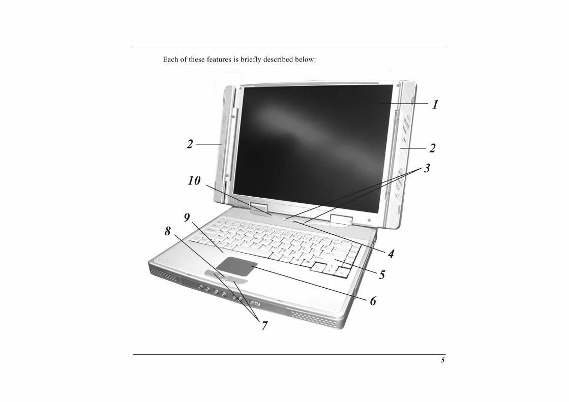
Each of these features is briefly described below:
5
1. LCD Screen Your Notebook computer is equipped with a replaceable color Liquid Crystal Display (LCD) screen that supports up to 1024 x 768 or 1400 x 1050 x 16M LCD resolution utilizing an AGP BUS. A built-in backlight allows you to comfortably view the screen even when ambient lighting is low.
2.
3.
External Stereo Speaker These two speakers provide a true stereo sound for your system.
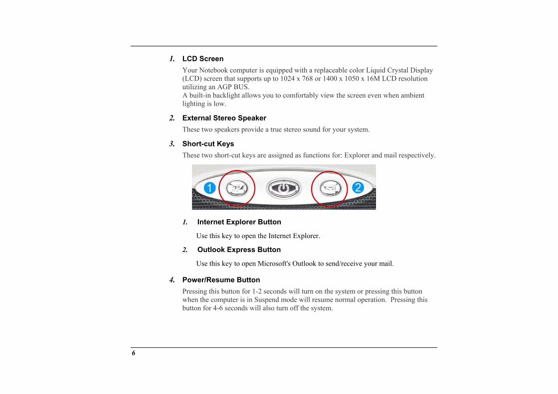
Short-cut Keys These two short-cut keys are assigned as functions for: Explorer and mail respectively.
Internet Explorer Button 1.
2.
4.
Use this key to open the Internet Explorer.
Outlook Express Button
Use this key to open Microsoft's Outlook to send/receive your mail.
Power/Resume Button Pressing this button for 1-2 seconds will turn on the system or pressing this button when the computer is in Suspend mode will resume normal operation. Pressing this button for 4-6 seconds will also turn off the system.
6
5. Keyboard Your computer has an 88-key enhanced keyboard that provides all the functions of a standard 101/102 key keyboard.
6.
7.
8.
9.
10.
TouchPad The TouchPad is hardware-compatible with the IBM PS/2 mouse and software-compatible with the Microsoft mouse.
TouchPad Buttons The buttons below the TouchPad correspond to the left and right buttons on a standard mouse. The PS/2 compatible mouse will work with the Notebook PC’s TouchPad simultaneously.
Scroll Button Use this button to scroll up and down the scrolling bar.
The Built-in Microphone The built-in microphone is located to the left of the TouchPad.
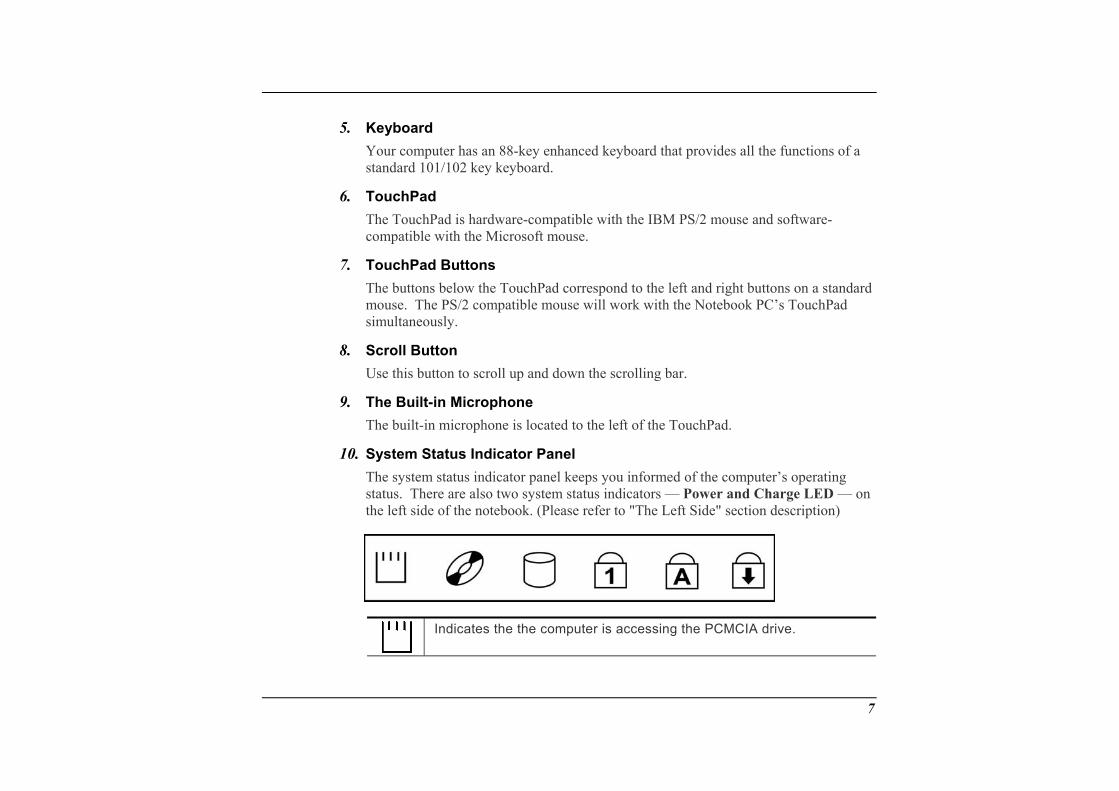
System Status Indicator Panel The system status indicator panel keeps you informed of the computer’s operating status. There are also two system status indicators — Power and Charge LED — on the left side of the notebook. (Please refer to "The Left Side" section description)
Indicates the the computer is accessing the PCMCIA drive.
7
Indicates that the computer is accessing the DVD-ROM drive.
Indicates that the computer is accessing the hard disk drive.
Indicates that the keyboard is in Num Lock mode.
Indicates when the keyboard is in Caps Lock mode. In this mode, the keyboard produces uppercase text when you press a key. When you press the Caps Lock key again, the indicator goes off and the keyboard produces lowercase text. Indicates when the keyboard is in Scroll Lock mode. Some applications will move information across the screen differently when Scroll Lock is on.
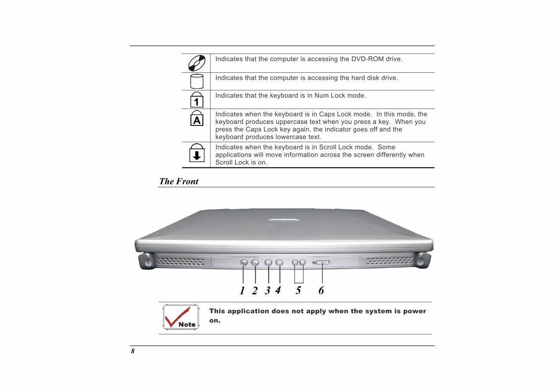
The Front
This application does not apply when the system is power on.
8
The function of this application is the same as when you are using the Windows based Media Player in playing a music CD.
1.
2.
3.
4.
5.
6.
The Play/Pause Button Press the Play button to play a selected track. Press the Pause button to freeze the music when necessary. Pressing the button again resumes playing the track from where it was frozen.
The Stop/Eject Button Press this button to stop a track. If you then press the Play button or the button of the stopped track, the track restarts from its very beginning. Press this button to open the disc tray. The button then changes to Close, waiting for you to change the disc and close the tray.
The Previous Track Button Press this button to start the previous track.
The Next Track Button Press this button to start the next track.
The Volume Buttons Press the left button to decrease the volume or the right button to increase the volume of the played track.
Audio DJ Power Button Slide this Power button to power on the audio DJ.
You will not be able to use this button to turn off the Windows based CD Player application when the notebook computer is in operation.
9
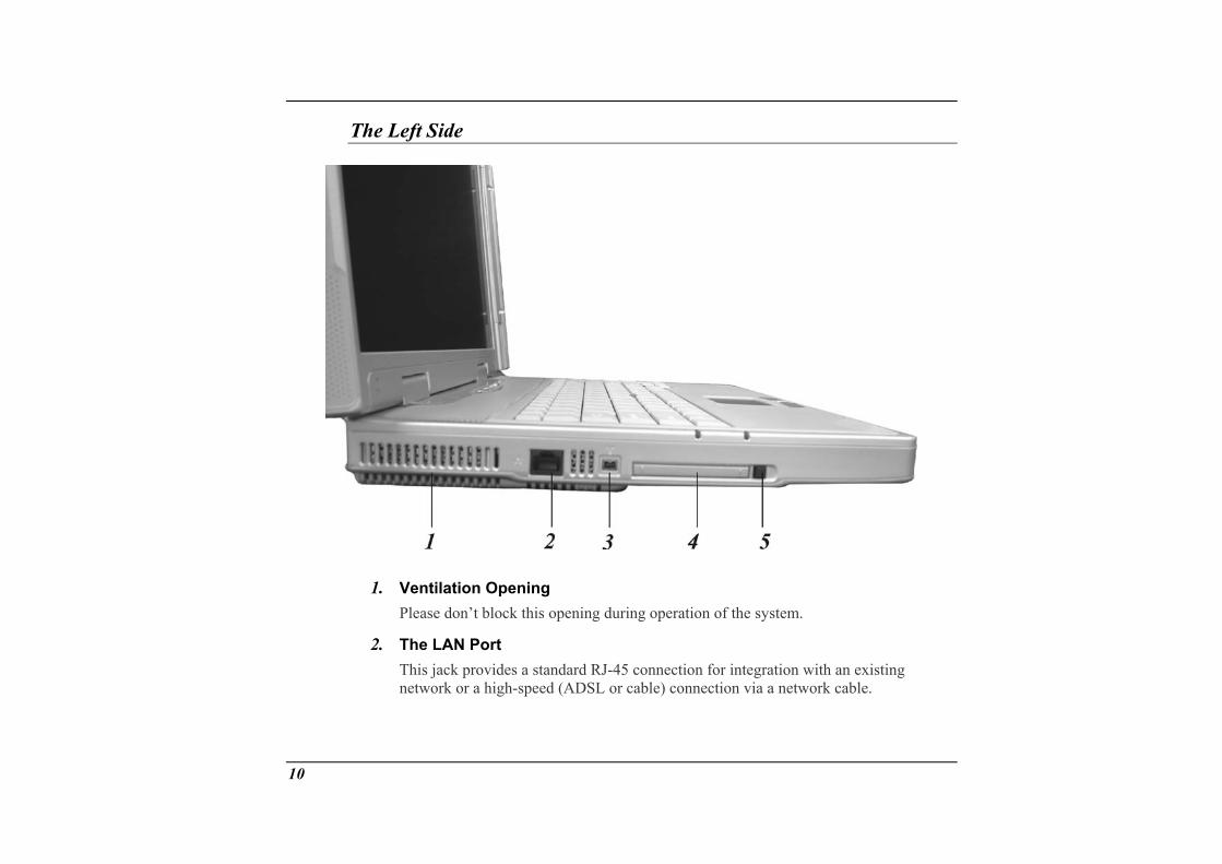
The Left Side
1.
2.
Ventilation Opening Please don’t block this opening during operation of the system.
The LAN Port This jack provides a standard RJ-45 connection for integration with an existing network or a high-speed (ADSL or cable) connection via a network cable.
10
When using a LAN, please use an EMI Shielding Cable to minimize an inteference when transmitting.
3.
4.
5.
1394 USB A fast external bus standard that supports data transfer rates of up to 400 Mbps (400 million bits per second). Can be used to connect up 63 external devices, also supports isochronous data -- delivering data at a guaranteed rate. This makes it ideal for devices that need to transfer high levels of data in real-time, such as video devices. Also supports both Plug-and-Play and hot plugging, and also provides power to peripheral devices.
PCMCIA Socket Cover Open this cover to access the PCMCIA socket. The computer’s PCMCIA socket lets you extend the capabilities of your computer by inserting PC cards.
PCMCIA Socket Button The computer has one PCMCIA type II socket
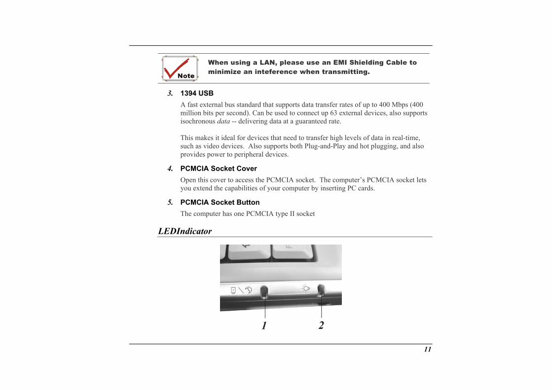
LEDIndicator
11
1. Battery Charge/Suspend This indicator will lit when the battery is in charging status. It also indicates when the system enter suspend mode.
2. Power On This indicator will lit when the notebook is powered on.
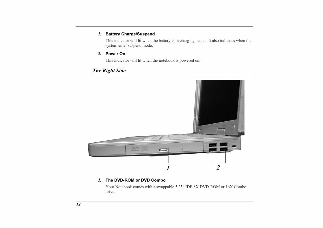
The Right Side
1. The DVD-ROM or DVD Combo Your Notebook comes with a swappable 5.25" IDE 8X DVD-ROM or 16X Combo drive.
12
2. USB Ports Your computer includes four Universal Serial Bus (USB) 2.0 port. USB2.0 is the latest development in Plug and Play technology. It will eventually replace the need for separate connectors for external keyboards, serial ports, and parallel (printer) port.
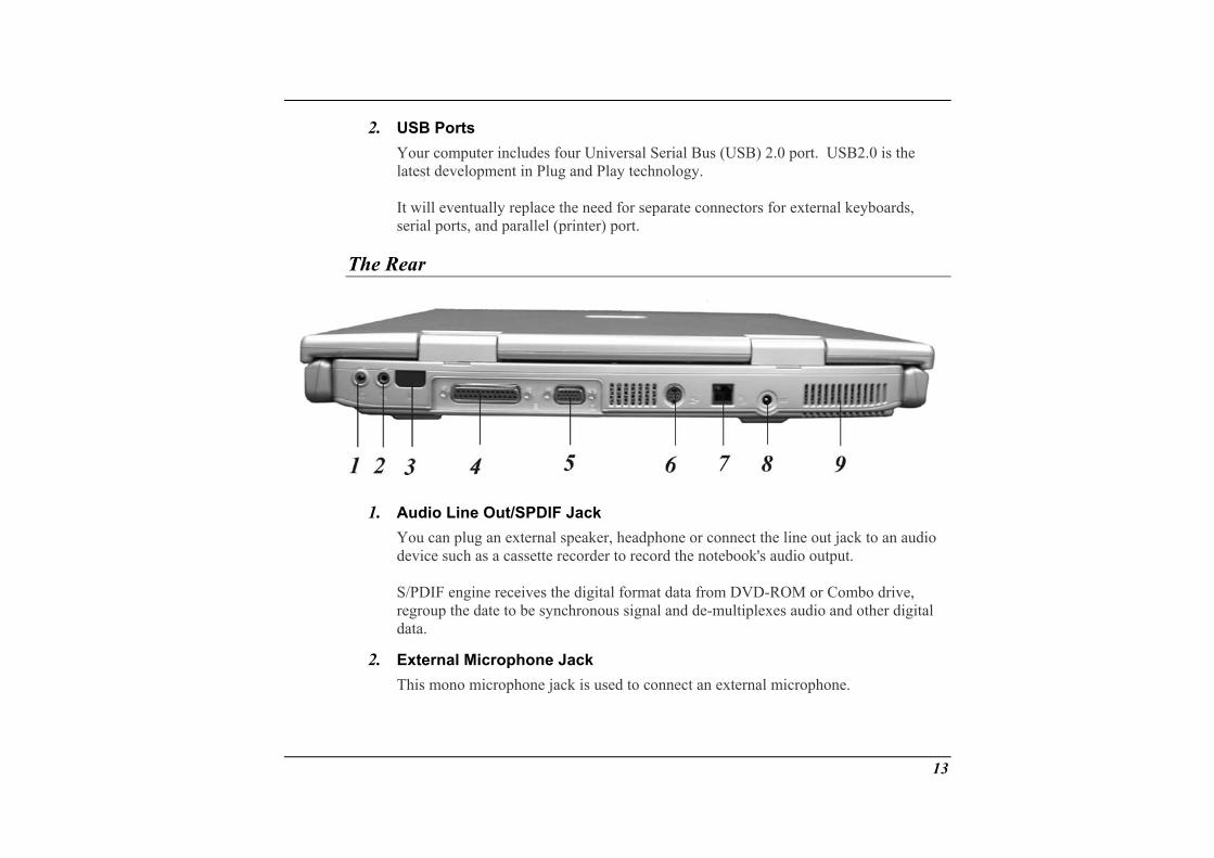
The Rear
1.
2.
Audio Line Out/SPDIF Jack You can plug an external speaker, headphone or connect the line out jack to an audio device such as a cassette recorder to record the notebook's audio output. S/PDIF engine receives the digital format data from DVD-ROM or Combo drive, regroup the date to be synchronous signal and de-multiplexes audio and other digital data.
External Microphone Jack This mono microphone jack is used to connect an external microphone.
13
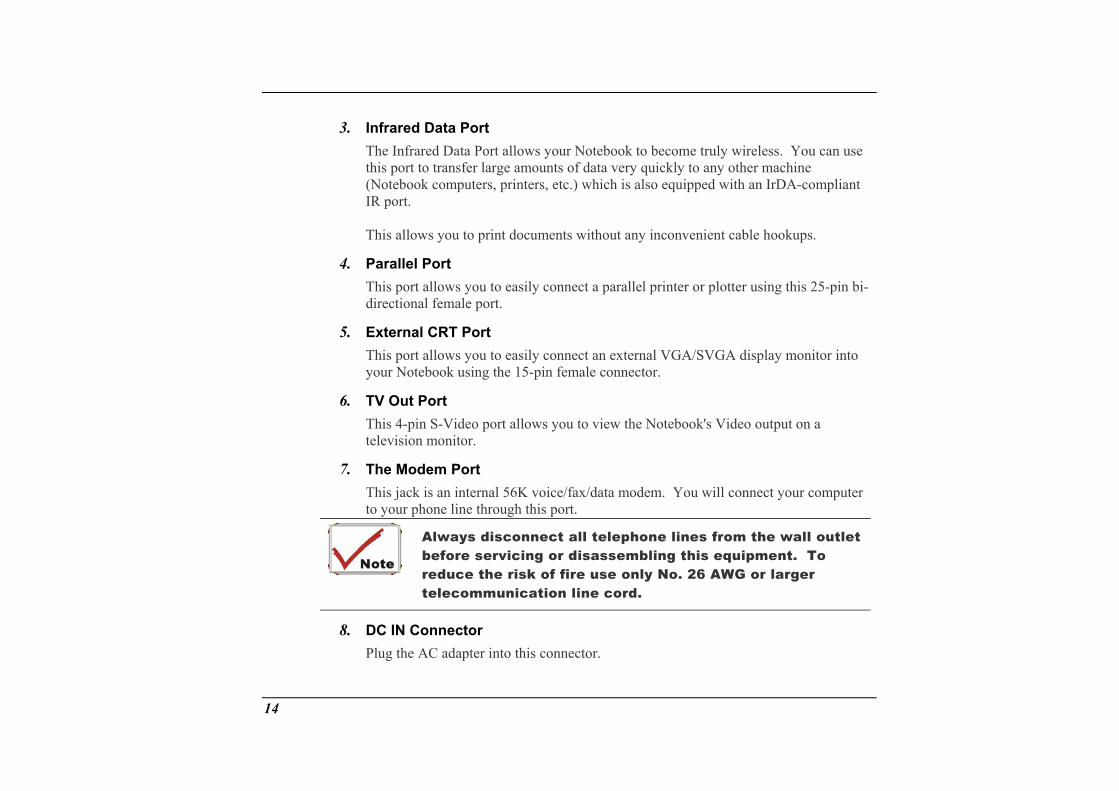
3. Infrared Data Port The Infrared Data Port allows your Notebook to become truly wireless. You can use this port to transfer large amounts of data very quickly to any other machine (Notebook computers, printers, etc.) which is also equipped with an IrDA-compliant IR port. This allows you to print documents without any inconvenient cable hookups.
4.
5.
6.
7.
Parallel Port This port allows you to easily connect a parallel printer or plotter using this 25-pin bi-directional female port.
External CRT Port This port allows you to easily connect an external VGA/SVGA display monitor into your Notebook using the 15-pin female connector.
TV Out Port This 4-pin S-Video port allows you to view the Notebook's Video output on a television monitor.
The Modem Port This jack is an internal 56K voice/fax/data modem. You will connect your computer to your phone line through this port.
Always disconnect all telephone lines from the wall outlet before servicing or disassembling this equipment. To reduce the risk of fire use only No. 26 AWG or larger telecommunication line cord.
8. DC IN Connector Plug the AC adapter into this connector.
14
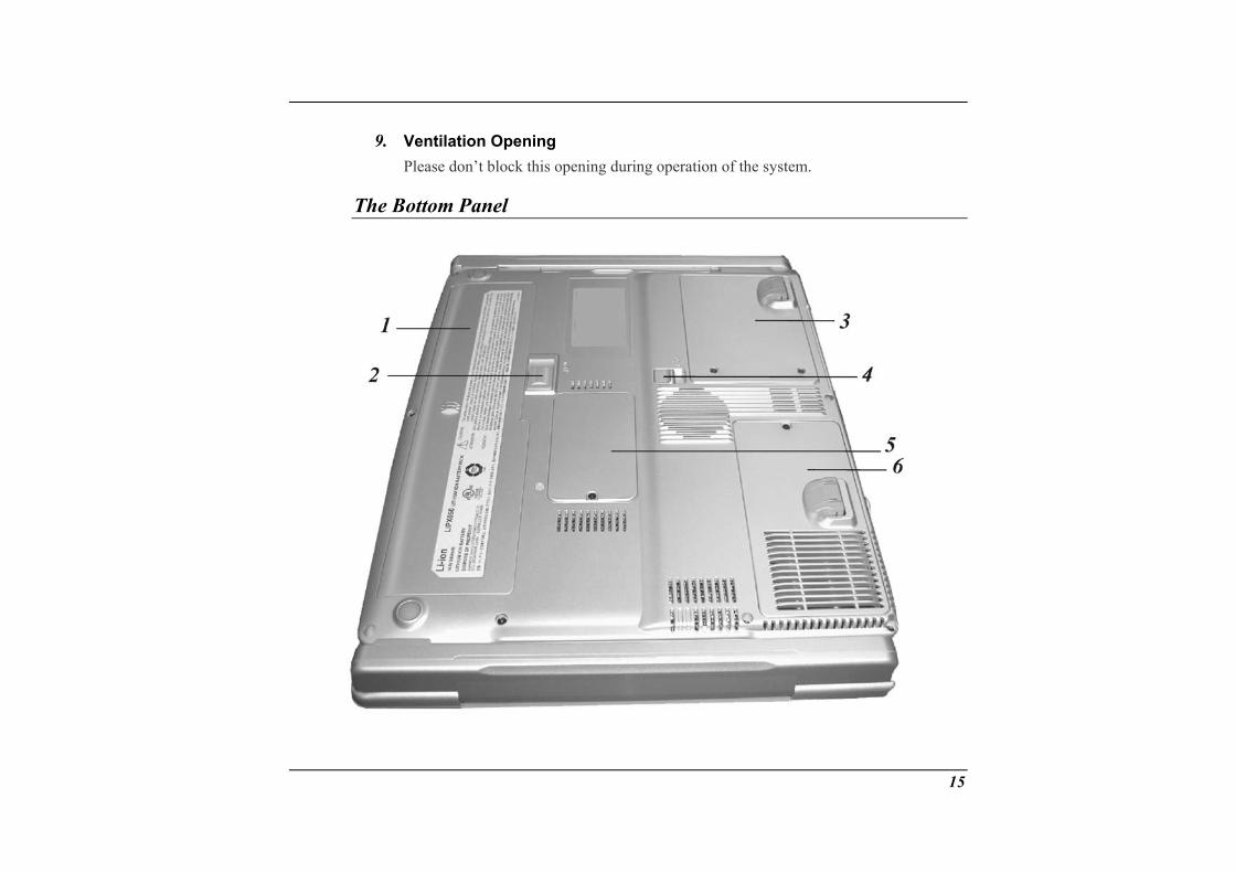
9. Ventilation Opening Please don’t block this opening during operation of the system.
The Bottom Panel
15
1. Battery Your notebook comes equipped with a factory-installed battery pack module. After the battery runs down, the module can be removed and replaced with a charged battery.
2.
3.
4.
5.
6.
Battery Release Latch Lift up this latch to release the battery from its bay.
Hard Disk Drive Your computer includes a 2.5-inch IDE hard disk drive (9.5mm in height). The notebook PC's BIOS automatically detects IDE drive types.
DVD-ROM Release Latch Push this latch to release the DVD-ROM from its bay.
Expansion Compartment This compartment will serve as an expansion to upgrade your RAM module.
CPU Compartment This compartment will serve as upgrading your system CPU.
16

Getting Started
2
Connecting to a Power Source
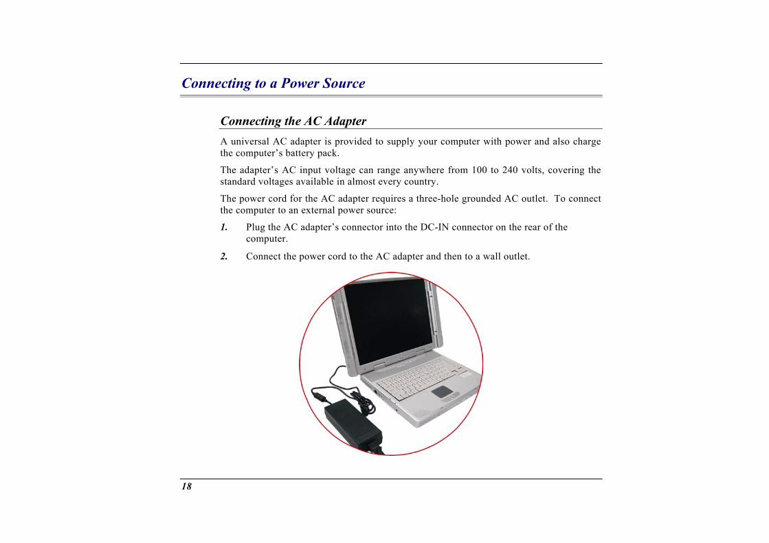
Connecting the AC Adapter A universal AC adapter is provided to supply your computer with power and also charge the computer’s battery pack.
The adapter’s AC input voltage can range anywhere from 100 to 240 volts, covering the standard voltages available in almost every country.
The power cord for the AC adapter requires a three-hole grounded AC outlet. To connect the computer to an external power source:
1.
2.
Plug the AC adapter’s connector into the DC-IN connector on the rear of the computer.
Connect the power cord to the AC adapter and then to a wall outlet.
18
The best kind of AC power source to connect your Notebook to is a UPS (Uninterruptible Power Supply). Lacking this, use a power strip with a built-in surge protector. Do not use inferior extension cords as this may result in damage to your Notebook. The Notebook comes with its own AC adapter. Do not use a different adapter to power the computer and other electrical devices.
Whenever possible, keep the AC adapter plugged into the Notebook and an electrical outlet to recharge the battery.
Never turn off or reset your Notebook while the hard disk is in use and the HDD status icon is lit; doing so can result in loss or destruction of your data. Always wait at least 5 seconds after turning off your Notebook before turning it back on; turning the power on and off in rapid succession can damage the Notebook’s electrical circuitry.
Turning On Your Notebook Computer
Turn on your Notebook by pressing the power button. Hold the button down for a second or two and release. The Power-On Self Test (POST) runs automatically.
After the POST is completed, the computer reads the operating system from the hard disk drive into computer memory (this is commonly referred to as “booting” a computer). If your OS (Operating System such as Windows ME, Windows 2000…. etc) is installed, it should start automatically.
To turn the Notebook off, save your work and close all open applications, click on Start, then Shut Down and select Shut down the computer and click "Yes" or press the power button for 4-6 seconds.
Operating on Battery Power
Your computer comes with a rechargeable battery pack that lets you operate the computer without an external power source. When the battery pack is fully charged, you can operate the computer for approximately 2 hours under the following conditions:
19
• The battery pack initially has a full charge. • No peripheral devices are installed. • The disk/DVD-ROM drives run no more than 10% of the time.
Only use batteries that are approved by an authorized dealer. All batteries are not the same and therefore should not be treated as such. Using the wrong battery could cause serious damage to your computer and yourself through toxic emissions.
Inserting and Removing the Battery Pack The battery pack should already be inserted in your Notebook computer when you unpack it. If not inserted, follow these directions:
1.
2.
Turn over the notebook with the front of the unit facing you and place it on a solid, flat surface.
Angle the battery into the bay. The front edge of the battery should slide into the grooves in the system case.
20
3.
1.
2.
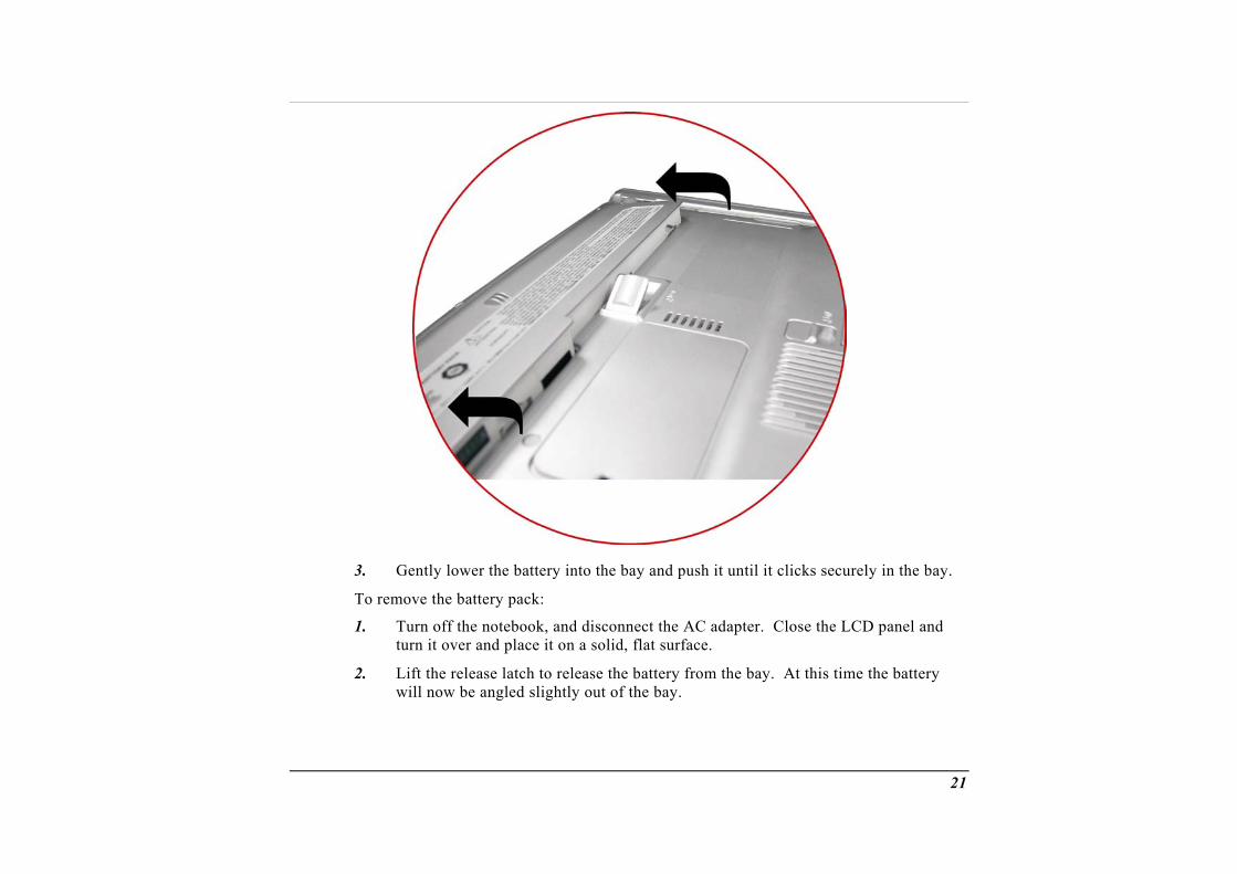
Gently lower the battery into the bay and push it until it clicks securely in the bay.
To remove the battery pack:
Turn off the notebook, and disconnect the AC adapter. Close the LCD panel and turn it over and place it on a solid, flat surface.
Lift the release latch to release the battery from the bay. At this time the battery will now be angled slightly out of the bay.
21
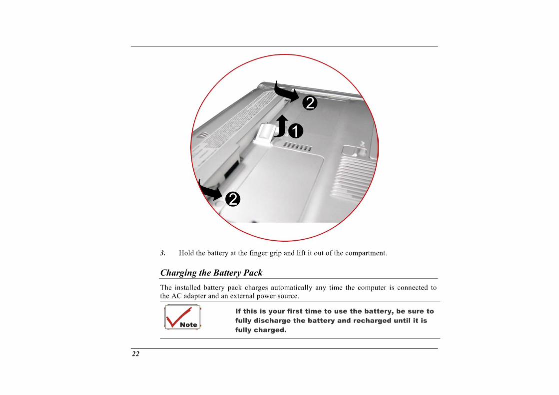
3. Hold the battery at the finger grip and lift it out of the compartment.
Charging the Battery Pack The installed battery pack charges automatically any time the computer is connected to the AC adapter and an external power source.
If this is your first tfully discharge the fully charged.
ime to use the battery, be sure to battery and recharged until it is
22

Using the Notebook
Computer
3
23
Adjusting the LCD Screen Display
The LCD screen display can be adjusted by the following key combinations. KEYS FUNCTIONS
[Fn] + [F7] Decreases the brightness level. [Fn] + [F8] Increases the brightness level. [Fn] + [F10] Use this key combination to expand your video screen or reset to its
CD screens are delicate devices that need llowing precautions: When you are not using the computer, keep
our LCD screen, use a o not put your fingers or sharp objects directlyrectly onto the display. o not press on, or store any objects on the cove
original size. [Fn] + [F12] This key combination toggles the display between the LCD, CRT,
simultaneous LCD/CRT, TV, simultaneous CRT/TV.
LCD Care L careful handling. Please pay attention to the fo• the LCD screen closed to protect it from
dust. • If you need to clean y soft tissue to gently wipe the LCD surface. • D on the surface and never spray cleaner
di• D r when it is closed. Doing so may
cause the LCD to break.
External CRT Display You can hook up an external monitor through the 15-pin CRT connector. Five configurations are available: • LCD only • CRT only
24

• Simultaneous display of the LCD scre• TV only
en and CRT monitor
You witch between these display configu essing the key combination [Fn] + or information on connecting an ext , please refer to Chapter Four.
A Tour No
• Simultaneous display of the TV screen and CRT monitor can s
[F12]. Frations by prernal display
of the tebook’s Keyboard
The Notebofunction key
ok of special s ry. Your
keyboard su ecific keys. With the s keys you will be able to access and take advantage of many of the atures of Windows software.
s depending on the application you are running.
The d) and gUp], [PgDn], [Home] and [End] keys (which are located along the right edge of th
Th pad consists of 15 keys that make number intensive input caps.
When the numeric keypad is engaged, the NumLock icon will appear in the System tivated by pressing the [Fn] + [NumLk] key. If an external
essing the NumLock key on either the Notebook or external
meric keypad while keeping the keypad on an external key use the [Fn] + [NumLk] hot key on the Notebook keyboard.
’s keyboard uses a standard QWERTY layout with the addition and an embedded numeric keypad for number intensive data ent
pports Windows by incorporating the two Windows sptwo Windowtimesaving fe
The function keys (F1-F12) on the top row of the keyboard, serve different purposes and carry out different task
cursor (arrow) keys (which are all located in the lower right corner of your keyboar the [Pe keyboard) allow you to move the active cursor of the computer to various locations
on the screen or within the document.
e embedded numeric keymore convenient. Like the [Num Lock] key, these keys are labeled in blue on the keyNumeric assignments are located at the upper right of each key.
Window. The keypad is ackeyboard is connected, prkeyboard will enable/disable NumLock of both keyboards in unison.
To disable the Notebook nuboard activated,
25
The Notebook’s Hot Key Controls KEYS FUNCTION(S)
Power Button Press this button once to power on or enter the suspend/resume mode. Press this button for more than 4 seconds to power off the system.
Internet Button Open Internet WWW Home short-cut key Email Button Open Email Reader short-cut key [Fn] + [F2] This key combination turns on/off the volume. [Fn] + [F3] Decreases the speaker volume. [Fn] + [F4] Increases the speaker volume. [Fn] + [F7] Decreases the brightness level. [Fn] + [F8] Increases the brightness level. [Fn] + [F10] Use this key combination to expand your video screen or reset to its
original size. [Fn] + [F12] This key combination toggles the display between the LCD, CRT,
simultaneous LCD/CRT, TV, simultaneous CRT/TV.
ouchPad The T
The touchpad is a rectangular electronic panel located just below your keyboard. You can use the static-sensitive panel of the touchpad and slit it to move the cursor. You can use the buttons below the touchpad as left and right mouse buttons.
26
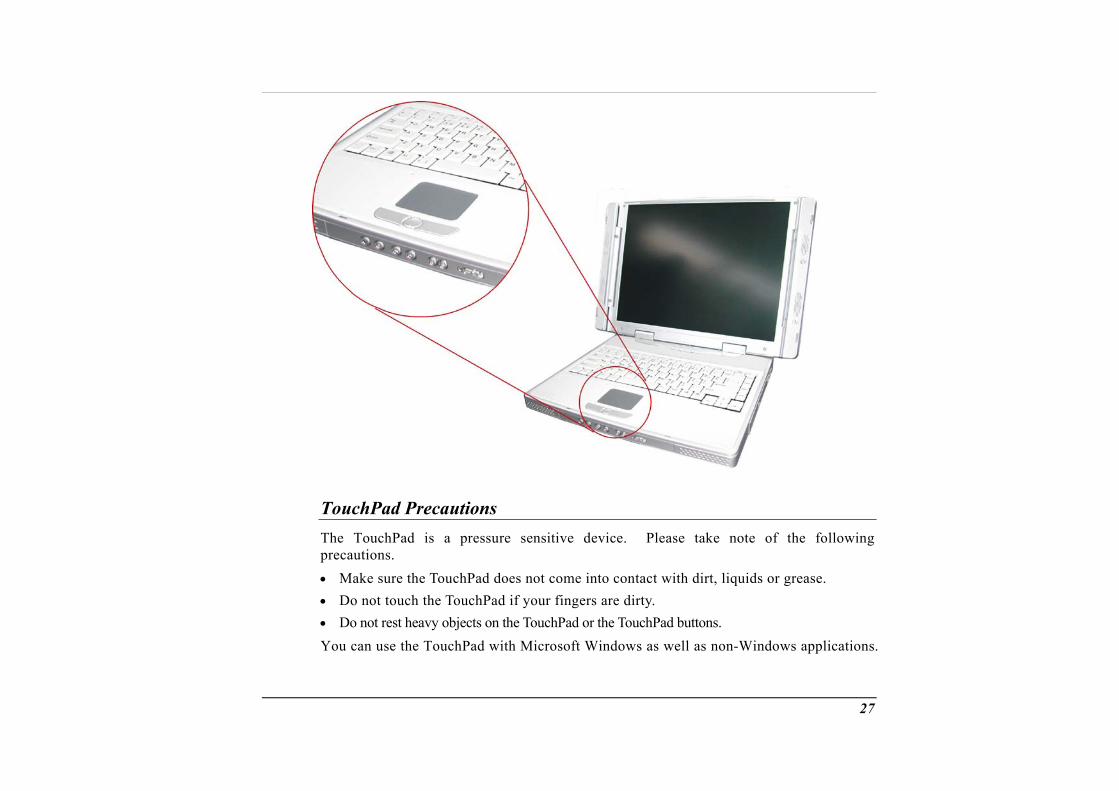
TouchPad Precautions The TouchPad is a pressure sensitive device. Please take note of the following precautions. • Make sure the TouchPad does not come into contact with dirt, liquids or grease. • Do not touch the TouchPad if your fingers are dirty. • Do not rest heavy objects on the TouchPad or the TouchPad buttons. You can use the TouchPad with Microsoft Windows as well as non-Windows applications.
27
Connecting an External Tracking Devices
The system will only enables you to use one tracking device whether it is an internexternal tracking device.
Data Storage and Retrieval
al or
Data storage and retrieval are two of the most fundamental tasks you will performworking with your computer. The Notebook is equipped with a hard disk drive (HDD). The HDD is removable allowing for easy upgrades.
Combo
when
The DVD-ROM/
Features of the DVD-ROM/Combo Module The features of the DVD-ROM/Combo drive are listed below. • The Audio Play feature allows you to play music CDs • Front panel load/unload button • Supports CD-DA, DVD-ROM mode 1 and mode 2, Multi-Session Photo CD™, CD-
I/Video CD (pcs.)
ns for Handling DVD-ROM/Combo Discs
• Low power consumption • 12.7mm height
Precautio• Always hold the disc by the edges, avoid touching the surface. • Use a clean, dry, cloth to remove dust, smudges, or fingerprints. Wipe from the center
outward. • Do not write or place objects on the surface of the disc.
28

• Store discs in a cool dry place not to damage the • Do not use benzene, thinners, or cleaners with de
disc. tergent. Only use DVD-ROM
cleaning kits. • Do not bend or drop the discs.
Loading a Disc To play a CD disc, follow the instructions listed below.
1. Push the DVD-ROM/Combo eject button on the CD drive door. Gently pull the tray all the way out.
2. Carefully lift the Dis face down (the sithe tray. Push the D
VD-ROM/Combo by the edges and make sure the shiny surface de with no writing on it). Carefully insert the DVD-ROM onto VD-ROM down gently so that it snaps onto the center ring.
is not accessing the DVD-
pull the tray all the way out.
e DVD-ROM/Combo from the tray.
3. Push the tray back into the drive.
To remove a disk, do the following:
1. Check the LED display and make sure that the computerROM drive.
2. Push the eject button and
3. Carefully pick up the CD disk by the edges and – while pressing down on the center ring – remove th
D
stretch a paper clip (or use a pin or a thinsert it into the emergency eject hole l
o not insert any foreign objects into the disc tray. If you experience difficulty when ejecting the CD disk tray,
in metal rod) and ocated on the k tray should
remove a CD from the drive when the Notebook is
right side of the front panel. The CD diseject immediately. This procedure can also be used to
powered off.
29
Removi g the DVD-ROM/Combo Drive n
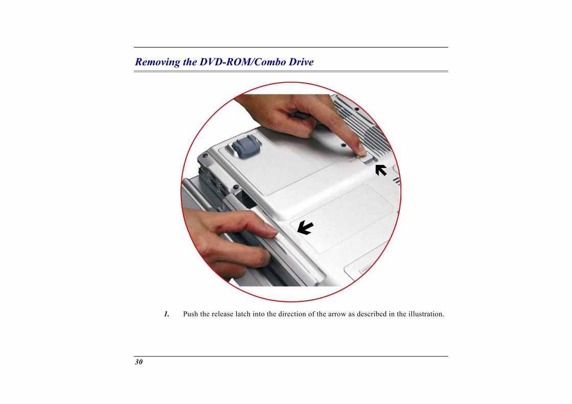
elease latch into the direction of the arrow as described in the illust1. Push the r ration.
30
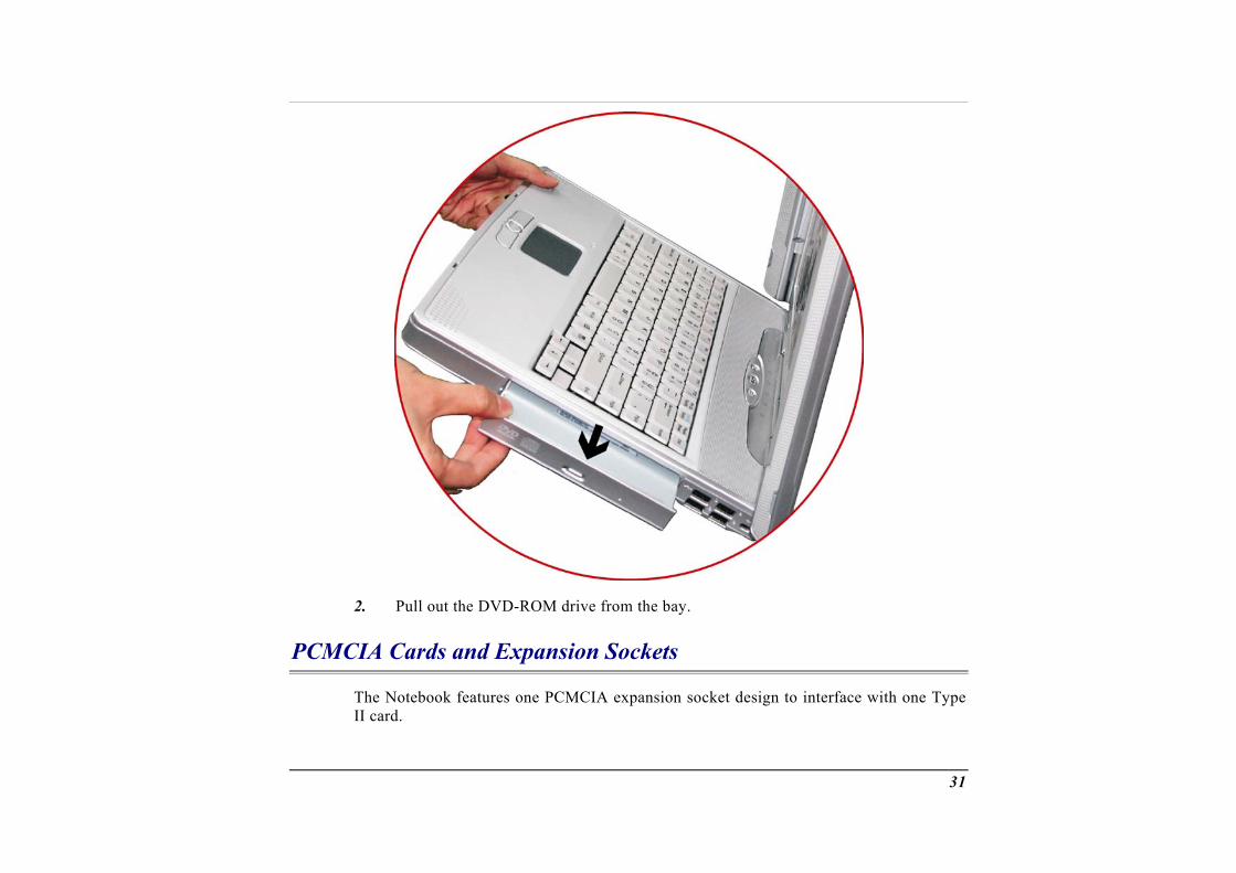
Pull out the DVD-ROM drive from the bay.
k features one PCMCIA expansion socket design to interface with one
2.
PCMCIA Cards and Expansion Sockets
The Noteboo Type II card.
31

Inserting a PCMCIA Card mputer will emit a medium tone followed by a high tone when a PC cou eject a card, the computer will emit a high tone followed by a me
ert and remove a PC card whether the computer is turned On or
these instructions to insert a PCMCIA card:
Hold the PCMCIA card with the arrow side up and the connector side toward socket.
Align the card connectors with the socket and carefully slide into the solocks into place. The system will beep once to indicate that it has detecard.
e a PC card push the eject button, the button will pop out, push ththe PCMCIA.
When inserting a Type II PC card, make sure the connector is inserted in the socket. Before ejeccard, ensure that it is not being accessed by the SFor example, if the message “Write protect error wriDrive x” is displayed, the user has to change the wriprotect switch setting on the memory card. To chathe switch setting, (a) eject the card, (b) change switch setting, and (c) re-insert the card.
The co ard is inserted. When y dium tone. You can ins Off.
Follow
1. the
2. cket until it cted the PC
To remov e button again to eject
ting a PC ystem.
ting te
nge the
Alway the wall outlet before servicing or of fire, use only No. 26 AWG or larger
s disconnect all telephone lines from disassembling this equipment. To reduce the risktelecommunication line cord.
32
Power Saving Modes
This section contains information on the Notebook’s power system, including the AC Adapter, the battery system, recharging the battery, and tips for conserving battery power.
The power system is comprised of two parts, the AC Adapter and the battery system. The tlet to the DC power required by the
comp
The
AC Adapter converts AC power from a wall ouuter.
Battery Power System y charged pack will provide approximately 2 hours of battery life depending on yo
stem confA full ur sy iguration application it runs.
olbar to make sure the battery is fully charged.
S at the Windows Battery Ch off st ble
Removing th
Before using the computer on battery power for the first time, check the battery status icon on the Windows To
ee Battery St icon.
ate. If poss
us later in this section for a description and explanation ofarging the battery takes about 3 hours to charge when the system is in , always charge the battery completely.
e Battery Pack
i
attery pack from its compartment, please refer to Chapter Two, Insehe Battery Pack.
To remove the b rting and Removing t
Preparing the Battery Pack for Use Before using the battery pack for the first time, the Smart Battery IC within the battery pack should be calibrated in order to get accurate reporting of remaining battery life status.
To calibrate the battery pack follows the instructions below:
1. Insert the battery into the battery compartment and turn on the Notebook. If the battery is completely without power go to the next step.
33
Otherwise, let theard.
he battery run down until the battery low-low warning beeps are
The system will automatically enter Suspend mode.
. You can now connect the AC adapter.
ibrated properly.
2. Turn the Notebook off. Connect the AC adapter and let the battery fully recharge. When the battery charge indicator turns off, the battery is fully charged.
3. Turn On the notebook, let the battery run down until the battery is in low-low state and you hear a warning beeps. The system will automatically enter the Suspend mode
4. The battery pack is now cal
In general, using the battery until the low-low battery-warning indicator appears and fully recharges the battery each time (full discharge/charge cycle) will ensure the accurate reporting of the battery gauge status.
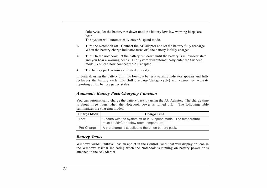
Automatic Battery Pack Charging Function You can automatically charge the battery pack by using the AC Adapter. The charge time is about three hours when the Notebook power is turned off. The following table summarizes the charging modes:
Charge Mode Charge Time Fast 3 hours with the system off or in Suspend mode. The temperature
must be 25°C or below room temperature. Pre-Charge A pre-charge is supplied to the Li-Ion battery pack.
Battery Status Windows 98/ME/2000/XP has an applet in the Control Panel that will display an icon in the Windows taskbar indicating when the Notebook is running on battery power or is attached to the AC adapter.
34
This applet also displays a meter that indicates how much charge is remaining in the battery.
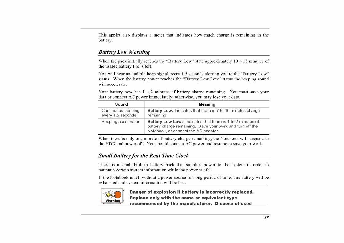
ry Low Warning BatteWhen the us
You w ” status d will acce
Your b arge remaining. You must save your
the pack initially reaches the “Battery Low” state approximately 10 ~ 15 minutes ofable battery life is left.
ill hear an audible beep signal every 1.5 seconds alerting you to the “Battery Low. When the battery power reaches the “Battery Low Low” status the beeping soun
lerate.
attery now has 1 ~ 2 minutes of battery chdata or connect AC power immediately; otherwise, you may lose your data.
Sound Meaning Continuous beeping Battery Loevery 1.5 seconds
w: Indicates that there is 7 to 10 minutes charge remaining.
Beeping accelerates Battery Low Low: Indicates that there is 1 to 2 minutes of battery charge remaining. Save your work and turn off the Notebook, or connect the AC adapter.
When there is only one minute of battery charge remaining, the Notebook will suspend to the HDD and power off. You should connect AC power and resume to save your work.
S l Battery mal for the Real Time Clock here is a s built-in battery pack that supplies power to theT mall system in order to
maintain certain system information while the power is off.
left without a power source for long period of time, this battery will be If the Notebook isexhausted and system information will be lost.
Danger of explosion if battery is incorrectly replaced. Replace o
nly with the same or equivalent type
recommended by the manufacturer. Dispose of used
35
batteries according to the manufacturer's instructions. Never remove the battery pack while the power is on as this may result in data loss when the system loses power.
Resetting the System After installing a software application package, you may be prompted to reset the system
lock up the Notebook.
r some reason, pressing ton powers the Notebook off.
A ight
to load the changed operating environment. To reset the system, or “reboot,” press the [Ctrl] + [Alt] + [Delete] keys simultaneously. This is known as “warm boot.” This key combination acts as “software” reset switch when you encounter hardware or software problems, which
If this key combination does not shut down the Notebook, you can reset the Notebook by using the Notebook’s power button. Should the Notebook lock up fo
this but
djusting the Br ness To adjust the brightness the lower left hand corner of reduce the brightness or
on the LCD screen, press and hold down the [Fn] key inthe keyboard and press the [F7] key to
[F8] to increase the brightness.
36

4Desktop Operation
ur notebook is capable of providing you with efficient and productive mobile computing, it also has the speed and capacity to service as a desktop system.
This chapter discusses those functions of your notebook that are typical of desktop
external microphone can be connected to the microphone jack. dphones can be connected to the Notebook’s audio-out jack.
External audio devices can be connected to the Line in jack. All
systems.
Audio
The Multimedia Sound System The Notebook’s built-in audio capabilities allow you to take advantage of a wide range of education and entertainment multimedia software. The Notebook is equipped with two internal stereo speakers, a microphone, and input audio ports for external audio units.
An External speakers or hea
audio features are software controlled. The Notebook’s multimedia sound system includes the following features: • Supports Windows Sound System compatibility • Full Duplex operation • Dynamic filtering reduces noise and distortion rate • 16-bit digitized audio playback • A built-in microphone for convenient recording • Two built-in stereo speakers • Digitized audio recording through the Notebook’s built-in microphone or any external
source
38
Audio Volume Control The Notebook is equipped with hot-key volume controls: Pressing the [Fn] + [F3] hot-key combination decreases the audio output volume, press the [Fn] + [F4] hot-key combination increases the audio output volume.
Audio Software Your notebook comes equipped with anwith quality audio sound through th
integrated sound system capable of providing you e built-in speakers or through external speakers
connected via the system ports.
Sound Recording Your system allows you to record sounds and store them as files using the microphone via the microphone jack on the rear of the notebook computer. Check the Windows Help and Support Center in Windows for information on using the various elements in sound recording.
Control
For a high-quality sound, click on the "Volume Control" at creen. From the Volume
windows, click on the "Advanced" tab, click and item.
the lower right end of your s
select the "Microphone Boost"
Playing Sound Files Your notebook can play audio files stored in MIDI, WAVE or MP3 file format. Check the a Pla
Help and Support Center in Windows for information on the functions of the Mediyer.
39

External Speakers and Microphone The sound system is capable in providing high-quality sound to external speakers and receiving and processing sounds from an external microphone or external sound source.
Connecting Peripheral Devices
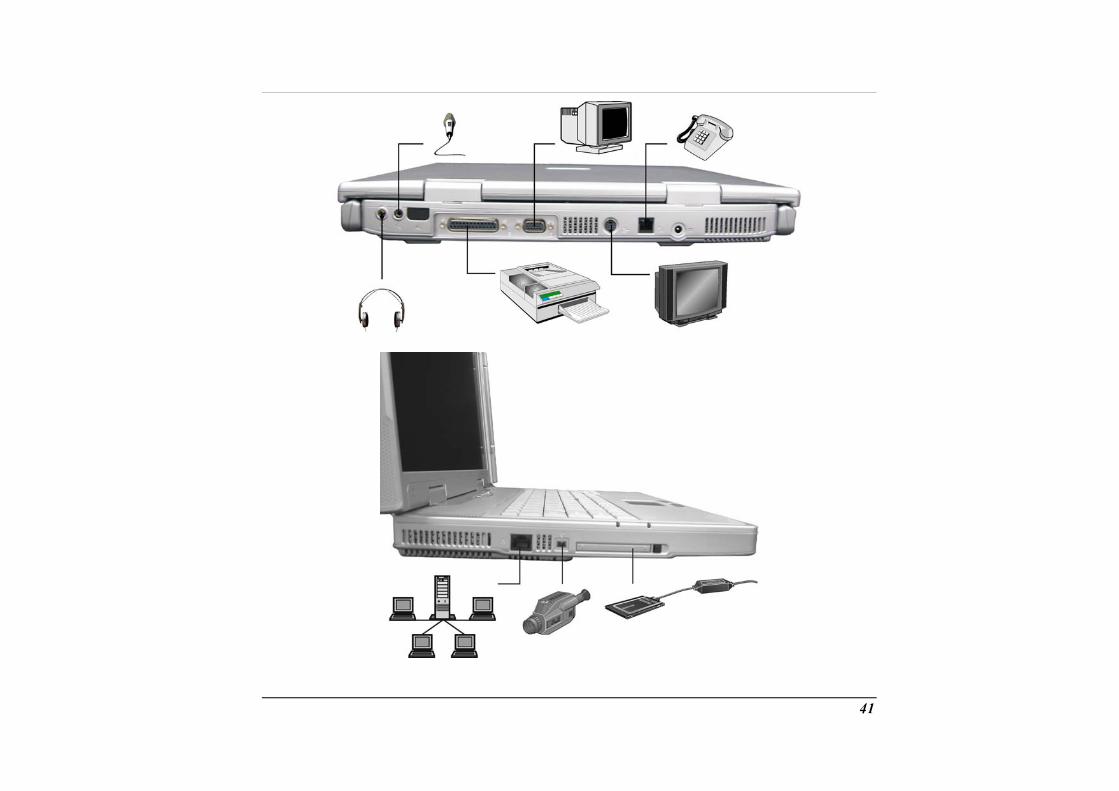
To expand your computing capabilities, you can add a variety of external devices to your computer. You may, for example, want to add a mouse, modem, or a printer.
The computer is equipped wit(printer) port, a serial port,
h several interface ports, including an enhanced parallel and USB ports. These are provided as a means of connecting
e computer.
Connect peripheral devices to the computer's interface ports as shown below:
peripheral devices to th
40
41

42

Running BIOS Setup
5
Introduction
The BIOS (Basic Input and Output System) Setup program is a menu driven utility that to reflectck on, the, you can
enables you to make changes to the system configuration and tailor your system installed hardware or alter system performance. When the Notebook is turned ba system is configured with the values stored in CMOS. With easy-to-use menus configure such items as:
• Hard drives and peripherals • Boot up Drive Sequence • Password protection • Power Management Features
The settings made in Notebook performs.
Navigating through
the BIOS Setup program intimately affect how the
BIOS Setup
it as easy to use one to switch back us value.
The Setup program has been designed to make as possible. If you accidentally make a setting and don’t know which to, the Setup program has a hot key that allows you to return to the previo
Accessing the BIOS Setup Program
To access the BIOS Setup program, press the F2 key after the Notebook has run through its POST.
Item Specific Help On the right side of the Setup screen is an area labeled Item Specific Help. This area will list navigation key shortcuts and information that is specific for the item that you are currently editing.
44

The Menu Bar
The top of the screen has a menu bar with the following selections: • Main - Use this menu to make changes to the basic system configuration. • Advanced - Use this menu to enable and make changes to the advanced features
available on your system. • Security - Use this menu to set a password. The password allows boot up and
setup menu. onfigure the default system device used to locate and load
and for booting up the Notebook. e current menu or specify how to exit the Setup
To access the menu bar items, press the right or left arrow key on the keyboard until the
The Legend Bar
controls access to the BIOS • Boot - Use this menu to c
the Operating System• Exit - Use this menu to exit th
program.
desired item is highlighted.
At the bottom of the Setup screen you will notice a legend bar. The keys in the legend bar allow you to navigate through the various setup menus.
The following table lists the keys found inand functions.
the legend bar with their corresponding alternates
Legend Key Alternate Key Function F1 Alt + H Displays the General Help window. It can be enabled
from anywhere in the BIOS. Esc Alt + X Jumps to the Exit menu or returns to the Main menu from
a submenu. ← Selects the menu item to the left.
→ Selects the menu item to the right.
45
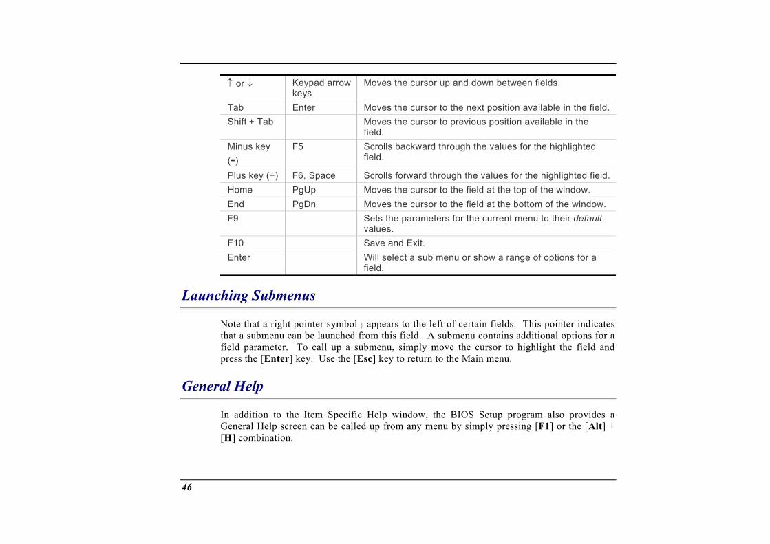
↑ or ↓ Keypad arrow keys
Moves the cursor up and down between fields.
Tab Enter Moves the cursor to the next position available in the field.Shift + Tab Moves the cursor to previous position available in the
field. Minu e(-)
ld.
s k y F5 Scrolls backward through the values for the highlightedfie
Plus y field.ke (+) F6, Space Scrolls forward through the values for the highlightedPgUp Moves the cuHome rsor to the field at the top of the window.
End PgDn Moves the cursor to the field at the bottom of the window. Sets the parameters for F9 fault the current menu to their de
values. F10 Save and Exit. Enter Will select a sub menu or show a range of options for a
field.
Launching Submenus
Note that a right pointer symbol appears to the left of certain fields. This pointer indicates that a submenu can be launched from this field. A submenu contains additional options for a
r] key. Use the [Esc] key to return to the Main menu.
Genera
field parameter. To call up a submenu, simply move the cursor to highlight the field and press the [Ente
l Help
ad the Item Help window, the BIOS Setup program also provides d up from an
H]
In dition to Specific a General Help screen can be calle y menu by simply pressing [F1] or the [Alt] + [ combination.
46
Use the ntire he
[PgUp] ys through the e lp docu he to go to the la ge. To exi elp windo
Save Changes and Exit the Setup Program
and [PgDn] kement. Press t
or the up and down arrow keys (↑↓) to scrollHome key to display the first page, press End
st pa t the h w, press the [Enter] or the [Esc] key.
fer to the exiting th
me this chapter for detailed information on saving change
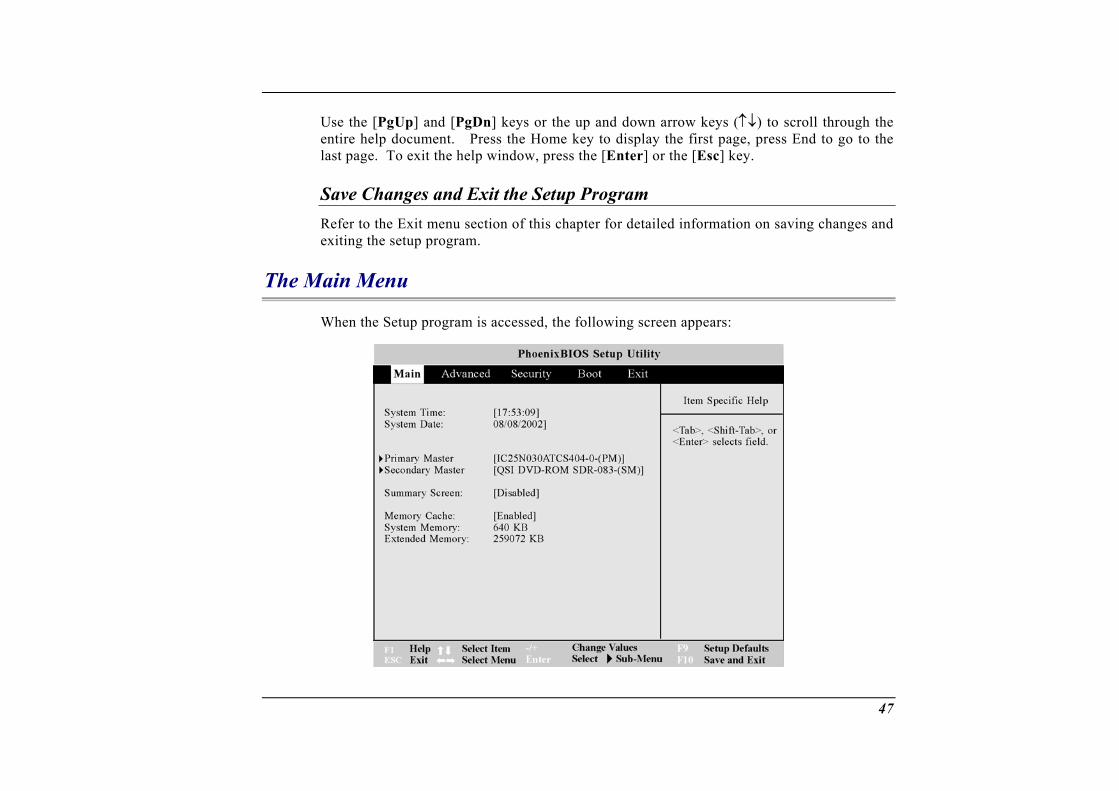
The Main Menu
ed, the following screen appears:
Re Exit nu section of s and e setup program.
When the Setup program is access
47
System Time
Sets your system to the time that you specify. The format is hour, minute, second. Use the [Tab] or [Shift] + [Tab] keys to move between the hou
r, minute, and second
fields.
year. Use the [Tab] or [Shift] + [Tab] keys to move between the nth, day, and year fields.
Primary Master
System Date
Sets your system to the date that you specify (usually the current date). The format is month, day, mo
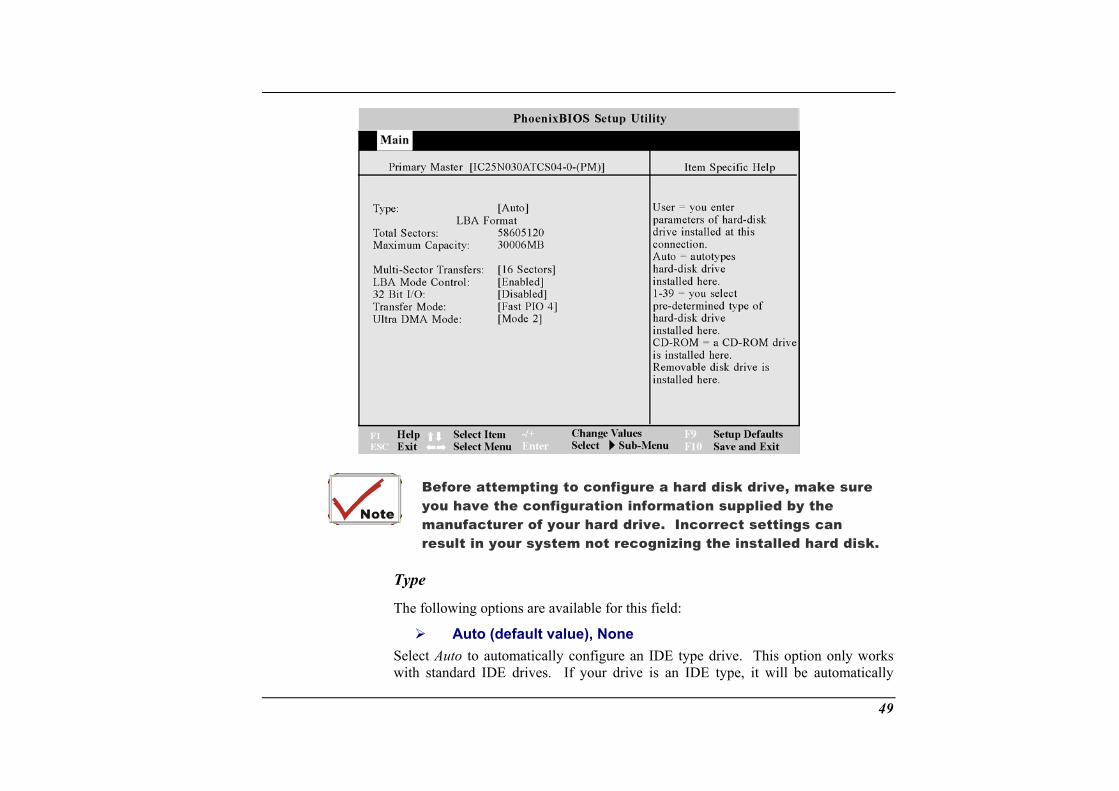
This fiel To configure a hard disk d
Prim
Pressing th
d is used to configure the IDE Hard Disk installed in the system. rive, move the cursor to highlight the Primary Master field:
ary Master [IC25N040ATCS04-0- (PM)]
e [Enter] key at this point will reveal the Primary Master submenu:
48
49
with standard IDE drives. If your drive is an IDE type, it will be automatically
Before attempting to configure a hard disk drive, make sure you have the configuration information supplied by the manufacturer of your hard drive. Incorrect settings can result in your system not recognizing the installed hard disk.
Type
The following options are available for this field:
Auto (default value), None Select Auto to automatically configure an IDE type drive. This option only works
recognized and properly configured.
If automatic detection is successful, the correct values will be filled in for the remaining fields on this submenu. If no drive is installed or if you are remdrive and not replacing it, select None.
DVD-ROM if a DVD-ROM is installed as the IDE Adapter 0 Master.
To configure a drive that is not an IDE type drive, if it is User. Manually enter the number of cylinders, heads and sectors per track for your drive. Refer to yourdrive’s documentation or look on the drive if you need to obtain this information.
ATAPI Removable if the drive is an ATAPI type drive that supports high-capacity storage diskettes. This option would be used in the event that you have swappeDVD-ROM for an ATAPI type removable drive.
Total Sectors
This field configures the drive’s number of sectors per track. If the ssuccessfully detected the drive automatically, there is no need to adjust this field. In order to make changes to this field, the Type field must be set to User.
Maximum Capacity
oving a
d the
ystem has
is field gives the maximum formatted capacity of the hard disk drive. This is a pl
ul
er rted by the drive. This field can also be configured manually. Note that when
this field is automatically configured, the set value may not always be the fastest
Ref t h your hard drive to determine the optimal
Thdis
M
ay only field.
ti-Sector Transfers
This option automatically sets the number of sectors per block to the highest numbsuppo
value for the drive.
er to he documentation that came witvalue and set it manually. In order to make changes to this field, the Type field must be set to User. Configuration options are:
50
Disabled, 2 Sectors, 4 Svalue)
ectors, 8 Sectors, 16 Sectors (default
addressing of he hard drive without regard for
this option speeds up communication between the CPU and the IDE is option supports PCI local bus only. ISA bus is not supported. Set
using enhanced I/O transfer modes (PIO) Modes.
to provide the optimum transfer mode. Configurations are:
LBA Mode Control
When enabled, this option uses 28-bitcylinders, heads, and sectors.
Note that Logical Block Access may decrease the access speed of the hard disk.
In order to make changes to this field, the Type field must be set to User. Configuration options are:
Disabled, Enabled (default value)
32 Bit I/O
When enabled,controller. Ththe Type field to Auto to provide the optimum transfer mode. Configuration options are:
Disabled, Enabled (default value)
Transfer Mode
When enabled, this option speeds up communication between the system and the IDE controller by
Set the Type field to Auto
Standard, Fast PIO 1, Fast PIO 2, Fast PIO 3, Fast PIO 4, FPIO 3 / DMA 1, FPIO 4 / DMA 2
Ultra DMA Mode
When enabled, this option speeds up data transfer to and from the drive. In order to make changes to this field, the Type field must be set to User.
51
Set the T pe field to Auto to provide the optimum transfer mode. Configurations a
Disably re:
ed, Mode 0, Mode 1, Mode 2 (default value), Mode 3,
ys to make changes to this submenu, press the [Esc] key to
Second
Mode 4 After using the legend keexit back to the Main menu.
ary Master The value arrowhead field contains a submenu. The submenu is used to configure a DV O
To configur OM, move the cursor to highlight the Secondary Master field, and press the [E The Secondary Master submenu screen will appear. When the Type field is set set to “UseMaster sub
After using legend keys to make your selections to this submenu, press the [Esc] key to exit back to the n
in this field indicates the type of your Notebook’s DVD-ROM drive. The icon indicates that this
D-R M installed in the system.
e a DVD-Rnter] key.
to “Auto”, only the 32 Bit I/O and Ultra DMA Mode fields are available. When r” the fields and options on this submenu are the same as the IDE Adapter 0
menu described above.
the Mai menu.
52
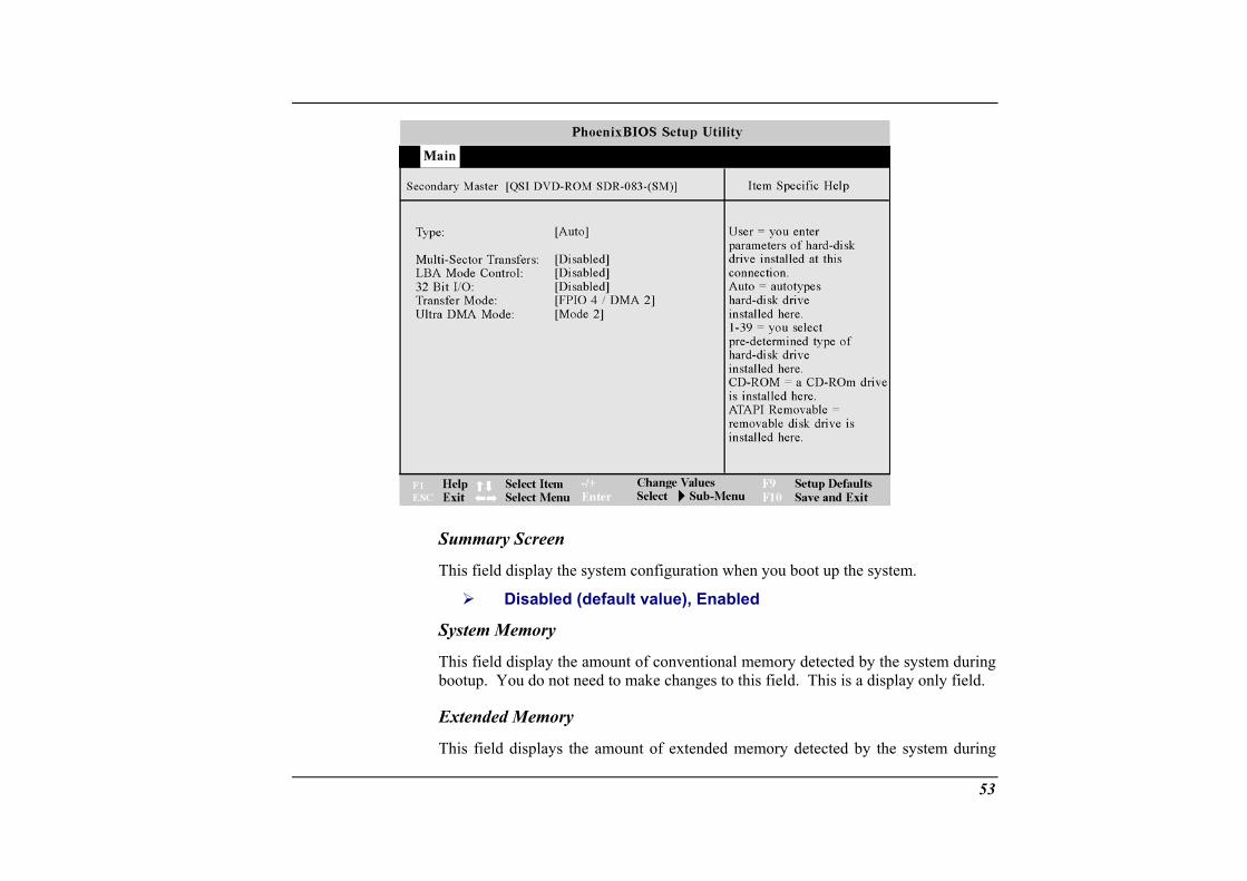
Summary Screen
This field display the system configuration when you boot up the system.
Disabled (default value), Enabled
System Memory
This field display the amount of conventional memory detected by the system during bootup. You do not need to make changes to this field. This is a display only field.
Extended Memory
53
This field displays the amount of extended memory detected by the system during
boot-up. You do not need to make changes to this field. This is a display onl
Advanced from the menu bar displays the advanced menu:
y field.
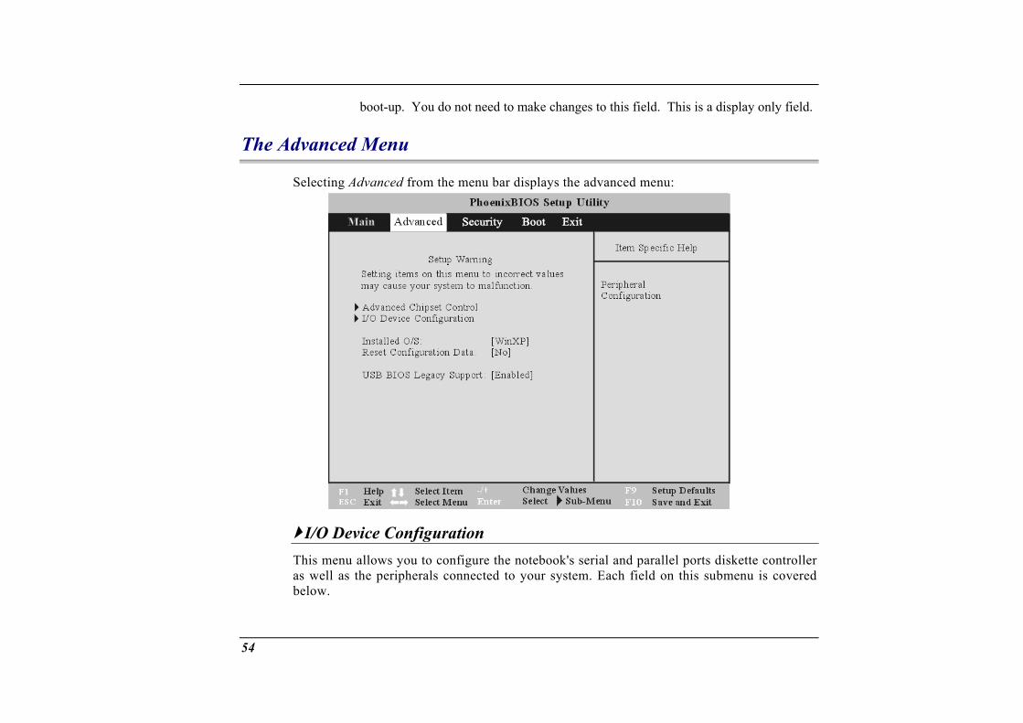
The Advanced Menu
Selecting
I/O Device Configuration This menu as well as th d below.
allows you to configure the notebook's serial and parallel ports diskette controller e peripherals connected to your system. Each field on this submenu is covere
54
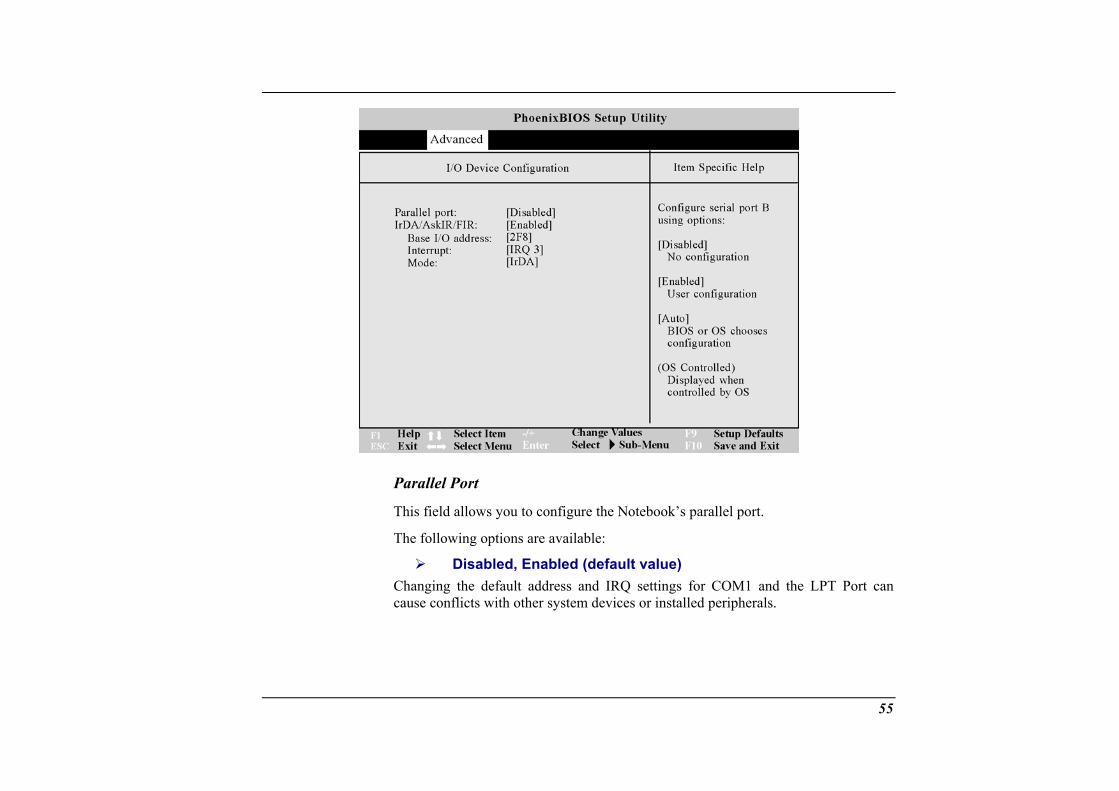
Parallel Port
This field allows you to configure the Notebook’s parallel port.
The following options are available:
Disabled, Enabled (default value) ddress and IRQ settings for COM1 and the LPT Port can
stem devices or installed peripherals. Changing the default acause conflicts with other sy
55
IrDA/FIR
This field allows you to enable or disable the Notebook's Fast Infrared (FIR) communication module. The following configuration options are available:
Disabled, Enabled (default value)
Base I/O Address
When the Parallel Port is set to Enabled, the "Base I/O Address" field available and you can set the parallel port's I/O address. Available configuratio
3F8, 2F8 (default value), 3E8, 2E8
Interrupt
Use this option to choose the Interrupt for the Sound chip. Available configurationsare:
IRQ 3 (default value), IRQ 4
Mode
This field allows you to configure the notebook's Fast Infrared (FIR) co
becomes ns are:
mmunication module. Available configurations are:
IrDA, FIR (default value)
The Security M
enu
The Notebook s advan u to set a password to prevent unauthorize
’ ced system of security allows yod access to system resources, data, and the BIOS Setup Program.
56
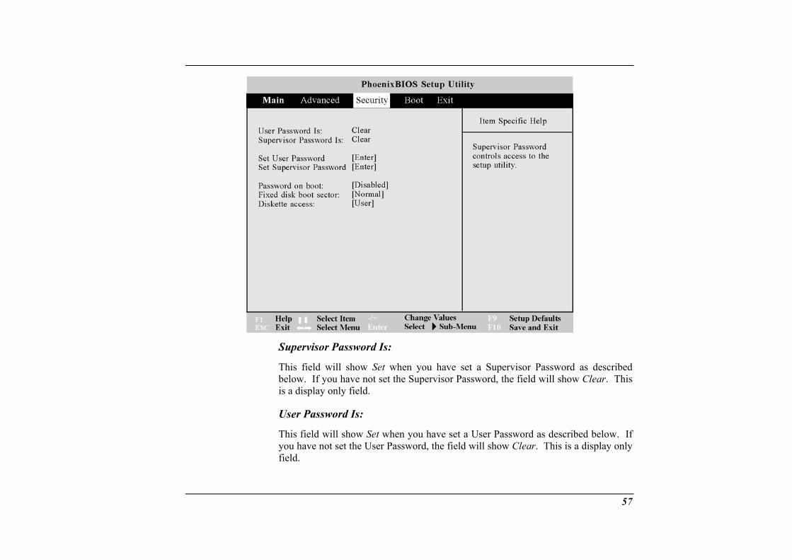
Supervisor Password Is:
This field will show Set when you have set a Supervisor Password as described If you have not set the Supervisor Password, the field will show Clear. This
only field.
This field will show Set when you have set a User Password as described below. If you have not set the User Password, the field will show Clear. This is a display only field.
below. is a display
User Password Is:
57
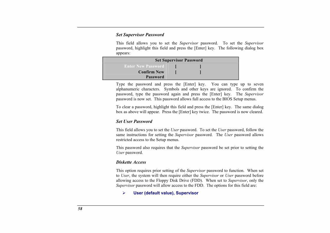
Set Supervisor Password
This field allows you to set the Supervisor password. To set the password, highlight this field and press the [Enter] key. The following appears:
Supervisor dialog box
Set Supervisor Password Enter New Password [ ]
Confirm New Password
[ ]
Type the password and press the [Enter] key. You can type up to seven alphanumeric characters. Symbols and other keys are ignored. To confirm the password, type the password again and press the [Enter] key. The password is now set. This password allows full access to the BIOS Setup m
To clear a password, highlight this field and press the [Enter] key. The sabox as above will appear. Press the [Enter] key twice. The password is now cleared.
Set User Password
This field allows you to set the User password. To set the User password, follow the same instructions for setting the Supervisor password. The User passrestricted access to the Setup menus.
Supervisor enus.
me dialog
word allows
Supervisor password be set prior to setting the
This option requires prior setting of the Supervisor password to function. When set will then require either the Supervisor or User password before
User (default value), Supervisor
This password also requires that the User password.
Diskette Access
to User, the system allowing access to the Floppy Disk Drive (FDD). When set to Supervisor, only the Supervisor password will allow access to the FDD. The options for this field are:
58
Password on Boot
This option requires prior setting of the Supervisor password to function. When enabled, the system will then require either the Supervisor or User password before the system can bootup. The options for this field are:
Disabled (
Fixe
This option r password to function. When set to Normal, the sy allow normal access to the HDD boot sector. When set to
default value), Enabled
d Disk Boot Sector
equires prior setting of the stem will
Supervisor
Write Protect, the BIOS blocks all accesses to the boot sector. The options for this field are:
Normal (default value), Write Protect
Write protecting the HDD boot sector will protect the HDD against boot sector viruses. However, this option may interfere with the normal operation of certain operating
nti-virus programs, which would normally need systems or aaccess to the boot sector area.
u The Boot Men
The Boot m user to specify the order in which the Notebook is to check for a device to boot the system. You can also configure the way that the system will boot up. To make chang m the menu bar.
The followi
enu allows the
es, select Boot fro
ng screen appears:
59
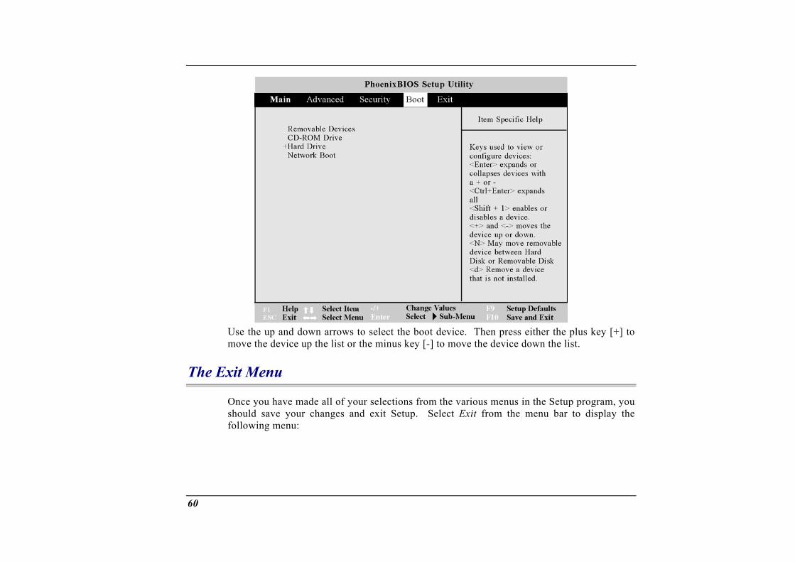
Use the up and down arrows to select the boot device. Then press either the plus key [+] to
ce up the list or the minus key [-] to move the device down the list.
The Exit Menu
move the devi
Once you have made all of your selections from the various menus in the Setup program, you d exit Setup. Select Exit from the menu bar to display the should save your changes an
following menu:
60
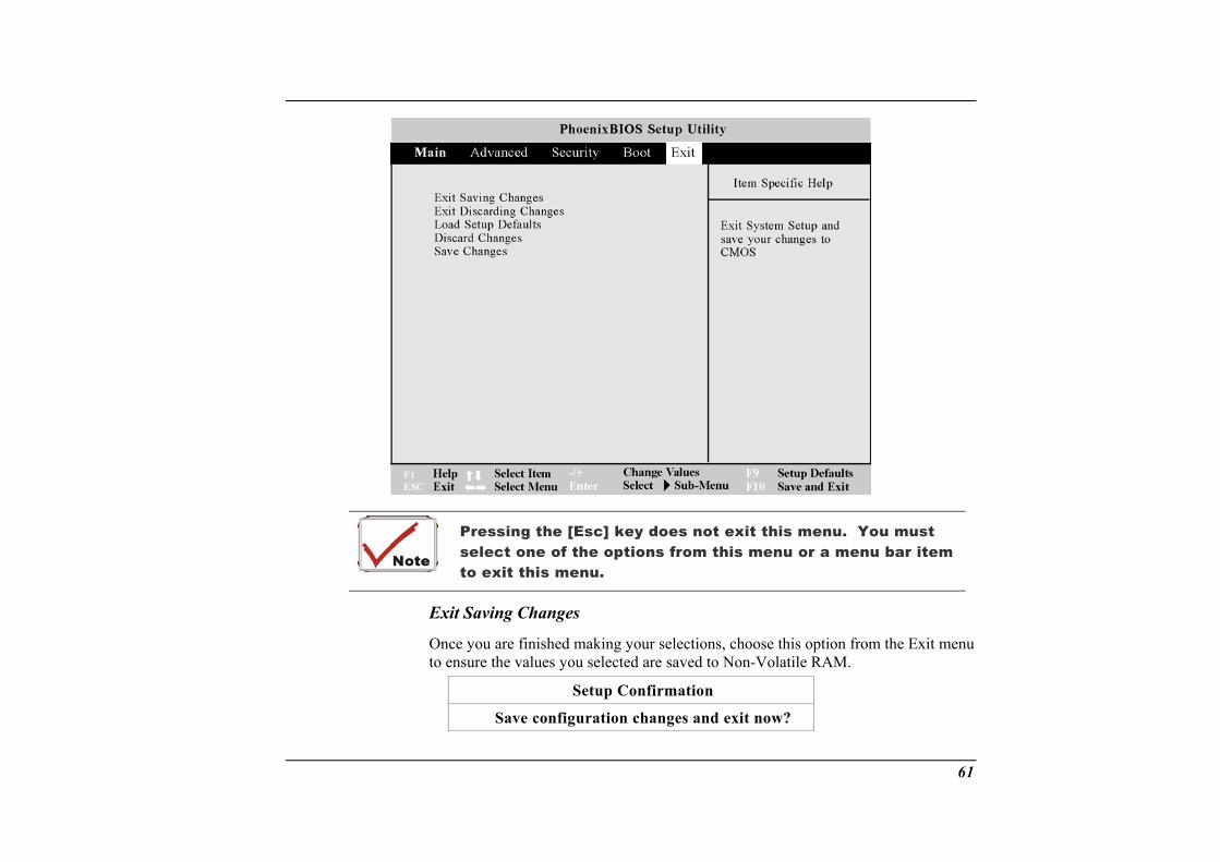
must select one of the options from this menu or a menu bar item to exit this menu.
Pressing the [Esc] key does not exit this menu. You
Exit Saving Changes
Once you are finished making your selections, choose this option from the Exit menu to ensure the values you selected are saved to Non-Volatile RAM.
Setup Confirmation
Save configuration changes and exit now?
61
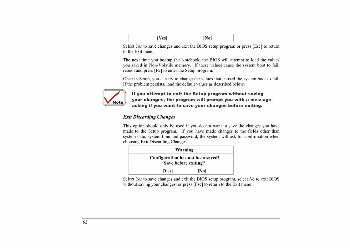
[Yes] [No]
Select Yes to save changes and exit the BIOS setup program or press to the Exit menu.
The next time you bootup the Notebook, the BIOS will attempt to load tyou saved in Non-Volatile memory. If these values cause the systemreboot and press [F2] to enter the Setup program.
Once in Setup, you can try to change the values that caused the systemIf the problem persists, load the default values as described below.
[Esc] to return
he values boot to fail,
boot to fail.
If you attempt to exit the Setup program without sayour changes, the program will prompt you with a message asking if you want to save your changes before exi
Exit Discarding Changes
This option should only be used if you do not want to save the changes you made to the Setup program. If you have made changes to the fields otsystem date, system time and password, the system will ask for confirmchoosing Exit Discarding Changes.
ving
ting.
have her than
ation when
Warning
Configuration has not been saved! Save before exiting?
[Yes] [No]
Select Yes to save changes and exit the BIOS setup program, select No to exit BIOS without saving your changes, or press [Esc] to return to the Exit menu.
62
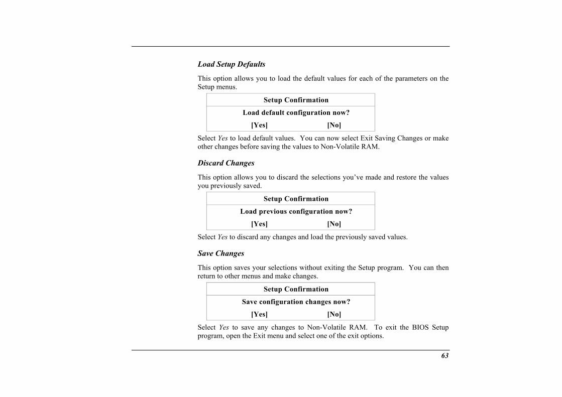
Load Setup Defaults
This option allows you to load the default values for each of the parameters on the Setup menus.
Setup Confirmation
Load default configuration now?
[Yes] [No]
Select Yes to load default values. You can now select Exit Saving Changes or make er changes before saving the values to Non-Volatile RAM.
sc
This opti
Setup Confirmation
oth
Di ard Changes
on allows you to discard the selections you’ve made and restore the values you previously saved.
Load previous configuration now?
[Yes] [No]
Select Yes to discard any changes and load the previously saved values.
Save Change
This option saves your Setup program. You can then return to other menus
s
selections without exiting the and make changes.
Setup Confirmation
Save configuration changes now?
[Yes] [No]
Select Yes to save any changes to Non-Volatile RAM. To exit the BIOS Setup program, open the Exit menu and select one of the exit options.
63
When prompted by BIOS to save your changes before exiting
To exit BIOS SDiscarding Chan
etup without saving your changes, select Exit ges from the Exit menu and press [Enter].
, select [No] and press [Enter].
64

The Software Utilities Disks
6
There are two separate procedures on how to install the .
un”
Driver for WinXP ROM Driver into your DVD-ROM drive.
and Select “Run”.
wing: D:\Driver\AGP\SiSSetup.exe (If D is notte D with the correct drive letter).
driver: AutoRun installation and Manual installation
AutoRun Installation
• Follow the step-by-step procedures on the DVD-ROM to execute the “AutoRapplication by selecting the topic of “Driver Installation”.
• To re-run the “AutoRun” installation, please refer to the procedures on the “Manual Installation” for a more detailed explanation.
Intalling the AGP1. Insert the DVD-
2. Click “Start”
3. Type the follo your DVD-ROM drive, substitu
4. Click on “Setup” to begin the Installation Wizard.
5. Follow the Wizard’s on-screen instructions to complete the installation.
6. Restart the system.
Installing VGA Display Drivers for WinXP This section describes the operation and installation of VGA display software drivers supplied on the Driver Utility DVD-ROM that is shipped with your computer.
1. Insert the DVD-ROM Driver into your DVD-ROM drive.
2. Click “Start” and Select “Run”.
66
3. Type the following: D:\Driver\VGA\ Setup.exe (If D is not your DVD-ROM drive, e D with the correct drive letter).
4. “
5.
m.
Intalling the Audio Driver for WinXP
substitut
Click on
Follo
Setup” to begin the Installation Wizard.
e Wizard’s on-screen instructions to complete the installation. w th
6. Restart the syste
1. e.
3. up.exe (If D is not your DVD-ROM drive, .
Installation Wizard.
5. installation.
6.
Intal
Insert the DVD-ROM Driver into your DVD-ROM driv
2. Click “Start” and Select “Run”.
Type the following: D:\Driver\Audio\Setsubstitute D with the correct drive letter)
4. Click on “Setup” to begin the
Follow the Wizard’s on-screen instructions to complete the
Restart the system.
ling the LAN Driver for WinXP To ins ently installed driver.
1.
2. “Run”.
f D is not your DVD-ROM drive,
5. e installation.
6.
tall the LAN driver you must first remove the curr
Insert the DVD-ROM Driver into your DVD-ROM drive.
Click “Start” and Select
3. Type the following: D:\Driver\LAN\Setup.exe (Isubstitute D with the correct drive letter).
4. Click on “Setup” to begin the Installation Wizard.
Follow the Wizard’s on-screen instructions to complete th
Restart the system.
67
Installing the USB20 Driver for WinXP tall the USB20 driver you must first removTo ins e the currently installed driver.
1. .
2.
3. the following: D:\Driver\USB20\USB20.exe (If D is not your DVD-ROM drive, substitute D with the correct drive letter).
stallation Wizard.
5. e installation.
6.
Insert the DVD-ROM Driver into your DVD-ROM drive
Click “Start” and Select “Run”.
Type
4. Click on “USB20” to begin the In
Follow the Wizard’s on-screen instructions to complete th
Restart the system.
Please note that Window XP Service Pack 1 provides built-in driver for USB 2.0. Do not instdriver CD if you already have Wi
all USB 2.0 driver from ndows XP Service Pack 1
Installing the IR Driver for WinXP To install the IR driver you must first remove
1. Insert the DVD-ROM Driver into your DVD
the currently installed driver.
-ROM drive.
3. our DVD-ROM drive, ve letter).
4.
5. s to complete the installation.
6.
2. Click “Start” and Select “Run”.
Type the following: D:\Driver\IR\Setup.exe (If D is not ysubstitute D with the correct dri
Click on “Setup” to begin the Installation Wizard.
Follow the Wizard’s on-screen instruction
Restart the system.
68

Installing the TouchPad&StickPoint Driver for WinXP To install the touchpad driver you must first remove the currently installed driver.
1.
2.
3. rive letter).
4.
5.
6.
Manua ti
Insert the DVD-ROM Driver into your DVD-ROM drive.
Click “Start” and Select “Run”.
Type the following: D:\Driver\Touchpad&StickPoint\Setup.exe (If D is not your DVD-ROM drive, substitute D with the correct d
Click on “Setup” to begin the Installation Wizard.
Follow the Wizard’s on-screen instructions to complete the installation.
Restart the system.
l Installa on
To install the driver manually, follow the step-by-step procedures described on each n. individual section for a more clear installatio
Installation des CardBus-Treibers für WinXP Gehe allieren:
1. s Symbol "Arbeitsplatz". Klicken Sie auf
2. enschaften" auf das Register "Hardware".
3. .
4. eric " und auf das Register "Treiber".
5. Klicken Sie auf das Register "Treiber aktualisieren" und wählen das Menüelement
n Sie folgendermaßen vor, um den CardBus-Treiber zu inst
Klicken Sie unter "Start" auf da"Systeminformationen anzeigen ".
Klicken Sie im Dialogfenster "Systemeig
Klicken Sie auf die Schaltfläche "Geräte-Manager"
Doppelklicken Sie auf "PCMCIA-Adapter". Doppelklicken Sie auf "GenCardBus Controller
69
"Software von einer Liste oder bestimmten Quelle installieren (für fortgeschrittene Benutzer)". Klicken Sie auf „Weiter".
6. Wählen Sie das Menüelement "Folgende Quelle ebenfalls durchsuchen:" undklicken auf "Durchsuchen". Geben Sie die Position Ihres Treibers an
ion fortzufahren.
Insta /Wireless LAN Driver for WinXP
D:\Driver\Cardbus\ENE1410\WinXP, um mit der Installat
lling the Actiontec Combo1. el" item to open the
2.
3. the click on the "Properties" tab.
ernet Controller Properties" window, click on the "Driver" tab and date Driver" button.
6. Select the "Specify a location" and click the "Browse" button to locate the disk
e installation.
Insta
Click the "My Computer" icon and click on the "Control PanControl Panel.
Double click on the "System" icon. Click the "Device Manager" tab.
Click on the "Other Devices" (denoted by the yellow mark symbol), select"Ethernet Controller" and
4. From the "Ethselect the "Up
5. Click on the "Specify the location of the driver (Advanced)" and again click on the "Next" button.
drive of your DVD-ROM driver.
D:\Driver\MiniPCI\Actiontec\Wireless\WinXP to proceed with th
lling the Accton Combo/Wireless LAN Driver for WinXP 1.
2. er" tab.
3. e
Click the "My Computer" icon and click on the "Control Panel" item to open the Control Panel.
Double click on the "System" icon. Click the "Device Manag
Click on the "Other Devices" (denoted by the yellow mark symbol), select th"Network Controller" and click on the "Properties" tab.
70
4. From the "Network Controller Properties" window, click on the "Driver" tab and select the "Update Driver" button.
5. n the
6. sk drive of your DVD-ROM driver.
Win
Click on the "Specify the location of the driver (Advanced)" and again click o"Next" button.
Select the "Specify a location" and click the "Browse" button to locate the di
D:\Driver\MiniPCI\Accton\wireless to proceed with the installation.
Installing the Actiontec MiniPCI Combo Card Modem Driver for XP
1.
2.
3. D drive, substitute D with the correct drive letter).
4.
5. Wizard’s on-screen instructions to complete the installation. Restart the
Install
Insert the CD-ROM Driver into your CD-ROM/DVD-ROM drive.
Click “Start” and Select “Run”.
Type the following: D:\Driver\MiniPCI\Actiontec\Modem\WinXP\Setup.exe (If is not your CD-ROM/DVD-ROM
Click on “Setup” to begin the Installation Wizard.
Follow the system.
ing the Modem AM303W Driver for WinXP 1. From your screen, click on the “My Computer” icon and use your mouse
touchpad right button to select the “Properties” item. or
2.
3.
4. mbol).
5. em.
Click on the “Hardware” tab from the “System Properties” dialog window.
Double click “Device Manager” tab.
Select the “PCI Modem” in the “Modem” group (denoted by a yellow mark sy
Click the “Driver” tab then click the “Update Driver” it
71
6. Select the “Search for a suitable driver for my device (recommended)” item and click “Next”.
7.
Insta
Click the “Browse” button and specify for the designate location of your CD driver.(D:\Driver\MiniPCI\AM303W\WinXP).
lling the Accton Combo/AC-link MODEM Driver for WinXP 1. In
2. Click “Start” and Select “Run”.
D is your CD-ROM/DVD-ROM drive, substitute D with the correct drive letter).
4.
5. nstructions to complete the installation.
6.
VGA Utilit
sert the CD-ROM Driver into your CD-ROM/DVD-ROM drive.
3. Type the following: D:\Driver\MiniPCI\Accton\Modem\WinXP\Setup.exe (If not
Click on “Setup” to begin the Installation Wizard.
Follow the Wizard`s on-screen i
Restart the system.
ies
After “Disp on. From the “Display Properties” window, select the “Settings” tab and
nd MOBILITY RADEON
you have restarted Windows, open the “Control Panel” and double click on the lay” ic
click on the “Advanced” tab to enter the “Default Monitor a8500 Properties" window.
72
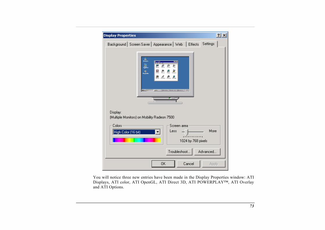
You will notice three new entries have been made in the Display Properties window: ATI Displays, ATI color, ATI OpenGL, ATI Direct 3D, ATI POWERPLAY™, ATI Overlay and ATI Options.
73
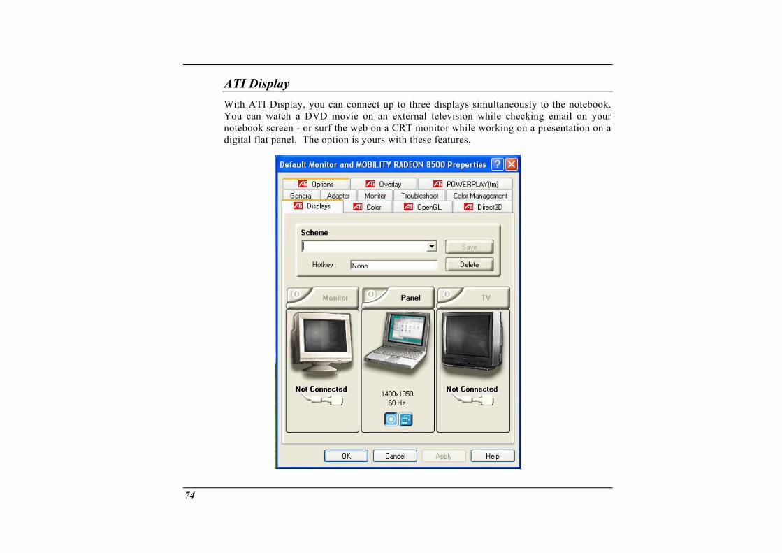
ATI Display With ATI Display, you can connect up to three displays simultaneously to the notebook
watch a DVD movie on an external television while checking email on yscreen - or surf the web on a CRT monitor while working on a presentation on
anel. The option is yours with these features.
. You can our notebook a digital flat p
74
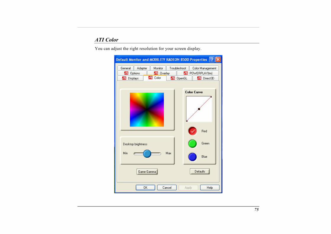
ATI Color You can adjust the right resolution for your screen display.
75
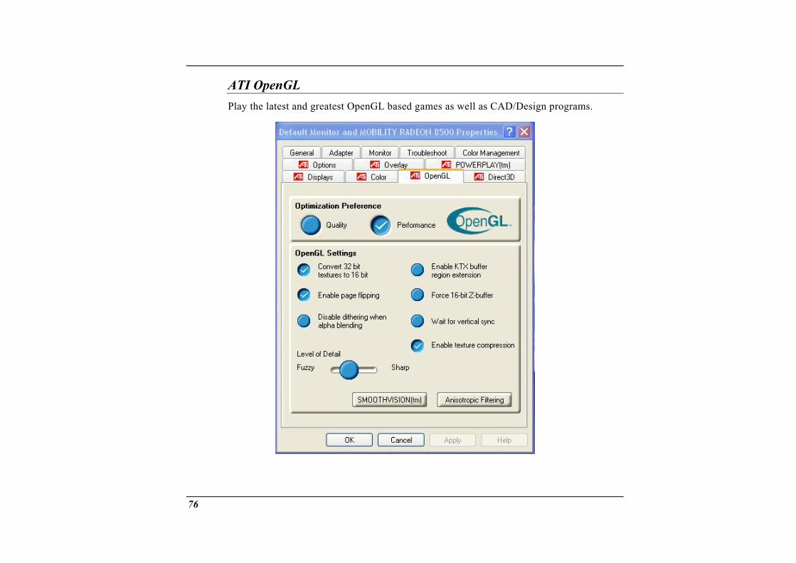
ATI OpenGL Play the latest and greatest OpenGL based games as well as CAD/Design programs.
76
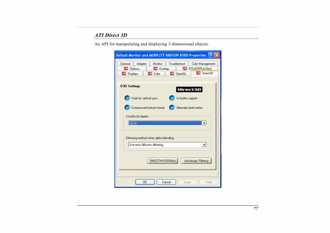
ATI Direct 3D An API for manipulating and displaying 3-dimensional objects.
77
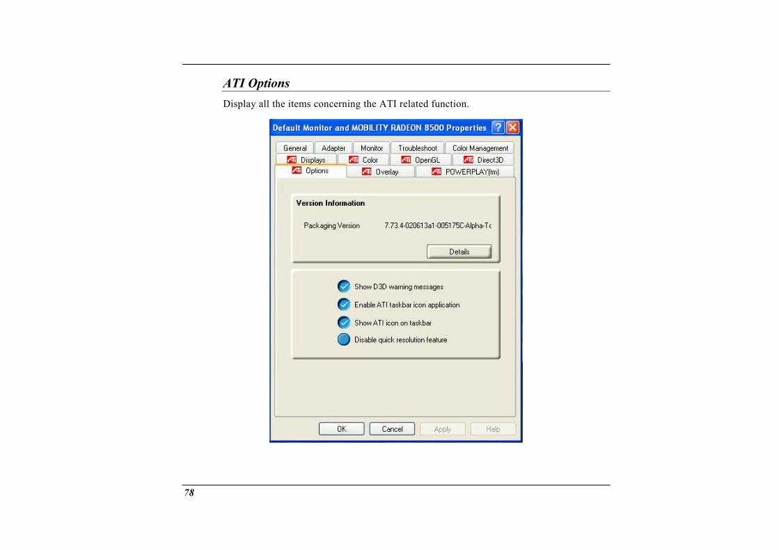
ATI Options Display all the items concerning the ATI related function.
78
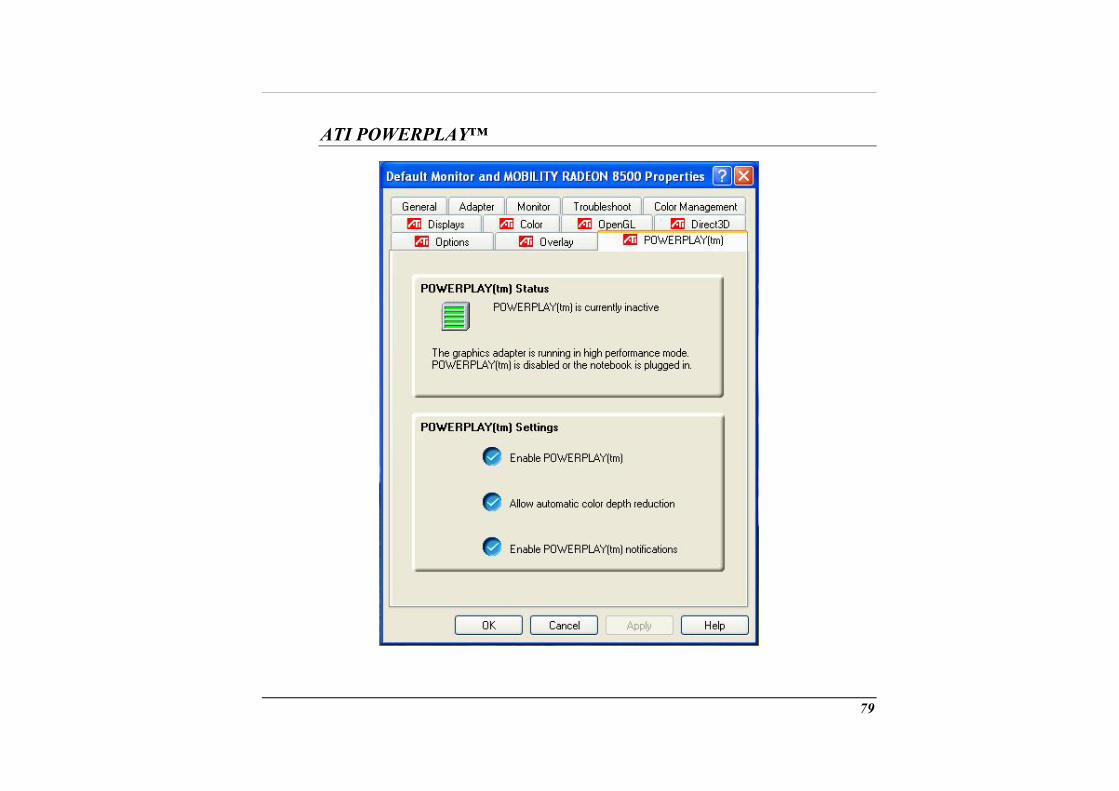
ATI POWERPLAY™
79
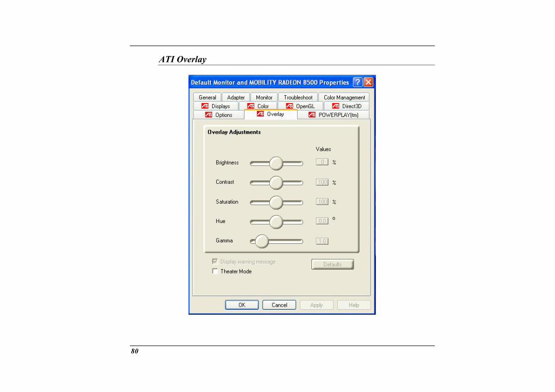
ATI Overlay
80

Troubleshooting
7
81
This chapter describes locating and solving problems that you may encounter while using your computer.
Locating a Problem
Problems with your computer can be caused by something as minor as an unplugged chapter is solutionsorrect the
power cord – or as major as a damaged hard disk. The information in this designed to help you find and solve minor problems. If you try all the suggested and you still have a problem, make a list of what steps you have taken to c problem and contact your dealer.
Successful troubleshooting is the result of careful observation, deductive reasoning, and an organized approach to solving the problem.
The problem categories: hardware problems and divided into electrical and mechani oblem if the screen is dark, the co message during the Power-On Self Test (POST).
Software errors can occur at several levels. The ROM BIOS and the operating system can give you a large number of error messages. On top of this, each application software package has its own set of error messages. It is important to determine whether the software error message you are getting is from the application or the operating system. Once you know this, you can look in the respective manual for a solution to the problem.
Checking Cables and Connections
s that you will encounter can be divided into two basic software problems. Hardware problems can be further
cal problems. You will know you have a hardware prmputer cannot read the disk drives, or you get an error
Start by performing a careful visual inspection of the exterior of the computer. If no LEDs are illuminated, make sure that your computer and its peripherals are getting power and communicating with each other properly.
To check the power cables, and connections:
1. If you have been using battery power, connect the Notebook to an external power
82

source and make sure that the battery has a charge.
2. If you are using the Notebook with the AC adapter, check the power outlet, the power cord, and any power switches that may affect your computer.
e wall outlet or power strip with an item that you know is functioning properly. A lamp or radio is a convenient item for checking the power. You may
evices, look for loose or disconnected
• Check th
also need to check the fuses and breakers in your electric box. • If the outlet is controlled by a wall switch, make sure that the switch is on. • If the outlet is controlled by a dimmer switch, use a different outlet. • If your computer is plugged into a power strip with an On/Off switch, make sure
the switch is on. 3. With the computer’s power switched off, check all cable connections. If the
computer is connected to any peripheral dcables. If the computer is too close to a wall, a cable connection may be loose or the cables may be crimped.
Do not substitute cables for different devices (other than the manufacturer recommended cables) even if they look
exactly alike. The wiring inside the cable may be different.
4. When you are certain that you have power available and all connections are good, turn the computer on again. If the computer still does not start, you may have a hardware problem.
The Power-On Self Test
The Power-On Self Test (POST) runs every time you turn on or reset the Notebook. The POST checks memory, the main system board, the display, the keyboard, the disk drives, and other installed options.
83
A few seconds after you turn on your computer, a copyy screen. A memory test message appears next; as
right message appears on your displa the test continues, memory size increa on the screen
Two cl si• e
s. An
status). These non-critical malfunctions are those that cause tical
In gen lts and g f failure is detected in an area other than the system board th on the screen te est all e un diagno gr
If you n, emits
General Ha ems
ses until all installed memory is tested. Normally, the only test routine visiblewill be the memory test.
as fications of malfunctions can be detected during the POST: Error messages that indicate a failure with either the hardware, the software, or thBasic Input/Output System critical malfunctions (BIOS). These prevent thecomputer from operating at all or could cause incorrect and apparent resultexample of a critical error is microprocessor malfunction.
• Messages that furnish important information on the power-on and boot processes (such as memoryincorrect results that may not be readily apparent. An example of a non-crierror would be a memory chip failure.
eral, if the POST detects a system board failure (a critical error), the computer haenerates a series of beeps. I(such as
andareas of th
stic pr
e display, keyboard, or an adapter card) an error message is displayedsting is stopped. It is important to remember that the POST does not t computer, only those that allow it to be operational enough to rams. o
r system does not successfully complete the POST, but displays a blank screea series of beeps, or displays an error code, consult your dealer.
rdware Probl
A few common hardware problems and suggested solutions are presented in the table
Solution: Please discharged to less than 95% of its capacity then recharge the battery.
below:
Problem: The capacity of the battery is between 95 to 99% but can not fully charged.
84
Problem: Failure in the installation of the Audio driver.
Solution: Be sure to first remove the current audio device from your system. Please follow the instruction on the installation of audio driver.
Problem: The display screen is dark
Sol iocontrols
Proble
Sol iooptions i ur CMOS b
your drive. Contact technical support for assistance.
nd the scope of this manual. Contact technical support.
Solution: Reboot the computer and run the BIOS system setup. Confirm the Setup parameters.support for
Problem:
ut n: Make sure that the computer is not in Suspend mode. Check the Brightness for the screen. If the controls are turned too far down, the screen will be dark.
m: An incorrect date and time are displayed.
ut n: Correct the date and time using the DOS DATE and TIME commands or the n the Setup Utility. If the date and time become incorrect after a short time, yoattery may be depleted. Contact your dealer to change the battery.
Problem: The message: “Invalid system disk, Replace the disk, and then press any key” appears during boot.
Solution: Check and make sure that you do not have a non-bootable floppy diskette inserted in your floppy drive. If your USB FDD is empty, you may not have an operating system installed on
Problem: You hear irregular beeps during operation of the Notebook and the system halts.
Solution: The problem is beyo
Problem: An unidentified message is displayed.
If the same message is displayed after booting up again, contact technical assistance.
The system cannot access the DVD-ROM drive.
85
Solution: Check that a CD is properly inserted in the drive for that kind of CD. For example, the sy
. Make sure that you are using the correct program stem cannot read a data CD using an au
Solution: nnection. Ensure that the printer power switch is turned on.
Solution: Consult you
Solution:
Solution:
Problem:
Check the cable connection. • Ch
incom• If p computer to see if it works. If it doesn’t
ight be broken.
dio program.
Problem: You cannot operate the printer.
Check the printer cable coConfirm that the printer is on-line.
Problem: You can’t save data to disk.
Ensure that the disk has been formatted. r operating system manual for information on formatting floppy diskettes.
Problem: The diskette is write-protected.
Eject the diskette, remove the write protection, and try again.
Problem: The diskette if full.
Try using another diskette or free up some space on the diskette. The disk drive is not operating. Contact your dealer for support.
You cannot use the mouse.
• eck the mouse with another application to see if there is a software
patibility problem. ossible, check the mouse with another
operate on a different system, the mouse m
86
Contacting Your Dealer
If you still ha receding sections, the next step is to contact your dealer. the problem is something that requires the computer to b
Be he following information: • Ho d? Your dealer needs to know what peripheral
• Wh
• Wh o solve the problem? If you have overlooked a problem over the phone.
ve a problem after reading the p Your dealer can determine if
e taken to the shop.
fore you call your dealer, however, prepare tw is your computer configure
devices you are using. at messages, if any, are on the screen?
• What software were you running at the time? at have you done already to try t
step, your dealer may be able to solve the
87

88

Upgrading your System
8
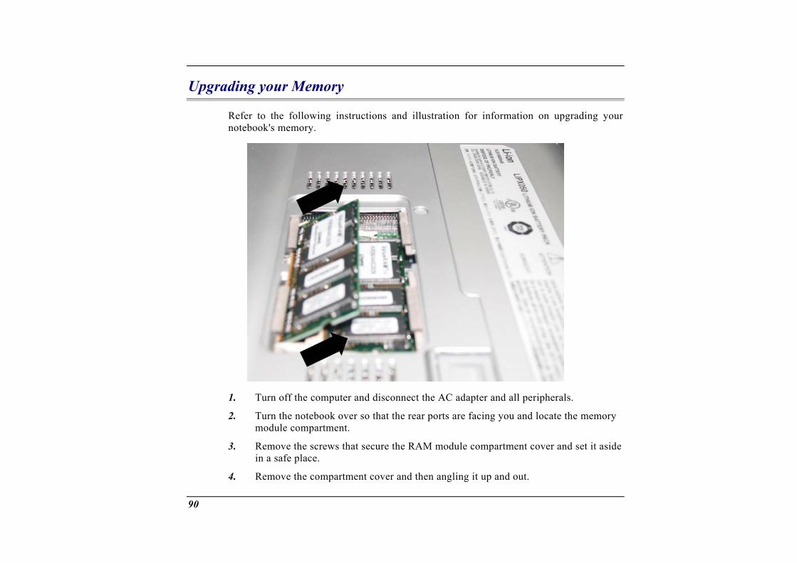
Upgrading your Memory
Refer to the following instructions and illustration for information on upgrading your notebook's memory.
1. Turn off the computer and disconnect the AC adapter and all peripherals.
2. Turn the notebook over so that the rear ports are facing you and locate the memory module compartment.
3. Remove the screws that secure the RAM module compartment cover and set it aside in a safe place.
4. Remove the compartment cover and then angling it up and out.
90

5. If you need to install sides to release the m
a higher capacity module, gently push the edge clips on both odule. Angle the card slightly upward and gently slide it from
its edge connector slot. Store the card in the anti-static bag that contains your new
w memory card, hold the card with its gold edge connector toward s, the edge
be able
7.
8. es of
9. mpartment.
10.
The Easy
module(s).
6. To install the nethe edge connector slot of the compartment. To help you orient the cardconnector has been made with two unequal-length sections. You will onlyto insert the card in one direction.
Insert the edge connector into the slot. The gold edge connector of the card should not be visible when the card is fully inserted.
Press the card downward where you should hear an audible click as the latchthe connector secure the card in place.
Once the module is properly seated, you can replace the cover on this co
Replace and tighten the screw.
to Upgrade HDD Module
ard drive in your notebook computer is made to be easily swapped out for upgradingld back up your hard drive before attempting o change the hard drive.
he files Make sure that before you install a new drive, all tin your system should be backed up.
The h . You shou
To upgrade your Hard Drive Power down the syste1. m completely. Turn the system over with the front of the unit
2. e screws that secure the compartment cover and set them in a safe
facing you.
Remove the threplace.
91
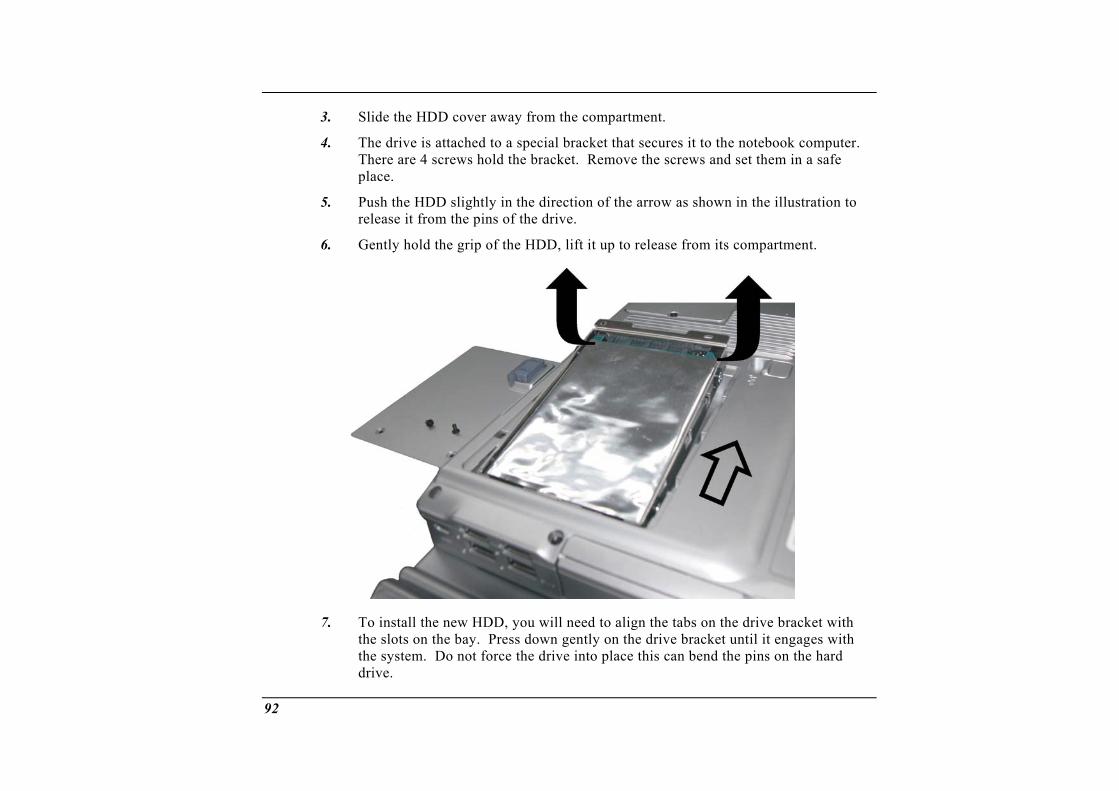
3. Slide the HDD cover away from the compartment.
The drive is attached to a special bracket that secures it to the notebook computer. There are 4 screws hold the bracket. Remove the screws and set them in a safe place.
4.
5.
6.
Push the HDD slightly in the direction of the arrow as shown in the illustration to release it from the pins of the drive.
Gently hold the grip of the HDD, lift it up to release from its compartment.
7. the bay. Press down gently on the drive bracket until it engages with
To install the new HDD, you will need to align the tabs on the drive bracket with the slots on the system. Do not force the drive into place this can bend the pins on the hard drive.
92
8. Slide talign
he compartment cover into place and be sure the screw holes on the cover completely with the screw holes in the case.
9.
CPU Upgr
Secure the cover with the three screws.
ade
To up
1. 2. 3. 4.
5. ving the
6. 7. the screw
grade your CPU, follow the procedures below:
Turn the notebook over so that the rear ports are facing you. Locate for the expansion compartment. Unscrew and remove the cover of the CPU compartment. Remove all the screws attached to the heatsink.
Before removing the screws, there are certain measures to followed in remoheatsink To remove the heatsink, first loosen the screw carefully. After loosening one screw, be certain that the next to be loosen should be on its adjacent side as shown on the illustration.
93
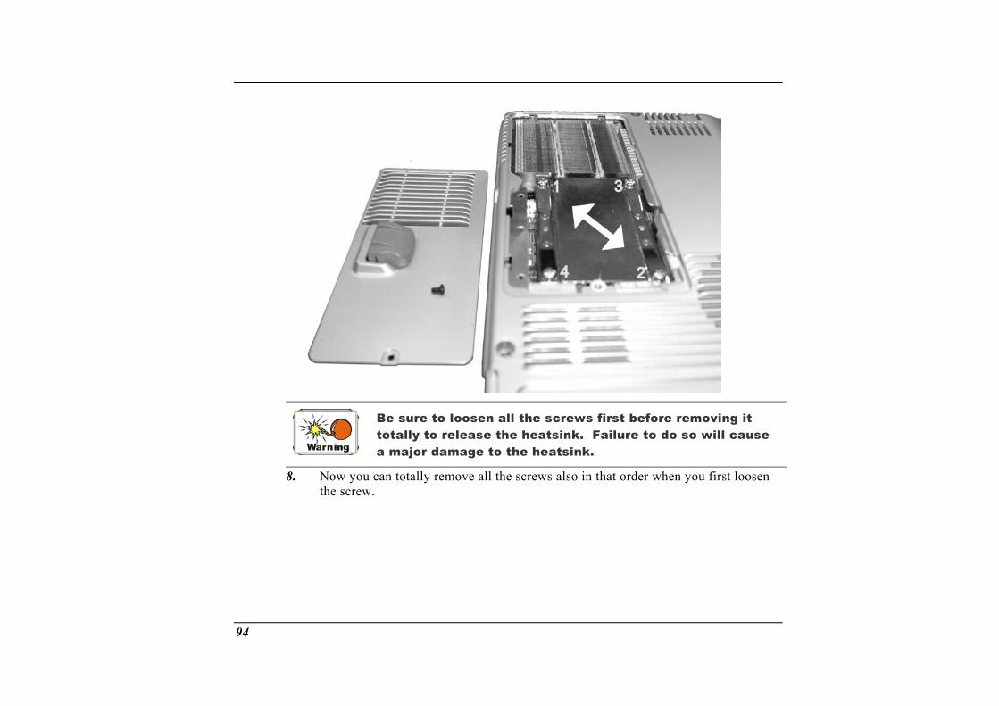
Failure to do so will cause
a major damage to the heatsink.
Be sure to loosen all the screws first before removing it totally to release the heatsink.
8. Now you can totally remove all the screws also in that order when you first loosen the screw.
94
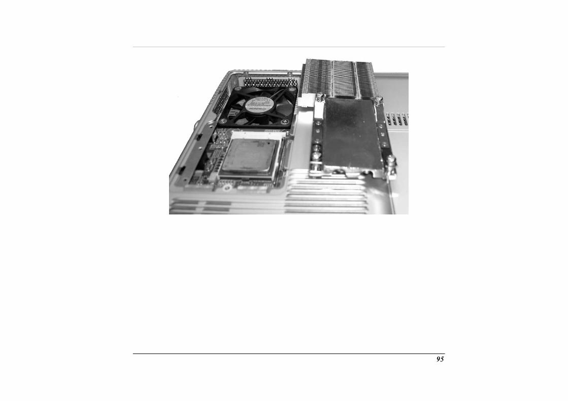
95

96

Specification
A
Detailed Notebook Specifications
General
CPU
• Intel uFCPGA478 P4/Northwood CPU, 512KB L2 cache on die, FSB=533MHz
mory xpansion slots for 200 pin DDR module, up tpport 2.5V DDR 266/333 module
up to 3.2GHz HT
Memory
Main Me• 2 e o 1GB system memory • Su
ROM • 512KB Flash ROM • Boot block protection
Core Logic
• SiS 645DX+962, support Hyper Threading (HT) Function • 4X AGP bus interface • Supports host bus at 533MHz • AGP v2.0 compliant • 3.3V PCI version 2.2 compliance • ACPI v1.0b • USB 2.0 compatible
98
• Expansion 2 slots of 200 pin DDR SDRAM module.
Mass Storage
HDD
• Support enhanced IDE (PIO mode 4) and bus master (Ultra DMA 33/66/100 mode)
• Easily upgradable 2.5" 9.5mm HDD
D-ROM/Combo/DVD Multi Drive; 5.25" 12.7mm height Fast IDE and ATAPI interface DVD-ROM/Combo Drive
PCMCIA Sockets
I, support CardBus
Pointin D
Module Bay
• Supports DV•
• 1 Type I
g evices
• uchPad • four way scrolling feature
Keyboa d
Synaptics ToSupport
r
• US/Europe, DOS/V keyboard for Japan, full size keyboard alike pitch • 300 mm keyboard with key stroke 3.0mm • Twe e f• Inte al ard 101/102 desktop keyboard • 2 sh t-c
Audio
lv unction keys and Windows Function key rn keyboard works a standor ut keys: WWW & eMail
• Dua ull ct Sound Channels • -mode DOS legacy compatibility
l f -duplex DireHardware SoundBlaster Pro for real
99
• 18-bit DC & DAC resolution A
IF out DIF, 5.1 channel support, built-in four stereo speakers
I
• Support SPD• AC97 2.1, SP
/O Ports
• One ara• One -vi• C jack) • • One ide• USB 2.0 port • jack w/ adaptor for 5.1 channel SP/DIP support •
AN • 1394A
Video y
p llel port supported EPP/ECP (25-pin female D-connector) S deo TV out port for TV
input port for External AC adapter (2-pin DOne DC One Type II PCMCIA card socket
v o port for external analog VGA monitor (15-pin female D-connector) x 4
MIC-in, headphoneRJ-11 jack for Fax/Modem
• RJ-45 jack for L
S stem
Display
• 16" SXGA+/UXGA
Elect cari l
AC Adapter
• External universal type AC adapter, 90W or 120W (for 3.0GHz CPU or above)
100
Smart Battery
• 12 x 18650 Li-Ion battery pack @87.02W or 95.46W (for 3.06G CPU) erchangeable
ovable and rechargeable spend mode
e time under Ziff-Davis Inc. BatteryMark 4.0 XGA+UXGA LCD
Dime si
• User int• Rem• Charge modes - 3.5 hours to full charge when system is off or in su• More than 2.5 hours of battery lif
Test with Intel 478 pin Northwood 2.0GHz CPU and 16.1" Sinstalled at 25°C
n ons • Weight: 3.8Kg with 16.1" display panel, battery and DVD-ROM drive installed
Oper in
• Size: 371mm (W) x 286.7mm (D) x 37.8/47.5mm (H)
at g Environment
Temperature
• Operating: 5°C ~ 35°C ge: -20°C ~ 60°C
Humi
• Stora
dity
• Op•
erating: 30% ~ 90% (non-condensing) Non-operating: 10% ~ 90% (non-condensing)
Altitude
• Operating: -200 to 10,000 feet above sea level • Non-operating: -200 to 30,000 feet above sea level.
101
Options • Li-Ion battery pack
dem
•
Accessories
• Factory option: Fax/Modem miniPCI card, 802.11b wireless LAN + mocombo miniPCI card
• Factory option: Audio DJ • Factory option: K/B with StickPoint & dual-pointing touch pad • Memory Extension card
Module bay: DVD-ROM/Combo (DVD-ROM+CD-RW)/DVD Multi Drive
• User's manual (option) • Driver CD title • AC adapter • Power cord
Software Specifications
System Software
• System OS BIOS: Phoenix BIed Operating Systems
Optional Windows XP or above version Standard Software Driver
Audio driver 1394 driver
• Support
• s VGA driver
TouchPad&StickPoint driver IR driver (optional)
102

Modem driver LAN driver Wireless LAN driver CardBus driver USB20 driver
103