notified in army orders for february, 1936 crown copyright ... · pdf filetext book of...
TRANSCRIPT

26 Manuals
1543
Notified in Army Orders for February, 1936
Crown Copyright Reserved
FOR OFFICIAL USE ONLY
This Document is the Property ofH.B.M. Government
NOTE
The information given in this document isnot to be communicated, either directly orindirectly, to the Press or to any person notholding an official position in His Majesty'sService.
TEXT BOOKOF
AMMUNITION
1936
LONDON
PUBLISHED BY HIS MAJESTY'S STATIONERY OFFICE
1936
Talpo.it
Talpo.it
Talpo.it

4
TABLE OF CONTENTS-continuedPAGE
CHAPTER .--continued.§1.39 Metals ... 45
§1.40 Textile goods ••• ... 47
§1.41 Paper goods ... 50
CHAPTER II.-CARTRIDGES.
§2 .01 Definitions 52
§2.02 The comparative advantages of the B.L.. and Q.F. cartridgesystems from the point of view of ammunition 53
§2.03 Determination of charge weight 54
§2.04 Adjusted charges 54
§2.05 Ballistic grouping of Lots 54
§2.06 Propellants in use ... 55
§2.07 Arrangement of the propellant 56
§2.08 Composite charges ... 56
§2.09 N.C.T. charges 57
§2.10 Flash-reducing charges 58
§2.11 Super-charges ... 59
§2.12 Charges for the prevention of coppering 59
§2.13 General functions of igniters ... 59
§2.14 Standardized igniters 60
§2.15 Auxiliary igniters 61
§2.16 Igniter covers 61
§2.17 Q.F. igniters ... 61
§2.18 B.L. cartridges. Construction 62
§2.19 1, Materials ... 63
§2.20 Diameter and length 64
§2.21 Cartridges for B.L. guns in the field 64
§2.22 Cartridges for B.L. guns in the coast defence 64
§2.23 Cartridges for star shell 64
§2.24 Drill cartridges ... ••• 64
§2.25 Design of B.L. howitzer cartridges ... 64
§2.26 Arrangement of howitzer cartridges ... 66
§2.27 Markings on B.L. cartridges ... 67
§2.28 Q.F. cartridges. Introduction 69
§2.29 Construction 69
§2.30 Quality of materials 70
§2.3 1 The manufacture of brass cartridge cases 70
§2.32 Testing of cases... ••• 72
§2.33 Cleaning of cases 72
§2.34 Life of a Q.F. case ••• 72
§2.35 Typical Q.F. cartridges ••• 73
§2.36 Markings on Q.F. cartridge cases 74
§2.37 Packing of cartridges ... 79
Talpo.it
Talpo.it
Talpo.it

5
TABLE OF CONTENTS-continued
CHAPTER III.-TUBES.PAGE
§3.01 Definition 81
§3.02 Tubes general ... 81
§3.03 Initial ignition of the charge 81
§3.04 Packing of tubes 82
§3.05 Nature of tubes... ... 82
§3.06 Tube friction Mark IV 82
§3.07 Tube percussion " T " ••• 83
§3.08 Tube percussion S.A. cartridge, Mark II 84
§3.09 Tubes, vent percussion and electric ... 84
§3.10 Tube vent percussion -4-inch, Mark VIII 85
§3.11 Tubes, vent electric ... ... 86
§3.12 Tube vent electric -4-inch, Mark X ... 86
§3.13 Tube vent electric -5-inch, Mark VIII 87
§3.14 Drill tubes ... 87
§3.15 Markings of tubes ..• 88
§3.16 Defects in tubes ••• 88
§3.17 Employment of tubes 89
CHAPTER IV.-PRIMERS.
§4.01 Definition 91
§4.02 Electric primers 91
§4.03 Percussion primers ••• 91
41-4404 Markings on primers ... 92
§4.05 Primer, percussion Q.F. cartridge, No. 1, Mark II 92§4.06 Primers, percussion Q.F. cartridge, No. 2 ... 93
• §4.07 Primer, percussion Q.F. cartridge, No. 11, Mark I 93
CHAPTER V.-PROJECTILES.
§5.01 Types of projectiles ... 95
§5.02 Design of Projectiles-Introduction 95§5.03 Forces of projection ... 96§5.04 Ballistic qualities in flight 99§5.05 Weight 100§5.06 Shape of projectile-external 100§5.07 Steadiness during flight 103§5.08 Length of projectile ... ••• 104§5.09 Diameter of projectile ... 106§5.10 Driving bands 106§5.11 Shape of projectile-internal ... 114§5.12 Capped shell ... 115§5.13 Shell for use in guns and howitzers 116§5.14 Manufacture of shell ... 116§5.15 Practice shot ... ••• 118
Talpo.it
Talpo.it
Talpo.it

6
TABLE OF CONTENTS-continued
CHAPTER V.-continued.
§5.16 Proof shot 118
§5.17 Paper shot 118A
§5.18 etie shot 118
§5.19 Common pointed (C.P.) and common pointed capped(C.P.C.) shell ... -•• ••• 118
§5.20 Armour-piercing (A. P.) and armour-piercing capped(A.P.C.) shell ... 120
§5.21 Semi-armour-piercing (S.A.P. and S.A.P.C.) shell H.E. 122
§5.22 High explosive (H.E.) shell 122
§5.23 Filling of H.E. shell ... 123
§5.24 Development of the modern exploder system 125
§5.25 Efficiency of H.E. shell 130
§5.26 Smoke shell ... 132
§5.27 Shrapnel shell ... 133
§5.28 Star shell 135
§5.29 Practice projectiles es 136
§5.30 Tracer shell 137
§5.31 Drill shell 137
§5.32 Mortar ammunition 137
§5.33 3-inch mortar bomb 10-1b. 138
§5.34 Insertion of plugs and fuzes 138
§5.35 Causes of blinds and prematures 139
§5.36 Markings on projectiles 140
§5.37 Weight markings on projectiles 145
CHAPTER VI.-FUZES AND GAINES.
§6.01 General remarks 147
§6.02 Metals used in manufacture of fuzes 147
§6.03 Safety arrangements ... 150
§6.04 Dynamical factors governing design 151
§6.05 Detonators for fuzes and gaines 158
§6.06 Gauge of fuzes ... 159
§6.07 Nomenclature of fuzes 159
§6.08 Blinds and prematures 160
§6.09 Markings of fuzes 162
§6.10 Percussion fuzes-direct action (D.A.) fuzes 163
§6.11 Fuze, percussion, D.A., No. 44, Mark X ... 165
§6.12 Fuze, percussion, D.A., No. 106E, Mark VIIIZ 166
§6.13 Fuze, percussion, D.A., No. 117, Mark IIIZ 169
§6.14 Fuze, percussion-direct action impact (D.A.I.), No. 45,Mark IXZ 170
§6.15 Graze action fuzes 171
§6.16 Graze, percussion, nose fuzes ... 172
PAGE
Talpo.it
Talpo.it
Talpo.it

TABLE OF CONTENTS-continuedPAGE
CHAPTER VI.-continued.
§6.17 Fuze, percussion, No. 101E, Mark JIM, and gaine, No. .2.., 173Mark IV, with delay ...
§6.18 Graze, base, percussion fuzes ... 175
§6.19 Fuze, percussion, base, Hotchkiss, Mark X 176
§6.20 Fuze, percussion, base, large No. 16, Mark IV 176
§6.21 New base fuzes ... ... ... ... 178
§6.22 Time, and time and percussion fuzes-Introduction 178
§6.23 Influences affecting rate of burning ... 180
§6.24 Burning or composition fuze mechanisms 183
§6.25 Fuze, time and percussion, No. 80, Mark X1 187
§6.26 Fuze, time and percussion, No. 88, Mark VI 189
§6.26 (a) Fuze, time and percussion, No. 220, Mark I 190
§6.27 Fuze, time, No. 199, Mark HI 190
§6.28 Mechanical fuzes ... 191
§6.29 Mechanical time fuzes ... 192
§6.30 Fuze, time, No. 203, Mark I ... 192
§6.31 Fuze, time, No. 200 ... 195
§6.32 Mechanical distance fuzes ... 196
§6.33 Preservation of fuzes-effect of climate 197
§6.34 Fuze cylinders ... ... ... 197
§6.35 Waterproofing and sealing of fuzes 197
16.36 Fuze covers 198
§6.37 Mortar fuzes ... ... 198
§6.38 Fuze, percussion, D.A., No. 138, Mark I ... 199
§6.39 Fuzes, percussion, D.A., Nos. 139 and 139P 200
§6.40 Rust-proofing ... ... ... 200
§6.41 Table of fuzes for land service 201
CHAPTER VII.-IMPLEMENTS FOR SETTING TIME FUZES.
§7.01 Introduction ... 209
§7.02 Theory of the corrector ... 209
§7.03 Height-fuze indicators for high-angle fire 213
§7.04 Fuze-setting instruments 213
§7.05 Fuze keys ••• 213
§7.06 Fuze-setting machines 214
CHAPTER VIII.-SMALL ARM AMMUNITION.
§8.01 Introduction ... 215
§8.02 -303-inch Service ball cartridge 217
§8.03 -303-inch armour-piercing cartridge 218
§8.04 -303-inch tracer cartridge ... ... 218
§8.04 (a) •303-inch observing cartridge ... 219
§8.05 Special ammunition for the Royal Air Force 220
Talpo.it
Talpo.it
Talpo.it

8
TABLE OF CONTENTS continuedPAGE
CHAPTER VIII.-continued.§8.06 -303-inch blank cartridge 221§8.07 -303-inch drill ammunition ... •.• 222
§8.08 -303-inch dummy ammunition 222§8.09 Packing of •303-inch ammunition 223§8.10 Revolver and pistol ammunition 224§8.11 Cartridge, S.A., ball, revolver, -455-inch, Mark II ... 225§8.12 Cartridge, S.A., ball, pistol, self-loading, -455-inch, Mark I 225
§8.13 Cartridge, S.A., blank, revolver, •455-inch, L Mark IIT 225
§8.14 Cartridge, S.A., drill, revolver, -455-inch, D Mark I 225
§8.15 Cartridge, S.A., ball, revolver, •380-inch, Mark I 226
§8.16 Cartridge, S.A., ball, •5-inch, Mark IIZ 228
§8.17 Miniature rifle ammunition ... 229
§8.17 (a) Note regarding packing and labelling of S.A.A. 231§8.18 Inspection and proof of small-arm ammunition 231
§8.19 Defects in small arm ammunition ... 232
CHAPTER IX.-1-INCH AIMING RIFLE AMMUNITION.
§9.01 Introduction ... 233
CHAPTER X.-GRENADES.
§ 10.01 Introduction ... 235§10.02 Hand grenades .. 235§10.03 Rifle grenades ... 236§ 10.04 Grenade, -303-inch rifle, No. 36M, Mark I 237§ 10.05 Signal grenades 239§10.06 Signal grenades, 22-inch 240§ 10.07 Grenade No. 54, Mark I 240
§ 10.08 Grenade No. 63, smoke, 2 .5-inch, Mark I 243
§ 10.09 Rifle grenade cartridges 244
§10.10 Discharger, grenade, rifle, 2-inch, No. 1, Mark I 245
§ 10.11 Markings on grenades (other than signal) ... 246
CHAPTER XI.-DEMOLITION AND BLASTING EXPLOSIVES, AND STORESCONNECTED THEREWITH.
§11.01 Introduction 248
§11.02 Guncotton 248
§11.03 Ammonal 250§11.04 Nitroglycerine explosives 250§11.05 Methods of firing... ... 251
§11.06 Fuze, safety, No. 16, Mark I ... 252
§ 11.07 Quick-match, 4 thread and 6 thread 252
§11.08 Fuze, instantaneous, Mark IV 252
§11.09 Fuze, instantaneous, detonating (Cordeau Detonant) 252
Talpo.it
Talpo.it
Talpo.it

9
TABLE OF CONTENTS—continued
CHAPTER XI.—continued.PAGE
§11.10 Detonator, No. 8, Mark VII ... ... 253
§11.11 Detonator, No. 27, Mark I ... ... 253
§11.12 Detonator, electric, No. 9, Mark IV ... ... 253
§11.13 Fuze, electric, No. 14, Mark IV ... ... 254
CHAPTER XII.—PYROTECHNIC STORES.
§ 12.01 Introduction •••
§12.02 Rockets ...
255,
255
§12.03 Rockets, signal ... 256
§12.04 Rocket, light, parachute, 1-lb., Mark II 256
§ 12.05 Lights ... 257
§12.06 Port-fires 257
§12.07 Slow-match, Mark I 258
§12.08 Signal cartridges 258
§ 12.09 Illuminating cartridges 258
§ 12.10 Ground flares ... 258
§12.11 Smoke producers 259
§12.12 Signal vertical light ray 260
§12.13 Thunderflash, Mark I ... 260
TABLES
Table 1.07 Composition and explosion constants of differentpropellants 19
Table 1.08 Properties of high explosives 21Table 1.30 Initiating agents ... 38Table 3.17 Employment of tubes ... 89Table 5.24 Future standard methods of filling for the land service 129
Table 6.41 Table of fuzes for land service ... 201
LIST OF FIGURESCHAPTER I.
Fig. 1.14.—Pictorial representations of cordite 26
Fig. 1.19.—Pictorial representations of cordite S.C. 28
CHAPTER II.
Fig. 2.08.—Cartridge B.L. 12-inch howitzer ... ••• 57Fig. 2.14.—Igniters, old and standardized types 60Fig. 2.17.—Q.F. metal igniter with Mark VI adapter... 62
Fig. 2.18.—Cartridge B.L. 6-inch gun ... 64Fig. 2.20.—Cartridge B.L. 6-inch gun dumb-bell shape ••• 64
Talpo.it
Talpo.it
Talpo.it

10
LIST OF FIGURES—continuedPAGE
CHAPTER II .—continued.
Fig. 2.22.—Cartridge B.L. 9 .2-inch gun, cordite ... 64
Fig. 2.25.—Cartridge B.L. 9 .2-inch howitzer ... ... 64
F
Fig. 2.35(a).—Cartridge Q.F. 4 .7-inch Marks III-IV* guns
-. 73Fig. 2.35 (b).—Cartridges Q.F. fixed ammunition. Typical for fullcharge ... ... ... ... 74
Fig. 2.35 (c).—Cartridge for Q.F. 3 .7-inch howitzer 73
Fig. 2.36(a).—Typical sketch of stampings on base, repaired cases 76
Fig. 2.36(b).—Stencillings on the side and base of Q.F. cartridges,separate ammunition (typical)... ... ... ... 76
CHAPTER III. •
Fig. 3.07.—Tube, Percussion " T " Mark I ... 83
Fig. 3.08.—Tube, percussion S.A. cartridge, Mark II ... 84
Fig. 3.10.—Tube, vent, percussion -4-inch, Mark VIII 86
Fig. 3.12.—Tube, vent, electric, -4-inch, Mark X ... 87
CHAPTER IV.
Fig. 4.05.—Primer, percussion, Q.F. cartridges, No. 1, Mark II 92
Fig. 4.05(a).—Primer, percussion, 6 and 3 prs.. blank, Mark III 92
Fig. 4.06.—Primer, percussion, Q.F. cartridges No. 2, Marks III,IV and VII... 93
Fig. 4.07.—Primer, Percussion, Q.F. cartridges, No. 11, Mark I 94
CHAPTER V. PROJECTILES.
Fig. 5.06 (a) .—Shape of head 102
Fig. 5.08 (a) .-6-inch, C.P.B.C. 105
Fig. 5.08 (b).-6-inch, A.P.C. 105
Fig. 5.10(a).—Method of attachment of driving band (ribs triangularin section) 108
Fig. 5.10(b).—Method of attachment of driving band (knurled groove) 108
Fig. 5.10(c).—Types of driving bands for guns 112
Fig. 5.10(d).—Types of driving bands for howitzers ... 113
Fig. 5.10(e).—Economy driving bands-6-inch 26-cwt. howitzer and60-pr. gun • • • • 113
Fig. 5.10(f).—Double driving bands 113
Fig. 5.10 (g).—Augmenting strip 114
Fig. 5.11.—Shell B.L. with cap, 9 . 2-inch gun, Mark XIIB 115
Fig. 5.17.—Paper shot ... . 119
Fig. 5.19(a).---Method of filling shell, Q.F. common pointed 12-pr.non-burster bag type ... 118
Fig. 5.19(b).—Common pointed shell with cap filled powder 119
Fig. 5.19(c).—Method of filling shell, B.L. (C.P.) typical for 6-inchguns and 6-inch howitzers and above field service ••• 120
Talpo.it
Talpo.it
Talpo.it

1 1
LIST OF FIGURES—continuedPA GE
CHAPTER V.—continued.
Fig. 5.20 (a).—Armour-piercing shell filled powder ... 121
Fig. 5.20(b).—Armour-piercing shell with cap filled H.E. 122
Fig. 5.20(c).—Armour-piercing shell with cap filled H.E. trotyl bees-wax... ••- 121
Fig. 5.24(a).—Method of filling shell, B.L. or Q.F., H.E. for coastdefence, 12-pr. and above ... •-• 124
Fig. 5.24(b).—Method of filling, shell B.L.H.E., 6-inch gun, MarkXXVI/XXB., coast defence ... ... 126
Fig. 5.24 (c). —Shell, B.L. or Q.F., H.E. (typical) for separate loadingammunition, poured fillings ... ••• ... 127
Fig. 5.24(d).—Method of filling—H.E. shell, 3 .7-inch to 9.2-inch,amatol 80/20, hot mixed ... 128
Fig. 5.24(e).—Method of filling, 13- and 18-pr. (typical) ... 128
Fig. 5.24(f).—Method of filling shell, Q.F.H.E., 3-inch, 20-cwt. 16-1b.Mark IIB ••• 130
Fig. 5.24 (g).—Method of filling shell, B.L.H.E. streamline, 6-inchhowitzer, amatol 80/20, hot mixed . 130
Fig. 5.26.—Smoke shell (typical) ••• 132
Fig. 5.27.—Method of filling, shrapnel shell ... 134
Fig. 5.28.—Method of filling, shell, B.L. or Q.F. star (typical) 136
vFig. 5.33 (a) .—Bomb, M.L.H.E., 3-inch mortar, 10-1b., Mark II 138
Fig. 5.33(b).—Cartridges, M.L. 3-inch mortar, augmenting 100 grainsN.C.(Y.) and 95 grs. Ballistite 138
Fig. 5.36.—Distinguishing markings for gun and howitzer projectiles 146
`PTER VI.—FuzEs.
'Fig. 6.11.—Fuze, percussion, D.A. with cap, No. 44, Mark XZ 166Fig. 6.12.—Fuze, percussion, D.A., No. 106E, Mark VIIIZ 168Fig. 6.13.—Fuze, percussion, D.A., No. 117, Mark IIIZ 169Fig. 6.14.—Fuze, percussion, D.A. Impact, No. 45, Mark IXZ 1 70Fig. 6.16.—Game No. 9, Marks II and IIZ 173Fig. 6.17.—Fuze, percussion, No. 101E, Mark TIM (with Gaine
No. 2, Mark IV with delay) ... 174Fig. 6.19.—Fuze, percussion, base, Hotchkiss, Mark X ... 176Fig. 6.20.—Fuze, percussion, base large, bronze, No. 16, Mark IV 178Fig. 6.25(a).—Fuze, time and percussion, No. 80, Mark XI ... 188Fig. 6.25 (b) .—Fuze, time, No. 80/44, Mark V ... 188Fig. 6.26.—Fuze, time and percussion, No. 88, Mark VI 189Fig. 6.26(a).—Fuze, Time and percussion, No. 220, Mark I 190Fig. 6.27.—Fuze, time, No. 199, Mark III 191Fig. 6.30(a).—Fuze, time, No. 203, Mark I 193Fig. 6.30(b).—Fuze, time, No. 203, Mark I 194Fig. 6.38.—Fuze, percussion, D.A., No. 138, Mark I ... 199Fig. 6.39.—Fuzes, percussion D.A., Nos. 139 and 139 P. 200
Talpo.it
Talpo.it
Talpo.it

1„
12
LIST OF FIGURES—continuedPAGE
CHAPTER VII.-IMPLEMENTS FOR SETTING TIME FUZES.
Fig. 7.02(a).—Indicator fuze, No. 10, Mark I ... ... 211
Fig. 7.02 (b) .—Trajectory curve ... ... 212
Fig. 7.02(c).—Trajectory curve ... . 212
CHAPTER VIII.-SMALL ARM AMMUNITION.
Fig. 8.02.—Cartridge, S.A., ball, •303-inch, Mark VII 217
Fig. 8.03.—Cartridge, S.A. armour-piercing, •303-inch, W. Mark I 218
Fig. 8.04.—Cartridge, S.A. tracer, •303-inch, G. Mark I 218
Fig. 8.06.—Cartridge, S.A. blank, •303-inch, L. Mark V 221
Fig. 8.07.—Cartridge, S.A. drill, •303-inch, D. Mark VI ... 222
Fig. 8.11.—Cartridge, S.A. ball, revolver, •455-inch, Mark II 226
Fig. 8.12.—Cartridge, S.A. ball, pistol, self-loading, -455-inch, Mark I 226
Fig. 8.13.—Cartridge, S.A. blank, revolver, -455-inch, L. Mark IIT 226
Fig. 8.15(a).—Cartridge, S.A. ball, revolver, •380-inch, Mark I ... 226Fig. 8.15(b).—Cartridge, S.A. blank, revolver, •380-inch, L. Mark IT 226
Fig. 8.16.—Cartridge, S.A. ball, -5-inch, Mark IIZ 228Fig. 8.17.—Cartridge, rim-fire, •22-inch, Mark I 226
CHAPTER IX.-1-INCH AIMING RIFLE AMMUNITION.
Fig. 9.01.—Cartridge, aiming rifle, 1-inch, electric, Mark II ... 234
CHAPTER X.-GRENADES.
Fig. 10.04.—Grenade, No. 36M, Mark I 238
Fig. 10.06(a)—Grenade, signal (day), No. 42, Mark I 240
Fig. 10.06(b).—Grenade, signal (night), No. 45, Mark I 240Fig. 10.07.—Grenade, percussion, 2-inch, No. 54, Mark I 242
Fig. 10.08.—Grenade No. 63, smoke, 2 . 5-inch, Mark I 243
Fig. 10.09.—Rifle grenade cartridges ... 244
CHAPTER XI.-DEMOLITION AND BLASTING EXPLOSIVES, AND STORESCONNECTED THEREWITH.
Fig. 11.12.—Detonator, electric, No. 9, Mark IV ... 254
CHAPTER XII.—PYROTECHNIC STORES.
Fig. 12.03.—Rocket, signal, 1-lb., Service, Mark III ... 256
Fig. 12.04. Rocket, light, parachute, 1-1b. 256Fig. 12.05.—Light, long, blue, green and red, Mark III 257
Fig. 12.08.—Cartridge, signal, 1-inch (typical)... 258Fig. 12.10.—Flare, ground, i-hour red, Mark I 259
Fig. 12.11 (a) .—Candle, smoke, ground ... 260Fig. 12.11 (b) .—Generator, smoke, No. 5, Mark I 260Fig. 12.12.—Signal, vertical light ray ... 260
Talpo.it
Talpo.it
Talpo.it

92
The magazine may be either machined out of the front end ofthe primer itself, as in the No. 1 type, or take the form of a separatecontainer screwed into the body of the primer as in the No. 2.
A further feature is the ball seal, which functions in a chamberformed between the anvil and a perforated plug or washer separatingit from the magazine.
This is only essential for such primers as may be used with O.F.guns in which the pressures are high or sustained. Thus, in theNo. 1 Mark II primer, a ball seal is used to ensure effective sealing.Among the smaller primers, it is used in the Marks IV and VIIpatterns of the No. 2, as an additional but not an essential safe-guard, for which room cannot be provided in the Mark III pattern,the cap itself being sufficiently strong to seal escape of gas throughthe body.
§4.04. Markings on primers.Primers are stamped on the head with the following markings
(see Fig. 4 . 07) :—
(i) Number and Mark of primer.(ii) Manufacturer's initials or recognized trade mark.
(iii) Acceptance mark (after filling).(iv) Filler's initials or recognized trade mark.(v) Date of filling (month and year).
(vi) Lot number.(vii) " M " indicates repair and refilling.
(viii) Workmarks.
§4.05. Primer, percussion, Q.F. cartridge, No. 1, Mark II.The body of the primer is of brass, Class A or B, and is formed
with a flanged head, in which two slots for the key are cut.A portion of the body is screw-threaded externally to screw into
the base of the cartridge.The percussion and igniting arrangements in the body consist
of the cap, anvil and magazine.The copper cap is coated with R.D. cement, prior to insertion in
the body, to seal the joint in the cap seating.The brass anvil is screwed home on to the cap.The copper ball is inserted and held in position by the brass
closing plug, which is screwed home after it.A fine white paper capsule or disc is then secured over the
internal boss of the primer.The magazine is filled with G.12 powder, and is closed by a
brass closing disc, to the inner face of which a paper disc is shellaced.Six radial slits are cut in the closing disc, so that on firing the
cut portions of the disc open outwards, the disc itself being held inby the mouth of the primer which is turned over on to it .
As a protection against damp, R.D. cement is applied between
Talpo.it
Talpo.it
Talpo.it

Coating of Varnishi
Fi g 4 -05.
PRIMER, PERCUSSION ; Q. F. CARTRIDGES, N? I W II C
SCALE - /I.
141aterproofed.R.D Cerrent.
Metal Closing Disc.
Paper Disc.
G/2. Gunpowder.
Paper Capsule.
Screw Plug -3 Fireholes.
Soft Copper Ball.
Anvil 3 Fireholes.
Lead Tin Foil Disc.
Copper Cap.
A. Mixture -8 CrsDetonating Composition.
Fig . 4- -05 (a) .
PRIMER, PERCUSSION Q. F. BLANK 6 OR 3 F3,13 MK MIL
SCALE 2/1-
Glazed Board Disc.
G/2. Gunpowder.
White Fine Paper Disc.
3 Fire holes.
Coating of Varnish.
Lead Tin Foil Disc.
Copper Cap.
Mixture Detonating Comp-8 Grs.
Talpo.it
Talpo.it
Talpo.it

8 Flash Holes Perforated Powder Pellets 6.20.
Plug, 2 do/es
Paper Disc.
Body.
Percussion Cap.
Magazine
Paper Lining.
Gas Check Lip
Brass Disc with3 Fire Ho/es
M K IV.
G la zeboard Disc. 'NU VII
Powder Pellets G20.
Paper Envelope.
— Magazine.
8 Flash Holes° Disc with 3 Fire Holes.
v.__ Paper Disc.
— Body.-
Anvil.
Copper Bail —
Fire Ho/es.
F i g .4.06.
PRIMER,PERCUSSION, Q.F. CARTRIDGE NN. 2.
MKIII.
Detonating Composition.•A' Mixture .8 ,Frs
9i8
Talpo.it
Talpo.it
Talpo.it

93
the body and the cap, to the outside of the closing disc, and to thejoint between the closing disc and the body of the primer.
Action.—The cap is fired by a blow of the striker ; the flashfrom the cap fires the powder in the magazine, and this in turnignites the propellant charge.
The copper ball is blown back into its coned seating in the anvilby the pressure of the propellant gases, thus sealing the escape rear-wards through the primer.
Refilling of priniers.—If considered suitable, No. 1, Mark IIprimers may be modified and refilled. They will be distinguishedby the letter " M " added to the Mark.
Packing.—Primers No. 1 are packed either 4 in a tinned platebox or 10 in a tinned plate cylinder.
Both packages are painted black and the ground colour of thelabel is white.
§4.06. Primers, percussion, Q.F. cartridge, No. 2.There are three marks of this primer in use with O.F. 3-pr. and
6-pr. ammunition, viz. Marks III, IV and VII.Marks IV and VII are used with the latest marks of cartridge
cases, which are designed for them.The Mark III primer was designed for the older marks of cases
which were originally capped, but have been converted to takeprimers.
It will be observed that the magazine containing a perforatedpellet of R.P. or G.20 powder is cylindrical, and is screwed intothe body of the primer.
A number of holes are drilled radially in the cylinder.In the Mark III the head of the primer is screw-threaded, and
a gas-check is formed on the front end of the body. There is nocopper ball.
In the Marks IV and VII the body of the primer is screw-threadedand is stronger in construction than the Mark III. A copper ballis provided to seal the escape of gases through the primer.
The Mark VII is the latest type. It is similar to the Mark IV,except for small manufacturing details.
Refilling.—If considered suitable, the Mark VII primers may bemodified and refilled. They will then be distinguished by havingthe letter " M " added to the Mark.
Packing.—Mark III, 20 in a cylinder. Marks IV and VII, 10in a cylinder.
§4.07. Primer, percussion, Q.F. cartridge No. 11, Mark I.This primer is similar to the primer No. 1, Mark II, except that
it is longer and is provided with a screwed-in magazine.
Talpo.it
Talpo.it
Talpo.it

94
The magazine is formed from cupped brass, threaded at themouth to engage with the threads formed in the body. It haseight holes drilled radially to form flash holes and one through thenose to receive a white metal dome, which is secured to the magazineby riveting.
To the interior of the magazine an envelope of white fine paperis secured with shellac varnish ; the charge is about 6 drams ofG.12 gunpowder.
A disc of white fine paper is secured with shellac varnish over thelighting holes in the body.
Uses.—This primer is at present for use with certain propellants,but may eventually supersede the primer No. 1.
Talpo.it
Talpo.it
Talpo.it

8 Hash Holes
Fig .4.07. PRIMER PERGUSSION,Q,F.CARTRIDGE NI? II 114/.(I/Li.
SCALE-2/I.
White - Meta/ Dome.
Shellacked PaperEnvelope.
Magazine.
Body.
Paper Disc
Pea Ball.
Screw Plug3 Fireho/es.
Anvil 3 Fireholes.
-
%Cli
ii al .11
Detonating Comp.(A Mixture8 yrs)
Cap.
1, J
WIP
(w)
(iv)
(v)
Talpo.it
Talpo.it
Talpo.it

113
Company and is generally known as the E.O.C. band. It has beenadopted for use with high velocity B.L. 5 .5-inch and 4-inch guns..
G.5.—This is a design of band at present applied to naval service4 .7-inch and 5•2-inch guns. It is a hump band of simplifiedcontour, easy to manufacture, and sturdy.
G.6 was introduced for land service B.L. 60-pr. and Q.F. 4 .7-inch guns. It is a simple strong design, suitable for conditions offield service.
G.7 is a plain cannelured band, not unlike the original Vavasseur.It is used for certain naval fixed ammunition guns. It has atendency to rear fanning, which will be eradicated when certaincontemplated alterations are applied.
6-inch 26-cwt. 60-pr.FIG. 5.10 (e)
G.8.—This is the Q.F. 18-pr. band. It is provided with a raisedcartridge stop in rear. The profile is plain, and similar bands, somewith and some without the case stop, are used in all lower calibres.
Economy Bands (see Fig. 5.10(e)).—Owing to the shortage ofcopper during the Great War, so-called " economy " driving bandswere fitted on some shell, chiefly those used with B.L. 60-pr. gunsand the B.L. 6-inch and Q.F. 4 .5-inch howitzers. These bandswere made considerably narrower than the service band in orderto economize copper, but the diameter was slightly increased toprolong the life of the gun by giving better sealing effect and todecrease the loss of velocity due to over-ramming. There was
FIG. 5.10 (f ).—Double Driving Band.
considerable saving of copper and of the life of the gun, but accuracywas affected in some cases by unsteadiness in flight due to thenarrow band causing the shell to be badly centred, and to fanning.
Since the war a return has been made to the former type of bandin the case of the B.L. 60-pr. and 6-inch howitzer projectiles.
Double driving bands.—These are now being introduced on8-inch and 6-inch natures of shell. Fig. 5.10(f) is a typical design.The 6-inch band for naval service is of cupro-nickel, but for landservice it is of copper.
This type of band was introduced to meet the mechanicaldifficulties of pressing a very wide single band on shell.
Talpo.it
Talpo.it
Talpo.it
114
Double driving bands, in which the forward band is situatednear the shoulder of the shell, have been proposed and tried forspecially long-range projectiles, the object being to give greatersteadiness to projectiles during the passage of the bore.
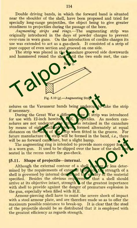
Augmenting strips and rings.—The augmenting strip wasoriginally introduced in the days of powder charges to preventover-ram in worn guns. On the introduction of cordite charges itsuse was extended to act as a gas-check. It consisted of a strip ofpure copper of even section and grooved on one side.
The strip was placed in the cannelure grooved side downwardsand hammered round the shell until the two ends met, the can-
Scale 1.
Fig. 5.10 (g).—Augmenting Strip.
nelures on the Vavasseur bands being undercut to take the stripif necessary.
During the Great War a different type of strip was introducedfor use with 12-inch howitzer H.E. projectiles. As modern can-nelures are not undercut, the strip was retained in the cannelureby means of eight inclined grooves formed alternately at equaldistances on the sides of the strip when fitted in the groove. Forfuture manufacture the strip will be formed in the band, i.e., therewill be no forward cannelure, but a slight hump.
The augmenting ring is intended to provide more copper for usein a worn gun. It used to be slipped over the base of the shell andseated in the recess under the gas-check.
§5.11. Shape of projectile—internal.Although the external contour of a shell is more or less deter-
mined by the requirements of external ballistics, the strength of ashell is governed by internal design and the quality of the materialspecified. Besides the obvious requirement that a shell shouldarrive at its objective intact, strength is of the greatest importancewith shell to provide against the danger of premature explosion inthe gun, especially when filled with H.E.
Armour-piercing shell have to resist the severe shock of impactwith a steel armour plate, and are therefore made so as to offer themaximum possible resistance to break-up. It is clear that the steelof the projectile should be so distributed that it is employed withthe greatest efficiency as regards strength.
Talpo.it
Talpo.it
Talpo.it

Copper Washers.
/ SleeveTROTYI„
Fig.5-II.
SHELL,B.L.,A.P.,WITH CAP,92 INCH GUN,MK XII BILL.
SCALE —1/4.
92 GUN )(IIBFZD LOT 35
7734 Ri2
6269---- Penetrative Cap.under
Ballistic Cap
Adapter.
Fuze. Base N°,346.
Locating Pins.
Guide Ring.
Screwed Ring.
Gas Check Cover Plate
Ring Securing.
Delay Setting Plug
Stop Screw
Filled Lot A/5) and o'a.te(actually on reverse side)
`^' Ballistic Cap.
937
958
Talpo.it
Talpo.it
Talpo.it

115
Internal design of head.—The usual practice is that the wall inthe head follows the external contour, keeping approximately thesame thickness of metal as at the shoulder. The metal is sometimesslightly thickened towards the fuze-hole in order to allow sufficientdepth to take the fuze, etc. The head thus forms a naturally strongstructure which is unlikely to fail on penetration of earthworks, etc.
As already mentioned, A.P. and semi-A.P. shell have speciallystrengthened heads which are hardened and in the former case arepractically solid. The projectile will, on arrival at the target, besubmitted to crushing forces acting in the opposite direction to thoseset up on firing, and a shell should be of such strength that it doesnot break up on impact, but bursts as a result of explosion initiatedby the fuze.
Base Adapters.—Base adapters are fitted to the majority ofbase-fuzed shell. They were introduced in order to give an apertureof increased diameter to facilitate manufacture. They also facilitatethe insertion of the container and the filling of the shell. Theirsizes generally approximate to the full bore of the cavity. Insome cases they may obviate distortion of the fuze and exploderingsystem at plate perforation (see Fig. 5.11). Base adapters havebeen used with H.E. nose-fuzed shell to facilitate manufacture, butthe manufacture of such shell has been discontinued in peace time ;a disadvantage of these shell is the difficulty of sealing the joint.
Base adapters are turned with a flange and are screwed externallyto fit the shell, the plain part in front of the thread having a reduceddiameter to accommodate the container, and they are bored andscrewed internally to take the fuze. The length of the externalthread on the adapter is determined by similar conditions to thosegoverning the strength of the base of the shell, but the thread andflange must also be of sufficient strength to withstand the impactof the projectile on the plate without allowing the adapter to setforward under stress of its weight and that of the fuze.
(See Appendices for the formulae that have been used in con-nection with the attack of armour.)
Fuze Sockets.—Shrapnel shell invariably have sockets, which aremade either of metal or steel.
Fuze-hole bushes.—In certain cases these are permitted as analternative to the solid head in H.E. shell. They are made of steel ;metal was permissible at one time, but its use is now discontinued.
§5.12. Capped shell.Caps of steel (see Figs. 5.20(b) and 5.08(b)), fixed over and
attached firmly to the head of the projectile, have been introducedfor armour-piercing (A.P.) and common pointed (C.P.) shell foruse against armour.
To perforate an armour plate, a shell has to punch its waythrough the thin hard face and the thick and tough supporting back.
Talpo.it
Talpo.it
Talpo.it

116
The object of the cap is to hold the head together at the moment itmeets the hard face, and so cushion the blow which tends to shatterthe point of the projectile, and there is consequently less tendencyfor the point itself to be broken or crushed. In a certain type ofcap the forward portion of the cap itself is hardened. This pene-trates the hard face of the armour and thus opens the way for thereal point, so further increasing the penetrating power of the shell.With a high striking velocity, at noinial impact, the cap is found toadd materially to the penetrating power of the shell against acemented plate, but the relative assistance given by the cap to theshell decreases as the striking velocity drops, and at low velocities,say under 1,000 f/s, becomes inappreciable.
There are various ways of attaching penetrative caps to shell :-
(a) By cotter pins. Tapered holes are formed in the head ofthe shell and cap, into which are driven cotter pins.
(b) By notching the cap into indents made in the head of theshell, usually about six.
(c) By pressing or rolling the cap whilst hot into an annulargroove.
(d) By interrupted raised ribs on shell and in cap.(e) By tinning the cap and the head of the shell at a temperature
of about 450° F., sweating them together, finally notching the skirtof the cap into indents of the shell.
Methods (a), (c) and (d) are not now employed.
§5.13. Shell for use in guns and howitzers.
Though guns and howitzers of the same calibre do not as a rulefire shell of the same weight, projectiles can be designed for use inboth types of ordnance, provided the difference in chamber pressureand in the twist of the rifling is taken into account.
Where both a gun and howitzer of the same calibre exist, thewords " GUN," " How.," or " GUN and How." are marked clearlyon the shell.
Heavy and Light Shell.
Certain guns and howitzers are issued with " heavy " and" light " projectiles. They are distinguished by the letters " H "and " L " stamped on the base and stencilled on the shoulder afterthe numeral of the shell.
§5.14. Manufacture of shell.
The manufacture of shell does not differ in general principle inthe various types. The normal method is by forging from steelingot or bar, though in certain cases such as practice and smokeshell the shell are cast direct to the required shape.
The steel is manufactured by the acid open-hearth or electric
Talpo.it
Talpo.it
Talpo.it

117
furnace processes, though for gun shell below 6-inch calibre and allhowitzer shell, the basic open-hearth process may be used.
The steel is top-poured into ingot moulds, after which the upperend of the ingot (about 25 per cent. by weight) is removed to getrid of piping. The fracture is then examined.
All casts and ingots are numbered. Each cast is analysed.The ingots are then issued. If more than one shell is to be madefrom the same ingot, the ingots are rolled to their approximatesection, and are fractured into their required lengths. The followingprocedure is then carried out on the ingot or billet :-
(1) Forged hollow by punching or drawing, limiting tempera-ture 1,150° C. The base of the ingot must form the baseof the shell, except with piercing shell where it formsthe head.
(2) Forgings gauged and examined for flaws. One per cent.of forgings are tested for mechanical properties.
(3) Surplus metal at the open end cut off, leaving the shell adefinite length.
(4) Base centred concentrically with interior cavity.(5) Turned on the exterior to plan dimensions.(6) Cavity bored out and the length of the shell corrected if
necessary. Shrapnel shell are only machined insidewhere the tin-cup and disc fit into the cavity.
(7) Base faced and open end tapered.(8) Bottling. The open end is heated and closed in under a
press.(9) Mouth faced and fuze-hole bored.
(10) Radius turning of head.(11) Thread of fuze-hole cut.(12) Weight adjusted by removing metal from the base.(13) Groove for driving band formed.(14) With H.E. shell, the base is recessed for base-plate.(15) Cavity cleaned by sand blast.(16) Preliminary examination.(17) Driving band pressed on.(18) Machining of driving band to plan dimensions.(19) With H.E. shell, base-plate fitted, caulked, or riveted.
NOT-E.—Base plates of H.E. shell are made of materialin which the grain runs parallel to the face of the plate,that is, at right angles to the axis of the shell.
(20) Base plate faced flush.(21) Cavity again sand blasted and varnished with copal
varnish.(22) Shell stoved at 300° F. to dry the varnish thoroughly.(23) Shell stamped and greased outside.(24) Examination and proof.(25) Shell painted.
Talpo.it
Talpo.it
Talpo.it

118
TYPES OF PROJECTILES
§5.15. Practice shot.Used for practice over sea ranges. These projectiles are usually
solid cast-iron of the same weight as the service projectile. A steelflat-headed practice shot with tracer has been introduced for tankpractice from the 3-pr. 2-cwt. gun over land ranges.
§5.16. Proof shot.For the proof of guns, howitzers, and charges. They are made
of forged steel of the same weight as the corresponding serviceprojectile, and are cylindrical in shape and flat-headed, so that theyshall not penetrate too far into the butt.
§5.17. Paper shot.
These are used to test the mountings of guns, which cannot,owing to their position, fire service projectiles in time of peace.They are designed to cause the same amount of recoil as a serviceprojectile and to break up in the bore. The body is made of woodpulp or rolled brown paper, and is filled to the correct weight withsmall shot and sawdust.
§5.18. Case shot.These generally consist of three or more long steel segments
held in position inside a thin tinned-plate canister, the whole beingfilled with bullets. The top and bottom are formed of steel plates,over which the serrated edge of the canister is turned. In thelarger natures the shot is strengthened by a central bolt. Theobject of this construction is to facilitate the shot breaking up onleaving the muzzle, allowing the bullets to scatter.
§5.19. Common pointed (C.P.) and common pointed capped(C.P.C.) shell.
General design.—These shell are designed for the attack oflightly armoured vessels, concrete emplacements, dug-outs, etc.,and are not intended to penetrate thick armour. They are madeof forged steel, and are usually about 3 .5 to 4 calibres in length.The walls are thicker than those of nose-fuzed H.E. shell, in orderto enable the shell to hold together on the shock of impact and topenetrate before bursting. The thickness at the point is not muchgreater than that of the walls, as the main consideration in designis to give as large a bursting charge as possible, and therefore alarge capacity, though latterly the tendency has been to make thehead slightly more solid.
C.P.C. shell were used in the larger calibres, 6-inch and above,and these shell have hardened points which increase their pene-trating power.
Talpo.it
Talpo.it
Talpo.it

Fig 5 19 (a).
METHOD OF FILLING:-SHELL Q.F.
COMMON POINTED 12 p
NON-BURSTER BAG TYPE.
Talpo.it
Talpo.it
Talpo.it

F 9 . 5 19 (D).
COMMON POINTED SHELL WITH CAP FILLED POWDER.
waran
matomoo
wow
Talpo.it
Talpo.it
Talpo.it

119
Shell with hardened points are liable to spontaneous cracks.They are therefore subjected to a keeping trial in the open to allowlatent cracks to develop after hardening and before final acceptance.
Filling of C.P. and C.P.C. shell.—C.P. and C.P.C. shell may befilled either with gunpowder or H.E.
In the case of gunpowder fillings, with C.P. above 12-pr., the
FIG. 5.17.—Paper Shot.
powder bursting charge is enclosed in a dowlas bag, the neck beingmade of shalloon to facilitate ignition, as shalloon is more permeableto flash. The base of the shell is packed with primers filled powderto make a compact filling and facilitate ignition by the fuze. C.P.C.shell are lined with copper containers to prevent accidental prema-tures through spontaneous cracking of the head. C.P. shell 12-pr.
Talpo.it
Talpo.it
Talpo.it

120
and below differ from the remainder in that there is no dowlas bag,the powder being poured straight into the shell and there are noprimers.
C.P. shell are coated internally with a special paint, " velvril,"in order to prevent friction between any loose powder and thewalls, causing a premature. For a similar reason the inside of thecopper container in a C.P.C. shell is varnished.
The nature of the powder used for filling C.P. and C.P.C. shellIS :—
Q.F. up to 6-pr. G.12.Q.F. 12-pr. and above
P.3 and G.12.
• Primers are filled with
G.12.In the case of H.E. fillings except C.P., the shell are fitted with
an aluminium container, the interior of which is coated with copalvarnish.
The 6-in. C.P.B.C. is filled with a mixture of trotyl and beeswaxin the proportion of 93 to 7, a block of R.D. composition 1006being first inserted into the apex of the container.
A cavity lined with a paper tube is formed in the filling to re-ceive the exploder system consisting of two 24-oz. pellets of trotyl.Fig. 5.20 (c), showing filling of 9-2-in. A.P.C., is almost identical with6-in. C.P.B.C., except that the trotyl surround is omitted.
Closing the bases of C.P. and C.P.C. shell.(a) C.P. shell are screwed internally to take the fuze or plug,
and in some cases a steel bush is fitted.(b) C.P.C. shell are fitted with a base adapter, large enough for
the copper or aluminium container to be inserted.NoTE.—C.P. shell filled powder or H.E. do not have containers,
as the points are not hard.The closing of the base of a C.P. or C.P.B.C. filled H.E. is
similar to that of an A.P. shell filled H.E.
§5.20. Armour-piercing (A.P.) and armour-piercing capped(A.P.C.) shell.
General design.—The definite object of these shell is to perforatearmour and then burst effectively ; every other consideration issubordinated to this end. At proof a successful shell is one thatperforates the plate and emerges at the other side with the cavityfor bursting charge intact.
To attain this purpose an A.P. shell is made of forged or caststeel, and has a pointed and solid head which is specially hardened.The walls are considerably thicker than those of C.P. shell to enablethem to withstand the shock of impact, and are of toughened steel,in order to afford greater tenacity to ensure the shell holding togetherwhen striking hard-faced armour, especially at oblique impact. Itscapacity is small in comparison with C.P. shell, as this is sacrificedin order to provide strength for perforation.
Talpo.it
Talpo.it
Talpo.it

METHOD OF
Fi g5• 19(0.
B.L . C.P.FILLING:- SHELL
(TYPICAL)1
FOR 6 GUN , 6 HOWITZERS g. ABOVE .
/' 8' H OW
: FUZ ED
/ EXPR BAG
LOT
70
IA
1_01-36\
4o1
71
:
FIELD SERVICE.
Shelbte.
Exploder
(Picric Powder)
Paper Tube
-F/x/ng Screw.
Shellite
Base Fuze N."16.
Molten
i
g
\ii i ... i
:30
-'-I
M
ui if_
w7
--fiallM
, ).
kV
WNW.-......-.
=-17-4.---
I I-41111a = ,• N
I
SHOWING
ENLARGED VIEW OF BASE,DETAILS FOR SEALING GAS PRESSURE.
.958
Talpo.it
Talpo.it
Talpo.it

Copal Varnish
Lasting Cloththirster Bag
Blank L.G.(G./2)
7Dram Primers
Plug BaseShe//
Fig . 5.20(a).
ARMOUR PIERCING SHELL FILLED POWDER.
Talpo.it
Talpo.it
Talpo.it

H. E. EXPLODER. (TOP.)\ H.E. EXPLODER. (BOTTOM.)
ALUMINIUM CONTAINER.TROTYL SURROUND
BOXCLOTH DISC,GLAZEBOARD DISCS.
FELT WASHERBASE FUZE.
TWO CLOTH DISCS.
121
The c.r.h. of an A.P. shell is small, about 1 .6 calibres, as the holethrough the armour has to be punched as quickly as possible inorder that the striking velocity may not be entirely lost before theshell gets through.
Owing to the hardening process to which the heads are subjected,they are liable to spontaneous splits. A.P. shell are stored, there-fore, in the open for three months before final acceptance, to allowany latent crack to develop.
A.P. capped shell (see page 115) are used with the larger calibres,6-inch and above. *
Filling of A.P. and A.P.C. shell.—A.P. and A.P.C. shell wereformerly filled powder, and stocks of powder-filled shell are still
BLOCK OF R.D COMPOSITION N91006.TROTYL /BEESWAX. COPPER WASHERS.
PAPER TUBE.
FIG. 5.20 (c).
held in the coast defences. In future, however, the filling will beH.E. There are also a number of shell in existence filled lyddite.The present approved filling for this type of shell is, however,trotyl or a mixture of trotyl and beeswax.
The filling of A.P. shell with powder is very similar to that ofC.P. shell. The differences are :-
(a) Lasting cloth is used instead of dowlas, as it is closer intexture. There is no shalloon neck.
(b) G.I2 is used instead of P.3 mixture.A.P.C. shell filled powder are similar to A.P. shell, but have
less capacity. There are no copper containers.
* For further information on the attack of armour, see Appendices.
Talpo.it
Talpo.it
Talpo.it

122
A.P.C. shell filled H.E. are lined with an aluminium containerto guard against premature detonation due to spontaneous crackingof the hardened head. A cavity is left in the base of the filling,lined with paper, into which is placed an exploder containing picricpowder for lyddite or shellite fillings, and trotyl for trotyl fillings.The space left by the shrinkage of the filling is filled with beeswaxcomposition ; 3-pr. A.P. shell are filled lyddite without a container.
Armour-piercing shell with cap, filled H.E., Trotyl and Bees-wax. (Fig. 5.20 (c).)
Fig. 5.20 (c) shows the latest type of A.P.C. shell ; it is alsotypical of the 6-in. C.P.B.C.
There exist, however, several earlier marks which will be foundto differ in details regarding adapter fittings.
Closing the base of A .P. and A.P.C. shell (gunpowder filling).—A.P. and A.P.C. shell filled powder have a steel bush screwed intothe base, which is screwed internally to take the fuze or plug.
Closing the base of all pointed H.E. shell (except 3-pr.).---Pointedshell are fitted with a base adapter of approximately the samediameter as the cavity.
The base of the fuze, or plug, is covered by a copper gas-checkplate to prevent the propellant gases penetrating through or overthe fuze or plug. The gas-check plate is held in position by a basecover plate consisting of a perforated steel plate and screwedring, which engages with a thread cut in the adapter. Gas-checkplates are essential for these shell.
§5.21. Semi-armour-piercing (S.A.P. and S.A.P.C.) shellH.E.
These shell are intended for use against lightly armoured vessels,such as submarines and light cruisers. They are similar in designto A.P. shell, but there is less material in the head, and thecapacity is greater. Their penetrative power is superior to that ofC.P. They are filled lyddite or trotyl, and the base is closed in asimilar manner to other pointed H.E. shell.*
§5.22. High explosive (H.E.) shell.Design.—H.E. shell are designed to cause damage to material
by the force of their burst, or to personnel and aircraft by fragments.Against earthworks, etc., the main consideration in design is
that the bursting charge should be as large as possible. Forexample, in a large mortar bomb, the weight of the charge forms a
* NOTE.—A table showing the fuze for each type of shell will be found onpage 201.
A list of service plugs will be found in R.A.O.S., Part II, Pamphlet No. 1,Appendix VIII.
Talpo.it
Talpo.it
Talpo.it

9.ZGUNCato
rUZIED 1.0 -r P3
X121/ 13AC4
LOT 15(3
AluminiumContainer
Lyddite
Exploder PP
Composition.Beeswax
-Fuze Base AP/6.
Gas Check Plate
Fig. 5 . 2 0 (b).
ARMOUR PIERCING SHELL WITH CAP FILLED H.E.
Ring Securing Cover Plate
955
Talpo.it
Talpo.it
Talpo.it

11111Vimuftalitom
0 %,
F i g . 6 254).
FUZE, TIME PERCUSSION.N° 80,Mkc
trek
(r4a/ 011 .-L:joiriliImirrats
I all IMAM IliVar
Top RingFuze Powder.
Ferrule 1/*L Yll
Vegetable Paper
Stirrup Spring
!ar Washer.
Percussion.- MI 774 Bottom Ring
III Creep Spring.
Percussion PelletLeather Washer
itDetonator 2 . 99 Grain.
Box Cloth Washer
Linen Cambric Disc. — Ca- Percussion Pellet.R.PPor 6.20.Powder.
Base Plug -
Screw Plug.
Brass Washer.
Filling Hole Plug.
G/az eboard Washer.
Linen Cambric Disc
* Including 16 6rs.R.P.
Si/k or Tycoon PaperTab/et.
Powder Pellets
Set Screw, Cap. --
Time Pe/let Plug
Cover.
Time Pellet.
Stirrip Spring.
Detonator •62 Drain.Including P 876r)Pin Securing Top Ring.
Needle
958
Talpo.it
Talpo.it
Talpo.it

—First two DivisionsBlacked out
Fig 6-25(b).
FUZE, TIME N° 80/44 M K V /0.
- / /nch T Stene://ed in Blue.
956
Talpo.it
Talpo.it
Talpo.it

(19 20 2:1 22
Rustless Steel11. Setting, Pin.
F19.6-26.
FUZE ; TIME & PERCUSSION,
N o 88 MK VI/L/.
Cap.
Tine Pellet.Detonator /-62 Grain.
Top Ring.
Need/e,Rustless Steel
Lead WasherFuze Powder.Steel Ball,Nic.ke/Plated or of RustlessSteel.
Fuze Powder.Paper Washer.Boxcloth Washer.
- FerrulePercussion Pellet & Plug
Cap. Percussion PelletBody.
P or 6" 20 Powder
z Base PlugLinen Cambric Disc
Time Pe//et Spring.
5i/k or Tycoon Tablet.
Powder Pellets
Stirrup 510 rifqDetonator/ 7Grain
Leather WasherCreep Spring.
6/azeboard Washer.Linen Cambric DiscBetween /'Masher andScrewed Plug:
Washer.
'1>
Talpo.it
Talpo.it
Talpo.it

189
sets back, straightening the arms of the stirrup spring, and travel-ling on, forces itself over the pellet to a rim at the base ; the creepspring prevents any forward movement of the percussion pelletduring flight.
On graze or impact, the percussion pellet flies forward, over-coming the creep spring, and carries the detonator on to the pointof the needle. The flash passes through the pellet and fires themagazine.
Safety arrangements.—When the setting on the lower time ringis opposite the red cross on the body, i.e., when the fuze is set atsafety, the flash holes to the lower time ring and to the magazineare masked by the bridges of the upper and lower time rings,respectively. This provides a double safety against ignition of themagazine, should the lighting mechanism act prematurely.
Fuzes should invariably be set safe during transport of ammuni-tion. If rounds, of which the fuzes have been set, have to travel,then the fuzes must be re-set to safety, not to zero, in order to ensuresafe transport of the ammunition.
The lighting pellet is protected by the cap of the fuze. Althoughthis protection is sufficient for ordinary usage, yet it is possible forthe fuze to be fired if the round is dropped heavily on to the cap,particularly if it be a fuze of which the cap is made of aluminium.
It is important, therefore, that the rounds should be handledwith care, and that the fuzes should be set at safety during thetransport of the ammunition.
§6.26. Fuze, time and percussion, No. 88, Mk. VI.
In general this fuze is similar to No. 80 fuze previously described.The main differences lie in the mechanism of the lighting and
percussion arrangements.The time rings are similar except that the lower ring is filled
with R.D. 202 composition, which gives the fuze a total time ofburning of 48 seconds. The graduations, however, remain thesame, 0 to 22. The lower ring is lacquered red.
Time mechanism.—The pellet with the detonator is supportedby a coiled spring, which is strong enough to ensure safety duringtransit. There is a considerable distance between this detonatorand the needle.
Percussion mechanism.—The percussion pellet with detonatoroccupies a central recess in the lower part of the body.
A stirrup spring, fitting over the top of the pellet, supports aferrule, which keeps the detonator at a distance from the needle.
A metal ball is interposed between the pellet and the top of therecess.
A creep spring rests on the flange round the base of the percussionpellet.
Talpo.it
Talpo.it
Talpo.it

190
Action of the time mechanism.—On discharge, the pellet setsback, overcoming the coiled spring, and carries the detonator onto the needle. The further action of the time mechanism is similarto that of the No. 80 fuze.
Action of the percussion mechanism.—The acceleration on firingcauses the ferrule to set back over the pellet, straightening out thearms of the stirrup spring.
The rotation of the projectile causes the metal ball to fly outinto a recess in the body.
" Creeping " during flight is prevented by the creep spring.On impact, the pellet flies forward, compressing the creep spring,
and carries the detonator on to the needle.
Safety arrangements.—The safety arrangements of the timemechanism are similar in principle to those of the No. 80 fuze.
The percussion mechanism has an additional safeguard in themetal ball, which ensures that the detonator cannot be touched bythe needle until the ball has been moved clear by the action ofcentrifugal force.
In the earlier Marks of the fuze, the percussion needle was spunin, but in this Mark the needle is screwed in from the top. By thisconstruction the needle is more firmly held and is capable of with-standing the forces set up on firing.
In the Mk. III, the time mechanism was placed eccentricallywith regard to the axis of the fuze. There were, in consequence,two needles.
§6.26 (a). Fuze time and percussion, No. 220 Mk. I.The fuze is a tension type of 2-in. gauge.The time portion is similar to that of the No. 199 fuze, but is
located to one side of the centre line of the fuze.The percussion arrangement is in the centre line of the fuze,
and resembles that of the No. 101E fuze. The needle pellet is pro-vided with a flash groove passing round the sides and bottom, sothat on graze the flash has easy access to the magazine.
The dome shaped cap is fixed after tensioning by two set-screws.
When in the shell, a copper asbestos washer fits under the flange.The top ring is filled with 30-second powder whilst the bottom
contains R.D.202 ; the latter is therefore lacquered red.The Mark II fuze differs only in the graduations, which are
from 0 to 22.
§6.27. Fuze, time, No. 199, Mk. III.This fuze has been introduced for anti-aircraft guns.The various components and general structure of the fuze are
shown on the diagram. The body and base plug are of unrestricted(class " G ") metal.
Talpo.it
Talpo.it
Talpo.it

-911111MMnEP"-
Mak
40 42 44\\\\\\0 2 4. 6
Percussion Detonator 2 55 yes
Creep Spring
Needle.
Centrifugal Bolt
Detent
Detent Spring.
Percussion Needle Pellet
Detent Plug ---
6' 20 Powder
Linen Disc.
Cap.
Tim Detonator Holder.-,
Time Detonator 255 yrs
Top /me Ring.
Bott m Time Ring.
Bod
5pri
Need e
Time Needle Pellet.
Base Plug.
Fi g . 6• 26(a). FUZE TIME AND PERCUSSION , N9 220 MARK I. C.
FULL SIZE.
ELEVATION. Detonator Play SECTION 6.B. SECTION C C C .
Brass Washer.Scre we d Plug.
DURING FLIGHT. ON CRAZE.
SECTION A A.
B
Talpo.it
Talpo.it
Talpo.it

ri_w,59-24.4*-A\
-Band securing Cover.Cover Ring.
Cap.
Boxcloth Disc..
Detonator Holder.
mei ,Set Screw. =MB fjj1,_Detonator, 2 Grains. p
r
Powder Pellet.
Paper DiscPaper Ring -
Plug, Mechanism Hole.
----- Screw,securing Cap.
Securing Ring. Pin securing Top Ring.
-Top Ring. Bottom Ring.
-Spring. Fuze Powder Needle
G.20 Powder. Washer.
-Body. Base Plug.
Mealed Powder.
Fig. 6'27.
FUZE. TIME, N9 199 M IS III WITH COVER.
Linen Disc.
Brass Washer
Filling Hole Plug.
0 I 2 3 4 5 VI 3
Malty & Sons,Lith338;
Talpo.it
Talpo.it
Talpo.it

191
The method of manufacture and filling is similar to thatdescribed for Fuze, T. & P., No. 88, except that there is no per-cussion arrangement ; the detonator is filled two grains detonatingcomposition " B " mixture and G.20 gunpowder and the time ringsare filled with a fuze powder of new composition to give a time ofburning of 25 seconds. The upper ring is prevented from rotatingby a single brass pin. Both rings have a setting slot.
There is a two-way channel leading from the lighting pelletchamber to the upper ring to allow the flame and gas from thedetonator to circulate in the body of the fuze and so cause theignition of the time ring to be less violent.
The markings round the fuze body are graduated 0 to 30.Mk. I has small setting slots in top and bottom ring and the
graduations are round the top ring.Mk. II has widened setting slots in both rings and certain
minor structural differences, otherwise as Mk. I.Mk. III is similar to Mk. II except that the graduations are
transferred from top ring to flange round the body.Mks. I and II are now obsolescent.
Action of fuze.
Similar to that described for time mechanism of Fuze, No. 88.
§6.28. Mechanical fuzes.Mechanical fuzes are time fuzes in which the time to burst is
controlled by mechanical means in place of the burning away of atrain of composition.
They may be divided into two distinct types :-(1) Mechanical time fuzes, such as No. 203.(2) Mechanical distance fuzes.
Advantages of mechanical fuzes.—In general the advantages ofmechanical time and mechanical distance fuzes over the ordinaryburning or composition time fuzes are :-
(a) The absence of irregularity in time due to inherentvariation in the time of burning of batches of powder,and the detrimental action of the slag produced bycombustion.
(b) The absence of variation caused by dynamic pressure atthe escape holes of ordinary time rings and the rarifica-tion of the atmosphere at high altitudes. This is ofimportance in the case of fuzes fitted to shell fired athigh angles of elevation against aircraft flying at con-siderable altitudes.
(c) The absence of variation in the rate of burning at highaltitudes owing to the lowering of atmospheric tempera-ture.
Talpo.it
Talpo.it
Talpo.it

192
(d) The effect of spin is not so great at high spins as it is inthe case of combustion fuzes.
(e) In the case of mechanical time fuzes, it is possible to testeach individual fuze for time. This can only be donein the case of a combustion fuze by destroying it.
(f) Age should not affect a mechanical fuze, and in any caseit can be tested for time-keeping at any period in itslife and re-regulated if necessary. Nothing can be donewith aged combustion fuzes, which burn irregularly.
Disadvantages of mechanical time fuzes.
(a) They are, at present, expensive to manufacture, but thismay be more than compensated by the life in store.
(b) The mechanism is affected by spin when the spin is high,but perhaps not to the same extent as a combustion fuze.
(c) Possible loss of tension in springs in storage, but there isnot yet sufficient data on this point. The Germansexperienced no loss of tension after ten years.
(d) Possible deformation in high velocity guns, but this pointawaits proof.
§6.29. Mechanical time fuzes.
In this type the mechanism is designed to run at a predeter-mined rate after the fuze has been armed, this rate being littleaffected by the rotational velocity of the projectile in which it isfired.
The time of running or time of burst is, therefore, practicallyconstant in any type of gun or howitzer. Consequently, the designhas the advantage over others in that it is capable of being used innearly all equipments, provided the time of flight is known, eventhough the range table does not include a scale for the actual fuze.
There are several different mechanical time fuzes in existence inthe service, differing only slightly in their general make-up.
No mechanical types are at present in general use in the landservice. A general description of Fuze, No. 203, is given. A list ofthe others is appended showing their essential differences from No.203 fuze.
§6.30. Fuze, time, No. 203, Mk. I.
This fuze, designed to burst a shell at any interval of time up to60 seconds after the firing of the gun, consists primarily of threeparts :-
(a) The body.(b) The magazine in the base of the body.(c) The clockwork mechanism.
(a) The body consists of a metal base piece, screw-threaded tothe 2-inch fuze-hole gauge, and provided with a flanged platform
Talpo.it
Talpo.it
Talpo.it

N9 203
Hand; -
Screwed Collar\
Top PlateBarrel Plate.
Train Plate. -----
Bottom Plate. -
Wire Ring.-
Cap.
1-/and Centre.
Dome.
Locking Ring.
Copper Wire Rivet
Detonatof;39rs;1itlixt
Fig. 6 . 30 (a).
FUZE, TIME, N. 203, MK I.
.5 /0 /5 20 25 30
4
Base Piece.-- ---
70 Grains F. G. Powder./
Washer.
'Linen Disc
Base Plug.
& Sons,l.th95,
Talpo.it
Talpo.it
Talpo.it

193
on which rests the dome with steel cap attached. The cap is conicaland brought up almost to a point in order to continue the streamlinecontour of the shell into which the fuze fits.
At the top of the dome is a race-way, known as the " hand-race," which consists of a perfectly flat, smooth band of metal intrue vertical relationship with the platform of the base-piece. Thishand-race is slotted to accommodate the " hand."
Inside the dome, below the hand-race, a locking ring is held inposition by means of three copper wire rivets passing right throughthe wall of the dome and the thickness of the ring. The lower edgeof the ring is recessed so as to leave only a thin rim of metal. Fivehollow-edged pins, which come immediately under the thin rim ofthe locking ring, are secured in the platform of the base-piece.
The dome is held in position by means of a screwed collar, whichscrews down into the flange of the base-piece, housing a tensioningwire between it and the flange provided at the base of the dome.The screwing down of the ring on to the tensioning wire regulatesthe turning movement necessary to rotate and set the dome. Thisturning movement is fixed at 250 inch-ounces plus or minus 25 inch-ounces.
(b) The underside of the body is hollowed out to form themagazine, and a hole through the diaphragm thus formed betweenthe magazine and platform is bored and screw-threaded to take thedetonator plug. Holes are also drilled to allow of the passage ofthe holding or anchoring screws of the clockwork mechanism.
The detonator is an ordinary igniferous detonator filled threegrains Detonating Composition " A " mixture, and the magazine ispowder filled and closed by a base plug in the usual manner.
(c) The " action " is a piece of unjewelled clockwork mechanism.It consists of a train of wheels operating a hand, the motive powerbeing supplied by a mainspring. The hand itself is capable ofrising out of its normal position under the influence of a spring, andis the main factor in the functioning of the fuze. The hand isdouble-ended, and is mounted on a hollow centre, the rim of whichembraces a lip on the end of the striker lever. The striker lever isreleased by the rising of the hand. The shape of the hand is such as toallow it to rise vertically when it reaches a definite angular positionof coincidence with the recesses in the hand race.
The method of regulating the movement is based on the present-day watch-making practice, but the mode of application is different.In this mechanism a pallet and straight length of steel spring orphosphor-bronze ribbon take the place of the balance wheel andcoiled hair-spring.
The pallet consists of four arms, two upstanding in such anangular position as to engage the teeth of the 'scape-wheel, theother two being flat and in a straight plane with the base plate ofthe movement. A small brass weight is placed at each end of the
7_(1342)
Talpo.it
Talpo.it
Talpo.it

194
latter pair of arms in order to regulate the rate of oscillation of thepallet by the adjustment of the measure of weight.
The rate of oscillation is controlled by the straight hair-spring,which is secured centrally through the arbor carrying the pallet.The hair-spring has one end housed so as to be free to move radiallyin a saw-cut in the bottom plate of the movement, and the otherend similarly secured in a radially adjustable block, which can beadjusted until the free length of hair-spring is such as to ensure thecorrect rate of oscillation of the pallet and therefore the correctrate of movement of the rotating hand.
The normal rate of oscillation is 87 .98 complete beats asecond.
The mechanism is anchored to the platform of the base piece byholding screws, and also embraces a number of safety devicesdescribed below.
Safety arrangements.—The main safety arrangements employedare as follows :-
(a) The safety catch (or centrifugal safety catch) to maintainthe striker in the unarmed position.
(b) Trigger safety catch to prevent premature arming.(c) A shearing pin to maintain setting at safety in storage
and transit.
(a) The centrifugal safety catch is housed under the cam on thestriker and serves a dual purpose-
(i) In the event of the movement being accidentally set inaction, the striker, owing to its being upheld by theinterposing catch, is prevented from reaching thedetonator.
(ii) If a fuze in this condition were loaded into a gun and thegun fired, the catch would be prevented from swingingout from under the striker, because the latter wouldimmediately jamb down on to a step cut in the catchfor that purpose, and hold it firmly in place.
(b) The hand is secured against movement by means of a triggerpivoted on the top plate of the movement at one end, the oppositeend being provided with a lip of overhanging metal, which engagesthe hand and retains the trigger in position. The trigger, beingfree to move up and down, is controlled by means of an eccen-tric screwed to the top plate and overlapping the edge of thetrigger, thus preventing any tendency of the trigger to rise underthe influence of the hand spring. It has, of course, to descend inorder to free the hand, but once down it must not be allowed toreassert itself due to rebound. This is countered by a small lockingbolt which functions under the action of a spring immediately ondescent of the trigger.
A trigger safety catch is housed under the trigger in order to
Talpo.it
Talpo.it
Talpo.it

Fig. 6-30 (b).
FUZE, TIME, N9 203, M K I .
Hand race- -Hand centre.
Centre Arbor
- Hand
,c Trigger.
Lever
Locking Bolt
Trigger Safety Catch
StrikerSpring----
Striker
Cam_
Pillar--
PafietHair Spring
Centrifugal Safety Catch------.
--Adjuseable Block
mar
Hand '-Spring
SECTION A.A.
Malby 8 Sons,lith
Talpo.it
Talpo.it
Talpo.it

195
prevent its being prematurely functioned. The catch is withdrawnimmediately the fuze is set away from the safety mark.
(c) The shearing pin of copper passes through a small hole inthe flange of the base piece and dome, and is for the purpose ofpreventing the possibility of the dome being accidentally moved intransit after being issued set at safety.
Assembled fuzes.—The clock is fully wound before being securedin position in the body. The striker point is immediately abovethe centre of the detonator.
The dome and base piece carry setting dots for use with a fuzesetter, the setting depending upon the relative positions of thehand of the movement and the dome hand race slots.
The fuze is waterproof to prevent ingress of moisture, and issecured against interference as regards its tension by locking thescrewed collar in position after tensioning the fuze.
Action.—On firing, the locking ring in the dome shears itssuspending wires and sets down on to the steel pins in the platformof the base piece, thus locking itself and preventing any shifting ofthe dome from the position it was set in, by reason that a feather orguide pin in the dome engages a slot or featherway in the lockingring. The trigger descends and is caught by the locking bolt,releasing the hand : during acceleration in the bore it is unlikelythat the pallet will oscillate owing to the force of " set-back " ;when the muzzle is reached the hand begins to rotate under theinfluence of the mainspring. After acceleration ceases, the centri-fugal safety catch, flying out under the influence of centrifugalforce, leaves the striker supported only by its cam resting on thesloping surface of the pillar provided for the purpose.
The fuze having reached its setting, the hand is brought imme-diately under the slots in the hand race into which it rises underthe influence of its spring, and releases the lever controlling thestriker. The lever flies outwards owing to centrifugal force, andthe action of the striker spring turns the cam of the striker off thepillar, the sloping surface of the latter facilitates this action, andthe striker fires the detonator and the powder magazine.
The other mechanical fuzes are :—
§6.31. Fuze, time, No. 200.This fuze differs from No. 203 in respect of the dome-locking
device, and in being without a safety catch under the trigger.The clock is contained in a clock case having a flanged base, and
the pins are affixed in the locking ring instead of in the fuze plat-form. The locking ring is also suspended by springs instead ofshearing wires.
On firing, the locking ring sets out of the springs, the pinspuncture the clock case rim, and thereby lock the dome, as in thecase of No. 203.
Talpo.it
Talpo.it
Talpo.it

196
Fuze, time, No. 201.This fuze is identical with No. 200 except that it is timed to run
85 seconds instead of 60. So far, none have been made and formalapproval is still withheld.
Fuze, time, No. 202.This fuze is identical with No. 203, but is for use in naval
service only.
Fuze, time, No. 204.This fuze consists of the No. 200 mechanism made in France,
fitted with centrifugal safety catch as in No. 203 (i.e., locking step)and fitted to bodies pertaining to the No. 203 design.
Fuze, time, No. 205.Is similar to No. 203, but with contour for use with 3-inch
20-cwt. 16-lb. shell.
Fuze, time, No. 206.Differs principally from the No. 202 fuze in being fitted with a
modified clock mechanism giving a running time of 45 seconds.The bottom ring is graduated in seconds and marked 0-225, thefigures representing the number of 1/5th seconds of time. Thefuze is fitted with a cover similar to that for the No. 202. It isused in the naval service.
Fuze, time, German, converted, Dope Z16.It was from this fuze that the No. 200 was developed. It is
identical for all practical purposes with the No. 200, except asregards the fuze-hole gauge. To render it suitable for use with the2-inch fuze-hole an adapter is necessary. It is also fitted withcentrifugal safety catch of the No. 203 type (i.e., locking step).
§6.32. Mechanical distance fuzes.Under this heading are included those fuzes in which the time
burst depends on the distance travelled, or more strictly on thenumber of revolutions the fuze makes about a spindle which passesthrough its axis. The spindle is held against rotation by means ofvanes, or by the attachment of some pendulous weight or similar" inertia " member.
This type of fuze is therefore inoperative until fired. Its timeto burst is dependent upon and varies with the muzzle velocity,the pitch of the rifling, and the calibre.
This design requires no self-contained driving force such as amainspring.
On the other hand, the necessity for the projecting vanes orother exterior inertia member introduces, in the majority of cases,a grave risk of failure due to injury during loading.
No fuzes of this type yet exist in the land service.
Talpo.it
Talpo.it
Talpo.it

197
PRESERVATION OF FUZES
§6.33. Effect of climate.Fuzes deteriorate when exposed to damp, and climatic con-
ditions affect fuzes adversely, especially abroad in hot moistclimates.
The injury is permanent and tends to increase with time,although there may be no further exposure.
Moisture acts on the detonators, and, if they become affected,blinds or unsatisfactory bursts may result. Damp also acts on thecomposition of time fuzes. It may lengthen the time of burning,prevent ignition, lead to a premature functioning of the fuze, orcause the rings to become so tight that they cannot be set by hand.This latter defect is frequently met with in time and time andpercussion fuzes of war-time manufacture. It is caused by thecomposition in the time rings swelling and thereby taking a firmgrip on the boxcloth washers.
Dampness also corrodes the bodies of fuzes, especially thoseparts made of aluminium. It rusts or corrodes safety pins, makingthem difficult to withdraw.
In mechanical fuzes moisture disturbs the harmonious workingof the clock. Precautions have, therefore, to be taken to protectfuzes, particularly time fuzes, from damp.
§6.34. Fuze Cylinders.Fuzes, when issued separately from shell are packed in tinned-
plate cylinders. The lids are hermetically sealed by a tin stripsoldered on, and the cylinders are vacuum tested before issue.
In certain cases where fuzes are only to be issued to home units,the lids are tape-banded, i.e., sealed by a piece of tape shellaced on.
Each cylinder has a label on the top, showing the number,nature, Mark, filled lot number, date of filling and packing, and thefiller's initials.
Painting of fuze cylinders.—Fuze cylinders containing time andtime and percussion fuzes having the 2-inch gauge are paintedgreen. Those containing detonating fuzes are painted yellow. Allother cylinders are painted black.
§6.35. Waterproofing and sealing of fuzes.All openings in percussion fuzes are coated with R.D. cement
or waterproofing composition to prevent the ingress of damp.In all the latest time and time and percussion fuzes, the spaces
between the cap, time rings, and body, also the set-screw recess ofthe cap, and the escape hole discs in the time rings, are now water-proofed with a composition of beeswax, mineral jelly, and frenchchalk.
Talpo.it
Talpo.it
Talpo.it
198
The base plugs are waterproofed by having the threads coatedwith R.D. cement before being screwed in, and then the whole ofthe base is covered with R.D. cement.
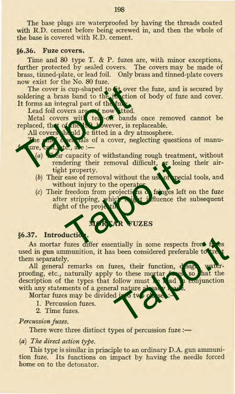
§6.36. Fuze covers.Time and 80 type T. & P. fuzes are, with minor exceptions,
further protected by sealed covers. The covers may be made ofbrass, tinned-plate, or lead foil. Only brass and tinned-plate coversnow exist for the No. 80 fuze.
The cover is cup-shaped to fit over the fuze, and is secured bysoldering a brass band to the junction of body of fuze and cover.It forms an integral part of the fuze.
Lead foil covers are not now fitted.Metal covers with tear-off bands once removed cannot be
replaced, that of the 199. however, is replaceable.All covers should be fitted in a dry atmosphere.The chief essentials of a cover, neglecting questions of manu-
facture, cost, etc., are :-(a) Their capacity of withstanding rough treatment, without
rendering their removal difficult, or losing their air-tight property.
(b) Their ease of removal without the use of special tools, andwithout injury to the operator.
(c) Their freedom from projections or fringes left on the fuzeafter stripping, which might influence the subsequentflight of the projectile.
MORTAR FUZES
§6.37. Introduction.As mortar fuzes differ essentially in some respects from fuzes
used in gun ammunition, it has been considered preferable to treatthem separately.
All general remarks on fuzes, their function, design, water-proofing, etc., naturally apply to these mortar fuzes, so that thedescription of the types that follow must be read in conjunctionwith any statements of a general nature already made.
Mortar fuzes may be divided into two classes :-1. Percussion fuzes.2. Time fuzes.
Percussion fuzes.There were three distinct types of percussion fuze :-
(a) The direct action type.This type is similar in principle to an ordinary D.A. gun ammuni-
tion fuze. Its functions on impact by having the needle forcedhome on to the detonator.
Talpo.it
Talpo.it
Talpo.it

Fig. 6.38.
FUZE, PERCUSSION, D.A. N9 138,W I/L/WITH CAP. SCALE-VI .
Key formed onStriker Head
PLAN WITH CAP REMOVED.,
Derma tine Washer. —
Recess for Key.
Striker Spindle.----
Gauge /.375
Needle.
Distance Pin.
C. E. Stemmed.
Paper Disc.
C. E. Pellet.
Shalloon
Safety Spring.
Safety Cap.
Split Pin
Striker Head.\
Striker Spring.
Set Screw.
Locking Pins.
Guide Bush.
Arming Sleeve.
Arming Spring.
Retaining Sleeve.
Six Balls.
Set Screw.
Hinge Pin.
Magazine.
'lassit#110O
Detonator.(5 Grs)
Shutter.--
Shutter Spring.
AHinge Pin.
SECTION B-B.
LOOKING IN DIRECTION OF ARROW.
Talpo.it
Talpo.it
Talpo.it

199
(b) The all-ways type.
This type has the capability of functioning as soon as any partof the cylindrical bomb, to which it is fitted, strikes the ground.The fuze itself need not be touched by the impact. This type isnow obsolete.
(c) The pistol type.
This type only contains the mechanism of a fuze ; it is used inconjunction with a detonator carried separately in transport, andfixed into the bomb itself when preparing for action. It is nowobsolete.
Three percussion fuzes exist for mortars at present. Theseare :-
Fuze, Percussion, D.A., Nos. 138, 139 and 139P, and areused in the vaned type of 3-inch mortar bombs.
§6.38. Fuze, percussion, D.A., No. 138, Mk. I.The construction and action of this fuze is generally similar to
the No. 117 described on page 169.In the design of mortar fuzes which are to be fitted with shutters
to render them safe in transport and during acceleration in thebore, the following points should be considered.
(i) In a mortar the chamber pressure available for arming afuze is relatively of a low order—usually under 2 tons to thesquare inch—and, further, the acceleration period is of shortduration.
(ii) As the mortar is smooth bore, no spin can be imparted tothe bomb ; neither is it possible for practical considerations totwist the vanes, as stability in flight and air resistance must betaken into consideration.
The general differences from the No. 117 fuze are given below(see also Fig. 6.13).
The shutter containing a five-grain fulminate detonator is heldagainst the shutter spring by the point of the striker.
The arming sleeve surrounds the striker and retains six steelballs in a seating, these together with the sleeve and armingspring retain the striker, and therefore the shutter, in the safeposition.
Above the guide bush is the striker head, striker spring, splitpin, two locking pins and safety cap.
The striker head on its top surface is shaped to form a key ; theinterior of the safety cap is cut to form a key-way. The strikerhead is extended to form a sleeve which has two semi-circularrecesses ; the guide bush is also prepared in a similar manner.Into these recesses fit the two locking pins. Thus if the fuze shouldaccidentally arm, and the cap be turned, the feather on the strikerhead enters the featherway inside the safety cap, thereby locking
Talpo.it
Talpo.it
Talpo.it

200
the cap, striker head and striker to the fuze body, through themedium of the two locking pins and guide bush. The two lockingpins allow vertical but not rotary movement of the striker.
Action of the fuze.—The cap is removed before loading. If thecap is difficult to remove by hand, it must not be forced, as thefuze may have become aimed through rough usage and consequentlyhe in a dangerous condition.
On acceleration, the arming sleeve sets back, compressing thearming spring until it is tripped by the tongues of the retainingsleeve ; the balls are now free to fall out of their seating. Thestriker spring under the head now forces up the striker, the pointof which leaves the hole in the shutter. The shutter spring forcesthe shutter containing the detonator into the aimed position.
On impact the striker is forced in and the needle enters thedetonator initiating detonation.
§6.39. Fuzes, percussion, Nos. 139 and 139P.
These are D.A. fuzes, and the construction of the No. 139 canbe seen from Fig. 6.39. It is generally similar to Fuze, Percussion,D.A., No. 44, but the safety shutter is omitted, since there is norotational velocity to open such a fitting.
The D.A., No. 139P, fuze is similar to the No. 139, but is filledwith gunpowder instead of C.E. The cap of this fuze is paintedwith red lacquer as a means of identification.
§6.40. Rust-proofing.
In all mortar fuzes, those components made of iron or steelmust be efficiently rust-proofed, in order to avoid deteriorationsetting in owing to damp, the usual process being electro-tinning.
Talpo.it
Talpo.it
Talpo.it

Safety cap.
Securing- pin
Screwed collar
Needle disc with needle
Needle holder.
Fi g 6 39
FUZE , PERCUSSION, D A., N° 139 MK II.
SCALE -
Safety
Securing pin
FUZE , PERCUSSION, D. A., N9 139 P.M K II.
SCALE:- 1/I.
9Se
Screwed collar
Needle disc with needle.
Needle holder.
J
r!I
Detonator holder.
Detonator (5 grs).
C E.Stemmed
Paper discs
Body.
CE.Pellet.
Bottom cap
Shalloon disc
Detonator holder.
Detonator (5 grs)
Paper discs.
Mus/in discBody
Gunpowder
Bottom cap
Shalloon disc
Brass disc
N° (39 P H
Talpo.it
Talpo.it
Talpo.it

201
TABLE 6.41
FUZES FOR LAND SERVICE
FIELD AND MOBILE ARTILLERY
Percussion fuzes.
(a) Direct-action fuzes.
Fuze Projectile Equipment
go. 44 ... H.E. Shell ... ... ... B.L. 9 .2-inch gun.„ 6-inch gun.
Smoke Shell ... ... Q.F. 4 .5-inch how.
go. 106 ... H.E. Shell ... ... ... Q.F. 18-pr. (Service only).Q.F. 13-pr. (Service only).
No. 106E ... H.E. Shell ... ... ... B.L. 18-inch how.„ 14-inch gun.„ 12-inch how.„ 9 .2-inch gun and how.„ 8-inch how.„ 6-inch gun and how.„ 60-pr.
Q.F. 4 . 5-inch how.„ 3 . 7-inch how. and mortar.„ 18-pr.„ 13-pr.
Smoke Shell ... ... B.L. 6-inch how.Q.F. 4 .5-inch how.
„ 3 .7-inch how. or mortar.„ 18-pr.
No. 106P.E. Practice Projectile... ... B.L. 6-inch how. (z)
Q., 60-pr. (z).F. 4 .5-inch how. (z).
„ 3 .7-inch (z).„ 18-pr. (y).
No. 106P.D. Practice Projectile, powderfilled.
B.L. 6-inch how., 60-pr.Q.F. 4 .5-inch how.
„ 3 .7-inch „
No. 117 .. H.E. Shell ... ... ... B.L. 6-inch how. (86-1b. shell).(56-1b. shell).
Q.F. 18ippr. (streamline shell).
Smoke Shell ... ... Q.F. 18-pr. (streamline shell).
(z) Powder filled.(y) H.E. filled.
Talpo.it
Talpo.it
Talpo.it

238
The aluminium or tinned brass centre piece which is screwed intothe base of the bomb, consists of two chambers.
In the upper end of the central, and larger, chamber is seatedthe striker with its compressed spring. When the grenade is pre-pared for firing, the detonator is inserted from the base so that thecap end of it is seated at the bottom end of this chamber below thestriker, the other end formed by the detonator sliding into the sidechamber. This eccentricity of the detonator is a disadvantage, asthe bulk of the H.E. filling is partially isolated from it by the airgap which the striker chamber interposes, and uneven fragmentationis thereby caused.
The detonator consists of a -22 rim-fire cartridge, seated in azinc alloy cap chamber, and is attached to one end of the safetyfuze, the other end of which is crimped into a No. 6 detonator.The fuze is bent into a U-shape to suit the centre piece into whichthe set fits.
The striker is of steel, flanged at the bottom to seat the spring ;its firing face is shaped for rim firing, and notched to allow theescape of gas through the flange.
The shaft of the striker passes out through the body of thegrenade, and is notched at the top to receive the striker lever.
The striker lever is a curved steel lever, pivoted on a fulcrumformed on the body of the grenade. The curved lever fits closelyto the body, and is retained in position by a pin passing over it andthrough the fulcrum bracket. The short counter lever fits into thenotch on the striker and holds it up against the force of the com-pressed spring. •
Filling,—Trotyl, baratol 20/80, or 40/60, but trotyl is obsoletefor future filling.
Amatol, ammonal, alumatol, etc., are obsolete.
Action.—In preparation for action the base plug is unscrewedand the detonator No. 36M grenade inserted.
Preparatory to immediate use, the safety pin is withdrawn andthe lever held down by hand during the act of throwing. Whenfired from a discharger the curved lever rests against the side ofthe cup, and is held there till the grenade is projected.
On release, the lever pivots on the fulcrum, the striker descendsunder the force of the spring, throwing the lever clear and firingthe cap. The cap ignites the safety fuze, which burns for sixseconds before firing the detonator which detonates the filling.
The No. 36M, Mk. I, differs from the No. 36 in having thescrew threads of the base plug and centre piece, and the portion ofthe striker head where it emerges from the top of the grenade,covered with a special waterproofing composition for use in tropicalclimates.
The No. 36M has entirely replaced the No. 36, which is nowobsolete.
Talpo.it
Talpo.it
Talpo.it

Fig. 10.04
GRENADE N9 36. M. W. I.
TOP VIEW.
11
---Gas Check Plate
„-Retaining Pin
DETONATOR N9 36. M. GRENADEMARK II.
- Lever
Detonator N° 6
Paper Disc..
Cap -
Priming Composition-
Cap Chamber--
Safety FuzeN9I6- MK
C-,111111111=1MiillE11111111, 1111.
9 5 s Maibi & Sons. L,th
Talpo.it
Talpo.it
Talpo.it

Cup Designation ContentsRodded
No. 31,Mks. IIand III
No. 32,Mks. IIand III
No. 38,Mk. II
No. 51,Mks. I
and II
1 smoke candle, Red,Blue, Yellow orPurple
3 stars, Red, Greenor Yellow
1 changing colourstar " Red toGreen to Red "and " White toRed to White."
3 White illuminatingstars
4 flash signals sus-pended on a string2 ft. apart andigniting at t-sec.intervals
No. 42,Mk. I
No. 43,Mk. I
No. 45,Mk. I
Day Signal
Night Signal
Night Signal
No. 52,Mk. I
No. 48,Mk. I
Day or NightSignal
Day or Nightlocalitysignal
239
Packing.—Box G.5, Mk. III or Box G.36, Mk. I. •
Containing-12 Grenades.12 Detonators in tinned-plate cylinder.14 Rifle Grenade Cartridges in tinned-plate box.12 Gas-check plates.1 Key.
§10.05. Signal grenades.
The oldest types of signal grenades are rodded. These were alldeclared obsolete for future manufacture in 1920 and few will befound in the service.
They are made of tinned plate cases and ignited with an igniterconsisting of an Eley cartridge head pressed on to a length of safetyfuze. A striker, suspended by a shearing wire, and locked, tillfired, by a safety pin held over the cartridge in a tubular strikerchamber. The igniter screws on to a spigot on top of the grenade.Ignition from above entails the packing of the components in thereverse order to that used in the grenades (subsequently described)fired from a discharger. The parachute is at the bottom of thecase and the base cover, which carries the rod, is a sliding fit. Thegrenade opens at this end when the bursting charge throws out thecontents.
The modern signal grenade is fired from a 22-inch discharger.These are enumerated below with their rodded prototypes.
Marking
A serpentine linecoloured accord-ing to candle.
3 coloured discsaccording to thecolour andsequence of thestars.
*3 rectangles ac-cording to coloursequence of en-closed stars.
3 white discs and" Day or Night."
No distinguishingmarks. Painteddrab and a de-scriptive labelattached.
* Coloured bands round the body in the case of the No. 38.
Talpo.it
Talpo.it
Talpo.it

240
§10.06. Signal grenades 22-inch, Discharger type.The general construction of all 22-inch types of signal grenades
is the same.The body is a rolled paper cylinder closed at the base by a
wooden plug perforated by two holes. The base is covered by abrass base cap, which is strengthened by a small steel disc in centre.The cap is perforated by two holes coinciding with the holes inwooden plug.
The front end of the body is closed by a tinned-plate cap.A supporting collar of tin-plate fits over the edge of the discharger
cup and prevents the rain getting in when the loaded rifle is readyfor use.
The perforations in the wooden plug are filled with lengths ofsafety fuze to ignite the opening charge, the base ends of the safetyfuze are exposed in order that they may be ignited by the cartridge.
The opening charge, consisting of a layer of 1-drm. F.G. or G.12powder, is placed on top of the wooden plug. Over the openingcharge is a perforated felt wad, on which rests the star or candle.On the top of the star or candle is a perforated cardboard disc tosupport the parachute and cord which lies in the front end of thegrenade.
The parachute of japanned paper is fixed by asbestos cord to thestar or candle. The end of the cord is brought through the card-board disc and is attached to the star or candle.
Action.—On firing, the safety fuze is ignited and burns for about2 second to allow the grenade to get clear, it then ignites theopening charge which throws out the star or candle, which issuspended by the parachute. At the same time the opening chargeignites the priming (usually quick-match) of the star or candle, theends of the quick-match being brought down through the hole inthe felt wad and into the opening charge.
Packing.—Box numbered according to contents :-24 grenades.28 rifle grenade ballistite cartridges.
§10.07. Grenade No. 54, Mk. I (obsolete from 20.11.35).The body is a symmetrical iron casting, with walls about
3/16 inch thick. Circumferential guides are cast on the exteriorand are machined to be a close fit in the 2-inch discharger cup.
The casting is screw-threaded to receive the mechanism chamberat its upper end, and a base plug at its lower end. A side fillinghole, closed with a screwed plug, is provided through the wall.
The holder or mechanism chamber is a die-casting which isscrewed into the top of the body.
At its lower end is secured a copper tube, which, when thechamber is assembled to the body, is flanged over at its lower endand sweated to the seating provided in the base plug hole.
Talpo.it
Talpo.it
Talpo.it

Fig 10-06(a).
GRENADE ,SIGNAL,(DAY) N° 42.MARK I.
Tin Plate Cap.
—Parachute
......awkwavaloom mawommwoommao
SupportingCo//ar.
SmokeCand/e.
itickmatch
Felt if/ad
Cunpowder.
SafetyFuze
BrassCap.
Stee/ Disc
Talpo.it
Talpo.it
Talpo.it

,,.,/;;,///// //, // //;(//'////M /./7%/%/////f//,//// ////,"/// ////////,// ./// / /// / //,.//// // /,' ///
< <W<
::\.\\\ \\\\\\\\.\\\\'\\•\\\\\\\\\ \ \\\\‘`\\\,.\\ \\\.\\\,
),>.>>>>> >>> >W:/
/////////// //<// // ////./ , //////, //// /// //// /.//4"// ///// ///;
///// ////// /////// / ////'',..://///2///2/1
Fig.10-06(b).
GRENADE, SIGNAL. (NIGHT) N9 45 MARK I.
Malby & Sons,Lith.
Talpo.it
Talpo.it
Talpo.it

241
The tube forms the seating for the detonator.The side of the chamber is drilled to take a safety bolt. A
gallery is formed round the head, which is closed by a screwed cap.The top and bottom of the chamber are formed to provide
coned seatings to the firing pellets.The firing mechanism consists of a die-cast ball resting on the
cup-shaped head of a tinned steel striking pellet, the lower end ofwhich consists of a needle stem with a split point. The needlestem slides in the brass cap pellet, which is drilled to receive it. Aseating is formed at its base end to take a percussion cap, with ahole drilled through the centre of it, which is filled with 1 .2 grainsof detonating composition " A " mixture. The surface is coveredwith shellac varnish.
The cap and needle pellets are held apart by a light creep spring.The creep spring serves to keep the ball on top of the striker
pellet and the rounded base of the cap pellet against the coned topand bottom seatings, respectively, in the chamber, in' which thesepellets are otherwise free to move.
Filling.—Baratol.
Safety arrangements.—(a) A steel safety bolt tapered at the endenters freely through a hole drilled through the stem of the strikerpellet.
At its outer end it is pivoted to a metal tag, to which is attacheda cotton webbing tape, which is wrapped about 2 times round theoutside of the chamber. A similar metal tag is fixed to the freeend of the tape and is weighted with lead.
(b) A safety cap, which is locked on over the mechanism chamberas follows :-
Indents are punched in the safety cap, which can only be puton over the mechanism chamber past the cut-away portions roundthe head of the chamber. The mouth of the cap is pressed on tothe rubber washer on top of the grenade body, and the cap is thentwisted right-handed about one-tenth of a turn.
This causes the indents to pass under the projecting head of thechamber, so locking the cap firmly, and sealing the head of thegrenade against moisture.
Arrangements to prevent tampering.—After assembly as above, astrip of tape is shellacked across the junction of the safety cap andgrenade body. The grenade should retain this tape in positionuntil immediately before it is required for throwing or firing.
Loading arrangements.—The base plug is unscrewed, to allow ofthe insertion of the detonator, and is then replaced. It is fittedwith a small rubber pad, on which the base end of the detonatorrests. A feather is formed under the plug to enable the plug to beinserted or removed when necessary, with the help of the slot inthe bayonet pommel.
Talpo.it
Talpo.it
Talpo.it

242
Action of grenade. In transport.—The pellets are held apart bythe safety bolt.
Preparation for use.—Insert detonator as described above. Nosafety arrangement is affected by this operation.
Preparation for throwing or firing.—Grasp the bomb in thethrowing hand. Grip the safety cap in the other hand. Twist thebody of the grenade one-tenth of a turn anti-clockwise and thenwithdraw it from the cap.
The grenade is now ready to be thrown or placed base first inthe discharger ready for firing.
If in doing so the grenade is dropped, the tape will not haveunwound sufficiently to pull out the safety pin. The grenadetherefore remains locked, the tape can be re-wound, and the grenaderecovered.
Grenade in flight.—The natural gyrations of the grenade in flightcause the tape to unwind off the head rapidly and thus withdrawthe safety pin.
The firing pellets are now armed, only the weak creep springholding them apart.
Action on impact.—If the grenade falls on its(a) Head.—The cap pellet overcomes the weak creep spring by
its inertia and draws its cap on to the needle of the striker pellet.The flash from the cap passes direct into the detonator immediatelybelow the chamber.
(b) Base.—The inertia of the ball and striker pellet drives theneedle of the latter into the cap.
(c) Side.—The inertia of the ball, working on the front conedend of the chamber and of the cap pellet on the rear coned end,forces the two pellets together as they slide down these surfaces,thus bringing the cap and needle together.
Transport.—Grenades travel 16 in a box, complete with aseparate cylinder containing 16 grenade detonators and a tin boxcontaining 20 rifle grenade cartridges.
The charge of the latter is 30 grains of ballistite.
Grenade, No. 54, Mk. II, differs from the Mk. I in having(a) an improved detonator,(b) a disc on the safety cap,(c) a more efficient seal between junction of cap and body,(d) a needle with a single point.
Considerations affecting present grenade policy.Although it is fully realized that the No. 36 type of grenade has
certain defects, which were the reasons for the production of theNo. 54 grenade, the present policy is to continue to use the No. 36,of which large stocks still exist, until such time as experiments inother directions give a somewhat clearer indication as to whether adual purpose, i.e., rifle and hand grenade, is really required.
Talpo.it
Talpo.it
Talpo.it

254
The tube is charged with 30 grains of fulminate of mercury, it issoldered to the brass socket and the bottom is closed by a plug ofshellac putty. The priming composition of guncotton dust andmealed powder surrounds a platinum silver wire bridge, and iscontained in a cup, the hole being closed by a vegetable paper disc.
The connecting wires pass through the ebonite head and aresoldered to the pole pieces. The ends of the connecting wires arebared, and are of unequal length to minimize the risk of a shortcircuit when connecting up.
A current of 1 ampere must fire the detonator, and the resistanceof the bridge is to be between 1 .5 to 1 .8 ohms.
Marking.—The head and socket are painted yellow and the tubeportion red.
Packing—The detonators are packed 25 in a tinned-platecylinder which is painted half yellow and half red. A " rectifierguncotton primer "'is also included in the tinned-plate cylinder.
Detonator, Electric, No. 13, Mark III, is obsolescent. It differsfrom the No. 9 in a few details.
Marking.—Upper half is painted white and the lower half red.
§11.13. Fuze, electric, No. 14, Mk. IV.This fuze is used for exploding charges of gunpowder, etc.In construction it is similar to the No. 9 detonator except that
the magazine is charged with G.20 gunpowder, instead of fulminateof mercury.
Marking.—The fuze is painted white all over, and packed 25 ina tinned-plate cylinder which is also painted white.
Talpo.it
Talpo.it
Talpo.it

Tinned CopperPole Pieces.
I -'\\ ,,,
I N99 Brass Sockets,1 MARK IV
1
••n":
Priming Composition,(2 parts g c. dust —3 parts Mealed Powder)
Brass Cup
Solder
„1;
Fig. 12.
DETONATOR, ELECTRIC, N9 9,
SCALE Y1 .
3 Strands, TinnedCopper Wire
VulcanisedIndia - rubber
WaxedBlack Thread
Ebonite Head
Platinum SilverWire Bridge
/Vegetable PaperDisc.
,77nned Plate Tube
Fulminate of Mercury(about 30 grains)
1 1 -.Shellac Putty.
95R ft Malby & Sons, Lai,
Talpo.it
Talpo.it
Talpo.it

Igniter lapped over and,oasted to flare body.
Apiece of waterproofpaper placed under disc.
\,--Tear off tape.
F i g.1 2. 10.
FLARE,GROUND,V2 HOUR,RED, MARK I.
SCALE 2/3.
Direction labelIgniter to be covered by apaper disc lapped over atthe edge & pasted down.
Match top composition
Case
Cardboard disc coveredwith Amorphous strikingmixture. Calico band
Flare composition.
Plaster of Paris.--7-7
Wire nail.
Strengthened end of paperfixed to flare body
Calico disc
358
Talpo.it
Talpo.it
Talpo.it

259
The various flares in the land service are :-
(1) Flare, Ground, /-hour, Red.(2) Flares, Ground.
3 inches by 2 inches diameter, Red, Yellow, Green,White.inches by 2 inches diameter, Red, Yellow, Green,
White.4 inches by 4 inches diameter, Red, Yellow, GreenWhite.
The diagram of (1) gives the general construction of a flare.To ignite the flare, the tear-off tape is pulled sharply upwards,
thus removing the top cardboard disc and baring the igniter, whichis then ignited by rubbing the amorphous phosphorus disc sharplyacross the match composition at the top.
The flares mentioned in (2) differ from (1) in not being fittedwith the socket containing plaster of paris and the nail, and alsoin dimensions. Their times of burning vary from 2- minutes to40 seconds according to size and colour (yellow longest, red, green,and white shortest).
A paper label, of the same colour as the composition in the flare,gives the designation of the flare and instructions for use ; it ispasted on the top of each flare.
§12.11. Smoke producers.There are two smoke producers which fall under the heading
of pyrotechnics.
(a) Candle, Smoke, Ground, Mk. II, Type SI.
The candle consists of a cylindrical case of tin-plate with aspring-on lid. The case is filled with smoke composition and afriction ignition arrangement contained in a tin thimble protrudesthrough a hole in the lid. On a tear-off tape are fastened a tincap which lies over and protects the friction composition in thethimble and a cardboard disc covered with striking composition.The whole is covered with a waterproof paper cover from underwhich the end of the tear-off tape protrudes.
To ignite the candle the tear-off tape is pulled sharply upwards,thus baring the igniter, which is fired by rubbing the striking discfirmly across the blob of friction composition. The smoke shouldlast from 3 to 4 minutes.
This is obsolescent and is being replaced by
(b) Generator, Smoke, No. 5, Mk. I.In this generator the cylinder is made air-tight, being closed by
a baffle plate. This is raised in the centre to accommodate theigniter. The raised portion is perforated and closed with a solderedtear-off plate (fitted with a D ring to assist removal). Two striker
Talpo.it
Talpo.it
Talpo.it

260
sticks are attached to the top of the baffle plate by adhesive tapeand the whole is closed with a lid fastened by adhesive tape.
To fire the generator, remove the lid, put a finger through theD link and tear-off the igniter cover and strike the exposed igniterwith the prepared end of one of the sticks. The smoke should lastfrom 5i to 8 minutes.
§12.12. Signal, vertical light ray.Yellow to Red, Mk. I.Yellow to Green, Mk. I.
This store has been introduced for use by artillery surveypersonnel in locating survey stations. The signal consists of atinned-plate cylinder closed at the top with a millboard and tinned-plate disc and at the bottom (ignition end) with a book-muslindisc, a perforated tin-zinc alloy disc and a red shalloon disc.
The signal is primed at the bottom and filled with yellow com-position topped with red or green composition. The unit is thenpressed in a floating mould to about half its original size.
A label " Yellow to Red " or " Yellow to Green " as applicableis fixed to the top.
The signal is fired vertically from the 2-inch discharger. Theflash from the propellant burns through the shalloon disc andignites the priming through the holes in the perforated disc.
The signal rises to a height of 400 to 500 feet leaving a trail ofsmoke and yellow flame which changes at the vertex to green orred. The yellow light lasts about 3 seconds and the second colourabout 2 seconds.
§12.13. Thundertlash, Mk. I.
This consists of a cylindrical brown paper body closed at thebase with a wood plug and containing a 1 .8 inch length of safetyfuze followed by a Finch length of quick-match and surrounded by10 grains of loose composition. The body near the top is chokedto the fuze with two turns of twine and the space above the chokefilled with priming and covered with a paper cap, secured with apaper band, over a tear-off tape.
A label giving the designation of the store and instructions to" Throw away immediately the friction is struck " was attached tothe body of the first supplies, which were made by Brock's andprovided with an igniter. In later supplies the label reads " Throwaway immediately the priming is ignited."
This store, which is obsolete for future manufacture, is used forsimulating gunfire for the training of horses or at displays.
Talpo.it
Talpo.it
Talpo.it

— -
Fig . 12-11 (a).
CANDLE ,SMOKE , GROUND.
MARK IL TYPE "S I"
Waterproof Paper. Brown Paper Disc.Tape. Lid.Igniter.Quickmatch.Protecting Cap.Striker.Tear Off Tape.Smoke Composition
1
•
Talpo.it
Talpo.it
Talpo.it

Smoke Composition2 /b. /4 ozs
F i 9 . 12 - I I b).
GENERATOR,SMOKE,NP5 tv11.
Match CompositionrtDRing
'Baffle Plate.
Serrated Strawboard Washer
Striker Sticks, held byAdhesive Tape.
Adhesive Tape
Igniter.
I(—Tinned Plate Body
Bottom lid secured with R.D.cement.
Lever Bottom Slightly Expanded in Position
Talpo.it
Talpo.it
Talpo.it

I ./ • .1 / 'I,/\.>
i • \ •;\\••••.\ '/•\ .
••
I,.\
I
Fig 12-12.
SIGNAL VERTICAL LIGHT RAY.
YE L LOW TO GREEN.
YELLOW TO RED.
DIAGRAM OF ASSEMBLY (BEFORE PRESSING)
Tinned Plate Disc.
Mil/board Disc232 Grains of S.R.476(Greeb,orSR.232(Red)as rewired.
/620 Grains of S.R.524 LightyStemmed by Hand
Tinned PlateContainer.
/5 Grains ofS.F.62.
23 Grains of SulphurlessMea/ed Powder.
I Tinned Zinc Washer with2 ignition holes
Red Shalloon Disc.
After assembly the Signal is compressed under a load of /8Tons. Final length about •65 Inches.
9,13 •
Book Muslin Disc
It(
k
Talpo.it
Talpo.it
Talpo.it

313
INDEX
All references are to page numbers.
Ammonium nitrate,compounds with metals, 34exploder container introducedfor, 127hygroscopic, 34proportion in amatols, 35
Ammonium picrate, 39Annealing of Q.F. cases, 70Antimony sulphide, 38Armour,
and its attack, 261piercing shell (see also underG and H), 120
Augmenting,charges, 59strips for driving bands, 114rings for driving bands, 114
Azide, lead, 37
A.Abel, Sir Frederick, 26Acetone,
evaporation from cordite, 26guncotton soluble in, 26, 248recovery of, 27solvent in cordites (Table1 .07), 19shortage of, 28
Acids,carbolic (Phenol), 30formation of in cordites, 25in guncotton, 249picric, 30trotyl free from, 33
Adapters,base for piercing shell, 115cartridge, Q.F., 62fuze-hole, 2-in., 205for H.E. shell, 115for piercing shell, 115
Air gaps,avoidance of between fuze andexploder, 125caused by C.E. working out ofshutter, 168due to incorrectly filled shell,139in detonating train, 17, 124minimized by standard cavi-ties and exploders, 131
Alkali,effect on trotyl, 33
„ „ C.E., 39Aluminium,
containers for shell, 122corrosion with gunpowder, 149allowed for certain fuzes, 149properties of, 47zinc, 47
Amatol,as a shell filling for war, 35constants for (Table 1 .08), 21picric powder exploder un-suitable for, 131properties, 33trotyl surround for, 127waxed paper tubes for, 128
Ammonal,constants (Table F08), 21properties, 250
Ammonia,action on picric acid, 39
B.
Backflash, 25Ballistic,
caps, 104qualities in flight, 99
Ballistics,grouping of lots of cordite, 54of cordite, R.D.B. and M.D., 28„ solventless cordite, 29„ cordite W., 29
Ballistite,constants for (Table 1 . 07), 19as propellant in 3-inch mortarcartridge, 138properties, 23
Baratol,as a filling for No. 36M.grenade, 238as a filling for No. 54 grenade,241constants for (Table 1 . 08), 21properties of, 35
Barium nitrate,for N.C. (Y), 30
„ baratol, 35„ illuminating compositions,
42Base,
adapter, see under adapters.closing of, for H.E. piercingshell, 120plates for H.E. shell, 117, 123
Batching for Q.F. fixed am-munition, 77
Talpo.it
Talpo.it
Talpo.it

314
Batiste material and uses, 47, 127Berger composition, 44Blank cartridge, gunpowder for,
42Blasting and demolition ex-
plosives, 248Blinds,
due to shell filling, 139„ „ fuze, 160, 164
Block fillings for certain shell, 128Book muslin material and uses, 48Boxcloth material and uses, 48, 185Brass.
an alloy, 46cartridge case, operations inmanufacture, 71for cartridge cases, 70objectionable for amatol, 34qualities of material, 70
Breech loading, advantages of, 53Bronze,
aluminium, 47, 148an alloy, 47phosphor, 47, 148
C.Cambric material and uses, 48Camphor as a constituent for
N.C. (Y), 30Candle smoke ground, 259Cap,
Mk. II, 91composition, constants (Table1 .08), 21, 38
Caps, shell,ballistic, method of securing,106penetrative, method ofsecuring, 116
Carbolic acid in wet guncotton, 250Cardboard material and uses, 50Cartridges, Q.F.,
advantages of, 53fixed and separate, 52lacquering of, 25, 72manufacture of, 70markings for, 74testing of, 72typical, 73
Cartridges, B.L.,advantages of, 53diameter and length, 64design for howitzers, 64for Coast Defence, 64„ Field Service, 64
materials used in making up,63markings on, 67packing of, 80
Cartridges,1-in. aiming rifle electric, 233
„ percussion,234illuminating, 258rifle grenade, 244small arm ammunition, 215signal, 258
Cavities,long central, 125solid, 126short central, 1265-5-in., 1266-2-in., 129standardization of, 131
C.E. (Composition Exploding), 39constants for (Table 1 . 08), 21properties of, 39
Charcoal, 40, 179Charges,
adjusted, 54decoppering, 59determination of weight, 54markings for, 76composite, 56flash reducing, 58
Classification of explosives, 16Cloth all wool vulcanized. 48Combustion, 15Compounds,
formation of with amatol, 34formation of with high ex-plosives, 20formation of with picric acid,31formation of with picricpowder, 39
Compression,effect on fulminate ofmercury, 37effect on lead azide, 37initiators to withstand acertain amount, 23
Containers,aluminium for piercing shell,H.E., 120, 122burster for H.E. and smokeshell, 128, 132copper for C.P.C. shell filledwith gunpowder, 119exploder for H.E. shell, 127metal copal varnished, 120
Copal varnish,for containers, 120„ paper tubes, lyddite, and
trotyl filled shell, 128„ wall of H.E. shell, 31, 117
stowing of, 117
Talpo.it
Talpo.it
Talpo.it

315
Copper,action with amatol, 34
• „ fulminate of mer-cury, 36
„ lead azide, 37for driving bands, 46, 107„ containers, C.P.C., shell
filled gunpowder, 119Cordite,
constants (Table 1 .07), pro-perties of, 19, 24constants (Table 1 .07), pro-perties of R.D.B., 19, 28constants (Table 1 .07), pro-perties of M.D., 19, 27constants (Table 1 .07), pro-perties of W., 19, 29constants (Table 1 .07), pro-perties of S.C., 19, 29flake, 28M.C., 28M.D.T. and R.D.B.T., 28sizes, 28, 29
Corrosion,copal varnish as a protectionagainst, 117, 123formed with amatol on brass,34in cordite, 27„ S.C. cordite, 29
of fuze bodies, 148, 197R.D. cement as a protectionagainst, 34with ammonium nitrate, 34
Cotton,material and uses, 48webbing, 48
Covers for igniters, 61Cream Serge, 48, 63Cupro-nickel, 47, 107
D.Decoppering,
methods of effecting, 59tinfoil, 46, 59
Demolition and blasting explosives,248
Density,as a filling requirement forH.E. shell, 124constants (Table 1 . 08), 21
Detonating compositions," A " mixture, constant,
(Table 1 . 08), 21, 38fuzes in which used, 158in percussion tubes, 85„ primers, 92„ cap, Mk. II, 91
table of ingredients, 38
Detonating compositions—contd." B " mixture,
fuzes in which used, 159table of ingredients, 38
" C " mixture,fuzes in which used, 159table of ingredients, 38
Detonation,definition of, 15effect of confinement, 124increases with density, 124of C.E. not affected by exuda-tion, 40of baratol without muchtamping, 35picric powder burns to, 22,125, 131rates of (Table 1 .08), 21sympathetic :-
amatol free from, 34dry guncotton susceptibleto, 249H.Es. to be free from, 20lyddite liable to, 30trotyl liable to, 32wet guncotton free from,249
Detonative initiating agents, pro-perties, 22
Detonators,filled fulminate affected bytemperature, 36for fuzes in two classes, 158lead picrate capable of actingas, 31large, not seriously affectedby temperature, 37for fuzes to be in sheaths and
compressed, 23„ fuzes and gaines, list of,
158No. 6, 238
„ 8, 253„ 9, electric, 253„ 13, „ , 254„ 27, 38, 253
Dinitrophenol as an ingredient forshellite, 31
Dinitrotoluene as a moderant forN.C. (Z), 30
Diphenylamine as stabilizer forN.C.T. and N.C. (Z), 29, 30
Dowlas,material, 48for C.P.C. shell-filled gun-powder, 119
Driving bands,augmenting rings and stripsfor, 114
Talpo.it
Talpo.it
Talpo.it

316
Driving bands—contd.economy, 113types, 112
Duralumin, 47
E.Ebonite, 51Erosion,
due to driving band, 107with ballistite, 24
„ cordite, 25„ N.C.T., 29
Ether Alcohol,guncotton insoluble in, 248solvent for R.D.B., 28
„ „ N.C. (Z), 19Exploders,
bottom, 128C.E. not to be used witlyddite, 39, 131constants for (Table 1 . 08), 21properties, 39containers introduced for, 127damp, cause of blinds, 139, 197development of, 125for detonative and igniferous
impulses, 125amatol augmented by
trotyl surround, 127amatol to be powerful,
127list of, 127material of bags, 31, 48, 127of P.P. burn to detonation,
22, 125, 131„ for lyddite, 128, 131„ trotyl deadened with trotyl
oil, 33to be standardized, 131
Explosion, variation of rates, 16Explosive, definition of, 15Explosives, classification of, 16Exudation,
amatols liable to, 34, 123C.E. to be used instead oftrotyl exploders, 40exploder container as a pro-tection against, 127of nitroglycerine from cordites(old types), 25of nitroglycerine from cordite,S.C., 29of mineral jelly, 26of trotyl oil, 32, 127R.D. cement as a protectionagainst, 33
F.Fearnought, 48
PP
PP
blinds due to, 160care and preservation, 197classification of, 147cordite, M.D.T., may be usedto arm, 28covers, 198cylinders, 197detonators, list of, 158electric, No. 14, 254factors governing design, 151hole bushes, 115
„ gauges, 159„ sockets, 115
insertion into shell, 138introduction, 147instantaneous, 252
detonating, 252metals used in, 147mortars, M.L., 198nomenclature of, 159No. 44/80 used as a game, 164,187painting and stencilling, 162safety, arrangements in, 150
PP No. 16, 252,, 11, 252
table of shell and equipmentsused with, 201waterproofing and sealing of,197
D.A.,44, 165106E, Mks. VIIZ andVIIIZ, 166106PE and 106PD, 167117, Mk. IIIZ, 169138, 199139 and 139P, 200230, 170
Felt,wads not to come in contactwith cordite, 26white or grey, 48waxed washers for H.E. shellfillings, 128
Fillings, shell (see under H.E. shellfillings).
Flares, ground, 258Flax, 48Friction,
a method of initiation, 22gunpowder easily fired by,41tube, Mk. IV, 82
Fulminate of mercury,constants (Table 1 .08), pro-perties, 21, 36
h Fumyl, 44Fuze,
Talpo.it
Talpo.it
Talpo.it

317
Fuze-contd.D.A.I.,
45, Mk. IXZ, 17045P, 171450 and 450P, 171
Graze,comparison with D.A., 172101E and gain, No. 2, 173101B and gaine, No. 2, 175shutters for 101E, 175
Percussion base,comparison of types, 178Hotchkiss, Mk. X, 176
combined fuzeand tracer, 280, 17612F and 12 special, 178large 16 and 16D, 178
Time and percussion,corrections for barometer,182definition of, 178effect of temperature, 183gas escape holes, 186influences affecting rate ofburning, 180mechanisms, 183methods of supporting
time pellets, 184employed to arm,
184percussion mechanisms,184No. 80, Mk. XI, 187No. 88, Mk. VI, 189
Time and percussion,No. 220, 190powders used in, 180setting of time fuzes, 186tensioning and clamp-ing of, 185
Time,No. 199, 190Nos. 203 to 206, 192mechanical distance, 196implements, 209corrector theory, 209height fuze indicator, 213
G.Gaine,
fuze percussion, No. 44/80,used as, 164, 187fuzes used with (see also Tableof Fuzes), 173, 204No. 2, Mk. IV, 174
„ 8, 173„ 9, 173
use of, 173
Gases,Volume in propellants (Table1 . 07), 19Volume in high explosives(Table 1 .08), 21
Gauges of fuzes, 159Gelatine,
dynamite, 251for blasting, 251
Gelignite, 251Generator smoke, No. 5, 259Glazedboard, 50Granular propellants, 55, 56Graphite in N.C. (Z), 30Grenades,
Baratol used as a filling, 35, 238cartridges for, 244considerations affecting pre-sent grenade policy, 242development of, 235dischargers, 245markings on, 246packing of, 239, 240
H.E.,Nos. 5 and 23, 235, 237No. 36M, 237No. 54, 240
Signal,Nos. 31, 32, 38 and 51rodded types, 239Nos. 42, 43, 45 and 48for discharger cup, 239
Smoke,No. 63, 243
Gunpowder,action with aluminium, 41, 149classifications of, 40for igniters, 41, 59properties, 41for A.P. shell, 121
„ A.P.C. shell, 121„ C.P. shell, 120„ practice projectiles, 136„ shrapnel and star pro-
jectiles, 133, 135
H.Heat,
on explosion for propellants(Table 1 .07), 19on detonation for high ex-plosives (Table 1 . 08), 21
High Explosive,amatol constants (Table 1.08),and properties, 21, 33baratol constants (Table 1.08),and properties, 21, 35C.E. constants (Table 1.08)and properties, 21, 39
Talpo.it
Talpo.it
Talpo.it

318
High Explosive—contd.detonating compositions, pro-perties, 38fulminate of mercury, con-stants (Table 1 .08), and pro-perties, 21, 35properties, 20lead azide constants (Table1-08), and properties, 21, 34trotyl constants (Table 1.08),and properties, 21, 32picric acid constants (Table1 .08), and properties, 21, 30picric powder, properties, 39shellite properties, 31
Projectiles, 122Prematures,
due to shell, 139„ „ filling, 140
avoidance of, 114, 123Shell fillings,
A.P., 121A.P.C., 121C.P., 119C.P.B.C., 120building up the de-tonating wave, 22burster container design,128, 131block fillings, 35, 128cast fillings, 31, 33cold pressed, 35, 45copal varnish for papertubes, 128copal varnish for con-tainers, 31, 120copal varnish for shellwalls, 31, 117, 123development of, 125efficiency of, 130exploder containerdesigns, 129markings for, 141long central cavity de-sign, 125lead free materials forlyddite, 31, 123, 148methods of filling, list of,129plugs and fuzes for,122, 201picric acid first used, 30
unsuitable forA.P., 30solid filling design, 126S.A.P., 122waxed paper tubes foramatol, 128waxed felt washers forsealing, 128
High Explosive—contd.Smoke for observation, 31,33
ammonium chloride, 44with amatol, 35, 128, 130aluminium powder andaction with amatol, 35red phosphorus, 45
Hygroscopic tendencies,amatol, 34, 127ammonium nitrate, 34, 127baratol, 35C.E., 39exploder container as a pro-tection against, 125, 127fulminate of mercury, 36N.C.T., 29trotyl, 32
Igniferous detonators,fuzes in which used, 158ingredients, 38
Igniters,auxiliary, 61covers for, 61gunpowder a necessity forcordite, 25markings on, 68Q.F. cartridge, 62types of, 60
Illuminating cartridge, 1-in., 258Illuminating compositions,
star shell, 42tracers, 42, 137, 176
Incendiary,compositions, 45
Initiating Agents,definition of, 22properties of, 22
Initiators,cap composition constants(Table 1 .08), 21, 38detonating compositions, tableof ingredients, 38fulminate of mercury con-stants (Table 1 .08), and pro-perties, 21, 36fulminate of mercury com-position, 38lead azide, 37
„ styphnate, 37Insensitiveness,
figures of, 21high explosives to possess, 20
Instantaneous,fuze, 252
„ detonating, 252
77 1,
Talpo.it
Talpo.it
Talpo.it

319
Intermediaries,C.E., 39P.P., 39trotyl, 33
Iridio Platinum, 47
J.Jean, 48Jute, 48
L.
Lasting cloth,material and uses, 48for A.P. shell-filled gunpowder,121
Lead,block test, figures. (Table1 . 08), 21azide, 37antimony, 47, 135picrate, 31
Leatherboard, 50Lights,
long, blue, green and red,Mk. III, 257replacement of by groundflares, 257short, 257
Linen tape and thread, 49Luting, use and application of, 138Lyddite (see also under H.E.),
constants (Table 1 . 08), andproperties of, 21, 30
M.
Manganese bronze, 46, 148Markings, ammunition,
exploders, 146fuzes, 162flash pellets, 143gaines, 143grenades, 246primers, 92projectiles, 140Q.F. cartridges, 74rifle grenade cartridges, 84, 245smoke compositions in shell,141, 143S.A. cartridges and packages,227weight markings for shell, 145
Melting point,picric acid, 30C.E., 39shellite, 31trotyl, 32phosphorus, 133
Mercury fulminate, 35
Metals,classes of, 45, 147corrosion with ammoniumnitrate, 34non-ferrous, 148used in fuzes, 147
Millboard, 50Mineral jelly,
as a stabilizer, 25, 26, 27, 28„ lubricant, 26
in cordite, M.G., speciallytreated, 28
Moisture, effects on ammunition,cordite, 25initiators, 23, 36, 37dry guncotton, 250fulminate of mercury, 35, 197high explosives, 20lead azide, 37picric acid, 31trotyl, 33time fuzes, 180, 197
Mortars, M.L.,ballistite as primary charge,24, 138N.C. (Y) as secondary charge,30, 138
M.D. cordite (see under Cordite).
N.
Nickel silver, 47Nitrocellulose,
Proportion in propellants(Table 1-07), 19
Insoluble for,cordite, M.D.. and W., 248
„ Mk. I, 248Soluble for,
ballistite, 23R.D.B., 28, 248, 250S.C., 29, 248, 250N.C.T., 29, 250N.C. (Y), 30
N.C. (Y) composition and properties,30
N.C. (Z), composition and properties,19, 30
Nitroglycerine,cordites proportions in (Table1 . 07), 19dynamite quantity in, 251exudation from cordite, 26gelatinizer for ballistite, 23
0.Oxides of nitrogen from cordite,
24
Talpo.it
Talpo.it
Talpo.it

320
P.
Packages to be airtight for N.C.T.,30
Packing of B.L. Cartridges, 79Paint and varnish, effect on S.C.
cordite, 29Paintings on shell, 140Paper,
brown, 50, 84cartridge, 50non-absorbent, 50, 80tycoon, 50white, fine, 50whited brown, 50, 85vegetable, 51, 188
Penetration and perforation,definitions and formulae, 262
Picrates, 31Picric acid (see under High Ex-
plosives).Plugs and fuzes, insertion of, 138Potassium chlorate, 38Potassium nitrate,
action on copper, 41an ingredient of gunpowder,40, 179an ingredient of picric powder,39
Practice,charges, 64projectiles, 136
Prematures,due to shell, 139„ „ filling, 139„ „ fuze, 161, 197
base plates and avoidance of,123with lyddite due to set back,140
Primers, percussion, Q.F.cartridges,
Mk. III, 91No. 1, Mk. II, 92No. 2, 93
„ 11, 93Primers, dry guncotton, 249Primer, electric 1-in. aiming rifle,
233Projectiles,
ballistic caps for, 104capacity, 123diameter, 106forces of projection, 96heavy and light, 116length, 104manufacture, 116nomenclature for describingshape of head, 101
Projectiles—contd.paintings and markings, 140penetrative caps, 115strength of walls, 123shape, internal, 114
„ external, 100„ of tail, 100„ of tip, 106
streamline, 100types, 95weight, 100
Pyrotechnics,compositions, 42stores, 255
Q.
Q.F. ammunition,advantages of, 53metal igniter used for, 62wads to have glazedboarddisc, 26
Quickmatch, 252
R.
Rate of burning for cordite con-trollable, 17
Residue, cordite to be free from, 18Rockets,
introduction and types, 255light parachute, 256signal, 256
S.Safety fuze, 252Sensitiveness, figures for H.E.
(Table 1 .08), 21Separate Q.F. ammunition, 53Shalloon, material and uses, 49Shellite, composition and uses, 31Shell, see under Projectiles and
H .E.Shellac varnish unsuitable for picric
acid, 31Short range and long range car-
tridges, 57Shrapnel shell, 133Signal,
cartridges, 1-in., 258rockets, 256grenades, 239vertical light ray, 260
Silk,braid, 49, 63cloth, 49, 63sewing and webbing, 49, 63twist, 49
Slow match, 258
Talpo.it
Talpo.it
Talpo.it

321
Small Arm Ammunition,•303-in., 215
armour-piercing, 218ball, 217blank, 221drill, 222dummy, 222special for R.A.F., 220tracer, 218observing, 219
.5-in.,armour-piercing, 229ball, 228
•455-in., revolver and pistol,225-380-in., revolver, 226-22-in., miniature rifle, 229•310-in., for cattle killer, 230
Smoke,bomb, 138compositions, 43generator, No. 5, 259grenades, 243producers, 259shell, 132
„ target, 133Solvents,
list of for cordites (Table1 . 07), 19ether alcohol for R.D.B., 28for guncotton, 248nitroglycerine for ballistite,23volatile for N.C.T., 29
Specific gravity, 19, 21Spontaneous ignition with cordite,
19Square flake for ballistite, 23Stability of,
ammonium nitrate, 34ballistite, 24cordite, S.C. and W., 29fulminate of mercury, 36high explosives, 20initiators on storage, 23lead azide, 37picric acid, 31trotyl, 32wet guncotton, 249
Stabilizers,carbamite, 25, 29chalk in guncotton, 249camphor, 30in cordite, 25mineral jelly as, 25, 26
Stampings,primers, 92Q.F. cartridges, 74shell, 140
1 1 - (1 342)
Star shell, 135Steel, 45, 99, 148Stencilling,
Q.F. cartridges, 76shell, 140
Stick form of propellant, 56Stores containing detonators, pre-
cautions, 37, 253Stoving for copal varnish, 31, 117Strawboard, 51, 220Sulphur,
an ingredient of cap composi-tion, 38an ingredient of gunpowder,40, 179
Sweating of cordite, 26
T.
Table of fuzes, 201Table of shell fillings, 129Tape, white, 49Target shell, 133Temperature effects on explosives,
cordite, Mk. I, 25„ M.D., 25„ S.C., 29
C.E., 40dynamite, 251guncotton, 249cordite in magazines, 25high explosives, 20, 31, 32fulminate of mercury, 36lead azide, 37shellac varnish, 31
Tetryl (C.E.) constants (Table1 .08), and properties, 21, 39
Thermit, 45Thunderfiash, 260Tin, action with amatol, 34Tinfoil for decoppering, 46, 59Tracers,
projectiles, 137fuze, 176
Tracing cloth, 49Trinitrophenol, 30Trotyl see also under High Ex-
plosives),beeswax, 120, 121constants (Table 1 .08) andproperties, 21, 32sleeve for amatol, 80/20, 125,127
Tubes,defects in, 88definition of, 81fillings, packing and natures,82
Talpo.it
Talpo.it
Talpo.it

322
Tubes—contd.friction, Mk. IV, 82markings for, 88paper, copal varnished, 128
„ waxed, 128Percussion,
S.A. cartridge, 84" T" 83,
Vent percussion,-4-in., Mk. VII, 86
„ „ VIII, 85-5-in., Mk. II, 86
„ „ IV, 86„ „ V,86
Vent electric,-4-in., Mk. VI, 89
X,86-5-in.,• Mk. VIII, 87-5-in., " S " Mk. VIII, 89
U.
V.Varnish,
for containers, piercing shell,120
IP components and shell wall,31, 117, 123, 148
paper, for gunpowder, 41protection against lead picrate,31
Velocity,of detonations (Table 1.08),21
Vulcanized,cashmere, 49, 127fibre, 51
W.Weight in lbs. per cubic inch of
materials, 99White metal, 47Wool vulcanized for exploder bags,
31, 49, 127Worsted, 49
Union fuze and detonator, No. 2, Z.253
Zinc, 46, 69, 107
Printed under the Authority of HIS MA TESTY'S STATIONERY OFFICEby William Clowes & Sons, Ltd., London and Beccles.
(1342) Wt. V.2141-9356. 3,000. 2/36. W. C. & S., Ltd. Gp. 310.
Talpo.it
Talpo.it
Talpo.it