nova scotia 3q2017 application for approval - nerc.com filings and orders... · 10 nerc’s vrf...
TRANSCRIPT
BEFORE THE NOVA SCOTIA UTILITY AND REVIEW BOARD
OF THE PROVINCE OF NOVA SCOTIA
North American Electric ) Reliability Corporation )
THIRD QUARTER 2017 APPLICATION FOR APPROVAL OF RELIABILITY STANDARDS OF THE
NORTH AMERICAN ELECTRIC RELIABILITY CORPORATION
Shamai Elstein Senior Counsel North American Electric Reliability Corporation 1325 G Street, N.W., Suite 600 Washington, D.C. 20005 (202) 400-3000 [email protected] Counsel for the North American Electric Reliability Corporation
November 30, 2017

TABLE OF CONTENTS
i
I. NOTICE AND COMMUNICATIONS ................................................................... 2
II. REQUEST FOR APPROVAL OF RELIABILITY STANDARDS ........................ 2
A. Background: NERC Quarterly Filing of Proposed Reliability Standards ............... 2
B. Overview of NERC Reliability Standards Development Process ........................... 4
C. Description of Proposed Defintions and Reliability Standards ............................... 5
III. CONCLUSION ........................................................................................................ 7
Exhibit A
Exhibit A-1 Reliability Standards Applicable to Nova Scotia, Approved by FERC in Third Quarter 2017
Exhibit A-2 Informational Summary of Each Reliability Standard Applicable to Nova Scotia, Approved by FERC in Third Quarter 2017
Exhibit A-3 Reliability Standards Filed for Approval
Exhibit B List of Currently-Effective NERC Reliability Standards
Exhibit C Updated Glossary of Terms Used in NERC Reliability Standards
1
BEFORE THE NOVA SCOTIA UTILITY AND REVIEW BOARD
OF THE PROVINCE OF NOVA SCOTIA North American Electric ) Reliability Corporation )
THIRD QUARTER 2017 APPLICATION FOR APPROVAL OF RELIABILITY STANDARDS OF THE
NORTH AMERICAN ELECTRIC RELIABILITY CORPORATION
The North American Electric Reliability Corporation (“NERC”) hereby submits to the
Nova Scotia Utility and Review Board (“NSUARB”) an application for approval of the NERC
Reliability Standards and an updated Glossary of Terms Used in NERC Reliability Standards
(“NERC Glossary” or “Glossary”) approved by the United States Federal Energy Regulatory
Commission (“FERC” or the “Commission”). This filing covers the time period from July 1,
2017 through September 30, 2017. NERC requests that, as specified herein, these Reliability
Standards approved by FERC in the third quarter of 2017 and the associated NERC Glossary be
made mandatory and enforceable for users, owners, and operators of the Bulk-Power System
(“BPS”) within the Province of Nova Scotia.
In support of this request, NERC submits the following information: (i) a table showing
the effective date of each Reliability Standard applicable to Nova Scotia that was approved by
FERC in the third quarter of 2017 (Exhibit A1); (ii) an informational summary of each
Reliability Standard applicable to Nova Scotia that was approved by FERC in the third quarter of
2017, including each standard’s purpose, applicability, as well as the filing and approval dates
(Exhibit A2); (iii) Reliability Standards approved by FERC in the third quarter of 2017 (Exhibit
A3); (iv) an updated list of the currently-effective NERC Reliability Standards as approved by
2
FERC (Exhibit B); and (v) the associated updated NERC Glossary (Exhibit C).1
I. NOTICE AND COMMUNICATIONS
Notices and communications regarding this application may be addressed to:
Shamai Elstein Senior Counsel North American Electric Reliability Corporation 1325 G Street, N.W., Suite 600 Washington, D.C. 20005 (202) 400-3000 [email protected]
II. REQUEST FOR APPROVAL OF RELIABILITY STANDARDS
A. Background: NERC Quarterly Filing of Proposed Reliability Standards
Pursuant to Section 215 of the Federal Power Act,2 NERC was certified by the
Commission as the Electric Reliability Organization (“ERO”) in the United States.3 During the
third quarter of 2017, the Commission approved the Reliability Standards contained in Exhibit A
as mandatory and enforceable for users, owners, and operators of the BPS within the United
States. Some or all of NERC’s Reliability Standards are also mandatory in the Canadian
provinces of Alberta, British Columbia, Manitoba, New Brunswick, Nova Scotia, Ontario,
Québec, and Saskatchewan.
1 The list of Reliability Standards and the NERC Glossary in Exhibit B and Exhibit C, respectively, were generated on or around the date of this filing, and, given the quarterly schedule on which this application is filed, these lists may include standards and definitions that became effective or were approved after the final day of the previous quarter. Only those standards and definitions highlighted for NSUARB in the present quarterly application and all previous applications should be considered for purposes of this application. 2 16 U.S.C. § 824o(f) (2012) (entrusting FERC with the duties of approving and enforcing rules in the U.S. to ensure the reliability of the Nation’s Bulk-Power System, and with the duties of certifying an Electric Reliability Organization to develop mandatory and enforceable Reliability Standards, subject to FERC review and approval). 3 FERC certified NERC as the electric reliability organization (“ERO”) authorized by Section 215 of the Federal Power Act, in its order issued on July 20, 2006, in Docket No. RR06-1-000. See Order Certifying North American Electric Reliability Corporation as the Electric Reliability Organization and Ordering Compliance Filing, 116 FERC ¶ 61,062 (2006), order on reh’g and compliance, 117 FERC ¶ 61,126 (2006), aff’d sub nom. Alcoa Inc. v. FERC, 564 F.3d 342 (D.C. Cir. 2009).

3
NERC entered into a Memorandum of Understanding (“MOU”) with the NSUARB,4 and
a separate MOU with Nova Scotia Power Incorporated (“NSPI”) and the Northeast Power
Coordinating Council, Inc. (“NPCC”),5 to provide reliability services to Nova Scotia. These
MOUs became effective on December 22, 2006 and May 11, 2010, respectively. The December
22, 2006 MOU memorializes the relationship between NERC and the NSUARB formed to
improve the reliability of the North American BPS. The May 11, 2010 MOU sets forth the
mutual understandings of NERC, NSPI, and NPCC regarding the approval and implementation
of NERC Reliability Standards and NPCC Regional Reliability Criteria in Nova Scotia and other
related matters.
On June 30, 2010, NERC submitted its first set of Reliability Standards and the NERC
Glossary to the NSUARB, and on July 20, 2011, NSUARB issued a decision approving these
documents. 6 In that decision, the NSUARB approved a “quarterly review” process for
considering new and amended NERC Reliability Standards and criteria7 and ordered that
“applications will not be processed by the Board until [FERC] has approved or remanded the
standards in the United States.”8 The NSUARB Decision also stated that NSUARB approval is
not required for the Violation Risk Factors (“VRFs”) and Violation Severity Levels (VSLs”)
associated with proposed Reliability Standards, but the NSUARB noted that it will accept VRFs
and VSLs as guidance.9
4 See Memorandum of Understanding between Nova Scotia Utility and Review Board and North American Electric Reliability Corporation (signed Dec. 22, 2006). 5 See Memorandum of Understanding between Nova Scotia Power Incorporated and the Northeast Power Coordinating Council, Inc. and the North American Electric Reliability Corporation (signed May 11, 2010). 6 In the Matter of an Application by North American Electric Reliability Corporation for Approval of its Reliability Standards, and an application by Northeast Power Coordinating Council, Inc. for Approval of its Regional Reliability Criteria, NSUARB-NERC-R-10 (July 20, 2011) (“NSUARB Decision”). 7 Id. at P 30. 8 Id. 9 Id. at P 33.

4
Based on the NSUARB Decision, NERC applications to the NSUARB only request
approval for those Reliability Standards and NERC Glossary definitions approved by FERC
during the previous quarter. NERC does not seek formal approval of VRFs and VSLs associated
with the Reliability Standards submitted in its quarterly applications. Rather, for informational
purposes and for guidance, NERC provides a link below to the FERC-approved VRFs and VSLs
associated with NERC Reliability Standards.10 NERC does not include in its applications the
full developmental record for the standards, which consists of the draft standards, comments
received, responses to the comments by the drafting teams, and the full voting record, because
the record for each standard may consist of several thousand pages. NERC will make the full
developmental records available to the NSUARB or other interested parties upon request.
B. Overview of NERC Reliability Standards Development Process
NERC Reliability Standards define the requirements for reliably planning and operating
the North American BPS. These standards are developed by industry stakeholders using a
balanced, open, fair, and inclusive process managed by the NERC Standards Committee. The
Standards Committee is facilitated by NERC staff and comprised of representatives from ten
electricity stakeholder segments. Stakeholders, through the balloting process, have approved the
Reliability Standards provided in Exhibit A, and the standards have been adopted by the NERC
Board of Trustees.
NERC develops Reliability Standards and associated definitions in accordance with
Section 300 (Reliability Standards Development) and Appendix 3A (Standards Processes
10 NERC’s VRF Matrix and VSL Matrix are available at: http://www.nerc.com/pa/Stand/Pages/AllReliabilityStandards.aspx?jurisdiction=United States. See left-hand side of webpage for downloadable documents.

5
Manual) of its Rules of Procedure.11 NERC’s Reliability Standards development process has
been approved by the American National Standards Institute as being open, inclusive, balanced,
and fair. The NERC Glossary, most recently updated October 6, 2017, contains each term that is
defined for use in one or more of NERC’s continent-wide or regional Reliability Standards
approved by the NERC Board of Trustees. NERC submits the Glossary as Exhibit C of this
application.
C. Description of Proposed Reliability Standards and NERC Glossary Definitions, Third Quarter 2017
As explained below, three FERC orders were issued in the third quarter of 2017
approving Reliability Standards: (1) an order approving Reliability Standards BAL-005-1, FAC-
001-3 and three definitions issued on September 20, 201712 (2) an order approving Reliability
Standard PRC-012-2 also issued on September 20, 201713; and (3) a delegated letter order
approving Reliability Standards VAR-001-4.1 and VAR-002-4 issued on September 26, 201714.
* At the time of this filing, all standards marked with an asterisk are not yet effective, but have been approved by FERC and have a future mandatory effective date.
11 The NERC Rules of Procedure are available at: http://www.nerc.com/AboutNERC/Pages/Rules-of-Procedure.aspx. 12 Balancing Authority Control, Inadvertent Interchange, and Facility Interconnection Reliability Standards, Order No. 836, 160 FERC ¶ 61,070 (2017). 13 Remedial Action Schemes Reliability Standard, Order No. 837, 160 FERC ¶ 61,071 (2017). 14 North American Electric Reliability Corp., Docket No. RD17-7-000 (Sept. 26, 2017) (delegated letter order).
Reliability Standard Effective Date Resource and Demand Balancing (BAL) Standard BAL-005-1* 1/1/2019 Facilities Design, Connections, and Maintenance (FAC) Standard FAC-001-3* 1/1/2019 Protection and Control (PRC) Standard PRC-012-2* 1/1/2021 Voltage and Reactive (VAR) Standards VAR-001-4.2 9/26/2017 VAR-002-4.1 9/26/2017

6
1. BAL-005-1 and FAC-001-3
On September 20, 2017, FERC issued a final rule approving: (i) revised Reliability
Standards BAL-005-1 (Balancing Authority Control) and FAC-001-3 (Facility Interconnection
Requirements); (ii) the associated VRFs and VSLs; (iii) the associated Implementation Plans;
(iv) revisions to the NERC Glossary definitions of Automatic Generation Control, Pseudo-Tie,
and Balancing Authority; and (v) the retirement of currently-effective Reliability Standards
BAL-005-0.2b, BAL-006-2, and FAC-001-2. Reliability Standards BAL-005-1 and FAC-001-3
support a more accurate and comprehensive calculation of Reporting Area Control Error
(“Reporting ACE”), by requiring timely reporting of an inability to calculate Reporting ACE and
by requiring Balancing Authorities to maintain minimum levels of annual availability of 99.5%
for each Balancing Authority’s system for calculating Reporting ACE. The approved definitions
listed above are now included in the updated NERC Glossary in Exhibit C.
2. PRC-012-2
On, September 20, 2017, FERC approved Reliability Standard PRC-012-2 (Remedial
Action Schemes). FERC issued a final rule approving: (i) Reliability Standard PRC-012-2; (ii)
the associated VRFs and VSLs; (iii) the Implementation Plan; (iv) retirement of currently-
effective Reliability Standards PRC-015-1 and PRC-016-1; and (v) withdrawal of “pending”
Reliability Standards PRC-012-1, PRC-013-1, and PRC-014-1. Reliability Standard PRC-012-2
sets forth Requirements for Remedial Action Schemes to ensure that Remedial Action Schemes
do not introduce unintentional or unacceptable reliability risks to the Bulk Electric System and
are coordinated to provide the service to the system as intended. In addition, Reliability
Standard PRC-012-2 improves upon the existing Reliability Standards removing ambiguity in
“fill-in-the-blank” Reliability Standards by assigning responsibility to appropriate functional

7
entities. Moreover, Reliability Standard PRC-012-2 streamlines and consolidates the Remedial
Action Scheme Reliability Standards into one clear effective Reliability Standard.
3. VAR-001-4.1 and VAR-002-4
On September 26, 2017, FERC approved the August 18, 2017 errata filing for Reliability
Standards VAR-001-4.1 (Voltage and Reactive Control) and VAR-002-4 (Generator Operation
for Maintaining Network Schedules). 15 The following changes were made per NERC’s periodic
review team: (i) Reliability Standard VAR-001-4.2 changes included the use of the term
“Operations Planning” instead of “Operational Planning” throughout; modifications to several
Measures; and grammatical corrections in Requirement R4; and (ii) Reliability Standard VAR-
002-4.1 changes included the capitalization of the defined term “Reactive Power” in
Requirement R2, footnote 4.
III. CONCLUSION
NERC respectfully requests that the NSUARB approve the Reliability Standards and
NERC Glossary definitions as specified herein.
Respectfully submitted,
/s/ Shamai Elstein
Shamai Elstein Senior Counsel North American Electric Reliability Corporation 1325 G Street, N.W., Suite 600 Washington, D.C. 20005 (202) 400-3000 [email protected] Counsel for the North American Electric Reliability Corporation
Date: November 30, 2017
15 Petition of the North American Electric Reliability Corporation for Approval of Errata to Voltage and Reactive Control Reliability Standards, Docket No. RD17-7-000 (filed Aug. 18, 2017).

Exhibit A (1): Reliability Standards Applicable to Nova Scotia, Approved by FERC in Third Quarter 2017

Exhibit A (1): Reliability Standards Applicable to Nova Scotia, Approved by FERC in Third Quarter 2017
* At the time of this filing, all standards marked with an asterisk are not yet effective, but have been approved by FERC and have a future mandatory effective date.
Reliability Standard Effective Date Resource and Demand Balancing (BAL) Standard BAL-005-1* 1/1/2019 Facilities Design, Connections, and Maintenance (FAC) Standard FAC-001-3* 1/1/2019 Protection and Control (PRC) Standard PRC-012-2* 1/1/2021 Voltage and Reactive (VAR) Standards VAR-001-4.2 9/26/2017 VAR-002-4.1 9/26/2017

Exhibit A (2): Informational Summary of Each Reliability Standard Applicable to Nova Scotia, Approved
by FERC in Third Quarter 2017

Exhibit A (2): Informational Summary of Each Reliability Standard Applicable to Nova Scotia, Approved by FERC in Third Quarter 2017
BAL-005-1 - This standard establishes requirements for acquiring data necessary to calculate Reporting Area Control Error (Reporting ACE). The standard also specifies a minimum periodicity, accuracy, and availability requirement for acquisition of the data and for providing the information to the System Operator.
Applicability:
Balancing Authorities
Reliability Standard BAL-005-1 includes seven requirements.
On April 20, 2016, the North American Reliability Corporation (“NERC”) filed a petition for approval for approval of proposed Reliability Standard BAL-005-1 (Balancing Authority Control) with the Federal Energy Regulatory Commission (“FERC”) in Docket No. RM16-13-000. FERC approved BAL-005-1 on September 20, 2017.

Exhibit A (2): Informational Summary of Each Reliability Standard Applicable to Nova Scotia, Approved by FERC in Third Quarter 2017
FAC-001-3 - To avoid adverse impacts on the reliability of the Bulk Electric System, Transmission Owners and applicable Generator Owners must document and make Facility interconnection requirements available so that entities seeking to interconnect will have the necessary information.
Applicability:
Transmission Owners Applicable Generator Owners
o Generator Owners with a fully executed Agreement to conduct a study on the reliability impact of interconnecting a third party Facility to the Generator Owner’s existing Facility that is used to interconnect to the Transmission system.
Reliability Standard FAC-001-3 includes four requirements.
On April 20, 2016, NERC filed a petition for approval for approval of proposed Reliability Standard FAC-001-3 (Facility Interconnection Requirements) with FERC in Docket No. RM16-13-000. FERC approved FAC-001-3 on September 20, 2017.
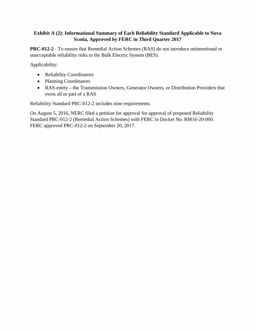
Exhibit A (2): Informational Summary of Each Reliability Standard Applicable to Nova Scotia, Approved by FERC in Third Quarter 2017
PRC-012-2 - To ensure that Remedial Action Schemes (RAS) do not introduce unintentional or unacceptable reliability risks to the Bulk Electric System (BES).
Applicability:
Reliability Coordinators Planning Coordinators RAS-entity – the Transmission Owners, Generator Owners, or Distribution Providers that
owns all or part of a RAS
Reliability Standard PRC-012-2 includes nine requirements.
On August 5, 2016, NERC filed a petition for approval for approval of proposed Reliability Standard PRC-012-2 (Remedial Action Schemes) with FERC in Docket No. RM16-20-000. FERC approved PRC-012-2 on September 20, 2017.

Exhibit A (2): Informational Summary of Each Reliability Standard Applicable to Nova Scotia, Approved by FERC in Third Quarter 2017
VAR-001-4.2 - To ensure that voltage levels, reactive flows, and reactive resources are monitored, controlled, and maintained within limits in Real-time to protect equipment and the reliable operation of the Interconnection.
Applicability:
Transmission Operators Generator Operators within the Western Interconnection (for the WECC Variance)
Reliability Standard VAR-001-4.2 includes six requirements.
On August 18, 2017, NERC filed a petition for approval of errata to proposed Reliability Standard VAR-001-4.2 (Voltage and Reactive Control) with FERC in Docket No. RD17-7-000. FERC approved VAR-001-4.2 on September 26, 2017.
Exhibit A (2): Informational Summary of Each Reliability Standard Applicable to Nova Scotia, Approved by FERC in Third Quarter 2017
VAR-002-4.1 - To ensure generators provide reactive support and voltage control, within generating Facility capabilities, in order to protect equipment and maintain reliable operation of the Interconnection.
Applicability:
Generator Operators Generator Owners
Reliability Standard VAR-002-4.1 includes six requirements.
On August 18, 2017, NERC filed a petition for approval of errata to proposed Reliability Standard VAR-002-4.1 (Generator Operation for Maintaining Network Voltage Schedules) with FERC in Docket No. RD17-7-000. FERC approved VAR-002-4.1 on September 26, 2017.

Exhibit A (3): Reliability Standards Filed for Approval

Reliability Standard BAL-005-1

BAL-005-1 – Balancing Authority Control
Page 1 of 11
A. Introduction
1. Title: Balancing Authority Control
2. Number: BAL-005-1
3. Purpose: This standard establishes requirements for acquiring data necessary to calculate Reporting Area Control Error (Reporting ACE). The standard also specifies a minimum periodicity, accuracy, and availability requirement for acquisition of the data and for providing the information to the System Operator.
4. Applicability:
4.1. Functional Entities:
4.1.1. Balancing Authority
Effective Date: See Implementation Plan for BAL-005-1
B. Requirements and Measures
R1. The Balancing Authority shall use a design scan rate of no more than six seconds in
acquiring data necessary to calculate Reporting ACE. [Violation Risk Factor: Medium] [Time Horizon: Real-time Operations]
M1. Each Balancing Authority will have dated documentation demonstrating that the data necessary to calculate Reporting ACE was designed to be scanned at a rate of no more than six seconds. Acceptable evidence may include historical data, dated archive files; or data from other databases, spreadsheets, or displays that demonstrate compliance.
R2. A Balancing Authority that is unable to calculate Reporting ACE for more than 30-consecutive minutes shall notify its Reliability Coordinator within 45 minutes of the beginning of the inability to calculate Reporting ACE. [Violation Risk Factor: Medium] [Time Horizon: Real-time Operations]
M2. Each Balancing Authority will have dated records to show when it was unable to calculate Reporting ACE for more than 30 consecutive minutes and that it notified its Reliability Coordinator within 45 minutes of the beginning of the inability to calculate Reporting ACE. Such evidence may include, but is not limited to, dated voice recordings, operating logs, or other communication documentation.
R3. Each Balancing Authority shall use frequency metering equipment for the calculation of Reporting ACE: [Violation Risk Factor: Medium] [Time Horizon: Real-time Operations]
3.1. that is available a minimum of 99.95% for each calendar year; and,
3.2. with a minimum accuracy of 0.001 Hz.
BAL-005-1 – Balancing Authority Control
Page 2 of 11
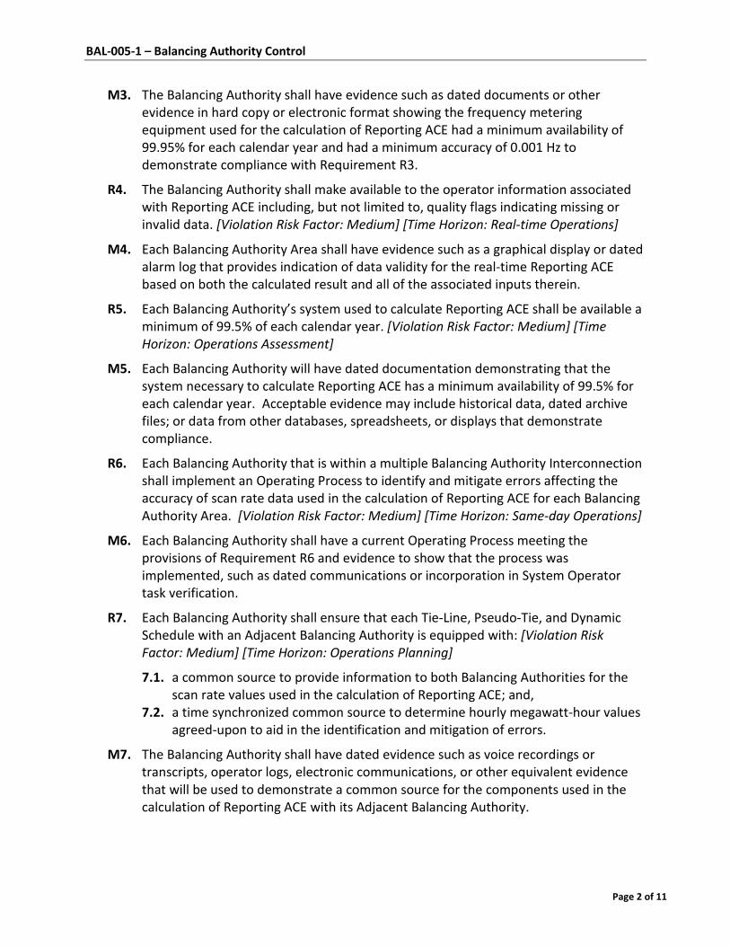
M3. The Balancing Authority shall have evidence such as dated documents or other evidence in hard copy or electronic format showing the frequency metering equipment used for the calculation of Reporting ACE had a minimum availability of 99.95% for each calendar year and had a minimum accuracy of 0.001 Hz to demonstrate compliance with Requirement R3.
R4. The Balancing Authority shall make available to the operator information associated with Reporting ACE including, but not limited to, quality flags indicating missing or invalid data. [Violation Risk Factor: Medium] [Time Horizon: Real-time Operations]
M4. Each Balancing Authority Area shall have evidence such as a graphical display or dated alarm log that provides indication of data validity for the real-time Reporting ACE based on both the calculated result and all of the associated inputs therein.
R5. Each Balancing Authority’s system used to calculate Reporting ACE shall be available a minimum of 99.5% of each calendar year. [Violation Risk Factor: Medium] [Time Horizon: Operations Assessment]
M5. Each Balancing Authority will have dated documentation demonstrating that the system necessary to calculate Reporting ACE has a minimum availability of 99.5% for each calendar year. Acceptable evidence may include historical data, dated archive files; or data from other databases, spreadsheets, or displays that demonstrate compliance.
R6. Each Balancing Authority that is within a multiple Balancing Authority Interconnection shall implement an Operating Process to identify and mitigate errors affecting the accuracy of scan rate data used in the calculation of Reporting ACE for each Balancing Authority Area. [Violation Risk Factor: Medium] [Time Horizon: Same-day Operations]
M6. Each Balancing Authority shall have a current Operating Process meeting the provisions of Requirement R6 and evidence to show that the process was implemented, such as dated communications or incorporation in System Operator task verification.
R7. Each Balancing Authority shall ensure that each Tie-Line, Pseudo-Tie, and Dynamic Schedule with an Adjacent Balancing Authority is equipped with: [Violation Risk Factor: Medium] [Time Horizon: Operations Planning]
7.1. a common source to provide information to both Balancing Authorities for the scan rate values used in the calculation of Reporting ACE; and,
7.2. a time synchronized common source to determine hourly megawatt-hour values agreed-upon to aid in the identification and mitigation of errors.
M7. The Balancing Authority shall have dated evidence such as voice recordings or transcripts, operator logs, electronic communications, or other equivalent evidence that will be used to demonstrate a common source for the components used in the calculation of Reporting ACE with its Adjacent Balancing Authority.
BAL-005-1 – Balancing Authority Control
Page 3 of 11
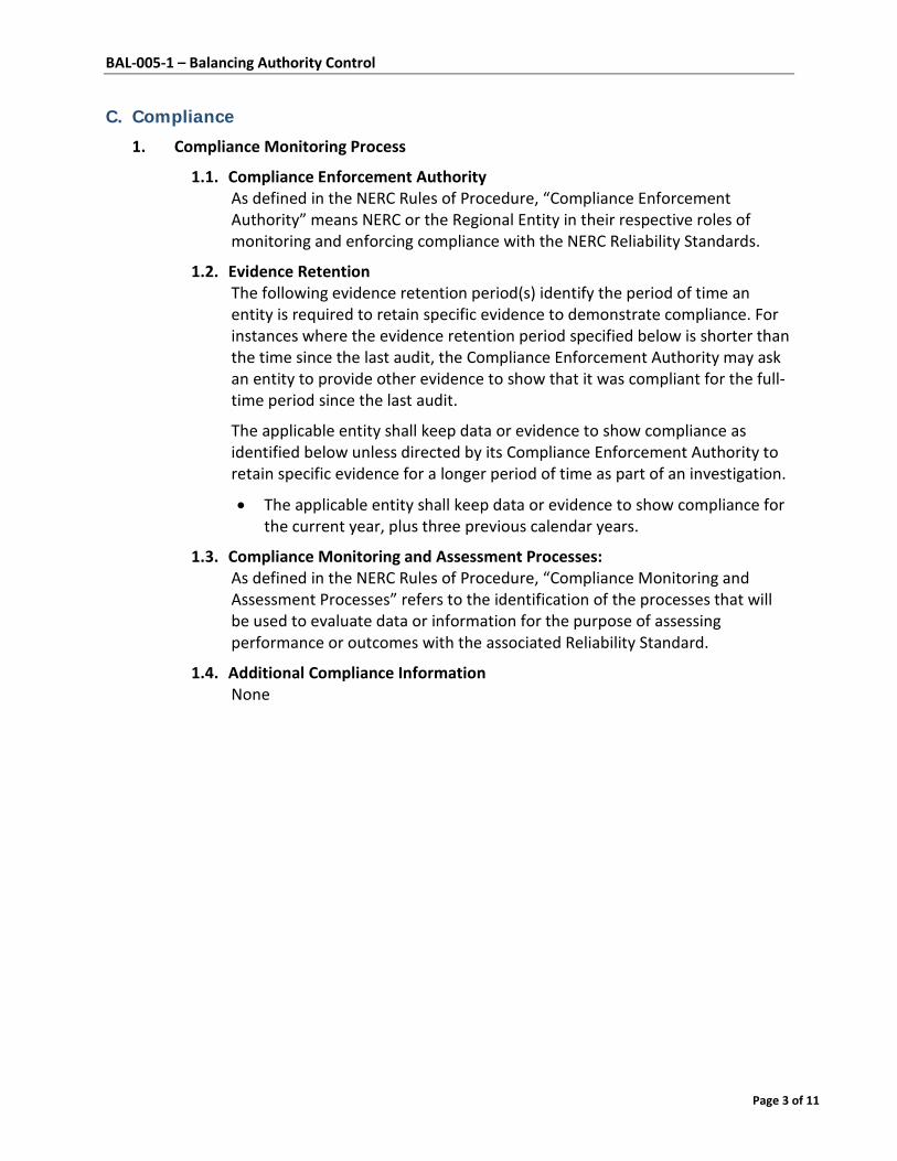
C. Compliance
1. Compliance Monitoring Process
1.1. Compliance Enforcement Authority As defined in the NERC Rules of Procedure, “Compliance Enforcement Authority” means NERC or the Regional Entity in their respective roles of monitoring and enforcing compliance with the NERC Reliability Standards.
1.2. Evidence Retention The following evidence retention period(s) identify the period of time an entity is required to retain specific evidence to demonstrate compliance. For instances where the evidence retention period specified below is shorter than the time since the last audit, the Compliance Enforcement Authority may ask an entity to provide other evidence to show that it was compliant for the full-time period since the last audit.
The applicable entity shall keep data or evidence to show compliance as identified below unless directed by its Compliance Enforcement Authority to retain specific evidence for a longer period of time as part of an investigation.
• The applicable entity shall keep data or evidence to show compliance for the current year, plus three previous calendar years.
1.3. Compliance Monitoring and Assessment Processes: As defined in the NERC Rules of Procedure, “Compliance Monitoring and Assessment Processes” refers to the identification of the processes that will be used to evaluate data or information for the purpose of assessing performance or outcomes with the associated Reliability Standard.
1.4. Additional Compliance Information None

BAL-005-1 – Balancing Authority Control
Page 4 of 11
Table of Compliance Elements
R # Time Horizon
VRF Violation Severity Levels
Lower VSL Moderate VSL High VSL Severe VSL
R1. Real-time Operations
Medium N/A N/A N/A Balancing Authority was using a design scan rate of greater than six seconds to acquire the data necessary to calculate Reporting ACE.
R2. Real-time Operations
Medium The Balancing Authority failed to notify its Reliability Coordinator within 45 minutes of the beginning of the inability to calculate Reporting ACE but notified its Reliability Coordinator in less than or equal to 50 minutes from the beginning of the
The Balancing Authority failed to notify its Reliability Coordinator within 50 minutes of the beginning of an inability to calculate Reporting ACE but notified its Reliability Coordinator in less than or equal to 55 minutes from the beginning of an
The Balancing Authority failed to notify its Reliability Coordinator within 55 minutes of the beginning of an inability to calculate Reporting ACE but notified its Reliability Coordinator in less than or equal to 60 minutes from the beginning of an
The Balancing Authority failed to notify its Reliability Coordinator within 60 minutes of the beginning of an inability to calculate Reporting ACE.

BAL-005-1 – Balancing Authority Control
Page 5 of 11
inability to calculate Reporting ACE.
inability to calculate Reporting ACE.
inability to calculate Reporting ACE.
R3. Real-time Operations
Medium The Balancing Authority’s frequency metering equipment used for the calculation of Reporting ACE was available less than 99.95% of the calendar year but was available greater than or equal to 99.94 % of the calendar year.
The Balancing Authority’s frequency metering equipment used for the calculation of Reporting ACE was available less than 99.94% of the calendar year but was available greater than or equal to 99.93 % of the calendar year.
The Balancing Authority’s frequency metering equipment used for the calculation of Reporting ACE was available less than 99.93% of the calendar year but was available greater than or equal to 99.92 % of the calendar year.
The Balancing Authority’s frequency metering equipment used for the calculation of Reporting ACE was available less than 99.92% of the calendar year
Or
The Balancing Authority’s frequency metering equipment used for the calculation of Reporting ACE failed to have a minimum accuracy of 0.001 Hz.
R4. Real-time Operations
Medium N/A N/A N/A The Balancing Authority failed to make available information indicating missing or invalid data associated with

BAL-005-1 – Balancing Authority Control
Page 6 of 11
Reporting ACE to its operators.
R5. Operations Assessment
Medium The Balancing Authority’s system used for the calculation of Reporting ACE was available less than 99.5% of the calendar year but was available greater than or equal to 99.4 % of the calendar year.
The Balancing Authority’s system used for the calculation of Reporting ACE was available less than 99.4% of the calendar year but was available greater than or equal to 99.3 % of the calendar year.
The Balancing Authority’s system used for the calculation of Reporting ACE was available less than 99.3% of the calendar year but was available greater than or equal to 99.2 % of the calendar year.
The Balancing Authority’s system used for the calculation of Reporting ACE was available less than 99.2% of the calendar year.
R6. Same-day Operations
Medium N/A N/A N/A The Balancing Authority failed to implement an Operating Process to identify and mitigate errors affecting the scan-rate accuracy of data used in the calculation of Reporting ACE.
R7. Operations Planning
Medium N/A N/A N/A The Balancing Authority failed to use a common source for Tie-Lines, Pseudo-ties and Dynamic

BAL-005-1 – Balancing Authority Control
Page 7 of 11
Schedules with its Adjacent Balancing Authorities
Or
The Balancing Authority failed to use a time synchronized common source for hourly megawatt hour values that are agreed-upon to aid in the identification and mitigation of errors.
D. Regional Variances
None.
E. Interpretations
None.
F. Associated Documents
None.

BAL-005-1 – Balancing Authority Control
Page 8 of 11
Version History
Version Date Action Change Tracking
0 February 8, 2005
Adopted by NERC Board of Trustees New
0 April 1, 2005 Effective Date New
0 August 8, 2005 Removed “Proposed” from Effective Date Errata
0a December 19, 2007
Added Appendix 1 – Interpretation of R17 approved by BOT on May 2, 2007
Addition
0a January 16, 2008
Section F: added “1.”; changed hyphen to “en dash.” Changed font style for “Appendix 1” to Arial
Errata
0b February 12, 2008
Replaced Appendix 1 – Interpretation of R17 approved by BOT on February 12, 2008 (BOT approved retirement of Interpretation included in BAL-005-0a)
Replacement
0.1b October 29, 2008
BOT approved errata changes; updated version number to “0.1b”
Errata
0.1b May 13, 2009 FERC approved – Updated Effective Date Addition
0.2b March 8, 2012 Errata adopted by Standards Committee; (replaced Appendix 1 with the FERC-approved revised interpretation of R17 and corrected standard version referenced in Interpretation by changing from “BAL-005-1” to “BAL-005-0)
Errata
0.2b September 13, 2012
FERC approved – Updated Effective Date Addition

BAL-005-1 – Balancing Authority Control
Page 9 of 11
0.2b February 7, 2013
R2 and associated elements approved by NERC Board of Trustees for retirement as part of the Paragraph 81 project (Project 2013-02) pending applicable regulatory approval.
0.2b November 21, 2013
R2 and associated elements approved by FERC for retirement as part of the Paragraph 81 project (Project 2013-02) effective January 21, 2014.
1 February 11, 2016
Adopted by NERC Board of Trustees Complete re-write of standard
1 September 20. 2017
FERC Order No. 836 approved BAL-005-1.

Supplemental Material
Page 10 of 11
Rationale
During development of this standard, text boxes were embedded within the standard to explain the rationale for various parts of the standard. Upon Board approval, the text from the rationale boxes will be moved to this section. Rationale for Requirement R1: Real-time operation of a Balancing Authority requires real-time information. A sufficient scan rate is key to an Operator’s trust in real-time information. Without a sufficient scan rate, an operator may question the accuracy of data during events, which would degrade the operator’s ability to maintain reliability. Rationale for Requirement R2: The RC is responsible for coordinating the reliability of bulk electric systems for member BA’s. When a BA is unable to calculate its ACE for an extended period of time, this information must be communicated to the RC within 15 minutes thereafter so that the RC has sufficient knowledge of system conditions to assess any unintended reliability consequences that may occur on the wide area. Rationale for Requirement R3: Frequency is the basic measurement for interconnection health, and a critical component for calculating Reporting ACE. Without sufficient available frequency data the BA operator will lack situational awareness and will be unable to make correct decisions when maintaining reliability. Rationale for Requirement R4: System operators utilize Reporting ACE as a primary metric to determine operating actions or instructions. When data inputs into the ACE calculation are incorrect, the operator should be made aware through visual display. When an operator questions the validity of data, actions are delayed and the probability of adverse events occurring can increase. Rationale for Requirement R5: Reporting ACE is an essential measurement of the BA’s contribution to the reliability of the Interconnection. Since Reporting ACE is a measure of the BA’s reliability performance for BAL-001, and BAL-002, it is critical that Reporting ACE be sufficiently available to assure reliability. Rationale for Requirement R6: Reporting ACE is a measure of the BA’s reliability performance for BAL-001, and BAL-002. Without a process to address persistent errors in the ACE calculation, the operator can lose trust in the validity of Reporting ACE resulting in delayed or incorrect decisions regarding the reliability of the bulk electric system. Rationale for Requirement R7: Reporting ACE is an essential measurement of the BA’s contribution to the reliability of the Interconnection. Common source data is critical to calculating Reporting ACE that is consistent between Balancing Authorities. When data sources are not common, confusion can be created between BAs resulting in delayed or incorrect operator action.

Supplemental Material
Page 11 of 11
The intent of Requirement R7 Part 7.1 is to provide accuracy in the measurement and calculations used in Reporting ACE. It specifies the need for common metering points for instantaneous values for the tie-line megawatt flow values between Balancing Authority Areas. Common data source requirements also apply to instantaneous values for pseudo-ties and dynamic schedules, and can extend to more than two Balancing Authorities that participate in allocating shares of a generation resource in supplementary regulation, for example.
The intent of Requirement R7 Part 7.2 is to enable accuracy in the measurements and calculations used in Reporting ACE. It specifies the need for common metering points for hourly accumulated values for the time synchronized tie line MWh values agreed-upon between Balancing Authority Areas. These time synchronized agreed-upon values are necessary for use in the Operating Process required in R6 to identify and mitigate errors in the scan-rate values used in Reporting ACE.
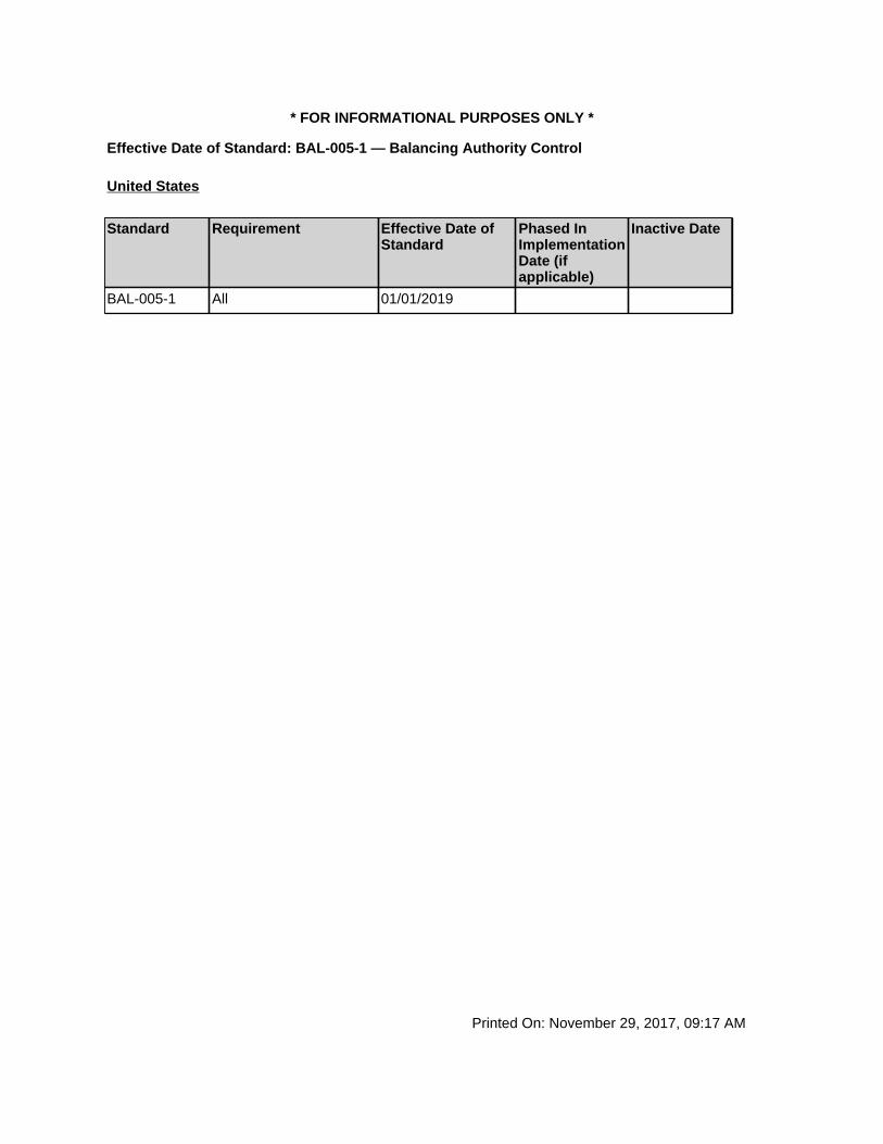
Standard Requirement Effective Date of Standard
Phased In Implementation Date (if applicable)
Inactive Date
BAL-005-1 All 01/01/2019
Printed On: November 29, 2017, 09:17 AM
Effective Date of Standard: BAL-005-1 — Balancing Authority Control
* FOR INFORMATIONAL PURPOSES ONLY *
United States

Reliability Standard FAC-001-3

FAC-001-3 — Facility Interconnection Requirements
Page 1 of 9
A. Introduction
1. Title: Facility Interconnection Requirements
2. Number: FAC-001-3
3. Purpose: To avoid adverse impacts on the reliability of the Bulk Electric System, Transmission Owners and applicable Generator Owners must document and make Facility interconnection requirements available so that entities seeking to interconnect will have the necessary information.
4. Applicability:
4.1. Functional Entities: 4.1.1 Transmission Owner
4.1.2 Applicable Generator Owner
4.1.2.1 Generator Owner with a fully executed Agreement to conduct a study on the reliability impact of interconnecting a third party Facility to the Generator Owner’s existing Facility that is used to interconnect to the Transmission system.
5. Effective Date: See Implementation Plan for FAC-001-3.
B. Requirements and Measures
R1. Each Transmission Owner shall document Facility interconnection requirements, update them as needed, and make them available upon request. Each Transmission Owner’s Facility interconnection requirements shall address interconnection requirements for: [Violation Risk Factor: Lower] [Time Horizon: Long-term Planning]
1.1. generation Facilities;
1.2. transmission Facilities; and
1.3. end-user Facilities.
M1. Each Transmission Owner shall have evidence (such as dated, documented Facility interconnection requirements) that it met all requirements in Requirement R1.
R2. Each applicable Generator Owner shall document Facility interconnection requirements and make them available upon request within 45 calendar days of full execution of an Agreement to conduct a study on the reliability impact of interconnecting a third party Facility to the Generator Owner’s existing Facility that is used to interconnect to the Transmission system. [Violation Risk Factor: Lower] [Time Horizon: Long-term Planning]
M2. Each applicable Generator Owner shall have evidence (such as dated, documented Facility interconnection requirements) that it met all requirements in Requirement R2.

FAC-001-3 — Facility Interconnection Requirements
Page 2 of 9
R3. Each Transmission Owner shall address the following items in its Facility interconnection requirements: [Violation Risk Factor: Lower] [Time Horizon: Long-Term Planning]
3.1. Procedures for coordinated studies of new or materially modified existing interconnections and their impacts on affected system(s).
3.2. Procedures for notifying those responsible for the reliability of affected system(s) of new or materially modified existing interconnections.
3.3. Procedures for confirming with those responsible for the reliability of affected systems of new or materially modified transmission Facilities are within a Balancing Authority Area’s metered boundaries.
M3. Each Transmission Owner shall have evidence (such as dated, documented Facility interconnection requirements addressing the procedures) that it met all requirements in Requirement R3.
R4. Each applicable Generator Owner shall address the following items in its Facility interconnection requirements: [Violation Risk Factor: Lower] [Time Horizon: Long-Term Planning]
4.1. Procedures for coordinated studies of new interconnections and their impacts on affected system(s).
4.2. Procedures for notifying those responsible for the reliability of affected system(s) of new interconnections.
4.3. Procedures for confirming with those responsible for the reliability of affected systems of new or materially modified generation Facilities are within a Balancing Authority Area’s metered boundaries.
M4. Each applicable Generator Owner shall have evidence (such as dated, documented Facility interconnection requirements addressing the procedures) that it met all requirements in Requirement R4.
C. Compliance
1. Compliance Monitoring Process
1.1. Compliance Enforcement Authority
As defined in the NERC Rules of Procedure, “Compliance Enforcement Authority” (CEA) means NERC or the Regional Entity in their respective roles of monitoring and enforcing compliance with the NERC Reliability Standards.
1.2. Evidence Retention
The following evidence retention periods identify the period of time an entity is required to retain specific evidence to demonstrate compliance. For instances where the evidence retention period specified below is shorter than the time since the last audit, the CEA may ask an entity to provide other evidence to show that it was compliant for the full time period since the last audit.

FAC-001-3 — Facility Interconnection Requirements
Page 3 of 9
The applicable Functional Entity shall keep data or evidence to show compliance as identified below unless directed by its CEA to retain specific evidence for a longer period of time as part of an investigation:
The responsible entities shall retain documentation as evidence for three years.
If a responsible entity is found non-compliant, it shall keep information related to the non-compliance until mitigation is complete and approved or for the time specified above, whichever is longer.
The CEA shall keep the last audit records and all requested and submitted subsequent audit records.
1.3. Compliance Monitoring and Assessment Processes:
Compliance Audit
Self-Certification
Spot Check
Compliance Investigation
Self-Reporting
Complaint
1.4. Additional Compliance Information
None

FAC-001-3 — Facility Interconnection Requirements
Page 4 of 9
Table of Compliance Elements
R # Time Horizon
VRF Violation Severity Levels
Lower VSL Moderate VSL High VSL Severe VSL
R1 Long-term Planning
Lower N/A The Transmission Owner documented Facility interconnection requirements and updated them as needed, but failed to make them available upon request.
OR
The Transmission Owner documented Facility interconnection requirements and made them available upon request, but failed to update them as needed.
OR
The Transmission Owner documented Facility interconnection requirements, updated them as needed, and made them available upon request, but
The Transmission Owner documented Facility interconnection requirements, but failed to update them as needed and failed to make them available upon request.
OR
The Transmission Owner documented Facility interconnection requirements, updated them as needed, and made them available upon request, but failed to address interconnection requirements for two of the Facilities as specified in R1, Parts 1.1, 1.2, or 1.3.
The Transmission Owner did not document Facility interconnection requirements.

FAC-001-3 — Facility Interconnection Requirements
Page 5 of 9
failed to address interconnection requirements for one of the Facilities as specified in R1, Parts 1.1, 1.2, or 1.3.
R2 Long-term Planning
Lower The applicable Generator Owner failed to document Facility interconnection requirements and make them available upon request until more than 45 calendar days but less than or equal to 60 calendar days after full execution of an Agreement to conduct a study on the reliability impact of interconnecting a third party Facility to the Generator Owner’s existing Facility that is used to interconnect to the Transmission system.
The applicable Generator Owner failed to document Facility interconnection requirements and make them available upon request until more than 60 calendar days but less than or equal to 70 calendar days after full execution of an Agreement to conduct a study on the reliability impact of interconnecting a third party Facility to the Generator Owner’s existing Facility that is used to interconnect to the Transmission system.
The applicable Generator Owner failed to document Facility interconnection requirements and make them available upon request until more than 70 calendar days but less than or equal to 80 calendar days after full execution of an Agreement to conduct a study on the reliability impact of interconnecting a third party Facility to the Generator Owner’s existing Facility that is used to interconnect to the Transmission system.
The applicable Generator Owner failed to document Facility interconnection requirements and make them available upon request until more than 80 calendar days after full execution of an Agreement to conduct a study on the reliability impact of interconnecting a third party Facility to the Generator Owner’s existing Facility that is used to interconnect to the Transmission system.

FAC-001-3 — Facility Interconnection Requirements
Page 6 of 9
R3 Long-term Planning
Lower N/A The Transmission Owner failed to address one part of Requirement R3 Part 3.1 through Part 3.3.
The Transmission Owner failed to address two parts of Requirement R3 Part 3.1 through Part 3.3.
The Transmission Owner failed to address Requirement R3 Part 3.1 through Part 3.3.
R4 Long-term Planning
Lower N/A The Generator Owner failed to address one part of Requirement R4 Part 4.1 through Part 4.3.
The Generator Owner failed to address two parts of Requirement R4 Part 4.1 through Part 4.3.
The Generator Owner failed to address Requirement R4 Part 4.1 through Part 4.3.
D. Regional Variances
None.
E. Interpretations
None.
F. Associated Documents
None.

FAC-001-3 — Facility Interconnection Requirements
Page 7 of 9
Version History
Version Date Action Change Tracking
0 April 1, 2005 Effective Date New
1 Added requirements for Generator Owner and brought overall standard format up to date.
Revision under Project 2010-07
1 February 9, 2012 Adopted by the Board of Trustees
1 September 19, 2013 A FERC order was issued on September 19, 2013, approving FAC-001-1. This standard became enforceable on November 25, 2013 for Transmission Owners. For Generator Owners, the standard becomes enforceable on January 1, 2015.
2 Revisions to implement the recommendations of the FAC Five-Year Review Team.
Revision under Project 2010-02
2 August 14, 2014 Adopted by the Board of Trustees
2 November 6, 2014 FERC letter order issued approving FAC-001-2.
3 February 11, 2016 Adopted by the Board of Trustees Moved BAL-005-0.2b Requirement R1 into FAC-001-3 Requirements R3 and R4
3 September 20, 2017 FERC Order No. 836 issued approving FAC-001-3

Supplemental Material
Page 8 of 9
Guidelines and Technical Basis
Entities should have documentation to support the technical rationale for determining whether an existing interconnection was “materially modified.” Recognizing that what constitutes a “material modification” will vary from entity to entity, the intent is for this determination to be based on engineering judgment.
Requirement R3:
Originally the Parts of R3, with the exception of the first two bullets, which were added by the Project 2010-02 drafting team, this list has been moved to the Guidelines and Technical Basis section to provide entities with the flexibility to determine the Facility interconnection requirements that are technically appropriate for their respective Facilities. Including them as Parts of R3 was deemed too prescriptive, as frequently some items in the list do not apply to all applicable entities – and some applicable entities will have requirements that are not included in this list.
Each Transmission Owner and applicable Generator Owner should consider the following items in the development of Facility interconnection requirements:
• Procedures for requesting a new Facility interconnection or material modification to an existing interconnection
• Data required to properly study the interconnection
• Voltage level and MW and MVAR capacity or demand at the point of interconnection
• Breaker duty and surge protection
• System protection and coordination
• Metering and telecommunications
• Grounding and safety issues
• Insulation and insulation coordination
• Voltage, Reactive Power (including specifications for minimum static and dynamic reactive power requirements), and power factor control
• Power quality impacts
• Equipment ratings
• Synchronizing of Facilities
• Maintenance coordination
• Operational issues (abnormal frequency and voltages)
• Inspection requirements for new or materially modified existing interconnections
• Communications and procedures during normal and emergency operating conditions

Supplemental Material
Page 9 of 9
Rationale
During development of this standard, text boxes were embedded within the standard to explain the rationale for various parts of the standard. Upon Board approval, the text from the rationale boxes will be moved to this section. Rationale for Requirement R3.3: Consistent with the Functional Model, there cannot be an assumption that the entity owning the transmission will be the same entity providing the BA function. It is the responsibility of the party interconnecting to make appropriate arrangements with a Balancing Authority to ensure its Facilities are within the BA’s metered boundaries, which also serves to facilitate the process of the coordination between the two entities that will be required under numerous other standards upon the start of operation. Under 3.3, the Transmission Owner is responsible for confirming that the party interconnecting has made appropriate provisions with a Balancing Authority to operate within its metered boundaries. Rationale for Requirement R4.3: Consistent with the Functional Model, there cannot be an assumption that the entity owning the generation will be the same entity providing the BA function. It is the responsibility of the party interconnecting to make appropriate arrangements with a Balancing Authority to ensure its Facilities are within the BA’s metered boundaries, which also serves to facilitate the process of the coordination between the two entities that will be required under numerous other standards upon the start of operation. Under 4.3, the Generator Owner is responsible for confirming that the party interconnecting has made appropriate provisions with a Balancing Authority to operate within its metered boundaries.
Standard Requirement Effective Date of Standard
Phased In Implementation Date (if applicable)
Inactive Date
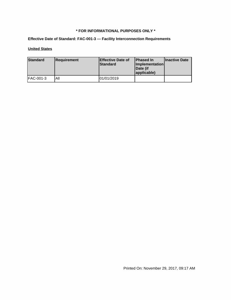
FAC-001-3 All 01/01/2019
Printed On: November 29, 2017, 09:17 AM
Effective Date of Standard: FAC-001-3 — Facility Interconnection Requirements
* FOR INFORMATIONAL PURPOSES ONLY *
United States

Reliability Standard PRC-012-2
PRC-012-2 – Remedial Action Schemes
Page 1 of 49
A. Introduction
1. Title: Remedial Action Schemes
2. Number: PRC-012-2
3. Purpose: To ensure that Remedial Action Schemes (RAS) do not introduce unintentional or unacceptable reliability risks to the Bulk Electric System (BES).
4. Applicability:
4.1. Functional Entities:
4.1.1. Reliability Coordinator
4.1.2. Planning Coordinator
4.1.3. RAS-entity – the Transmission Owner, Generator Owner, or Distribution Provider that owns all or part of a RAS
4.2. Facilities:
4.2.1. Remedial Action Schemes (RAS)
5. Effective Date: See the Implementation Plan for PRC-012-2. B. Requirements and Measures
R1. Prior to placing a new or functionally modified RAS in service or retiring an existing RAS, each RAS-entity shall provide the information identified in Attachment 1 for review to the Reliability Coordinator(s) where the RAS is located. [Violation Risk Factor: Medium] [Time Horizon: Operations Planning]
M1. Acceptable evidence may include, but is not limited to, a copy of the Attachment 1 documentation and the dated communications with the reviewing Reliability Coordinator(s) in accordance with Requirement R1.
R2. Each Reliability Coordinator that receives Attachment 1 information pursuant to Requirement R1 shall, within four full calendar months of receipt or on a mutually agreed upon schedule, perform a review of the RAS in accordance with Attachment 2, and provide written feedback to each RAS-entity. [Violation Risk Factor: Medium] [Time Horizon: Operations Planning]
M2. Acceptable evidence may include, but is not limited to, dated reports, checklists, or other documentation detailing the RAS review, and the dated communications with the RAS-entity in accordance with Requirement R2.
R3. Prior to placing a new or functionally modified RAS in service or retiring an existing RAS, each RAS-entity that receives feedback from the reviewing Reliability Coordinator(s) identifying reliability issue(s) shall resolve each issue to obtain approval of the RAS from each reviewing Reliability Coordinator. [Violation Risk Factor: Medium] [Time Horizon: Operations Planning]

PRC-012-2 – Remedial Action Schemes
Page 2 of 49
M3. Acceptable evidence may include, but is not limited to, dated documentation and communications with the reviewing Reliability Coordinator that no reliability issues were identified during the review or that all identified reliability issues were resolved in accordance with Requirement R3.
R4. Each Planning Coordinator, at least once every five full calendar years, shall: [Violation Risk Factor: Medium] [Time Horizon: Long-term Planning]
4.1. Perform an evaluation of each RAS within its planning area to determine whether:
4.1.1. The RAS mitigates the System condition(s) or Contingency(ies) for which it was designed.
4.1.2. The RAS avoids adverse interactions with other RAS, and protection and control systems.
4.1.3. For limited impact1 RAS, the inadvertent operation of the RAS or the failure of the RAS to operate does not cause or contribute to BES Cascading, uncontrolled separation, angular instability, voltage instability, voltage collapse, or unacceptably damped oscillations.
4.1.4. Except for limited impact RAS, the possible inadvertent operation of the RAS, resulting from any single RAS component malfunction satisfies all of the following:
4.1.4.1. The BES shall remain stable.
4.1.4.2. Cascading shall not occur.
4.1.4.3. Applicable Facility Ratings shall not be exceeded.
4.1.4.4. BES voltages shall be within post-Contingency voltage limits and post-Contingency voltage deviation limits as established by the Transmission Planner and the Planning Coordinator.
4.1.4.5. Transient voltage responses shall be within acceptable limits as established by the Transmission Planner and the Planning Coordinator.
4.1.5. Except for limited impact RAS, a single component failure in the RAS, when the RAS is intended to operate does not prevent the BES from meeting the same performance requirements (defined in Reliability Standard TPL-001-4 or its successor) as those required for the events and conditions for which the RAS is designed.
1 A RAS designated as limited impact cannot, by inadvertent operation or failure to operate, cause or contribute to BES Cascading, uncontrolled separation, angular instability, voltage instability, voltage collapse, or unacceptably damped oscillations.

PRC-012-2 – Remedial Action Schemes
Page 3 of 49
4.2. Provide the results of the RAS evaluation including any identified deficiencies to each reviewing Reliability Coordinator and RAS-entity, and each impacted Transmission Planner and Planning Coordinator.
M4. Acceptable evidence may include, but is not limited to, dated reports or other documentation of the analyses comprising the evaluation(s) of each RAS and dated communications with the RAS-entity(ies), Transmission Planner(s), Planning Coordinator(s), and the reviewing Reliability Coordinator(s) in accordance with Requirement R4.
R5. Each RAS-entity, within 120 full calendar days of a RAS operation or a failure of its RAS to operate when expected, or on a mutually agreed upon schedule with its reviewing Reliability Coordinator(s), shall: [Violation Risk Factor: Medium] [Time Horizon: Operations Planning]
5.1. Participate in analyzing the RAS operational performance to determine whether:
5.1.1. The System events and/or conditions appropriately triggered the RAS.
5.1.2. The RAS responded as designed.
5.1.3. The RAS was effective in mitigating BES performance issues it was designed to address.
5.1.4. The RAS operation resulted in any unintended or adverse BES response.
5.2. Provide the results of RAS operational performance analysis that identified any deficiencies to its reviewing Reliability Coordinator(s).
M5. Acceptable evidence may include, but is not limited to, dated documentation detailing the results of the RAS operational performance analysis and dated communications with participating RAS-entities and the reviewing Reliability Coordinator(s) in accordance with Requirement R5.
R6. Each RAS-entity shall participate in developing a Corrective Action Plan (CAP) and submit the CAP to its reviewing Reliability Coordinator(s) within six full calendar months of: [Violation Risk Factor: Medium] [Time Horizon: Operations Planning, Long-term Planning]
• Being notified of a deficiency in its RAS pursuant to Requirement R4, or
• Notifying the Reliability Coordinator of a deficiency pursuant to Requirement R5, Part 5.2, or
• Identifying a deficiency in its RAS pursuant to Requirement R8.
M6. Acceptable evidence may include, but is not limited to, a dated CAP and dated communications among each reviewing Reliability Coordinator and each RAS-entity in accordance with Requirement R6.

PRC-012-2 – Remedial Action Schemes
Page 4 of 49
R7. Each RAS-entity shall, for each of its CAPs developed pursuant to Requirement R6: [Violation Risk Factor: Medium] [Time Horizon: Operations Planning, Long-term Planning]
7.1. Implement the CAP.
7.2. Update the CAP if actions or timetables change.
7.3. Notify each reviewing Reliability Coordinator if CAP actions or timetables change and when the CAP is completed.
M7. Acceptable evidence may include, but is not limited to, dated documentation such as CAPs, project or work management program records, settings sheets, work orders, maintenance records, and communication with the reviewing Reliability Coordinator(s) that documents the implementation, updating, or completion of a CAP in accordance with Requirement R7.
R8. Each RAS-entity shall participate in performing a functional test of each of its RAS to verify the overall RAS performance and the proper operation of non-Protection System components: [Violation Risk Factor: High] [Time Horizon: Long-term Planning]
• At least once every six full calendar years for all RAS not designated as limited impact, or
• At least once every twelve full calendar years for all RAS designated as limited impact
M8. Acceptable evidence may include, but is not limited to, dated documentation detailing the RAS operational performance analysis for a correct RAS segment or an end-to-end operation (Measure M5 documentation), or dated documentation demonstrating that a functional test of each RAS segment or an end-to-end test was performed in accordance with Requirement R8.
R9. Each Reliability Coordinator shall update a RAS database containing, at a minimum, the information in Attachment 3 at least once every twelve full calendar months. [Violation Risk Factor: Lower] [Time Horizon: Operations Planning]
M9. Acceptable evidence may include, but is not limited to, dated spreadsheets, database reports, or other documentation demonstrating a RAS database was updated in accordance with Requirement R9.
C. Compliance
1. Compliance Monitoring Process
1.1. Compliance Enforcement Authority: As defined in the NERC Rules of Procedure, “Compliance Enforcement Authority” means NERC or the Regional Entity in their respective roles of monitoring and enforcing compliance with the NERC Reliability Standards.
1.2. Evidence Retention:

PRC-012-2 – Remedial Action Schemes
Page 5 of 49
The following evidence retention period(s) identify the period of time an entity is required to retain specific evidence to demonstrate compliance. For instances where the evidence retention period specified below is shorter than the time since the last audit, the Compliance Enforcement Authority may ask an entity to provide other evidence to show that it was compliant for the full-time period since the last audit.
The applicable entity shall keep data or evidence to show compliance as identified below unless directed by its Compliance Enforcement Authority to retain specific evidence for a longer period of time as part of an investigation.
The RAS-entity (Transmission Owner, Generator Owner, and Distribution Provider) shall each keep data or evidence to show compliance with Requirements R1, R3, R5, R6, R7, and R8, and Measures M1, M3, M5, M6, M7, and M8 since the last audit, unless directed by its Compliance Enforcement Authority to retain specific evidence for a longer period of time as part of an investigation.
The Reliability Coordinator shall each keep data or evidence to show compliance with Requirements R2 and R9, and Measures M2 and M9 since the last audit, unless directed by its Compliance Enforcement Authority to retain specific evidence for a longer period of time as part of an investigation.
The Planning Coordinator shall each keep data or evidence to show compliance with Requirement R4 and Measure M4 since the last audit, unless directed by its Compliance Enforcement Authority to retain specific evidence for a longer period of time as part of an investigation.
If a RAS-entity (Transmission Owner, Generator Owner or Distribution Provider), Reliability Coordinator, or Planning Coordinator is found non-compliant, it shall keep information related to the non-compliance until mitigation is completed and approved, or for the time specified above, whichever is longer.
The Compliance Enforcement Authority shall keep the last audit records and all requested and submitted subsequent audit records.
1.3. Compliance Monitoring and Enforcement Program As defined in the NERC Rules of Procedure, “Compliance Monitoring and Enforcement Program” refers to the identification of the processes that will be used to evaluate data or information for the purpose of assessing performance or outcomes with the associated Reliability Standard.

PRC-012-2 – Remedial Action Schemes
Page 6 of 49
Violation Severity Levels
R # Violation Severity Levels
Lower VSL Moderate VSL High VSL Severe VSL
R1. N/A N/A N/A The RAS-entity failed to provide the information identified in Attachment 1 to each Reliability Coordinator prior to placing a new or functionally modified RAS in service or retiring an existing RAS in accordance with Requirement R1.
R2. The reviewing Reliability Coordinator performed the review and provided the written feedback in accordance with Requirement R2, but was late by less than or equal to 30 full calendar days.
The reviewing Reliability Coordinator performed the review and provided the written feedback in accordance with Requirement R2, but was late by more than 30 full calendar days but less than or equal to 60 full calendar days.
The reviewing Reliability Coordinator performed the review and provided the written feedback in accordance with Requirement R2, but was late by more than 60 full calendar days but less than or equal to 90 full calendar days.
The reviewing Reliability Coordinator performed the review and provided the written feedback in accordance with Requirement R2, but was late by more than 90 full calendar days.
OR
The reviewing Reliability Coordinator failed to perform the review or provide feedback in accordance with Requirement R2.

PRC-012-2 – Remedial Action Schemes
Page 7 of 49
R # Violation Severity Levels
Lower VSL Moderate VSL High VSL Severe VSL
R3. N/A N/A N/A The RAS-entity failed to resolve identified reliability issue(s) to obtain approval from each reviewing Reliability Coordinator prior to placing a new or functionally modified RAS in service or retiring an existing RAS in accordance with Requirement R3.
R4. The Planning Coordinator performed the evaluation in accordance with Requirement R4, but was late by less than or equal to 30 full calendar days.
The Planning Coordinator performed the evaluation in accordance with Requirement R4, but was late by more than 30 full calendar days but less than or equal to 60 full calendar days.
The Planning Coordinator performed the evaluation in accordance with Requirement R4, but was late by more than 60 full calendar days but less than or equal to 90 full calendar days.
OR
The Planning Coordinator performed the evaluation in accordance with Requirement R4, but failed to evaluate one of the Parts 4.1.1 through 4.1.5.
The Planning Coordinator performed the evaluation in accordance with Requirement R4, but was late by more than 90 full calendar days.
OR
The Planning Coordinator performed the evaluation in accordance with Requirement R4, but failed to evaluate two or more of the Parts 4.1.1 through 4.1.5.
OR

PRC-012-2 – Remedial Action Schemes
Page 8 of 49
R # Violation Severity Levels
Lower VSL Moderate VSL High VSL Severe VSL
The Planning Coordinator performed the evaluation in accordance with Requirement R4, but failed to provide the results to one or more of the receiving entities listed in Part 4.2.
OR
The Planning Coordinator failed to perform the evaluation in accordance with Requirement R4.
R5. The RAS-entity performed the analysis in accordance with Requirement R5, but was late by less than or equal to 10 full calendar days.
The RAS-entity performed the analysis in accordance with Requirement R5, but was late by more than 10 full calendar days but less than or equal to 20 full calendar days.
The RAS-entity performed the analysis in accordance with Requirement R5, but was late by more than 20 full calendar days but less than or equal to 30 full calendar days.
OR
The RAS-entity performed the analysis in accordance with Requirement R5, but failed to address one of the Parts 5.1.1 through 5.1.4.
The RAS-entity performed the analysis in accordance with Requirement R5, but was late by more than 30 full calendar days.
OR
The RAS-entity performed the analysis in accordance with Requirement R5, but failed to address two or more of the Parts 5.1.1 through 5.1.4.
PRC-012-2 – Remedial Action Schemes
Page 9 of 49
R # Violation Severity Levels
Lower VSL Moderate VSL High VSL Severe VSL
OR
The RAS-entity performed the analysis in accordance with Requirement R5, but failed to provide the results (Part 5.2) to one or more of the reviewing Reliability Coordinator(s).
OR
The RAS-entity failed to perform the analysis in accordance with Requirement R5.
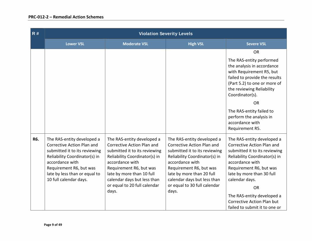
R6. The RAS-entity developed a Corrective Action Plan and submitted it to its reviewing Reliability Coordinator(s) in accordance with Requirement R6, but was late by less than or equal to 10 full calendar days.
The RAS-entity developed a Corrective Action Plan and submitted it to its reviewing Reliability Coordinator(s) in accordance with Requirement R6, but was late by more than 10 full calendar days but less than or equal to 20 full calendar days.
The RAS-entity developed a Corrective Action Plan and submitted it to its reviewing Reliability Coordinator(s) in accordance with Requirement R6, but was late by more than 20 full calendar days but less than or equal to 30 full calendar days.
The RAS-entity developed a Corrective Action Plan and submitted it to its reviewing Reliability Coordinator(s) in accordance with Requirement R6, but was late by more than 30 full calendar days.
OR
The RAS-entity developed a Corrective Action Plan but failed to submit it to one or

PRC-012-2 – Remedial Action Schemes
Page 10 of 49
R # Violation Severity Levels
Lower VSL Moderate VSL High VSL Severe VSL
more of its reviewing Reliability Coordinator(s) in accordance with Requirement R6.
OR
The RAS-entity failed to develop a Corrective Action Plan in accordance with Requirement R6.
R7. The RAS-entity implemented a CAP in accordance with Requirement R7, Part 7.1, but failed to update the CAP (Part 7.2) if actions or timetables changed, or failed to notify (Part 7.3) each of the reviewing Reliability Coordinator(s) of the updated CAP or completion of the CAP.
N/A N/A The RAS-entity failed to implement a CAP in accordance with Requirement R7, Part 7.1.
R8. The RAS-entity performed the functional test for a RAS as specified in Requirement R8, but was late by less than
The RAS-entity performed the functional test for a RAS as specified in Requirement R8, but was late by more than 30 full calendar days
The RAS-entity performed the functional test for a RAS as specified in Requirement R8, but was late by more than 60 full calendar days
The RAS-entity performed the functional test for a RAS as specified in Requirement R8, but was late by more than 90 full calendar days.

PRC-012-2 – Remedial Action Schemes
Page 11 of 49
R # Violation Severity Levels
Lower VSL Moderate VSL High VSL Severe VSL
or equal to 30 full calendar days.
but less than or equal to 60 full calendar days.
but less than or equal to 90 full calendar days.
OR
The RAS-entity failed to perform the functional test for a RAS as specified in Requirement R8.
R9. The Reliability Coordinator updated the RAS database in accordance with Requirement R9, but was late by less than or equal to 30 full calendar days.
The Reliability Coordinator updated the RAS database in accordance with Requirement R9, but was late by more than 30 full calendar days but less than or equal to 60 full calendar days.
The Reliability Coordinator updated the RAS database in accordance with Requirement R9, but was late by more than 60 full calendar days but less than or equal to 90 full calendar days.
The Reliability Coordinator updated the RAS database in accordance with Requirement R9 but was late by more than 90 full calendar days.
OR The Reliability Coordinator failed to update the RAS database in accordance with Requirement R9.
PRC-012-2 – Remedial Action Schemes
Page 12 of 49
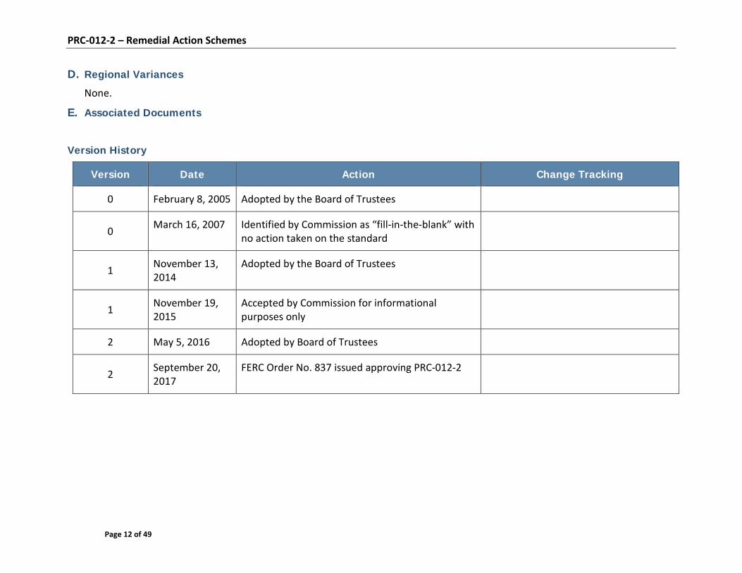
D. Regional Variances
None.
E. Associated Documents
Version History
Version Date Action Change Tracking
0 February 8, 2005 Adopted by the Board of Trustees
0 March 16, 2007 Identified by Commission as “fill-in-the-blank” with
no action taken on the standard
1 November 13, 2014
Adopted by the Board of Trustees
1 November 19, 2015
Accepted by Commission for informational purposes only
2 May 5, 2016 Adopted by Board of Trustees
2 September 20, 2017
FERC Order No. 837 issued approving PRC-012-2

Attachments
Page 13 of 49
Attachment 1 Supporting Documentation for RAS Review
The following checklist identifies important Remedial Action Scheme (RAS) information for each new or functionally modified2 RAS that the RAS-entity must document and provide to the reviewing Reliability Coordinator(s) (RC). If an item on this list does not apply to a specific RAS, a response of “Not Applicable” for that item is appropriate. When RAS are submitted for functional modification review and approval, only the proposed modifications to that RAS require review; however, the RAS-entity must provide a summary of the existing functionality. The RC may request additional information on any aspect of the RAS as well as any reliability issue related to the RAS. Additional entities (without decision authority) may be part of the RAS review process at the request of the RC.
I. General
1. Information such as maps, one-line drawings, substation and schematic drawings that identify the physical and electrical location of the RAS and related facilities.
2. Functionality of new RAS or proposed functional modifications to existing RAS and documentation of the pre- and post-modified functionality of the RAS.
3. The Corrective Action Plan (CAP) if RAS modifications are proposed in a CAP.
4. Data to populate the RAS database:
a. RAS name.
b. Each RAS-entity and contact information.
c. Expected or actual in-service date; most recent RC-approval date (Requirement R3); most recent evaluation date (Requirement R4); and date of retirement, if applicable.
d. System performance issue or reason for installing the RAS (e.g., thermal overload, angular instability, poor oscillation damping, voltage instability, under- or over-voltage, or slow voltage recovery).
e. Description of the Contingencies or System conditions for which the RAS was designed (i.e., initiating conditions).
f. Action(s) to be taken by the RAS.
g. Identification of limited impact3 RAS.
h. Any additional explanation relevant to high-level understanding of the RAS.
2 Functionally modified: Any modification to a RAS consisting of any of the following:
• Changes to System conditions or contingencies monitored by the RAS • Changes to the actions the RAS is designed to initiate • Changes to RAS hardware beyond in-kind replacement; i.e., match the original functionality of existing components • Changes to RAS logic beyond correcting existing errors • Changes to redundancy levels; i.e., addition or removal
3 A RAS designated as limited impact cannot, by inadvertent operation or failure to operate, cause or contribute to BES Cascading, uncontrolled separation, angular instability, voltage instability, voltage collapse, or unacceptably damped oscillations.

Attachments
Page 14 of 49
II. Functional Description and Transmission Planning Information 1. Contingencies and System conditions that the RAS is intended to remedy.
2. The action(s) to be taken by the RAS in response to disturbance conditions.
3. A summary of technical studies, if applicable, demonstrating that the proposed RAS actions satisfy System performance objectives for the scope of System events and conditions that the RAS is intended to remedy. The technical studies summary shall also include information such as the study year(s), System conditions, and Contingencies analyzed on which the RAS design is based, and the date those technical studies were performed.
4. Information regarding any future System plans that will impact the RAS.
5. RAS-entity proposal and justification for limited impact designation, if applicable.
6. Documentation describing the System performance resulting from the possible inadvertent operation of the RAS, except for limited impact RAS, caused by any single RAS component malfunction. Single component malfunctions in a RAS not determined to be limited impact must satisfy all of the following:
a. The BES shall remain stable.
b. Cascading shall not occur.
c. Applicable Facility Ratings shall not be exceeded.
d. BES voltages shall be within post-Contingency voltage limits and post-Contingency voltage deviation limits as established by the Transmission Planner and the Planning Coordinator.
e. Transient voltage responses shall be within acceptable limits as established by the Transmission Planner and the Planning Coordinator.
7. An evaluation indicating that the RAS settings and operation avoid adverse interactions with other RAS, and protection and control systems.
8. Identification of other affected RCs.

Attachments
Page 15 of 49
III. Implementation 1. Documentation describing the applicable equipment used for detection, dc supply,
communications, transfer trip, logic processing, control actions, and monitoring.
2. Information on detection logic and settings/parameters that control the operation of the RAS.
3. Documentation showing that any multifunction device used to perform RAS function(s), in addition to other functions such as protective relaying or SCADA, does not compromise the reliability of the RAS when the device is not in service or is being maintained.
4. Documentation describing the System performance resulting from a single component failure in the RAS, except for limited impact RAS, when the RAS is intended to operate. A single component failure in a RAS not determined to be limited impact must not prevent the BES from meeting the same performance requirements (defined in Reliability Standard TPL-001-4 or its successor) as those required for the events and conditions for which the RAS is designed. The documentation should describe or illustrate how the design achieves this objective.
5. Documentation describing the functional testing process.
IV. RAS Retirement The following checklist identifies RAS information that the RAS-entity shall document and provide to each reviewing RC.
1. Information necessary to ensure that the RC is able to understand the physical and electrical location of the RAS and related facilities.
2. A summary of applicable technical studies and technical justifications upon which the decision to retire the RAS is based.
3. Anticipated date of RAS retirement.
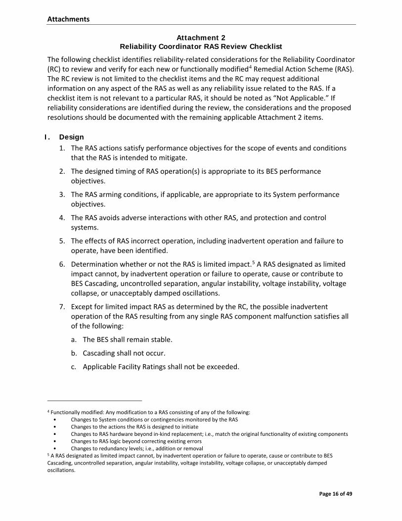
Attachments
Page 16 of 49
Attachment 2 Reliability Coordinator RAS Review Checklist
The following checklist identifies reliability-related considerations for the Reliability Coordinator (RC) to review and verify for each new or functionally modified4 Remedial Action Scheme (RAS). The RC review is not limited to the checklist items and the RC may request additional information on any aspect of the RAS as well as any reliability issue related to the RAS. If a checklist item is not relevant to a particular RAS, it should be noted as “Not Applicable.” If reliability considerations are identified during the review, the considerations and the proposed resolutions should be documented with the remaining applicable Attachment 2 items.
I. Design 1. The RAS actions satisfy performance objectives for the scope of events and conditions
that the RAS is intended to mitigate.
2. The designed timing of RAS operation(s) is appropriate to its BES performance objectives.
3. The RAS arming conditions, if applicable, are appropriate to its System performance objectives.
4. The RAS avoids adverse interactions with other RAS, and protection and control systems.
5. The effects of RAS incorrect operation, including inadvertent operation and failure to operate, have been identified.
6. Determination whether or not the RAS is limited impact.5 A RAS designated as limited impact cannot, by inadvertent operation or failure to operate, cause or contribute to BES Cascading, uncontrolled separation, angular instability, voltage instability, voltage collapse, or unacceptably damped oscillations.
7. Except for limited impact RAS as determined by the RC, the possible inadvertent operation of the RAS resulting from any single RAS component malfunction satisfies all of the following:
a. The BES shall remain stable.
b. Cascading shall not occur.
c. Applicable Facility Ratings shall not be exceeded.
4 Functionally modified: Any modification to a RAS consisting of any of the following:
• Changes to System conditions or contingencies monitored by the RAS • Changes to the actions the RAS is designed to initiate • Changes to RAS hardware beyond in-kind replacement; i.e., match the original functionality of existing components • Changes to RAS logic beyond correcting existing errors • Changes to redundancy levels; i.e., addition or removal
5 A RAS designated as limited impact cannot, by inadvertent operation or failure to operate, cause or contribute to BES Cascading, uncontrolled separation, angular instability, voltage instability, voltage collapse, or unacceptably damped oscillations.

Attachments
Page 17 of 49
d. BES voltages shall be within post-Contingency voltage limits and post-Contingency voltage deviation limits as established by the Transmission Planner and the Planning Coordinator.
e. Transient voltage responses shall be within acceptable limits as established by the Transmission Planner and the Planning Coordinator.
8. The effects of future BES modifications on the design and operation of the RAS have been identified, where applicable.
II. Implementation 1. The implementation of RAS logic appropriately correlates desired actions (outputs) with
events and conditions (inputs).
2. Except for limited impact RAS as determined by the RC, a single component failure in a RAS does not prevent the BES from meeting the same performance requirements as those required for the events and conditions for which the RAS is designed.
3. The RAS design facilitates periodic testing and maintenance.
4. The mechanism or procedure by which the RAS is armed is clearly described, and is appropriate for reliable arming and operation of the RAS for the conditions and events for which it is designed to operate.
III. RAS Retirement
RAS retirement reviews should assure that there is adequate justification for why a RAS is no longer needed.
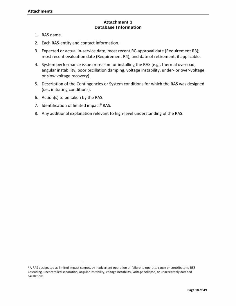
Attachments
Page 18 of 49
Attachment 3 Database Information
1. RAS name.
2. Each RAS-entity and contact information.
3. Expected or actual in-service date; most recent RC-approval date (Requirement R3); most recent evaluation date (Requirement R4); and date of retirement, if applicable.
4. System performance issue or reason for installing the RAS (e.g., thermal overload, angular instability, poor oscillation damping, voltage instability, under- or over-voltage, or slow voltage recovery).
5. Description of the Contingencies or System conditions for which the RAS was designed (i.e., initiating conditions).
6. Action(s) to be taken by the RAS.
7. Identification of limited impact6 RAS.
8. Any additional explanation relevant to high-level understanding of the RAS.
6 A RAS designated as limited impact cannot, by inadvertent operation or failure to operate, cause or contribute to BES Cascading, uncontrolled separation, angular instability, voltage instability, voltage collapse, or unacceptably damped oscillations.

Supplemental Material
Page 19 of 49
Technical Justification
4.1.1 Reliability Coordinator The Reliability Coordinator (RC) is the best-suited functional entity to perform the Remedial Action Scheme (RAS) review because the RC has the widest area reliability perspective of all functional entities and an awareness of reliability issues in neighboring RC Areas. The Wide Area purview better facilitates the evaluation of interactions among separate RAS, as well as interactions among RAS and other protection and control systems. The selection of the RC also minimizes the possibility of a conflict of interest that could exist because of business relationships among the RAS-entity, Planning Coordinator, Transmission Planner, or other entities involved in the planning or implementation of a RAS. The RC is also less likely to be a stakeholder in any given RAS and can therefore maintain objective independence.
4.1.2 Planning Coordinator The Planning Coordinator (PC) is the best-suited functional entity to perform the RAS evaluation to verify the continued effectiveness and coordination of the RAS, its inadvertent operation performance, and the performance for a single component failure. The items that must be addressed in the evaluations include: 1) RAS mitigation of the System condition(s) or event(s) for which it was designed; 2) RAS avoidance of adverse interactions with other RAS and with protection and control systems; 3) the impact of inadvertent operation; and 4) the impact of a single component failure. The evaluation of these items involves modeling and studying the interconnected transmission system, similar to the planning analyses performed by PCs.
4.1.3 RAS-entity The RAS-entity is any Transmission Owner, Generator Owner, or Distribution Provider that owns all or part of a RAS. If all of the RAS (RAS components) have a single owner, then that RAS-entity has sole responsibility for all the activities assigned within the standard to the RAS-entity. If the RAS (RAS components) have more than one owner, then each separate RAS component owner is a RAS-entity and is obligated to participate in various activities identified by the Requirements.
The standard does not stipulate particular compliance methods. RAS-entities have the option of collaborating to fulfill their responsibilities for each applicable requirement. Such collaboration and coordination may promote efficiency in achieving the reliability objectives of the requirements; however, the individual RAS-entity must be able to demonstrate its participation for compliance. As an example, the individual RAS-entities could collaborate to produce and submit a single, coordinated Attachment 1 to the reviewing RC pursuant to Requirement R1 to initiate the RAS review process.
Limited impact RAS are unique and customized assemblages of protection and control equipment that vary in complexity and impact on the reliability of the BES. These differences in RAS design, action, and risk to the BES are identified and verified within the construct of Requirements R1-R4 of PRC-012-2. The reviewing RC has the authority to designate a RAS as limited impact if the RAS cannot, by inadvertent operation or failure to operate, cause or contribute to BES Cascading, uncontrolled
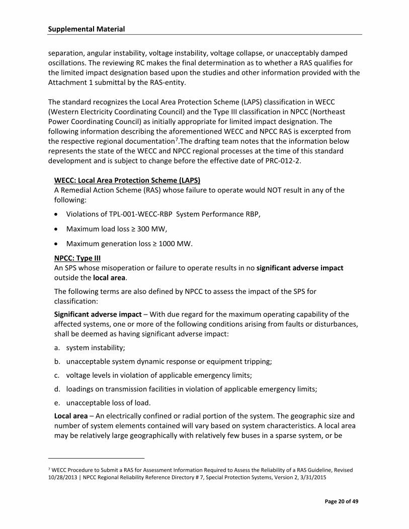
Supplemental Material
Page 20 of 49
separation, angular instability, voltage instability, voltage collapse, or unacceptably damped oscillations. The reviewing RC makes the final determination as to whether a RAS qualifies for the limited impact designation based upon the studies and other information provided with the Attachment 1 submittal by the RAS-entity. The standard recognizes the Local Area Protection Scheme (LAPS) classification in WECC (Western Electricity Coordinating Council) and the Type III classification in NPCC (Northeast Power Coordinating Council) as initially appropriate for limited impact designation. The following information describing the aforementioned WECC and NPCC RAS is excerpted from the respective regional documentation7.The drafting team notes that the information below represents the state of the WECC and NPCC regional processes at the time of this standard development and is subject to change before the effective date of PRC-012-2.
WECC: Local Area Protection Scheme (LAPS) A Remedial Action Scheme (RAS) whose failure to operate would NOT result in any of the following:
• Violations of TPL-001-WECC-RBP System Performance RBP,
• Maximum load loss ≥ 300 MW,
• Maximum generation loss ≥ 1000 MW.
NPCC: Type III An SPS whose misoperation or failure to operate results in no significant adverse impact outside the local area.
The following terms are also defined by NPCC to assess the impact of the SPS for classification:
Significant adverse impact – With due regard for the maximum operating capability of the affected systems, one or more of the following conditions arising from faults or disturbances, shall be deemed as having significant adverse impact:
a. system instability;
b. unacceptable system dynamic response or equipment tripping;
c. voltage levels in violation of applicable emergency limits;
d. loadings on transmission facilities in violation of applicable emergency limits;
e. unacceptable loss of load.
Local area – An electrically confined or radial portion of the system. The geographic size and number of system elements contained will vary based on system characteristics. A local area may be relatively large geographically with relatively few buses in a sparse system, or be
7 WECC Procedure to Submit a RAS for Assessment Information Required to Assess the Reliability of a RAS Guideline, Revised 10/28/2013 | NPCC Regional Reliability Reference Directory # 7, Special Protection Systems, Version 2, 3/31/2015

Supplemental Material
Page 21 of 49
relatively small geographically with a relatively large number of buses in a densely networked system.
A RAS implemented prior to the effective date of PRC-012-2 that has been through the regional review processes of WECC or NPCC and classified as either a Local Area Protection Scheme (LAPS) in WECC or a Type III in NPCC, is recognized as a limited impact RAS upon the effective date of PRC-012-2 for the purposes of this standard and is subject to all applicable requirements. To propose an existing RAS (a RAS implemented prior to the effective date of PRC-012-2) be designated as limited impact by the reviewing RC, the RAS-entity must prepare and submit the appropriate Attachment 1 information that includes the technical justification (evaluations) documenting that the System can meet the performance requirements (specified in Requirement R4, Parts 4.1.4 and 4.1.5) resulting from a single RAS component malfunction or failure, respectively. There is nothing that precludes a RAS-entity from working with the reviewing RC during the implementation period of PRC-012-2, in anticipation of the standard becoming enforceable. However, even if the reviewing RC determines the RAS qualifies as limited impact, the designation is not relevant until the standard becomes effective. Until then, the existing regional processes remain in effect as well as the existing RAS classifications or lack thereof. An example of a scheme that could be recognized as a limited impact RAS is a load shedding or generation rejection scheme used to mitigate the overload of a BES transmission line. The inadvertent operation of such a scheme would cause the loss of either a certain amount of generation or load. The evaluation by the RAS-entity should demonstrate that the loss of this amount of generation or load, without the associated contingency for RAS operation actually occurring, is acceptable and not detrimental to the reliability of BES; e.g., in terms of frequency and voltage stability. The failure of that scheme to operate when intended could potentially lead to the overloading of a transmission line beyond its acceptable rating. The RAS-entity would need to demonstrate that this overload, while in excess of the applicable Facility Rating, is not detrimental to the BES outside the contained area (predetermined by studies) affected by the contingency. Other examples of limited impact RAS include:
• A scheme used to protect BES equipment from damage caused by overvoltage through generation rejection or equipment tripping.
• A centrally-controlled undervoltage load shedding scheme used to protect a contained area (predetermined by studies) of the BES against voltage collapse.
• A scheme used to trip a generating unit following certain BES Contingencies to prevent the unit from going out of synch with the System; where, if the RAS fails to operate and the unit pulls out of synchronism, the resulting apparent impedance swings do not

Supplemental Material
Page 22 of 49
result in the tripping of any Transmission System Elements other than the generating unit and its directly connected Facilities.
Requirement R1 Each RAS is unique and its action(s) can have a significant impact on the reliability and integrity of the Bulk Electric System (BES); therefore, a review of a proposed new RAS or an existing RAS proposed for functional modification, or retirement (removal from service) must be completed prior to implementation. Functional modifications consists of any of the following:
• Changes to System conditions or Contingencies monitored by the RAS
• Changes to the actions the RAS is designed to initiate
• Changes to RAS hardware beyond in-kind replacement; i.e., match the original functionality of existing components
• Changes to RAS logic beyond correcting existing errors
• Changes to redundancy levels; i.e., addition or removal An example indicating the limits of an in-kind replacement of a RAS component is the replacement of one relay (or other device) with a relay (or other device) that uses similar functions. For instance, if a RAS included a CO-11 relay which was replaced by an IAC-53 relay, that would be an in-kind replacement. If the CO-11 relay were replaced by a microprocessor SEL-451 relay that used only the same functions as the original CO-11 relay, that would also be an in-kind replacement; however, if the SEL-451 relay was used to add new logic to what the CO-11 relay had provided, then the replacement relay would be a functional modification. Changes to RAS pickup levels that require no other scheme changes are not considered a functional modification. For example, System conditions require a RAS to be armed when the combined flow on two lines exceeds 500 MW. If a periodic evaluation pursuant to Requirement R4, or other assessment, indicates that the arming level should be reduced to 450 MW without requiring any other RAS changes that would not be a functional modification. Similarly, if a RAS is designed to shed load to reduce loading on a particular line below 1000 amps, then a change in the load shedding trigger from 1000 amps to 1100 amps would not be a functional modification. Another example illustrates a case where a System change may result in a RAS functional change. Assume that a generation center is connected to a load center through two transmission lines. The lines are not rated to accommodate full plant output if one line is out of service, so a RAS monitors the status of both lines and trips or ramps down the generation to a safe level following loss of either line. Later, one of the lines is tapped to serve additional load. The System that the RAS impacts now includes three lines, loss of any of which is likely to still require generation reduction. The modified RAS will need to monitor all three lines (add two line terminal status inputs to the RAS) and the logic to recognize the specific line outages would

Supplemental Material
Page 23 of 49
change, while the generation reduction (RAS output) requirement may or may not change, depending on which line is out of service. These required RAS changes would be a functional modification. Any functional modification to a RAS will need to be reviewed and approved through the process described in Requirements R1, R2, and R3. The need for such functional modifications may be identified in several ways including but not limited to the Planning evaluations pursuant to R4, incorrect operations pursuant to R5, a test failure pursuant to R8, or Planning assessments related to future additions or modifications of other facilities. See Item 4a in the Implementation Section of Attachment 1 in the Supplemental Material section for typical RAS components for which a failure may be considered. The RC has the discretion to make the final determination regarding which components should be regarded as RAS components during its review. To facilitate a review that promotes reliability, the RAS-entity(ies) must provide the reviewer with sufficient details of the RAS design, function, and operation. This data and supporting documentation are identified in Attachment 1 of this standard, and Requirement R1 mandates that the RAS-entity(ies) provide them to the reviewing Reliability Coordinator (RC). The RC that coordinates the area where the RAS is located is responsible for the review. In cases where a RAS crosses multiple RC Area boundaries, each affected RC is responsible for conducting either individual reviews or a coordinated review. Requirement R1 does not specify how far in advance of implementation the RAS-entity(ies) must provide Attachment 1 data to the reviewing RC. The information will need to be submitted early enough to allow RC review in the allotted time pursuant to Requirement R2, including resolution of any reliability issues that might be identified, in order to obtain approval of the reviewing RC. Expeditious submittal of this information is in the interest of each RAS-entity to effect a timely implementation. Requirement R2 Requirement R2 mandates that the RC perform reviews of all proposed new RAS and existing RAS proposed for functional modification, or retirement (removal from service) in its RC Area. RAS are unique and customized assemblages of protection and control equipment. As such, they have a potential to introduce reliability risks to the BES, if not carefully planned, designed, and installed. A RAS may be installed to address a reliability issue, or achieve an economic or operational advantage, and could introduce reliability risks that might not be apparent to a RAS-entity(ies). An independent review by a multi-disciplinary panel of subject matter experts with planning, operations, protection, telecommunications, and equipment expertise is an effective means of identifying risks and recommending RAS modifications when necessary. The RC is the functional entity best suited to perform the RAS reviews because it has the widest area reliability perspective of all functional entities and an awareness of reliability issues in

Supplemental Material
Page 24 of 49
neighboring RC Areas. This Wide Area purview facilitates the evaluation of interactions among separate RAS as well as interactions among the RAS and other protection and control systems. The selection of the RC also minimizes the possibility of a “conflict of interest” that could exist because of business relationships among the RAS-entity, Planning Coordinator (PC), Transmission Planner (TP), or other entities that are likely to be involved in the planning or implementation of a RAS. The RC may request assistance in RAS reviews from other parties such as the PC(s) or regional technical groups (e.g., Regional Entities); however, the RC retains responsibility for compliance with the requirement. It is recognized that the RC does not possesses more information or ability than anticipated by their functional registration as designated by NERC. The NERC Functional Model is a guideline for the development of standards and their applicability and does not contain compliance requirements. If Reliability Standards address functions that are not described in the model, the Reliability Standard requirements take precedence over the Functional Model. For further reference, please see the Introduction section of NERC’s Reliability Functional Model, Version 5, November 2009. Attachment 2 of this standard is a checklist for assisting the RC in identifying design and implementation aspects of a RAS, and for facilitating consistent reviews of each RAS submitted for review. The time frame of four full calendar months is consistent with current utility practice; however, flexibility is provided by allowing the parties to negotiate a different schedule for the review. Note, an RC may need to include this task in its reliability plan(s) for the NERC Region(s) in which it is located. Requirement R3 Requirement R3 mandates that each RAS-entity resolve all reliability issues (pertaining to its RAS) identified during the RAS review by the reviewing Reliability Coordinators. Examples of reliability issues include a lack of dependability, security, or coordination. RC approval of a RAS is considered to be obtained when the reviewing RC’s feedback to each RAS-entity indicates that either no reliability issues were identified during the review or all identified reliability issues were resolved to the RC’s satisfaction. Dependability is a component of reliability that is the measure of certainty of a device to operate when required. If a RAS is installed to meet performance requirements of NERC Reliability Standards, a failure of the RAS to operate when intended would put the System at risk of violating NERC Reliability Standards if specified Contingency(ies) or System conditions occur. This risk is mitigated by designing the RAS so that it will accomplish the intended purpose while experiencing a single RAS component failure. This is often accomplished through redundancy. Other strategies for providing dependability include “over-tripping” load or generation, or alternative automatic backup schemes. Security is a component of reliability that is the measure of certainty of a device to not operate inadvertently. False or inadvertent operation of a RAS results in taking a programmed action without the appropriate arming conditions, occurrence of specified Contingency(ies), or System conditions expected to trigger the RAS action. Typical RAS actions include shedding load or generation or re-configuring the System. Such actions, if inadvertently taken, are undesirable
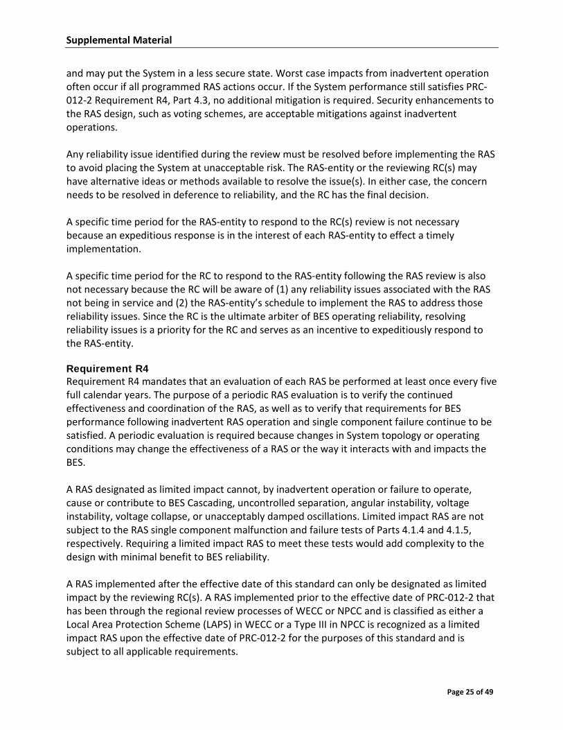
Supplemental Material
Page 25 of 49
and may put the System in a less secure state. Worst case impacts from inadvertent operation often occur if all programmed RAS actions occur. If the System performance still satisfies PRC-012-2 Requirement R4, Part 4.3, no additional mitigation is required. Security enhancements to the RAS design, such as voting schemes, are acceptable mitigations against inadvertent operations. Any reliability issue identified during the review must be resolved before implementing the RAS to avoid placing the System at unacceptable risk. The RAS-entity or the reviewing RC(s) may have alternative ideas or methods available to resolve the issue(s). In either case, the concern needs to be resolved in deference to reliability, and the RC has the final decision. A specific time period for the RAS-entity to respond to the RC(s) review is not necessary because an expeditious response is in the interest of each RAS-entity to effect a timely implementation. A specific time period for the RC to respond to the RAS-entity following the RAS review is also not necessary because the RC will be aware of (1) any reliability issues associated with the RAS not being in service and (2) the RAS-entity’s schedule to implement the RAS to address those reliability issues. Since the RC is the ultimate arbiter of BES operating reliability, resolving reliability issues is a priority for the RC and serves as an incentive to expeditiously respond to the RAS-entity. Requirement R4 Requirement R4 mandates that an evaluation of each RAS be performed at least once every five full calendar years. The purpose of a periodic RAS evaluation is to verify the continued effectiveness and coordination of the RAS, as well as to verify that requirements for BES performance following inadvertent RAS operation and single component failure continue to be satisfied. A periodic evaluation is required because changes in System topology or operating conditions may change the effectiveness of a RAS or the way it interacts with and impacts the BES. A RAS designated as limited impact cannot, by inadvertent operation or failure to operate, cause or contribute to BES Cascading, uncontrolled separation, angular instability, voltage instability, voltage collapse, or unacceptably damped oscillations. Limited impact RAS are not subject to the RAS single component malfunction and failure tests of Parts 4.1.4 and 4.1.5, respectively. Requiring a limited impact RAS to meet these tests would add complexity to the design with minimal benefit to BES reliability. A RAS implemented after the effective date of this standard can only be designated as limited impact by the reviewing RC(s). A RAS implemented prior to the effective date of PRC-012-2 that has been through the regional review processes of WECC or NPCC and is classified as either a Local Area Protection Scheme (LAPS) in WECC or a Type III in NPCC is recognized as a limited impact RAS upon the effective date of PRC-012-2 for the purposes of this standard and is subject to all applicable requirements.
Supplemental Material
Page 26 of 49
Requirement R4 also clarifies that the RAS single component failure and inadvertent operation tests do not apply to RAS which are determined to be limited impact. Requiring a limited impact RAS to meet the single component failure and inadvertent operation tests would just add complexity to the design with little or no improvement in the reliability of the BES. For existing RAS, the initial performance of Requirement R4 must be completed within five full calendar years of the effective date of PRC-012-2. For new or functionally modified RAS, the initial performance of the requirement must be completed within five full calendar years of the RAS approval date by the reviewing RC(s). Five full calendar years was selected as the maximum time frame between evaluations based on the time frames for similar requirements in Reliability Standards PRC-006, PRC-010, and PRC-014. The RAS evaluation can be performed sooner if it is determined that material changes to System topology or System operating conditions could potentially impact the effectiveness or coordination of the RAS. System changes also have the potential to alter the reliability impact of limited impact RAS on the BES. Requirement 4, Part 4.1.3 explicitly requires the periodic evaluation of limited impact RAS to verify the limited impact designation remains applicable. The periodic RAS evaluation will typically lead to one of the following outcomes: 1) affirmation that the existing RAS is effective; 2) identification of changes needed to the existing RAS; or, 3) justification for RAS retirement. The items required to be addressed in the evaluations (Requirement R4, Parts 4.1.1 through 4.1.5) are planning analyses that may involve modeling of the interconnected transmission system to assess BES performance. The PC is the functional entity best suited to perform the analyses because they have a wide-area planning perspective. To promote reliability, the PC is required to provide the results of the evaluation to each impacted Transmission Planner and Planning Coordinator, in addition to each reviewing RC and RAS-entity. In cases where a RAS crosses PC boundaries, each affected PC is responsible for conducting either individual evaluations or participating in a coordinated evaluation. The intent of Requirement R4, Part 4.1.4 is to verify that the possible inadvertent operation of the RAS (other than limited impact RAS), caused by the malfunction of a single component of the RAS, meet the same System performance requirements as those required for the Contingency(ies) or System conditions for which it is designed. If the RAS is designed to meet one of the planning events (P0-P7) in TPL-001-4, the possible inadvertent operation of the RAS must meet the same performance requirements listed in the standard for that planning event. The requirement clarifies that the inadvertent operation to be considered is only that caused by the malfunction of a single RAS component. This allows features to be designed into the RAS to improve security, such that inadvertent operation due to malfunction of a single component is prevented; otherwise, the RAS inadvertent operation must satisfy Requirement R4, Part 4.1.4. The intent of Requirement R4, Part 4.1.4 is also to verify that the possible inadvertent operation of the RAS (other than limited impact RAS) installed for an extreme event in TPL-001-4 or for some other Contingency or System conditions not defined in TPL-001-4 (therefore without performance requirements), meet the minimum System performance requirements of Category P7 in Table 1 of NERC Reliability Standard TPL-001-4. However, instead of referring to the TPL

Supplemental Material
Page 27 of 49
standard, the requirement lists the System performance requirements that a potential inadvertent operation must satisfy. The performance requirements listed (Requirement R4, Parts 4.1.4.1 – 4.1.4.5) are the ones that are common to all planning events (P0-P7) listed in TPL-001-4. With reference to Requirement 4, Part 4.1.4, note that the only differences in performance requirements among the TPL (P0-P7) events (not common to all of them) concern Non-Consequential Load Loss and interruption of Firm Transmission Service. It is not necessary for Requirement R4, Part 4.1.4 to specify performance requirements related to these areas because a RAS is only allowed to drop non-consequential load or interrupt Firm Transmission Service if that action is allowed for the Contingency for which it is designed. Therefore, the inadvertent operation should automatically meet Non-Consequential Load Loss or interrupting Firm Transmission Service performance requirements for the Contingency(ies) for which it was designed. The intent of Requirement R4, Part 4.1.5 is to verify that a single component failure in a RAS, other than limited impact RAS, when the RAS is intended to operate, does not prevent the BES from meeting the same performance requirements (defined in Reliability Standard TPL-001-4 or its successor) as those required for the events and conditions for which the RAS is designed. This analysis is needed to ensure that changing System conditions do not result in the single component failure requirement not being met. The following is an example of a single component failure causing the System to fail to meet the performance requirements for the P1 event for which the RAS was installed. Consider the instance where a three-phase Fault (P1 event) results in a generating plant becoming unstable (a violation of the System performance requirements of TPL-001-4). To resolve this, a RAS is installed to trip a single generating unit which allows the remaining units at the plant to remain stable. If failure of a single component (e.g., relay) in the RAS results in the RAS failing to operate for the P1 event, the generating plant would become unstable (failing to meet the System performance requirements of TPL-001-4 for a P1 event). Requirement R4, Part 4.1.5 does not mandate that all RAS have redundant components. For example:
• Consider the instance where a RAS is installed to mitigate an extreme event in TPL-001-4. There are no System performance requirements for extreme events; therefore, the RAS does not need redundancy to meet the same performance requirements as those required for the events and conditions for which the RAS was designed.
• Consider a RAS that arms more load or generation than necessary such that failure of the RAS to drop a portion of load or generation due to that single component failure will still result in satisfactory System performance, as long as tripping the total armed amount of load or generation does not cause other adverse impacts to reliability.
Supplemental Material
Page 28 of 49
The scope of the periodic evaluation does not include a new review of the physical implementation of the RAS, as this was confirmed by the RC during the initial review and verified by subsequent functional testing. However, it is possible that a RAS design which previously satisfied requirements for inadvertent RAS operation and single component failure by means other than component redundancy may fail to satisfy these requirements at a later time, and must be evaluated with respect to the current System. For example, if the actions of a particular RAS include tripping load, load growth could occur over time that impacts the amount of load to be tripped. These changes could result in tripping too much load upon inadvertent operation and result in violations of Facility Ratings. Alternatively, the RAS might be designed to trip more load than necessary (i.e., “over trip”) in order to satisfy single component failure requirements. System changes could result in too little load being tripped and unacceptable BES performance if one of the loads failed to trip. Requirement R5 The correct operation of a RAS is important to maintain the reliability and integrity of the BES. Any incorrect operation of a RAS indicates the RAS effectiveness and/or coordination may have been compromised. Therefore, all operations of a RAS and failures of a RAS to operate when expected must be analyzed to verify that the RAS operation was consistent with its intended functionality and design. A RAS operational performance analysis is intended to: (1) verify RAS operation is consistent with implemented design; or (2) identify RAS performance deficiencies that manifested in the incorrect RAS operation or failure of RAS to operate when expected. The 120 full calendar day time frame for the completion of RAS operational performance analysis aligns with the time frame established in Requirement R1 from PRC-004-4 regarding the investigation of a Protection System Misoperation; however, flexibility is provided by allowing the parties to negotiate a different schedule for the analysis. To promote reliability, the RAS-entity(s) is required to provide the results of RAS operational performance analyses to its reviewing RC(s) if the analyses revealed a deficiency. The RAS-entity(ies) may need to collaborate with its associated Transmission Planner to comprehensively analyze RAS operational performance. This is because a RAS operational performance analysis involves verifying that the RAS operation was triggered correctly (Part 5.1.1), responded as designed (Part 5.1.2), and that the resulting BES response (Parts 5.1.3 and 5.1.4) was consistent with the intended functionality and design of the RAS. Ideally, when there is more than one RAS-entity for a RAS, the RAS-entities would collaborate to conduct and submit a single, coordinated operational performance analysis. Requirement R6 RAS deficiencies potentially pose a reliability risk to the BES. RAS deficiencies may be identified in the periodic RAS evaluation conducted by the PC in Requirement R4, in the operational analysis conducted by the RAS-entity in Requirement R5, or in the functional test performed by the RAS-entity(ies) in Requirement R8. To mitigate potential reliability risks, Requirement R6

Supplemental Material
Page 29 of 49
mandates that each RAS-entity participate in developing a CAP that establishes the mitigation actions and timetable necessary to address the deficiency.
The RAS-entity(ies) that owns the RAS components, is responsible for the RAS equipment, and is in the best position to develop the timelines and perform the necessary work to correct RAS deficiencies. If necessary, the RAS-entity(ies) may request assistance with development of the CAP from other parties such as its Transmission Planner or Planning Coordinator; however, the RAS-entity has the responsibility for compliance with this requirement. A CAP may require functional changes be made to a RAS. In this case, Attachment 1 information must be submitted to the reviewing RC(s), an RC review must be performed to obtain RC approval before the RAS-entity can place RAS modifications in service, per Requirements R1, R2, and R3. Depending on the complexity of the issues, development of a CAP may require study, engineering or consulting work. A timeframe of six full calendar months is allotted to allow enough time for RAS-entity collaboration on the CAP development, while ensuring that deficiencies are addressed in a reasonable time. Ideally, when there is more than one RAS-entity for a RAS, the RAS-entities would collaborate to develop and submit a single, coordinated CAP. A RAS deficiency may require the RC or Transmission Operator to impose operating restrictions so the System can operate in a reliable way until the RAS deficiency is resolved. The possibility of such operating restrictions will incent the RAS-entity to resolve the issue as quickly as possible. The following are example situations of when a CAP is required:
• A determination after a RAS operation/non-operation investigation that the RAS did not meet performance expectations or did not operate as designed.
• Periodic planning assessment reveals RAS changes are necessary to correct performance or coordination issues.
• Equipment failures.
• Functional testing identifies that a RAS is not operating as designed. Requirement R7 Requirement R7 mandates that each RAS-entity implement its CAP developed in Requirement R6 which mitigates the deficiencies identified in Requirements R4, R5, or R8. By definition, a CAP is: “A list of actions and an associated timetable for implementation to remedy a specific problem.” A CAP can be modified if necessary to account for adjustments to the actions or scheduled timetable of activities. If the CAP is changed, the RAS-entity must notify the reviewing Reliability
Supplemental Material
Page 30 of 49
Coordinator(s). The RAS-entity must also notify the Reliability Coordinator(s) when the CAP has been completed. The implementation of a properly developed CAP ensures that RAS deficiencies are mitigated in a timely manner. A RAS deficiency may require the RC or Transmission Operator to impose operating restrictions so the System can operate in a reliable way until the CAP is completed. The possibility of such operating restrictions will incent the RAS-entity to complete the CAP as quickly as possible. Requirement R8 The reliability objective of Requirement R8 is to test the non-Protection System components of a RAS (controllers such as programmable logic controllers (PLCs)) and to verify the overall performance of the RAS through functional testing. Functional tests validate RAS operation by ensuring System states are detected and processed, and that actions taken by the controls are correct and occur within the expected time using the in-service settings and logic. Functional testing is aimed at assuring overall RAS performance and not the component focused testing contained in the PRC-005 maintenance standard. Since the functional test operates the RAS under controlled conditions with known System states and expected results, testing and analysis can be performed with minimum impact to the BES and should align with expected results. The RAS-entity is in the best position to determine the testing procedure and schedule due to their overall knowledge of the RAS design, installation, and functionality. Periodic testing provides the RAS-entity assurance that latent failures may be identified and also promotes identification of changes in the System that may have introduced latent failures. The six and twelve full calendar year functional testing intervals are greater than the annual or bi-annual periodic testing performed in some NERC Regions. However, these intervals are a balance between the resources required to perform the testing and the potential reliability impacts to the BES created by undiscovered latent failures that could cause an incorrect operation of the RAS. Longer test intervals for limited impact RAS are acceptable because incorrect operations or failures to operate present a low reliability risk to the Bulk Power System. Functional testing is not synonymous with end-to-end testing. End-to-end testing is an acceptable method but may not be feasible for many RAS. When end-to-end testing is not possible, a RAS-entity may use a segmented functional testing approach. The segments can be tested individually negating the need for complex maintenance schedules. In addition, actual RAS operation(s) can be used to fulfill the functional testing requirement. If a RAS does not operate in its entirety during a System event or System conditions do not allow an end-to-end scheme test, then the segmented approach should be used to fulfill this Requirement. Functional testing includes the testing of all RAS inputs used for detection, arming, operating, and data collection. Functional testing, by default operates the processing logic and infrastructure of a RAS, but focuses on the RAS inputs as well as the actions initiated by RAS

Supplemental Material
Page 31 of 49
outputs to address the System condition(s) for which the RAS is designed. All segments and components of a RAS must be tested or have proven operations within the applicable maximum test interval to demonstrate compliance with the Requirement. As an example of segment testing, consider a RAS controller implemented using a PLC that receives System data, such as loading or line status, from distributed devices. These distributed devices could include meters, protective relays, or other PLCs. In this example RAS, a line protective relay is used to provide an analog metering quantity to the RAS control PLC. A functional test would verify that the System data is received from the protective relay by the PLC, processed by the PLC, and that PLC outputs are appropriate. There is no need to verify the protective relay’s ability to measure the power system quantities, as this is a requirement for Protection Systems used as RAS in PRC-005, Table 1-1, Component Type – Protective Relay. Rather the functional test is focused on the use of the protective relay data at the PLC, including the communications data path from relay to PLC if this data is essential for proper RAS operation. Additionally, if the control signal back to the protective relay is also critical to the proper functioning of this example RAS, then that path is also verified up to the protective relay. This example describes a test for one segment of a RAS which verifies RAS action, verifies PLC control logic, and verifies RAS communications. IEEE C37.233, “IEEE Guide for Power System Protection Testing,” 2009 section 8 (particularly 8.3-8.5), provides an overview of functional testing. The following opens section 8.3:
Proper implementation requires a well-defined and coordinated test plan for performance evaluation of the overall system during agreed maintenance intervals. The maintenance test plan, also referred to as functional system testing, should include inputs, outputs, communication, logic, and throughput timing tests. The functional tests are generally not component-level testing, rather overall system testing. Some of the input tests may need to be done ahead of overall system testing to the extent that the tests affect the overall performance. The test coordinator or coordinators need to have full knowledge of the intent of the scheme, isolation points, simulation scenarios, and restoration to normal procedures. The concept is to validate the overall performance of the scheme, including the logic where applicable, to validate the overall throughput times against system modeling for different types of Contingencies, and to verify scheme performance as well as the inputs and outputs.
If a RAS passes a functional test, it is not necessary to provide that specific information to the RC because that is the expected result and requires no further action. If a segment of a RAS fails a functional test, the status of that degraded RAS is required to be reported (in Real-time) to the Transmission Operator via PRC-001, Requirement R6, then to the RC via TOP-001-3, Requirement R8. See Phase 2 of Project 2007-06 for the mapping document from PRC-001 to other standards regarding notification of RC by TOP if a deficiency is found during testing. Consequently, it is not necessary to include a similar requirement in this standard. The initial test interval begins on the effective date of the standard pursuant to the implementation plan. Subsequently, the maximum allowable interval between functional tests

Supplemental Material
Page 32 of 49
is six full calendar years for RAS that are not designated as limited impact RAS and twelve full calendar years for RAS that are designated as limited impact RAS. The interval between tests begins on the date of the most recent successful test for each individual segment or end-to-end test. A successful test of one segment only resets the test interval clock for that segment. A RAS-entity may choose to count a correct RAS operation as a qualifying functional test for those RAS segments which operate. If a System event causes a correct, but partial RAS operation, separate functional tests of the segments that did not operate are still required within the maximum test interval that started on the date of the previous successful test of those (non-operating) segments in order to be compliant with Requirement R8. Requirement R9 The RAS database required to be maintained by the RC in Requirement R9 ensures information regarding existing RAS is available. Attachment 3 contains the minimum information that is required to be included about each RAS listed in the database. Additional information can be requested by the RC. The database enables the RC to provide other entities high-level information on existing RAS that could potentially impact the operational and/or planning activities of that entity. The information provided is sufficient for an entity with a reliability need to evaluate whether the RAS can impact its System. For example, a RAS performing generation rejection to mitigate an overload on a transmission line may cause a power flow change within an adjacent entity area. This entity should be able to evaluate the risk that a RAS poses to its System from the high-level information provided in the RAS database. The RAS database does not need to list detailed settings or modeling information, but the description of the System performance issues, System conditions, and the intended corrective actions must be included. If additional details about the RAS operation are required, the entity may obtain the contact information of the RAS-entity from the RC.
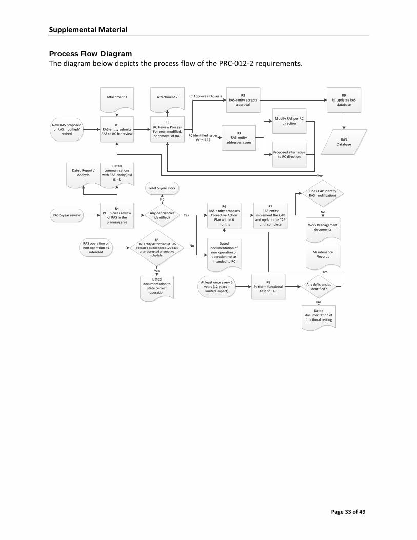
Supplemental Material
Page 33 of 49
Process Flow Diagram The diagram below depicts the process flow of the PRC-012-2 requirements.
R1RAS-entity submits
RAS to RC for review
R2RC Review ProcessFor new, modified, or removal of RAS
New RAS proposed or RAS modified/
retired
RAS 5-year review
R4PC – 5-year review
of RAS in the planning area
RAS operation or non operation as
intended
R5RAS entity determines if RAS
operated as intended (120 days or an accepted alternative
schedule)
Dated documentation to
state correct operation
Yes
RAS Database
Attachment 1 R9RC updates RAS
database
R3RAS-entity accepts
approval
R3RAS-entity
addresses issues
RC Approves RAS as is
RC identified issuesWith RAS
Modify RAS per RC direction
Proposed alternative to RC direction
Attachment 2
Dated Report / Analysis
Dated communications
with RAS-entity(ies) & RC
Dated documentation of non operation or operation not as intended to RC
No
R6RAS-entity proposes
Corrective Action Plan within 6
months
R7RAS-entity
implement the CAP and update the CAP
until complete Work Management documents
Maintenance Records
Any deficiencies identified? Yes
reset 5-year clock
No
Does CAP identify RAS modification?
No
Yes
At least once every 6 years (12 years – limited impact)
R8Perform functional
test of RAS
Dated documentation of functional testing
Any deficiencies identified?
No
Yes

Supplemental Material
Page 34 of 49
Technical Justifications for Attachment 1 Content Supporting Documentation for RAS Review
To perform an adequate review of the expected reliability implications of a Remedial Action Scheme (RAS), it is necessary for the RAS-entity(ies) to provide a detailed list of information describing the RAS to the reviewing RC. If there are multiple RAS-entities for a single RAS, information will be needed from all RAS-entities. Ideally, in such cases, a single RAS-entity will take the lead to compile all the data identified into a single Attachment 1. The necessary data ranges from a general overview of the RAS to summarized results of transmission planning studies, to information about hardware used to implement the RAS. Coordination between the RAS and other RAS and protection and control systems will be examined for possible adverse interactions. This review can include wide-ranging electrical design issues involving the specific hardware, logic, telecommunications, and other relevant equipment and controls that make up the RAS. Attachment 1
The following checklist identifies important RAS information for each new or functionally modified8 RAS that the RAS-entity shall document and provide to the RC for review pursuant to Requirement R1. When a RAS has been previously reviewed, only the proposed modifications to that RAS require review; however, it will be helpful to each reviewing RC if the RAS-entity provides a summary of the existing RAS functionality.
I. General
1. Information such as maps, one-line drawings, substation and schematic drawings that identify the physical and electrical location of the RAS and related facilities.
Provide a description of the RAS to give an overall understanding of the functionality and a map showing the location of the RAS. Identify other protection and control systems requiring coordination with the RAS. See RAS Design below for additional information.
Provide a single-line drawing(s) showing all sites involved. The drawing(s) should provide sufficient information to allow the RC review team to assess design reliability, and should include information such as the bus arrangement, circuit breakers, the associated switches, etc. For each site, indicate whether detection, logic, action, or a combination of these is present.
2. Functionality of new RAS or proposed functional modifications to existing RAS and documentation of the pre- and post-modified functionality of the RAS.
8 Functionally modified: Any modification to a RAS consisting of any of the following:
• Changes to System conditions or contingencies monitored by the RAS • Changes to the actions the RAS is designed to initiate • Changes to RAS hardware beyond in-kind replacement; i.e., match the original functionality of existing components • Changes to RAS logic beyond correcting existing errors • Changes to redundancy levels; i.e., addition or removal

Supplemental Material
Page 35 of 49
3. The Corrective Action Plan (CAP) if RAS modifications are proposed in a CAP. [Reference NERC Reliability Standard PRC-012-2, Requirements R5 and R7]
Provide a description of any functional modifications to a RAS that are part of a CAP that are proposed to address performance deficiency(ies) identified in the periodic evaluation pursuant to Requirement R4, the analysis of an actual RAS operation pursuant to Requirement R5, or functional test failure pursuant to Requirement R8. A copy of the most recent CAP must be submitted in addition to the other data specified in Attachment 1.
4. Initial data to populate the RAS database.
a. RAS name.
b. Each RAS-entity and contact information.
c. Expected or actual in-service date; most recent (Requirement R3) RC-approval date; most recent five full calendar year (Requirement R4) evaluation date; and, date of retirement, if applicable.
d. System performance issue or reason for installing the RAS (e.g., thermal overload, angular instability, poor oscillation damping, voltage instability, under-/over-voltage, slow voltage recovery).
e. Description of the Contingencies or System conditions for which the RAS was designed (initiating conditions).
f. Corrective action taken by the RAS.
g. Identification of limited impact9 RAS.
h. Any additional explanation relevant to high level understanding of the RAS.
Note: This is the same information as is identified in Attachment 3. Supplying the data at this point in the review process ensures a more complete review and minimizes any administrative burden on the reviewing RC(s).
II. Functional Description and Transmission Planning Information
1. Contingencies and System conditions that the RAS is intended to remedy. [Reference NERC Reliability Standards PRC-012, R1.2 and PRC-013, R1.1] a. The System conditions that would result if no RAS action occurred should be
identified. b. Include a description of the System conditions that should arm the RAS so as to be
ready to take action upon subsequent occurrence of the critical System Contingencies or other operating conditions when RAS action is intended to occur. If no arming conditions are required, this should also be stated.
9 A RAS designated as limited impact cannot, by inadvertent operation or failure to operate, cause or contribute to BES Cascading, uncontrolled separation, angular instability, voltage instability, voltage collapse, or unacceptably damped oscillations.

Supplemental Material
Page 36 of 49
c. Event-based RAS are triggered by specific Contingencies that initiate mitigating action. Condition-based RAS may also be initiated by specific Contingencies, but specific Contingencies are not always required. These triggering Contingencies and/or conditions should be identified.
2. The actions to be taken by the RAS in response to disturbance conditions. [Reference NERC Reliability Standards PRC-012, R1.2 and PRC-013, R1.2]
Mitigating actions are designed to result in acceptable System performance. These actions should be identified, including any time constraints and/or “backup” mitigating measures that may be required in case of a single RAS component failure.
3. A summary of technical studies, if applicable, demonstrating that the proposed RAS actions satisfy System performance objectives for the scope of System events and conditions that the RAS is intended to remedy. The technical studies summary shall also include information such as the study year(s), System conditions, and Contingencies analyzed on which the RAS design is based, and the date those technical studies were performed. [Reference NEC Reliability Standard PRC-014, R3.2]
Review the scheme purpose and impact to ensure it is (still) necessary, serves the intended purposes, and meets current performance requirements. While copies of the full, detailed studies may not be necessary, any abbreviated descriptions of the studies must be detailed enough to allow the reviewing RC(s) to be convinced of the need for the scheme and the results of RAS-related operations.
4. Information regarding any future System plans that will impact the RAS. [Reference NERC Reliability Standard PRC-014, R3.2]
The RC’s other responsibilities under the NERC Reliability Standards focus on the Operating Horizon, rather than the Planning Horizon. As such, the RC is less likely to be aware of any longer range plans that may have an impact on the proposed RAS. Such knowledge of future Plans is helpful to provide perspective on the capabilities of the RAS.
5. RAS-entity proposal and justification for limited impact designation, if applicable.
A RAS designated as limited impact cannot, by inadvertent operation or failure to operate, cause or contribute to BES Cascading, uncontrolled separation, angular instability, voltage instability, voltage collapse, or unacceptably damped oscillations. A RAS implemented prior to the effective date of PRC-012-2 that has been through the regional review processes of WECC or NPCC and is classified as either a Local Area Protection Scheme (LAPS) in WECC or a Type 3 in NPCC is recognized as a limited impact RAS upon the effective date of PRC-012-2 for the purposes of this standard and is subject to all applicable requirements.
6. Documentation describing the System performance resulting from the possible inadvertent operation of the RAS, except for limited impact RAS, caused by any single RAS component malfunction. Single component malfunctions in a RAS not determined to be limited impact must satisfy all of the following: [Reference NERC Reliability Standard PRC-012, R1.4]
Supplemental Material
Page 37 of 49
a. The BES shall remain stable.
b. Cascading shall not occur.
c. Applicable Facility Ratings shall not be exceeded.
d. BES voltages shall be within post-Contingency voltage limits and post-Contingency voltage deviation limits as established by the Transmission Planner and the Planning Coordinator.
e. Transient voltage responses shall be within acceptable limits as established by the Transmission Planner and the Planning Coordinator.
7. An evaluation indicating that the RAS settings and operation avoids adverse interactions with other RAS, and protection and control systems. [Reference NERC Reliability Standards PRC-012, R1.5 and PRC-014, R3.4]
RAS are complex schemes that may take action such as tripping load or generation or re-configuring the System. Many RAS depend on sensing specific System configurations to determine whether they need to arm or take actions. An examples of an adverse interaction: A RAS that reconfigures the System also changes the available Fault duty, which can affect distance relay overcurrent (“fault detector”) supervision and ground overcurrent protection coordination.
8. Identification of other affected RCs.
This information is needed to aid in information exchange among all affected entities and coordination of the RAS with other RAS and protection and control systems.
III. Implementation
1. Documentation describing the applicable equipment used for detection, dc supply, communications, transfer trip, logic processing, control actions, and monitoring.
Detection Detection and initiating devices, whether for arming or triggering action, should be designed to be secure. Several types of devices have been commonly used as disturbance, condition, or status detectors:
• Line open status (event detectors),
• Protective relay inputs and outputs (event and parameter detectors),
• Transducer and IED (analog) inputs (parameter and response detectors),
• Rate of change (parameter and response detectors).
DC Supply Batteries and charges, or other forms of dc supply for RAS, are commonly also used for Protection Systems. This is acceptable, and maintenance of such supplies is covered by PRC-005. However, redundant RAS, when used, should be supplied from separately protected (fused or breakered) circuits.

Supplemental Material
Page 38 of 49
Communications: Telecommunications Channels Telecommunications channels used for sending and receiving RAS information between sites and/or transfer trip devices should meet at least the same criteria as other relaying protection communication channels. Discuss performance of any non-deterministic communication systems used (such as Ethernet).
The scheme logic should be designed so that loss of the channel, noise, or other channel or equipment failure will not result in a false operation of the scheme.
It is highly desirable that the channel equipment and communications media (power line carrier, microwave, optical fiber, etc.) be owned and maintained by the RAS-entity, or perhaps leased from another entity familiar with the necessary reliability requirements. All channel equipment should be monitored and alarmed to the dispatch center so that timely diagnostic and repair action shall take place upon failure. Publicly switched telephone networks are generally an undesirable option.
Communication channels should be well labeled or identified so that the personnel working on the channel can readily identify the proper circuit. Channels between entities should be identified with a common name at all terminals.
Transfer Trip Transfer trip equipment, when separate from other RAS equipment, should be monitored and labeled similarly to the channel equipment.
Logic Processing All RAS require some form of logic processing to determine the action to take when the scheme is triggered. Required actions are always scheme dependent. Different actions may be required at different arming levels or for different Contingencies. Scheme logic may be achievable by something as simple as wiring a few auxiliary relay contacts or by much more complex logic processing.
Platforms that have been used reliably and successfully include PLCs in various forms, personal computers (PCs), microprocessor protective relays, remote terminal units (RTUs), and logic processors. Single-function relays have been used historically to implement RAS, but this approach is now less common except for very simple new RAS or minor additions to existing RAS.
Control Actions RAS action devices may include a variety of equipment such as transfer trip, protective relays, and other control devices. These devices receive commands from the logic processing function (perhaps through telecommunication facilities) and initiate RAS actions at the sites where action is required.
Monitoring by SCADA/EMS should include at least
• Whether the scheme is in service or out of service.
For RAS that are armed manually, the arming status may be the same as whether the RAS is in service or out of service.

Supplemental Material
Page 39 of 49
For RAS that are armed automatically, these two states are independent because a RAS that has been placed in service may be armed or unarmed based on whether the automatic arming criteria have been met.
• The current operational state of the scheme (available or not).
• In cases where the RAS requires single component failure performance; e.g., redundancy, the minimal status indications should be provided separately for each RAS.
The minimum status is generally sufficient for operational purposes; however, where possible it is often useful to provide additional information regarding partial failures or the status of critical components to allow the RAS-entity to more efficiently troubleshoot a reported failure. Whether this capability exists will depend in part on the design and vintage of equipment used in the RAS. While all schemes should provide the minimum level of monitoring, new schemes should be designed with the objective of providing monitoring at least similar to what is provided for microprocessor-based Protection Systems.
2. Information on detection logic and settings/parameters that control the operation of the RAS. [Reference NERC Reliability Standards PRC-012, R1.2 and PRC-013, R1.3]
Several methods to determine line or other equipment status are in common use, often in combination:
a. Auxiliary switch contacts from circuit breakers and disconnect switches (52a/b, 89a/b)—the most common status monitor; “a” contacts exactly emulate actual breaker status, while “b” contacts are opposite to the status of the breaker;
b. Undercurrent detection—a low level indicates an open condition, including at the far end of a line; pickup is typically slightly above the total line-charging current;
c. Breaker trip coil current monitoring—typically used when high-speed RAS response is required, but usually in combination with auxiliary switch contacts and/or other detection because the trip coil current ceases when the breaker opens; and
d. Other detectors such as angle, voltage, power, frequency, rate of change of the aforementioned, out of step, etc. are dependent on specific scheme requirements, but some forms may substitute for or enhance other monitoring described in items ‘a’, ‘b’, and ‘c’ above.
Both RAS arming and action triggers often require monitoring of analog quantities such as power, current, and voltage at one or more locations and are set to detect a specific level of the pertinent quantity. These monitors may be relays, meters, transducers, or other devices
3. Documentation showing that any multifunction device used to perform RAS function(s), in addition to other functions such as protective relaying or SCADA, does not compromise the reliability of the RAS when the device is not in service or is being maintained.
Supplemental Material
Page 40 of 49
In this context, a multifunction device (e.g., microprocessor-based relay) is a single component that is used to perform the function of a RAS in addition to protective relaying and/or SCADA simultaneously. It is important that other applications in the multifunction device do not compromise the functionality of the RAS when the device is in service or when it is being maintained. The following list outlines considerations when the RAS function is applied in the same microprocessor-based relay as equipment protection functions:
a. Describe how the multifunction device is applied in the RAS.
b. Show the general arrangement and describe how the multi-function device is labeled in the design and application, so as to identify the RAS and other device functions.
c. Describe the procedures used to isolate the RAS function from other functions in the device.
d. Describe the procedures used when each multifunction device is removed from service and whether coordination with other protection schemes is required.
e. Describe how each multifunction device is tested, both for commissioning and during periodic maintenance testing, with regard to each function of the device.
f. Describe how overall periodic RAS functional and throughput tests are performed if multifunction devices are used for both local protection and RAS.
g. Describe how upgrades to the multifunction device, such as firmware upgrades, are accomplished. How is the RAS function taken into consideration?
Other devices that are usually not considered multifunction devices such as auxiliary relays, control switches, and instrument transformers may serve multiple purposes such as protection and RAS. Similar concerns apply for these applications as noted above.
4. Documentation describing the System performance resulting from a single component failure in the RAS, except for limited impact RAS, when the RAS is intended to operate. A single component failure in a RAS not determined to be limited impact must not prevent the BES from meeting the same performance requirements (defined in Reliability Standard TPL-001-4 or its successor) as those required for the events and conditions for which the RAS is designed. The documentation should describe or illustrate how the design achieves this objective. [Reference NERC Reliability Standard PRC-012, R1.3]
RAS automatic arming, if applicable, is vital to RAS and System performance and is therefore included in this requirement.
Acceptable methods to achieve this objective include, but are not limited to the following:
a. Providing redundancy of RAS components. Typical examples are listed below:
i. Protective or auxiliary relays used by the RAS.

Supplemental Material
Page 41 of 49
ii. Communications systems necessary for correct operation of the RAS.
iii. Sensing devices used to measure electrical or other quantities used by the RAS.
iv. Station dc supply associated with RAS functions.
v. Control circuitry associated with RAS functions through the trip coil(s) of the circuit breakers or other interrupting devices.
vi. Logic processing devices that accept System inputs from RAS components or other sources, make decisions based on those inputs, or initiate output signals to take remedial actions.
b. Arming more load or generation than necessary such that failure of the RAS to drop a portion of load or generation due to that single component failure will still result in satisfactory System performance, as long as tripping the total armed amount of load or generation does not cause other adverse impacts to reliability.
c. Using alternative automatic actions to back up failures of single RAS components.
d. Manual backup operations, using planned System adjustments such as Transmission configuration changes and re-dispatch of generation, if such adjustments are executable within the time duration applicable to the Facility Ratings.
5. Documentation describing the functional testing process.
IV. RAS Retirement The following checklist identifies important RAS information for each existing RAS to be retired that the RAS-entity shall document and provide to the Reliability Coordinator for review pursuant to Requirement R1.
1. Information necessary to ensure that the Reliability Coordinator is able to understand the physical and electrical location of the RAS and related facilities.
2. A summary of technical studies and technical justifications, if applicable, upon which the decision to retire the RAS is based.
3. Anticipated date of RAS retirement.
While the documentation necessary to evaluate RAS removals is not as extensive as for new or functionally modified RAS, it is still vital that, when the RAS is no longer available, System performance will still meet the appropriate (usually TPL) requirements for the Contingencies or System conditions that the RAS had been installed to remediate.

Supplemental Material
Page 42 of 49
Technical Justification for Attachment 2 Content Reliability Coordinator RAS Review Checklist Attachment 2 is a checklist provided to facilitate consistent reviews continent-wide for new or functionally modified RAS prior to the RAS installation. The checklist is meant to assist the RC in identifying reliability-related considerations relevant to various aspects of RAS design and implementation.
Technical Justifications for Attachment 3 Content
Database Information Attachment 3 contains the minimum information that the RC must consolidate into its database for each RAS in its area.
1. RAS name.
• The name used to identify the RAS.
2. Each RAS-entity and contact information.
• A reliable phone number or email address should be included to contact each RAS-entity if more information is needed.
3. Expected or actual in-service date; most recent (Requirement R3) RC-approval date; most recent five full calendar year (Requirement R4) evaluation date; and, date of retirement, if applicable.
• Specify each applicable date.
4. System performance issue or reason for installing the RAS (e.g., thermal overload, angular instability, poor oscillation damping, voltage instability, under-/over-voltage, slow voltage recovery).
• A short description of the reason for installing the RAS is sufficient, as long as the main System issues addressed by the RAS can be identified by someone with a reliability need.
5. Description of the Contingencies or System conditions for which the RAS was designed (initiating conditions).
• A high level summary of the conditions/Contingencies is expected. Not all combinations of conditions are required to be listed.
6. Corrective action taken by the RAS.
• A short description of the actions should be given. For schemes shedding load or generation, the maximum amount of megawatts should be included.

Supplemental Material
Page 43 of 49
7. Identification of limited impact10 RAS.
• Specify whether or not the RAS is designated as limited impact.
8. Any additional explanation relevant to high-level understanding of the RAS.
• If deemed necessary, any additional information can be included in this section, but is not mandatory.
10 A RAS designated as limited impact cannot, by inadvertent operation or failure to operate, cause or contribute to BES Cascading, uncontrolled separation, angular instability, voltage instability, voltage collapse, or unacceptably damped oscillations.

Supplemental Material
Page 44 of 49
Rationale Rationale for Requirement R1: Each Remedial Action Scheme (RAS) is unique and its action(s) can have a significant impact on the reliability and integrity of the Bulk Electric System (BES). Therefore, a review of a proposed new RAS or an existing RAS proposed for functional modification or retirement; i.e., removal from service must be completed prior to implementation or retirement. Functional modifications consist of any of the following:
• Changes to System conditions or Contingencies monitored by the RAS
• Changes to the actions the RAS is designed to initiate
• Changes to RAS hardware beyond in-kind replacement; i.e., match the original functionality of existing components
• Changes to RAS logic beyond correcting existing errors
• Changes to redundancy levels; i.e., addition or removal To facilitate a review that promotes reliability, the RAS-entity must provide the reviewer with sufficient details of the RAS design, function, and operation. This data and supporting documentation are identified in Attachment 1 of this standard, and Requirement R1 mandates that the RAS-entity provide them to the reviewing Reliability Coordinator (RC). The RC (reviewing RC) that coordinates the area where the RAS is located is responsible for the review. Ideally, when there is more than one RAS-entity for a RAS, the RAS-entities would collaborate and submit a single, coordinated Attachment 1 to the reviewing RC. In cases where a RAS crosses RC Area boundaries, each affected RC is responsible for conducting either individual reviews or participating in a coordinated review. Rationale for Requirement R2: The RC is the functional entity best suited to perform the RAS review because it has the widest area operational and reliability perspective of all functional entities and an awareness of reliability issues in any neighboring RC Area. This Wide Area purview facilitates the evaluation of interactions among separate RAS as well as interactions among RAS and other protection and control systems. Review by the RC also minimizes the possibility of a conflict of interest that could exist because of business relationships among the RAS-entity, Planning Coordinator (PC), Transmission Planner (TP), or other entities that are likely to be involved in the planning or implementation of a RAS. The RC is not expected to possess more information or ability than anticipated by their functional registration as designated by NERC. The RC may request assistance to perform RAS reviews from other parties such as the PC or regional technical groups; however, the RC will retain the responsibility for compliance with this requirement. Attachment 2 of this standard is a checklist the RC can use to identify design and implementation aspects of RAS and facilitate consistent reviews for each submitted RAS. The time frame of four full calendar months is consistent with current utility and regional practice;

Supplemental Material
Page 45 of 49
however, flexibility is provided by allowing the RC(s) and RAS-entity(ies) to negotiate a mutually agreed upon schedule for the review. Note: An RC may need to include this task in its reliability plan(s) for the NERC Regions(s) in which it is located. Rationale for Requirement R3: The RC review is intended to identify reliability issues that must be resolved before the RAS can be put in service. Examples of reliability issues include a lack of dependability, security, or coordination. A specific time period for the RAS-entity to respond to the reviewing RC following identification of any reliability issue(s) is not necessary because the RAS-entity wants to expedite the timely approval and subsequent implementation of the RAS. A specific time period for the RC to respond to the RAS-entity following the RAS review is also not necessary because the RC will be aware of (1) any reliability issues associated with the RAS not being in service and (2) the RAS-entity’s schedule to implement the RAS to address those reliability issues. Since the RC is the ultimate arbiter of BES operating reliability, resolving reliability issues is a priority for the RC and serves as an incentive to expeditiously respond to the RAS-entity. Rationale for Requirement R4: Requirement R4 mandates that an evaluation of each RAS be performed at least once every five full calendar years. The purpose of the periodic RAS evaluation is to verify the continued effectiveness and coordination of the RAS, as well as to verify that, if a RAS single component malfunction or single component failure were to occur, the requirements for BES performance would continue to be satisfied. A periodic evaluation is required because changes in System topology or operating conditions may change the effectiveness of a RAS or the way it impacts the BES. RAS are unique and customized assemblages of protection and control equipment that vary in complexity and impact on the reliability of the BES. In recognition of these differences, RAS can be designated by the reviewing RC(s) as limited impact. A limited impact RAS cannot, by inadvertent operation or failure to operate, cause or contribute to BES Cascading, uncontrolled separation, angular instability, voltage instability, voltage collapse, or unacceptably damped oscillations. The “BES” qualifier in the preceding statement modifies all of the conditions that follow it. Limited impact RAS are not subject to the RAS single component malfunction and failure tests of Parts 4.1.4 and 4.1.5, respectively. Requiring a limited impact RAS to meet these tests would add complexity to the design with minimal benefit to BES reliability. See the Supplemental Material for more on the limited impact designation. The standard recognizes the Local Area Protection Scheme (LAPS) classification in WECC (Western Electricity Coordinating Council) and the Type III classification in NPCC (Northeast Power Coordinating Council) as initially appropriate for limited impact designation. A RAS implemented prior to the effective date of PRC-012-2 that has been through the regional
Supplemental Material
Page 46 of 49
review processes of WECC or NPCC and is classified as either a Local Area Protection Scheme (LAPS) in WECC or a Type III in NPCC is recognized as a limited impact RAS upon the effective date of PRC-012-2 for the purposes of this standard and is subject to all applicable requirements. For existing RAS, the initial performance of Requirement R4 must be completed within five full calendar years of the effective date of PRC-012-2. For new or functionally modified RAS, the initial performance of the requirement must be completed within five full calendar years of the RAS approval date by the reviewing RC(s). Five full calendar years was selected as the maximum time frame between evaluations based on the time frames for similar requirements in Reliability Standards PRC-006, PRC-010, and PRC-014. The RAS evaluation can be performed sooner if it is determined that material changes to System topology or System operating conditions could potentially impact the effectiveness or coordination of the RAS. System changes also have the potential to alter the reliability impact of limited impact RAS on the BES. Requirement 4, Part 4.1.3 explicitly requires the periodic evaluation of limited impact RAS to verify the limited impact designation remains applicable; the PC can use its discretion as to how this evaluation is performed. The periodic RAS evaluation will typically lead to one of the following outcomes: 1) affirmation that the existing RAS is effective; 2) identification of changes needed to the existing RAS; or, 3) justification for RAS retirement. The items required to be addressed in the evaluations (Requirement R4, Parts 4.1.1 through 4.1.5) are planning analyses that may involve modeling of the interconnected transmission system to assess BES performance. The Planning Coordinator (PC) is the functional entity best suited to perform this evaluation because they have a wide area planning perspective. To promote reliability, the PC is required to provide the results of the evaluation to each impacted Transmission Planner and Planning Coordinator, in addition to each reviewing RC and RAS-entity. In cases where a RAS crosses PC boundaries, each affected PC is responsible for conducting either individual evaluations or participating in a coordinated evaluation. The previous version of this standard (PRC-012-1 Requirement 1, R1.4) states “… the inadvertent operation of a RAS shall meet the same performance requirement (TPL-001-0, TPL-002-0, and TPL-003-0) as that required of the Contingency for which it was designed, and not exceed TPL-003-0.” Requirement R4 clarifies that the inadvertent operation to be considered would only be that caused by the malfunction of a single RAS component. This allows security features to be designed into the RAS such that inadvertent operation due to a single component malfunction is prevented. Otherwise, consistent with PRC-012-1 Requirement 1, R1.4, the RAS should be designed so that its whole or partial inadvertent operation due to a single component malfunction satisfies the System performance requirements for the same Contingency for which the RAS was designed. If the RAS was installed for an extreme event in TPL-001-4 or for some other Contingency or System condition not defined in TPL-001-4 (therefore without performance requirements), its inadvertent operation still must meet some minimum System performance requirements. However, instead of referring to the TPL-001-4, Requirement R4 lists the System performance

Supplemental Material
Page 47 of 49
requirements that the inadvertent operation must satisfy. The performance requirements listed (Parts 4.1.4.1 – 4.1.4.5) are the ones that are common to all planning events P0-P7 listed in TPL-001-4. Rationale for Requirement R5: The correct operation of a RAS is important for maintaining the reliability and integrity of the BES. Any incorrect operation of a RAS indicates that the RAS effectiveness and/or coordination has been compromised. Therefore, all operations of a RAS and failures of a RAS to operate when expected must be analyzed to verify that the RAS operation was consistent with its intended functionality and design. A RAS operational performance analysis is intended to: 1) verify RAS operation was consistent with the implemented design; or 2) identify RAS performance deficiencies that manifested in the incorrect RAS operation or failure of RAS to operate when expected. The 120 full calendar day time frame for the completion of RAS operational performance analysis aligns with the time frame established in Requirement R1 from PRC-004-4 regarding the investigation of a Protection System Misoperation. To promote reliability, each RAS-entity is required to provide the results of RAS operational performance analyses that identified any deficiencies to its reviewing RC(s). RAS-entities may need to collaborate with their associated Transmission Planner to comprehensively analyze RAS operational performance. This is because a RAS operational performance analysis involves verifying that the RAS operation was triggered correctly (Part 5.1.1), responded as designed (Part 5.1.2), and that the resulting BES response (Parts 5.1.3 and 5.1.4) was consistent with the intended functionality and design of the RAS. Ideally, when there is more than one RAS-entity for a RAS, the RAS-entities would collaborate to conduct and submit a single, coordinated operational performance analysis. Rationale for Requirement R6: Deficiencies identified in the periodic RAS evaluation conducted by the PC pursuant to Requirement R4, in the operational performance analysis conducted by the RAS-entity pursuant to Requirement R5, or in the functional test performed by the RAS-entity pursuant to Requirement R8, potentially pose a reliability risk to the BES. To mitigate these potential reliability risks, Requirement R6 mandates that each RAS-entity develop a Corrective Action Plan (CAP) to address the identified deficiency. The CAP contains the mitigation actions and associated timetable necessary to remedy the specific deficiency. The RAS-entity may request assistance with CAP development from other parties such as its Transmission Planner or Planning Coordinator; however, the RAS-entity has the responsibility for compliance with this requirement. If the CAP requires that a functional change be made to a RAS, the RAS-entity will need to submit information identified in Attachment 1 to the reviewing RC(s) prior to placing RAS modifications in service per Requirement R1.

Supplemental Material
Page 48 of 49
Depending on the complexity of the identified deficiency(ies), development of a CAP may require studies, and other engineering or consulting work. A maximum time frame of six full calendar months is specified for RAS-entity collaboration on the CAP development. Ideally, when there is more than one RAS-entity for a RAS, the RAS-entities would collaborate to develop and submit a single, coordinated CAP. Rationale for Requirement R7: Requirement R7 mandates each RAS-entity implement a CAP (developed in Requirement R6) that mitigates the deficiencies identified in Requirements R4, R5, or R8. By definition, a CAP is: “A list of actions and an associated timetable for implementation to remedy a specific problem.” The implementation of a properly developed CAP ensures that RAS deficiencies are mitigated in a timely manner. Each reviewing Reliability Coordinator must be notified if CAP actions or timetables change, and when the CAP is completed. Rationale for Requirement R8: Due to the wide variety of RAS designs and implementations, and the potential for impacting BES reliability, it is important that periodic functional testing of a RAS be performed. A functional test provides an overall confirmation of the RAS to operate as designed and verifies the proper operation of the non-Protection System (control) components of a RAS that are not addressed in PRC-005. Protection System components that are part of a RAS are maintained in accordance with PRC-005. The six or twelve full calendar year test interval, which begins on the effective date of the standard pursuant to the PRC-012-2 implementation plan, is a balance between the resources required to perform the testing and the potential reliability impacts to the BES created by undiscovered latent failures that could cause an incorrect operation of the RAS. Extending to longer intervals increases the reliability risk to the BES posed by an undiscovered latent failure that could cause an incorrect operation or failure of the RAS. The RAS-entity is in the best position to determine the testing procedure and schedule due to its overall knowledge of the RAS design, installation, and functionality. Functional testing may be accomplished with end-to-end testing or a segmented approach. For segmented testing, each segment of a RAS must be tested. Overlapping segments can be tested individually negating the need for complex maintenance schedules and outages. The maximum allowable interval between functional tests is six full calendar years for RAS that are not designated as limited impact RAS and twelve full calendar years for RAS that are designated as limited impact RAS. The interval between tests begins on the date of the most recent successful test for each individual segment or end-to-end test. A successful test of one segment only resets the test interval clock for that segment. A correct operation of a RAS qualifies as a functional test for those RAS segments which operate (documentation for compliance with Requirement R5 Part 5.1). If an event causes a partial operation of a RAS, the segments without an operation will require a separate functional test within the maximum interval with the starting date determined by the previous successful test of the segments that did not operate.

Supplemental Material
Page 49 of 49
Rationale for Requirement R9: The RAS database is a comprehensive record of all RAS existing in a Reliability Coordinator Area. The database enables the RC to provide other entities high-level information on existing RAS that could potentially impact the operational and/or planning activities of that entity. Attachment 3 lists the minimum information required for the RAS database, which includes a summary of the RAS initiating conditions, corrective actions, and System issues being mitigated. This information allows an entity to evaluate the reliability need for requesting more detailed information from the RAS-entities identified in the database contact information. The RC is the appropriate entity to maintain the database because the RC receives the required database information when a new or modified RAS is submitted for review. The twelve full calendar month time frame is aligned with industry practice and allows sufficient time for the RC to collect the appropriate information from RAS-entities and update the RAS database.

Standard Requirement Effective Date of Standard
Phased In Implementation Date (if applicable)
Inactive Date
PRC-012-2 All 01/01/2021
Printed On: November 29, 2017, 09:16 AM
Effective Date of Standard: PRC-012-2 — Remedial Action Schemes
* FOR INFORMATIONAL PURPOSES ONLY *
United States

Reliability Standard VAR-001-4.2

VAR-001-4.2 — Voltage and Reactive Control
Page 1 of 15
A. Introduction 1. Title: Voltage and Reactive Control
2. Number: VAR-001-4.2
3. Purpose: To ensure that voltage levels, reactive flows, and reactive resources are monitored, controlled, and maintained within limits in Real-time to protect equipment and the reliable operation of the Interconnection.
4. Applicability:
4.1. Transmission Operators
4.2. Generator Operators within the Western Interconnection (for the WECC Variance)
5. Effective Date:
5.1. The standard shall become effective on the first day of the first calendar quarter after the date that the standard is approved by an applicable governmental authority or as otherwise provided for in a jurisdiction where approval by an applicable governmental authority is required for a standard to go into effect. Where approval by an applicable governmental authority is not required, the standard shall become effective on the first day of the first calendar quarter after the date the standard is adopted by the NERC Board of Trustees or as otherwise provided for in that jurisdiction.
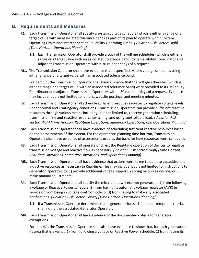
VAR-001-4.2 — Voltage and Reactive Control
Page 2 of 15
B. Requirements and Measures R1. Each Transmission Operator shall specify a system voltage schedule (which is either a range or a
target value with an associated tolerance band) as part of its plan to operate within System Operating Limits and Interconnection Reliability Operating Limits. [Violation Risk Factor: High] [Time Horizon: Operations Planning]
1.1. Each Transmission Operator shall provide a copy of the voltage schedules (which is either a range or a target value with an associated tolerance band) to its Reliability Coordinator and adjacent Transmission Operators within 30 calendar days of a request.
M1. The Transmission Operator shall have evidence that it specified system voltage schedules using either a range or a target value with an associated tolerance band.
For part 1.1, the Transmission Operator shall have evidence that the voltage schedules (which is either a range or a target value with an associated tolerance band) were provided to its Reliability Coordinator and adjacent Transmission Operators within 30 calendar days of a request. Evidence may include, but is not limited to, emails, website postings, and meeting minutes.
R2. Each Transmission Operator shall schedule sufficient reactive resources to regulate voltage levels under normal and Contingency conditions. Transmission Operators can provide sufficient reactive resources through various means including, but not limited to, reactive generation scheduling, transmission line and reactive resource switching, and using controllable load. [Violation Risk Factor: High] [Time Horizon: Real-time Operations, Same-day Operations, and Operations Planning]
M2. Each Transmission Operator shall have evidence of scheduling sufficient reactive resources based on their assessments of the system. For the operations planning time horizon, Transmission Operators shall have evidence of assessments used as the basis for how resources were scheduled.
R3. Each Transmission Operator shall operate or direct the Real-time operation of devices to regulate transmission voltage and reactive flow as necessary. [Violation Risk Factor: High] [Time Horizon: Real-time Operations, Same-day Operations, and Operations Planning]
M3. Each Transmission Operator shall have evidence that actions were taken to operate capacitive and inductive resources as necessary in Real-time. This may include, but is not limited to, instructions to Generator Operators to: 1) provide additional voltage support; 2) bring resources on-line; or 3) make manual adjustments.
R4. Each Transmission Operator shall specify the criteria that will exempt generators: 1) from following a voltage or Reactive Power schedule, 2) from having its automatic voltage regulator (AVR) in service or from being in voltage control mode, or 3) from having to make any associated notifications. [Violation Risk Factor: Lower] [Time Horizon: Operations Planning]
4.1 If a Transmission Operator determines that a generator has satisfied the exemption criteria, it shall notify the associated Generator Operator.
M4. Each Transmission Operator shall have evidence of the documented criteria for generator exemptions.
For part 4.1, the Transmission Operator shall also have evidence to show that, for each generator in its area that is exempt: 1) from following a voltage or Reactive Power schedule, 2) from having its

VAR-001-4.2 — Voltage and Reactive Control
Page 3 of 15
automatic voltage regulator (AVR) in service or from being in voltage control mode, or 3) from having to make any notifications, the associated Generator Operator was notified of this exemption.
R5. Each Transmission Operator shall specify a voltage or Reactive Power schedule (which is either a range or a target value with an associated tolerance band) at either the high voltage side or low voltage side of the generator step-up transformer at the Transmission Operator’s discretion. [Violation Risk Factor: Medium] [Time Horizon: Operations Planning]
5.1. The Transmission Operator shall provide the voltage or Reactive Power schedule (which is either a range or a target value with an associated tolerance band) to the associated Generator Operator and direct the Generator Operator to comply with the schedule in automatic voltage control mode (the AVR is in service and controlling voltage).
5.2. The Transmission Operator shall provide the Generator Operator with the notification requirements for deviations from the voltage or Reactive Power schedule (which is either a range or a target value with an associated tolerance band).
5.3. The Transmission Operator shall provide the criteria used to develop voltage schedules or Reactive Power schedule (which is either a range or a target value with an associated tolerance band) to the Generator Operator within 30 days of receiving a request.
M5. The Transmission Operator shall have evidence of a documented voltage or Reactive Power schedule (which is either a range or a target value with an associated tolerance band).
For part 5.1, the Transmission Operator shall have evidence it provided a voltage or Reactive Power schedule (which is either a range or a target value with an associated tolerance band) to the applicable Generator Operators, and that the Generator Operator was directed to comply with the schedule in automatic voltage control mode, unless exempted.
For part 5.2, the Transmission Operator shall have evidence it provided notification requirements for deviations from the voltage or Reactive Power schedule (which is either a range or a target value with an associated tolerance band). For part 5.3, the Transmission Operator shall have evidence it provided the criteria used to develop voltage schedules or Reactive Power schedule (which is either a range or a target value with an associated tolerance band) within 30 days of receiving a request by a Generator Operator.
R6. After consultation with the Generator Owner regarding necessary step-up transformer tap changes and the implementation schedule, the Transmission Operator shall provide documentation to the Generator Owner specifying the required tap changes, a timeframe for making the changes, and technical justification for these changes. [Violation Risk Factor: Lower] [Time Horizon: Operations Planning]
M6. The Transmission Operator shall have evidence that it provided documentation to the Generator Owner when a change was needed to a generating unit’s step-up transformer tap in accordance with the requirement and that it consulted with the Generator Owner.

VAR-001-4.2 — Voltage and Reactive Control
Page 4 of 15
C. Compliance 1. Compliance Monitoring Process:
1.1. Compliance Enforcement Authority:
As defined in the NERC Rules of Procedure, “Compliance Enforcement Authority” refers to NERC or the Regional Entity in their respective roles of monitoring and enforcing compliance with the NERC Reliability Standards.
1.2. Evidence Retention:
The following evidence retention periods identify the period of time a registered entity is required to retain specific evidence to demonstrate compliance. For instances in which the evidence retention period specified below is shorter than the time since the last audit, the Compliance Enforcement Authority may ask the registered entity to provide other evidence to show that it was compliant for the full time period since the last audit.
The Transmission Operator shall retain evidence for Measures M1 through M6 for 12 months. The Compliance Monitor shall retain any audit data for three years.
1.3. Compliance Monitoring and Assessment Processes:
“Compliance Monitoring and Assessment Processes” refers to the identification of the processes that will be used to evaluate data or information for the purpose of assessing performance or outcomes with the associated reliability standard.
1.4. Additional Compliance Information:
None

VAR-001-4.2 — Voltage and Reactive Control
Page 5 of 15
Table of Compliance Elements
R # Time Horizon VRF
Violation Severity Levels
Lower VSL Moderate VSL High VSL Severe VSL
R1 Operations Planning High N/A N/A N/A
The Transmission Operator does not specify a system voltage schedule (which is either a range or a target value with an associated tolerance band).
R2
Real-time Operations, Same-day Operations, and Operations Planning
High N/A N/A
The Transmission Operator does not schedule sufficient reactive resources as necessary to avoid violating an SOL.
The Transmission Operator does not schedule sufficient reactive resources as necessary to avoid violating an IROL.
R3
Real-time Operations, Same-day Operations, and Operations Planning
High N/A N/A
The Transmission Operator does not operate or direct any real-time operation of devices as necessary to avoid violating an SOL.
The Transmission Operator does not operate or direct any real-time operation of devices as necessary to avoid violating an IROL.

VAR-001-4.2 — Voltage and Reactive Control
Page 6 of 15
R # Time Horizon VRF
Violation Severity Levels
Lower VSL Moderate VSL High VSL Severe VSL
R4 Operations Planning Lower N/A N/A
The Transmission Operator has exemption criteria and notified the Generator Operator, but the Transmission Operator does not have evidence of the notification to the Generator Operator.
The Transmission Operator does not have exemption criteria.

VAR-001-4.2 — Voltage and Reactive Control
Page 7 of 15
R # Time Horizon VRF
Violation Severity Levels
Lower VSL Moderate VSL High VSL Severe VSL
R5 Operations Planning Medium N/A
The Transmission Operator does not provide the criteria for voltage or Reactive Power schedules (which is either a range or a target value with an associated tolerance band) after 30 days of a request.
The Transmission Operator does not provide voltage or Reactive Power schedules (which is either a range or a target value with an associated tolerance band) to all Generator Operators.
The Transmission Operator does not provide voltage or Reactive Power schedules (which is either a range or a target value with an associated tolerance band) to any Generator Operators. Or The Transmission Operator does not provide the Generator Operator with the notification requirements for deviations from the voltage or Reactive Power schedule (which is either a range or a target value with an associated tolerance band).

VAR-001-4.2 — Voltage and Reactive Control
Page 8 of 15
R # Time Horizon VRF
Violation Severity Levels
Lower VSL Moderate VSL High VSL Severe VSL
R6 Operations Planning Lower
The Transmission Operator does not provide either the technical justification or timeframe for changing generator step-up tap settings.
N/A N/A
The Transmission Operator does not provide the technical justification and the timeframe for changing generator step-up tap settings.
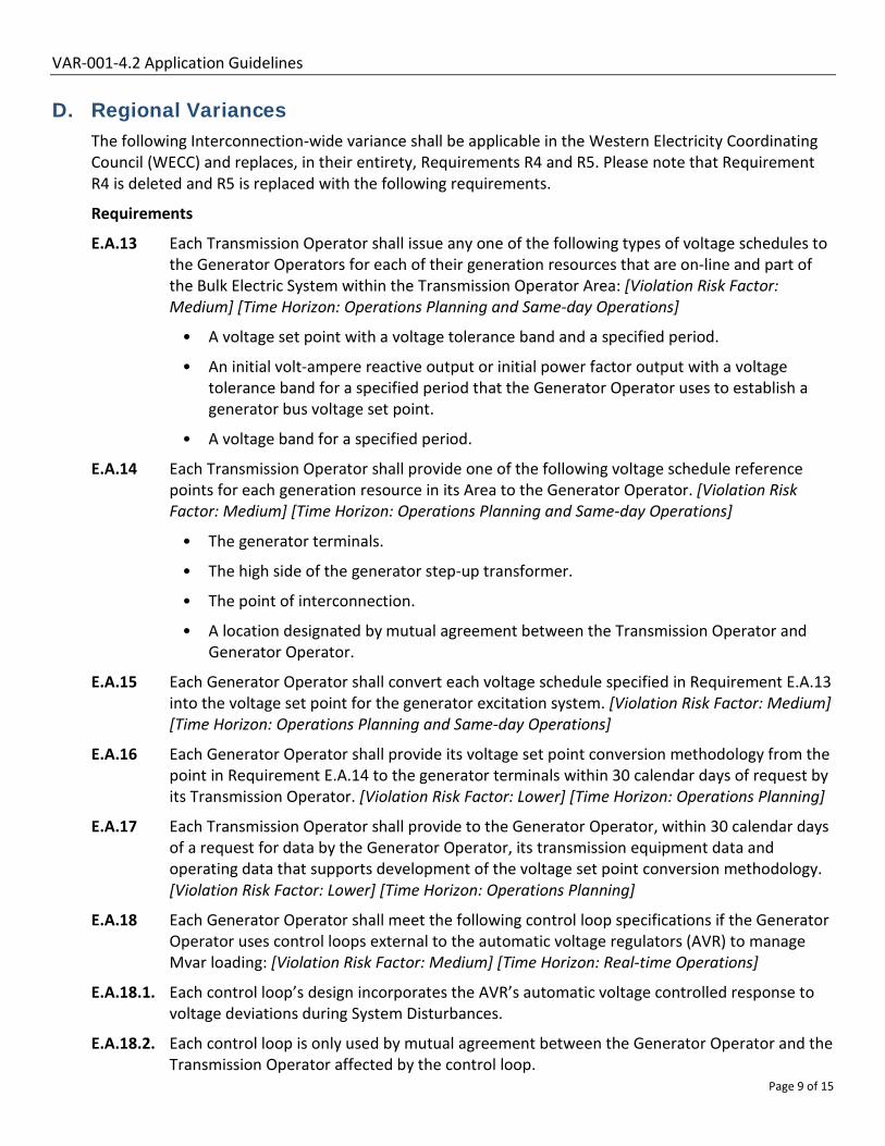
VAR-001-4.2 Application Guidelines
Page 9 of 15
D. Regional Variances The following Interconnection-wide variance shall be applicable in the Western Electricity Coordinating Council (WECC) and replaces, in their entirety, Requirements R4 and R5. Please note that Requirement R4 is deleted and R5 is replaced with the following requirements.
Requirements
E.A.13 Each Transmission Operator shall issue any one of the following types of voltage schedules to the Generator Operators for each of their generation resources that are on-line and part of the Bulk Electric System within the Transmission Operator Area: [Violation Risk Factor: Medium] [Time Horizon: Operations Planning and Same-day Operations]
• A voltage set point with a voltage tolerance band and a specified period.
• An initial volt-ampere reactive output or initial power factor output with a voltage tolerance band for a specified period that the Generator Operator uses to establish a generator bus voltage set point.
• A voltage band for a specified period.
E.A.14 Each Transmission Operator shall provide one of the following voltage schedule reference points for each generation resource in its Area to the Generator Operator. [Violation Risk Factor: Medium] [Time Horizon: Operations Planning and Same-day Operations]
• The generator terminals.
• The high side of the generator step-up transformer.
• The point of interconnection.
• A location designated by mutual agreement between the Transmission Operator and Generator Operator.
E.A.15 Each Generator Operator shall convert each voltage schedule specified in Requirement E.A.13 into the voltage set point for the generator excitation system. [Violation Risk Factor: Medium] [Time Horizon: Operations Planning and Same-day Operations]
E.A.16 Each Generator Operator shall provide its voltage set point conversion methodology from the point in Requirement E.A.14 to the generator terminals within 30 calendar days of request by its Transmission Operator. [Violation Risk Factor: Lower] [Time Horizon: Operations Planning]
E.A.17 Each Transmission Operator shall provide to the Generator Operator, within 30 calendar days of a request for data by the Generator Operator, its transmission equipment data and operating data that supports development of the voltage set point conversion methodology. [Violation Risk Factor: Lower] [Time Horizon: Operations Planning]
E.A.18 Each Generator Operator shall meet the following control loop specifications if the Generator Operator uses control loops external to the automatic voltage regulators (AVR) to manage Mvar loading: [Violation Risk Factor: Medium] [Time Horizon: Real-time Operations]
E.A.18.1. Each control loop’s design incorporates the AVR’s automatic voltage controlled response to voltage deviations during System Disturbances.
E.A.18.2. Each control loop is only used by mutual agreement between the Generator Operator and the Transmission Operator affected by the control loop.

VAR-001-4.2 Application Guidelines
Page 10 of 15
Measures1
M.E.A.13 Each Transmission Operator shall have and provide upon request, evidence that it provided the voltage schedules to the Generator Operator. Dated spreadsheets, reports, voice recordings, or other documentation containing the voltage schedule including set points, tolerance bands, and specified periods as required in Requirement E.A.13 are acceptable as evidence.
M.E.A.14 The Transmission Operator shall have and provide upon request, evidence that it provided one of the voltage schedule reference points in Requirement E.A.14 for each generation resource in its Area to the Generator Operator. Dated letters, e-mail, or other documentation that contains notification to the Generator Operator of the voltage schedule reference point for each generation resource are acceptable as evidence.
M.E.A.15 Each Generator Operator shall have and provide upon request, evidence that it converted a voltage schedule as described in Requirement E.A.13 into a voltage set point for the AVR. Dated spreadsheets, logs, reports, or other documentation are acceptable as evidence.
M.E.A.16 The Generator Operator shall have and provide upon request, evidence that within 30 calendar days of request by its Transmission Operator it provided its voltage set point conversion methodology from the point in Requirement E.A.14 to the generator terminals. Dated reports, spreadsheets, or other documentation are acceptable as evidence.
M.E.A.17 The Transmission Operator shall have and provide upon request, evidence that within 30 calendar days of request by its Generator Operator it provided data to support development of the voltage set point conversion methodology. Dated reports, spreadsheets, or other documentation are acceptable as evidence.
M.E.A.18 If the Generator Operator uses outside control loops to manage Mvar loading, the Generator Operator shall have and provide upon request, evidence that it met the control loop specifications in sub-parts E.A.18.1 through E.A.18.2. Design specifications with identified agreed-upon control loops, system reports, or other dated documentation are acceptable as evidence.
1 The number for each measure corresponds with the number for each requirement, i.e. M.E.A.13 means the measure for Requirement E.A.13.
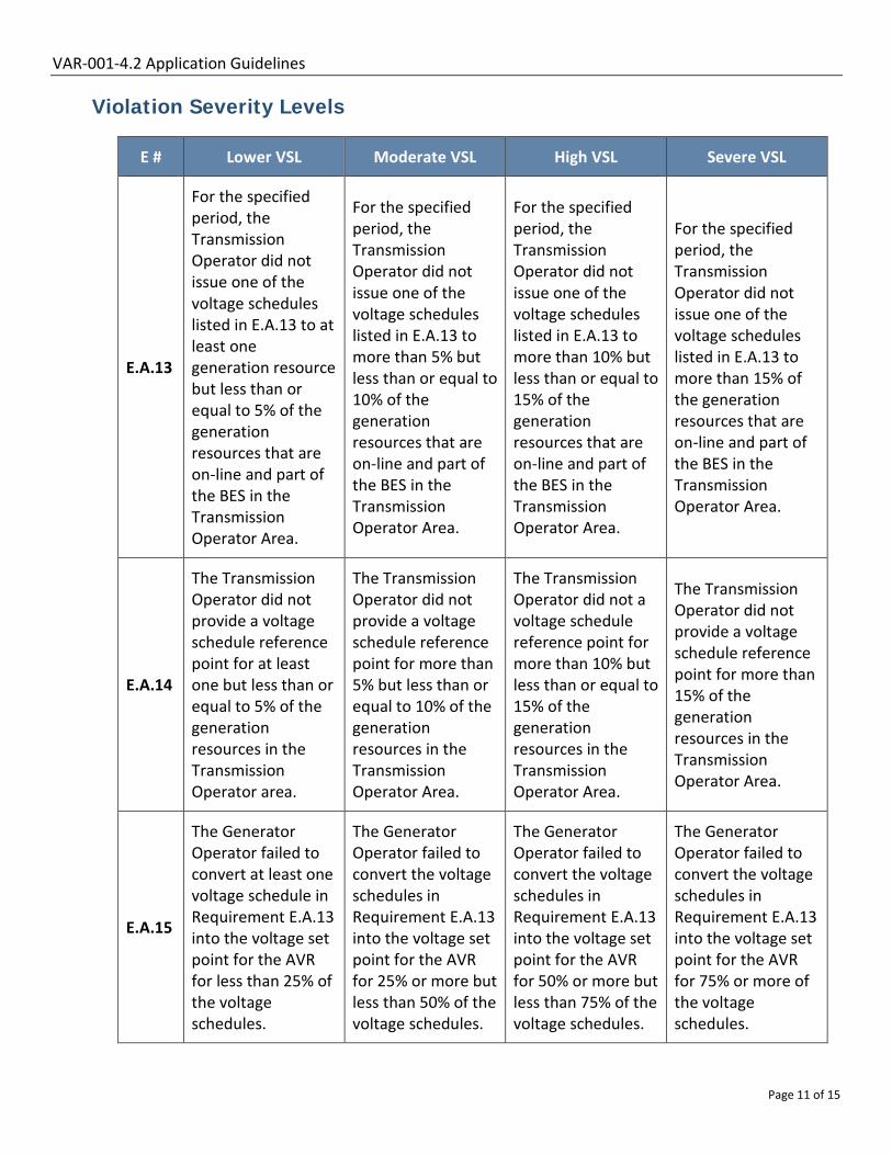
VAR-001-4.2 Application Guidelines
Page 11 of 15
Violation Severity Levels
E # Lower VSL Moderate VSL High VSL Severe VSL
E.A.13
For the specified period, the Transmission Operator did not issue one of the voltage schedules listed in E.A.13 to at least one generation resource but less than or equal to 5% of the generation resources that are on-line and part of the BES in the Transmission Operator Area.
For the specified period, the Transmission Operator did not issue one of the voltage schedules listed in E.A.13 to more than 5% but less than or equal to 10% of the generation resources that are on-line and part of the BES in the Transmission Operator Area.
For the specified period, the Transmission Operator did not issue one of the voltage schedules listed in E.A.13 to more than 10% but less than or equal to 15% of the generation resources that are on-line and part of the BES in the Transmission Operator Area.
For the specified period, the Transmission Operator did not issue one of the voltage schedules listed in E.A.13 to more than 15% of the generation resources that are on-line and part of the BES in the Transmission Operator Area.
E.A.14
The Transmission Operator did not provide a voltage schedule reference point for at least one but less than or equal to 5% of the generation resources in the Transmission Operator area.
The Transmission Operator did not provide a voltage schedule reference point for more than 5% but less than or equal to 10% of the generation resources in the Transmission Operator Area.
The Transmission Operator did not a voltage schedule reference point for more than 10% but less than or equal to 15% of the generation resources in the Transmission Operator Area.
The Transmission Operator did not provide a voltage schedule reference point for more than 15% of the generation resources in the Transmission Operator Area.
E.A.15
The Generator Operator failed to convert at least one voltage schedule in Requirement E.A.13 into the voltage set point for the AVR for less than 25% of the voltage schedules.
The Generator Operator failed to convert the voltage schedules in Requirement E.A.13 into the voltage set point for the AVR for 25% or more but less than 50% of the voltage schedules.
The Generator Operator failed to convert the voltage schedules in Requirement E.A.13 into the voltage set point for the AVR for 50% or more but less than 75% of the voltage schedules.
The Generator Operator failed to convert the voltage schedules in Requirement E.A.13 into the voltage set point for the AVR for 75% or more of the voltage schedules.

VAR-001-4.2 Application Guidelines
Page 12 of 15
E # Lower VSL Moderate VSL High VSL Severe VSL
E.A.16
The Generator Operator provided its voltage set point conversion methodology greater than 30 days but less than or equal to 60 days of a request by the Transmission Operator.
The Generator Operator provided its voltage set point conversion methodology greater than 60 days but less than or equal to 90 days of a request by the Transmission Operator.
The Generator Operator provided its voltage set point conversion methodology greater than 90 days but less than or equal to 120 days of a request by the Transmission Operator.
The Generator Operator did not provide its voltage set point conversion methodology within 120 days of a request by the Transmission Operator.
E.A.17
The Transmission Operator provided its data to support development of the voltage set point conversion methodology than 30 days but less than or equal to 60 days of a request by the Generator Operator.
The Transmission Operator provided its data to support development of the voltage set point conversion methodology greater than 60 days but less than or equal to 90 days of a request by the Generator. Operator.
The Transmission Operator provided its data to support development of the voltage set point conversion methodology greater than 90 days but less than or equal to 120 days of a request by the Generator. Operator.
The Transmission Operator did not provide its data to support development of the voltage set point conversion methodology within 120 days of a request by the Generator Operator.
E.A.18 N/A
The Generator Operator did not meet the control loop specifications in EA18.2 when the Generator Operator uses control loop external to the AVR to manage Mvar loading.
The Generator Operator did not meet the control loop specifications in EA18.1 when the Generator Operator uses control loop external to the AVR to manage Mvar loading.
The Generator Operator did not meet the control loop specifications in EA18.1 through EA18.2 when the Generator Operator uses control loop external to the AVR to manage Mvar loading.
E. Interpretations
None

VAR-001-4.2 Application Guidelines
Page 13 of 15
F. Associated Documents
None.
Version History
Version Date Action Change Tracking
0 April 1, 2005 Effective Date New
1 August 2, 2006 BOT Adoption Revised
1 June 18, 2007 FERC approved Version 1 of the standard. Revised
1 July 3, 2007 Added “Generator Owners” and “Generator Operators” to Applicability section.
Errata
1 August 23, 2007 Removed “Generator Owners” and “Generator Operators” to Applicability section.
Errata
2 August 5, 2010 Adopted by NERC Board of Trustees; Modified to address Order No. 693 Directives contained in paragraphs 1858 and 1879.
Revised
2 January, 10 2011 FERC issued letter order approving the addition of LSEs and Controllable Load to the standard.
Revised
3 May 9, 2012 Adopted by NERC Board of Trustees; Modified to add a WECC region variance
Revised
3 June 20, 2013 FERC issued order approving VAR-001-3 Revised
3 November 21, 2013
R5 and associated elements approved by FERC for retirement as part of the Paragraph 81 project (Project 2013-02)
Revised
4 February 6, 2014 Adopted by NERC Board of Trustees Revised
4 August 1, 2014 FERC issued letter order issued approving VAR-001-4
4.1 August 25, 2015 Added “or” to Requirement R5, 5.3 to read: schedules or Reactive Power
Errata
4.1 November 13, 2015
FERC Letter Order approved errata to VAR-001-4.1. Docket RD15-6-000
Errata
4.2 June 14, 2017 Project 2016-EPR-02 errata recommendations Errata 4.2 August 10, 2017 Adopted by NERC Board of Trustees Errata 4.2 September 26,
2017 FERC Letter Order issued approving VAR-001-4.2 Docket No. RD17-7-000.
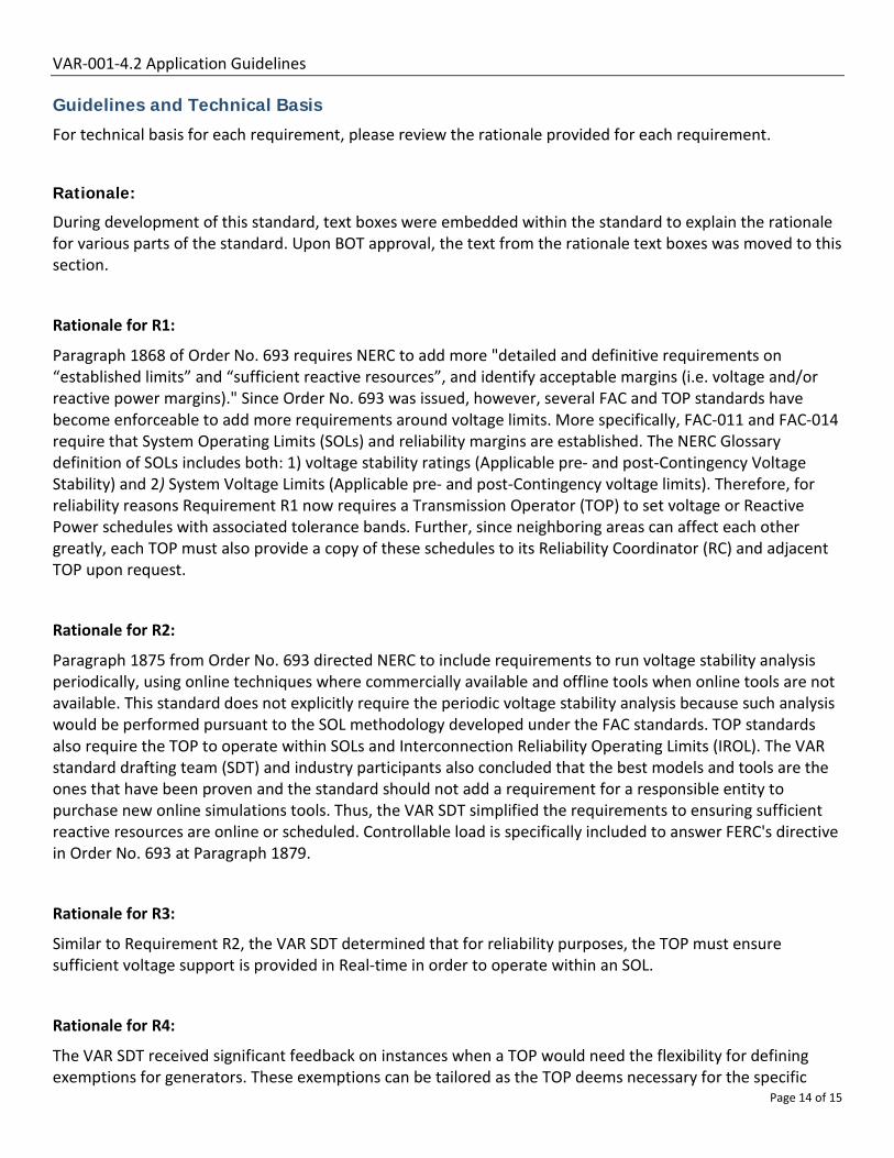
VAR-001-4.2 Application Guidelines
Page 14 of 15
Guidelines and Technical Basis
For technical basis for each requirement, please review the rationale provided for each requirement.
Rationale:
During development of this standard, text boxes were embedded within the standard to explain the rationale for various parts of the standard. Upon BOT approval, the text from the rationale text boxes was moved to this section.
Rationale for R1:
Paragraph 1868 of Order No. 693 requires NERC to add more "detailed and definitive requirements on “established limits” and “sufficient reactive resources”, and identify acceptable margins (i.e. voltage and/or reactive power margins)." Since Order No. 693 was issued, however, several FAC and TOP standards have become enforceable to add more requirements around voltage limits. More specifically, FAC-011 and FAC-014 require that System Operating Limits (SOLs) and reliability margins are established. The NERC Glossary definition of SOLs includes both: 1) voltage stability ratings (Applicable pre- and post-Contingency Voltage Stability) and 2) System Voltage Limits (Applicable pre- and post-Contingency voltage limits). Therefore, for reliability reasons Requirement R1 now requires a Transmission Operator (TOP) to set voltage or Reactive Power schedules with associated tolerance bands. Further, since neighboring areas can affect each other greatly, each TOP must also provide a copy of these schedules to its Reliability Coordinator (RC) and adjacent TOP upon request.
Rationale for R2:
Paragraph 1875 from Order No. 693 directed NERC to include requirements to run voltage stability analysis periodically, using online techniques where commercially available and offline tools when online tools are not available. This standard does not explicitly require the periodic voltage stability analysis because such analysis would be performed pursuant to the SOL methodology developed under the FAC standards. TOP standards also require the TOP to operate within SOLs and Interconnection Reliability Operating Limits (IROL). The VAR standard drafting team (SDT) and industry participants also concluded that the best models and tools are the ones that have been proven and the standard should not add a requirement for a responsible entity to purchase new online simulations tools. Thus, the VAR SDT simplified the requirements to ensuring sufficient reactive resources are online or scheduled. Controllable load is specifically included to answer FERC's directive in Order No. 693 at Paragraph 1879.
Rationale for R3:
Similar to Requirement R2, the VAR SDT determined that for reliability purposes, the TOP must ensure sufficient voltage support is provided in Real-time in order to operate within an SOL.
Rationale for R4:
The VAR SDT received significant feedback on instances when a TOP would need the flexibility for defining exemptions for generators. These exemptions can be tailored as the TOP deems necessary for the specific

VAR-001-4.2 Application Guidelines
Page 15 of 15
area’s needs. The goal of this requirement is to provide a TOP the ability to exempt a Generator Operator (GOP) from: 1) a voltage or Reactive Power schedule, 2) a setting on the AVR, or 3) any VAR-002 notifications based on the TOP’s criteria. Feedback from the industry detailed many system events that would require these types of exemptions which included, but are not limited to: 1) maintenance during shoulder months, 2) scenarios where two units are located within close proximity and both cannot be in voltage control mode, and 3) large system voltage swings where it would harm reliability if all GOP were to notify their respective TOP of deviations at one time. Also, in an effort to improve the requirement, the sub-requirements containing an exemption list were removed from the currently enforceable standard because this created more compliance issues with regard to how often the list would be updated and maintained.
Rationale for R5:
The new requirement provides transparency regarding the criteria used by the TOP to establish the voltage schedule. This requirement also provides a vehicle for the TOP to use appropriate granularity when setting notification requirements for deviation from the voltage or Reactive Power schedule. Additionally, this requirement provides clarity regarding a “tolerance band” as specified in the voltage schedule and the control dead-band in the generator’s excitation system.
Voltage schedule tolerances are the bandwidth that accompanies the voltage target in a voltage schedule, should reflect the anticipated fluctuation in voltage at the Generation Operator’s facility during normal operations, and be based on the TOP’s assessment of N-1 and credible N-2 system contingencies. The voltage schedule’s bandwidth should not be confused with the control dead-band that is programmed into a Generation Operator’s automatic voltage regulator’s control system, which should be adjusting the AVR prior to reaching either end of the voltage schedule’s bandwidth.
Rationale for R6:
Although tap settings are first established prior to interconnection, this requirement could not be deleted because no other standard addresses when a tap setting must be adjusted. If the tap setting is not properly set, then the amount of VARs produced by a unit can be affected.

Standard Requirement Effective Date of Standard
Phased In Implementation Date (if applicable)
Inactive Date
VAR-001-4.2 All 09/26/2017
Printed On: November 29, 2017, 09:16 AM
Effective Date of Standard: VAR-001-4.2 — Voltage and Reactive Control
* FOR INFORMATIONAL PURPOSES ONLY *
United States

Reliability Standard VAR-002-4.1

VAR-002-4.1 — Generator Operation for Maintaining Network Voltage Schedules
1
A. Introduction 1. Title: Generator Operation for Maintaining Network Voltage Schedules
2. Number: VAR-002-4.1
3. Purpose: To ensure generators provide reactive support and voltage control, within generating Facility capabilities, in order to protect equipment and maintain reliable operation of the Interconnection.
4. Applicability:
4.1. Generator Operator
4.2. Generator Owner
5. Effective Dates
See Implementation Plan.
B. Requirements and Measures R1. The Generator Operator shall operate each generator connected to the interconnected
transmission system in the automatic voltage control mode (with its automatic voltage regulator (AVR) in service and controlling voltage) or in a different control mode as instructed by the Transmission Operator unless: 1) the generator is exempted by the Transmission Operator, or 2) the Generator Operator has notified the Transmission Operator of one of the following: [Violation Risk Factor: Medium] [Time Horizon: Real-time Operations]
• That the generator is being operated in start-up,1 shutdown,2 or testing mode pursuant to a Real-time communication or a procedure that was previously provided to the Transmission Operator; or
• That the generator is not being operated in automatic voltage control mode or in the control mode that was instructed by the Transmission Operator for a reason other than start-up, shutdown, or testing.
M1. The Generator Operator shall have evidence to show that it notified its associated Transmission Operator any time it failed to operate a generator in the automatic voltage control mode or in a different control mode as specified in Requirement R1. If a generator is being started up or shut down with the automatic voltage control off, or is being tested, and no notification of the AVR status is made to the Transmission Operator, the Generator Operator will have evidence that it notified the Transmission Operator of its procedure for placing the unit into automatic voltage control mode as required in Requirement R1. Such evidence may include, but is not limited to, dated evidence of transmittal of the procedure such as an electronic message or a transmittal letter with the procedure included or attached. If a generator is exempted, the Generator Operator shall also have evidence that the generator is exempted from being in automatic voltage control mode (with its AVR in service and controlling voltage).
1 Start-up is deemed to have ended when the generator is ramped up to its minimum continuously sustainable load and the generator is prepared for continuous operation. 2 Shutdown is deemed to begin when the generator is ramped down to its minimum continuously sustainable load and the generator is prepared to go offline.
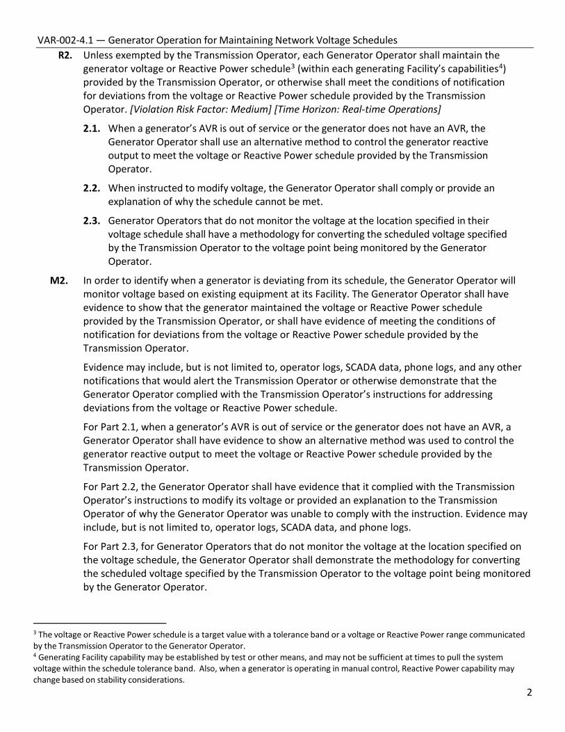
VAR-002-4.1 — Generator Operation for Maintaining Network Voltage Schedules
2
R2. Unless exempted by the Transmission Operator, each Generator Operator shall maintain the generator voltage or Reactive Power schedule3 (within each generating Facility’s capabilities4) provided by the Transmission Operator, or otherwise shall meet the conditions of notification for deviations from the voltage or Reactive Power schedule provided by the Transmission Operator. [Violation Risk Factor: Medium] [Time Horizon: Real-time Operations]
2.1. When a generator’s AVR is out of service or the generator does not have an AVR, the Generator Operator shall use an alternative method to control the generator reactive output to meet the voltage or Reactive Power schedule provided by the Transmission Operator.
2.2. When instructed to modify voltage, the Generator Operator shall comply or provide an explanation of why the schedule cannot be met.
2.3. Generator Operators that do not monitor the voltage at the location specified in their voltage schedule shall have a methodology for converting the scheduled voltage specified by the Transmission Operator to the voltage point being monitored by the Generator Operator.
M2. In order to identify when a generator is deviating from its schedule, the Generator Operator will monitor voltage based on existing equipment at its Facility. The Generator Operator shall have evidence to show that the generator maintained the voltage or Reactive Power schedule provided by the Transmission Operator, or shall have evidence of meeting the conditions of notification for deviations from the voltage or Reactive Power schedule provided by the Transmission Operator.
Evidence may include, but is not limited to, operator logs, SCADA data, phone logs, and any other notifications that would alert the Transmission Operator or otherwise demonstrate that the Generator Operator complied with the Transmission Operator’s instructions for addressing deviations from the voltage or Reactive Power schedule.
For Part 2.1, when a generator’s AVR is out of service or the generator does not have an AVR, a Generator Operator shall have evidence to show an alternative method was used to control the generator reactive output to meet the voltage or Reactive Power schedule provided by the Transmission Operator.
For Part 2.2, the Generator Operator shall have evidence that it complied with the Transmission Operator’s instructions to modify its voltage or provided an explanation to the Transmission Operator of why the Generator Operator was unable to comply with the instruction. Evidence may include, but is not limited to, operator logs, SCADA data, and phone logs.
For Part 2.3, for Generator Operators that do not monitor the voltage at the location specified on the voltage schedule, the Generator Operator shall demonstrate the methodology for converting the scheduled voltage specified by the Transmission Operator to the voltage point being monitored by the Generator Operator.
3 The voltage or Reactive Power schedule is a target value with a tolerance band or a voltage or Reactive Power range communicated by the Transmission Operator to the Generator Operator. 4 Generating Facility capability may be established by test or other means, and may not be sufficient at times to pull the system voltage within the schedule tolerance band. Also, when a generator is operating in manual control, Reactive Power capability may change based on stability considerations.

VAR-002-4.1 — Generator Operation for Maintaining Network Voltage Schedules
3
R3. Each Generator Operator shall notify its associated Transmission Operator of a status change on the AVR, power system stabilizer, or alternative voltage controlling device within 30 minutes of the change. If the status has been restored within 30 minutes of such change, then the Generator Operator is not required to notify the Transmission Operator of the status change. [Violation Risk Factor: Medium] [Time Horizon: Real-time Operations]
M3. The Generator Operator shall have evidence it notified its associated Transmission Operator within 30 minutes of any status change identified in Requirement R3. If the status has been restored within the first 30 minutes, no notification is necessary.
R4. Each Generator Operator shall notify its associated Transmission Operator within 30 minutes of becoming aware of a change in reactive capability due to factors other than a status change described in Requirement R3. If the capability has been restored within 30 minutes of the Generator Operator becoming aware of such change, then the Generator Operator is not required to notify the Transmission Operator of the change in reactive capability. [Violation Risk Factor: Medium] [Time Horizon: Real-time Operations]
• Reporting of status or capability changes as stated in Requirement R4 is not applicable to the individual generating units of dispersed power producing resources identified through Inclusion I4 of the Bulk Electric System definition.
M4. The Generator Operator shall have evidence it notified its associated Transmission Operator within 30 minutes of becoming aware of a change in reactive capability in accordance with Requirement R4. If the capability has been restored within the first 30 minutes, no notification is necessary.
R5. The Generator Owner shall provide the following to its associated Transmission Operator and Transmission Planner within 30 calendar days of a request. [Violation Risk Factor: Lower] [Time Horizon: Real-time Operations]
5.1. For generator step-up and auxiliary transformers5 with primary voltages equal to or greater than the generator terminal voltage:
5.1.1. Tap settings.
5.1.2. Available fixed tap ranges.
5.1.3. Impedance data.
M5. The Generator Owner shall have evidence it provided its associated Transmission Operator and Transmission Planner with information on its step-up and auxiliary transformers as required in Requirement R5, Part 5.1.1 through Part 5.1.3 within 30 calendar days.
5 For dispersed power producing resources identified through Inclusion I4 of the Bulk Electric System definition, this requirement applies only to those transformers that have at least one winding at a voltage of 100 kV or above.

VAR-002-4.1 — Generator Operation for Maintaining Network Voltage Schedules
4
R6. After consultation with the Transmission Operator regarding necessary step-up transformer tap changes, the Generator Owner shall ensure that transformer tap positions are changed according to the specifications provided by the Transmission Operator, unless such action would violate safety, an equipment rating, a regulatory requirement, or a statutory requirement. [Violation Risk Factor: Lower] [Time Horizon: Real-time Operations]
6.1. If the Generator Owner cannot comply with the Transmission Operator’s specifications, the Generator Owner shall notify the Transmission Operator and shall provide the technical justification.
M6. The Generator Owner shall have evidence that its step-up transformer taps were modified per the Transmission Operator’s documentation in accordance with Requirement R6. The Generator Owner shall have evidence that it notified its associated Transmission Operator when it could not comply with the Transmission Operator’s step-up transformer tap specifications in accordance with Requirement R6, Part 6.1.
VAR-002-4.1 — Generator Operation for Maintaining Network Voltage Schedules
5
C. Compliance 1. Compliance Monitoring Process:
1.1. Compliance Enforcement Authority:
As defined in the NERC Rules of Procedure, “Compliance Enforcement Authority” refers to NERC or the Regional Entity in their respective roles of monitoring and enforcing compliance with the NERC Reliability Standards.
1.2. Evidence Retention:
The following evidence retention periods identify the period of time an entity is required to retain specific evidence to demonstrate compliance. For instances where the evidence retention period specified below is shorter than the time since the last audit, the Compliance Enforcement Authority may ask an entity to provide other evidence to show that it was compliant for the full time period since the last audit.
The Generator Owner shall keep its latest version of documentation on its step-up and auxiliary transformers. The Generator Operator shall maintain all other evidence for the current and previous calendar year.
The Compliance Monitor shall retain any audit data for three years.
1.3. Compliance Monitoring and Assessment Processes:
“Compliance Monitoring and Assessment Processes” refers to the identification of the processes that will be used to evaluate data or information for the purpose of assessing performance or outcomes with the associated reliability standard.
1.4. Additional Compliance Information:
None.

VAR-002-4.1 — Generator Operation for Maintaining Network Voltage Schedules
6
Table of Compliance Elements
R # Time
Horizon VRF
Violation Severity Levels
Lower VSL Moderate VSL High VSL Severe VSL
R1 Real-time Operations Medium N/A N/A N/A
Unless exempted, the Generator Operator did not operate each generator connected to the interconnected transmission system in the automatic voltage control mode or in a different control mode as instructed by the Transmission Operator, and failed to provide the required notifications to Transmission Operator as identified in Requirement R1.

VAR-002-4.1 — Generator Operation for Maintaining Network Voltage Schedules
7
R # Time
Horizon VRF
Violation Severity Levels
Lower VSL Moderate VSL High VSL Severe VSL
R2 Real-time Operations Medium N/A N/A
The Generator Operator did not have a conversion methodology when it monitors voltage at a location different from the schedule provided by the Transmission Operator.
The Generator Operator did not maintain the voltage or Reactive Power schedule as instructed by the Transmission Operator and did not make the necessary notifications required by the Transmission Operator.
OR
The Generator Operator did not have an operating AVR, and the responsible entity did not use an alternative method for controlling voltage.
OR
The Generator Operator did not modify voltage when directed, and the responsible entity did not provide any explanation.
R3 Real-time Operations Medium N/A N/A N/A
The Generator Operator did not make the required notification within 30 minutes of the status change.

VAR-002-4.1 — Generator Operation for Maintaining Network Voltage Schedules
8
R # Time
Horizon VRF
Violation Severity Levels
Lower VSL Moderate VSL High VSL Severe VSL
R4 Real-time Operations Medium N/A N/A N/A
The Generator Operator did not make the required notification within 30 minutes of becoming aware of the capability change.
R5 Real-time Operations Lower N/A N/A
The Generator Owner failed to provide its associated Transmission Operator and Transmission Planner one of the types of data specified in Requirement R5 Parts 5.1.1, 5.1.2, and 5.1.3.
The Generator Owner failed to provide to its associated Transmission Operator and Transmission Planner two or more of the types of data specified in Requirement R5 Parts 5.1.1, 5.1.2, and 5.1.3.
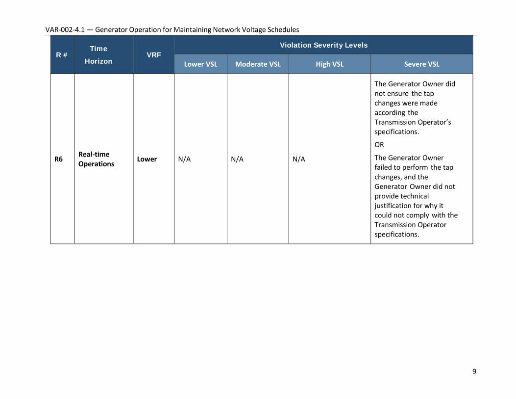
VAR-002-4.1 — Generator Operation for Maintaining Network Voltage Schedules
9
R # Time
Horizon VRF
Violation Severity Levels
Lower VSL Moderate VSL High VSL Severe VSL
R6 Real-time Operations Lower N/A N/A N/A
The Generator Owner did not ensure the tap changes were made according the Transmission Operator’s specifications.
OR
The Generator Owner failed to perform the tap changes, and the Generator Owner did not provide technical justification for why it could not comply with the Transmission Operator specifications.

VAR-002-4.1 — Generator Operation for Maintaining Network Voltage Schedules
13
D. Regional Variances
None.
E. Interpretations
None.
F. Associated Documents
None. Version History
Version Date Action Change Tracking
1 5/1/2006 Added “(R2)” to the end of levels on non-compliance 2.1.2, 2.2.2, 2.3.2, and2.4.3.
July 5, 2006
1a 12/19/2007 Added Appendix 1 – Interpretation of R1 and R2 approved by BOT on August 1, 2007
Revised
1a 1/16/2007 In Section A.2., Added “a” to end of standard number. Section F: added “1.”; and added date.
Errata
1.1a 10/29/2008 BOT adopted errata changes; updated version number to “1.1a” Errata
1.1b 3/3/2009 Added Appendix 2 – Interpretation of VAR-002-1.1a approved by BOT on February 10, 2009
Revised
2b 4/16/2013
Revised R1 to address an Interpretation Request. Also added previously approved VRFs, Time Horizons and VSLs. Revised R2 to address consistency issue with VAR-001-2, R4. FERC Order issued approving VAR-002-2b.
Revised
3 5/5/2014 Revised under Project 2013-04 to address outstanding Order 693 directives.
Revised
3 5/7/2014 Adopted by NERC Board of Trustees
3 8/1/2014 Approved by FERC in docket RD14-11-000
4 8/27/2014 Revised under Project 2014-01 to clarify applicability of Requirements to Revised

VAR-002-4.1 — Generator Operation for Maintaining Network Voltage Schedules
14
BES dispersed power producing resources.
4 11/13/2014 Adopted by NERC Board of Trustees
4 5/29/2015 FERC Letter Order in Docket No. RD15-3-000 approving VAR-002-4
4.1 June 14, 2017 Project 2016-EPR-02 errata recommendations Errata
4.1 August 10, 2017 Adopted by the NERC Board of Trustees Errata
4.1 September 26, 2017
FERC Letter Order issued approving VAR-002-4.1 RD17-7-000

VAR-002-4.1 Application Guidelines
15
Guidelines and Technical Basis Rationale:
During development of this standard, text boxes were embedded within the standard to explain the rationale for various parts of the standard. Upon BOT approval, the text from the rationale text boxes was moved to this section.
Rationale for R1:
This requirement has been maintained due to the importance of running a unit with its automatic voltage regulator (AVR) in service and in either voltage controlling mode or the mode instructed by the TOP. However, the requirement has been modified to allow for testing, and the measure has been updated to include some of the evidence that can be used for compliance purposes.
Rationale for R2:
Requirement R2 details how a Generator Operator (GOP) operates its generator(s) to provide voltage support and when the GOP is expected to notify the Transmission Operator (TOP). In an effort to remove prescriptive notification requirements for the entire continent, the VAR-002-3 standard drafting team (SDT) opted to allow each TOP to determine the notification requirements for each of its respective GOPs based on system requirements. Additionally, a new Part 2.3 has been added to detail that each GOP may monitor voltage by using its existing facility equipment.
Conversion Methodology: There are many ways to convert the voltage schedule from one voltage level to another. Some entities may choose to develop voltage regulation curves for their transformers; others may choose to do a straight ratio conversion; others may choose an entirely different methodology. All of these methods have technical challenges, but the studies performed by the TOP, which consider N-1 and credible N-2 contingencies, should compensate for the error introduced by these methodologies, and the TOP possesses the authority to direct the GOP to modify its output if its performance is not satisfactory. During a significant system event, such as a voltage collapse, even a generation unit in automatic voltage control that controls based on the low-side of the generator step-up transformer should see the event on the low-side of the generator step-up transformer and respond accordingly.
Voltage Schedule Tolerances: The bandwidth that accompanies the voltage target in a voltage schedule should reflect the anticipated fluctuation in voltage at the GOP’s Facility during normal operations and be based on the TOP’s assessment of N-1 and credible N-2 system contingencies. The voltage schedule’s bandwidth should not be confused with the control dead-band that is programmed into a GOP’s AVR control system, which should be adjusting the AVR prior to reaching either end of the voltage schedule’s bandwidth.
Rationale for R3:
This requirement has been modified to limit the notifications required when an AVR goes out of service and quickly comes back in service. Notifications of this type of status change provide little to no benefit to reliability. Thirty (30) minutes have been built into the requirement to allow a GOP time to resolve an issue before having to notify the TOP of a status change. The requirement has

VAR-002-4.1 Application Guidelines
16
also been amended to remove the sub-requirement to provide an estimate for the expected duration of the status change.
Rationale for R4:
This requirement has been bifurcated from the prior version VAR-002-2b Requirement R3. This requirement allows GOPs to report reactive capability changes after they are made aware of the change. The current standard requires notification as soon as the change occurs, but many GOPs are not aware of a reactive capability change until it has taken place.
Rationale for Exclusion in R4:
VAR-002 addresses control and management of reactive resources and provides voltage control where it has an impact on the BES. For dispersed power producing resources as identified in Inclusion I4, Requirement R4 should not apply at the individual generator level due to the unique characteristics and small scale of individual dispersed power producing resources. In addition, other standards such as proposed TOP-003 require the Generator Operator to provide Real-time data as directed by the TOP.
Rationale for R5:
This requirement and corresponding measure have been maintained due to the importance of having accurate tap settings. If the tap setting is not properly set, then the VARs available from that unit can be affected. The prior version of VAR-002-2b, Requirement R4.1.4 (the +/- voltage range with step-change in % for load-tap changing transformers) has been removed. The percentage information was not needed because the tap settings, ranges and impedance are required. Those inputs can be used to calculate the step-change percentage if needed.
Rationale for Exclusion in R5:
The Transmission Operator and Transmission Planner only need to review tap settings, available fixed tap ranges, impedance data and the +/- voltage range with step-change in % for load-tap changing transformers on main generator step-up unit transformers which connect dispersed power producing resources identified through Inclusion I4 of the Bulk Electric System definition to their transmission system. The dispersed power producing resources individual generator transformers are not intended, designed or installed to improve voltage performance at the point of interconnection. In addition, the dispersed power producing resources individual generator transformers have traditionally been excluded from Requirement R4 and R5 of VAR- 002-2b (similar requirements are R5 and R6 for VAR-002-3), as they are not used to improve voltage performance at the point of interconnection.
Rationale for R6:
This requirement and corresponding measure have been maintained due to the importance of having accurate tap settings. If the tap setting is not properly set, then the VARs available from that unit can be affected.

Standard Requirement Effective Date of Standard
Phased In Implementation Date (if applicable)
Inactive Date
VAR-002-4.1 All 09/26/2017
Printed On: November 29, 2017, 09:11 AM
Effective Date of Standard: VAR-002-4.1 — Generator Operation for Maintaining Network Voltage Schedules
* FOR INFORMATIONAL PURPOSES ONLY *
United States

Exhibit B: List of Currently Effective NERC Reliability Standards in Third Quarter 2017

Exhibit B: List of Currently Effective NERC Reliability Standards in Third Quarter 2017
Resource and Demand Balancing (BAL)
BAL-001-2 Real Power Balancing Control Performance
BAL-001-TRE-1 Primary Frequency Response in the ERCOT Region
BAL-002-1 Disturbance Control Performance
BAL-002-WECC-2a Contingency Reserve
BAL-003-1.1 Frequency Response and Frequency Bias Setting
BAL-004-0 Time Error Correction
BAL-004-WECC-02 Automatic Time Error Correction (ATEC)
BAL-005-0.2b Automatic Generation Control
BAL-006-2 Inadvertent Interchange
BAL-502-RFC-02 Planning Resource Adequacy Analysis, Assessment and Documentation
Communications (COM )
COM-001-3 Communications
COM-002-4 Operating Personnel Communications Protocols
Critical Infrastructure Protection (CIP)
CIP-002-5.1a Cyber Security — BES Cyber System Categorization
CIP-003-6 Cyber Security — Security Management Controls
CIP-004-6 Cyber Security — Personnel & Training
CIP-005-5 Cyber Security — Electronic Security Perimeter(s)
CIP-006-6 Cyber Security — Physical Security of BES Cyber Systems
CIP-007-6 Cyber Security — System Security Management
CIP-008-5 Cyber Security — Incident Reporting and Response Planning
CIP-009-6 Cyber Security — Recovery Plans for BES Cyber Systems
CIP-010-2 Cyber Security — Configuration Change Management and Vulnerability Assessments
CIP-011-2 Cyber Security — Information Protection
CIP-014-2 Physical Security
Emergency Preparedness and Operations (EOP)
EOP-004-3 Event Reporting
EOP-005-2 System Restoration from Blackstart Resources

EOP-006-2 System Restoration Coordination
EOP-008-1 Loss of Control Center Functionality
EOP-010-1 Geomagnetic Disturbance Operations
EOP-011-1 Emergency Operations
Facilities Design, Connections, and Maintenance (FAC )
FAC-001-2 Facility Interconnection Requirements
FAC-002-2 Facility Interconnection Studies
FAC-003-4 Transmission Vegetation Management
FAC-008-3 Facility Ratings
FAC-010-3 System Operating Limits Methodology for the Planning Horizon
FAC-011-3 System Operating Limits Methodology for the Operations Horizon
FAC-013-2 Assessment of Transfer Capability for the Near-Term Transmission Planning Horizon
FAC-014-2 Establish and Communicate System Operating Limits
FAC-501-WECC-1 Transmission Maintenance
Interchange Scheduling and Coordination (INT)
INT-004-3.1 Dynamic Transfers
INT-006-4 Evaluation of Interchange Transactions
INT-009-2.1 Implementation of Interchange
INT-010-2.1 Interchange Initiation and Modification for Reliability
Interconnection Reliability Operations and Coordination (IRO)
IRO-001-4 Reliability Coordination – Responsibilities
IRO-002-5 Reliability Coordination – Monitoring and Analysis
IRO-006-5 Reliability Coordination — Transmission Loading Relief (TLR)
IRO-006-EAST-2 Transmission Loading Relief Procedure for the Eastern Interconnection
IRO-006-TRE-1 IROL and SOL Mitigation in the ERCOT Region
IRO-006-WECC-2 Qualified Transfer Path Unscheduled Flow (USF) Relief
IRO-008-2 Reliability Coordinator Operational Analyses and Real-time Assessments
IRO-009-2 Reliability Coordinator Actions to Operate Within IROLs
IRO-010-2 Reliability Coordinator Data Specification and Collection
IRO-014-3 Coordination Among Reliability Coordinators

IRO-017-1 Outage Coordination
Modeling, Data, and Analysis (MOD )
MOD-001-1a Available Transmission System Capability
MOD-004-1 Capacity Benefit Margin
MOD-008-1 Transmission Reliability Margin Calculation Methodology
MOD-020-0 Providing Interruptible Demands and Direct Control Load Management Data to System Operators and Reliability Coordinators
MOD-025-2 Verification and Data Reporting of Generator Real and Reactive Power Capability and Synchronous Condenser Reactive Power Capability
MOD-026-1 Verification of Models and Data for Generator Excitation Control System or Plant Volt/Var Control Functions
MOD-027-1 Verification of Models and Data for Turbine/Governor and Load Control or Active Power/Frequency Control Functions
MOD-028-2 Area Interchange Methodology
MOD-029-2a Rated System Path Methodology
MOD-030-3 Flowgate Methodology
MOD-031-2 Demand and Energy Data
MOD-032-1 Data for Power System Modeling and Analysis
MOD-033-1 Steady-State and Dynamic System Model Validation
Nuclear (NUC)
NUC-001-3 Nuclear Plant Interface Coordination
Personnel Performance, Training, and Qualifications (PER )
PER-003-1 Operating Personnel Credentials
PER-004-2 Reliability Coordination — Staffing
PER-005-2 Operations Personnel Training
Protection and Control (PRC)
PRC-001-1.1(ii) System Protection Coordination
PRC-002-2 Disturbance Monitoring and Reporting Requirements
PRC-004-5(i) Protection System Misoperation Identification and Correction
PRC-004-WECC-2 Protection System and Remedial Action Scheme Misoperation
PRC-005-1.1b Transmission and Generation Protection System Maintenance and Testing
PRC-005-6 Protection System, Automatic Reclosing, and Sudden Pressure Relaying Maintenance

PRC-006-3 Automatic Underfrequency Load Shedding
PRC-006-NPCC-1 Automatic Underfrequency Load Shedding
PRC-006-SERC-01 Automatic Underfrequency Load Shedding Requirements
PRC-008-0 Implementation and Documentation of Underfrequency Load Shedding Equipment Maintenance Program
PRC-010-2 Undervoltage Load Shedding
PRC-011-0 Undervoltage Load Shedding System Maintenance and Testing
PRC-015-1 Remedial Action Scheme Data and Documentation
PRC-016-1 Remedial Action Scheme Misoperations
PRC-017-1 Remedial Action Scheme Maintenance and Testing
PRC-018-1 Disturbance Monitoring Equipment Installation and Data Reporting
PRC-019-2 Coordination of Generating Unit or Plant Capabilities, Voltage Regulating Controls, and Protection
PRC-023-4 Transmission Relay Loadability
PRC-024-2 Generator Frequency and Voltage Protective Relay Settings
PRC-025-1 Generator Relay Loadability
Transmission Operations (TOP)
TOP-001-3 Transmission Operations
TOP-002-4 Operations Planning
TOP-003-3 Operational Reliability Data
Transmission Planning (TPL)
TPL-001-4 Transmission System Planning Performance Requirements
TPL-007-1 Transmission System Planned Performance for Geomagnetic Disturbance Events
Voltage and Reactive (VAR)
VAR-001-4.2 Voltage and Reactive Control
VAR-002-4.1 Generator Operation for Maintaining Network Voltage Schedules
VAR-002-WECC-2 Automatic Voltage Regulators (AVR)
VAR-501-WECC-3.1 Power System Stabilizer (PSS)

Exhibit C: Updated Glossary of Terms Used in NERC Reliability Standards

Glossary of Terms Used in NERC Reliability StandardsUpdated October 6, 2017
This Glossary lists each term that was defined for use in one or more of NERC’s continent-wide or Regional Reliability Standards and adopted by the NERC Board of Trustees from February 8, 2005 through October 6, 2017.
This reference is divided into four sections, and each section is organized in alphabetical order.Subject to EnforcementPending EnforcementRetired TermsRegional Definitions
The first three sections identify all terms that have been adopted by the NERC Board of Trustees for use in continent-wide standards; the Regional definitions section identifies all terms that have been adopted by the NERC Board of Trustees for use in regional standards.
Most of the terms identified in this glossary were adopted as part of the development of NERC’s initial set of reliability standards, called the “Version 0” standards. Subsequent to the development of Version 0 standards, new definitions have been developed and approved following NERC’s Reliability Standards Development Process, and added to this glossary following board adoption, with the “FERC effective” date added following a final Order approving the definition.
Any comments regarding this glossary should be reported to the following: [email protected] with "Glossary Comment" in the subject line.
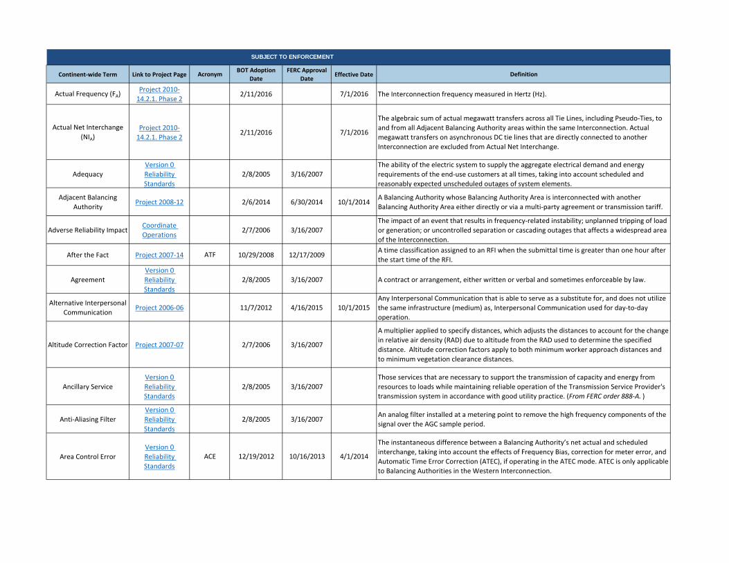
Continent-wide Term Link to Project Page Acronym BOT Adoption Date
FERC Approval Date
Effective Date Definition
Actual Frequency (FA) Project 2010-14.2.1. Phase 2
2/11/2016 7/1/2016 The Interconnection frequency measured in Hertz (Hz).
Actual Net Interchange (NIA)
Project 2010-14.2.1. Phase 2
2/11/2016 7/1/2016
The algebraic sum of actual megawatt transfers across all Tie Lines, including Pseudo-Ties, to and from all Adjacent Balancing Authority areas within the same Interconnection. Actual megawatt transfers on asynchronous DC tie lines that are directly connected to another Interconnection are excluded from Actual Net Interchange.
AdequacyVersion 0 Reliability Standards
2/8/2005 3/16/2007The ability of the electric system to supply the aggregate electrical demand and energy requirements of the end-use customers at all times, taking into account scheduled and reasonably expected unscheduled outages of system elements.
Adjacent Balancing Authority
Project 2008-12 2/6/2014 6/30/2014 10/1/2014A Balancing Authority whose Balancing Authority Area is interconnected with another Balancing Authority Area either directly or via a multi-party agreement or transmission tariff.
Adverse Reliability ImpactCoordinate Operations
2/7/2006 3/16/2007The impact of an event that results in frequency-related instability; unplanned tripping of load or generation; or uncontrolled separation or cascading outages that affects a widespread area of the Interconnection.
After the Fact Project 2007-14 ATF 10/29/2008 12/17/2009 A time classification assigned to an RFI when the submittal time is greater than one hour after the start time of the RFI.
AgreementVersion 0 Reliability Standards
2/8/2005 3/16/2007 A contract or arrangement, either written or verbal and sometimes enforceable by law.
Alternative Interpersonal Communication
Project 2006-06 11/7/2012 4/16/2015 10/1/2015Any Interpersonal Communication that is able to serve as a substitute for, and does not utilize the same infrastructure (medium) as, Interpersonal Communication used for day-to-day operation.
Altitude Correction Factor Project 2007-07 2/7/2006 3/16/2007
A multiplier applied to specify distances, which adjusts the distances to account for the change in relative air density (RAD) due to altitude from the RAD used to determine the specified distance. Altitude correction factors apply to both minimum worker approach distances and to minimum vegetation clearance distances.
Ancillary ServiceVersion 0 Reliability Standards
2/8/2005 3/16/2007Those services that are necessary to support the transmission of capacity and energy from resources to loads while maintaining reliable operation of the Transmission Service Provider's transmission system in accordance with good utility practice. (From FERC order 888-A. )
Anti-Aliasing FilterVersion 0 Reliability Standards
2/8/2005 3/16/2007 An analog filter installed at a metering point to remove the high frequency components of the signal over the AGC sample period.
Area Control ErrorVersion 0 Reliability Standards
ACE 12/19/2012 10/16/2013 4/1/2014
The instantaneous difference between a Balancing Authority’s net actual and scheduled interchange, taking into account the effects of Frequency Bias, correction for meter error, and Automatic Time Error Correction (ATEC), if operating in the ATEC mode. ATEC is only applicable to Balancing Authorities in the Western Interconnection.
SUBJECT TO ENFORCEMENT
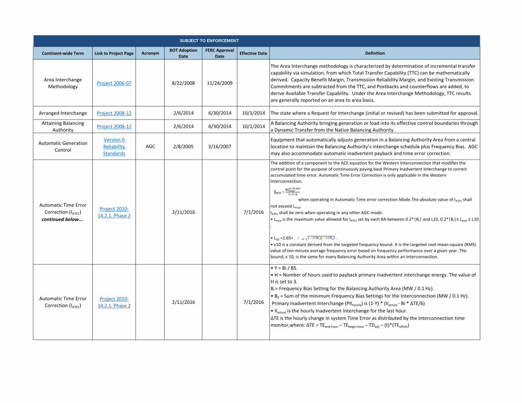
Continent-wide Term Link to Project Page Acronym BOT Adoption Date
FERC Approval Date
Effective Date Definition
SUBJECT TO ENFORCEMENT
Area Interchange Methodology
Project 2006-07 8/22/2008 11/24/2009
The Area Interchange methodology is characterized by determination of incremental transfer capability via simulation, from which Total Transfer Capability (TTC) can be mathematically derived. Capacity Benefit Margin, Transmission Reliability Margin, and Existing Transmission Commitments are subtracted from the TTC, and Postbacks and counterflows are added, to derive Available Transfer Capability. Under the Area Interchange Methodology, TTC results are generally reported on an area to area basis.
Arranged Interchange Project 2008-12 2/6/2014 6/30/2014 10/1/2014 The state where a Request for Interchange (initial or revised) has been submitted for approval.
Attaining Balancing Authority
Project 2008-12 2/6/2014 6/30/2014 10/1/2014 A Balancing Authority bringing generation or load into its effective control boundaries through a Dynamic Transfer from the Native Balancing Authority.
Automatic Generation Control
Version 0 Reliability Standards
AGC 2/8/2005 3/16/2007Equipment that automatically adjusts generation in a Balancing Authority Area from a central location to maintain the Balancing Authority’s interchange schedule plus Frequency Bias. AGC may also accommodate automatic inadvertent payback and time error correction.
Automatic Time Error Correction (IATEC)
continued below...
Project 2010-14.2.1. Phase 2
2/11/2016 7/1/2016
The addition of a component to the ACE equation for the Western Interconnection that modifies the control point for the purpose of continuously paying back Primary Inadvertent Interchange to correct accumulated time error. Automatic Time Error Correction is only applicable in the Western Interconnection.
when operating in Automatic Time error correction Mode.The absolute value of IATEC shall not exceed Lmax. IATEC shall be zero when operating in any other AGC mode. • Lmax is the maximum value allowed for IATEC set by each BA between 0.2*|Bi| and L10, 0.2*|Bi|≤ Lmax ≤ L10
.
• L10 =1.65∗ • ε10 is a constant derived from the targeted frequency bound. It is the targeted root-mean-square (RMS)
value of ten-minute average frequency error based on frequency performance over a given year. The bound, ε 10, is the same for every Balancing Authority Area within an Interconnection.
Automatic Time Error Correction (IATEC)
Project 2010-14.2.1. Phase 2
2/11/2016 7/1/2016
• Y = Bi / BS.
• H = Number of hours used to payback primary inadvertent interchange energy. The value of
H is set to 3.Bi = Frequency Bias Setting for the Balancing Authority Area (MW / 0.1 Hz).• BS = Sum of the minimum Frequency Bias Settings for the Interconnection (MW / 0.1 Hz). Primary Inadvertent Interchange (PIIhourly) is (1-Y) * (IIactual - Bi * ΔTE/6)
• IIactual is the hourly Inadvertent Interchange for the last hour.ΔTE is the hourly change in system Time Error as distributed by the Interconnection time
monitor,where: ΔTE = TEend hour – TEbegin hour – TDadj – (t)*(TEoffset)

Continent-wide Term Link to Project Page Acronym BOT Adoption Date
FERC Approval Date
Effective Date Definition
SUBJECT TO ENFORCEMENT
Automatic Time Error Correction (IATEC)
Project 2010-14.2.1. Phase 2
2/11/2016 7/1/2016
• TDadj is the Reliability Coordinator adjustment for differences with Interconnection time monitor control center clocks. • t is the number of minutes of manual Time Error Correction that occurred during the hour.
• TEoffset is 0.000 or +0.020 or -0.020. • PIIaccum is the Balancing Authority Area’s accumulated PIIhourly in MWh. An On-Peak and Off-Peak accumulation accounting is required, where:
Available Flowgate Capability
Project 2006-07 AFC 8/22/2008 11/24/2009
A measure of the flow capability remaining on a Flowgate for further commercial activity over and above already committed uses. It is defined as TFC less Existing Transmission Commitments (ETC), less a Capacity Benefit Margin, less a Transmission Reliability Margin, plus Postbacks, and plus counterflows.
Available Transfer Capability
Project 2006-07 ATC 8/22/2008 11/24/2009
A measure of the transfer capability remaining in the physical transmission network for further commercial activity over and above already committed uses. It is defined as Total Transfer Capability less Existing Transmission Commitments (including retail customer service), less a Capacity Benefit Margin, less a Transmission Reliability Margin, plus Postbacks, plus counterflows.
Available Transfer Capability
Implementation Document
Project 2006-07 ATCID 8/22/2008 11/24/2009A document that describes the implementation of a methodology for calculating ATC or AFC, and provides information related to a Transmission Service Provider’s calculation of ATC or AFC.
Balancing AuthorityVersion 0 Reliability Standards
BA 2/8/2005 3/16/2007The responsible entity that integrates resource plans ahead of time, maintains load-interchange-generation balance within a Balancing Authority Area, and supports Interconnection frequency in real time.
Balancing Authority AreaVersion 0 Reliability Standards
2/8/2005 3/16/2007The collection of generation, transmission, and loads within the metered boundaries of the Balancing Authority. The Balancing Authority maintains load-resource balance within this area.
Base Load Version 0 Reliability
2/8/2005 3/16/2007 The minimum amount of electric power delivered or required over a given period at a constant rate.
BES Cyber Asset Project 2014-02 BCA 2/12/2015 1/21/2016 7/1/2016
A Cyber Asset that if rendered unavailable, degraded, or misused would, within 15 minutes of its required operation, misoperation, or non-operation, adversely impact one or more Facilities, systems, or equipment, which, if destroyed, degraded, or otherwise rendered unavailable when needed, would affect the reliable operation of the Bulk Electric System. Redundancy of affected Facilities, systems, and equipment shall not be considered when determining adverse impact. Each BES Cyber Asset is included in one or more BES Cyber Systems.
BES Cyber System Project 2008-06 11/26/2012 11/22/2013 7/1/2016 One or more BES Cyber Assets logically grouped by a responsible entity to perform one or more reliability tasks for a functional entity.

Continent-wide Term Link to Project Page Acronym BOT Adoption Date
FERC Approval Date
Effective Date Definition
SUBJECT TO ENFORCEMENT
BES Cyber System Information
Project 2008-06 11/26/2012 11/22/2013 7/1/2016
Information about the BES Cyber System that could be used to gain unauthorized access or pose a security threat to the BES Cyber System. BES Cyber System Information does not include individual pieces of information that by themselves do not pose a threat or could not be used to allow unauthorized access to BES Cyber Systems, such as, but not limited to, device names, individual IP addresses without context, ESP names, or policy statements. Examples of BES Cyber System Information may include, but are not limited to, security procedures or security information about BES Cyber Systems, Physical Access Control Systems, and Electronic Access Control or Monitoring Systems that is not publicly available and could be used to allow unauthorized access or unauthorized distribution; collections of network addresses; and network topology of the BES Cyber System.
Blackstart Resource Project 2015-04 11/5/2015 1/21/2016 7/1/2016
A generating unit(s) and its associated set of equipment which has the ability to be started without support from the System or is designed to remain energized without connection to the remainder of the System, with the ability to energize a bus, meeting the Transmission Operator’s restoration plan needs for Real and Reactive Power capability, frequency and voltage control, and that has been included in the Transmission Operator’s restoration plan.
Block Dispatch Project 2006-07 8/22/2008 11/24/2009
A set of dispatch rules such that given a specific amount of load to serve, an approximate generation dispatch can be determined. To accomplish this, the capacity of a given generator is segmented into loadable “blocks,” each of which is grouped and ordered relative to other blocks (based on characteristics including, but not limited to, efficiency, run of river or fuel supply considerations, and/or “must-run” status).
Bulk Electric System (Continued below)
Project 2010-17 BES 11/21/2013 3/20/2014
7/1/2014 (Please see the Imple-mentation
Plan for Phase 2
Compliance obligations.)
Unless modified by the lists shown below, all Transmission Elements operated at 100 kV or higher and Real Power and Reactive Power resources connected at 100 kV or higher. This does not include facilities used in the local distribution of electric energy.Inclusions:• I1 - Transformers with the primary terminal and at least one secondary terminal operated at
100 kV or higher unless excluded by application of Exclusion E1 or E3.• I2 – Generating resource(s) including the generator terminals through the high-side of the
step-up transformer(s) connected at a voltage of 100 kV or above with:a) Gross individual nameplate rating greater than 20 MVA. Or, b) Gross plant/facility aggregate nameplate rating greater than 75 MVA. • I3 - Blackstart Resources identified in the Transmission Operator’s restoration plan.
• I4 - Dispersed power producing resources that aggregate to a total capacity greater than 75
MVA (gross nameplate rating), and that are connected through a system designed primarily for delivering such capacity to a common point of connection at a voltage of 100 kV or above. Thus, the facilities designated as BES are:

Continent-wide Term Link to Project Page Acronym BOT Adoption Date
FERC Approval Date
Effective Date Definition
SUBJECT TO ENFORCEMENT
Bulk Electric System (continued below)
Project 2010-17 BES 11/21/2013 3/20/2014
7/1/2014 (Please see the Imple-mentation
Plan for Phase 2
Compliance obligations.)
a) The individual resources, and b) The system designed primarily for delivering capacity from the point where those resources aggregate to greater than 75 MVA to a common point of connection at a voltage of 100 kV or above. • I5 –Static or dynamic devices (excluding generators) dedicated to supplying or absorbing
Reactive Power that are connected at 100 kV or higher, or through a dedicated transformer with a high-side voltage of 100 kV or higher, or through a transformer that is designated in Inclusion I1 unless excluded by application of Exclusion E4. Exclusions: • E1 - Radial systems: A group of contiguous transmission Elements that emanates from a
single point of connection of 100 kV or higher and:a) Only serves Load. Or,b) Only includes generation resources, not identified in Inclusions I2, I3, or I4, with an aggregate capacity less than or equal to 75 MVA (gross nameplate rating). Or,c) Where the radial system serves Load and includes generation resources, not identified in Inclusions I2, I3 or I4, with an aggregate capacity of non-retail generation less than or equal to 75 MVA (gross nameplate rating).
Bulk Electric System (continued)
Project 2010-17 BES 11/21/2013 3/20/2014
7/1/2014 (Please see the Imple-mentation
Plan for Phase 2
Compliance obligations.)
y p g y , p p one-line diagrams for example, does not affect this exclusion. Note 2 – The presence of a contiguous loop, operated at a voltage level of 50 kV or less, between configurations being considered as radial systems, does not affect this exclusion.• E2 - A generating unit or multiple generating units on the customer’s side of the retail meter that serve all or part of the retail Load with electric energy if: (i) the net capacity provided to the BES does not exceed 75 MVA, and (ii) standby, back-up, and maintenance power services are provided to the generating unit or multiple generating units or to the retail Load by a Balancing Authority, or provided pursuant to a binding obligation with a Generator Owner or Generator Operator, or under terms approved by the applicable regulatory authority.• E3 - Local networks (LN): A group of contiguous transmission Elements operated at less than 300 kV that distribute power to Load rather than transfer bulk power across the interconnected system. LN’s emanate from multiple points of connection at 100 kV or higher to improve the level of service to retail customers and not to accommodate bulk power transfer across the interconnected system. The LN is characterized by all of the following:a) Limits on connected generation: The LN and its underlying Elements do not include generation resources identified in Inclusions I2, I3, or I4 and do not have an aggregate capacity of non-retail

Continent-wide Term Link to Project Page Acronym BOT Adoption Date
FERC Approval Date
Effective Date Definition
SUBJECT TO ENFORCEMENT
Bulk Electric System (continued)
Project 2010-17 BES 11/21/2013 3/20/2014
7/1/2014 (Please see the Imple-mentation
Plan for Phase 2
Compliance obligations.)
a) Limits on connected generation: The LN and its underlying Elements do not include generation resources identified in Inclusions I2, I3, or I4 and do not have an aggregate capacity of non-retail generation greater than 75 MVA (gross nameplate rating);b) Real Power flows only into the LN and the LN does not transfer energy originating outside the LN for delivery through the LN; andc) Not part of a Flowgate or transfer path: The LN does not contain any part of a permanent Flowgate in the Eastern Interconnection, a major transfer path within the Western Interconnection, or a comparable monitored Facility in the ERCOT or Quebec Interconnections, and is not a monitored Facility included in an Interconnection Reliability Operating Limit (IROL).• E4 – Reactive Power devices installed for the sole benefit of a retail customer(s).
Note - Elements may be included or excluded on a case-by-case basis through the Rules of Procedure exception process.
Bulk-Power System Project 2015-04 11/5/2015 1/21/2016 7/1/2016
Bulk-Power System: (A) facilities and control systems necessary for operating an interconnected electric energy transmission network (or any portion thereof); and (B) electric energy from generation facilities needed to maintain transmission system reliability. The term does not include facilities used in the local distribution of electric energy. (Note that the terms “Bulk-Power System” or “Bulk Power System” shall have the same meaning.)
BurdenVersion 0 Reliability Standards
2/8/2005 3/16/2007
Operation of the Bulk Electric System that violates or is expected to violate a System Operating Limit or Interconnection Reliability Operating Limit in the Interconnection, or that violates any other NERC, Regional Reliability Organization, or local operating reliability standards or criteria.
Bus-tie Breaker Project 2006-02 8/4/2011 10/17/2013 1/1/2015 A circuit breaker that is positioned to connect two individual substation bus configurations.
Capacity Benefit MarginVersion 0 Reliability Standards
CBM 2/8/2005 3/16/2007
The amount of firm transmission transfer capability preserved by the transmission provider for Load-Serving Entities (LSEs), whose loads are located on that Transmission Service Provider’s system, to enable access by the LSEs to generation from interconnected systems to meet generation reliability requirements. Preservation of CBM for an LSE allows that entity to reduce its installed generating capacity below that which may otherwise have been necessary without interconnections to meet its generation reliability requirements. The transmission transfer capability preserved as CBM is intended to be used by the LSE only in times of emergency generation deficiencies.
Capacity Benefit Margin Implementation
DocumentProject 2006-07 CBMID 11/13/2008 11/24/2009 A document that describes the implementation of a Capacity Benefit Margin methodology.
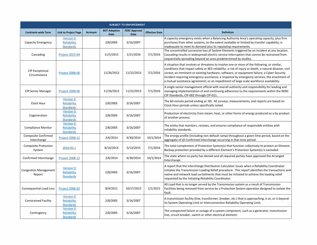
Continent-wide Term Link to Project Page Acronym BOT Adoption Date
FERC Approval Date
Effective Date Definition
SUBJECT TO ENFORCEMENT
Capacity EmergencyVersion 0 Reliability Standards
2/8/2005 3/16/2007A capacity emergency exists when a Balancing Authority Area’s operating capacity, plus firm purchases from other systems, to the extent available or limited by transfer capability, is inadequate to meet its demand plus its regulating requirements.
Cascading Project 2015-04 11/5/2015 1/21/2016 7/1/2016The uncontrolled successive loss of System Elements triggered by an incident at any location. Cascading results in widespread electric service interruption that cannot be restrained from sequentially spreading beyond an area predetermined by studies.
CIP Exceptional Circumstance
Project 2008-06 11/26/2012 11/22/2013 7/1/2016
A situation that involves or threatens to involve one or more of the following, or similar, conditions that impact safety or BES reliability: a risk of injury or death; a natural disaster; civil unrest; an imminent or existing hardware, software, or equipment failure; a Cyber Security Incident requiring emergency assistance; a response by emergency services; the enactment of a mutual assistance agreement; or an impediment of large scale workforce availability.
CIP Senior Manager Project 2008-06 11/26/2012 11/22/2013 7/1/2016A single senior management official with overall authority and responsibility for leading and managing implementation of and continuing adherence to the requirements within the NERC CIP Standards, CIP-002 through CIP-011.
Clock HourVersion 0 Reliability Standards
2/8/2005 3/16/2007 The 60-minute period ending at :00. All surveys, measurements, and reports are based on Clock Hour periods unless specifically noted.
CogenerationVersion 0 Reliability Standards
2/8/2005 3/16/2007 Production of electricity from steam, heat, or other forms of energy produced as a by-product of another process.
Compliance MonitorVersion 0 Reliability Standards
2/8/2005 3/16/2007 The entity that monitors, reviews, and ensures compliance of responsible entities with reliability standards.
Composite Confirmed Interchange
Project 2008-12 2/6/2014 6/30/2014 10/1/2014 The energy profile (including non-default ramp) throughout a given time period, based on the aggregate of all Confirmed Interchange occurring in that time period.
Composite Protection System
2010-05.1 8/14/2014 5/13/2015 7/1/2016 The total complement of Protection System(s) that function collectively to protect an Element. Backup protection provided by a different Element’s Protection System(s) is excluded.
Confirmed Interchange Project 2008-12 2/6/2014 6/30/2014 10/1/2014 The state where no party has denied and all required parties have approved the Arranged Interchange.
Congestion Management Report
Version 0 Reliability Standards
2/8/2005 3/16/2007
A report that the Interchange Distribution Calculator issues when a Reliability Coordinator initiates the Transmission Loading Relief procedure. This report identifies the transactions and native and network load curtailments that must be initiated to achieve the loading relief requested by the initiating Reliability Coordinator.
Consequential Load Loss Project 2006-02 8/4/2011 10/17/2013 1/1/2015All Load that is no longer served by the Transmission system as a result of Transmission Facilities being removed from service by a Protection System operation designed to isolate the fault.
Constrained FacilityVersion 0 Reliability Standards
2/8/2005 3/16/2007 A transmission facility (line, transformer, breaker, etc.) that is approaching, is at, or is beyond its System Operating Limit or Interconnection Reliability Operating Limit.
ContingencyVersion 0 Reliability Standards
2/8/2005 3/16/2007 The unexpected failure or outage of a system component, such as a generator, transmission line, circuit breaker, switch or other electrical element.

Continent-wide Term Link to Project Page Acronym BOT Adoption Date
FERC Approval Date
Effective Date Definition
SUBJECT TO ENFORCEMENT
Contingency ReserveVersion 0 Reliability Standards
2/8/2005 3/16/2007The provision of capacity deployed by the Balancing Authority to meet the Disturbance Control Standard (DCS) and other NERC and Regional Reliability Organization contingency requirements.
Contact PathVersion 0 Reliability Standards
2/8/2005 3/16/2007An agreed upon electrical path for the continuous flow of electrical power between the parties of an Interchange Transaction.
Control Center Project 2008-06 11/26/2012 11/22/2013 7/1/2016
One or more facilities hosting operating personnel that monitor and control the Bulk Electric System (BES) in real-time to perform the reliability tasks, including their associated data centers, of: 1) a Reliability Coordinator, 2) a Balancing Authority, 3) a Transmission Operator for transmission Facilities at two or more locations, or 4) a Generator Operator for generation Facilities at two or more locations.
Control Performance Standard
Version 0 Reliability Standards
CPS 2/8/2005 3/16/2007The reliability standard that sets the limits of a Balancing Authority’s Area Control Error over a specified time period.
Corrective Action Plan
Phase III-IV Planning
Standards - Archive
2/7/2006 3/16/2007 A list of actions and an associated timetable for implementation to remedy a specific problem.
Cranking Path
Phase III-IV Planning
Standards - Archive
5/2/2006 3/16/2007 A portion of the electric system that can be isolated and then energized to deliver electric power from a generation source to enable the startup of one or more other generating units.
CurtailmentVersion 0 Reliability Standards
2/8/2005 3/16/2007 A reduction in the scheduled capacity or energy delivery of an Interchange Transaction.
Curtailment ThresholdVersion 0 Reliability Standards
2/8/2005 3/16/2007 The minimum Transfer Distribution Factor which, if exceeded, will subject an Interchange Transaction to curtailment to relieve a transmission facility constraint.
Cyber Assets Project 2008-06 11/26/2012 11/22/2013 7/1/2016 Programmable electronic devices, including the hardware, software, and data in those devices.
Cyber Security Incident Project 2008-06 11/26/2012 11/22/2013 7/1/2016
A malicious act or suspicious event that:• Compromises, or was an attempt to compromise, the Electronic Security Perimeter or
Physical Security Perimeter or, • Disrupts, or was an attempt to disrupt, the operation of a BES Cyber System.
Delayed Fault Clearing
Determine Facility Ratings, Operating
Limits, and Transfer
Capabilities
11/1/2006 12/27/2007 Fault clearing consistent with correct operation of a breaker failure protection system and its associated breakers, or of a backup protection system with an intentional time delay.
DemandVersion 0 Reliability Standards
2/8/2005 3/16/2007
1. The rate at which electric energy is delivered to or by a system or part of a system, generally expressed in kilowatts or megawatts, at a given instant or averaged over any designated interval of time. 2. The rate at which energy is being used by the customer.

Continent-wide Term Link to Project Page Acronym BOT Adoption Date
FERC Approval Date
Effective Date Definition
SUBJECT TO ENFORCEMENT
Demand-Side Management Project 2010-04 DSM 5/6/2014 2/19/2015 7/1/2016 All activities or programs undertaken by any applicable entity to achieve a reduction in
Demand.
Dial-up Connectivity Project 2008-06 11/26/2012 11/22/2013 7/1/2016 A data communication link that is established when the communication equipment dials a phone number and negotiates a connection with the equipment on the other end of the link.
Direct Control Load Management
Project 2008-06 DCLM 2/8/2005 3/16/2007Demand-Side Management that is under the direct control of the system operator. DCLM may control the electric supply to individual appliances or equipment on customer premises. DCLM as defined here does not include Interruptible Demand.
Dispatch Order Project 2006-07 8/22/2008 11/24/2009A set of dispatch rules such that given a specific amount of load to serve, an approximate generation dispatch can be determined. To accomplish this, each generator is ranked by priority.
Dispersed Load by Substations
Version 0 Reliability Standards
2/8/2005 3/16/2007Substation load information configured to represent a system for power flow or system dynamics modeling purposes, or both.
Distribution FactorVersion 0 Reliability Standards
DF 2/8/2005 3/16/2007The portion of an Interchange Transaction, typically expressed in per unit that flows across a transmission facility (Flowgate).
Distribution Provider Project 2015-04 DP 11/5/2015 1/21/2016 7/1/2016
Provides and operates the “wires” between the transmission system and the end-use customer. For those end-use customers who are served at transmission voltages, the Transmission Owner also serves as the Distribution Provider. Thus, the Distribution Provider is not defined by a specific voltage, but rather as performing the distribution function at any voltage.
DisturbanceVersion 0 Reliability Standards
2/8/2005 3/16/2007
1. An unplanned event that produces an abnormal system condition. 2. Any perturbation to the electric system. 3. The unexpected change in ACE that is caused by the sudden failure of generation or interruption of load.
Disturbance Control Standard
Version 0 Reliability Standards
DCS 2/8/2005 3/16/2007 The reliability standard that sets the time limit following a Disturbance within which a Balancing Authority must return its Area Control Error to within a specified range.
Disturbance Monitoring Equipment
Phase III-IV Planning
StandardsDME 8/2/2006 3/16/2007
Devices capable of monitoring and recording system data pertaining to a Disturbance. Such devices include the following categories of recorders* :• Sequence of event recorders which record equipment response to the event
• Fault recorders, which record actual waveform data replicating the system primary voltages
and currents. This may include protective relays.• Dynamic Disturbance Recorders (DDRs), which record incidents that portray power system
behavior during dynamic events such as low-frequency (0.1 Hz – 3 Hz) oscillations and abnormal frequency or voltage excursions*Phasor Measurement Units and any other equipment that meets the functional requirements of DMEs may qualify as DMEs.
Dynamic Interchange Schedule or
Dynamic ScheduleProject 2008-12 2/6/2014 6/30/2014 10/1/2014
A time-varying energy transfer that is updated in Real-time and included in the Scheduled Net Interchange (NIS) term in the same manner as an Interchange Schedule in the affected Balancing Authorities’ control ACE equations (or alternate control processes).

Continent-wide Term Link to Project Page Acronym BOT Adoption Date
FERC Approval Date
Effective Date Definition
SUBJECT TO ENFORCEMENT
Dynamic TransferVersion 0 Reliability Standards
2/8/2005 3/16/2007
The provision of the real-time monitoring, telemetering, computer software, hardware, communications, engineering, energy accounting (including inadvertent interchange), and administration required to electronically move all or a portion of the real energy services associated with a generator or load out of one Balancing Authority Area into another.
Economic DispatchVersion 0 Reliability Standards
2/8/2005 3/16/2007The allocation of demand to individual generating units on line to effect the most economical production of electricity.
Electronic Access Control or Monitoring Systems
Project 2008-06 Order 706
EACMS 11/26/2012 11/22/2013 7/1/2016 Cyber Assets that perform electronic access control or electronic access monitoring of the Electronic Security Perimeter(s) or BES Cyber Systems. This includes Intermediate Systems.
Electronic Access PointProject 2008-06
Order 706EAP 11/26/2012 11/22/2013 7/1/2016
A Cyber Asset interface on an Electronic Security Perimeter that allows routable communication between Cyber Assets outside an Electronic Security Perimeter and Cyber Assets inside an Electronic Security Perimeter.
Electrical EnergyVersion 0 Reliability Standards
2/8/2005 3/16/2007 The generation or use of electric power by a device over a period of time, expressed in kilowatthours (kWh), megawatthours (MWh), or gigawatthours (GWh).
Electronic Security Perimeter
Project 2008-06 Order 706
ESP 11/26/2012 11/22/2013 7/1/2016 The logical border surrounding a network to which BES Cyber Systems are connected using a routable protocol.
Element Project 2015-04 11/5/2015 1/21/2016 7/1/2016Any electrical device with terminals that may be connected to other electrical devices such as a generator, transformer, circuit breaker, bus section, or transmission line. An Element may be comprised of one or more components.
Emergency or BES Emergency
Version 0 Reliability Standards
2/8/2005 3/16/2007Any abnormal system condition that requires automatic or immediate manual action to prevent or limit the failure of transmission facilities or generation supply that could adversely affect the reliability of the Bulk Electric System.
Emergency RatingVersion 0 Reliability Standards
2/8/2005 3/16/2007
The rating as defined by the equipment owner that specifies the level of electrical loading or output, usually expressed in megawatts (MW) or Mvar or other appropriate units, that a system, facility, or element can support, produce, or withstand for a finite period. The rating assumes acceptable loss of equipment life or other physical or safety limitations for the equipment involved.
Emergency Request for Interchange
Project 2007-14 Coordinate Interchange
Emergency RFI
10/29/2008 12/17/2009 Request for Interchange to be initiated for Emergency or Energy Emergency conditions.
Energy Emergency Version 0 11/13/2014 11/19/2015 4/1/2017A condition when a Load-Serving Entity or Balancing Authority has exhausted all other resource options and can no longer meet its expected Load obligations.
Equipment Rating
Determine Facility Ratings, Operating
Limits, and Transfer
Capabilities
2/7/2006 3/16/2007The maximum and minimum voltage, current, frequency, real and reactive power flows on individual equipment under steady state, short-circuit and transient conditions, as permitted or assigned by the equipment owner.
External Routable Connectivity
Project 2008-06 Order 706
11/26/2012 11/22/2013 7/1/2016 The ability to access a BES Cyber System from a Cyber Asset that is outside of its associated Electronic Security Perimeter via a bi-directional routable protocol connection.
Existing Transmission Commitments
Project 2006-07 ETC 8/22/2008 11/24/2009 Committed uses of a Transmission Service Provider’s Transmission system considered when determining ATC or AFC.

Continent-wide Term Link to Project Page Acronym BOT Adoption Date
FERC Approval Date
Effective Date Definition
SUBJECT TO ENFORCEMENT
Facility
Determine Facility Ratings, Operating
Limits, and Transfer
Capabilities
2/7/2006 3/16/2007A set of electrical equipment that operates as a single Bulk Electric System Element (e.g., a line, a generator, a shunt compensator, transformer, etc.)
Facility RatingVersion 0 Reliability Standards
2/8/2005 3/16/2007The maximum or minimum voltage, current, frequency, or real or reactive power flow through a facility that does not violate the applicable equipment rating of any equipment comprising the facility.
FaultVersion 0 Reliability Standards
2/8/2005 3/16/2007An event occurring on an electric system such as a short circuit, a broken wire, or an intermittent connection.
Fire Risk Project 2007-07 2/7/2006 3/16/2007 The likelihood that a fire will ignite or spread in a particular geographic area.
Firm DemandVersion 0 Reliability Standards
2/8/2005 3/16/2007That portion of the Demand that a power supplier is obligated to provide except when system reliability is threatened or during emergency conditions.
Firm Transmission ServiceVersion 0 Reliability Standards
2/8/2005 3/16/2007 The highest quality (priority) service offered to customers under a filed rate schedule that anticipates no planned interruption.
Flashover Project 2007-07 2/7/2006 3/16/2007An electrical discharge through air around or over the surface of insulation, between objects of different potential, caused by placing a voltage across the air space that results in the ionization of the air space.
Flowgate Project 2006-07 8/22/2008 11/24/2009
1.) A portion of the Transmission system through which the Interchange Distribution Calculator calculates the power flow from Interchange Transactions.2.) A mathematical construct, comprised of one or more monitored transmission Facilities and optionally one or more contingency Facilities, used to analyze the impact of power flows upon the Bulk Electric System.
Flowgate MethodologyVersion 0 Reliability Standards
8/22/2008 11/24/2009
The Flowgate methodology is characterized by identification of key Facilities as Flowgates. Total Flowgate Capabilities are determined based on Facility Ratings and voltage and stability limits. The impacts of Existing Transmission Commitments (ETCs) are determined by simulation. The impacts of ETC, Capacity Benefit Margin (CBM) and Transmission Reliability Margin (TRM) are subtracted from the Total Flowgate Capability, and Postbacks and counterflows are added, to determine the Available Flowgate Capability (AFC) value for that Flowgate. AFCs can be used to determine Available Transfer Capability (ATC).
Forced OutageVersion 0 Reliability Standards
2/8/2005 3/16/2007
1. The removal from service availability of a generating unit, transmission line, or other facility for emergency reasons. 2. The condition in which the equipment is unavailable due to unanticipated failure.
Frequency BiasVersion 0 Reliability Standards
2/8/2005 3/16/2007A value, usually expressed in megawatts per 0.1 Hertz (MW/0.1 Hz), associated with a Balancing Authority Area that approximates the Balancing Authority Area’s response to Interconnection frequency error.

Continent-wide Term Link to Project Page Acronym BOT Adoption Date
FERC Approval Date
Effective Date Definition
SUBJECT TO ENFORCEMENT
Frequency Bias Setting Project 2007-12 2/7/2013 1/16/2014 4/1/2015
A number, either fixed or variable, usually expressed in MW/0.1 Hz, included in a Balancing Authority’s Area Control Error equation to account for the Balancing Authority’s inverse Frequency Response contribution to the Interconnection, and discourage response withdrawal through secondary control systems.
Frequency Deviation Version 0 2/8/2005 3/16/2007 A change in Interconnection frequency.
Frequency ErrorVersion 0 Reliability Standards
2/8/2005 3/16/2007 The difference between the actual and scheduled frequency. (FA – FS)
Frequency RegulationVersion 0 Reliability Standards
2/8/2005 3/16/2007The ability of a Balancing Authority to help the Interconnection maintain Scheduled Frequency. This assistance can include both turbine governor response and Automatic Generation Control.
Frequency ResponseVersion 0 Reliability Standards
2/8/2005 3/16/2007
(Equipment) The ability of a system or elements of the system to react or respond to a change in system frequency.(System) The sum of the change in demand, plus the change in generation, divided by the change in frequency, expressed in megawatts per 0.1 Hertz (MW/0.1 Hz).
Frequency Response Measure
Project 2007-12 FRM 2/7/2013 1/16/2014 4/1/2015The median of all the Frequency Response observations reported annually by Balancing Authorities or Frequency Response Sharing Groups for frequency events specified by the ERO. This will be calculated as MW/0.1Hz.
Frequency Response Obligation
Project 2007-12 FRO 2/7/2013 1/16/2014 4/1/2015 The Balancing Authority’s share of the required Frequency Response needed for the reliable operation of an Interconnection. This will be calculated as MW/0.1Hz.
Frequency Response Sharing Group
Project 2007-12 FRSG 2/7/2013 1/16/2014 4/1/2015A group whose members consist of two or more Balancing Authorities that collectively maintain, allocate, and supply operating resources required to jointly meet the sum of the Frequency Response Obligations of its members.
Generator OperatorVersion 0 Reliability Standards
GOP 11/5/2015 1/21/2016 7/1/2016 The entity that operates generating Facility(ies) and performs the functions of supplying energy and Interconnected Operations Services.
Generator Owner Version 0 GO 11/5/2015 1/21/2016 7/1/2016 Entity that owns and maintains generating Facility(ies).
Generator Shift FactorVersion 0 Reliability Standards
GSF 2/8/2005 3/16/2007A factor to be applied to a generator’s expected change in output to determine the amount of flow contribution that change in output will impose on an identified transmission facility or Flowgate.
Generator-to-Load Distribution Factor
Version 0 Reliability Standards
GLDF 2/8/2005 3/16/2007 The algebraic sum of a Generator Shift Factor and a Load Shift Factor to determine the total impact of an Interchange Transaction on an identified transmission facility or Flowgate.
Generation Capability Import Requirement
Project 2006-07 ATC/TTC/AFC and
CBM/TRM Revisions
GCIR 11/13/2008 11/24/2009The amount of generation capability from external sources identified by a Load-Serving Entity (LSE) or Resource Planner (RP) to meet its generation reliability or resource adequacy requirements as an alternative to internal resources.
Geomagnetic Disturbance Vulnerability Assessment
or GMD Vulnerability Assessment
Project 2013-03 Geomagnetic Disturbance Mitigation
GMD 12/17/2014 9/22/2016 7/1/2017 Documented evaluation of potential susceptibility to voltage collapse, Cascading, or localized damage of equipment due to geomagnetic disturbances.

Continent-wide Term Link to Project Page Acronym BOT Adoption Date
FERC Approval Date
Effective Date Definition
SUBJECT TO ENFORCEMENT
Host Balancing AuthorityVersion 0 Reliability Standards
2/8/2005 3/16/2007
1. A Balancing Authority that confirms and implements Interchange Transactions for a Purchasing Selling Entity that operates generation or serves customers directly within the Balancing Authority’s metered boundaries. 2. The Balancing Authority within whose metered boundaries a jointly owned unit is physically located.
Hourly Value Version 0 Reliability
2/8/2005 3/16/2007 Data measured on a Clock Hour basis.
Implemented Interchange Coordinate Interchange
5/2/2006 3/16/2007 The state where the Balancing Authority enters the Confirmed Interchange into its Area Control Error equation.
Inadvertent InterchangeVersion 0 Reliability Standards
2/8/2005 3/16/2007The difference between the Balancing Authority’s Net Actual Interchange and Net Scheduled Interchange. (IA – IS)
Independent Power Producer
Version 0 Reliability Standards
IPP 2/8/2005 3/16/2007
Any entity that owns or operates an electricity generating facility that is not included in an electric utility’s rate base. This term includes, but is not limited to, cogenerators and small power producers and all other nonutility electricity producers, such as exempt wholesale generators, who sell electricity.
Institute of Electrical and Electronics Engineers, Inc.
Project 2007-07 IEEE 2/7/2006 3/16/2007
Interactive Remote Access
Project 2008-06 11/26/2012 11/22/2013 7/1/2016
User-initiated access by a person employing a remote access client or other remote access technology using a routable protocol. Remote access originates from a Cyber Asset that is not an Intermediate System and not located within any of the Responsible Entity’s Electronic Security Perimeter(s) or at a defined Electronic Access Point (EAP). Remote access may be initiated from: 1) Cyber Assets used or owned by the Responsible Entity, 2) Cyber Assets used or owned by employees, and 3) Cyber Assets used or owned by vendors, contractors, or consultants. Interactive remote access does not include system-to-system process communications.
Interchange Coordinate Interchange
5/2/2006 3/16/2007 Energy transfers that cross Balancing Authority boundaries.
Interchange Authority Project 2015-04 IA 11/5/2015 1/21/2016 7/1/2016The responsible entity that authorizes the implementation of valid and balanced Interchange Schedules between Balancing Authority Areas, and ensures communication of Interchange information for reliability assessment purposes.
Interchange Distribution Calculator
Version 0 Reliability Standards
2/8/2005 3/16/2007
The mechanism used by Reliability Coordinators in the Eastern Interconnection to calculate the distribution of Interchange Transactions over specific Flowgates. It includes a database of all Interchange Transactions and a matrix of the Distribution Factors for the Eastern Interconnection.
Interchange Meter Error (IME)
Project 2010-14.2.1. Phase 2
2/11/2016 7/1/2016 A term used in the Reporting ACE calculation to compensate for data or equipment errors affecting any other components of the Reporting ACE calculation.
Interchange ScheduleVersion 0 Reliability Standards
2/8/2005 3/16/2007An agreed-upon Interchange Transaction size (megawatts), start and end time, beginning and ending ramp times and rate, and type required for delivery and receipt of power and energy between the Source and Sink Balancing Authorities involved in the transaction.
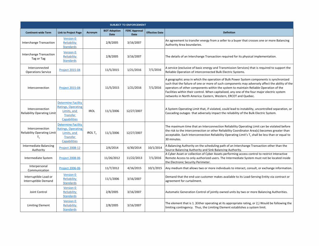
Continent-wide Term Link to Project Page Acronym BOT Adoption Date
FERC Approval Date
Effective Date Definition
SUBJECT TO ENFORCEMENT
Interchange TransactionVersion 0 Reliability Standards
2/8/2005 3/16/2007 An agreement to transfer energy from a seller to a buyer that crosses one or more Balancing Authority Area boundaries.
Interchange Transaction Tag or Tag
Version 0 Reliability Standards
2/8/2005 3/16/2007 The details of an Interchange Transaction required for its physical implementation.
Interconnected Operations Service
Project 2015-04 11/5/2015 1/21/2016 7/1/2016 A service (exclusive of basic energy and Transmission Services) that is required to support the Reliable Operation of interconnected Bulk Electric Systems.
Interconnection Project 2015-04 11/5/2015 1/21/2016 7/1/2016
A geographic area in which the operation of Bulk Power System components is synchronized such that the failure of one or more of such components may adversely affect the ability of the operators of other components within the system to maintain Reliable Operation of the Facilities within their control. When capitalized, any one of the four major electric system networks in North America: Eastern, Western, ERCOT and Quebec.
Interconnection Reliability Operating Limit
Determine Facility Ratings, Operating
Limits, and Transfer
Capabilities
IROL 11/1/2006 12/27/2007A System Operating Limit that, if violated, could lead to instability, uncontrolled separation, or Cascading outages that adversely impact the reliability of the Bulk Electric System.
Interconnection Reliability Operating Limit
Tv
Determine Facility Ratings, Operating
Limits, and Transfer
Capabilities
IROL Tv 11/1/2006 12/27/2007
The maximum time that an Interconnection Reliability Operating Limit can be violated before the risk to the interconnection or other Reliability Coordinator Area(s) becomes greater than acceptable. Each Interconnection Reliability Operating Limit’s Tv shall be less than or equal to 30 minutes.
Intermediate Balancing Authority
Project 2008-12 2/6/2014 6/30/2014 10/1/2014 A Balancing Authority on the scheduling path of an Interchange Transaction other than the Source Balancing Authority and Sink Balancing Authority.
Intermediate System Project 2008-06 11/26/2012 11/22/2013 7/1/2016A Cyber Asset or collection of Cyber Assets performing access control to restrict Interactive Remote Access to only authorized users. The Intermediate System must not be located inside the Electronic Security Perimeter.
Interpersonal Communication
Project 2006-06 11/7/2012 4/16/2015 10/1/2015 Any medium that allows two or more individuals to interact, consult, or exchange information.
Interruptible Load or Interruptible Demand
Version 0 Reliability Standards
11/1/2006 3/16/2007 Demand that the end-use customer makes available to its Load-Serving Entity via contract or agreement for curtailment.
Joint ControlVersion 0 Reliability Standards
2/8/2005 3/16/2007 Automatic Generation Control of jointly owned units by two or more Balancing Authorities.
Limiting ElementVersion 0 Reliability Standards
2/8/2005 3/16/2007 The element that is 1. )Either operating at its appropriate rating, or 2,) Would be following the limiting contingency. Thus, the Limiting Element establishes a system limit.
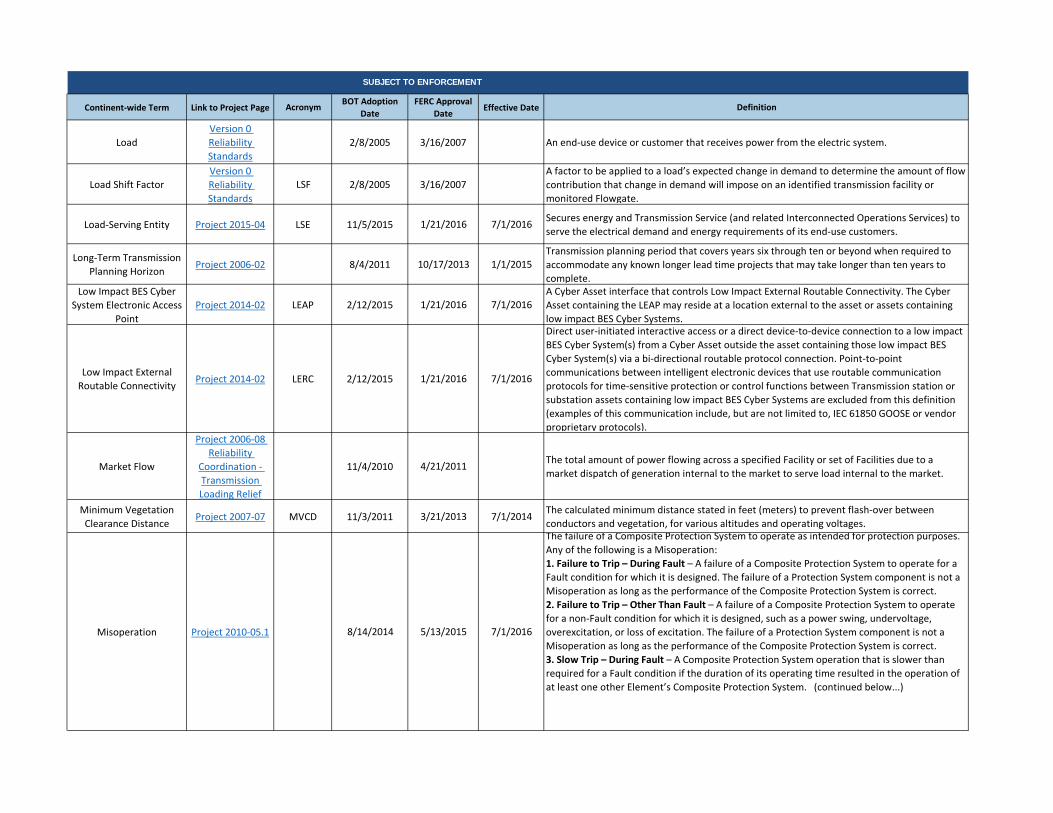
Continent-wide Term Link to Project Page Acronym BOT Adoption Date
FERC Approval Date
Effective Date Definition
SUBJECT TO ENFORCEMENT
LoadVersion 0 Reliability Standards
2/8/2005 3/16/2007 An end-use device or customer that receives power from the electric system.
Load Shift FactorVersion 0 Reliability Standards
LSF 2/8/2005 3/16/2007A factor to be applied to a load’s expected change in demand to determine the amount of flow contribution that change in demand will impose on an identified transmission facility or monitored Flowgate.
Load-Serving Entity Project 2015-04 LSE 11/5/2015 1/21/2016 7/1/2016 Secures energy and Transmission Service (and related Interconnected Operations Services) to serve the electrical demand and energy requirements of its end-use customers.
Long-Term Transmission Planning Horizon
Project 2006-02 8/4/2011 10/17/2013 1/1/2015Transmission planning period that covers years six through ten or beyond when required to accommodate any known longer lead time projects that may take longer than ten years to complete.
Low Impact BES Cyber System Electronic Access
PointProject 2014-02 LEAP 2/12/2015 1/21/2016 7/1/2016
A Cyber Asset interface that controls Low Impact External Routable Connectivity. The Cyber Asset containing the LEAP may reside at a location external to the asset or assets containing low impact BES Cyber Systems.
Low Impact External Routable Connectivity
Project 2014-02 LERC 2/12/2015 1/21/2016 7/1/2016
Direct user-initiated interactive access or a direct device-to-device connection to a low impact BES Cyber System(s) from a Cyber Asset outside the asset containing those low impact BES Cyber System(s) via a bi-directional routable protocol connection. Point-to-point communications between intelligent electronic devices that use routable communication protocols for time-sensitive protection or control functions between Transmission station or substation assets containing low impact BES Cyber Systems are excluded from this definition (examples of this communication include, but are not limited to, IEC 61850 GOOSE or vendor proprietary protocols).
Market Flow
Project 2006-08 Reliability
Coordination - Transmission Loading Relief
11/4/2010 4/21/2011 The total amount of power flowing across a specified Facility or set of Facilities due to a market dispatch of generation internal to the market to serve load internal to the market.
Minimum Vegetation Clearance Distance
Project 2007-07 MVCD 11/3/2011 3/21/2013 7/1/2014 The calculated minimum distance stated in feet (meters) to prevent flash-over between conductors and vegetation, for various altitudes and operating voltages.
Misoperation Project 2010-05.1 8/14/2014 5/13/2015 7/1/2016
The failure of a Composite Protection System to operate as intended for protection purposes. Any of the following is a Misoperation:1. Failure to Trip – During Fault – A failure of a Composite Protection System to operate for a Fault condition for which it is designed. The failure of a Protection System component is not a Misoperation as long as the performance of the Composite Protection System is correct.2. Failure to Trip – Other Than Fault – A failure of a Composite Protection System to operate for a non-Fault condition for which it is designed, such as a power swing, undervoltage, overexcitation, or loss of excitation. The failure of a Protection System component is not a Misoperation as long as the performance of the Composite Protection System is correct.3. Slow Trip – During Fault – A Composite Protection System operation that is slower than required for a Fault condition if the duration of its operating time resulted in the operation of at least one other Element’s Composite Protection System. (continued below...)

Continent-wide Term Link to Project Page Acronym BOT Adoption Date
FERC Approval Date
Effective Date Definition
SUBJECT TO ENFORCEMENT
Misoperation (continued…)
Project 2010-05.1 8/14/2014 5/13/2015 7/1/2016
4. Slow Trip – Other Than Fault – A Composite Protection System operation that is slower than required for a non-Fault condition, such as a power swing, undervoltage, overexcitation, or loss of excitation, if the duration of its operating time resulted in the operation of at least one other Element’s Composite Protection System.5. Unnecessary Trip – During Fault – An unnecessary Composite Protection System operation for a Fault condition on another Element.6. Unnecessary Trip – Other Than Fault – An unnecessary Composite Protection System operation for a non-Fault condition. A Composite Protection System operation that is caused by personnel during on-site maintenance, testing, inspection, construction, or commissioning activities is not a Misoperation.
Native Balancing Authority
Project 2008-12 2/6/2014 6/30/2014 10/1/2014A Balancing Authority from which a portion of its physically interconnected generation and/or load is transferred from its effective control boundaries to the Attaining Balancing Authority through a Dynamic Transfer.
Native LoadVersion 0 Reliability Standards
2/8/2005 3/16/2007 The end-use customers that the Load-Serving Entity is obligated to serve.
Near-Term Transmission Planning Horizon
Project 2010-10 1/24/2011 11/17/2011 The transmission planning period that covers Year One through five.
Net Actual InterchangeVersion 0 Reliability Standards
2/8/2005 3/16/2007The algebraic sum of all metered interchange over all interconnections between two physically Adjacent Balancing Authority Areas.
Net Energy for LoadVersion 0 Reliability Standards
2/8/2005 3/16/2007
Net Balancing Authority Area generation, plus energy received from other Balancing Authority Areas, less energy delivered to Balancing Authority Areas through interchange. It includes Balancing Authority Area losses but excludes energy required for storage at energy storage facilities.
Net Interchange ScheduleVersion 0 Reliability Standards
2/8/2005 3/16/2007 The algebraic sum of all Interchange Schedules with each Adjacent Balancing Authority.
Net Scheduled Interchange
Version 0 Reliability Standards
2/8/2005 3/16/2007 The algebraic sum of all Interchange Schedules across a given path or between Balancing Authorities for a given period or instant in time.
Network Integration Transmission Service
Version 0 Reliability Standards
2/8/2005 3/16/2007Service that allows an electric transmission customer to integrate, plan, economically dispatch and regulate its network reserves in a manner comparable to that in which the Transmission Owner serves Native Load customers.
Non-Consequential Load Loss
Project 2006-02 8/4/2011 10/17/2013 1/1/2015Non-Interruptible Load loss that does not include: (1) Consequential Load Loss, (2) the response of voltage sensitive Load, or (3) Load that is disconnected from the System by end-user equipment.
Non-Firm Transmission Service
Version 0 Reliability Standards
2/8/2005 3/16/2007 Transmission service that is reserved on an as-available basis and is subject to curtailment or interruption.
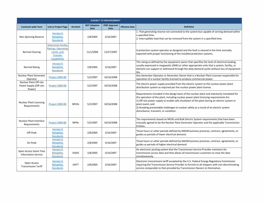
Continent-wide Term Link to Project Page Acronym BOT Adoption Date
FERC Approval Date
Effective Date Definition
SUBJECT TO ENFORCEMENT
Non-Spinning ReserveVersion 0 Reliability Standards
2/8/2005 3/16/2007
1. That generating reserve not connected to the system but capable of serving demand within a specified time.2. Interruptible load that can be removed from the system in a specified time.
Normal Clearing
Determine Facility Ratings, Operating
Limits, and Transfer
Capabilities
11/1/2006 12/27/2007A protection system operates as designed and the fault is cleared in the time normally expected with proper functioning of the installed protection systems.
Normal RatingVersion 0 Reliability Standards
2/8/2005 3/16/2007
The rating as defined by the equipment owner that specifies the level of electrical loading, usually expressed in megawatts (MW) or other appropriate units that a system, facility, or element can support or withstand through the daily demand cycles without loss of equipment life.
Nuclear Plant Generator Operator
Project 2009-08 5/2/2007 10/16/2008 Any Generator Operator or Generator Owner that is a Nuclear Plant Licensee responsible for operation of a nuclear facility licensed to produce commercial power.
Nuclear Plant Off-site Power Supply (Off-site
Power)Project 2009-08 5/2/2007 10/16/2008 The electric power supply provided from the electric system to the nuclear power plant
distribution system as required per the nuclear power plant license.
Nuclear Plant Licensing Requirements
Project 2009-08 NPLRs 5/2/2007 10/16/2008
Requirements included in the design basis of the nuclear plant and statutorily mandated for the operation of the plant, including nuclear power plant licensing requirements for: 1) Off-site power supply to enable safe shutdown of the plant during an electric system or plant event; and2) Avoiding preventable challenges to nuclear safety as a result of an electric system disturbance, transient, or condition.
Nuclear Plant Interface Requirements
Project 2009-08 NPIRs 5/2/2007 10/16/2008The requirements based on NPLRs and Bulk Electric System requirements that have been mutually agreed to by the Nuclear Plant Generator Operator and the applicable Transmission Entities.
Off-PeakVersion 0 Reliability Standards
2/8/2005 3/16/2007 Those hours or other periods defined by NAESB business practices, contract, agreements, or guides as periods of lower electrical demand.
On-PeakVersion 0 Reliability Standards
2/8/2005 3/16/2007 Those hours or other periods defined by NAESB business practices, contract, agreements, or guides as periods of higher electrical demand.
Open Access Same Time Information Service
Version 0 Reliability Standards
OASIS 2/8/2005 3/16/2007An electronic posting system that the Transmission Service Provider maintains for transmission access data and that allows all transmission customers to view the data simultaneously.
Open Access Transmission Tariff
Version 0 Reliability Standards
OATT 2/8/2005 3/16/2007Electronic transmission tariff accepted by the U.S. Federal Energy Regulatory Commission requiring the Transmission Service Provider to furnish to all shippers with non-discriminating service comparable to that provided by Transmission Owners to themselves.
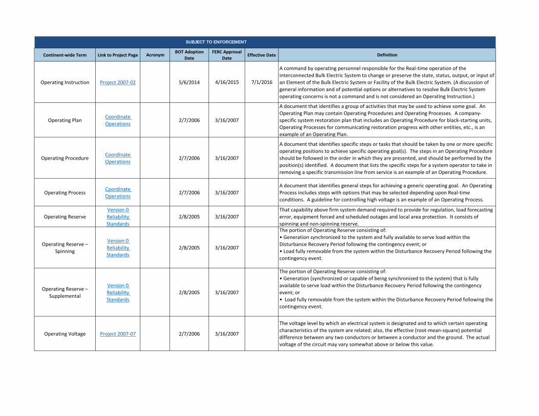
Continent-wide Term Link to Project Page Acronym BOT Adoption Date
FERC Approval Date
Effective Date Definition
SUBJECT TO ENFORCEMENT
Operating Instruction Project 2007-02 5/6/2014 4/16/2015 7/1/2016
A command by operating personnel responsible for the Real-time operation of the interconnected Bulk Electric System to change or preserve the state, status, output, or input of an Element of the Bulk Electric System or Facility of the Bulk Electric System. (A discussion of general information and of potential options or alternatives to resolve Bulk Electric System operating concerns is not a command and is not considered an Operating Instruction.)
Operating PlanCoordinate Operations
2/7/2006 3/16/2007
A document that identifies a group of activities that may be used to achieve some goal. An Operating Plan may contain Operating Procedures and Operating Processes. A company-specific system restoration plan that includes an Operating Procedure for black-starting units, Operating Processes for communicating restoration progress with other entities, etc., is an example of an Operating Plan.
Operating ProcedureCoordinate Operations
2/7/2006 3/16/2007
A document that identifies specific steps or tasks that should be taken by one or more specific operating positions to achieve specific operating goal(s). The steps in an Operating Procedure should be followed in the order in which they are presented, and should be performed by the position(s) identified. A document that lists the specific steps for a system operator to take in removing a specific transmission line from service is an example of an Operating Procedure.
Operating ProcessCoordinate Operations
2/7/2006 3/16/2007A document that identifies general steps for achieving a generic operating goal. An Operating Process includes steps with options that may be selected depending upon Real-time conditions. A guideline for controlling high voltage is an example of an Operating Process.
Operating ReserveVersion 0 Reliability Standards
2/8/2005 3/16/2007That capability above firm system demand required to provide for regulation, load forecasting error, equipment forced and scheduled outages and local area protection. It consists of spinning and non-spinning reserve.
Operating Reserve – Spinning
Version 0 Reliability Standards
2/8/2005 3/16/2007
The portion of Operating Reserve consisting of:• Generation synchronized to the system and fully available to serve load within the
Disturbance Recovery Period following the contingency event; or• Load fully removable from the system within the Disturbance Recovery Period following the
contingency event.
Operating Reserve – Supplemental
Version 0 Reliability Standards
2/8/2005 3/16/2007
The portion of Operating Reserve consisting of:• Generation (synchronized or capable of being synchronized to the system) that is fully
available to serve load within the Disturbance Recovery Period following the contingency event; or• Load fully removable from the system within the Disturbance Recovery Period following the
contingency event.
Operating Voltage Project 2007-07 2/7/2006 3/16/2007
The voltage level by which an electrical system is designated and to which certain operating characteristics of the system are related; also, the effective (root-mean-square) potential difference between any two conductors or between a conductor and the ground. The actual voltage of the circuit may vary somewhat above or below this value.

Continent-wide Term Link to Project Page Acronym BOT Adoption Date
FERC Approval Date
Effective Date Definition
SUBJECT TO ENFORCEMENT
Operational Planning Analysis
Project 2014-03 OPA 11/13/2014 11/19/2015 1/1/2017
An evaluation of projected system conditions to assess anticipated (pre-Contingency) and potential (post-Contingency) conditions for next-day operations. The evaluation shall reflect applicable inputs including, but not limited to, load forecasts; generation output levels; Interchange; known Protection System and Special Protection System status or degradation; Transmission outages; generator outages; Facility Ratings; and identified phase angle and equipment limitations. (Operational Planning Analysis may be provided through internal systems or through third-party services.)
Operations Support Personnel
Project 2010-01 2/6/2014 6/19/2014 7/1/2016Individuals who perform current day or next day outage coordination or assessments, or who determine SOLs, IROLs, or operating nomograms,1 in direct support of Real-time operations of the Bulk Electric System.
Outage Transfer Distribution Factor
Project 2006-07 ATC/TTC/AFC and
CBM/TRM Revisions
OTDF 8/22/2008 11/24/2009 In the post-contingency configuration of a system under study, the electric Power Transfer Distribution Factor (PTDF) with one or more system Facilities removed from service (outaged).
Overlap Regulation Service
Version 0 Reliability Standards
2/8/2005 3/16/2007A method of providing regulation service in which the Balancing Authority providing the regulation service incorporates another Balancing Authority’s actual interchange, frequency response, and schedules into providing Balancing Authority’s AGC/ACE equation.
Participation Factors
Project 2006-07 ATC/TTC/AFC and
CBM/TRM Revisions
8/22/2008 11/24/2009A set of dispatch rules such that given a specific amount of load to serve, an approximate generation dispatch can be determined. To accomplish this, generators are assigned a percentage that they will contribute to serve load.
Peak DemandVersion 0 Reliability Standards
2/8/2005 3/16/2007
1. The highest hourly integrated Net Energy For Load within a Balancing Authority Area occurring within a given period (e.g., day, month, season, or year). 2. The highest instantaneous demand within the Balancing Authority Area.
Performance-Reset Period
Determine Facility Ratings, Operating
Limits, and Transfer
Capabilities
2/7/2006 3/16/2007 The time period that the entity being assessed must operate without any violations to reset the level of non compliance to zero.
Physical Access Control Systems
Project 2008-06 Cyber Security
Order 706PACS 11/26/2012 11/22/2013 7/1/2016
Cyber Assets that control, alert, or log access to the Physical Security Perimeter(s), exclusive of locally mounted hardware or devices at the Physical Security Perimeter such as motion sensors, electronic lock control mechanisms, and badge readers.
Physical Security Perimeter
Project 2008-06 Cyber Security
Order 706PSP 11/26/2012 11/22/2013 7/1/2016 The physical border surrounding locations in which BES Cyber Assets, BES Cyber Systems, or
Electronic Access Control or Monitoring Systems reside, and for which access is controlled.
Planning Assessment
Project 2006-02 Assess
Transmission Future Needs and
Develop Transmission
Plans
8/4/2011 10/17/2013 1/1/2015 Documented evaluation of future Transmission System performance and Corrective Action Plans to remedy identified deficiencies.

Continent-wide Term Link to Project Page Acronym BOT Adoption Date
FERC Approval Date
Effective Date Definition
SUBJECT TO ENFORCEMENT
Planning AuthorityProject 2015-04
Alignment of Terms
11/5/2015 1/21/2016 7/1/2016 The responsible entity that coordinates and integrates transmission Facilities and service plans, resource plans, and Protection Systems.
Planning Coordinator
Project 2006-07 ATC/TTC/AFC and
CBM/TRM Revisions
PC 8/22/2008 11/24/2009 See Planning Authority.
Point of DeliveryVersion 0 Reliability Standards
POD 2/8/2005 3/16/2007 A location that the Transmission Service Provider specifies on its transmission system where an Interchange Transaction leaves or a Load-Serving Entity receives its energy.
Point of ReceiptProject 2015-04
Alignment of Terms
POR 11/5/2015 1/21/2016 7/1/2016 A location that the Transmission Service Provider specifies on its transmission system where an Interchange Transaction enters or a generator delivers its output.
Point to Point Transmission Service
Version 0 Reliability Standards
PTP 2/8/2005 3/16/2007 The reservation and transmission of capacity and energy on either a firm or non-firm basis from the Point(s) of Receipt to the Point(s) of Delivery.
Power Transfer Distribution Factor
Project 2006-07 ATC/TTC/AFC and
CBM/TRM Revisions
PTDF 8/22/2008 11/24/2009
In the pre-contingency configuration of a system under study, a measure of the responsiveness or change in electrical loadings on transmission system Facilities due to a change in electric power transfer from one area to another, expressed in percent (up to 100%) of the change in power transfer
Pro Forma TariffVersion 0 Reliability Standards
2/8/2005 3/16/2007 Usually refers to the standard OATT and/or associated transmission rights mandated by the U.S. Federal Energy Regulatory Commission Order No. 888.
Protected Cyber Assets Project 2014-02 PCA 2/12/2015 1/21/2016 7/1/2016
One or more Cyber Assets connected using a routable protocol within or on an Electronic Security Perimeter that is not part of the highest impact BES Cyber System within the same Electronic Security Perimeter. The impact rating of Protected Cyber Assets is equal to the highest rated BES Cyber System in the same ESP.
Protection System
Project 2007-17 Protection System Maintenance and
Testing
11/19/2010 2/3/2012 4/1/2013
Protection System – • Protective relays which respond to electrical quantities,
• Communications systems necessary for correct operation of protective functions
• Voltage and current sensing devices providing inputs to protective relays,
• Station dc supply associated with protective functions (including station batteries, battery
chargers, and non-battery-based dc supply), and• Control circuitry associated with protective functions through the trip coil(s) of the circuit
breakers or other interrupting devices.

Continent-wide Term Link to Project Page Acronym BOT Adoption Date
FERC Approval Date
Effective Date Definition
SUBJECT TO ENFORCEMENT
Protection System Maintenance Program
(PRC-005-6)
Project 2007-17.4 PRC-005 FERC Order No 803
Directive
PSMP 11/5/2015 12/18/2015 1/1/2016
An ongoing program by which Protection System,Automatic Reclosing, and Sudden Pressure Relaying Components are kept in working order and properoperation of malfunctioning Components is restored. A maintenance program for a specific Component includes one or more of the following activities:• Verify — Determine that the Component is functioning correctly.
• Monitor — Observe the routine in-service operation of the Component.
• Test — Apply signals to a Component to observe functional performance or output behavior,
or to diagnose problems.• Inspect — Examine for signs of Component failure, reduced performance or degradation.
• Calibrate — Adjust the operating threshold or measurement accuracy of a measuring
element to meet the intended performance requirement.
Pseudo-Tie Project 2008-12 2/6/2014 6/30/2014 10/1/2014A time-varying energy transfer that is updated in Real-time and included in the Actual Net Interchange term (NIA) in the same manner as a Tie Line in the affected Balancing Authorities’ control ACE equations (or alternate control processes).
Purchasing-Selling EntityVersion 0 Reliability Standards
PSE 2/8/2005 3/16/2007The entity that purchases or sells, and takes title to, energy, capacity, and Interconnected Operations Services. Purchasing-Selling Entities may be affiliated or unaffiliated merchants and may or may not own generating facilities.
Ramp Rateor
Ramp
Version 0 Reliability Standards
2/8/2005 3/16/2007(Schedule) The rate, expressed in megawatts per minute, at which the interchange schedule is attained during the ramp period.(Generator) The rate, expressed in megawatts per minute, that a generator changes its output.
Rated Electrical Operating Conditions
Project 2007-07 Transmission Vegetation
Management
2/7/2006 3/16/2007 The specified or reasonably anticipated conditions under which the electrical system or an individual electrical circuit is intend/designed to operate
RatingVersion 0 Reliability Standards
2/8/2005 3/16/2007 The operational limits of a transmission system element under a set of specified conditions.
Rated System Path Methodology
Project 2006-07 ATC/TTC/AFC and
CBM/TRM Revisions
8/22/2008 11/24/2009
The Rated System Path Methodology is characterized by an initial Total Transfer Capability (TTC), determined via simulation. Capacity Benefit Margin, Transmission Reliability Margin, and Existing Transmission Commitments are subtracted from TTC, and Postbacks and counterflows are added as applicable, to derive Available Transfer Capability. Under the Rated System Path Methodology, TTC results are generally reported as specific transmission path capabilities.
Reactive PowerProject 2015-04
Alignment of Terms
11/5/2015 1/21/2016 7/1/2016
The portion of electricity that establishes and sustains the electric and magnetic fields of alternating-current equipment. Reactive Power must be supplied to most types of magnetic equipment, such as motors and transformers. It also must supply the reactive losses on transmission facilities. Reactive Power is provided by generators, synchronous condensers, or electrostatic equipment such as capacitors and directly influences electric system voltage. It is usually expressed in kilovars (kvar) or megavars (Mvar).

Continent-wide Term Link to Project Page Acronym BOT Adoption Date
FERC Approval Date
Effective Date Definition
SUBJECT TO ENFORCEMENT
Real PowerProject 2015-04
Alignment of Terms
11/5/2015 1/21/2016 7/1/2016 The portion of electricity that supplies energy to the Load.
Real-time Coordinate Operations
2/7/2006 3/16/2007Present time as opposed to future time. (From Interconnection Reliability Operating Limits standard.)
Real-time Assessment Project 2014-03 11/13/2014Revised
definition. 11/19/2015
1/1/2017
An evaluation of system conditions using Real-time data to assess existing (pre-Contingency) and potential (post-Contingency) operating conditions. The assessment shall reflect applicable inputs including, but not limited to: load, generation output levels, known Protection System and Special Protection System status or degradation, Transmission outages, generator outages, Interchange, Facility Ratings, and identified phase angle and equipment limitations. (Real-time Assessment may be provided through internal systems or through third-party services.)
Receiving Balancing Authority
Version 0 Reliability Standards
2/8/2005 3/16/2007 The Balancing Authority importing the Interchange.
Regional Reliability Organization
Version 0 Reliability Standards
RRO 2/8/2005 3/16/2007
1. An entity that ensures that a defined area of the Bulk Electric System is reliable, adequate and secure. 2. A member of the North American Electric Reliability Council. The Regional Reliability Organization can serve as the Compliance Monitor.
Regional Reliability PlanVersion 0 Reliability Standards
2/8/2005 3/16/2007The plan that specifies the Reliability Coordinators and Balancing Authorities within the Regional Reliability Organization, and explains how reliability coordination will be accomplished.
Regulating ReserveVersion 0 Reliability Standards
2/8/2005 3/16/2007 An amount of reserve responsive to Automatic Generation Control, which is sufficient to provide normal regulating margin.
Regulation Reserve Sharing Group
Project 2010-14.1 Phase 1
8/15/2013 4/16/2015 7/1/2016
A group whose members consist of two or more BalancingAuthorities that collectively maintain, allocate, and supply the Regulating Reserve required for all member Balancing Authorities to use in meeting applicable regulating standards.
Regulation ServiceVersion 0 Reliability Standards
2/8/2005 3/16/2007
The process whereby one Balancing Authority contracts to provide corrective response to all or a portion of the ACE of another Balancing Authority. The Balancing Authority providing the response assumes the obligation of meeting all applicable control criteria as specified by NERC for itself and the Balancing Authority for which it is providing the Regulation Service.
Reliability Adjustment Arranged Interchange
Project 2008-12 Coordinate Interchange Standards
2/6/2014 6/30/2014 10/1/2014 A request to modify a Confirmed Interchange or Implemented Interchange for reliability purposes.
Reliability Adjustment RFI
Project 2007-14 Coordinate
Interchange - Timing Table
10/29/2008 12/17/2009 Request to modify an Implemented Interchange Schedule for reliability purposes.
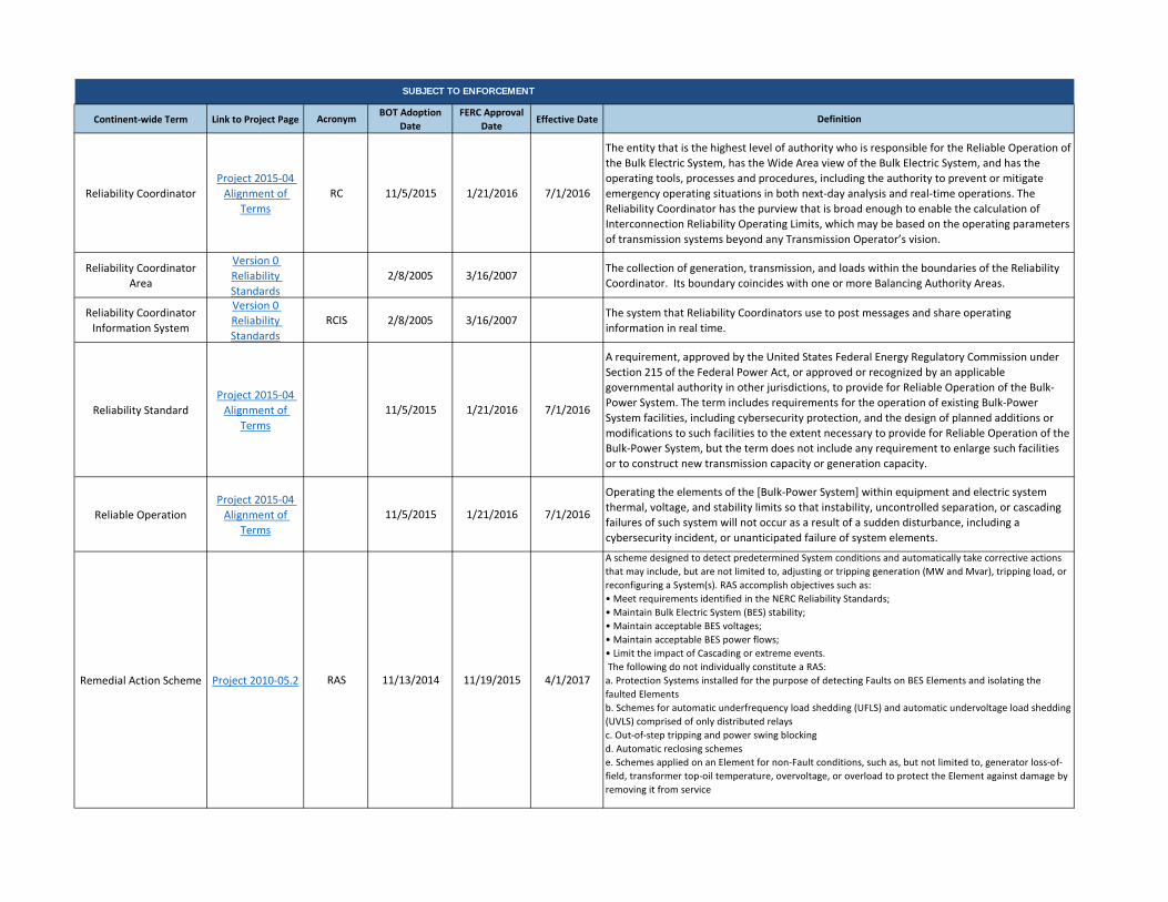
Continent-wide Term Link to Project Page Acronym BOT Adoption Date
FERC Approval Date
Effective Date Definition
SUBJECT TO ENFORCEMENT
Reliability CoordinatorProject 2015-04
Alignment of Terms
RC 11/5/2015 1/21/2016 7/1/2016
The entity that is the highest level of authority who is responsible for the Reliable Operation of the Bulk Electric System, has the Wide Area view of the Bulk Electric System, and has the operating tools, processes and procedures, including the authority to prevent or mitigate emergency operating situations in both next-day analysis and real-time operations. The Reliability Coordinator has the purview that is broad enough to enable the calculation of Interconnection Reliability Operating Limits, which may be based on the operating parameters of transmission systems beyond any Transmission Operator’s vision.
Reliability Coordinator Area
Version 0 Reliability Standards
2/8/2005 3/16/2007The collection of generation, transmission, and loads within the boundaries of the Reliability Coordinator. Its boundary coincides with one or more Balancing Authority Areas.
Reliability Coordinator Information System
Version 0 Reliability Standards
RCIS 2/8/2005 3/16/2007The system that Reliability Coordinators use to post messages and share operating information in real time.
Reliability Standard Project 2015-04
Alignment of Terms
11/5/2015 1/21/2016 7/1/2016
A requirement, approved by the United States Federal Energy Regulatory Commission under Section 215 of the Federal Power Act, or approved or recognized by an applicable governmental authority in other jurisdictions, to provide for Reliable Operation of the Bulk-Power System. The term includes requirements for the operation of existing Bulk-Power System facilities, including cybersecurity protection, and the design of planned additions or modifications to such facilities to the extent necessary to provide for Reliable Operation of the Bulk-Power System, but the term does not include any requirement to enlarge such facilities or to construct new transmission capacity or generation capacity.
Reliable OperationProject 2015-04
Alignment of Terms
11/5/2015 1/21/2016 7/1/2016
Operating the elements of the [Bulk-Power System] within equipment and electric system thermal, voltage, and stability limits so that instability, uncontrolled separation, or cascading failures of such system will not occur as a result of a sudden disturbance, including a cybersecurity incident, or unanticipated failure of system elements.
Remedial Action Scheme Project 2010-05.2 RAS 11/13/2014 11/19/2015 4/1/2017
A scheme designed to detect predetermined System conditions and automatically take corrective actions that may include, but are not limited to, adjusting or tripping generation (MW and Mvar), tripping load, or reconfiguring a System(s). RAS accomplish objectives such as: • Meet requirements identified in the NERC Reliability Standards;
• Maintain Bulk Electric System (BES) stability;
• Maintain acceptable BES voltages;
• Maintain acceptable BES power flows;
• Limit the impact of Cascading or extreme events.
The following do not individually constitute a RAS: a. Protection Systems installed for the purpose of detecting Faults on BES Elements and isolating the faulted Elements b. Schemes for automatic underfrequency load shedding (UFLS) and automatic undervoltage load shedding (UVLS) comprised of only distributed relays c. Out-of-step tripping and power swing blocking d. Automatic reclosing schemes e. Schemes applied on an Element for non-Fault conditions, such as, but not limited to, generator loss-of-field, transformer top-oil temperature, overvoltage, or overload to protect the Element against damage by removing it from service

Continent-wide Term Link to Project Page Acronym BOT Adoption Date
FERC Approval Date
Effective Date Definition
SUBJECT TO ENFORCEMENT
Remedial Action Scheme Continued
Project 2010-05.2 RAS 11/13/2014 11/19/2015 4/1/2017
f. Controllers that switch or regulate one or more of the following: series or shunt reactive devices, flexible alternating current transmission system (FACTS) devices, phase-shifting transformers, variable-frequency transformers, or tap-changing transformers; and, that are located at and monitor quantities solely at the same station as the Element being switched or regulated g. FACTS controllers that remotely switch static shunt reactive devices located at other stations to regulate the output of a single FACTS device h. Schemes or controllers that remotely switch shunt reactors and shunt capacitors for voltage regulation that would otherwise be manually switched i. Schemes that automatically de-energize a line for a non-Fault operation when one end of the line is open j. Schemes that provide anti-islanding protection (e.g., protect load from effects of being isolated with generation that may not be capable of maintaining acceptable frequency and voltage) k. Automatic sequences that proceed when manually initiated solely by a System Operator l. Modulation of HVdc or FACTS via supplementary controls, such as angle damping or frequency damping applied to damp local or inter-area oscillations m. Sub-synchronous resonance (SSR) protection schemes that directly detect sub-synchronous quantities (e.g., currents or torsional oscillations)
Remedial Action Scheme Continued
Project 2010-05.2 RAS 11/13/2014 11/19/2015 4/1/2017n. Generator controls such as, but not limited to, automatic generation control (AGC), generation excitation [e.g. automatic voltage regulation (AVR) and power system stabilizers (PSS)], fast valving, and speed governing
Removable Media Project 2014-02 2/12/2015 1/21/2016 7/1/2016
Storage media that (i) are not Cyber Assets, (ii) are capable of transferring executable code, (iii) can be used to store, copy, move, or access data, and (iv) are directly connected for 30 consecutive calendar days or less to a BES Cyber Asset, a network within an ESP, or a Protected Cyber Asset. Examples include, but are not limited to, floppy disks, compactdisks, USB flash drives, external hard drives, and other flash memory cards/drives that contain nonvolatile memory.
Reportable Cyber Security Incident
Project 2008-06 Cyber Security
Order 706 V5 CIP Standards
11/26/2012 11/22/2013 7/1/2016 A Cyber Security Incident that has compromised or disrupted one or more reliability tasks of a functional entity.
Reportable DisturbanceVersion 0 Reliability Standards
2/8/2005 3/16/2007
Any event that causes an ACE change greater than or equal to 80% of a Balancing Authority’s or reserve sharing group’s most severe contingency. The definition of a reportable disturbance is specified by each Regional Reliability Organization. This definition may not be retroactively adjusted in response to observed performance.

Continent-wide Term Link to Project Page Acronym BOT Adoption Date
FERC Approval Date
Effective Date Definition
SUBJECT TO ENFORCEMENT
Reporting ACE Project 2010-
14.2.1. Phase 22/11/2016 7/1/2016
The scan rate values of a Balancing Authority Area’s (BAA) Area Control Error (ACE) measured in MW includes the difference between the Balancing Authority Area’s Actual Net Interchange and its Scheduled Net Interchange, plus its Frequency Bias Setting obligation, plus correction for any known meter error. In the Western Interconnection, Reporting ACE includes Automatic Time Error Correction (ATEC).Reporting ACE is calculated as follows: Reporting ACE = (NIA − NIS) − 10B (FA − FS) – IME
Reporting ACE is calculated in the Western Interconnection as follows: Reporting ACE = (NIA − NIS) − 10B (FA − FS) – IME + IATEC
Where: • NIA = Actual Net Interchange. • NIS = Scheduled Net Interchange. • B = Frequency Bias Setting.
• FA = Actual Frequency. • FS = Scheduled Frequency. • IME = Interchange Meter Error. • IATEC = Automatic Time Error Correction.
Reporting ACE (continued)
Project 2010-14.2.1. Phase 2
2/11/2016 7/1/2016
All NERC Interconnections operate using the principles of Tie-line Bias (TLB) Control and require the use of an ACE equation similar to the Reporting ACE defined above. Any modification(s) to this specified Reporting ACE equation that is(are) implemented for all BAAs on an Interconnection and is(are) consistent with the following four principles of Tie Line Bias control will provide a valid alternative to this Reporting ACE equation: 1. All portions of the Interconnection are included in exactly one BAA so that the sum of all BAAs’ generation, load, and loss is the same as total Interconnection generation, load, and loss; 2. The algebraic sum of all BAAs’ Scheduled Net Interchange is equal to zero at all times and the sum of all BAAs’ Actual Net Interchange values is equal to zero at all times; 3. The use of a common Scheduled Frequency FS for all BAAs at all times; and, 4. Excludes metering or computational errors. (The inclusion and use of the IME term corrects for known metering or computational errors.)
Request for InterchangeProject 2008-12
Coordinate Interchange
RFI 2/6/2014 6/30/2014 10/1/2014A collection of data as defined in the NAESB Business Practice Standards submitted for the purpose of implementing bilateral Interchange between Balancing Authorities or an energy transfer within a single Balancing Authority.
Reserve Sharing GroupProject 2015-04
Alignment of Terms
11/5/2015 1/21/2016 7/1/2016
A group whose members consist of two or more Balancing Authorities that collectively maintain, allocate, and supply operating reserves required for each Balancing Authority’s use in recovering from contingencies within the group. Scheduling energy from an Adjacent Balancing Authority to aid recovery need not constitute reserve sharing provided the transaction is ramped in over a period the supplying party could reasonably be expected to load generation in (e.g., ten minutes). If the transaction is ramped in quicker (e.g., between zero and ten minutes) then, for the purposes of disturbance control performance, the areas become a Reserve Sharing Group.

Continent-wide Term Link to Project Page Acronym BOT Adoption Date
FERC Approval Date
Effective Date Definition
SUBJECT TO ENFORCEMENT
Reserve Sharing Group Reporting ACE
Project 2010-14.1 Phase 1
8/15/2013 4/16/2015
At any given time of measurement for the applicableReserve Sharing Group, the algebraic sum of the Reporting ACEs (or equivalent as calculated at such time of measurement) of the Balancing Authorities participating in the Reserve Sharing Group at the time of measurement.
Resource PlannerProject 2015-04
Alignment of Terms
11/5/2015 1/21/2016 7/1/2016The entity that develops a long-term (generally one year and beyond) plan for the resource adequacy of specific loads (customer demand and energy requirements) within a Planning Authority area.
Response RateVersion 0 Reliability Standards
2/8/2005 3/16/2007 The Ramp Rate that a generating unit can achieve under normal operating conditions expressed in megawatts per minute (MW/Min).
Right-of-Way Project 2010-07 ROW 5/9/2012 3/21/2013 7/1/2014
The corridor of land under a transmission line(s) needed to operate the line(s). The width of the corridor is established by engineering or construction standards as documented in either construction documents, pre-2007 vegetation maintenance records, or by the blowout standard in effect when the line was built. The ROW width in no case exceeds the applicable Transmission Owner’s or applicable Generator Owner’s legal rights but may be less based on the aforementioned criteria.
ScenarioCoordinate Operations
2/7/2006 3/16/2007 Possible event.
ScheduleVersion 0 Reliability Standards
2/8/2005 3/16/2007(Verb) To set up a plan or arrangement for an Interchange Transaction.(Noun) An Interchange Schedule.
Scheduled FrequencyVersion 0 Reliability Standards
2/8/2005 3/16/2007 60.0 Hertz, except during a time correction.
Scheduled Net Interchange (NIS)
Project 2010-14.2.1 Phase 2
2/11/2016 7/1/2016The algebraic sum of all scheduled megawatt transfers, including Dynamic Schedules, to and from all Adjacent Balancing Authority areas within the same Interconnection, including the effect of scheduled ramps. Scheduled megawatt transfers on asynchronous DC tie lines directly connected to another Interconnection are excluded from Scheduled Net Interchange.
Scheduling EntityVersion 0 Reliability Standards
2/8/2005 3/16/2007 An entity responsible for approving and implementing Interchange Schedules.
Scheduling PathVersion 0 Reliability Standards
2/8/2005 3/16/2007 The Transmission Service arrangements reserved by the Purchasing-Selling Entity for a Transaction.
Sending Balancing Authority
Version 0 Reliability Standards
2/8/2005 3/16/2007 The Balancing Authority exporting the Interchange.
Sink Balancing Authority
Project 2008-12 Coordinate Interchange Standards
2/6/2014 6/30/2014 10/1/2014 The Balancing Authority in which the load (sink) is located for an Interchange Transaction and any resulting Interchange Schedule.

Continent-wide Term Link to Project Page Acronym BOT Adoption Date
FERC Approval Date
Effective Date Definition
SUBJECT TO ENFORCEMENT
Source Balancing Authority
Project 2008-12 Coordinate Interchange Standards
2/6/2014 6/30/2014 10/1/2014 The Balancing Authority in which the generation (source) is located for an Interchange Transaction and for any resulting Interchange Schedule.
Special Protection System(Remedial Action
Scheme)Project 2010-05.2 SPS 5/5/2016 6/23/2016 4/1/2017 See “Remedial Action Scheme”
Spinning ReserveVersion 0 Reliability Standards
2/8/2005 3/16/2007 Unloaded generation that is synchronized and ready to serve additional demand.
StabilityVersion 0 Reliability Standards
2/8/2005 3/16/2007The ability of an electric system to maintain a state of equilibrium during normal and abnormal conditions or disturbances.
Stability LimitVersion 0 Reliability Standards
2/8/2005 3/16/2007The maximum power flow possible through some particular point in the system while maintaining stability in the entire system or the part of the system to which the stability limit refers.
Supervisory Control and Data Acquisition
Version 0 Reliability Standards
SCADA 2/8/2005 3/16/2007 A system of remote control and telemetry used to monitor and control the transmission system.
Supplemental Regulation Service
Version 0 Reliability Standards
2/8/2005 3/16/2007A method of providing regulation service in which the Balancing Authority providing the regulation service receives a signal representing all or a portion of the other Balancing Authority’s ACE.
SurgeVersion 0 Reliability Standards
2/8/2005 3/16/2007 A transient variation of current, voltage, or power flow in an electric circuit or across an electric system.
Sustained Outage
Project 2007-07 Transmission Vegetation
Management
2/7/2006 3/16/2007The deenergized condition of a transmission line resulting from a fault or disturbance following an unsuccessful automatic reclosing sequence and/or unsuccessful manual reclosing procedure.
SystemVersion 0 Reliability Standards
2/8/2005 3/16/2007 A combination of generation, transmission, and distribution components.
System Operating LimitProject 2015-04
Alignment of Terms
SOL 11/5/2015 1/21/2016 7/1/2016
The value (such as MW, Mvar, amperes, frequency or volts) that satisfies the most limiting of the prescribed operating criteria for a specified system configuration to ensure operation within acceptable reliability criteria. System Operating Limits are based upon certain operating criteria. These include, but are not limited to: • Facility Ratings (applicable pre- and post-Contingency Equipment Ratings or Facility Ratings)
• transient stability ratings (applicable pre- and post- Contingency stability limits)
• voltage stability ratings (applicable pre- and post-Contingency voltage stability)
• system voltage limits (applicable pre- and post-Contingency voltage limits)

Continent-wide Term Link to Project Page Acronym BOT Adoption Date
FERC Approval Date
Effective Date Definition
SUBJECT TO ENFORCEMENT
System OperatorProject 2010-01
Training2/6/2014 6/19/2014 7/1/2016
An individual at a Control Center of a Balancing Authority, Transmission Operator, or Reliability Coordinator, who operates or directs the operation of the Bulk Electric System (BES) in Real-time.
TelemeteringVersion 0 Reliability Standards
2/8/2005 3/16/2007The process by which measurable electrical quantities from substations and generating stations are instantaneously transmitted to the control center, and by which operating commands from the control center are transmitted to the substations and generating stations.
Thermal RatingVersion 0 Reliability Standards
2/8/2005 3/16/2007The maximum amount of electrical current that a transmission line or electrical facility can conduct over a specified time period before it sustains permanent damage by overheating or before it sags to the point that it violates public safety requirements.
Tie Line Version 0 2/8/2005 3/16/2007 A circuit connecting two Balancing Authority Areas.
Tie Line BiasVersion 0 Reliability Standards
2/8/2005 3/16/2007A mode of Automatic Generation Control that allows the Balancing Authority to 1.) maintain its Interchange Schedule and 2.) respond to Interconnection frequency error.
Time ErrorVersion 0 Reliability Standards
2/8/2005 3/16/2007The difference between the Interconnection time measured at the Balancing Authority(ies) and the time specified by the National Institute of Standards and Technology. Time error is caused by the accumulation of Frequency Error over a given period.
Time Error CorrectionVersion 0 Reliability Standards
2/8/2005 3/16/2007 An offset to the Interconnection’s scheduled frequency to return the Interconnection’s Time Error to a predetermined value.
TLR (Transmission Loading Relief) Log
(NERC added the spelled out term for TLR Log for clarification purposes.)
Version 0 Reliability Standards
2/8/2005 3/16/2007
Report required to be filed after every TLR Level 2 or higher in a specified format. The NERC IDC prepares the report for review by the issuing Reliability Coordinator. After approval by the issuing Reliability Coordinator, the report is electronically filed in a public area of the NERC Web site.
Total Flowgate Capability
Project 2006-07 ATC/TTC/AFC and
CBM/TRM Revisions
TFC 8/22/2008 11/24/2009The maximum flow capability on a Flowgate, is not to exceed its thermal rating, or in the case of a flowgate used to represent a specific operating constraint (such as a voltage or stability limit), is not to exceed the associated System Operating Limit.
Total Internal DemandProject 2010-04 Demand Data
(MOD C)5/6/2014 2/19/2015 7/1/2016
The Demand of a metered system, which includes the Firm Demand, plus any controllable and dispatchable DSM Load and the Load due to the energy losses incurred within the boundary of the metered system.
Total Transfer CapabilityVersion 0 Reliability Standards
TTC 2/8/2005 3/16/2007The amount of electric power that can be moved or transferred reliably from one area to another area of the interconnected transmission systems by way of all transmission lines (or paths) between those areas under specified system conditions.
TransactionVersion 0 Reliability Standards
2/8/2005 3/16/2007 See Interchange Transaction.

Continent-wide Term Link to Project Page Acronym BOT Adoption Date
FERC Approval Date
Effective Date Definition
SUBJECT TO ENFORCEMENT
Transfer CapabilityVersion 0 Reliability Standards
2/8/2005 3/16/2007
The measure of the ability of interconnected electric systems to move or transfer power in a reliable manner from one area to another over all transmission lines (or paths) between those areas under specified system conditions. The units of transfer capability are in terms of electric power, generally expressed in megawatts (MW). The transfer capability from “Area A” to “Area B” is not g enerally equal to the transfer capability from “Area B” to “Area A.”
Transfer Distribution Factor
Version 0 Reliability Standards
2/8/2005 3/16/2007 See Distribution Factor.
Transient Cyber Asset Project 2014-02 2/12/2015 1/21/2016 7/1/2016
A Cyber Asset that (i) is capable of transmitting or transferringexecutable code, (ii) is not included in a BES Cyber System, (iii) is not a Protected Cyber Asset (PCA), and (iv) is directly connected (e.g., using Ethernet, serial, Universal Serial Bus, or wireless, including near field or Bluetooth communication) for 30 consecutive calendar days or less to a BES Cyber Asset, a network within an ESP, or a PCA. Examples include, but are not limited to, Cyber Assets used for data transfer, vulnerability assessment, maintenance, or troubleshootingpurposes.
TransmissionVersion 0 Reliability Standards
2/8/2005 3/16/2007An interconnected group of lines and associated equipment for the movement or transfer of electric energy between points of supply and points at which it is transformed for delivery to customers or is delivered to other electric systems.
Transmission ConstraintVersion 0 Reliability Standards
2/8/2005 3/16/2007 A limitation on one or more transmission elements that may be reached during normal or contingency system operations.
Transmission CustomerProject 2015-04
Alignment of Terms
11/5/2015 1/21/2016 7/1/2016
1. Any eligible customer (or its designated agent) that can or does execute a Transmission Service agreement or can or does receive Transmission Service. 2. Any of the following entities: Generator Owner, Load-Serving Entity, or Purchasing-Selling Entity.
Transmission Line
Project 2007-07 Transmission Vegetation
Management
2/7/2006 3/16/2007
A system of structures, wires, insulators and associated hardware that carry electric energy from one point to another in an electric power system. Lines are operated at relatively high voltages varying from 69 kV up to 765 kV, and are capable of transmitting large quantities of electricity over long distances.
Transmission OperatorProject 2015-04
Alignment of Terms
11/5/2015 1/21/2016 7/1/2016 The entity responsible for the reliability of its “local” transmission system, and that operates or directs the operations of the transmission Facilities.
Transmission Operator Area
Project 2006-07 ATC/TTC/AFC and
CBM/TRM Revisions
8/22/2008 11/24/2009 The collection of Transmission assets over which the Transmission Operator is responsible for operating.
Transmission OwnerProject 2015-04
Alignment of Terms
11/5/2015 1/21/2016 7/1/2016 The entity that owns and maintains transmission Facilities.

Continent-wide Term Link to Project Page Acronym BOT Adoption Date
FERC Approval Date
Effective Date Definition
SUBJECT TO ENFORCEMENT
Transmission PlannerProject 2015-04
Alignment of Terms
11/5/2015 1/21/2016 7/1/2016The entity that develops a long-term (generally one year and beyond) plan for the reliability (adequacy) of the interconnected bulk electric transmission systems within its portion of the Planning Authority area.
Transmission Reliability Margin
Version 0 Reliability Standards
2/8/2005 3/16/2007
The amount of transmission transfer capability necessary to provide reasonable assurance that the interconnected transmission network will be secure. TRM accounts for the inherent uncertainty in system conditions and the need for operating flexibility to ensure reliable system operation as system conditions change.
Transmission Reliability Margin Implementation
Document
Project 2006-07 ATC/TTC/AFC and
CBM/TRM Revisions
8/22/2008 11/24/2009A document that describes the implementation of a Transmission Reliability Margin methodology, and provides information related to a Transmission Operator’s calculation of TRM.
Transmission ServiceVersion 0 Reliability Standards
2/8/2005 3/16/2007Services provided to the Transmission Customer by the Transmission Service Provider to move energy from a Point of Receipt to a Point of Delivery.
Transmission Service Provider
Project 2015-04 Alignment of
TermsTSP 11/5/2015 1/21/2016 7/1/2016 The entity that administers the transmission tariff and provides Transmission Service to
Transmission Customers under applicable Transmission Service agreements.
Undervoltage Load Shedding Program
Project 2008-02 Undervoltage
Load Shedding & Underfrequency Load Shedding
UVLS Program 11/13/2014 11/19/2015 4/1/2017
An automatic load shedding program, consisting of distributed relays and controls, used to mitigate undervoltage conditions impacting the Bulk Electric System (BES), leading to voltage instability, voltage collapse, or Cascading. Centrally controlled undervoltage-based load shedding is not included.
Vegetation
Project 2007-07 Transmission Vegetation
Management
2/7/2006 3/16/2007 All plant material, growing or not, living or dead.
Vegetation Inspection Project 2010-07 5/9/2012 3/21/2013 7/1/2014
The systematic examination of vegetation conditions on a Right-of-Way and those vegetation conditions under the applicable Transmission Owner’s or applicable Generator Owner’s control that are likely to pose a hazard to the line(s) prior to the next planned maintenance or inspection. This may be combined with a general line inspection.
Wide AreaVersion 0 Reliability Standards
2/8/2005 3/16/2007The entire Reliability Coordinator Area as well as the critical flow and status information from adjacent Reliability Coordinator Areas as determined by detailed system studies to allow the calculation of Interconnected Reliability Operating Limits.
Year OneProject 2010-10 FAC Order 729
1/24/2011 11/17/2011
The first twelve month period that a Planning Coordinator or a Transmission Planner is responsible for assessing. For an assessment started in a given calendar year, Year One
includes the forecasted peak Load period for one of the following two calendar years. For example, if a Planning Assessment was started in 2011, then Year One includes the forecasted
peak Load period for either 2012 or 2013.
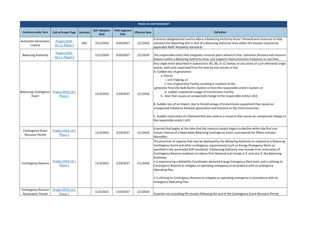
Continent-wide Term Link to Project Page AcronymBOT Adoption
DateFERC Approval
DateEffective Date Definition
Automatic Generation Control
Project 2010-14.2.1. Phase 2
AGC 2/11/2016 9/20/2017 1/1/2019A process designed and used to adjust a Balancing Authority Areas’ Demand and resources to help maintain the Reporting ACE in that of a Balancing Authority Area within the bounds required by applicable NERC Reliability Standards.
Balancing AuthorityProject 2010-
14.2.1. Phase 22/11/2016 9/20/2017 1/1/2019 The responsible entity that integrates resource plans ahead of time, maintains Demand and resource
balance within a Balancing Authority Area, and supports Interconnection frequency in real time.
Balancing Contingency Event
Project 2010-14.1 Phase 1
11/5/2015 1/19/2017 1/1/2018
Any single event described in Subsections (A), (B), or (C) below, or any series of such otherwise single events, with each separated from the next by one minute or less. A. Sudden loss of generation: a. Due to i. unit tripping, or ii. loss of generator Facility resulting in isolation of the generator from the Bulk Electric System or from the responsible entity’s System, or iii. sudden unplanned outage of transmission Facility; b. And, that causes an unexpected change to the responsible entity’s ACE;
B. Sudden loss of an Import, due to forced outage of transmission equipment that causes an unexpected imbalance between generation and Demand on the Interconnection.
C. Sudden restoration of a Demand that was used as a resource that causes an unexpected change to the responsible entity’s ACE.
Contingency Event Recovery Period
Project 2010-14.1 Phase 1
11/5/2015 1/19/2017 1/1/2018A period that begins at the time that the resource output begins to decline within the first one-minute interval of a Reportable Balancing Contingency Event, and extends for fifteen minutes thereafter.
Contingency Reserve Project 2010-14.1 Phase 1
11/5/2015 1/19/2017 1/1/2018
The provision of capacity that may be deployed by the Balancing Authority to respond to a Balancing Contingency Event and other contingency requirements (such as Energy Emergency Alerts as specified in the associated EOP standard). A Balancing Authority may include in its restoration of Contingency Reserve readiness to reduce Firm Demand and include it if, and only if, the Balancing Authority:• is experiencing a Reliability Coordinator declared Energy Emergency Alert level, and is utilizing its
Contingency Reserve to mitigate an operating emergency in accordance with its emergency Operating Plan.
• is utilizing its Contingency Reserve to mitigate an operating emergency in accordance with its
emergency Operating Plan.
Contingency Reserve Restoration Period
Project 2010-14.1 Phase 1
11/5/2015 1/19/2017 1/1/2018 A period not exceeding 90 minutes following the end of the Contingency Event Recovery Period.
PENDING ENFORCEMENT

Continent-wide Term Link to Project Page AcronymBOT Adoption
DateFERC Approval
DateEffective Date Definition
PENDING ENFORCEMENT
Most Severe Single Contingency
Project 2010-14.1 Phase 1
MSSC 11/5/2015 1/19/2017 1/1/2018
The Balancing Contingency Event, due to a single contingency identified using system models maintained within the Reserve Sharing Group (RSG) or a Balancing Authority’s area that is not part of a Reserve Sharing Group, that would result in the greatest loss (measured in MW) of resource output used by the RSG or a Balancing Authority that is not participating as a member of a RSG at the time of the event to meet Firm Demand and export obligation (excluding export obligation for which Contingency Reserve obligations are being met by the Sink Balancing Authority).
Operational Planning Analysis
Project 2007-06.2 Phase 2 of System
Protection Coordination
OPA 8/11/2016
An evaluation of projected system conditions to assess anticipated (pre-Contingency) and potential (post-Contingency) conditions for next-day operations. The evaluation shall reflect applicable inputs including, but not limited to: load forecasts; generation output levels; Interchange; known Protection System and Remedial Action Scheme status or degradation, functions, and limitations; Transmission outages; generator outages; Facility Ratings; and identified phase angle and equipment limitations.(Operational Planning Analysis may be provided through internal systems or through third-party services.)
Pre-Reporting Contingency Event
ACE Value
Project 2010-14.1 Phase 1
11/5/2015 1/19/2017 1/1/2018The average value of Reporting ACE, or Reserve Sharing Group Reporting ACE when applicable, in the 16-second interval immediately prior to the start of the Contingency Event Recovery Period based on EMS scan rate data.
Protection System Coordination Study
Project 2007-06 System Protection
Coordination
11/5/2015 An analysis to determine whether Protection Systems operate in the intended sequence during Faults.
Pseudo-TieProject 2010-
14.2.1. Phase 22/11/2016 9/20/2017 1/1/2019
A time-varying energy transfer that is updated in Real-time and included in the Actual Net Interchange term (NIA) in the same manner as a Tie Line in the affected Balancing Authorities’ Reporting ACE equation (or alternate control processes).
Real-time Assessment
Project 2007-06.2 Phase 2 of System
Protection Coordination
RTA 8/11/2016
An evaluation of system conditions using Real-time data to assess existing (pre-Contingency) and potential (post-Contingency) operating conditions. The assessment shall reflect applicable inputs including, but not limited to: load; generation output levels; known Protection System and Remedial Action Scheme status or degradation, functions, and limitations; Transmission outages; generator outages; Interchange; Facility Ratings; and identified phase angle and equipment limitations. (Realtime Assessment may be provided through internal systems or through third-party services.)
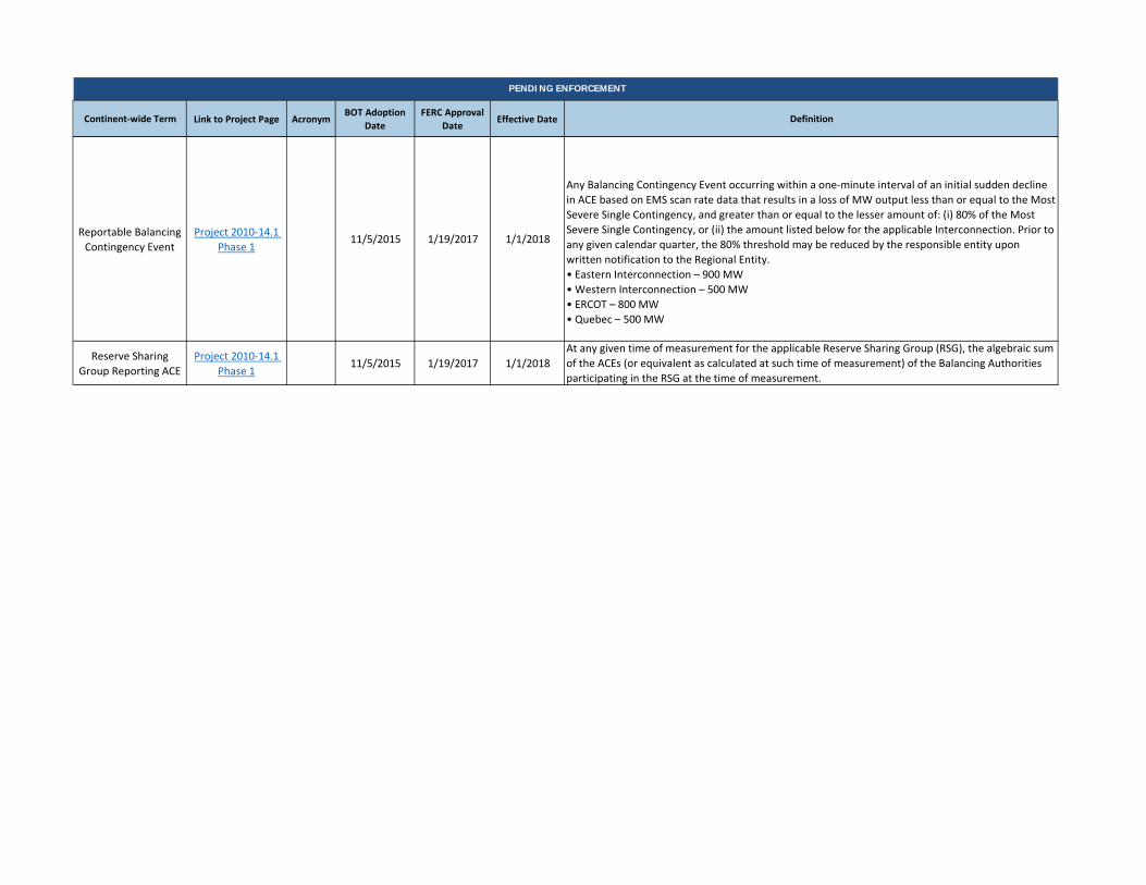
Continent-wide Term Link to Project Page AcronymBOT Adoption
DateFERC Approval
DateEffective Date Definition
PENDING ENFORCEMENT
Reportable Balancing Contingency Event
Project 2010-14.1 Phase 1
11/5/2015 1/19/2017 1/1/2018
Any Balancing Contingency Event occurring within a one-minute interval of an initial sudden decline in ACE based on EMS scan rate data that results in a loss of MW output less than or equal to the Most Severe Single Contingency, and greater than or equal to the lesser amount of: (i) 80% of the Most Severe Single Contingency, or (ii) the amount listed below for the applicable Interconnection. Prior to any given calendar quarter, the 80% threshold may be reduced by the responsible entity upon written notification to the Regional Entity. • Eastern Interconnection – 900 MW
• Western Interconnection – 500 MW
• ERCOT – 800 MW
• Quebec – 500 MW
Reserve Sharing Group Reporting ACE
Project 2010-14.1 Phase 1
11/5/2015 1/19/2017 1/1/2018At any given time of measurement for the applicable Reserve Sharing Group (RSG), the algebraic sum of the ACEs (or equivalent as calculated at such time of measurement) of the Balancing Authorities participating in the RSG at the time of measurement.

Continent-wide Term Link to Project Page Acronym BOT Adoption
DateFERC Approval
DateEffective Date Inactive Date Definition
Adjacent Balancing Authority
Version 0 Reliability Standards
2/8/2005 3/16/2007 9/30/2014A Balancing Authority Area that is interconnected another Balancing Authority Area either directly or via a multi-party agreement or transmission tariff.
Adverse Reliability Impact Project 2006-06 8/4/2011NERC withdrew
the related petition
The impact of an event that results in Bulk Electric System instability or Cascading.
Area Control ErrorVersion 0 Reliability Standards
ACE 2/8/2005 3/16/2007 3/31/2014The instantaneous difference between a Balancing Authority’s net actual and scheduled interchange, taking into account the effects of Frequency Bias and correction for meter error.
Arranged InterchangeCoordinate Interchange
5/2/2006 3/16/2007 9/30/2014 The state where the Interchange Authority has received the Interchange information (initial or revised).
ATC Path Project 2006-07 8/22/2008Not approved; Modification
directed
Any combination of Point of Receipt and Point of Delivery for which ATC is calculated; and any Posted Path. (See 18 CFR 37.6(b)(1))
Available Transfer Capability
Version 0 Reliability Standards
ATC 2/8/2005 3/16/2007
A measure of the transfer capability remaining in the physical transmissionnetwork for further commercial activity over and above already committeduses. It is defined as Total Transfer Capability less existing transmissioncommitments (including retail customer service), less a Capacity BenefitMargin, less a Transmission Reliability Margin.
BES Cyber Asset Project 2008-06 11/26/2012 11/22/2013 6/30/2016
A Cyber Asset that if rendered unavailable, degraded, or misused would, within 15 minutes of its required operation, misoperation, or non-operation, adversely impact one or more Facilities, systems, or equipment, which, if destroyed, degraded, or otherwise rendered unavailable when needed, would affect the reliable operation of the Bulk Electric System. Redundancy of affected Facilities, systems, and equipment shall not be considered when determining adverse impact. Each BES Cyber Asset is included in one or more BES Cyber Systems. (A Cyber Asset is not a BES Cyber Asset if, for 30 consecutive calendar days or less, it is directly connected to a network within an ESP, a Cyber Asset within an ESP, or to a BES Cyber Asset, and it is used for data transfer, vulnerability assessment, maintenance, or troubleshooting purposes.)
Blackstart Capability PlanVersion 0 Reliability Standards
2/8/2005 3/16/2007
7/1/2013Will be retired
when EOP-005-2 becomes
enforceable
A documented procedure for a generating unit or station to go from a shutdown condition to an operating condition delivering electric power without assistance from the electric system. This procedure is only a portion of an overall system restoration plan.
Blackstart Resource Project 2006-03 8/5/2009 3/17/2011 6/30/2016
A generating unit(s) and its associated set of equipment which has the ability to be started without support from the System or is designed to remain energized without connection to the remainder of the System, with the ability to energize a bus, meeting the Transmission Operator’s restoration plan needs for real and reactive power capability, frequency and voltage control, and that has been included in the Transmission Operator’s restoration plan.
RETIRED TERMS

Continent-wide Term Link to Project Page Acronym BOT Adoption
DateFERC Approval
DateEffective Date Inactive Date Definition
RETIRED TERMS
Bulk Electric SystemVersion 0 Reliability Standards
BES 2/8/2005 3/16/2007 6/30/2014
As defined by the Regional Reliability Organization, the electrical generation resources, transmission lines, interconnections with neighboring systems, and associated equipment, generally operated at voltages of 100 kV or higher. Radial transmission facilities serving only load with one transmission source are generally not included in this definition.
Bulk Electric System
(FERC issued an order on April 18, 2013 approving
the revised definition with an effective date of July 1, 2013. On June 14,
2013, FERC granted NERC’s request to extend the effective date of the revised definition of the Bulk Electric System to
July 1, 2014.)
Project 2010-17 BES 1/18/2012 6/14/2013
Replaced by BES definition FERC
approved 3/20/2014
Unless modified by the lists shown below, all Transmission Elements operated at 100 kV or higher and Real Power and Reactive Power resources connected at 100 kV or higher. This does not include facilities used in the local distribution of electric energy. Inclusions: • I1 - Transformers with the primary terminal and at least one secondary terminal
operated at 100 kV or higher unless excluded under Exclusion E1 or E3.• I2 - Generating resource(s) with gross individual nameplate rating greater than 20
MVA or gross plant/facility aggregate nameplate rating greater than 75 MVA including the generator terminals through the high-side of the step-up transformer(s) connected at a voltage of 100 kV or above.• I3 - Blackstart Resources identified in the Transmission Operator’s restoration plan.
• I4 - Dispersed power producing resources with aggregate capacity greater than 75
MVA (gross aggregate nameplate rating) utilizing a system designed primarily for aggregating capacity, connected at a common point at a voltage of 100 kV or above.
Bulk Electric System (Continued)
Project 2010-17 BES 1/18/2012 6/14/2013
Replaced by BES definition FERC
approved 3/20/2014
I5 –Static or dynamic devices (excluding generators) dedicated to supplying or absorbing Reactive Power that are connected at 100 kV or higher, or through a dedicated transformer with a high-side voltage of 100 kV or higher, or through a transformer that is designated in Inclusion I1.Exclusions: • E1 - Radial systems: A group of contiguous transmission Elements that emanates from a single point of connection of 100 kV or higher and:a) Only serves Load. Or,b) Only includes generation resources, not identified in Inclusion I3, with an aggregate capacity less than or equal to 75 MVA (gross nameplate rating). Or,c) Where the radial system serves Load and includes generation resources, not identified in Inclusion I3, with an aggregate capacity of non-retail generation less than or equal to 75 MVA (gross nameplate rating). Note – A normally open switching device between radial systems, as depicted on prints or one-line diagrams for example, does not affect this exclusion.

Continent-wide Term Link to Project Page Acronym BOT Adoption
DateFERC Approval
DateEffective Date Inactive Date Definition
RETIRED TERMS
Bulk Electric System (Continued)
Project 2010-17 BES 1/18/2012 6/14/2013
Replaced by BES definition FERC
approved 3/20/2014
• E2 - A generating unit or multiple generating units on the customer’s side of the retail meter that serve all or part of the retail Load with electric energy if: (i) the net capacity provided to the BES does not exceed 75 MVA, and (ii) standby, back-up, and maintenance power services are provided to the generating unit or multiple generating units or to the retail Load by a Balancing Authority, or provided pursuant to a binding obligation with a Generator Owner or Generator Operator, or under terms approved by the applicable regulatory authority.• E3 - Local networks (LN): A group of contiguous transmission Elements operated at or above 100 kV but less than 300 kV that distribute power to Load rather than transfer bulk power across the interconnected system. LN’s emanate from multiple points of connection at 100 kV or higher to improve the level of service to retail customer Load and not to accommodate bulk power transfer across the interconnected system. The LN is characterized by all of the following:
Bulk Electric System (Continued)
Project 2010-17 BES 1/18/2012 6/14/2013
Replaced by BES definition FERC
approved 3/20/2014
a) Limits on connected generation: The LN and its underlying Elements do not include generation resources identified in Inclusion I3 and do not have an aggregate capacity of non-retail generation greater than 75 MVA (gross nameplate rating);b) Power flows only into the LN and the LN does not transfer energy originating outside the LN for delivery through the LN; andc) Not part of a Flowgate or transfer path: The LN does not contain a monitored Facility of a permanent Flowgate in the Eastern Interconnection, a major transfer path within the Western Interconnection, or a comparable monitored Facility in the ERCOT or Quebec Interconnections, and is not a monitored Facility included in an Interconnection Reliability Operating Limit (IROL).• E4 – Reactive Power devices owned and operated by the retail customer
solely for its own use. Note - Elements may be included or excluded on a case-by-case basis through the Rules of Procedure exception process.
Bulk-Power System Project 2012-08.1 Phase 1
5/9/2013 7/9/2013 6/30/2016
A) facilities and control systems necessary for operating an interconnected electric energy transmission network (or any portion thereof); and (B) electric energy from generation facilities needed to maintain transmission system reliability. The term does not include facilities used in the local distribution of electric energy.

Continent-wide Term Link to Project Page Acronym BOT Adoption
DateFERC Approval
DateEffective Date Inactive Date Definition
RETIRED TERMS
Business Practices Project 2006-07 8/22/2008
Not approved;Modification
directed 11/24/2009
Those business rules contained in the Transmission Service Provider’s applicable tariff, rules, or procedures; associated Regional Reliability Organization or regional entity business practices; or NAESB Business Practices.
CascadingVersion 0 Reliability Standards
2/8/2005 3/16/2007 6/30/2016
The uncontrolled successive loss of system elements triggered by an incident at any location. Cascading results in widespread electric service interruption that cannot be restrained from sequentially spreading beyond an area predetermined by studies.
Cascading Outages
Determine Facility Ratings,
Operating Limits, and
Trasfer Capabilites
11/1/2006Withdrawn 2/12/2008
FERC Remanded 12/27/2007
The uncontrolled successive loss of Bulk Electric System Facilities triggered by an incident (or condition) at any location resulting in the interruption of electric service that cannot be restrained from spreading beyond a pre-
determined area.
Confirmed InterchangeCoordinate Interchange
5/2/2006 3/16/2007 The state where the Interchange Authority has verified the Arranged Interchange.
Critical AssetsCyber Security (Permanent)
5/2/2006 1/18/2008 6/30/2016Facilities, systems, and equipment which, if destroyed, degraded, or otherwise rendered unavailable, would affect the reliability or operability of the Bulk Electric System.
Critical Cyber AssetsCyber Security (Permanent)
5/2/2006 1/18/2008 6/30/2016 Cyber Assets essential to the reliable operation of Critical Assets.
Cyber AssetsCyber Security (Permanent)
5/2/2006 1/18/2008 6/30/2016 Programmable electronic devices and communication networks including hardware, software, and data.
Cyber Security IncidentCyber Security (Permanent)
5/2/2006 1/18/2008 6/30/2016
Any malicious act or suspicious event that:• Compromises, or was an attempt to compromise, the Electronic Security
Perimeter or Physical Security Perimeter of a Critical Cyber Asset, or, • Disrupts, or was an attempt to disrupt, the operation of a Critical Cyber
Asset.
Demand-Side Management
Version 0 Reliability Standards
DSM 2/8/2005 3/16/2007 6/30/2016 The term for all activities or programs undertaken by Load-Serving Entity or its customers to influence the amount or timing of electricity they use.
Distribution ProviderVersion 0 Reliability Standards
2/8/2005 3/16/2007 6/30/2016
Provides and operates the “wires” between the transmission system and the end-use customer. For those end-use customers who are served at transmission voltages, the Transmission Owner also serves as the Distribution Provider. Thus, the Distribution Provider is not defined by a specific voltage, but rather as performing the Distribution function at any voltage.
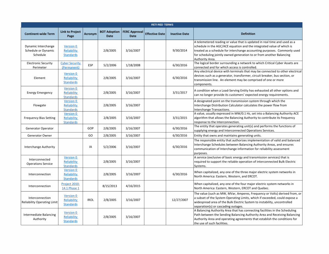
Continent-wide Term Link to Project Page Acronym BOT Adoption
DateFERC Approval
DateEffective Date Inactive Date Definition
RETIRED TERMS
Dynamic Interchange Schedule or Dynamic
Schedule
Version 0 Reliability Standards
2/8/2005 3/16/2007 9/30/2014
A telemetered reading or value that is updated in real time and used as a schedule in the AGC/ACE equation and the integrated value of which is treated as a schedule for interchange accounting purposes. Commonly used for scheduling jointly owned generation to or from another Balancing Authority Area.
Electronic Security Perimeter
Cyber Security (Permanent)
ESP 5/2/2006 1/18/2008 6/30/2016The logical border surrounding a network to which Critical Cyber Assets are connected and for which access is controlled.
ElementVersion 0 Reliability Standards
2/8/2005 3/16/2007 6/30/2016
Any electrical device with terminals that may be connected to other electrical devices such as a generator, transformer, circuit breaker, bus section, or transmission line. An element may be comprised of one or more components.
Energy EmergencyVersion 0 Reliability Standards
2/8/2005 3/16/2007 3/31/2017 A condition when a Load-Serving Entity has exhausted all other options and can no longer provide its customers’ expected energy requirements.
FlowgateVersion 0 Reliability Standards
2/8/2005 3/16/2007A designated point on the transmission system through which the Interchange Distribution Calculator calculates the power flow from Interchange Transactions.
Frequency Bias SettingVersion 0 Reliability Standards
2/8/2005 3/16/2007 3/31/2015A value, usually expressed in MW/0.1 Hz, set into a Balancing Authority ACE algorithm that allows the Balancing Authority to contribute its frequency response to the Interconnection.
Generator Operator GOP 2/8/2005 3/16/2007 6/30/2016The entity that operates generating unit(s) and performs the functions of supplying energy and Interconnected Operations Services.
Generator Owner GO 2/8/2005 3/16/2007 6/30/2016 Entity that owns and maintains generating units.
Interchange Authority IA 5/2/2006 3/16/2007 6/30/2016
The responsible entity that authorizes implementation of valid and balanced Interchange Schedules between Balancing Authority Areas, and ensures communication of Interchange information for reliability assessment purposes.
Interconnected Operations Service
Version 0 Reliability Standards
2/8/2005 3/16/2007A service (exclusive of basic energy and transmission services) that is required to support the reliable operation of interconnected Bulk Electric Systems.
InterconnectionVersion 0 Reliability Standards
2/8/2005 3/16/2007 6/30/2016 When capitalized, any one of the three major electric system networks in North America: Eastern, Western, and ERCOT.
InterconnectionProject 2010-14.1 Phase 1
8/15/2013 4/16/2015 When capitalized, any one of the four major electric system networks in North America: Eastern, Western, ERCOT and Quebec.
Interconnection Reliability Operating Limit
Version 0 Reliability Standards
IROL 2/8/2005 3/16/2007 12/27/2007
The value (such as MW, MVar, Amperes, Frequency or Volts) derived from, or a subset of the System Operating Limits, which if exceeded, could expose a widespread area of the Bulk Electric System to instability, uncontrolled separation(s) or cascading outages.
Intermediate Balancing Authority
Version 0 Reliability Standards
2/8/2005 3/16/2007
A Balancing Authority Area that has connecting facilities in the Scheduling Path between the Sending Balancing Authority Area and Receiving Balancing Authority Area and operating agreements that establish the conditions for the use of such facilities.

Continent-wide Term Link to Project Page Acronym BOT Adoption
DateFERC Approval
DateEffective Date Inactive Date Definition
RETIRED TERMS
Load-Serving EntityVersion 0 Reliability Standards
2/8/2005 3/16/2007Secures energy and transmission service (and related Interconnected Operations Services) to serve the electrical demand and energy requirements of its end-use customers.
Misoperation
Phase III - IV Planning
Standards - Archive
2/7/2006 3/16/2007 6/30/2016
• Any failure of a Protection System element to operate within the specified
time when a fault or abnormal condition occurs within a zone of protection. • Any operation for a fault not within a zone of protection (other than
operation as backup protection for a fault in an adjacent zone that is not cleared within a specified time for the protection for that zone). • Any unintentional Protection System operation when no fault or other
abnormal condition has occurred unrelated to on-site maintenance and testing activity.
Operational Planning Analysis
Operate Within Interconnection
Reliability Operating Limits
10/17/2008 3/17/2011 9/30/2014
An analysis of the expected system conditions for the next day’s operation. (That analysis may be performed either a day ahead or as much as 12 months ahead.) Expected system conditions include things such as load forecast(s), generation output levels, and known system constraints (transmission facility outages, generator outages, equipment limitations, etc.).
Operational Planning Analysis
Project 2008-12 2/6/2014 6/30/2014 10/1/2014 12/31/2016
An analysis of the expected system conditions for the next day’s operation. (That analysis may be performed either a day ahead or as much as 12 months ahead.) Expected system conditions include things such as load forecast(s), generation output levels, Interchange, and known system constraints (transmission facility outages, generator outages, equipment limitations, etc.).
Physical Security Perimeter
Cyber Security (Permanent)
PSP 5/2/2006 1/18/2008 6/30/2016The physical, completely enclosed (“six-wall”) border surrounding computer rooms, telecommunications rooms, operations centers, and other locations in which Critical Cyber Assets are housed and for which access is controlled.
Planning AuthorityVersion 0 Reliability Standards
PA 2/8/2005 3/16/2007 The responsible entity that coordinates and integrates transmission facility and service plans, resource plans, and protection systems.
Point of ReceiptVersion 0 Reliability Standards
POR 2/8/2005 3/16/2007 6/30/2016A location that the Transmission Service Provider specifies on its transmission system where an Interchange Transaction enters or a Generator delivers its output.
Postback
Project 2006-07 ATC/TTC/AFC
and CBM/TRM Revisions
8/22/2008
Not approved; Modification
directed 11/24/09
Positive adjustments to ATC or AFC as defined in Business Practices. Such Business Practices may include processing of redirects and unscheduled service.

Continent-wide Term Link to Project Page Acronym BOT Adoption
DateFERC Approval
DateEffective Date Inactive Date Definition
RETIRED TERMS
Protected Cyber Assets Project 2008-06 Cyber Security
Order 706PCA 11/26/2012 11/22/2013 6/30/2016
One or more Cyber Assets connected using a routable protocol within or on an Electronic Security Perimeter that is not part of the highest impact BES Cyber System within the same Electronic Security Perimeter. The impact rating of Protected Cyber Assets is equal to the highest rated BES Cyber System in the same ESP. A Cyber Asset is not a Protected Cyber Asset if, for 30 consecutive calendar days or less, it is connected either to a Cyber Asset within the ESP or to the network within the ESP, and it is used for data transfer, vulnerability assessment, maintenance, or troubleshooting purposes.
Protection System
Phase III-IV Planning
Standards - Archive
2/7/2006 3/17/2007 4/1/2013 Protective relays, associated communication systems, voltage and current sensing devices, station batteries and DC control circuitry.
Protection System Maintenance Program
(PRC-005-2)
Project 2007-17 Protection
System Maintenance and Testing
PSMP 11/7/2012 12/19/2013 4/1/2015
An ongoing program by which Protection System components are kept in working order and proper operation of malfunctioning components is restored. A maintenance program for a specific component includes one or more of the following activities: Verify — Determine that the component is functioning correctly.
Monitor — Observe the routine in-service operation of the component.
Test — Apply signals to a component to observe functional performance or
output behavior, or to diagnose problems. Inspect — Examine for signs of component failure, reduced performance or
degradation. Calibrate — Adjust the operating threshold or measurement accuracy of a
measuring element to meet the intended performance requirement.
Protection System Maintenance Program
(PRC-005-3)
Project 2007-17.2 Protection
System Maintenance and Testing -
Phase 2
PSMP 11/7/2013 1/22/2015 4/1/2016
An ongoing program by which Protection System and automatic reclosing components are kept in working order and proper operation of malfunctioning components is restored. A maintenance program for a specific component includes one or more of the following activities:Verify — Determine that the component is functioning correctly.
Monitor — Observe the routine in-service operation of the component.
Test — Apply signals to a component to observe functional performance or
output behavior, or to diagnose problems. Inspect — Examine for signs of component failure, reduced performance or
degradation. Calibrate — Adjust the operating threshold or measurement accuracy of a
measuring element to meet the intended performance requirement.

Continent-wide Term Link to Project Page Acronym BOT Adoption
DateFERC Approval
DateEffective Date Inactive Date Definition
RETIRED TERMS
Protection System Maintenance Program
(PRC-005-4)
Project 2014-01 Standards
Applicability for Dispersed
Generation Resources
PSMP 11/13/2014 9/17/2015 1/1/2016
An ongoing program by which Protection System, Automatic Reclosing, and Sudden Pressure Relaying Components are kept in working order and proper operation of malfunctioning Components is restored. A maintenance program for a specific Component includes one or more of the following activities: • Verify — Determine that the Component is functioning correctly.
• Monitor — Observe the routine in-service operation of the Component.
• Test — Apply signals to a Component to observe functional performance or
output behavior, or to diagnose problems. • Inspect — Examine for signs of Component failure, reduced performance or
degradation. • Calibrate — Adjust the operating threshold or measurement accuracy of a
measuring element to meet the intended performance requirement.
Pseudo-TieVersion 0 Reliability Standards
2/8/2005 3/16/2007A telemetered reading or value that is updated in real time and used as a “virtual” tie line flow in the AGC/ACE equation but for which no physical tie or energy metering actually exists. The integrated value is used as a metered
Reactive PowerVersion 0 Reliability Standards
2/8/2005 3/16/2007 6/30/2016
The portion of electricity that establishes and sustains the electric and magnetic fields of alternating-current equipment. Reactive power must be supplied to most types of magnetic equipment, such as motors and transformers. It also must supply the reactive losses on transmission facilities. Reactive power is provided by generators, synchronous condensers, or electrostatic equipment such as capacitors and directly influences electric system voltage. It is usually expressed in kilovars (kvar) or megavars (Mvar).
Real PowerVersion 0 Reliability Standards
2/8/2005 3/16/2007 The portion of electricity that supplies energy to the load.
ReallocationVersion 0 Reliability Standards
2/8/2005 3/16/2007 The total or partial curtailment of Transactions during TLR Level 3a or 5a to allow Transactions using higher priority to be implemented.
Real-time Assessment
Operate Within Interconnection
Reliability Operating Limits
10/17/2008 3/17/2011 12/31/2016 An examination of existing and expected system conditions, conducted by collecting and reviewing immediately available data

Continent-wide Term Link to Project Page Acronym BOT Adoption
DateFERC Approval
DateEffective Date Inactive Date Definition
RETIRED TERMS
Reliability CoordinatorVersion 0 Reliability Standards
RC 2/8/2005 3/16/2007 6/30/2007
The entity that is the highest level of authority who is responsible for the reliable operation of the Bulk Electric System, has the Wide Area view of the Bulk Electric System, and has the operating tools, processes and procedures, including the authority to prevent or mitigate emergency operating situations in both next-day analysis and real-time operations. The Reliability Coordinator has the purview that is broad enough to enable the calculation of Interconnection Reliability Operating Limits, which may be based on the operating parameters of transmission systems beyond any Transmission Operator’s vision.
Reliability DirectiveProject 2006-06
Reliability Coordination
8/16/2012 11/19/2015 11/19/2015
A communication initiated by a Reliability Coordinator,Transmission Operator, or Balancing Authority where action by the recipient is necessary to address an Emergency or Adverse Reliability Impact.
Reliability Standard
Project 2012-08.1 Phase 1 of
Glossary Updates: Statutory
Definitions
5/9/2013 7/9/2013 6/30/2016
A requirement, approved by the United States Federal Energy Regulatory Commission under this Section 215 of the Federal Power Act, or approved or recognized by an applicable governmental authority in other jurisdictions, to provide for reliable operation [Reliable Operation] of the bulk-power system [Bulk-Power System]. The term includes requirements for the operation of existing bulk-power system [Bulk-Power System] facilities, including cybersecurity protection, and the design of planned additions or modifications to such facilities to the extent necessary to provide for reliable operation [Reliable Operation] of the bulk-power system [Bulk-Power System], but the term does not include any requirement to enlarge such facilities or to construct new transmission capacity or generation capacity.
Reliable Operation
Project 2012-08.1 Phase 1 of
Glossary Updates: Statutory
Definitions
5/9/2013 7/9/2013 6/30/2016
Operating the elements of the bulk-power system [Bulk-Power System] within equipment and electric system thermal, voltage, and stability limits so that instability, uncontrolled separation, or cascading failures of such system will not occur as a result of a sudden disturbance, including a cybersecurity incident, or unanticipated failure of system elements.
Remedial Action SchemeVersion 0 Reliability Standards
RAS 2/8/2005 3/16/2007 3/31/2017 See “Special Protection System”

Continent-wide Term Link to Project Page Acronym BOT Adoption
DateFERC Approval
DateEffective Date Inactive Date Definition
RETIRED TERMS
Reporting Ace 8/15/20134/16/2015
(Will not go into effect)
The scan rate values of a Balancing Authority’s Area Control Error (ACE) measured in MW, which includes the difference between the Balancing Authority’s Net Actual Interchange and its Net Scheduled Interchange, plus its Frequency Bias obligation, plus any known meter error. In the Western Interconnection, Reporting ACE includes Automatic Time Error Correction (ATEC).Reporting ACE is calculated as follows:Reporting ACE = (NIA − NIS) − 10B (FA − FS) − IME
Reporting ACE is calculated in the Western Interconnection as follows:Reporting ACE = (NIA − NIS) − 10B (FA − FS) − IME + IATEC
Where:NIA (Actual Net Interchange) is the algebraic sum of actual megawatt transfers across all Tie Lines and includes Pseudo-Ties. Balancing Authorities directly connected via asynchronous ties to another Interconnection may include or exclude megawatt transfers on those Tie lines in their actual interchange, provided they are implemented in the same manner for Net Interchange Schedule.NIS (Scheduled Net Interchange) is the algebraic sum of all scheduled megawatt transfers, including Dynamic Schedules, with adjacent Balancing Authorities, and taking into account the effects of schedule ramps. Balancing Authorities directly connected via asynchronous ties to another Interconnection may include or exclude megawatttransfers on those Tie Lines in their scheduled Interchange, provided they are implemented in the same manner for Net Interchange Actual.
Reporting Ace (Continued) 8/15/2013
4/16/2015 (Will not go into effect)
B (Frequency Bias Setting) is the Frequency Bias Setting (in negative MW/0.1 Hz) for the Balancing Authority.10 is the constant factor that converts the frequency bias setting units to MW/Hz.FA (Actual Frequency) is the measured frequency in Hz.FS (Scheduled Frequency) is 60.0 Hz, except during a time correction.IME (Interchange Meter Error) is the meter error correction factor and represents the difference between the integrated hourly average of the net interchange actual (NIA) and the cumulative hourly net Interchange energy measurement (in megawatt-hours).IATEC (Automatic Time Error Correction) is the addition of a component to the ACE equation for the Western Interconnection that modifies the control point for thepurpose of continuously paying back Primary Inadvertent Interchange to correct accumulated time error. Automatic Time Error Correction is only applicable in the Western Interconnection.
ATEC shall be zero when operating in any other AGC mode.• Y = B / BS.
• H = Number of hours used to payback Primary Inadvertent Interchange energy. The
value of H is set to 3.

Continent-wide Term Link to Project Page Acronym BOT Adoption
DateFERC Approval
DateEffective Date Inactive Date Definition
RETIRED TERMS
Reporting Ace (Continued)
energy. The value of H is set to 3.BS = Frequency Bias for the Interconnection (MW / 0.1 Hz).• Primary Inadvertent Interchange (PIIhourly) is (1-Y) * (IIactual - B * ΔTE/6)
• IIactual is the hourly Inadvertent Interchange for the last hour.• ΔTE is the hourly change in system Time Error as distributed by the Interconnection
Time Monitor. Where:ΔTE = TEend hour – TEbegin hour – TDadj – (t)*(TEoffset)• TDadj is the Reliability Coordinator adjustment for differences with Interconnection Time Monitor control center clocks.• t is the number of minutes of Manual Time Error Correction that occurred during the
hour.• TEoffset is 0.000 or +0.020 or -0.020.• PIIaccum is the Balancing Authority’s accumulated PIIhourly in MWh. An On-Peak and Off-Peak accumulation accounting is required.Where:
All NERC Interconnections with multiple Balancing Authorities operate using the
Reporting Ace (Continued) 8/15/2013
4/16/2015 (Will not go into effect)
All NERC Interconnections with multiple Balancing Authorities operate using theprinciples of Tie-line Bias (TLB) Control and require the use of an ACE equationsimilar to the Reporting ACE defined above. Any modification(s) to this specifiedReporting ACE equation that is(are) implemented for all Balancing Authorities onan interconnection and is(are) consistent with the following four principles willprovide a valid alternative Reporting ACE equation consistent with the measures included in this standard.
1. All portions of the Interconnection are included in one area or another so that the sum of all area generation, loads and losses is the same as total system generation, load and losses. 2. The algebraic sum of all area Net Interchange Schedules and all Net Interchange actual values is equal to zero at all times.3. The use of a common Scheduled Frequency FS for all areas at all times.4. The absence of metering or computational errors. (The inclusion and use of the IME term to account for known metering or computational errors.)
Request for InterchangeCoordinate Interchange
RFI 5/2/2006 3/16/2007A collection of data as defined in the NAESB RFI Datasheet, to be submitted to the Interchange Authority for the purpose of implementing bilateral Interchange between a Source and Sink Balancing Authority.
Reserve Sharing GroupVersion 0 Reliability Standards
RSG 2/8/2005 3/16/2007 6/30/2016
A group whose members consist of two or more Balancing Authorities that collectively maintain, allocate, and supply operating reserves required for each Balancing Authority’s use in recovering from contingencies within the group. Scheduling energy from an Adjacent Balancing Authority to aid recovery need not constitute reserve sharing provided the transaction is ramped in over a period the supplying party could reasonably be expected to load generation in (e.g., ten minutes). If the transaction is ramped in quicker (e.g., between zero and ten minutes) then, for the purposes of Disturbance Control Performance, the Areas become a Reserve Sharing Group.

Continent-wide Term Link to Project Page Acronym BOT Adoption
DateFERC Approval
DateEffective Date Inactive Date Definition
RETIRED TERMS
Resource PlannerVersion 0 Reliability Standards
RP 2/8/2005 3/16/2007The entity that develops a long-term (generally one year and beyond) plan for the resource adequacy of specific loads (customer demand and energy requirements) within a Planning Authority Area.
Right-of-Way Project 2007-07 ROW 2/7/2006 3/16/2007A corridor of land on which electric lines may be located. The Transmission Owner may own the land in fee, own an easement, or have certain franchise, prescription, or license rights to construct and maintain lines.
Right-of-Way Project 2007-07 ROW 11/3/2011 3/21/2013 6/30/2014
The corridor of land under a transmission line(s) needed to operate the line(s). The width of the corridor is established by engineering or construction standards as documented in either construction documents, pre-2007 vegetation maintenance records, or by the blowout standard in effect when the line was built. The ROW width in no case exceeds the Transmission Owner’s legal rights but may be less based on the aforementioned criteria.
Sink Balancing AuthorityVersion 0 Reliability Standards
2/8/2005 3/16/2007 9/30/2014The Balancing Authority in which the load (sink) is located for an Interchange Transaction. (This will also be a Receiving Balancing Authority for the resulting Interchange Schedule.)
Source Balancing Authority
Version 0 Reliability Standards
2/8/2005 3/16/2007 9/30/2014The Balancing Authority in which the generation (source) is located for an Interchange Transaction. (This will also be a Sending Balancing Authority for the resulting Interchange Schedule.)
Special Protection System(Remedial Action
Scheme)
Version 0 Reliability Standards
SPS 2/8/2005
3/16/2007 (Becomes inactive
3/31/2017)
3/31/2017
An automatic protection system designed to detect abnormal or predetermined system conditions, and take corrective actions other than and/or in addition to the isolation of faulted components to maintain system reliability. Such action may include changes in demand, generation (MW and Mvar), or system configuration to maintain system stability, acceptable voltage, or power flows. An SPS does not include (a) underfrequency or undervoltage load shedding or (b) fault conditions that must be isolated or (c) out-of-step relaying (not designed as an integral part of an SPS). Also called Remedial Action Scheme.
System Operating LimitVersion 0 Reliability Standards
SOL 2/8/2005 3/16/2007 6/30/2014
The value (such as MW, MVar, Amperes, Frequency or Volts) that satisfies the most limiting of the prescribed operating criteria for a specified system configuration to ensure operation within acceptable reliability criteria. System Operating Limits are based upon certain operating criteria. These include, but are not limited to:• Facility Ratings (Applicable pre- and post-Contingency equipment or facility
ratings)• Transient Stability Ratings (Applicable pre- and post-Contingency Stability
Limits)• Voltage Stability Ratings (Applicable pre- and post-Contingency Voltage
Stability)• System Voltage Limits (Applicable pre- and post-Contingency Voltage
Limits)
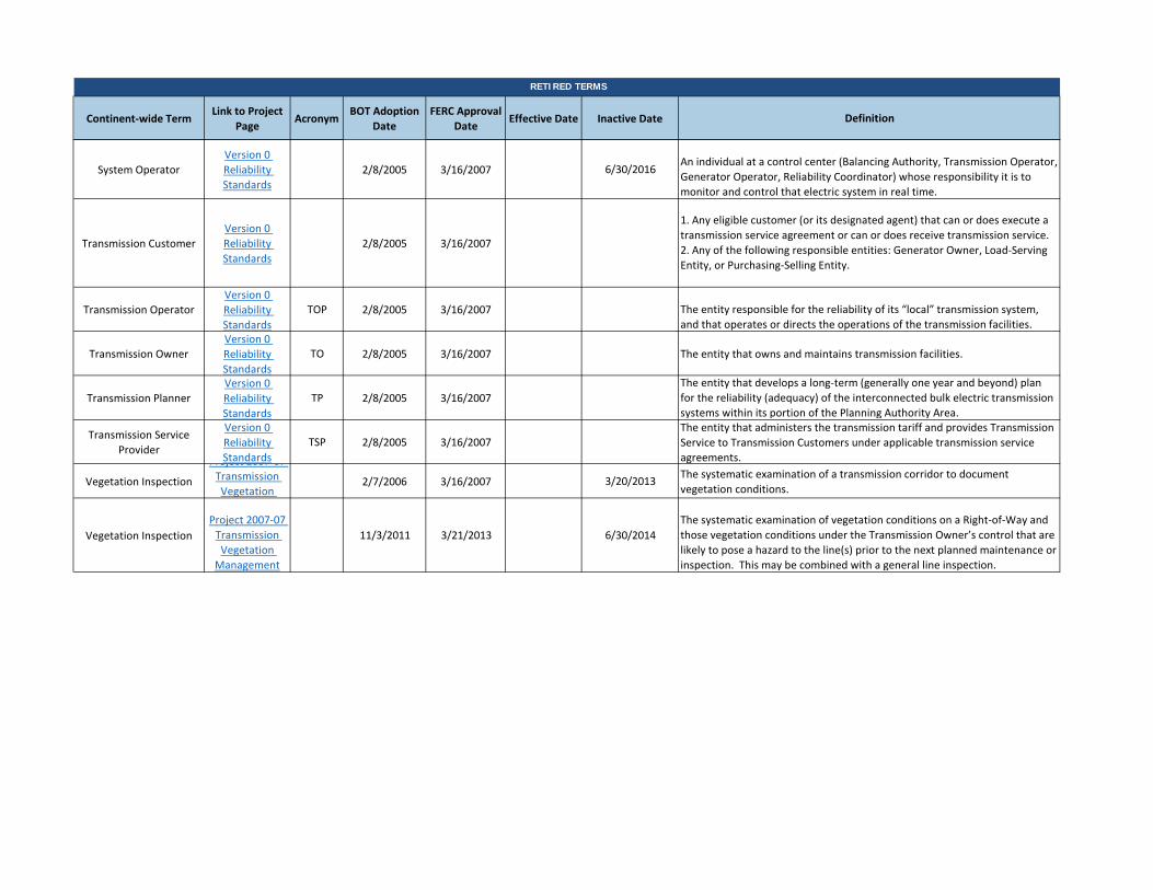
Continent-wide Term Link to Project Page Acronym BOT Adoption
DateFERC Approval
DateEffective Date Inactive Date Definition
RETIRED TERMS
System OperatorVersion 0 Reliability Standards
2/8/2005 3/16/2007 6/30/2016An individual at a control center (Balancing Authority, Transmission Operator, Generator Operator, Reliability Coordinator) whose responsibility it is to monitor and control that electric system in real time.
Transmission CustomerVersion 0 Reliability Standards
2/8/2005 3/16/2007
1. Any eligible customer (or its designated agent) that can or does execute a transmission service agreement or can or does receive transmission service. 2. Any of the following responsible entities: Generator Owner, Load-Serving Entity, or Purchasing-Selling Entity.
Transmission OperatorVersion 0 Reliability Standards
TOP 2/8/2005 3/16/2007 The entity responsible for the reliability of its “local” transmission system, and that operates or directs the operations of the transmission facilities.
Transmission OwnerVersion 0 Reliability Standards
TO 2/8/2005 3/16/2007 The entity that owns and maintains transmission facilities.
Transmission PlannerVersion 0 Reliability Standards
TP 2/8/2005 3/16/2007The entity that develops a long-term (generally one year and beyond) plan for the reliability (adequacy) of the interconnected bulk electric transmission systems within its portion of the Planning Authority Area.
Transmission Service Provider
Version 0 Reliability Standards
TSP 2/8/2005 3/16/2007The entity that administers the transmission tariff and provides Transmission Service to Transmission Customers under applicable transmission service agreements.
Vegetation Inspection
Project 2007 07 Transmission Vegetation
2/7/2006 3/16/2007 3/20/2013 The systematic examination of a transmission corridor to document vegetation conditions.
Vegetation InspectionProject 2007-07
Transmission Vegetation
Management
11/3/2011 3/21/2013 6/30/2014The systematic examination of vegetation conditions on a Right-of-Way and those vegetation conditions under the Transmission Owner’s control that are likely to pose a hazard to the line(s) prior to the next planned maintenance or inspection. This may be combined with a general line inspection.

NPCC Regional Term Link to Implementation Plan AcronymBOT
Adoption Date
FERC Approval
Date
Effective Date
Inactive Date
Definition
Current Zero TimePRC-002-NPCC-1 Implementation
Plan 11/4/2010 10/20/2011 10/20/2013 The time of the final current zero on the last phase to interrupt.
Generating PlantPRC-002-NPCC-1 Implementation
Plan11/4/2010 10/20/2011 10/20/2013 One or more generators at a single physical location whereby any single
contingency can affect all the generators at that location.
RELIABILITYFIRST Regional Term
Link to FERC Order AcronymBOT
Adoption Date
FERC Approval
Date
Effective Date
Inactive Date
Definition
Resource Adequacy BAL-502-RFC-02 Implementation Plan
8/5/2009 3/17/2011 The ability of supply-side and demand-side resources to meet the aggregate electrical demand (including losses)
Net Internal Demand BAL-502-RFC-02 Implementation Plan
8/5/2009 3/17/2011Total of all end-use customer demand and electric system losses within specified metered boundaries, less Direct Control Management and Interruptible Demand
Peak Period BAL-502-RFC-02 Implementation Plan
8/5/2009 3/17/2011A period consisting of two (2) or more calendar months but less than seven (7) calendar months, which includes the period during which the responsible entity’s annual peak demand is expected to occur
Wind Generating Station
BAL-502-RFC-02 Implementation Plan
11/3/2011 (Board
withdrew approval
11/7/2012)
3/17/2011
A collection of wind turbines electrically connected together and injecting energy into the grid at one point, sometimes known as a “Wind Farm.”
Year OneBAL-502-RFC-02 Implementation
Plan8/5/2009 3/17/2011 The planning year that begins with the upcoming annual Peak Period
NPCC REGIONAL DEFINITIONS
RELIABILITYFIRST REGIONAL DEFINITIONS

Frequency Measurable Event
BAL-001-TRE-1 Implementation Plan
FME 8/15/2013 1/16/2014 4/1/2014
An event that results in a Frequency Deviation, identified at the BA’s sole discretion, and meeting one of the following conditions:
i) a Frequency Deviation that has a pre-perturbation [the 16-second period of time before t(0)] average frequency to post-perturbation [the 32-second period of time starting 20 seconds after t(0)] average frequency absolute deviation greater than 100 mHz (the 100 mHz value may be adjusted by the BA to capture 30 to 40 events per year).
Or
ii) a cumulative change in generating unit/generating facility, DC tie and/or firm load pre-perturbation megawatt value to post-perturbation megawatt value absolute deviation greater than 550 MW (the 550 MW value may be adjusted by the BA to capture 30 to 40 events per year).
Governor 8/15/2013 1/16/2014 4/1/2014
The electronic, digital or mechanical device that implements Primary Frequency Response of generating units/generatingfacilities or other system elements.
Primary Frequency Response
BAL-001-TRE-1 Implementation Plan
PFR 8/15/2013 1/16/2014 4/1/2014 Primary Frequency Response of generating units/generating
WECC Regional Term WECC Standards Under Development Acronym
BOT Adoption
Date
FERC Approval
Date
Effective Date
Inactive Date
Definition
Area Control Error *WECC Regional Standards Under
DevelopmentACE 3/12/2007 6/8/2007 3/31/2014
Means the instantaneous difference between net actual and scheduled interchange, taking into account the effects of Frequency Bias including correction for meter error.
Automatic Generation Control *
WECC Regional Standards Under Development
AGC 3/12/2007 6/8/2007Means equipment that automatically adjusts a Control Area’s generation from a central location to maintain its interchange schedule plus Frequency Bias.
Automatic Time Error Correction
WECC Regional Standards Under Development
3/26/2008 5/21/2009 3/31/2014A frequency control automatic action that a Balancing Authority uses to offset its frequency contribution to support the Interconnection’s scheduled frequency.
Automatic Time Error Correction
WECC Regional Standards Under Development
12/19/2012 10/16/2013 4/1/2014The addition of a component to the ACE equation that modifies the control point for the purpose of continuously paying back Primary Inadvertent Interchange to correct accumulated time error.
Average Generation *WECC Regional Standards Under
Development3/12/2007 6/8/2007
Means the total MWh generated within the Balancing Authority Operator’s Balancing Authority Area during the prior year divided by 8760 hours (8784 hours if the prior year had 366 days).
Business Day * WECC Regional Standards Under Development
3/12/2007 6/8/2007Means any day other than Saturday, Sunday, or a legal public holiday as designated in section 6103 of title 5, U.S. Code.
WECC REGIONAL DEFINITIONS
TEXAS RE REGIONAL DEFINITIONS

Commercial OperationWECC Regional Standards Under
Development10/29/2008 4/21/2011
Achievement of this designation indicates that theGenerator Operator or Transmission Operator of the synchronous generator or synchronous condenser has received all approvals necessary for operation after completion of initial start-up testing.
Contributing ScheduleWECC Regional Standards Under
Development2/10/2009 3/17/2011
A Schedule not on the Qualified Transfer Path between a Source Balancing Authority and a Sink Balancing Authority that contributes unscheduled flow across the Qualified Transfer Path.
Dependability-Based Misoperation
WECC Regional Standards Under Development
10/29/2008 4/21/2011Is the absence of a Protection System or RAS operation when intended. Dependability is a component of reliability and is the measure of a device’s certainty to operate when required.
Disturbance *WECC Regional Standards Under
Development3/12/2007 6/8/2007 Retired
Means (i) any perturbation to the electric system, or (ii) the unexpected change in ACE that is caused by the sudden loss of generation or interruption of load.
Extraordinary Contingency†
WECC Regional Standards Under Development
3/12/2007 6/8/2007
Shall have the meaning set out in Excuse of Performance, section B.4.c.language in section B.4.c:means any act of God, actions by a non-affiliated third party, labor disturbance, act of the public enemy, war, insurrection, riot, fire, storm or flood, earthquake, explosion, accident to or breakage, failure or malfunction of machinery or equipment, or any other cause beyond the Reliability Entity’s reasonable control; provided that prudent industry standards (e.g. maintenance, design, operation) have been employed; and provided further that no act or cause shall be considered an Extraordinary Contingency if such act or cause results in any contingency contemplated in any WECC Reliability Standard (e.g., the “Most Severe Single Contingency” as defined in the WECC Reliability Criteria or any lesser contingency).
WECC Regional Term WECC Standards Under Development Acronym
BOT Adoption
Date
FERC Approval
Date
Effective Date
Inactive Date
Definition
Frequency Bias *WECC Regional Standards Under
Development3/12/2007 6/8/2007
Means a value, usually given in megawatts per 0.1 Hertz, associated with a Control Area that relates the difference between scheduled and actual frequency to the amount of generation required to correct the difference.
Functionally Equivalent Protection System
WECC Regional Standards Under Development
FEPS 10/29/2008 4/21/2011
A Protection System that provides performance as follows:• Each Protection System can detect the same faults within the zone of
protection and provide the clearing times and coordination needed to comply with all Reliability Standards.• Each Protection System may have different components and operating
characteristics.
WECC REGIONAL DEFINITIONS

Functionally Equivalent RAS
WECC Regional Standards Under Development
FERAS 10/29/2008 4/21/2011
A Remedial Action Scheme (“RAS”) that provides the same performance as follows:• Each RAS can detect the same conditions and provide mitigation to
comply with all Reliability Standards.• Each RAS may have different components and operating characteristics.
Generating Unit Capability *
WECC Regional Standards Under Development
3/12/2007 6/8/2007 Means the MVA nameplate rating of a generator.
Non-spinning Reserve†WECC Regional Standards Under
Development3/12/2007 6/8/2007 Retired
Means that Operating Reserve not connected to the system but capable of serving demand within a specified time, or interruptible load that can be removed from the system in a specified time.
Normal Path Rating *WECC Regional Standards Under
Development3/12/2007 6/8/2007
Is the maximum path rating in MW that has been demonstrated to WECC through study results or actual operation, whichever is greater. For a path with transfer capability limits that vary seasonally, it is the maximum of all the seasonal values.
Operating Reserve *WECC Regional Standards Under
Development3/12/2007 6/8/2007
Means that capability above firm system demand required to provide for regulation, load-forecasting error, equipment forced and scheduled outages and local area protection. Operating Reserve consists of Spinning Reserve and Nonspinning Reserve.
Operating Transfer Capability Limit *
WECC Regional Standards Under Development
OTC 3/12/2007 6/8/2007
Means the maximum value of the most critical system operating parameter(s) which meets: (a) precontingency criteria as determined by equipment loading capability and acceptable voltage conditions, (b) transient criteria as determined by equipment loading capability and acceptable voltage conditions, (c) transient performance criteria, and (d) post-contingency loading and voltage criteria.
Primary Inadvertent Interchange
WECC Regional Standards Under Development
3/26/2008 5/21/2009 The component of area (n) inadvertent interchange caused by the regulating deficiencies of the area (n).
Qualified Controllable Device
WECC Regional Standards Under Development
2/10/2009 3/17/2011A controllable device installed in the Interconnection for controlling energy flow and the WECC Operating Committee has approved using the device for controlling the USF on the Qualified Transfer Paths.
Qualified Transfer Path WECC Regional Standards Under Development
2/10/2009 3/17/2011 A transfer path designated by the WECC Operating Committee as being qualified for WECC unscheduled flow mitigation.
Qualified Transfer Path Curtailment Event
WECC Regional Standards Under Development
2/10/2009 3/17/2011Each hour that a Transmission Operator calls for Step 4 or higher for one or more consecutive hours (See Attachment 1 IRO-006-WECC-1) during which the curtailment tool is functional.
WECC Regional Term WECC Standards Under Development Acronym
BOT Adoption
Date
FERC Approval
Date
Effective Date
Inactive Date
Definition
Relief Requirement WECC Regional Standards Under
Development2/10/2009 3/17/2011 6/30/2014
The expected amount of the unscheduled flow reduction on the Qualified Transfer Path that would result by curtailing each Sink Balancing Authority’s Contributing Schedules by the percentages listed in the columns of WECC Unscheduled Flow Mitigation Summary of Actions Table in Attachment 1 WECC IRO-006-WECC-1.
WECC REGIONAL DEFINITIONS

Relief Requirement WECC Regional Standards Under
Development2/7/2013 6/13/2014 7/1/2014
The expected amount of the unscheduled flow reduction on the Qualified Transfer Path that would result by curtailing each Sink Balancing Authority’s Contributing Schedules by the percentages determined in the WECC unscheduled flow mitigation guideline.
Secondary Inadvertent Interchange
WECC Regional Standards Under Development
3/26/2008 5/21/2009 The component of area (n) inadvertent interchange caused by the regulating deficiencies of area (i).
Security-Based Misoperation
WECC Regional Standards Under Development
10/29/2008 4/21/2011A Misoperation caused by the incorrect operation of a Protection System or RAS. Security is a component of reliability and is the measure of a device’s certainty not to operate falsely.
Spinning Reserve† WECC Regional Standards Under Development
3/12/2007 6/8/2007 RetiredMeans unloaded generation which is synchronized and ready to serve additional demand. It consists of Regulating reserve and Contingency reserve (as each are described in Sections B.a.i and ii).
Transfer Distribution Factor
WECC Regional Standards Under Development
TDF 2/10/2009 3/17/2011
The percentage of USF that flows across a Qualified Transfer Path when an Interchange Transaction (Contributing Schedule) is implemented. [See the WECC Unscheduled Flow Mitigation Summary of Actions Table (Attachment 1 WECC IRO-006-WECC-1).]
WECC Table 2 *WECC Regional Standards Under
Development3/12/2007 6/8/2007
Means the table maintained by the WECC identifying those transfer paths monitored by the WECC regional Reliability coordinators. As of the date set out therein, the transmission paths identified in Table 2 are as listed in Attachment A to this Standard.
† FERC approved the WECC Tier One Reliability Standards in the Order Approving Regional Reliability Standards for the Western Interconnection and Directing Modifications, 119 FERC ¶ 61,260 (June 8, 2007). In that Order, FERC directed WECC to address the inconsistencies between the regional definitions and the NERC Glossary in developing permanent replacement standards. The replacement standards designed to address the shortcomings were filed with FERC in 2009.

Date Action
10/6/2017 Added the Effective date of Automatic Generation Control, Pseudo-Tie and Balancing Authority
8/1/2017Moved to Subject to Enforcement: Reporting Ace, Actual Frequency, Actual Net Interchange, Schedule Net Interchange, Interchange Meter Error, Automatic Time Error Correction
7/24/2017 Updated project link for definitions related to Project 2014-02, board adopted 2/12/15.
7/14/2017 Updated project link to Remedial Action Scheme with an effective date of 4/1/17; Removeable Media link to project 2014-02.
7/3/2017 Moved 'Geomagnetic Disturbance Vulnerability Assessment or GMD Vunerability Assessment' to Subject to Enforcement
6/15/2017 Readded 'Governor' and 'Primary Frequency Response' to TexasRE
4/4/2017Moved to Subject to Enforcement: Energy Emergency, Remedial Action Scheme, Special Protection System and Under3 Voltage Load Shedding Program. Moved terms inactive 3/31/17 to Retired tab.
3/16/2017 Removed Pending Inactive tab; not necessary3/10/2017 Added Pending Inactive tab
2/7/2017
Added Effective Dates for: Balancing Contingency Event, Most Severe Single Contingency (MSSC), Reportable Balancing Contingency Event, Contingency Event Recovery Period, Contingency Reserve Restoration Period, Pre-Reporting Contingency Event ACE Value, Reserve Sharing Group Reporting ACE, Contingency Reserve
1/25/2017 Removed WECC terms 'Non-Spinning Reserve' and 'Spinning Reserve' per FERC Order No. 789. Docket No. RM13-13-000.
1/6/2017 Moved the following terms from Pending Enforcement to Subject to Enforcement: Operational Planning Analysis, Real-time Assessment (Revised Definition)
1/5/2017 Formatting of Glossary of Terms updated.
12/12/16 Updated: 'Adverse Reliability Impact' from Pending to Retired. NERC withdrew the related petition 3/18/2015
11/28/16 Updated ReliabilityFirst - Wind Generating Station term to inactive
9/28/16Updated CIP v 5 standards effective date from 4/1/2016 to 7/1/2016 per FERC Order 822.
8/17/16 Board Adopted: Operational Planning Analysis and Real-time Assessment
7/13/16Updated color coding of terms retired 6/30/2016 based on the terms becoming effective 7/1/2016.FERC approved: Actual Frequency, Actual Net Interchange, Scheduled NetInterchange (NIS), Interchange Meter Error (IME), and Automatic Time Error Correction (ATEC)
CHANGE HISTORY
6/24/16

Reporting ACE: status updated
6/21/16Correction: Reserve Sharing Group Reporting ACE, and Contingency Reserve changed to 11/5/2015 Board adoption date status
4/1/16
Effective: BES Cyber Asset, BES Cyber System, BES Cyber System Information, CIP Exceptional Circumstance, CIP Senior Manager, Cyber Assets, Cyber Security Incident, Dial-up Connectivity, Electronic Access Control or Monitoring Systems, Electronic Access Point, Electronic Security Perimeter, External Routable Connectivity, Interactive Remote Access, Intermediate System, Physical Access Control Systems, Physical Security Perimeter
3/31/16Inactive: Critical Assets, Critical Cyber Assets, Cyber Assets, Cyber Security Incident, Electronic Security Perimeter, Physical Security Perimeter
6/24/16