novel design of symmetric photonic bandgap based image encryption
TRANSCRIPT
Progress In Electromagnetics Research C, Vol. 30, 225–239, 2012
NOVEL DESIGN OF SYMMETRIC PHOTONICBANDGAP BASED IMAGE ENCRYPTION SYSTEM
N. F. F. Areed and S. S. A. Obayya*
Department of Electronics and Communications Engineering, Facultyof Engineering, Mansoura University, Mansoura, Egypt
Abstract—A novel approach for the design of image encryptionsystem based on one stage of 3D photonic bandgap structure isproposed. Using the Finite Integration Time Domain (FITD) method,the performance of the proposed design is optimized through theutilization of the reflection properties from 3D photonic bandgapstructure while maintaining constant phase encoding. To demonstratethe robustness of the suggested encryption system, root mean squareerror is calculated between the original and decrypted images revealingthe high accuracy in retrieving the images. In addition, as the proposedsystem renders itself as easy to fabricate, it has an excellent potentialfor being very useful in both microwaves and photonics imaging systemapplications.
1. INTRODUCTION
Encryption is one of the most important and most affordable defensesavailable to protect our information, and most notably in securingour on-line data transmission from attack. Images are widely usedin several processes. Therefore, the protection of image data fromunauthorized access is important. Due to special characteristicsof image data, such as large data volumes, and high redundancy,sometimes image encryption techniques have their own requirementssuch as compression, format compliance, mean square error tolerance,etc. [1–3].
Traditionally, several methods can be used to encrypt image datastreams, some of which can be symmetric in which encryption anddecryption keys are the same, or asymmetric in which encryption anddecryption keys differ. Symmetric keys, however, usually encrypt more
Received 2 May 2012, Accepted 11 June 2012, Scheduled 22 June 2012* Corresponding author: Salah S. A. Obayya ([email protected]).
226 Areed and Obayya
efficiently, so they lend themselves to encrypting large amounts of dataand are likely to be even more secure than the asymmetric method [4].
Recently, optical security techniques have witnessed someadvances due to characteristics of parallelism and fast processors.Optics provides many degrees of freedom with which the opticalbeam may be encoded, such as amplitude, phase, wavelength, andpolarization. As a result, a number of schemes for optical encryptionhave been proposed such as amplitude-based encryption and full phaseencryption and polarization encoding encryption according to themethod of encoding input information [5–8]. Full phase encryptionusing phase encoded input information is lasting and more secure thanamplitude-based encryption due to the presence of additive noise andnonlinear characteristics of phase function. In ideal case the phaseinformation is not invisible and cannot be copied by an intensitydetector.
Double random phase encoding (DRPE), proposed by Refregierand Javidi [1], is considered as one of the most widely used opticalencryption techniques. Fractional Fourier transform (FRFT) [9] isproposed as a generalization of the conventional plane encodings.Optical Fourier Transform (OFT) plays an important role in opticalimage processing for encoding systems. In this regard, lenses are usedto perform OFT of an object in the DRPE technique. But lensessuffer from aberration which produces errors in the calculated Fouriertransform [10, 11].
Currently, there are many available developed approaches foroptical encryption systems. In one of them, the concept of modeson DRPE-type encryption systems has been introduced to analyze theencryption system in the context of known attacks [12]. Cryptographicblock ciphers partition messages into data blocks before transmission.These blocks are then processed, one at a time. The best way todo this is using the standard modes of operation along with thebasic cryptographic algorithm. These modes of operation can beused to pad in a more secure way, control error propagation, andtransform a block cipher into an arbitrary length stream cipher. Themain contribution of [12] is to present several modes of operationwith increased sophistication, that allow the sender some level ofdefense against the known attacks upon DRPE. Further radicallydifferent considerations for optical encryption based on the concepts ofcomputational ghost imaging have been proposed [13]. Ghost imagingis an intriguing optical technique where the imaging information isobtained through photon coincidence detection. The idea is based onsharing a secret key, consisting of a vector of N components betweenthe sender and the recipient, and a spatially coherent monochromatic

Progress In Electromagnetics Research C, Vol. 30, 2012 227
laser beam passes through an spatial light modulator, which introducesan arbitrary phase-only mask. The transmitted light is collectedby a single-pixel detector. This operation is repeated N timesfor N different phase profiles, each of them corresponding to onesecret key component. The encrypted version of the object image isnot a complex-valued matrix but simply an intensity vector, whichnoticeably reduces the number of transmitted bits. Moreover, a 3Dspace based approach is used as a new method for optical encryption invarious encryption architectures [14]. The fundamental feature of thisproposed method is that each pixel of the plaintext is axially translatedand considered as one particle in the proposed space-based opticalimage encryption, and the diffraction of all particles forms an objectwave in the phase-shifting digital holography. In [15], one of the latestdevelopments in the encryption technology is introduced which involvesa new method using a structured illumination based diffractive imagingwith a laterally translated phase grating for optical double-imagecryptography. In addition, the integration of the photon-countingimaging technique with optical encryption has been recently proposedto obtain a photon-limited version of the encrypted distribution [16].
In this work, a new idea for data-image encryption and decryptionis proposed. This idea relies on the use of 3D Photonic Band-Gap structures (PBG). Photonic band-gap structures are periodicstructures that are used to control many features of electromagneticradiation in certain bands of frequencies. The emerging technologyof one-dimensional (1D), two-dimensional (2D) and three-dimensional(3D) PBG structures can be suitably exploited to design and makeoptical devices such as waveguides, splitters, resonant cavities, filtersand so on [17–21]. Our proposed design adopts a carefully tailoredPBG block that exhibits high reflectivity and constant phase propertieswithin our frequency range of interest. The design of the proposed3D PBG encryptor depends actually on studying the relation betweenthe reflection properties and the geometrical parameters of the 1DPBG structure. The use of the 3D PBG enhances the securityof the encoding system as replacing the complicated encryption-decryption designs by only one stage of 3D hardware key. Also,wide bandwidth operation facilitates the correct sampling of thesignal and signal recovery for intruders challenging. To demonstratethe excellent performance of the proposed symmetric encryptionsystem, mean square error between the decrypted and original imagehas been calculated. Although used in microwave frequencies, theoffered design can be easily extended to optical frequency range viathe appropriate scaling of the system dimensions. Due to simplefabrication and yet significantly better performance, the designed PBG

228 Areed and Obayya
encryption/decryption approach renders itself as a highly competitiveapproach in comparison to recently existing encryption techniquesbased on diffraction gratings [22].
3D simulator based on Finite Integration Time Domain (FITD)algorithm was used for simulating the PBG structures. The FIDT is aconsistent formulation for the discrete representation of the integralform of Maxwell’s equations on spatial grids. First proposed byWeiland [23, 24] in 1977. The Perfect Boundary Approximation (PBA)technique that relies on non-uniform mesh applied in conjunction withFIT maintains all the advantages of the structured Cartesian grids,while allowing the accurate meshing around the curved boundaries: acrucial point for modeling PBG structure [25].
The paper is organized as follows. Following this introduction,some analysis and temporal response of the 1D PBG structureis given in Section 2. In Section 3 the generalized 3D PBGencryption/decryption structure is explained. Section 4 presents thesimulation results showing the performance of the proposed structurein encryption and decryption of image, Section 5 briefly presents themain conclusions of our study.
2. DESIGN CONCEPT
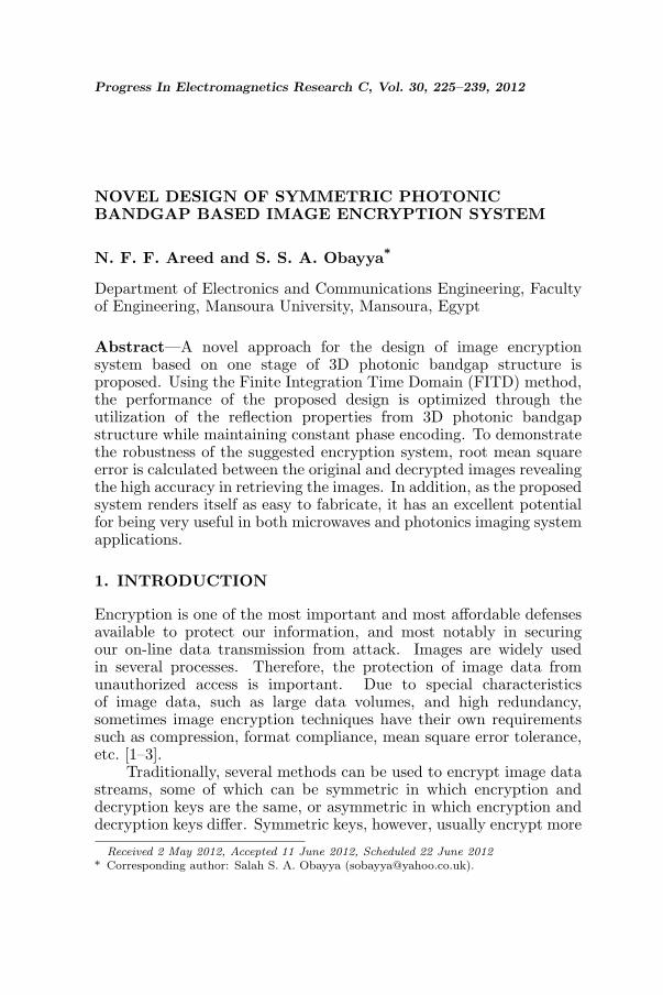
First, we consider a six periods of Bragg grating structure made ofRT/duroid 6010LM (εr = 10.8) excited by an electric mode locatedat the distance equal to 39mm from its boundary. According to thesimple equation relating the Bragg reflected wavelength, the effectiverefractive index and the grating period [λ = 2neff A] [26], the reflectionwavelength range will be around 34GHz for refractive index 3.286,which is essentially in the same frequency range considered in thispaper.
The FITD is used to calculate the transmitted and reflected powerspectra of the considered structure with schematic diagram shownin Fig. 1(a). Fig. 1(b) shows the input y-polarized mode which islocated at the reference x-y plane (P1). Because of the symmetricalnature of the system, only one-quarter of the computational domainsize (x × y × z) (6 mm × 6mm × 56mm) structure is analyzed. Thetime variations of the fields are recorded at the reference ports P1 andP2, respectively. Shown in Fig. 1(c) are the results of variation ofS11 with different mesh densities, and the results clearly demonstratethe numerical convergence of the adopted FITD. It can be notedfrom the plot that, to keep reasonable accuracy, this structure hasbeen discretized with the mesh cell size equals λ/30 or less. On aPersonal Computer; (Pantium IV, 3.2GHz, 2GB RAM), the whole
Progress In Electromagnetics Research C, Vol. 30, 2012 229
0.5 1 1.5 2 3
x 106
0
0.5
1
1.5
2
1 1.5 3x 10
6
90
100
110
120
130
140
150
160
170
180
Magnitude of S11 at 32GHz
Magnitude of S11 at 31.5GHz
Phase of S11 at 32GHz
Phase of S11 at 31.5GHz
0 0.5 1 1.5 2 2.5 3 3.5
y
z x
Air
Air
P1 12mm
56 mm
= 0 o
ε r=10.8
o
Air
Air
P1 12mm
56mm
ε r=10.8
(b)
E y
Ar
=1
r
ε
Φ =90
(c) (d)
(a)
Mesh cell
Mag
nit
ud
e o
f S
11
An
gle
of
S1
1 [
Deg
ree]
Pro
cess
ing
tim
e [m
inu
te]
Mesh cell
02.5
200
150
100
50
0
Φ
Φ
x 106
x 106
Figure 1. Six period Bragg grating: (a) details of the structure,(b) input TE mode, (c) reflection coefficients vs. the number of meshcells, (d) computational time vs. the number of mesh cells.
simulation for the prefect meshing period took around 3 hours as shownin Fig. 1(d).
The influence of the r/A ratio of the grating has been investigatedconsidering the geometry with Φ = 0◦. Fig. 2 shows the calculatedmagnitude and phase of the reflection coefficient of the grating withratio r/A ranges from 0.1 to 0.9 for the frequency range from 30GHzto 34 GHz. It may be observed from Fig. 2(a) that, the highreflected power and constant S11 phase are obtained with the gratingcharacterized by large r/A ratio (0.75 or more), while Fig. 2(b) showsthat, variable S11 phase is obtained with the grating characterized bysmall r/A ratios (< 0.7).
The bandwidth of constant S11 phase is calculated and plottedversus the r/A ratio in Fig. 3(a). It can be noted from the figure that,the angles of S11 at different frequencies tend to be the same at r/Aratio > 0.7. Symmetrical grating configurations at different rotationangle Φ values have been examined. Fig. 3(b) shows, the calculateddecibel magnitude and phase curves of the reflection coefficients forΦ = 0◦, and Φ = 90◦. It can be noted from this figure that, the phase

230 Areed and Obayya
30 30.5 31 31.5 32 32.5 33 33. 5 34-0.0 125
-0.0 063
0
30 30.5 31 31.5 32 32.5 33 33. 5 34140
150
160
170
180
Magnitude of S11 , r/A=0.8
Magnitude of S11 , r/A=0.75
Ph as e of S11 , r/A=0.8
Ph as e of S11 , r/A=0.75
30 30.5 31 31.5 32 32.5 33 33.5 34-200
-150
-100
-50
0
30 30.5 31 31.5 32 32.5 33 33.5 34
-360
- 270
-180
-90
0
90
180
270
360
Magnitude of S1 1, r/A=0.4
Magnitude of S1 1, r/A=0.5
Phase of S11, r /A=0.4
Phase of S11, r /A=0.5
Frequency [GHz]
Mag
nit
ud
e o
f S
11 [
dB
]
An
gle
of
S1
1 [
Deg
ree]
Mag
nit
ud
e o
f S
11 [
dB
]
An
gle
of
S1
1 [
Deg
ree]
Frequency [GHz]
(a) (b)
Figure 2. Simulated S11-parameter for different r/A ra-tios: (a) [r/A] > 0.7, (b) [r/A] ≤ 0.5.
(b)
30 30.5 31 31.5 32 32.5 33 33.5 34-0.0125
-0.0063
0
30 30.5 31 31.5 32 32.5 33 33.5 34
140160180
0. 3 0.35 0. 4 0.45 0. 5 0.55 0.6 0.65 0.7 0.75 0.8-4
-3
-2
-1
0
1
2
3
Frequency=32GHz,A=1mm
Frequency=32GHz,A=2mm
0.5 0.55 0.6 0.65 0.7 0.75 0.8 0.85 0.9
165170
180
0.5 0.55 0.6 0.65 0.7 0.75 0.8 0.85 0.90
50
100
150
200
250
300
350
400
500
Phase, freq=32GHz
Phase, freq=31.5GHz
Phase, freq=31.15GHz
Bw, freq=32GHz
Bw, freq=31.5GHz
Bw, freq=31.15GHz
(a)
(c)
r / A
r / AFrequency [GHz]
Magnitude of S11, Φ = 0Magnitude of S11, Φ = 90Phase of S11, Φ = 0Phase of S11, Φ = 90
Angle
of
S11 [
Deg
ree]
Mag
nit
ude
of
S11
Angle
of
S11 [
Deg
ree]
Angle
of
S11 [
radia
n]
BW
for
Angle
[D
egre
e]
Figure 3. (a) Bandwidth of constant phase, simulated S11-parameterfor different values of Φ: (b) rotation angle Φ, (c) lattice constant A.
values of S11 increase with increasing the rotation angle Φ. It can beindicated from Fig. 3(c) that, how the phase of S11 characteristic ofthe grating (Φ = 90◦) changes as a function of the lattice constantA. It is noticed that, the decrease in the A values causes a significantincrease in the S11 phase values.
Progress In Electromagnetics Research C, Vol. 30, 2012 231
(a)
x
y
z Air
Air
Spherical holes
εr =10.8Port 1
r A
4.5mm
5.36mm
38mm
5.36mm
(b)
Figure 4. 3D Photonic Bandgap encryptor: (a) details of the 3Dstructure, (b) transverse 2D plane.
3. ENCRYPTOR/DECRYPTOR DESIGN
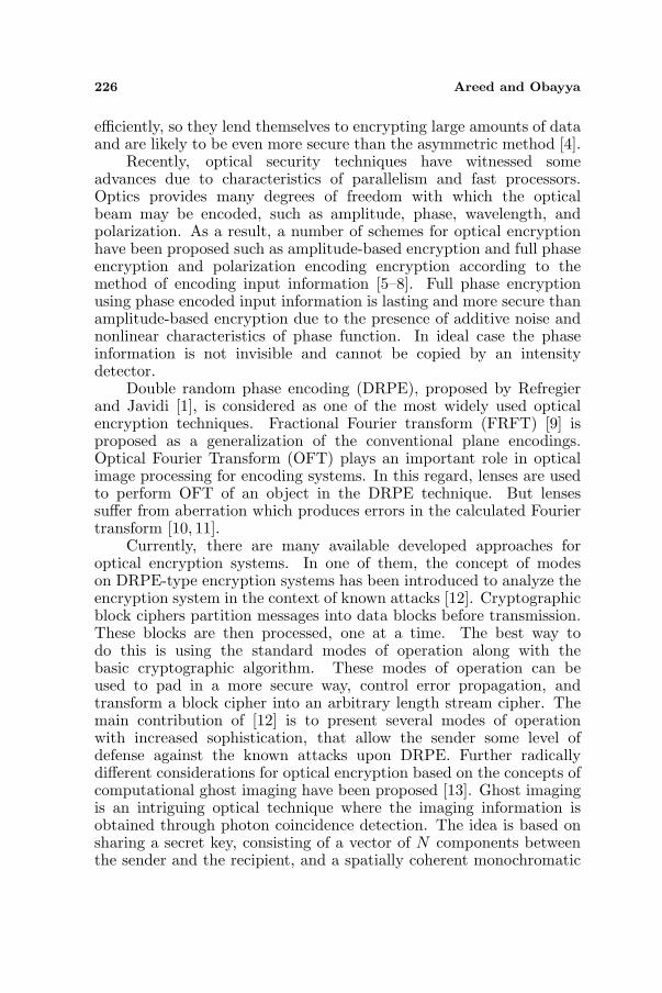
The above analyzed 1D PBG is extended to the 3D PBG case inorder to perform image encryption scheme. Fig. 4 shows the proposedstructure that embodies cubic lattice array of air spherical holes of1mm lattice spacing using dielectric substrate (dielectric constant10.8).
As observed from the analysis of 1D structures, the phase variationis highly sensitive to the orientation of the Bragg-grating plates.However, by employing symmetric 3D PBG structure, the wavesimpinging on the structure will always face the same scatterers, i.e,the phase relationship will remain unchanged and that is the mainadvantage of 3D PBG over the 1D component. The photonic band-gap of different configurations with different spherical hole diametersare tested by calculating the reflection coefficient (S11) as shown inFig. 5. The figure shows that, the hole diameter r = 0.7mm, resultsin a stop band (S11 magnitude near 0 dB and variable S11 phase) over32.532–32.535GHz, whereas the hole diameter r = 0.9 mm, results ina stop band (S11 magnitude near 0 dB and constant S11 phase 127◦)over 32.51–32.55GHz, respectively. The curves prove that, a largebandwidth of the complete band-gap with constant phase is obtainedby large r/A ratio as previously studied.
Next, lattice spacing optimization is applied to increase the S11
phase from 127◦ to 180◦. Fig. 6(b) shows the calculated magnitudeand the phase of the scattering parameter S11 which are nearly 0 dBand 180◦ over 31.1–31.19 GHz, at lattice spacing A = 0.8 mm, and holediameter r = 0.72 mm.
Figure 7 shows the steady state real part of the y-polarizedelectric field along the propagation direction z at the central frequency31.095GHz for the chosen values (0.72 mm, 0.8 mm) for hole diameter

232 Areed and Obayya
Frequency [GHz]
Mag
nit
ude
of
S11
Angle
of
S11 [
Deg
ree]
Magnitude of S11, r/A=0.3
Magnitude of S11, r/A=0.7
Magnitude of S11, r/A=0.9
Phase of S11, r/A=0.3
Phase of S11, r/A=0.7
Phase of S11, r/A=0.9
Magnitude of S11, r/A=0.7
Magnitude of S11, r/A=0.9
Phase of S11, r/A=0.7
Phase of S11, r/A=0.9
2
0
-5
170150130110
32 32.1 32.2 32.3 32.4 32.5 32.6 32.7 32.8 32.9 32.51 32.515 32.52 32.525 32.53 32.535 32.54 32.545 32.55
2
0
-5
Mag
nit
ude
of
S11
170150130110
Angle
of
S11 [
Deg
ree]
33
Frequency [GHz]
(a) (b)
Figure 5. Simulated S11-parameter for different [r/A] ratios, latticespacing, A = 1 mm vs. the frequency bands: (a) 32–33GHz, (b) 32.51–32.55GHz.
(a) (b)
-4 0
-3 0
-2 0
-1 0
0
140160180
..
-40
-30
-20
-10
0
140160180
Mag
nit
ude
of
S11
Angle
of
S11 [
Deg
ree]
Magnitude of S11, r/A=0.7
Magnitude of S11, r/A=0.9
31 31.2 31.4 31.6 31.8 32 32.2 32.4 32.6 32.8 33
Magnitude of S11, r/A=0.7
Magnitude of S11, r/A=0.9
Frequency [GHz]31.1 31.11 31.12 31.13 31.14 31.15 31.16 31.17 31.18 31.19
Angle
of
S11 [
Deg
ree]
Magnitude of S11, r/A=0.9
Phase of S11, r/A=0.9
Frequency [GHz]
Mag
nit
ude
of
S11
Figure 6. Simulated S11-parameter for different [r/A] ratios, A =0.8mm vs. the frequency bands: (a) 31–33 GHz, (b) 31.1–31.2GHz.
and lattice constant, respectively. Computation time for the displayedexample is about 2 hours. It is evident from Fig. 7 that, the reflectedwave along the structure is highly confined and also reaches the steadystate sinusoidal variations at the frequency 31.095GHz which lieswithin the operating bandwidth. This reflected wave confinementclearly agrees with the behavior of S11 shown earlier in Fig. 6(b).
As discussed, the optimum design of our encryptor is at A =0.8mm where we obtain phase of 180◦. However, in an attempt towork out beyond this value of A, we will lose the wave completely dueto the simple fact that it is impossible to catch any reflected waves outof PBG range.
3D PBG technology has become much more mature in therecent years, spanning a number of application areas such as

Progress In Electromagnetics Research C, Vol. 30, 2012 233
-5 0 5 10 15 20 250
2000
4000
6000
8000
10000
12000
14000
16000
Z-axis [mm]
Ab
solu
te o
f E
y
Freq=31.095GHzx
z
(a) (b)
Figure 7. Steady state field profile at F = 31.095GHz versus: (a) xzplane, (b) z-axis.
Proposed 3D PBG
Source image
Encrypted image Demodulat or
Isolator Modulator
Figure 8. Architecture of symmetric key encryption.
telecommunication, sensing, filtering and now, for the first time to ourbest knowledge in encryption as suggested in this paper. The authorsbelieve that the fabrication of 3D PBG is not difficult and has beenalready implemented [27].
4. SIMULATION RESULTS
The main idea behind the proposed method to encrypt digital imagesis to create an easiest and secure hardware key. This paper proposesa new encryption technique which uses the previously designed 3DPBG section as a band-stop filter (zero transmission) with a constantphase of 180◦ over the frequency range of the modulated image.The architecture of the proposed symmetric encryption technique isdepicted in Fig. 8. The encryption technique is realized using thefollowing steps:
Step1: modulate the source image to a central carrier frequency31.14GHz.Step2: the modulated image will be applied to the designed 3D
234 Areed and Obayya
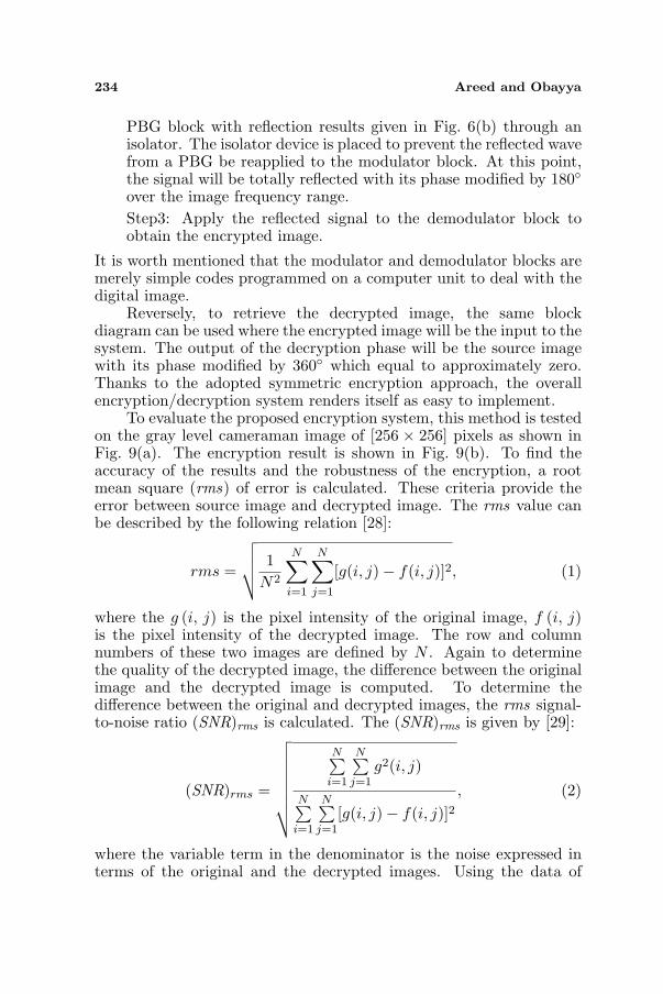
PBG block with reflection results given in Fig. 6(b) through anisolator. The isolator device is placed to prevent the reflected wavefrom a PBG be reapplied to the modulator block. At this point,the signal will be totally reflected with its phase modified by 180◦over the image frequency range.Step3: Apply the reflected signal to the demodulator block toobtain the encrypted image.
It is worth mentioned that the modulator and demodulator blocks aremerely simple codes programmed on a computer unit to deal with thedigital image.
Reversely, to retrieve the decrypted image, the same blockdiagram can be used where the encrypted image will be the input to thesystem. The output of the decryption phase will be the source imagewith its phase modified by 360◦ which equal to approximately zero.Thanks to the adopted symmetric encryption approach, the overallencryption/decryption system renders itself as easy to implement.
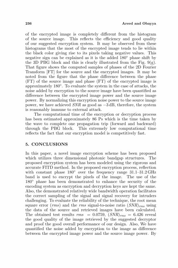
To evaluate the proposed encryption system, this method is testedon the gray level cameraman image of [256 × 256] pixels as shown inFig. 9(a). The encryption result is shown in Fig. 9(b). To find theaccuracy of the results and the robustness of the encryption, a rootmean square (rms) of error is calculated. These criteria provide theerror between source image and decrypted image. The rms value canbe described by the following relation [28]:
rms =
√√√√ 1N2
N∑
i=1
N∑
j=1
[g(i, j)− f(i, j)]2, (1)
where the g (i, j) is the pixel intensity of the original image, f (i, j)is the pixel intensity of the decrypted image. The row and columnnumbers of these two images are defined by N . Again to determinethe quality of the decrypted image, the difference between the originalimage and the decrypted image is computed. To determine thedifference between the original and decrypted images, the rms signal-to-noise ratio (SNR)rms is calculated. The (SNR)rms is given by [29]:
(SNR)rms =
√√√√√√√√
N∑i=1
N∑j=1
g2(i, j)
N∑i=1
N∑j=1
[g(i, j)− f(i, j)]2, (2)
where the variable term in the denominator is the noise expressed interms of the original and the decrypted images. Using the data of

Progress In Electromagnetics Research C, Vol. 30, 2012 235
0
200
400
600
800
1000
0 0.5 1
0
2000
4000
6000
8000
10000
0 0.5 1
0
200
400
600
800
1000
0 0.5 1
(a) (b) (c)
(d) (e)
(g)
0 5 10 15 20-200
-100
0
100
200
First twenty points of the first row of the phase of 2D FT of images
Phase
of
2D
-FT
[D
egre
e]
Source image
Encrypted image
(f)
Figure 9. (a) Source of cameraman image, (b) encrypted image,(c) decrypted image, (d) histogram of the source image, (e) histogramof the encrypted image, (f) histogram of the decrypted image, (g) phasesamples of the 2D FT of the source and encrypted images.
the original image of Fig. 9(a) and the data of retrieved image shownin Fig. 9(c), the values of the rms, and (SNR)rms, are 0.0759, 6.426,respectively. Figs. 9(d), 9(e), and 9(f) show the histograms of thesource, the encrypted and the decrypted images, respectively. Theobtained simulation results of the encryptor design of (SNR)rms andrms clearly agree with the plotted histograms of the source and thedecrypted images where, the histograms are approximately the same.Moreover, it may be noted from the Figs. 9(d), 9(e) that the histogram
236 Areed and Obayya
of the encrypted image is completely different from the histogramof the source image. This reflects the efficiency and good qualityof our suggested encryption system. It may be observed from thesehistograms that the most of the encrypted image tends to lie withinthe black color giving rise to its pixels taking negative values. Thisnegative sign can be explained as it is the added 180◦ phase shift bythe 3D PBG block and this is clearly illustrated from the Fig. 9(g).That figure shows the computed samples of phases of the 2D FourierTransform [FT] for the source and the encrypted images. It may benoted from the figure that the phase difference between the phase(FT) of the source image and phase (FT) of the encrypted image isapproximately 180◦. To evaluate the system in the case of attacks, thenoise added by encryption to the source image have been quantified asdifference between the encrypted image power and the source imagepower. By normalizing this encryption noise power to the source imagepower, we have achieved SNR as good as −3 dB, therefore, the systemis reasonably immune to external attack.
The computational time of the encryption or decryption processhas been estimated approximately 86 Ps which is the time taken bythe wave to complete one propagation trip (forward and backward)through the PBG block. This extremely low computational timereflects the fact that our encryption model is competitively fast.
5. CONCLUSIONS
In this paper, a novel image encryption scheme has been proposedwhich utilizes three dimensional photonic bandgap structures. Theproposed encryption system has been modeled using the rigorous andaccurate FITD method. In the proposed encryption process, reflectionwith constant phase 180◦ over the frequency range 31.1–31.2 GHzband is used to encrypt the pixels of the image. The use of the180◦ phase has been demonstrated to enhance the security of theencoding system as encryption and decryption keys are kept the same.Also, the demonstrated relatively wide bandwidth operation facilitatesthe correct sampling of the signal and signal recovery for intruderschallenging. To evaluate the reliability of the technique, the root meansquare error (rms) and the rms signal-to-noise ratio (SNR)rms usingthe data of the source and retrieved images have been calculated.The obtained test results rms = 0.0759, (SNR)rms = 6.426 revealthe good quality of the image retrieved by the suggested decryptorand proof the good overall performance of our design. Also, We havequantified the noise added by encryption to the image as differencebetween the encrypted image power and the source image power. By

Progress In Electromagnetics Research C, Vol. 30, 2012 237
normalizing this encryption noise power to the source image power,we have achieved SNR as good as −3 dB, therefore, the system isreasonably immune to external attack. Finally, we conclude withthe remark that with the mature fabrication technology of PBGs, theproposed system is a competitive candidate for useful practical imagingsystems covering both microwaves and photonics frequency ranges.
ACKNOWLEDGMENT
The authors would like to acknowledge the Reviewers for the usefulsuggestions to enhance the technical quality of our work.
REFERENCES
1. Refregier, P. and B. Javidi, “Optical image encryption basedon input plane and fourier plane random encoding,” Opt. Lett.,Vol. 20, 767–769, 1995.
2. Chang, H. K. L. and J. L. Liu, “A linear quad tree compressionscheme for image encryption,” Signal Process., Vol. 10, No. 4,279–290, 1997.
3. Holtsnider, B. and B. D. Jaffe, IT Manager’s Handbook: GettingYour New Job Done, 2nd Edition, 373, Morgan Kaufmann, 2006.
4. Qin, W. and X. Peng, “Asymmetric cryptosystem based on phase-truncated fourier transforms,” Opt. Lett., Vol. 35, 118–120, 2010.
5. Monaghan, D. S., U. Gopinathan, T. J. Naughton, andJ. T. Sheridan, “Key-space analysis of double random phaseencryption technique,” App. Opt., Vol. 46, 6641–6647, 2007.
6. Kishk, S. and B. Javidi, “Information hiding technique withdouble phase encoding,” App. Opt., Vol. 41, 5462–5470, 2002.
7. Tao, R., Y. Xin, and Y. Wang, “Double image encryption basedon random phase encoding in the fractional fourier domain,” Opt.Express, Vol. 15, 16067–16077, 2007.
8. Frauel, Y., A. Castro, T. J. Naughton, and B. Javidi, “Resistanceof the double random phase encryption against various attacks,”Opt. Express, Vol. 15, 10253, 2007.
9. Joshi, M., C. shakher, and K. Singh, “Color image encryption anddecryption for twin images in fractional Fourier domain,” Opt.Commun., Vol. 281, 5713–5720, 2008.
10. Castro, J. M., I. B. Djordjevic, and D. F. Geraghty, “Novel superstructure bragg gratings for optical encryption,” J. LightwaveTechnol., Vol. 24, 1875–1885, 2006.
238 Areed and Obayya
11. Singh, M., A. Kumar, and K. Singh, “Encryption and decryptionusing a phase mask set consisting of a random phase maskand sinusoidal phase grating in the fourier plane,” ICOP 2009— International Conference on Optics and Photonics, CSIO,Chandigarh, India, Oct. 30–Nov. 1, 2009.
12. Naughton, T. J., B. M. Hennelly, and T. Dowling, “Introducingsecure modes of operation for optical encryption,” J. Opt. Soc.Am. A, 25, 2608–2617, 2008.
13. Clemente, P., V. Duran, V. Torres-Company, E. Tajahuerce,and J. Lancis, “Optical encryption based on computational ghostimaging,” Opt. Lett., Vol. 35, 2391–2393, 2010.
14. Chen, W. and X. Chen, “Space-based optical image encryption,”Opt. Express, Vol. 18, 27095–27104, 2010.
15. Chen, W., X. Chen, and C. J. R. Sheppard, “Optical double-image cryptography based on diffractive imaging with a laterally-translated phase grating,” Appl. Opt., Vol. 50, 5750–5757, 2011.
16. Perez-Cabre, E., M. Cho, and B. Javidi, “Information authenti-cation using photon-counting double-random-phase encrypted im-ages,” Opt. Lett., Vol. 36, 22–24, 2011.
17. Joannopoulos, J. D., R. D. Meade, and J. N. Winn, PhotonicCrystals: Molding the Flow of Light, Princeton University Press,Princeton, NJ, USA, 1995.
18. D’Orazio, A., M. De Sario, V. Petruzzelli, and F. Prudenzano,“Numerical modeling of photonic band gap waveguiding struc-tures,” Recent Research Developments in Optics, S. G. PandalaiEditor, 2002.
19. Koshiba, M., “Wavelength division multiplexing and demultiplex-ing with photonic crystal waveguide couplers,” J. Lightw. Tech-nol., Vol. 19, No. 12, 1970–1975, 2001.
20. Sharkawy, A., S. Shi, and D. W. Prather, “Multichannelwavelength division multiplexing with photonic crystals,” Appl.Opt., Vol. 40, 2247–2252, 2001.
21. Ozbay, E., M. Bayindir, I. Bulu, and E. Cubukcu, “Investigation oflocalized coupled-cavity modes in twodimensional photonic bandgap structures,” IEEE J. Quantum Electron., Vol. 38, 837–843,2002.
22. Samra, A. S., S. S. Kishk, and S. S. Elnaggar, “A compact lens-lessoptical image encoding system using diffraction grating,” IJCSNSInternational Journal of Computer Science and Network Security,Vol. 10, No. 6, Jun. 2010.
23. Weiland, T., et al., “Verfahren und anwendungen der feldsimula-

Progress In Electromagnetics Research C, Vol. 30, 2012 239
tion,” Darmstadt, 2002.24. Krietenstein, B., R. Schuhmann, P. Thoma, and T. Weiland, “The
perfect boundary approximation technique facing the challengeof high precision field computation,” Proceedings of the XIXInternational Linear Accelerator Conference (LINAC’98), 860–862, Chicago, USA, 1998.
25. Weiland, T., “Time domain electromagnetic field computationwith finite difference methods,” International Journal of Numer-ical Modelling, Vol. 9, 295–319, 1996.
26. Canning, J., “Fiber gratings and devices for sensors and lasers,”Lasers Photonics Rev., Vol. 2, No. 4, 275–289, Wiley, USA, 2008.
27. Prather, D. W., A. Sharkawy, S. Shi, J. Murakowski, andG. Schneider, Photonic Crystals, Theory, Applications andFabrication, Wiley, Jun. 2009.
28. Servin, M., D. Malacara, and R. Rodriguez-Vera, Appl. Opt.,Vol. 33, 2589–2595, 1994.
29. Gonzalez, R. C. and P. Wints, Digital Image Processing, 2ndEdition, Addison Wesley Publishing Company, USA, 1987.