novel electrotextile patch antenna on jeans substrate for
TRANSCRIPT

Progress In Electromagnetics Research C, Vol. 83, 255–265, 2018
Novel Electrotextile Patch Antenna on Jeans Substratefor Wearable Applications
Mohamed I. Ahmed1, *, Mai F. Ahmed2, and Abd-El A. Shaalan2
Abstract—This paper aimed to take closer steps towards real wearability by investigating thepossibilities of designing and fabricating highly efficient and fully flexible wearable microstrip patchantenna for operating frequency of 5.8 GHz as a center frequency. Two types of conducting materialshave been used for conducting parts: conventional metal plane and woven electro-textile material, whilea non-conducting jeans fabric has been used as antenna substrate material. The dielectric constantεr = 1.78, and loss tangent tan δ = 0.085 of the jeans substrate measured by using two different methods.Also, the electromagnetic properties of the electro-textile are studied in details. The conductivity of e-textile cell is equal to 2.5×10⁶ S/m and the surface impedance of e-textile cell equal to 0.0395+J18.4Ω.Furthermore, the proposed wearable antenna may be attached to human body, so the specific absorptionratio (SAR) must be calculated. Finally, the proposed design is simulated by CST simulator version2016, fabricated using folded copper and measured by Agilent8719ES VNA.
1. INTRODUCTION
Wearable, body-worn antennas get more and more attention for body-centric communications becausethey can be easily worn on body and integrated into clothes [1]. Since 1997, wearable systems havebecome common subjects in researches. Many papers have been published about the design, fabricationand applications of these antennas. Some of these developments are reported in [2–4]. In recent years,electro-textiles (e-textiles) have taken a lot of attention as hopeful materials for the development ofwearable antennas to make them fully flexible, which allows the smart clothes to communicate freelythrough wireless networks [5]. E-textiles are used as antenna patches and ground plane, while dielectric-textiles are used as antenna substrates [6–9].
In the antenna design, as the dielectric properties of the textile substrate, dielectric constant andloss tangent play important roles in the propagation of electromagnetic energy in dielectric media andhave effect on the antenna performance [10]. The electromagnetic properties of the electro-textiles alsoplay vital roles in antenna design and performance [11].
This paper includes an e-textile patch antenna design which is made from Jeans fabric substratematerial with two types of conducting materials that will be discussed in more details in the followingsections. Two different methods for fabric characterization are presented. The first method is amicrostrip ring resonator. The second is DAC equipment (Dielectric Assessment Kit) setup to confirmthe results. Further, this paper studies the electromagnetic properties of e-textiles for wearable antennasand calculates the basic resistance and inductance in a grid. Also, the SAR calculations for the presentedantennas are performed on-body environments to ensure they operate properly in the nearness of thehuman body.
Received 3 March 2018, Accepted 12 April 2018, Scheduled 30 April 2018* Corresponding author: Mohamed Ismail Ahmed ([email protected]).1 Microstrip Department, Electronics Research Institute, Giza, Egypt. 2 Department of Electrical & Electronics Engineering, Facultyof Engineering, Zagazig University, Zagazig, Egypt.

256 Ahmed, Ahmed, and Shaalan
2. MEASUREMENT OF JEANS TEXTILE CHARACTERISTICS
The dielectric constant and loss tangent for jeans textile material are measured by using two differentmethods. The first is a microstrip ring resonator method. The ring resonator model consists of a ringand two feed lines pasted on the upper surface of the jeans substrate. The ground plane occupies thelower surface of the jeans substrate, and a small gap Δ is also included between the ring and each feedline [12, 13]. The fabricated ring resonator model is shown in Fig. 1(a). By measuring S21 for this modelshown in Fig. 1(b), the dielectric constant and loss tangent for jeans textile material can be measured.The peak in S21 was recorded around each resonance. The nth resonance occurs at [13]:
fn =nc
2πr√
εr(1)
where r is the mean radius, c the speed of light in a vacuum, and εr the required relative dielectricconstant.
(a)
(b)
Figure 1. The fabricated ring resonator model pasted on jeans substrate: (a) fabricated geometry, and(b) measured S21 with the frequency.
The insertion loss (S21 (dB)) is introduced as [13],
IL = 20 log10
(1−QL
Qu
)(2)
where QL and Qu are the loaded and unloaded quality factors.From the loaded and unloaded quality factors the loss tangent can be obtained and more details
in [14]. The results of ring resonator method for characterization of jeans textile are mentioned inTable 1.
Table 1. The results of ring resonator method for characterization of jeans textile substrate.
Material ModeResonance
Frequency (GHz)S21
(dB)dielectric
constant (εr)loss tangent
(tan δ)
Jeansn = 1 4.26 −35.5 1.73 0.077n = 2 8.89 −36.9 1.69 0.073

Progress In Electromagnetics Research C, Vol. 83, 2018 257
The second method is DAC (Dielectric Assessment Kit) equipment [15]. Therefore, it has beenused to confirm the results determined using the first one. Comparing the obtained results using thetwo methods, it can be observed that close values are found between the two methods for jeans textilematerial and more details in [14]. The measured dielectric constant, loss tangent and thickness of thejeans substrate are mentioned in Table 2.
Table 2. The charactrization results of the jeans textile substrate.
Substrate Material Dielectric constant (εr) loss tangent (tan δ) Thickness (mm)Jeans 1.78 0.085 0.6
Comparing the obtained results of the two methods, it can be observed that close values are foundbetween the two methods for jeans textile material, but there are some slight differences between them,which is an inherent thing.
3. ELECTROMAGNETIC PROPERTIES OF E-TEXTILE CELL
Generally, there are two methods to make the dielectric textile electrically conductive. The first one is byapplying conductive coating on the dielectric textile surface. The second is by interleaving normal fabricswith conductive metal threads via weaving or knitting [16]. However, woven fabrics perform better thancoated fabrics, because of discontinuities of coated fabrics which increase the surface resistance [17]. Wecan also increase the conductivity of woven fabrics by increasing the conductive thread density in it.
Woven electro-textile fabric has more intersections in its pattern, which means that less distancebetween metal grids aligned along the current flow to keep conduction losses as low as possible as shownin Fig. 2 [18].
(a) (b)
Figure 2. Woven pattern of fabric: (a) front, (b) back [18].
In this paper, the e-textile has a woven pattern with woven density N ppi, and the conductivefabrics are made from round copper wires, with diameter of 80 µm.
The distance between two conductive wires in any woven fabrics can be expressed as [18],
d =25.4 − 0.08N
N − 1(mm) (3)
If the distance between two conductive wires (d) is equal to 0.5 mm in this paper, the copper densityin this fabric is 45 ppi.
Although connective threads are not normally considered components, they have very importantproperties of noise and high frequency performance of electronic circuits [19]. So, for the conductivethreads whose length is a small fraction of the wavelength, the two most important characteristics areresistance and inductance [19]. In this paper, the proposed wearable antenna is used in the WiFi band,especially at 5.8 GHz. Furthermore, the wavelength can be calculated by:
λ = c/f0 (4)

258 Ahmed, Ahmed, and Shaalan
where c is the speed of light, and f is the resonance frequency.While f0 = 5.8 GHz, the wavelength is equal to 51.7 mm. In addition, the electrical dimensions
of the e-textile cells are electrical small approximately equal to λ/10, so we should construct lumpedparameter electric circuit models. In many cases, the inductance is more important than resistance.Even at relatively low frequencies, a conductive thread usually has more inductive reactance thanresistance [19].
3.1. Inductance of Round Conductive Threads
The total inductance is actually the sum of the internal inductance plus external inductance. Theinternal inductance is the effect of the magnetic field within the conductive wire itself, and it is usuallynegligible compared with the external inductance except for closely spaced conductive wires [19]. Inaddition, internal inductance is reduced even more when high-frequency currents are considered becauseas the result of skin effect, the current is concentrated near the surface of the conductor [19]. In thispaper, the skin depth of the copper wires at resonance frequency can be calculated by [19],
δs =1√
πf0μ0σ(5)
where f0 is the resonance frequency, μ0 the permeability of free space, π a constant approximately equalto 3.14159, and σc the conductivity of copper wire (σc = 5.8 × 10⁷ s/m).
While at f0 = 5.8 GHz, the skin depth is equal to 8.68× 10⁻⁷, which is a little distance. Therefore,the external inductance is normally the only inductance of significance where the radius of the copperwire rc > 2δs. In this paper, we assume that the two wires are separated (d/rc > 5) (d is the distancebetween the two wires). According to this condition, the per unit-length of the external inductance oftwo parallel wires can be expressed as [20],
l =μ0
πln
d
rc(6)
where rc is the copper wire radius, μ the permeability of the free space (μ = 4π× 10−7 H/m), and d thedistance between two wires.
From Eq. (6), we can get that the per-unit-length inductance is 1.01 × 10⁻⁶ H/m, and then theinductance in a grid length is L = 0.505 nH.
3.2. Resistance of Round Conductive Threads
Resistance is the second important characteristic of a round conductive copper wire. At high frequency,due to the skin effect, the resistance of conductive wires is a surface resistance where all the currentsare surface currents [19]. In this paper, the ratio between the radius of the copper wire and skin depthis rc/δs ∼ 46. So, the per-unit-length of the surface resistance of copper wire can be expressed as [20];
r =1
2rc
√μ0f0
πσcrc � δs (7)
where rc is the copper wire radius, μ the permeability of the free space (μ = 4π × 10−7 H/m), f theoperating frequency, σc the copper conductivity (σc = 5.8 × 10⁷ S/m), and d the distance between twowire.
From Eq. (7), we can get that the per-unit-length resistance of copper wire is 79.06 Ω/m, and thenthe resistance in a grid length is R = 0.0395Ω.
3.3. The Conductivity and Surface Impedance of E-Textile Cell
Now, we can calculate the conductivity of e-textile cell where the conductivity (σ) is the reciprocal ofthe resistivity (ρ). The resistivity of an e-textile cell can be calculated by [21],
ρ = r × A = r × πd2c
4(8)
Progress In Electromagnetics Research C, Vol. 83, 2018 259
where r is the per-unit-length resistance of copper wire; A is the cross section area over which thecurrent flows; dc is the diameter of the copper wire.
From Eq. (9), we can get that the resistivity is equal to 3.9× 10⁻⁷ Ω ·m and then the conductivityof e-textile cell equal to σ = 1ρ = 2.5×10⁶ S/m). Although electro-textile material has less conductivitythan pure copper material (σ < σc), this material achieves real wearability for the body-worn microstripantenna Furthermore, the surface impedance of e-textile cell can be calculated by [21],
Z = R + JXL = R + J2πf0L (9)
where R is the resistance in a grid length, π a constant approximately equal to 3.14159, f the operatingfrequency, and L the inductance in a grid length.
From Eq. (9), we can get the surface impedance as Z = 0.0395+J18.4Ω. Furthermore, the copperwire has very low resistance value, so the antenna with e-textile material is efficient and more flexible.
4. ANTENNA DESIGN
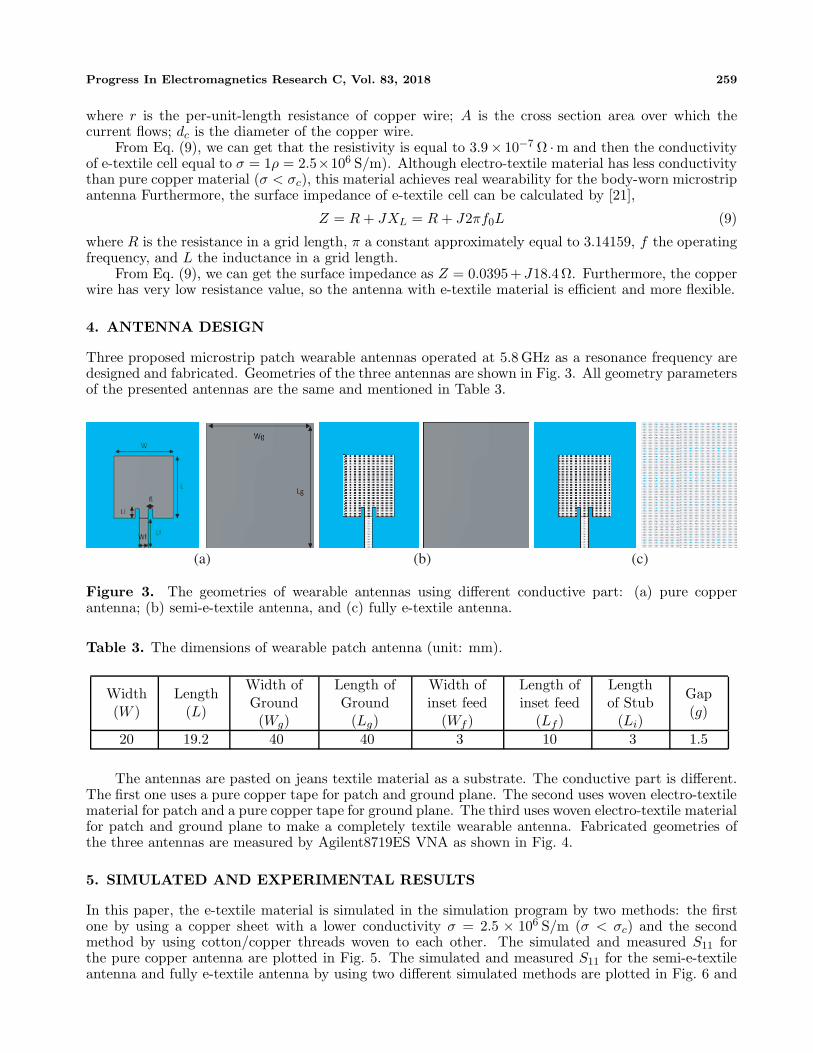
Three proposed microstrip patch wearable antennas operated at 5.8 GHz as a resonance frequency aredesigned and fabricated. Geometries of the three antennas are shown in Fig. 3. All geometry parametersof the presented antennas are the same and mentioned in Table 3.
(a) (b) (c)
Figure 3. The geometries of wearable antennas using different conductive part: (a) pure copperantenna; (b) semi-e-textile antenna, and (c) fully e-textile antenna.
Table 3. The dimensions of wearable patch antenna (unit: mm).
Width(W )
Length(L)
Width ofGround(Wg)
Length ofGround
(Lg)
Width ofinset feed
(Wf )
Length ofinset feed
(Lf )
Lengthof Stub
(Li)
Gap(g)
20 19.2 40 40 3 10 3 1.5
The antennas are pasted on jeans textile material as a substrate. The conductive part is different.The first one uses a pure copper tape for patch and ground plane. The second uses woven electro-textilematerial for patch and a pure copper tape for ground plane. The third uses woven electro-textile materialfor patch and ground plane to make a completely textile wearable antenna. Fabricated geometries ofthe three antennas are measured by Agilent8719ES VNA as shown in Fig. 4.
5. SIMULATED AND EXPERIMENTAL RESULTS
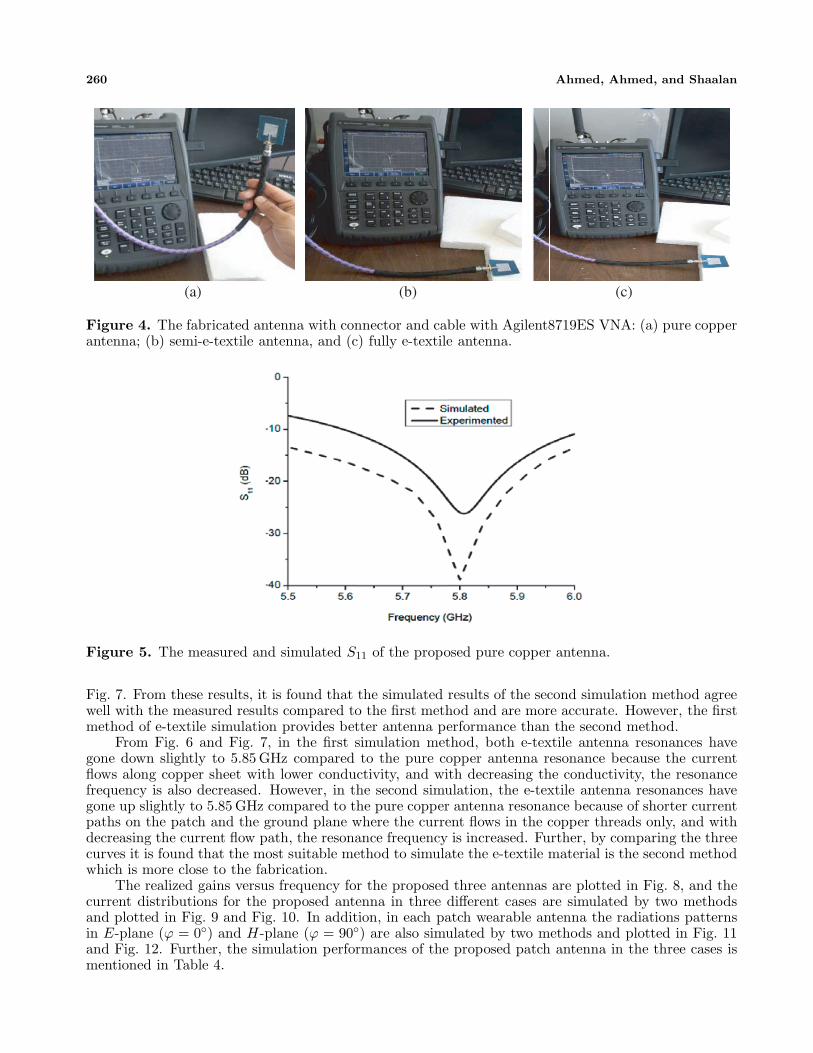
In this paper, the e-textile material is simulated in the simulation program by two methods: the firstone by using a copper sheet with a lower conductivity σ = 2.5 × 10⁶ S/m (σ < σc) and the secondmethod by using cotton/copper threads woven to each other. The simulated and measured S11 forthe pure copper antenna are plotted in Fig. 5. The simulated and measured S11 for the semi-e-textileantenna and fully e-textile antenna by using two different simulated methods are plotted in Fig. 6 and
260 Ahmed, Ahmed, and Shaalan
(a) (b) (c)
Figure 4. The fabricated antenna with connector and cable with Agilent8719ES VNA: (a) pure copperantenna; (b) semi-e-textile antenna, and (c) fully e-textile antenna.
Figure 5. The measured and simulated S11 of the proposed pure copper antenna.
Fig. 7. From these results, it is found that the simulated results of the second simulation method agreewell with the measured results compared to the first method and are more accurate. However, the firstmethod of e-textile simulation provides better antenna performance than the second method.
From Fig. 6 and Fig. 7, in the first simulation method, both e-textile antenna resonances havegone down slightly to 5.85 GHz compared to the pure copper antenna resonance because the currentflows along copper sheet with lower conductivity, and with decreasing the conductivity, the resonancefrequency is also decreased. However, in the second simulation, the e-textile antenna resonances havegone up slightly to 5.85 GHz compared to the pure copper antenna resonance because of shorter currentpaths on the patch and the ground plane where the current flows in the copper threads only, and withdecreasing the current flow path, the resonance frequency is increased. Further, by comparing the threecurves it is found that the most suitable method to simulate the e-textile material is the second methodwhich is more close to the fabrication.
The realized gains versus frequency for the proposed three antennas are plotted in Fig. 8, and thecurrent distributions for the proposed antenna in three different cases are simulated by two methodsand plotted in Fig. 9 and Fig. 10. In addition, in each patch wearable antenna the radiations patternsin E-plane (ϕ = 0◦) and H-plane (ϕ = 90◦) are also simulated by two methods and plotted in Fig. 11and Fig. 12. Further, the simulation performances of the proposed patch antenna in the three cases ismentioned in Table 4.

Progress In Electromagnetics Research C, Vol. 83, 2018 261
Figure 6. The measured and simulated S11 of the proposed semi-electro-textile antenna.
Figure 7. The measured and simulated S11 of the proposed fully-electro-textile antenna.
From Fig. 8 and Table 4, the pure copper tape antenna and semi-e-textile antenna have closevalues in the gain and efficiency and are better than the fully e-textile antenna. However, the coppertape is not reliable; it may be flaked off and breaks. Also, the e-textile antenna has some drawbacks.For example, there is an obvious offset in the frequency band as well as decreased radiation efficiency.So, the fully e-textile antenna is an efficient and fully flexible wearable microstrip patch antenna withacceptable performance.
Finally, SAR simulation results according to the international safety standards [22] FCC (SAR <1.6 mW/kg over 1 g) and ICNIPR (SAR < 2 mW/kg over 10 g) for the proposed antenna in differentcases are shown in Fig. 13, and these results are mentioned in Table 5. These results are carried outon CST MICROWAVE STUDIO 2016 simulator. It is a full wave numerical simulator which uses thefinite integration technique (FIT) [23].

262 Ahmed, Ahmed, and Shaalan
Figure 8. The realized gains for the proposed antenna in different cases and by two simulation method.
(a) (b) (c)
Figure 9. The current distribution of different proposed antenna using copper sheet with σ < σc: (a)pure copper antenna; (b) semi-e-textile antenna, and (c) fully e-textile antenna.
Table 4. The simulation performance of the proposed patch antenna in the three cases.
Antenna
Type
Using copper sheet with σ < σc Using cotton/copper threads
Resonant
Freq.
(GHz)
Return
Loss
S11
(dB)
Gain
(dB)
Efficiency
(%)
Resonant
Freq.
(GHz)
Return
Loss
S11
(dB)
Gain
(dB)
Efficiency
(%)
Pure
copper5.8085 −38.53 6.68 65 5.8085 −38.53 6.68 65
Semi-
e-textile5.7971 −31.277 6.57 62 5.86 −37.843 4.52 59.8
Fully
e-textile5.7092 −28.824 6.49 59 5.892 −21.52 3.05 54.1
From Table 5, it is found that all SAR values are very low and satisfy the international safetystandards. However, by using e-textile material instead of copper tape in the antenna design, the SARvalue is increased a little due to increasing the back radiation, but still an acceptable value.

Progress In Electromagnetics Research C, Vol. 83, 2018 263
(a) (b) (c)
Figure 10. The current distribution of different proposed antenna using cotton/copper threads: (a)pure copper antenna; (b) semi-e-textile antenna, and (c) fully e-textile antenna.
(a) (b)
Figure 11. Radiation pattern for the three antennas at 5.8 GHz in: (a) E-plane (ϕ = 0◦) and (b)H-plane (ϕ = 90◦) using copper sheet with σ < σc.
(a) (b)
Figure 12. Radiation pattern for the three antennas at 5.8 GHz in: (a) E-plane (ϕ = 0◦) and (b)H-plane (ϕ = 90◦) cotton/copper threads.

264 Ahmed, Ahmed, and Shaalan
(a) (b) (c)
Figure 13. SAR distribution on human voxel model (10 g) in distance 10 mm from antenna at 5.8 GHz:(a) pure copper antenna; (b) semi-e-textile antenna, and (c) fully e-textile antenna.
Table 5. The peak SAR values for the proposed antenna in three different cases in distance 10 mmfrom antenna at 5.8 GHz by FCC (1 g) & ICNIPR (10 g) standards.
Antenna TypeSAR value (w/kg)
10 g 1 gPure copper 0.00339 0.00866Semi-e-textile 0.00366 0.00933Fully e-textile 0.00436 0.0111
6. CONCLUSION
This paper presents the design and fabrication of an efficient and fully flexible e-textile wearablemicrostrip patch antenna pasted on jeans textile material to operate at 5.8 GHz as a center frequency,aimed to achieve real wearability in the wearable antenna design. The dielectric properties εr = 1.78 ofthe jeans substrate are measured by using two different methods: a microstrip ring resonator method andDAC (Dielectric Assessment Kit) equipment. The electromagnetic properties of e-textiles for wearableantennas like conductivity and surface impedance are studied. The basic resistance and inductance ina grid are calculated. Two methods are used for simulating the e-textile material in the simulationprogram. Although the first method obtains better performance results than the second, the secondmethod is more close to the fabricated antenna. Further, the SAR value is considered an importantparameter. In our design, the SAR value is very low and increased slightly by using e-textile material.All antennas are measured by Agilent 8719ES VNA. The measured results agree well with those obtainedby the simulator from CST.
ACKNOWLEDGMENT
The authors acknowledge the Fabrics Department in National Research Center support generouslyresearch facilities.
REFERENCES
1. Jiang, Z. H., M. D. Gregory, and D. H. Werner, “Design and experimental investigation of acompact circularly polarized integrated filtering antenna for wearable biotelemetric devices,” IEEETransactions on Biomedical Circuits and Systems, Vol. 10, No. 2, 328–338, Apr. 2016.

Progress In Electromagnetics Research C, Vol. 83, 2018 265
2. Langenhove, L. V., Smart Textiles for Medicine and Healthcare, CRC Press, Cambridge, England,2007.
3. Park, S. and S. Jayaraman, “Wearable biomedical systems: Research to reality,” IEEE InternationalConference on Portable Information Devices, May 2007.
4. Sankaralingam, S. and B. Gupta, “Development of textile antennas for body wearable applicationsand investigations on their performance under bent conditions,” Progress In ElectromagneticsResearch B, Vol. 22, 53–71, 2010.
5. Kennedy, T. F., P. W. Fink, A. W. Chu, N. J. Champagne, G. Y. Lin, and M. A. Khayat, “Body-worn e-textile antennas: The good, the low mass, and the conformal,” IEEE Transactions onAntennas and Propagation, Vol. 57, 910–918, 2009.
6. Ouyang, Y., E. Karayianni, and W. J. Chappell, “Effect of fabric patterns on electro-textile patchantennas,” IEEE Antennas and Propagation Society International Symposium, Vol. 2B, 246–249,2005.
7. Abbasi, M. A. B., S. S. Nikolaou, M. A. Antoniades, M. N. Stevanovic, and P. Vryonides, “CompactEBG-backed planar monopole for BAN wearable applications,” IEEE Transactions on Antennasand Propagation, Vol. 65, No. 2, 453–463, Feb. 2017.
8. Lotfi, P., S. Soltani, and R. D. Murch, “Printed endfire beam-steerable pixel antenna,” IEEETransactions on Antennas and Propagation, Vol. 65, No. 8, 3913–3923, Aug. 2017.
9. Zhong, J., A. Kiourti, T. Sebastian, Y. Bayram, and J. L. Volakis, “Conformal load-bearing spiralantenna on conductive textile threads,” IEEE Antennas and Wireless Propagation Letters, Vol. 16,230–233, 2017.
10. Kiourti, A., C. Lee, and J. L. Volakis, “Fabrication of textile antennas and circuits with 0.1 mmprecision,” IEEE Antennas and Wireless Propagation Letters, Vol. 15, 151–153, 2015.
11. Ouyang, Y. and W. J. Chappell, “High frequency properties of electro-textiles for wearable antennaapplications,” IEEE Transactions on Antennas and Propagation, Vol. 56, No. 2, Feb. 2008.
12. Hopkins, R. and C. Free, “Equivalent circuit for the microstrip ring resonator suitable for broadbandmaterials characterization,” IET Microwaves, Antennas & Propagation, Vol. 2, No. 1 , 66–73, Feb.2008.
13. Pozar, D. M., “Electromagnetic theory,” Microwave Engineering, 3rd Edition, John Wiley andSons, Inc., Hoboken, NJ, 2005.
14. Ahmed, M. I., M. F. Ahmed, and A. A. Shaalan, “Investigation and comparison of 2.4 GHz wearableantennas on three textile substrates and its performance characteristics,” Open Journal of Antennasand Propagation, Vol. 5, 110–120, 2017.
15. https://www.speag.com/products/dak/dielectric-measurements/.16. Quirk, M. M., T. L. Martin, and M. T. Jones, “Inclusion of fabric properties in the e-textile design
process,” Proceedings of International Symposium on Wearable Computers, 37–40, 2009.17. Locher, I., M. Klemm, T. Kirstein, and G. Troster, “Design and characterization of purely textile
patch antennas,” IEEE Trans. Adv. Pack., Vol. 29, 777–788, 2006.18. Ouyang, Y. and W. J. Chappell, “High frequency properties of electrotextiles for wearable antenna
applications,” IEEE Transactions on Antennas and Propagation, Vol. 56, No. 2, 381–389, 2008.19. Paul, C. R., Introduction to Electromagnetic Compatibility, 2nd Edition, Wiley, New York, 2006.20. Quirk, M. M., T. L. Martin, and M. T. Jones, “Inclusion of fabric properties in the e-textile design
process,” Proceedings of International Symposium on Wearable Computers, 37–40, 2009.21. Balanis, C. A., Antenna Theory: Analysis and Design, 2nd Edition, Wiley, New York, 1996.22. IEEE C95.1-2005, “IEEE standards for safety levels with respect to human exposure to radio
frequency electromagnetic fields, 3 kHz to 300 kHz,” Institute of Electrical and ElectronicsEngineers, New York, NY, 2005.
23. CST MICROWAVE STUDIO R©, help, http://www.cst.com.