novel range-doppler processing and waveform design method ... · there are various disadvantages in...
TRANSCRIPT

Novel range-Doppler processing and waveform design method for extending unambiguous Doppler
Yinsheng Wei*,Zhineng Mao Department of Electronic Engineering
Harbin Institute of Technology Harbin, China
*E-mail: [email protected]
Abstract—Coherent pulse train can obtain high Doppler resolution, but leads to range and Doppler ambiguity. Thus, the staggered pulse repetition frequencies (PRFs) is proposed to extend the unambiguous range or Doppler coverage. However, there are various disadvantages in pulse-to-pulse stagger or block-to-block stagger. In this paper, inspired by the Doppler compensation processing, we propose a modified range-Doppler (RD) processing method. Moreover, a waveform design scheme matching this method is also presented. The modified RD processing associated with the designed waveform can effectively extend the unambiguous Doppler coverage without affecting the unambiguous range. Experimental evidence verified the effectiveness of the modified RD processing method and the designed waveform.
Keywords—Doppler ambiguity; modified range-Doppler processing; waveform design; recurrent Doppler sidelobes suppression
I. INTRODUCTION In many cases of practical interest, coherent pulse train is
transmitted to improve the Doppler resolution, but leads to Doppler and delay ambiguities. The unambiguous Doppler coverage is the reciprocal of the pulse repetition interval (PRI) and the unambiguous delay coverage is equal to the PRI, i.e. the unambiguous delay-Doppler product (DDP) is unit one. However, the delay-Doppler coupling can result in the situation that no PRF can allow unambiguous coverage of both the delay and Doppler of interest. In order to solve this problem, reference [1,2] present the staggered PRFs. Staggered PRFs can be performed on the pulse-to-pulse or block-to-block basis. The PRI between every two pulses in the coherent accumulation time is different in pulse-to-pulse staggered PRFs signal. One disadvantage is that the slow-time data sequence in a given range are non-uniformly sampled, which makes Doppler processing more difficult. Another is that range-ambiguous mainlobe clutter can cause large pulse-to-pulse amplitude variation as the PRF varies[3]. As for the block-to-block staggered system, the major disadvantage is that the use of multiple CPIs consumes large amounts of the radar timeline. Besides, the target may straddle bins and the noise may cause a large error in the estimated value[3]. Furthermore, if the number of targets is greater than or equal to the number of PRFs, ghosts will appear[4].
In this paper, inspired by the Doppler compensation[5~7] processing of Doppler sensitive signals, we present a modified range-Doppler (RD) processing method and a corresponding waveform design scheme to deal with the RD coupling. The modified RD processing method extends the unambiguous Doppler coverage by adding additional compensating channels. But the modified RD processing will fail when transmitting the conventional frequency modulation continuous waveform (FMCW). As for the Doppler sensitive signal, such as phase-coded waveform or frequency-coded waveform, the Doppler ambiguity can been resolved. However, high recurrent Doppler sidelobes will result in serious interference between channels. Thus, a waveform design scheme is also proposed which focus on the recurrent Doppler sidelobes suppression.
The rest of the paper is organized as follows. In Section II, we present the conventional RD processing and the Doppler compensation scheme. Then the modified RD processing is proposed together with the waveform design method. In Section III, simulation results are reported to verify the effectiveness of the modified RD processing and the designed waveform. Section IV concludes this paper.
II. PROBLEM FORMULATION AND WAVEFORM DESIGN
A. Conventional Signal processing Considering a baseband signal u(t) with duration T, the
ambiguity function (AF) can be written as:
* 2
0
* 2 ( )
0*
2 2 *
0
*2 2 *
( , ) ( ) ( )
( ) ( )
( ) ( )
( ) ( )
T j t
T j t
Tj j t
j j
u t u t e dt
u t u t e dt
e u t e u t dt
e u e u
πξ
πξ τ
πξτ πξ
πξτ πξτ
χ τ ξ τ
τ
τ
τ τ
−
− −
− −
= +
= −
= −
= ⊗ −
(1)
Generally, the radar transmits periodic pulses for the consideration of the Doppler resolution. In this paper, we focus on continuous wave, i.e. the PRI is equal to signal duration T. Then, the symbol ⊗ stands for periodic convolution, the AF turns into periodic AF[8]. We assume that the transmitted waveform is:
( ) ( )n
s t u t nT= − (2)
Then, the return of a target with delay τ and Doppler frequency ξ can be simplified as:
2
2
2 2 ( )
ˆ22
( ) (( )
( )
ˆ( ) n
j tr
j t
nj nT j t nT
n
j tj nTn
n
s t s t ee u t nT
e u t nT e
e u t e
πξ
πξ
πξ πξ
πξπξ
σ τσ τ
σ τ
σ τ
−
= − )
= − −
= − −
= −
(3)
where σ denotes the backscattering coefficient of the target, and n̂t is the fast time of the nth cycle.
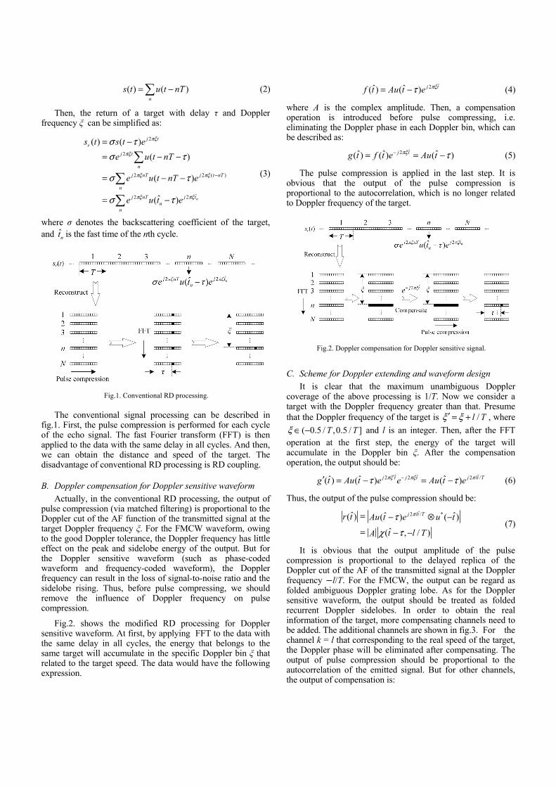
The conventional signal processing can be described in
fig.1. First, the pulse compression is performed for each cycle of the echo signal. The fast Fourier transform (FFT) is then applied to the data with the same delay in all cycles. And then, we can obtain the distance and speed of the target. The disadvantage of conventional RD processing is RD coupling.
B. Doppler compensation for Doppler sensitive waveform Actually, in the conventional RD processing, the output of
pulse compression (via matched filtering) is proportional to the Doppler cut of the AF function of the transmitted signal at the target Doppler frequency ξ. For the FMCW waveform, owing to the good Doppler tolerance, the Doppler frequency has little effect on the peak and sidelobe energy of the output. But for the Doppler sensitive waveform (such as phase-coded waveform and frequency-coded waveform), the Doppler frequency can result in the loss of signal-to-noise ratio and the sidelobe rising. Thus, before pulse compressing, we should remove the influence of Doppler frequency on pulse compression.
Fig.2. shows the modified RD processing for Doppler sensitive waveform. At first, by applying FFT to the data with the same delay in all cycles, the energy that belongs to the same target will accumulate in the specific Doppler bin ξ that related to the target speed. The data would have the following expression.
ˆ2ˆ ˆ( ) ( ) j tf t Au t e πξτ= − (4)
where A is the complex amplitude. Then, a compensation operation is introduced before pulse compressing, i.e. eliminating the Doppler phase in each Doppler bin, which can be described as:
ˆ2ˆ ˆ ˆ( ) ( ) ( )j tg t f t e Au tπξ τ−= = − (5)
The pulse compression is applied in the last step. It is obvious that the output of the pulse compression is proportional to the autocorrelation, which is no longer related to Doppler frequency of the target.
C. Scheme for Doppler extending and waveform design It is clear that the maximum unambiguous Doppler
coverage of the above processing is 1/T. Now we consider a target with the Doppler frequency greater than that. Presume that the Doppler frequency of the target is /l Tξ ξ′ = + , where
( 0.5 / ,0.5 / ]T Tξ ∈ − and l is an integer. Then, after the FFT operation at the first step, the energy of the target will accumulate in the Doppler bin ξ. After the compensation operation, the output should be:
ˆ ˆ ˆ2 2 2 /ˆ ˆ ˆ( ) ( ) ( )j t j t j lt Tg t Au t e e Au t eπξ πξ πτ τ′ −′ = − = − (6)
Thus, the output of the pulse compression should be:
ˆ2 / *ˆ ˆ ˆ( ) ( ) ( )
ˆ( , / )
j lt Tr t Au t e u t
t l TA
πτ
χ τ
= − ⊗ −
= − − (7)
It is obvious that the output amplitude of the pulse compression is proportional to the delayed replica of the Doppler cut of the AF of the transmitted signal at the Doppler frequency −l/T. For the FMCW, the output can be regard as folded ambiguous Doppler grating lobe. As for the Doppler sensitive waveform, the output should be treated as folded recurrent Doppler sidelobes. In order to obtain the real information of the target, more compensating channels need to be added. The additional channels are shown in fig.3. For the channel k = l that corresponding to the real speed of the target, the Doppler phase will be eliminated after compensating. The output of pulse compression should be proportional to the autocorrelation of the emitted signal. But for other channels, the output of compensation is:
Fig.2. Doppler compensation for Doppler sensitive signal.
Fig.1. Conventional RD processing.
ˆ ˆ ˆ2 2 ( / ) 2 ( ) /ˆ ˆ ˆ( ) ( ) ( )j t j k T t j l k t Tg t Au t e e Au t eπξ π ξ πτ τ′ − + −′′ = − = − (8)
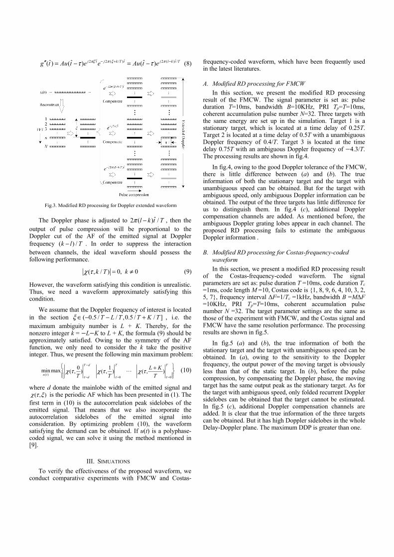
The Doppler phase is adjusted to ˆ2 ( ) /l k t Tπ − , then the
output of pulse compression will be proportional to the Doppler cut of the AF of the emitted signal at Doppler frequency ( ) /k l T− . In order to suppress the interaction between channels, the ideal waveform should possess the following performance.
0, 0( , / ) kk Tχ τ = ≠ (9)
However, the waveform satisfying this condition is unrealistic. Thus, we need a waveform approximately satisfying this condition.
We assume that the Doppler frequency of interest is located in the section ( 0.5 / / ,0.5 / / ]T L T T K Tξ ∈ − − + , i.e. the maximum ambiguity number is L + K. Thereby, for the nonzero integer k = −L−K to L + K, the formula (9) should be approximately satisfied. Owing to the symmetry of the AF function, we only need to consider the k take the positive integer. Thus, we present the following min maximum problem:
( )= =0 =0
0 1min max ( , ) ( , ) ( , )T d T T
u td
L KT T Tτ τ τ
χ τ χ τ χ τ− +
(10)
where d donate the mainlobe width of the emitted signal and ( , )χ τ ξ is the periodic AF which has been presented in (1). The
first term in (10) is the autocorrelation peak sidelobes of the emitted signal. That means that we also incorporate the autocorrelation sidelobes of the emitted signal into consideration. By optimizing problem (10), the waveform satisfying the demand can be obtained. If u(t) is a polyphase-coded signal, we can solve it using the method mentioned in [9].
III. SIMUATIONS To verify the effectiveness of the proposed waveform, we
conduct comparative experiments with FMCW and Costas-
frequency-coded waveform, which have been frequently used in the latest literatures.
A. Modified RD processing for FMCW In this section, we present the modified RD processing
result of the FMCW. The signal parameter is set as: pulse duration T=10ms, bandwidth B=10KHz, PRI Tp=T=10ms, coherent accumulation pulse number N=32. Three targets with the same energy are set up in the simulation. Target 1 is a stationary target, which is located at a time delay of 0.25T. Target 2 is located at a time delay of 0.5T with a unambiguous Doppler frequency of 0.4/T. Target 3 is located at the time delay 0.75T with an ambiguous Doppler frequency of −4.3/T. The processing results are shown in fig.4.
In fig.4, owing to the good Doppler tolerance of the FMCW, there is little difference between (a) and (b). The true information of both the stationary target and the target with unambiguous speed can be obtained. But for the target with ambiguous speed, only ambiguous Doppler information can be obtained. The output of the three targets has little difference for us to distinguish them. In fig.4 (c), additional Doppler compensation channels are added. As mentioned before, the ambiguous Doppler grating lobes appear in each channel. The proposed RD processing fails to estimate the ambiguous Doppler information .
B. Modified RD processing for Costas-frequency-coded waveform In this section, we present a modified RD processing result
of the Costas-frequency-coded waveform. The signal parameters are set as: pulse duration T =10ms, code duration Tc =1ms, code length M =10, Costas code is {1, 8, 9, 6, 4, 10, 3, 2, 5, 7}, frequency interval ΔF=1/Tc =1kHz, bandwidth B =MΔF =10KHz, PRI Tp=T=10ms, coherent accumulation pulse number N =32. The target parameter settings are the same as those of the experiment with FMCW, and the Costas signal and FMCW have the same resolution performance. The processing results are shown in fig.5.
In fig.5 (a) and (b), the true information of both the stationary target and the target with unambiguous speed can be obtained. In (a), owing to the sensitivity to the Doppler frequency, the output power of the moving target is obviously less than that of the static target. In (b), before the pulse compression, by compensating the Doppler phase, the moving target has the same output peak as the stationary target. As for the target with ambiguous speed, only folded recurrent Doppler sidelobes can be obtained that the target cannot be estimated. In fig.5 (c), additional Doppler compensation channels are added. It is clear that the true information of the three targets can be obtained. But it has high Doppler sidelobes in the whole Delay-Doppler plane. The maximum DDP is greater than one.
Fig.3. Modified RD processing for Doppler extended waveform
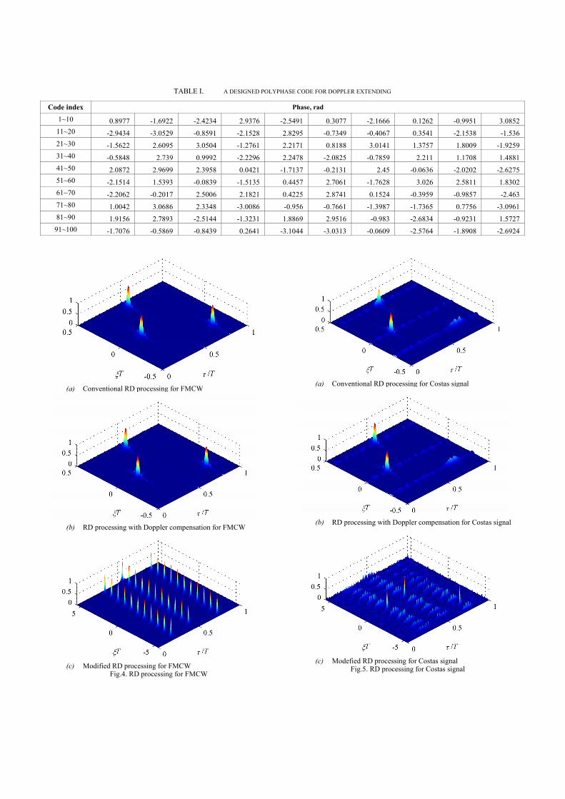
TABLE I. A DESIGNED POLYPHASE CODE FOR DOPPLER EXTENDING
Code index Phase, rad
1~10 0.8977 -1.6922 -2.4234 2.9376 -2.5491 0.3077 -2.1666 0.1262 -0.9951 3.085211~20 -2.9434 -3.0529 -0.8591 -2.1528 2.8295 -0.7349 -0.4067 0.3541 -2.1538 -1.53621~30 -1.5622 2.6095 3.0504 -1.2761 2.2171 0.8188 3.0141 1.3757 1.8009 -1.925931~40 -0.5848 2.739 0.9992 -2.2296 2.2478 -2.0825 -0.7859 2.211 1.1708 1.488141~50 2.0872 2.9699 2.3958 0.0421 -1.7137 -0.2131 2.45 -0.0636 -2.0202 -2.627551~60 -2.1514 1.5393 -0.0839 -1.5135 0.4457 2.7061 -1.7628 3.026 2.5811 1.830261~70 -2.2062 -0.2017 2.5006 2.1821 0.4225 2.8741 0.1524 -0.3959 -0.9857 -2.46371~80 1.0042 3.0686 2.3348 -3.0086 -0.956 -0.7661 -1.3987 -1.7365 0.7756 -3.096181~90 1.9156 2.7893 -2.5144 -1.3231 1.8869 2.9516 -0.983 -2.6834 -0.9231 1.572791~100 -1.7076 -0.5869 -0.8439 0.2641 -3.1044 -3.0313 -0.0609 -2.5764 -1.8908 -2.6924
(a) Conventional RD processing for Costas signal
(b) RD processing with Doppler compensation for Costas signal
(c) Modefied RD processing for Costas signal
Fig.5. RD processing for Costas signal
(a) Conventional RD processing for FMCW
(b) RD processing with Doppler compensation for FMCW
(c) Modified RD processing for FMCW
Fig.4. RD processing for FMCW
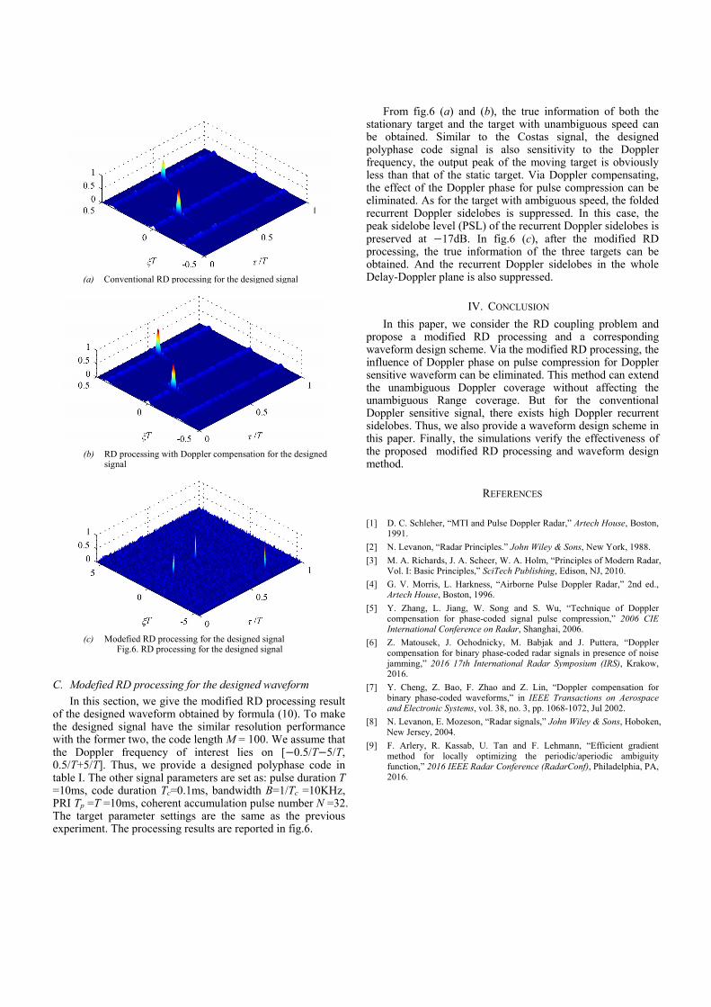
C. Modefied RD processing for the designed waveform In this section, we give the modified RD processing result
of the designed waveform obtained by formula (10). To make the designed signal have the similar resolution performance with the former two, the code length M = 100. We assume that the Doppler frequency of interest lies on [−0.5/T−5/T, 0.5/T+5/T]. Thus, we provide a designed polyphase code in table I. The other signal parameters are set as: pulse duration T =10ms, code duration Tc=0.1ms, bandwidth B=1/Tc =10KHz, PRI Tp =T =10ms, coherent accumulation pulse number N =32. The target parameter settings are the same as the previous experiment. The processing results are reported in fig.6.
From fig.6 (a) and (b), the true information of both the stationary target and the target with unambiguous speed can be obtained. Similar to the Costas signal, the designed polyphase code signal is also sensitivity to the Doppler frequency, the output peak of the moving target is obviously less than that of the static target. Via Doppler compensating, the effect of the Doppler phase for pulse compression can be eliminated. As for the target with ambiguous speed, the folded recurrent Doppler sidelobes is suppressed. In this case, the peak sidelobe level (PSL) of the recurrent Doppler sidelobes is preserved at −17dB. In fig.6 (c), after the modified RD processing, the true information of the three targets can be obtained. And the recurrent Doppler sidelobes in the whole Delay-Doppler plane is also suppressed.
IV. CONCLUSION In this paper, we consider the RD coupling problem and
propose a modified RD processing and a corresponding waveform design scheme. Via the modified RD processing, the influence of Doppler phase on pulse compression for Doppler sensitive waveform can be eliminated. This method can extend the unambiguous Doppler coverage without affecting the unambiguous Range coverage. But for the conventional Doppler sensitive signal, there exists high Doppler recurrent sidelobes. Thus, we also provide a waveform design scheme in this paper. Finally, the simulations verify the effectiveness of the proposed modified RD processing and waveform design method.
REFERENCES
[1] D. C. Schleher, “MTI and Pulse Doppler Radar,” Artech House, Boston, 1991.
[2] N. Levanon, “Radar Principles.” John Wiley & Sons, New York, 1988. [3] M. A. Richards, J. A. Scheer, W. A. Holm, “Principles of Modern Radar,
Vol. I: Basic Principles,” SciTech Publishing, Edison, NJ, 2010. [4] G. V. Morris, L. Harkness, “Airborne Pulse Doppler Radar,” 2nd ed.,
Artech House, Boston, 1996. [5] Y. Zhang, L. Jiang, W. Song and S. Wu, “Technique of Doppler
compensation for phase-coded signal pulse compression,” 2006 CIE International Conference on Radar, Shanghai, 2006.
[6] Z. Matousek, J. Ochodnicky, M. Babjak and J. Puttera, “Doppler compensation for binary phase-coded radar signals in presence of noise jamming,” 2016 17th International Radar Symposium (IRS), Krakow, 2016.
[7] Y. Cheng, Z. Bao, F. Zhao and Z. Lin, “Doppler compensation for binary phase-coded waveforms,” in IEEE Transactions on Aerospace and Electronic Systems, vol. 38, no. 3, pp. 1068-1072, Jul 2002.
[8] N. Levanon, E. Mozeson, “Radar signals,” John Wiley & Sons, Hoboken, New Jersey, 2004.
[9] F. Arlery, R. Kassab, U. Tan and F. Lehmann, “Efficient gradient method for locally optimizing the periodic/aperiodic ambiguity function,” 2016 IEEE Radar Conference (RadarConf), Philadelphia, PA, 2016.
(a) Conventional RD processing for the designed signal
(b) RD processing with Doppler compensation for the designed
signal
(c) Modefied RD processing for the designed signal
Fig.6. RD processing for the designed signal