nrel/cp-500-39481 floating wind turbine systems march 2006
TRANSCRIPT
National Renewable Energy Laboratory Innovation for Our Energy Future
A national laboratory of the U.S. Department of EnergyOffice of Energy Efficiency & Renewable Energy
NREL is operated by Midwest Research Institute ● Battelle Contract No. DE-AC36-99-GO10337
Coupled Dynamic Modeling of Floating Wind Turbine Systems Preprint E.N. Wayman and P.D. Sclavounos Massachusetts Institute of Technology
S. Butterfield, J. Jonkman, and W. Musial National Renewable Energy Laboratory
To be presented at the Offshore Technology Conference Houston, Texas May 1–4, 2006
Conference Paper NREL/CP-500-39481 March 2006

NOTICE
The submitted manuscript has been offered by an employee of the Midwest Research Institute (MRI), a contractor of the US Government under Contract No. DE-AC36-99GO10337. Accordingly, the US Government and MRI retain a nonexclusive royalty-free license to publish or reproduce the published form of this contribution, or allow others to do so, for US Government purposes.
This report was prepared as an account of work sponsored by an agency of the United States government. Neither the United States government nor any agency thereof, nor any of their employees, makes any warranty, express or implied, or assumes any legal liability or responsibility for the accuracy, completeness, or usefulness of any information, apparatus, product, or process disclosed, or represents that its use would not infringe privately owned rights. Reference herein to any specific commercial product, process, or service by trade name, trademark, manufacturer, or otherwise does not necessarily constitute or imply its endorsement, recommendation, or favoring by the United States government or any agency thereof. The views and opinions of authors expressed herein do not necessarily state or reflect those of the United States government or any agency thereof.
Available electronically at http://www.osti.gov/bridge
Available for a processing fee to U.S. Department of Energy and its contractors, in paper, from:
U.S. Department of Energy Office of Scientific and Technical Information P.O. Box 62 Oak Ridge, TN 37831-0062 phone: 865.576.8401 fax: 865.576.5728 email: mailto:[email protected]
Available for sale to the public, in paper, from: U.S. Department of Commerce National Technical Information Service 5285 Port Royal Road Springfield, VA 22161 phone: 800.553.6847 fax: 703.605.6900 email: [email protected] online ordering: http://www.ntis.gov/ordering.htm
Printed on paper containing at least 50% wastepaper, including 20% postconsumer waste

OTC Paper Number 18287
Coupled Dynamic Modeling of Floating Wind Turbine Systems E.N. Wayman and P.D. Sclavounos, Massachusetts Institute of Technology; S. Butterfield, J. Jonkman, and W. Musial, National Renewable Energy Laboratory
Copyright 2006, Offshore Technology Conference This paper was prepared for presentation at the 2006 Offshore Technology Conference held in Houston, Texas, U.S.A., 1–4 May 2006. This paper was selected for presentation by an OTC Program Committee following review of information contained in an abstract submitted by the author(s). Contents of the paper, as presented, have not been reviewed by the Offshore Technology Conference and are subject to correction by the author(s). The material, as presented, does not necessarily reflect any position of the Offshore Technology Conference, its officers, or members. Papers presented at OTC are subject to publication review by Sponsor Society Committees of the Offshore Technology Conference. Electronic reproduction, distribution, or storage of any part of this paper for commercial purposes without the written consent of the Offshore Technology Conference is prohibited. Permission to reproduce in print is restricted to an abstract of not more than 300 words; illustrations may not be copied. The abstract must contain conspicuous acknowledgment of where and by whom the paper was presented. Write Librarian, OTC, P.O. Box 833836, Richardson, TX 75083-3836, U.S.A., fax 01-972-952-9435. Abstract This article presents a collaborative research program that the Massachusetts Institute of Technology (MIT) and the National Renewable Energy Laboratory (NREL) have undertaken to develop innovative and cost-effective floating and mooring systems for offshore wind turbines in water depths of 10−200 m. Methods for the coupled structural, hydrodynamic, and aerodynamic analysis of floating wind turbine systems are presented in the frequency domain. This analysis was conducted by coupling the aerodynamics and structural dynamics code FAST [4] developed at NREL with the wave load and response simulation code WAMIT (Wave Analysis at MIT) [15] developed at MIT.
Analysis tools were developed to consider coupled
interactions between the wind turbine and the floating system. These include the gyroscopic loads of the wind turbine rotor on the tower and floater, the aerodynamic damping introduced by the wind turbine rotor, the hydrodynamic damping introduced by wave-body interactions, and the hydrodynamic forces caused by wave excitation.
Analyses were conducted for two floater concepts coupled
with the NREL 5-MW Offshore Baseline wind turbine in water depths of 10−200 m: the MIT/NREL Shallow Drafted Barge (SDB) and the MIT/NREL Tension Leg Platform (TLP). These concepts were chosen to represent two different methods of achieving stability to identify differences in performance and cost of the different stability methods.
The static and dynamic analyses of these structures
evaluate the systems’ responses to wave excitation at a range of frequencies, the systems’ natural frequencies, and the standard deviations of the systems’ motions in each degree of freedom in various wind and wave environments. This article
explores the effects of coupling the wind turbine with the floating platform, the effects of water depth, and the effects of wind speed on the systems’ performance.
An economic feasibility analysis of the two concepts was
also performed. Key cost components included the material and construction costs of the buoy; material and installation costs of the tethers, mooring lines, and anchor technologies; costs of transporting and installing the system at the chosen site; and the cost of mounting the wind turbine to the platform.
The two systems were evaluated based on their static and
dynamic performance and the total system installed cost. Both systems demonstrated acceptable motions, and have estimated costs of $1.4−$1.8 million, not including the cost of the wind turbine, the power electronics, or the electrical transmission.
1. Introduction A rich wind resource lies untapped off the coasts of the United States with an estimated capacity near 1 TW. This resource is available 5−50 miles off the coast in water depths mostly greater than 30 m. At these depths, the current practice of installing wind turbines on monopiles that are driven into the seabed becomes economically infeasible. The deployment of wind power technology on floating platforms offers a promising solution for offshore wind power at these depths, and a potential alternative to monopiles in shallower water. Previous simulation studies by J. E. Withee [16], K. H. Lee [8] and [9], and K. C. Tong [13] show promising results for the behavior of floating wind turbine systems. However the full coupling between the wind turbine and the floating platform has been observed only to a limited extent, and the optimal design concept for these systems remains unknown. Furthermore, the chore of installing a wind turbine onto a floating platform at sea may make the cost of this technology prohibitive.
This study, therefore, has four goals: (1) to make a first step toward coupling proven codes from the wind power and oil and gas industries to create a tool to model and analyze the behavior of coupled wind turbine and floating platform systems; (2) to study and understand the behavior of these systems in various wind and wave environments; (3) to identify the most cost-effective structures that will provide a solution to the deep water problem; and (4) to avoid the need to install the wind turbine on the platform while at sea.
2 OTC [18287]
The approach was to first examine the mechanisms that
provide stability, and propose two structures that practically isolate different stability mechanisms. The next step was to observe the dynamics of the coupled systems in various wind, wave, and water depth conditions, and evaluate those structures based on static and dynamic performance and an economic analysis.
The two platform concepts presented are the
Massachusetts Institute of Technology/National Renewable Energy Laboratory (MIT/NREL) Shallow Drafted Barge (SDB) and the MIT/NREL Tension Leg Platform (TLP). The MIT/NREL SDB achieves its restoring through high waterplane area, and is hence quite stable during the float-out and installation processes with the wind turbine already mounted. The mooring system of the SDB primarily provides station keeping, and does not contribute to the system’s stability in pitch and roll. Alternatively, the TLP achieves its restoring primarily through its tension leg mooring system, but also has enough hydrostatic and inertial restoring to provide stability during float-out and installation with the turbine already in place.
The following sections outline this process by detailing the
static design process and the static and dynamic analysis processes. The resulting structures and their respective static and dynamic behaviors are then presented and discussed, and then extreme wave events are considered. Finally, a summary of an initial economic analysis is presented that estimates the cost of each structure. The conclusion summarizes the key attributes of each structure and discusses their feasibility.
2. Coordinate System and Modes of System Motion
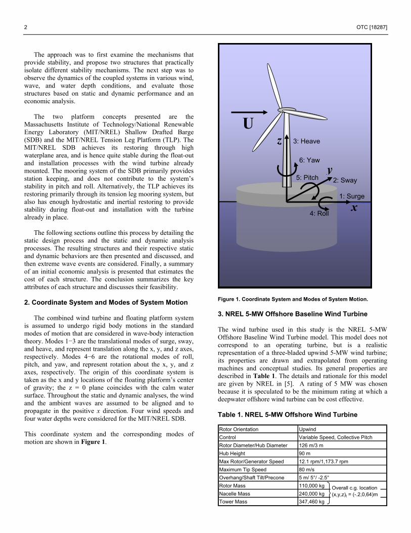
The combined wind turbine and floating platform system is assumed to undergo rigid body motions in the standard modes of motion that are considered in wave-body interaction theory. Modes 1−3 are the translational modes of surge, sway, and heave, and represent translation along the x, y, and z axes, respectively. Modes 4−6 are the rotational modes of roll, pitch, and yaw, and represent rotation about the x, y, and z axes, respectively. The origin of this coordinate system is taken as the x and y locations of the floating platform’s center of gravity; the z = 0 plane coincides with the calm water surface. Throughout the static and dynamic analyses, the wind and the ambient waves are assumed to be aligned and to propagate in the positive x direction. Four wind speeds and four water depths were considered for the MIT/NREL SDB.
This coordinate system and the corresponding modes of motion are shown in Figure 1.
Figure 1. Coordinate System and Modes of System Motion. 3. NREL 5-MW Offshore Baseline Wind Turbine The wind turbine used in this study is the NREL 5-MW Offshore Baseline Wind Turbine model. This model does not correspond to an operating turbine, but is a realistic representation of a three-bladed upwind 5-MW wind turbine; its properties are drawn and extrapolated from operating machines and conceptual studies. Its general properties are described in Table 1. The details and rationale for this model are given by NREL in [5]. A rating of 5 MW was chosen because it is speculated to be the minimum rating at which a deepwater offshore wind turbine can be cost effective. Table 1. NREL 5-MW Offshore Wind Turbine Rotor Orientation UpwindControl Variable Speed, Collective PitchRotor Diameter/Hub Diameter 126 m/3 mHub Height 90 mMax Rotor/Generator Speed 12.1 rpm/1,173.7 rpmMaximum Tip Speed 80 m/sOverhang/Shaft Tilt/Precone 5 m/ 5°/ -2.5°Rotor Mass 110,000 kgNacelle Mass 240,000 kgTower Mass 347,460 kg
Overall c.g. location(x,y,z)t = (-.2,0,64)m
U
x
y
1: Surge
2: Sway
3: Heave
4: Roll
5: Pitch
6: Yaw
z
OTC [18287] 3
The systems were analyzed at four wind speeds to capture
the coupled systems’ performance in representative wind speeds throughout the operational spectrum of the wind turbine. The wind speed of 9 m/s represents region 2 of the power curve. The turbine operates at roughly half of rated power at this wind speed. Its rated power is represented by 11.2 m/s, where it first reaches its rated power. Fifteen m/s represents wind speeds beyond rated wind speed where the wind turbine feathers its blades to maintain rated power; 25 m/s is the cut-out speed, or the highest sustained wind speed where the turbine is in operation. 4. Overall Study Approach This study aims to advance the understanding and feasibility of floating wind turbine systems. Its goals are to study the effects of coupling a wind turbine with a floating structure on the dynamics of the floating system, to explore the effects of environmental conditions, and to identify the most cost-effective floating structures to support a wind turbine that will demonstrate favorable operational performance. To avoid the uncertainty and the cost of mounting a wind turbine to a floating platform at sea, the study seeks to propose concepts for floating structures that will allow the wind turbine to be mounted on the platform on shore or in a shipyard and towed to its installation site already assembled.
To achieve these goals, this study first examines the
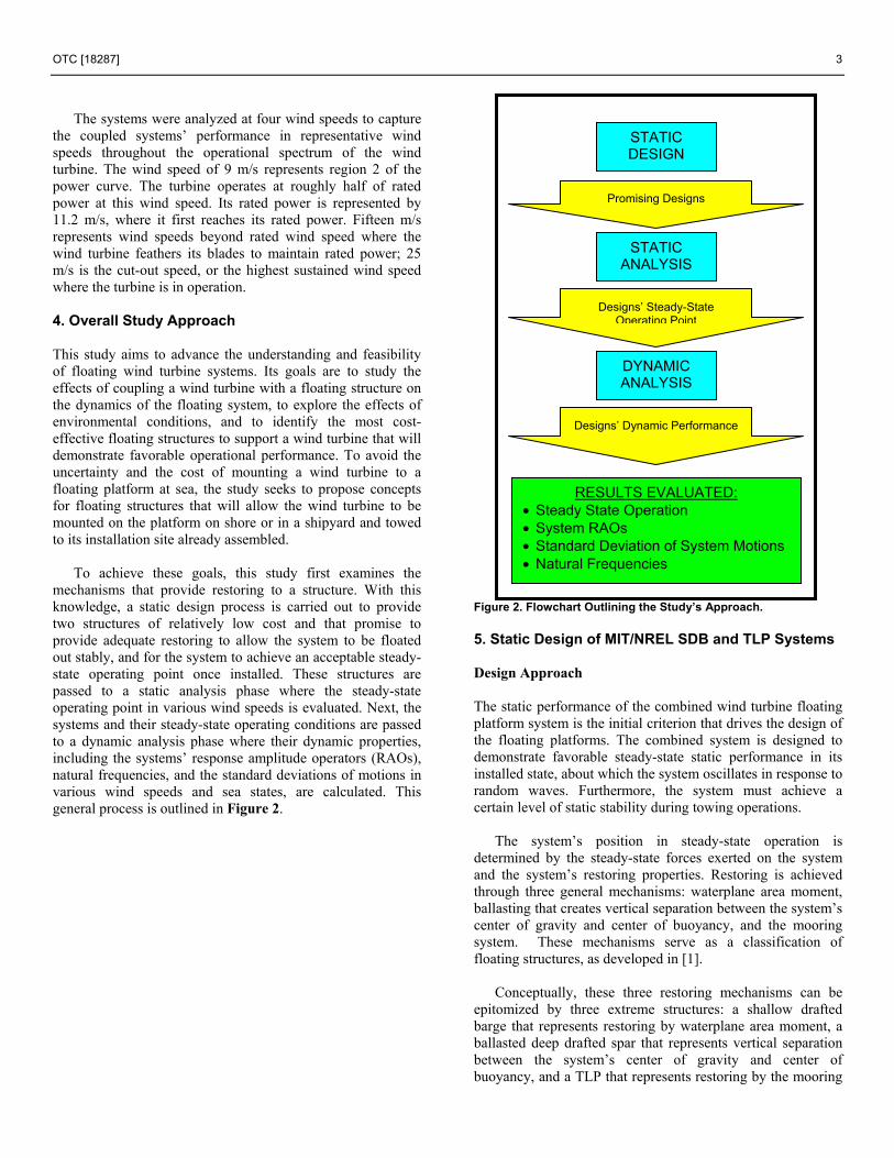
mechanisms that provide restoring to a structure. With this knowledge, a static design process is carried out to provide two structures of relatively low cost and that promise to provide adequate restoring to allow the system to be floated out stably, and for the system to achieve an acceptable steady-state operating point once installed. These structures are passed to a static analysis phase where the steady-state operating point in various wind speeds is evaluated. Next, the systems and their steady-state operating conditions are passed to a dynamic analysis phase where their dynamic properties, including the systems’ response amplitude operators (RAOs), natural frequencies, and the standard deviations of motions in various wind speeds and sea states, are calculated. This general process is outlined in Figure 2.
F
igure 2. Flowchart Outlining the Study’s Approach.
5. Static Design of MIT/NREL SDB and TLP Systems Design Approach
The static performance of the combined wind turbine floating platform system is the initial criterion that drives the design of the floating platforms. The combined system is designed to demonstrate favorable steady-state static performance in its installed state, about which the system oscillates in response to random waves. Furthermore, the system must achieve a certain level of static stability during towing operations.
The system’s position in steady-state operation is determined by the steady-state forces exerted on the system and the system’s restoring properties. Restoring is achieved through three general mechanisms: waterplane area moment, ballasting that creates vertical separation between the system’s center of gravity and center of buoyancy, and the mooring system. These mechanisms serve as a classification of floating structures, as developed in [1].
Conceptually, these three restoring mechanisms can be
epitomized by three extreme structures: a shallow drafted barge that represents restoring by waterplane area moment, a ballasted deep drafted spar that represents vertical separation between the system’s center of gravity and center of buoyancy, and a TLP that represents restoring by the mooring
STATIC ANALYSIS
STATIC DESIGN
DYNAMIC ANALYSIS
Designs’ Steady-State Operating Point
RESULTS EVALUATED: • Steady State Operation • System RAOs • Standard Deviation of System Motions • Natural Frequencies
Promising Designs
Designs’ Dynamic Performance

4 OTC [18287]
system. These restoring methods and their representative structures are shown in gray in Figure 3.
Figure 3. Restoring Mechanisms and Representative Structures.
This study examines the behavior and cost of the most practical representation of these extreme structures. Structures studied are the MIT/NREL SDB and the MIT/NREL TLP that achieve restoring primarily through waterplane area moment and the mooring system, respectively. These structures are shown in red in Figure 3. The extreme of ballasting was not presented here because an initial consideration of that structure type showed that the draft required to create enough inertial restoring rendered its construction infeasible for any realistic shipyard and port.
The following sections outline the static design process
used to arrive at the specifications for the MIT/NREL SDB and the MIT/NREL TLP. Static Design of the MIT/NREL SDB
The MIT/NREL SDB is intended to represent the
waterplane area method of achieving restoring. However, the structure also contains ballast to achieve a reasonable draft. Therefore, the MIT/NREL SDB achieves the required restoring through an optimal mix of waterplane area and ballast.
A static design and analysis phase is initially carried out,
calling on theory developed in [3] and [11], to determine the optimal size and shape of the MIT/NREL SDB that will provide sufficient stability in unmoored operating conditions. Once moored, the mooring lines are assumed to provide station-keeping functions only. Therefore, the MIT/NREL SDB system is assumed to experience restoring from its mooring lines only in surge, and is required to demonstrate acceptable static and dynamic behavior in all other modes of motion during full operation mode without additional restoring from mooring lines in those modes.
The optimal size and shape are determined by solving for the platform geometry that limits the static steady-state pitch of the combined platform-wind turbine system to a pitch angle below a designated threshold value. The system must maintain an acceptable steady-state pitch angle in maximum wind loading conditions that it would experience during operation.
The steady-state pitch is determined by the pitch moment
on the system and the system’s restoring properties in pitch, as shown in the following equation.
55
55
FC
ξ =
where F5 is the pitch moment about the origin of the
coordinate system generated by the wind loading on the wind turbine, denoted by FThrust. This moment is given here.
5 Thrust HubF F Z= In the case of the MIT/NREL SDB, restoring is achieved
through hydrostatics (waterplane area moment and the location of the center of buoyancy) and inertia (ballasting, and location of the center of mass). The hydrostatic and inertial restoring coefficient in pitch for a cylindrical, surface-piercing cylinder is shown in the following equation
4
55, & 11 4H I B B G
RC F Z M gZ gρ π= − +
where FB and ZB represent buoyant force and center of
buoyancy, M11, the total system mass, ZG, the center of gravity, ρ, the density of sea water, and R, the cylinder radius.
It is speculated that beyond a pitch angle of 10 degrees, the
wind turbine will lose substantial efficiency. Therefore, the threshold pitch value in this study was taken as 10 degrees. The maximum wind loading was taken as 800,000 N, which is the steady state thrust at a wind speed of 11.2 m/s and acts on the wind turbine hub, at ZHub = 91.5 m. The necessary restoring coefficient is found by solving for the restoring coefficient needed to limit the pitch to 10 degrees, as shown here.
[ ]8555
5
800,000 91.5 4.2 10.1745
F N mC Nradξ
× −⎡ ⎤= = = −⎢ ⎥⎣ ⎦m
A sufficient restoring coefficient can be achieved by
adjusting the draft and radius of the platform, and by pouring concrete inside the cylinder to add ballast. The resulting dimensions and properties of the MIT/NREL SDB are listed in Table 2.
OTC [18287] 5
Table 2. MIT/NREL SDB Properties
Cylinder Radius 18 m
Cylinder Height 6.5 m
Concrete Ballast Height 1.65 m
Steel Thickness 0.01 m
Installed Draft 5 m
Deck Clearance 1.5 m
Steel Mass 218 metric ton
Concrete Mass 4299 metric ton
Turbine Mass 698 metric ton
Total Mass 5210 metric ton
Buoyant Mass 5210 metric ton
Reserve Buoyancy 0 kg
Center of Gravity 4.25 m
Center of Buoyancy -2.5 m
C55 4.84E+08 N-m Static Design of the MIT/NREL TLP
The MIT/NREL TLP is intended to represent a structure
that achieves its restoring through a tension leg mooring system. This results in a system that is stiff in pitch relative to the MIT/NREL SDB, with significant force exerted by the tethers. A static design process along the lines of [16] and utilizing the theory developed in [3] and [11] is carried out to determine the tether tension and dimensions of the TLP.
The restoring coefficient in pitch provided by the tethers is
shown here.
( ) ( )2
55, 2 TethersTethers Tethers
Tethers
EAC R
L= + F T
where (EA)Tethers is the elastic modulus times the cross
sectional area of the tethers, LTethers is the unstretched length of the tethers, R is the cylinder radius (or the radial distance to the tether fairlead), FTethers is the total force exerted by the tethers, and T is the cylinder draft (or the vertical distance to the tether fairlead).
This equation shows the relationship of this restoring term
to the elastic stiffness of the tethers. This study considers the rigid body motions, hence elastic modes of motion are out of the study’s scope, and the tethers are taken to be infinitely stiff. This assumption drives the restoring in pitch from the tethers toward infinity.
( )TethersEA → ∞
55,TethersC⇒ → ∞ This stiffness prevents any significant motion in pitch, roll,
and heave, and the platform’s motions are therefore limited to surge, sway, and yaw. The mooring system must be designed to adequately limit motions in these modes.
A tension leg mooring system must also maintain reasonable tension in all of its tethers. With the steady-state wind force acting in the positive x direction, the tension in tether 3 increases and the tension in tether 1 decreases to provide a balance of forces and moments. The initial tether tension must be chosen to ensure that the tension in the windward tether does not exceed the maximum allowable tension and the tension in the leeward tether does not drop below the minimum allowable tension.
A drawback of a conventional TLP is that the system has
low or negative restoring properties without its mooring system, which renders it unable to float upright on its own. This attribute would require the wind turbine to be mounted to the floating platform only after the platform is installed and the tethers tensioned.
To avoid mounting the wind turbine at sea, the size and
shape of the floating platform must be chosen to provide the structure with significant restoring during towing and installation. The restoring during these processes is provided in part by water ballast inside the structure. Once the system reaches its installation site, it is hooked to its tethers, and deballasted to pretension the tethers. This pretensioning process requires the weight of the water ballast inside the structure to equal the total tension force desired.
To summarize, the tether tension for this system must
fulfill three requirements: (1) the tethers must provide sufficient restoring in surge to adequately limit the steady-state offset in surge; (2) the tension of the windward tether must never exceed the maximum allowable tension, and the leeward tether must never go slack or fall below the minimum allowable tension at any point during operation; and (3) the total force exerted by the tethers must match the weight of the water required to ballast the system for stability during installation.
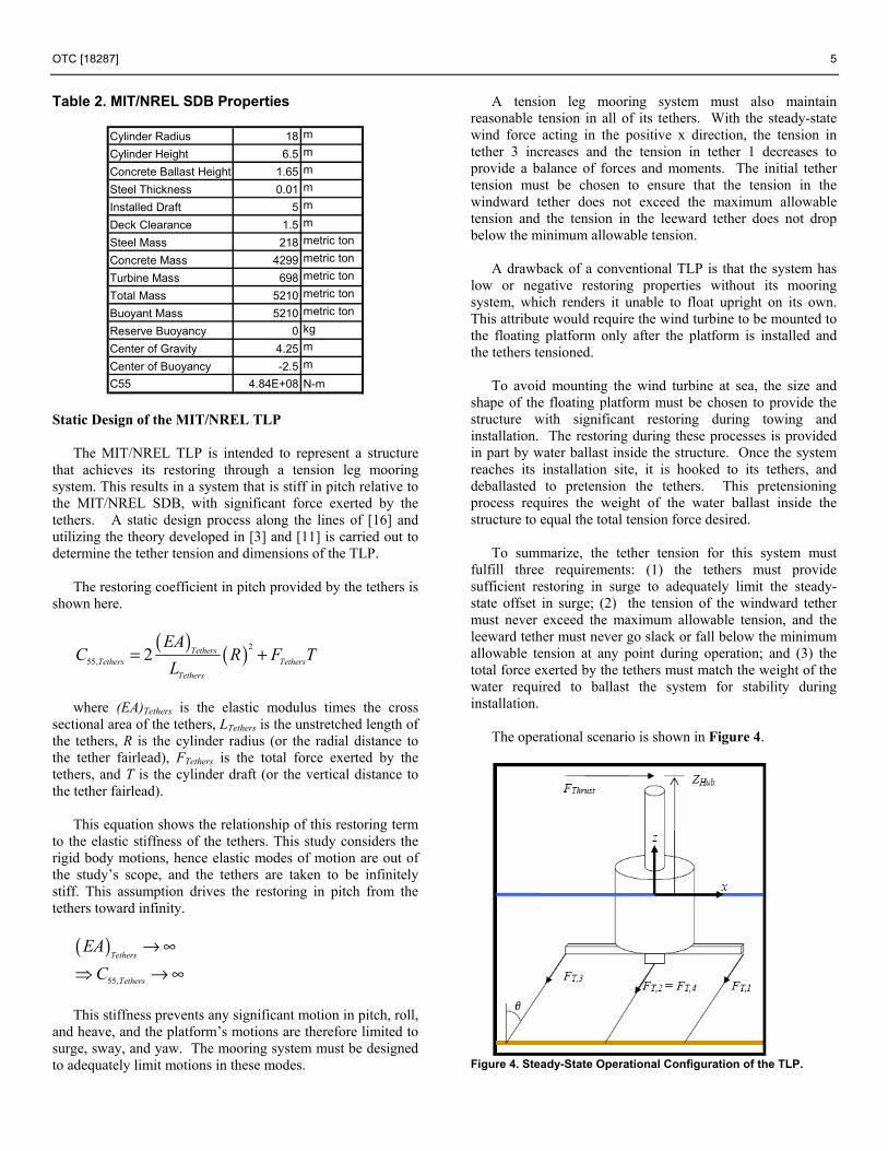
The operational scenario is shown in Figure 4.
Figure 4. Steady-State Operational Configuration of the TLP.

6 OTC [18287]
Under steady-state conditions, the platform will achieve its steady-state displacement in surge. At this displacement, the tethers will form an angle with the vertical, shown as θ in Figure 4. The tethers must be of sufficient tension to provide adequate restoring to limit this angle to about 5 degrees to prevent the system from experiencing highly nonlinear restoring and displacement.
Restoring in surge caused by the tethers is related to the
tether tension and length through the following equation.
11Tethers
Tethers
FCL
=
Restoring results in steady-state displacement through the
following relation.
11
11 11
ThrustFFC C
ξ = =
An initial limit for the tether tension is reached by limiting
the system’s steady-state displacement. This tension must also satisfy the second requirement for
the operational line tension. In operating conditions, the tension in each line is found by solving a balance of forces and moments for the tensions. As indicated in Figure 4, the tethers are numbered 1 through 4, where at rest the fairlead and anchor of tether 1 align with the positive x axis, tether 2, the positive y axis, tether 3, the negative x axis, and tether 4, the negative y axis. Assuming that the wind always propagates in the positive x direction, tether 3 is always the upwind tether and tether 1 is always the downwind tether.
A balance of forces in the vertical direction requires the
buoyancy force plus the additional buoyancy gained by the setdown of the structure as shown in Figure 4. The system weight must equal the downward component of the sum of the tether tensions. This balance of forces is shown in the following equation, where θ represents the angle that the tethers make with the vertical.
( )211 ,cos cosB Tether Tether T iF g R L L M g Fρ π θ θ+ − − = ∑
Employing the small angle approximation that cos θ is
about equal to 1 and that sin θ is about equal to θ, this equation simplifies to
11 ,B T iF M g F− =∑ With four tethers spaced at 90-degree intervals around the
structure, FT,ave, the average tether tension is found by dividing the total tension force by four. Because tethers 2 and 4 are not affected by the moment exerted on the structure, they are assumed to have tensions equal to the average tension.
( )211
,2 ,4 ,
cos4cos
B Tether TetherT T T ave
F g R L L M gF F F
ρ π θθ
+ − −= = =
Again invoking the small angle approximation, the tension
in tethers 2 and 4 is given by
11,2 ,4 , 4
bT T T ave
F M gF F F −= = =
The tethers of concern are tethers 1 and 3, which are at risk
of going slack or exceeding the maximum allowable tension, respectively. To balance the moment exerted on the system, tether 3 has a tension of FT,ave plus an additional tension, ∆F. To maintain the balance of forces in the vertical direction, tether 1 must then have a tension of FT,ave minus ∆F. This balance of moments is given by the following equation.
( ) ( )5 ,3 ,1 , ,cos cos cos cosT T T ave T aveF F R F R F F R F F Rθ θ θ= − = + ∆ − − ∆ θ
)
Employing the small angle approximation, this equation
simplifies to the following equation.
( ) (5 ,3 ,1 , ,T T T ave T aveF F R F R F F R F F R= − = + ∆ − − ∆
The initial line tension must be chosen to prevent the tensions in the individual tethers from going to zero or exceeding the maximum allowable tension.
The final requirement is that this tether tension must be
equal to the weight of the water used as ballast to stabilize the system during towing and installation.
The maximum force that the system is expected to
experience during towing is taken as the minimum thrust exhibited by the turbine during its operation, 250,000 N. The turbine will clearly not be operating during towing and installation, so the wind loading on the structure will certainly be lower than any wind loading during operation. Therefore, the minimum operational thrust serves as a definite upper bound to the installation wind loading.
Again, the system is required to achieve adequate
hydrostatic and inertial restoring to limit the steady-state pitch to less than 10 degrees during towing and installation. This limit was chosen to ensure that the system will remain almost vertical during installation processes, allowing the installers to tow the system with little stabilization required. To enforce this requirement, the minimum hydrostatic and inertial restoring coefficient required during towing can be found with the following equation.
[ ]8555, & ,min
5
250,000 91.5 1.3 10.1745H I
F N mC Nradξ
× −⎡ ⎤= = = −⎢ ⎥⎣ ⎦m
This restoring is achieved by adjusting the cylinder height
and radius and the level of concrete ballast.

OTC [18287] 7
The requirements outlined above are considered together to arrive at the TLP’s size, shape, and tether tension. The system properties that result from this iterative static design process are summarized in Table 3. Table 3. Properties of the MIT/NREL TLP in Operating and Towing Conditions Ststem Properties
Radius 11.00 m
Cylinder Height 21.5 m
Concrete Ballast Height 4.5 m
Steel Thickness 0.01 m
Steel Mass 176 metric ton
Concrete Mass 4375 metric ton
Turbine Mass 698 metric ton
System in Towing Conditions
Water Ballast Height 6.55Water Mass 2548 metric tonTotal Mass 7798 metric tonTowing Draft 20.01Deck Clearance 1.49Center of Gravity -11.07Center of Buoyancy -10.01C55,Towing 1.97E+08 N-m
System in Installed, Operating Conditions
Number of Tethers 4FTethers,Total 2.50E+07 NFTethers,each 6.25E+06 NFTethers,max [14] 2.38E+07 N∆F 3.33E+06 NFT,3 9.58E+06 NFT,1 2.92E+06 NInstalled Draft 20.01 m
Deck Clearance 1.49 m
Total Mass 5249 metric tonBuoyant Mass 7797 metric ton
Reserve Buoyancy 48.54%Center of Gravity -9.40 mCenter of Buoyancy -10.01 m
6. Static and Dynamic Analysis Process The combined wind turbine and floating platform systems were analyzed in the frequency domain by following the process outlined in Figure 5.
Figure 5. Flowchart for the Static and Dynamic Analysis Process.
Inputs to this analysis process are shown in blue in this figure, analysis modules are shown in yellow, quantities passed between the modules are shown along the arrows, and the final outputs are shown in green.
This process first takes the platform and wind turbine
geometry and inertia, the steady-state thrust of the wind turbine, and the tether configuration into the STATIC ANALYSIS module. This module calculates the steady forces on the system and the system’s restoring, and computes the steady-state operating point, summarized by the six element vector, ξ.
This steady-state operating point is passed to the FAST
module that calculates the linearized properties of the wind turbine. These include the wind turbine’s mass, damping, and stiffness matrices that incorporate contributions from aerodynamics and gyroscopics, shown in Figure 5 as MWT, BWT, CWT, respectively. The platform geometry and water depth are then passed to WAMIT, which calculates the platform’s mass, added mass, damping and stiffness matrices, and exciting forces MFP, AFP(ω), BFP(ω), CFP, and XFP(ω) at each frequency.
The matrices for the wind turbine and the platform are then
passed to the DYNAMIC ANALYSIS module, where they are combined to represent the coupled system, and the RAOs, natural frequencies, and standard deviations of motions of the combined system are calculated.
The details of the calculations performed in each module
are detailed in the following sections. Steady-State Operating Point
A static analysis is first carried out to determine the
steady-state operating configuration of the combined wind turbine-floating platform system in its moored condition. This configuration is governed by the static equilibrium equation, summarized in matrix form:
[ ]&H I Tethers Steady SteadyState State
C C F⎛ ⎞ ⎛+ Ξ =⎜ ⎟ ⎜⎝ ⎠ ⎝
⎞⎟⎠
R
where CH&I and CTethers represent the six-by-six restoring
matrices from the hydrostatics and inertia from the tethers, respectively, Ξ represents the six-element steady-state displacement vector, and F represents the six-element steady-state force and moment vector exerted on the system by the wind.
Assuming small rotations and displacements, the restoring
coefficients are as follows. The hydrostatic and inertial restoring matrix for a surface-piercing cylinder contains all zeros except for the 33, 44, and 55 entries, which are defined here.
2
33, &H IC gρ π=

8 OTC [18287]
4
44, & 11 4H I b b g
g RC F z M gz ρ π= − +
4
55, & 11 4H I b b g
g RC F z M gz ρ π= − +
The restoring matrix for a tension leg mooring system
contains all zeros except the following entries. As explained in Section 5, the tethers of the tension leg mooring system are modeled as infinitely stiff tethers to model purely rigid body motions. This drives C33,Tethers, C44,Tethers, and C55,Tethers toward infinity.
11,Tethers
TethersTethers
FCL
=
22,Tethers
TethersTethers
FCL
=
33,Tethers Tethers
TethersTethers
E ACL
= → ∞
( )2
44, 112 (T TTethers Fairlead B
T
E AC R F M gL
= + − )T → ∞
( )2
55, 112 ( )T TTethers B
T
E AC R F M gL
= + − T → ∞
( ) ( )2
66, 11Fairleed
Tethers bTethers
RC F
L= − M g
51, 42,Tethers
Tethers TethersTethers
FC CL
= = − T
ω
The MIT/NREL SDB is intended to represent a system that
achieves stability through waterplane area. A mooring system is used with this design for station keeping only. Therefore, restoring is assumed to be provided only by the mooring lines in the mode of surge.
Steady-state static displacement is then calculated as
follows.
[ ] 1
&Steady H I Tethers SteadyState State
C C F− ⎛ ⎞Ξ = + ⎜ ⎟⎝ ⎠
Response Amplitude Operators
The RAOs are calculated in the DYNAMIC ANALYSIS
module for the combined wind turbine and floating platform system.
The equations of motion that govern the linear dynamic
motions of the system are summarized in matrix form:
( )( ) ( ) ( ) ( )2 M A i B C Xω ω ω ω ω⎡ ⎤− + + + Ξ =⎣ ⎦
where M, A(ω), B(ω), and C represent the 6 by 6
combined mass, added mass, damping, and stiffness matrices, respectively, and X(ω), the six-by-one vector that contains the hydrodynamic exciting forces. These matrices are the superposition of the matrices calculated by the FAST module for the wind turbine and by the WAMIT module for the floating platform.
The mass matrix can be found easily, while the added mass matrix, the damping matrix, and exciting forces are evaluated by WAMIT and FAST. The restoring matrix represents the restoring from hydrostatics and inertia, as developed in the previous section.
The symbol Ξ(ω) represents the system’s dimensional
response in each mode of motion at each frequency. The RAO is then reported as the dimensionless motion, made nondimensional.
For the translational modes of motion, the RAO is given
by
( )( ) ii
wave
wRAO wA
Ξ= i = 1,2,3
and for the rotational modes of motion, the RAO is given by
( )( )/
ii
wave
RAOA R
ωω Ξ= i = 4,5,6
where the subscript i denotes the mode of motion, Awave
represents the wave amplitude, and R is the cylinder radius. Although the RAOs are independent of the sea state, the
damping and stiffness properties of the wind turbine depend on wind speed, which causes the RAOs of the combined system to depend on wind speed.
Natural Frequencies
The natural frequencies of the combined wind turbine and
floating platform system can be estimated by considering the system’s restoring and inertial properties.
*(0)
iii
ii ii
CM A
ω =+
where the subscript i indicates the mode of motion, and the
0 indicates the zero-frequency limit of the added mass. In weakly restored modes of motion, the natural frequency
will be calculated as zero. These modes of motion, however, pick up a natural frequency through cross coupling to other modes of motion. In this case, the natural frequencies can be

OTC [18287] 9
determined graphically, by examining the frequency at which the peak of the RAO occurs.
Standard Deviation of System Motions
By virtue of linear system theory, once the RAOs of the system have been determined, the variance and standard deviation of the system motions in various sea states can be ascertained [12]. An assumption of linear system theory is that given a Gaussian input signal, the output of the linear system will also be Gaussian with a variance determined by the Wiener-Khinchine theorem, which is shown in the following equation for the translational modes:
( ) 22
i iS RAO dξ ζσ ω= ∫ ω i = 1,2,3,
and by the equation below for the rotational modes,
( )2
22i
iRAOS
Rξ ζσ ω= ∫ dω i = 4,5,6
where 2
iξσ represents the variance of system motion in
mode i, Sζ (ω), the spectral density of the ambient waves in
the given sea state, ω , the wave frequency, and R, the radius that was used originally to make the RAO non-dimensional.
The spectral density for fully developed seas has been
defined by the International Ship Structures Committee (ISSC) and the International Towing Tank Conference (ITTC) [12].
( ) ( )5
2 .11 exp .442 2 2
m ms m
TS H Tζ
ω ωωπ π π
− ⎧⎪⎛ ⎞ ⎛ ⎞⎛ ⎞= ⎨ ⎬⎜ ⎟⎜ ⎟ ⎜ ⎟⎝ ⎠⎝ ⎠ ⎝ ⎠⎪⎩
4T − ⎫⎪
⎪⎭
Hs and Tm represent significant wave height and mean period in the given sea state, respectively. The DYNAMIC ANALYSIS module performs this calculation to give the standard deviation of the system motion in 5 sea states defined in Table 4.
Table 4. Sea State Definition
Sea State Hs [m] Tm [s]
1 0.09 2.02 0.67 4.83 2.44 8.14 5.49 11.35 10.00 13.6
Analyses were performed by following this entire process
for the MIT/NREL SDB and TLP in various wind, wave, and water depth conditions. Results are reported in the sections that follow to illustrate the effects of coupling the wind turbine with the floating platform, the effects of water depth, and the effects of wind speed.
7. Static and Dynamic Analysis of the MIT/NREL SDB
The MIT/NREL SDB is presented at water depths of 10−100 m. An analysis at 10 m was performed to examine the SDB as a potential alternative to monopiles in shallow water. At 30 m, monopiles become technically and economically challenging to install. The NREL baseline water offshore site is 62.5 m deep. Finally, an analysis was performed at 100 m to illustrate the trends in behavior of the SDB as depth increases.
The wind speed of 11.2 m/s and the water depth of 62.5 m
were chosen as the base-case conditions for this analysis because they represent likely operating conditions that will be easily compared to other NREL studies.
Static Analysis of the MIT/NREL SDB
The steady-state static equation of motion was solved at
four wind speeds that represent various zones of the power curve. The results of steady-state pitch in these wind speeds are summarized in Table 5. Table 5. Steady-State Pitch of the SDB in Various Steady Wind Speeds
Wind Speed Thrust Restoring Pitch[m/s] [kN] [N-m] [deg]
9 600 4.84E+08 6.49911.3 800 4.84E+08 8.66515 500 4.84E+08 5.41625 400 4.84E+08 4.333
Dynamic Analysis of the MIT/NREL SDB
The results of the dynamic analysis consist of the RAOs,
the natural frequencies, and the standard deviations of the system motions. The RAOs for each analysis case will appear at the end of the section; the other results will be reported in the body of this section.
Base-Case – Coupled System Effects The results of the dynamic analysis are first presented in
Figure 6 for the base-case scenario of 11.2 m/s winds and 62.5-m water depth.
The RAOs of the combined wind turbine and floating
platform are shown in Figure 6. Although the system is excited by wind and waves only in the modes of surge, heave, and pitch, it displays motion in the modes of sway, roll, and yaw as well. The system’s response in these modes indicates the effects of the coupling mechanisms that result from combining the wind turbine with the floating platform. The response in these modes, however, is quite small compared to the dominant modes.
The RAOs also indicate a strong response at the system’s
resonant frequencies. The resonant frequencies are listed in

10 OTC [18287]
Table 6. As explained in Section 6, although the modes of sway and yaw have no restoring, these modes of motion pick up a natural frequency through cross coupling effects, and are determined graphically from the system’s RAOs in Figure 6. Finally, the standard deviations of the system motions in 5 sea states are summarized in Table 7. Table 6. Natural Frequencies of the MIT/NREL SDB
Mode Natural FrequencySurge 0.769 [rad/s]Sway 0.769 [rad/s]Heave 0.650 [rad/s]Roll 0.455 [rad/s]Pitch 0.457 [rad/s]Yaw 0.457 [rad/s]
Table 7. Standard Deviation of System Motions of the MIT/NREL SDB in Wind Speed of 11.2 m/s, Water Depth of 62.5 m, and Various Sea States
Sea State 1 2 3 4 5Hs [m] 0.09 0.67 2.44 5.49 10Tm [s] 2 4.8 8.1 11.3 13.6
Surge [m] 0.00038 0.19875 1.32242 1.96520 2.66969Sway [m] 0.00000 0.00006 0.01114 0.03916 0.06198Heave [m] 0.00004 0.09430 0.62427 1.40341 2.53490Roll [deg] 0.00000 0.00030 0.02239 0.07584 0.11748Pitch [deg] 0.00002 0.01448 0.21819 0.62477 1.02926Yaw [deg] 0.00000 0.00142 0.02994 0.10242 0.17075 For the MIT/NREL SDB, Table 7 shows increasing
standard deviations of system motions with increasing severity of sea state. This can be attributed to the shape of the RAOs and the shape of spectral densities describing different sea states. At lower sea states, the spectral density has a large spread, and is centered around relatively high frequencies. As the severity of the sea state increases, its spectral density becomes more narrow-banded, and centered around lower frequencies. The standard deviation of system motions increase with increasing sea state because the MIT/NREL SDB’s natural frequencies are low compared to the frequencies where the peak of the spectral densities occur. As the sea state increases, the peak of the spectral density approaches the natural frequency, which results in an increasing response with increasing sea state.
These results show the importance of considering the sea
state properties of a site chosen for the installation of a floating structure. The structure must be tuned to achieve RAOs whose peaks are not coincident with the peak of the spectral density describing the likely sea state at that site.
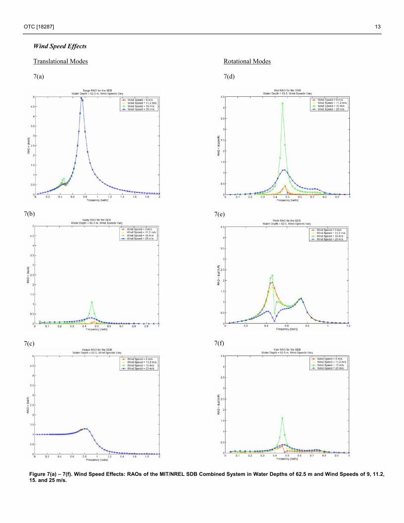
Wind Speed Effects The effects of various wind speeds on the combined
system’s RAOs are shown in Figure 7. These RAOs are calculated at the base-case water depth of 62.5 m.
The results plotted for the wind speed effects of the MIT/NREL SDB combined system once again show proof of coupling between the modes of motion. The RAOs in pitch and roll indicate that this coupling weakens in region 2 of the wind turbine power curve, as the wind turbine increases its power generated with wind speed to rated power, and strengthens beyond rated power. This effect is due to the cross coupling terms of the wind turbine matrices. Cross coupling damping terms are lowest at 15 m/s, and highest at 11 m/s, while the cross coupling inertial terms are highest at 15 m/s, and lowest at 11 m/s.
The natural frequencies of the system, which are
summarized in Table 8, remain fairly constant in various wind speeds. The standard deviations of system motions in various wind speeds are also summarized in Table 9.
Table 8. Natural Frequencies of the MIT/NREL SDB in 62.5-m Water Depth and Various Wind Speeds
Wind Speed [m/s] 9 11.2 15 25Surge [rad/s] 0.7689 0.7689 0.7689 0.7689Sway [rad/s] 0.7689 0.7689 0.7689 0.7689Heave [rad/s] 0.6496 0.6496 0.6496 0.6496Roll [rad/s] 0.4522 0.4548 0.4526 0.4530Pitch [rad/s] 0.4541 0.4568 0.4546 0.4539Yaw [rad/s] 0.4541 0.4568 0.4546 0.4539
Table 9. Standard Deviations of System Motions of the NREL/MIT SDB in 62.5-m Water Depth and Various Wind Speeds
Hs [m] 0.09 0.67 2.44 5.49 10Tm [s] 2 4.8 8.1 11.3 13.6
9 m/s 0.000 0.200 1.324 1.967 2.67311.2 m/s 0.000 0.199 1.322 1.965 2.67015 m/s 0.000 0.200 1.326 1.988 2.71525 m/s 0.000 0.200 1.332 1.977 2.676
9 m/s 0.000 0.000 0.012 0.042 0.06611.2 m/s 0.000 0.000 0.011 0.039 0.06215 m/s 0.000 0.000 0.113 0.484 0.79025 m/s 0.000 0.000 0.053 0.241 0.439
9 m/s 0.000 0.094 0.623 1.403 2.53511.2 m/s 0.000 0.094 0.624 1.403 2.53515 m/s 0.000 0.094 0.622 1.404 2.53925 m/s 0.000 0.094 0.622 1.405 2.540
9 m/s 0.000 0.000 0.019 0.071 0.11211.2 m/s 0.000 0.000 0.022 0.076 0.11715 m/s 0.000 0.001 0.189 0.768 1.23525 m/s 0.000 0.003 0.112 0.374 0.608
9 m/s 0.000 0.015 0.225 0.675 1.11811.2 m/s 0.000 0.014 0.218 0.625 1.02915 m/s 0.000 0.015 0.215 0.653 1.08925 m/s 0.000 0.015 0.163 0.320 0.517
9 m/s 0.000 0.001 0.021 0.081 0.14211.2 m/s 0.000 0.001 0.030 0.102 0.17115 m/s 0.000 0.002 0.076 0.304 0.49425 m/s 0.000 0.002 0.042 0.137 0.230
Pitch [deg]
Yaw [deg]
Sea States
Surge [m]
Sway [m]
Heave [m]
Roll [deg]

OTC [18287] 11
As the RAOs suggest, the standard deviations of the
system motions decrease with wind speed in region 2 of the power curve, where the wind turbine damping plays an increasingly larger role. The standard deviations of motions increase in region 3, as the wind turbine begins to feather its blades, reducing its damping. The motions then decrease again at very high wind speeds. Again, the cross-coupling effects are visible in the standard deviations of the system motions, most notably in roll at the wind speed of 15 m/s.
Water Depth Effects Due to the shallow draft of the SDB, this structure has
potential to be deployed in very shallow water as a possible alternative to monopile foundations. This shallow draft could also lead to the potential for slamming and other nonlinear effects in deeper open water, where large waves are more likely to develop. The effects of water depth on the MIT/ NREL SDB system are shown in water depths of 10, 30, 62.5, and 100 m, at the base-case wind speed of 11.2 m/s for (see Figure 8). These numbers show once again the coupling between modes of motion, and also show that surge motions increase with water depth, where as pitch motions decrease with water depth.
The natural frequencies for this system in the water depths
listed above are apparent in the RAOs, and are summarized in Table 10. Table 10. Natural Frequencies of the MIT/NREL SDB in 11.2 m/s Wind Speeds and Various Water Depths Water Depth [m] 10 30 62.5 100Surge [rad/s] 0.7270 0.7657 0.7689 0.7692Sway [rad/s] 0.4403 0.4543 0.4548 0.4549Heave [rad/s] 0.4024 0.5749 0.6496 0.6782Roll [rad/s] 0.4403 0.4543 0.4548 0.4549Pitch [rad/s] 0.4424 0.4563 0.4568 0.4569Yaw [rad/s] 0.4424 0.4563 0.4568 0.4569
These natural frequencies remain fairly constant across
water depths, increasing only slightly with increasing depth. The only term factoring into the natural frequencies that is affected by water depth is the zero-frequency added mass term. Because this term only varies slightly with water depth, the natural frequencies remain fairly constant.
The RAOs of the SDB in various water depths result in the
standard deviations of system motions summarized in Table 11.
The values of the standard deviations of motion for various water depths show that although the cross coupling in the system excites motion in modes not directly excited by the wind and waves, the motions excited by cross coupling alone are highly tuned to a certain frequency and do not result in large standard deviations of motion. Furthermore, the results over the water depths show that the standard deviations of
motions generally decrease with water depth. This trend is due to decreasing added mass with increasing water depth. Table 11. Standard Deviations of System Motions of the NREL/MIT SDB in 11.2 m/s Wind Speeds and Various Water Depths
Hs [m] 0.09 0.67 2.44 5.49 10Tm [s] 2 4.8 8.1 11.3 13.6
10 m 0.000 0.186 1.107 1.872 2.88630 m 0.000 0.204 1.350 2.042 2.82662.5 m 0.000 0.199 1.322 1.965 2.670100 m 0.000 0.198 1.316 1.945 2.626
10 m 0.000 0.000 0.019 0.073 0.11930 m 0.000 0.000 0.013 0.047 0.07562.5 m 0.000 0.000 0.011 0.039 0.062100 m 0.000 0.000 0.011 0.037 0.058
10 m 0.000 0.056 0.613 1.526 2.75930 m 0.000 0.094 0.627 1.411 2.54762.5 m 0.000 0.094 0.624 1.403 2.535100 m 0.000 0.094 0.624 1.402 2.533
10 m 0.000 0.000 0.030 0.111 0.17530 m 0.000 0.000 0.026 0.090 0.14062.5 m 0.000 0.000 0.022 0.076 0.117100 m 0.000 0.000 0.021 0.072 0.111
10 m 0.000 0.013 0.304 1.143 2.04130 m 0.000 0.015 0.245 0.760 1.27662.5 m 0.000 0.014 0.218 0.625 1.029100 m 0.000 0.014 0.212 0.587 0.956
10 m 0.000 0.001 0.044 0.186 0.33530 m 0.000 0.001 0.035 0.126 0.21362.5 m 0.000 0.001 0.030 0.102 0.171100 m 0.000 0.001 0.029 0.096 0.158
Pitch [deg]
Yaw [deg]
Sea States
Surge [m]
Sway [m]
Heave [m]
Roll [deg]

12 OTC [18287]
RAOs of the MIT/NREL SDB for Each Case Base Case – Coupled Effects Translational Modes 6(a)
6(b)
6(c)
Rotational Modes 6(d)
6(e)
6(f)
Figures 6(a) – 6(f). Coupling Effects: RAOs of the MIT/NREL SDB Platform only, and of the MIT/NREL SDB Combined Floating Platform and Wind Turbine System.
OTC [18287] 13
Wind Speed Effects Translational Modes 7(a)
7(b)
7(c)
Rotational Modes 7(d)
7(e)
7(f)
Figure 7(a) – 7(f). Wind Speed Effects: RAOs of the MIT/NREL SDB Combined System in Water Depths of 62.5 m and Wind Speeds of 9, 11.2, 15, and 25 m/s.

14 OTC [18287]
Water Depth Effects Translational Modes
8(a)
8(b)
8(c)
Rotational Modes 8(d)
8(e)
8(f)
Figure 8(a) – 8(f). Water Depth Effects: RAOs of the MIT/NREL SDB Combined System in Wind Speeds of 11.2 m/s and Various Water Depths.

OTC [18287] 15
8. Static and Dynamic Analysis of the MIT/NREL TLP
As in the case of the MIT/NREL SDB, throughout the static and dynamic analyses of the MIT/NREL TLP, the wind and the ambient waves are assumed to be aligned and to propagate in the positive x direction. Four wind speeds and four water depths were also considered for the MIT/NREL TLP.
The wind speeds chosen for the MIT/NREL SDB were
employed again in the analysis of the MIT/NREL TLP. These wind speeds are 9, 11.2, 15, and 25 m/s, represent region 2 of the power curve, rated wind speed, region 3 of the power curve, and cut out wind speed for the NREL 5-MW Offshore Baseline Wind Turbine, respectively.
Unlike the SDB, the MIT/NREL TLP is intended for
deployment in deeper water. Thus, the TLP was analyzed in water depths of 62.5−200 m.
Again, the wind speed of 11.2 m/s and the water depth of
62.5 m were chosen as the base-case conditions for this analysis. These properties were chosen because they represent likely operating conditions that will be easily compared to other NREL studies. Static Analysis
The TLP is constrained from motion in pitch by tethers modeled to be infinitely stiff, so the significant mode of motion for this system is surge. The restoring properties of the tethers in surge, however, change with water depth. The steady-state static equations of motion were solved at four water depths, four wind speeds, and the results in surge are summarized in Table 12.
Table 12. Steady-State Surge Displacement of the TLP in Various Water Depths and Wind Speeds
Wind Speed [m/s] 9 11.2 15 25Thrust [N] 600000 800000 500000 400000
Water Depth Restoring Surge Surge Surge Surge[m] [N] [m] [m] [m] [m]
62.5 588235.29 1.02 1.36 0.85 0.68100 312500 1.92 2.56 1.6 1.28200 138888.89 4.32 5.76 3.6 2.88
Base Case – Coupled Effects
The effects of coupling the MIT/NREL TLP with the
NREL Offshore Baseline 5-MW wind turbine are shown in Figure 9. The RAOs for the combined system are presented here, and demonstrate the effects of coupling the floating platform with a wind turbine through the small, but nonzero, response in yaw and sway.
Base Case – Coupling Effects 9(a)
9(b)
9(c)
Figure 9(a) – 9(c). Coupling Effects: RAOs of the MIT/NREL TLP Combined Floating Platform and Wind Turbine System in Water Depths of 62.5 m and Wind Speeds of 11.2 m/s.
Figure 9 shows the RAOs of the floating platform coupled
with the wind turbine in the base-case conditions of 62.5-m water depth and 11.2-m/s wind speed. Although the system is excited by the wind and waves in surge, pitch, and heave, the

16 OTC [18287]
motions in heave and pitch are prohibited by the tension leg mooring system, and the motions in sway and yaw are excited by cross coupling mechanisms of the wind turbine. These cross coupling mechanisms result in the nonzero RAOs for sway and yaw.
The RAOs also indicate a highly tuned resonant response
for this system. The resonant frequencies are listed in Table 13.
Table 13. MIT/NREL TLP Natural Frequencies in 11.2 m/s Wind Speed and 62.5 m Water Depth
Mode Natural FrequencySurge 0.2324 [rad/s]Sway 0.2324 [rad/s]Yaw 0.4945 [rad/s]
Finally, the standard deviations of the system motions in
five sea states are summarized in Table 14. Table 14. Standard Deviations of the System Motion of the MIT/NREL TLP in Wind Speed of 11.2 m/s, Water Depth of 62.5 m, and Various Sea States.
Sea State 1 2 3 4 5Hs [m] 0.09 0.67 2.44 5.49 10Tm [s] 2 4.8 8.1 11.3 13.6Surge [m] 0.000 0.059 0.526 2.097 10.293Sway [m] 0 0.000 0.000 0.001 0.042Yaw [deg] 0 0.000 0.001 0.002 0.004
As the sea state grows more severe, the spectral density
becomes narrower with a more defined and higher magnitude peak. The spectral density also centers around lower frequencies as the sea state increases in severity. At the highest sea state reported here, the peak of the spectral density occurs close to the resonant frequency for the MIT/NREL TLP, and yields a higher value for the standard deviations of the system motions. At the lower sea states, the spectral density has a higher spread, and the peak occurs at a higher frequency. This results in the lower standard deviations at the lower sea states.
Wind Speed Effects
The RAOs of the combined wind turbine TLP system in various wind speeds are shown in Figure 10.
As for the MIT/NREL SDB, the RAOs for the TLP in various wind speeds show that motions tend to decrease from region 2 to region 3 of the power curve, increase from rated power to 15 m/s, then decrease from 15 to 25 m/s. Again, this is due to the cross coupling terms in the linearized wind turbine damping and inertia matrices. At 15 m/s, the cross coupling entries in the mass matrix are the lowest across the wind speeds, and the cross coupling entries in the damping matrix are the highest. This results in the greatest reaction at 15 m/s.
Wind Speed Effects 10(a)
10(b)
10(c)
Figure 10(a) – 10(c). Wind Speed Effects: RAOs of the MIT/NREL TLP Combined Floating Platform and Wind Turbine System in Water Depths of 62.5 m and Various Wind Speeds.
The wind turbine stiffness matrix remains relatively
constant across wind speeds. This causes the natural frequencies of the system to remain constant in various wind speeds (see Table 13).
OTC [18287] 17
The standard deviations of system motions in the wind
speeds considered are summarized in Table 15. Table 15. Standard Deviations of System Motions of the NREL/MIT TLP in 62.5-m Water Depth and Various Wind Speeds.
Hs [m] 0.09 0.67 2.44 5.49 10Tm [s] 2 4.8 8.1 11.3 13.6
9 m/s 0.0 0.059465 0.52637 2.0981 11.08711 m/s 0.0 0.059446 0.52629 2.0968 10.29315 m/s 0.0 0.059525 0.52662 2.1099 17.57725 m/s 0.0 0.059510 0.52656 2.1047 14.952
9 m/s 0 0.000002 0.00005 0.0015 0.09611 m/s 0 0.000001 0.00002 0.0007 0.04215 m/s 0 0.000012 0.00110 0.0648 4.14725 m/s 0 0.000007 0.00133 0.0448 2.856
9 m/s 0 0.000049 0.00158 0.0055 0.01211 m/s 0 0.000020 0.00057 0.0020 0.00415 m/s 0 0.000520 0.02033 0.0709 0.16325 m/s 0 0.000289 0.01758 0.0604 0.110
Sea States
Surge [m]
Sway [m]
Yaw [deg]
The standard deviations of the system motions reported in this table are consistent with the RAOs, in that the highest value in all modes of motion at the most severe sea state occurs for the wind speed of 15 m/s.
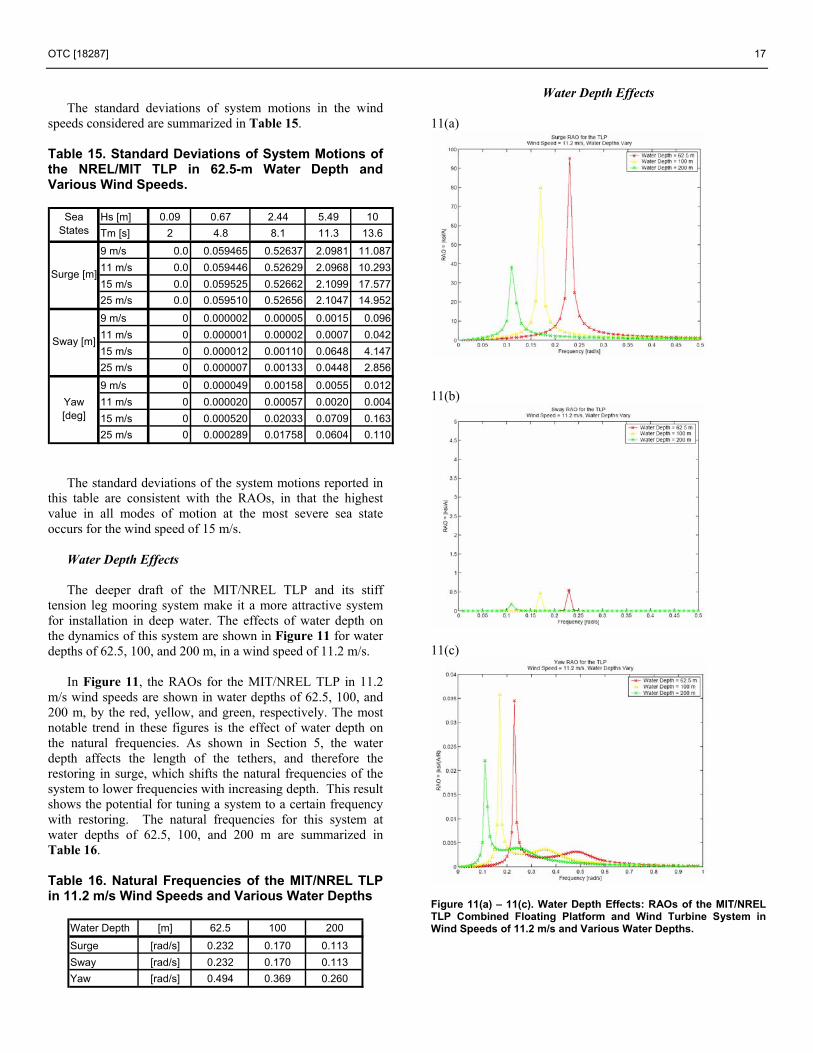
Water Depth Effects The deeper draft of the MIT/NREL TLP and its stiff
tension leg mooring system make it a more attractive system for installation in deep water. The effects of water depth on the dynamics of this system are shown in Figure 11 for water depths of 62.5, 100, and 200 m, in a wind speed of 11.2 m/s.
In Figure 11, the RAOs for the MIT/NREL TLP in 11.2 m/s wind speeds are shown in water depths of 62.5, 100, and 200 m, by the red, yellow, and green, respectively. The most notable trend in these figures is the effect of water depth on the natural frequencies. As shown in Section 5, the water depth affects the length of the tethers, and therefore the restoring in surge, which shifts the natural frequencies of the system to lower frequencies with increasing depth. This result shows the potential for tuning a system to a certain frequency with restoring. The natural frequencies for this system at water depths of 62.5, 100, and 200 m are summarized in Table 16.
Table 16. Natural Frequencies of the MIT/NREL TLP in 11.2 m/s Wind Speeds and Various Water Depths
Water Depth [m] 62.5 100 200
Surge [rad/s] 0.232 0.170 0.113Sway [rad/s] 0.232 0.170 0.113Yaw [rad/s] 0.494 0.369 0.260
Water Depth Effects 11(a)
11(b)
11(c)
Figure 11(a) – 11(c). Water Depth Effects: RAOs of the MIT/NREL TLP Combined Floating Platform and Wind Turbine System in Wind Speeds of 11.2 m/s and Various Water Depths.
18 OTC [18287]
The RAOs for the system in various water depths, shown in Figure 11 result in the standard deviations of the system motions summarized in Table 17. Table 17. Standard Deviations of the System Motions of the NREL/MIT TLP in 11.2 m/s Wind Speeds and Various Water Depths
Hs [m] 0.09 0.67 2.44 5.49 10Tm [s] 2 4.8 8.1 11.3 13.6
62.5 m 0.000 0.059 0.526 2.097 10.293100 m 0.000 0.058 0.472 1.533 3.560200 m 0.000 0.057 0.449 1.330 2.762
62.5 m 0 0.000 0.000 0.001 0.042100 m 0 0.000 0.000 0.000 0.000200 m 0 0.000 0.000 0.000 0.000
62.5 m 0 0.000 0.001 0.002 0.004100 m 0 0.000 0.000 0.002 0.004200 m 0 0.000 0.000 0.001 0.003
Sway [m]
Yaw [deg]
Sea States
Surge [m]
The RAOs and the standard deviation of system motions show that the motions decrease with increasing water depths. This can be explained by the decrease in the magnitude of the RAOs with depth. These reduced motions with increasing water depth confirm that the TLP is a good candidate for deep water deployment.
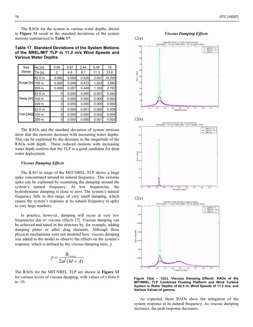
Viscous Damping Effects
The RAO in surge of the MIT/NREL TLP shows a large
spike concentrated around its natural frequency. This extreme spike can be explained by examining the damping around the system’s natural frequency. At low frequencies, the hydrodynamic damping is close to zero. The system’s natural frequency falls in this range of very small damping, which causes the system’s response at its natural frequency to spike to very large numbers.
In practice, however, damping will occur at very low
frequencies due to viscous effects [7]. Viscous damping can be achieved and tuned in the structure by, for example, adding damping plates or other drag elements. Although these physical mechanisms were not modeled here, viscous damping was added to the model to observe the effects on the system’s response, which is defined by the viscous damping ratio, γ.
*2 ( )ViscousBM A
γω
=+
The RAOs for the MIT/NREL TLP are shown in Figure 12 for various levels of viscous damping, with values of γ from 0 to .10.
Viscous Damping Effects
12(a)
12(b)
12(c)
Figure 12(a) – 12(c). Viscous Damping Effects: RAOs of the MIT/NREL TLP Combined Floating Platform and Wind Turbine System in Water Depths of 62.5 m, Wind Speeds of 11.2 m/s, and Various Values of gamma.
As expected, these RAOs show the mitigation of the
system response at its natural frequency. As viscous damping increases, the peak response decreases.

OTC [18287] 19
The natural frequencies of the system remain unaffected
by damping (see Table 13). The results of viscous damping on the standard deviations
of the system motions are summarized in Table 18. Table 18. Standard Deviation of System Motions of the NREL/MIT TLP in 62.5-m Water Depth and 11.2 m/s Wind Speed, with Various Viscous Damping Ratios.
Hs [m] 0.09 0.67 2.44 5.49 10Tm [s] 2 4.8 8.1 11.3 13.6
= 0 0.000 0.059 0.526 2.097 10.293 = .05 0.000 0.059 0.523 2.069 6.513 = .10 0.000 0.058 0.518 2.025 5.822 = 0 0.000 0.000 0.000 0.001 0.042 = .05 0.000 0.000 0.000 0.000 0.008 = .10 0.000 0.000 0.000 0.000 0.004 = 0 0.000 0.000 0.001 0.002 0.004 = .05 0.000 0.000 0.001 0.002 0.004 = .10 0.000 0.000 0.001 0.002 0.004
Yaw [deg]
Sea States
Surge [m]
Sway [m]
As suggested by the RAOs, the standard deviations of motions decrease with higher levels of viscous damping. This is especially apparent in the more extreme sea states where the peak of the wave spectrum aligns with the peak of the RAOs. This indicates the great potential for the practical tuning of the system’s response at resonance.
9. Loads and Responses in Extreme Waves The study presented in this article is based on linear theory and the use of standard simulation tools that are routinely used by the wind industry to analyze wind turbine loads and performance and the offshore industry to analyze floating structures. Within the limitations of linear wave body interaction theory (namely, moderate ambient wave slopes, small amplitudes of the system rectilinear motions, and small angular displacements that are comparable to the ambient wave slopes), the predictions of the theory are likely to offer reliable guidance for the responses of the floating wind turbine system in realistic wave environments.
The overall dynamic responses of both MIT/NREL system concepts predicted by the linear analysis are very favorable and underscore their promise for commercial applications. Yet, extreme waves of large amplitude are often present in severe storms and a robust floating wind turbine system must be designed for such conditions. This analysis is beyond the scope of the present study, but it would be carried out as outlined here.
Extreme or breaking waves may be responsible for
slamming loads on the overhangs of the SDB and TLP floaters, and may cause bottom slamming of the SDB floater when its draft is small. Moreover, the SDB floater may experience a large pitch response caused by an ambient wave
of large amplitude. This would not be the case for the TLP floater, which is constrained in pitch.
Possible ways to mitigate such extreme wave effects
would be to increase the freeboard of both floaters and consider a conically shaped superstructure with negative flare that may mitigate slamming loads. For the SDB floater, bottom slamming may be mitigated by increasing its draft.
The TLP floater may be able to absorb extreme wave-
induced responses and loads via its setdown, which occurs naturally because of its stiff tether system. Moreover, excessive setdown is unlikely because of the buoyancy effect, which acts naturally to restore the system to its mean position. So the TLP floater appears to be an attractive design for extreme wave environments. This is less obvious for the SDB floater, which is compliant in pitch and therefore exposed to extreme motions in pitch. Therefore, the SDB may be a better design for sheltered and shallower coastal waters where extreme waves are less likely. An SDB floater that is tethered to the sea floor like a TLP is possible with design attributes that may vary depending on water depth and wave environment. This study has developed the basic methodology on how such a design would be created and evaluated.
Approximate wave body interaction tools can be used to
analyze the responses of floating structures in steep ambient waves. Their predictions would need to be validated against tank tests which are quite possible for the floater concepts considered in the present study. Moreover, the responses of the wind turbine system would also need to be considered and modeled. A detailed design analysis, which accounts for turbulent winds, stochastic and extreme waves, turbine flexibility, and the action of the control and protection system, would need to be carried out in the time domain along the lines of Jonkman and Sclavounos [6]. 10. Cost Analysis A cost analysis was performed on the MIT/NREL SDB and TLP to estimate the total cost of the floating structure, mooring systems, and installation processes associated with each design. The costs estimated here do not include the wind turbine, power electronics, or transmission system.
Several assumptions were made about the construction and
installation process, and the costs of labor, materials, and equipment. These assumptions were based on quotes from manufacturers, consultants, and contractors in the marine industry, and are detailed in Table 19.
Floating wind turbine systems are intended for deployment
in a wind farm setting, consisting of many individual units. Because the MIT/NREL SDB and TLP may be deployed with the wind turbine already mounted, each unit is assumed to be produced by an assembly line style process in a shipyard and towed to its installation site for commissioning. The platforms will first be fabricated in the shipyard. Next the turbines will be installed to the platform using a crane at the shipyard. The mooring system will then be installed and the floating wind
20 OTC [18287]
turbine units will then be towed to their installation sites and attached to their mooring lines.
It is also assumed that these structures are intended for
deployment in U.S. coastal waters, and are therefore manufactured and commissioned in the United States.
The cost of steel and concrete were estimated by
considering quotes from manufacturers, and were taken to reflect unfinished steel and batch concrete produced in the United States.
The cost of mounting the wind turbine to the floating
platform was estimated for mounting the wind turbine at the shipyard and at sea. For the option of mounting the wind turbine at sea, a costly crane would be required, and with a full crew manning the process 24 hours a day, 2 installations could be accomplished in 24 hours. This option is subject to unpredictable weather windows and requires a large crew to be stationed at sea during the entire installation process. For the option of mounting the wind turbine at the shipyard, it is assumed that a crane would be on site that would charge a lifting fee per wind turbine. Once the platforms are manufactured, mounting the wind turbine at the shipyard would then be an assembly line process utilizing the crane on site. Due to the assembly line style of this process, mounting wind turbines to platforms in a shipyard is estimated to be even less expensive than mounting a wind turbine onto a foundation on land.
Anchor and mooring line costs were taken from quotes
from the offshore industry and from product manuals. Two alternative anchoring technologies were considered, the drag embedment vertical load anchor (VLA) and the suction pile. The VLA is a patented, proprietary technology, and is installed either by 1 or 2 anchor handling vehicles (AHVs) that drag the anchor into the sea bed. Once the AHV loads the anchor to its installation load, the anchor snaps into its vertical load-bearing orientation, and installation is complete. This installation technique avoids the need for subsea equipment, but can result in anchor placement that is difficult to control or predict, and necessitates thorough geotechnical data of a large footprint of the sea floor. Suction pile anchors are cylindrical caissons that become embedded into the sea floor through suction. The caissons are lowered to the sea floor, and suction is applied to a valve at the top of the caisson. A combination of suction and the exterior hydrostatic pressure drive the pile into the sea floor. This installation process requires the use of subsea pumps, and sometimes divers. The caissons, however, are easily manufactured, and avoid the retail fees associated with the VLA. A cost of $25 and $15 per kN of vertical load, or a minimum anchor cost of $50,000 and $25,000 were estimated for the VLA and the suction pile, respectively.
Two methods of anchor installation were outlined as well.
Installation Option 1 employs a barge and a tug, and Installation Option 2 requires an AHV. While Installation Option 1 has a lower cost on a daily rate, Installation Option 2 promises a lower cost per anchor. It is assumed that floating wind turbine systems will be installed in a wind farm array,
and will require enough anchor installations to make Installation Option 2 more economical.
The cost of transporting the assembled system to its
installation site, and installing it to its mooring lines was estimated assuming an installation site of 100 miles from the shipyard.
The tables and figures to follow detail these estimates and
show the total cost breakdown for each system.
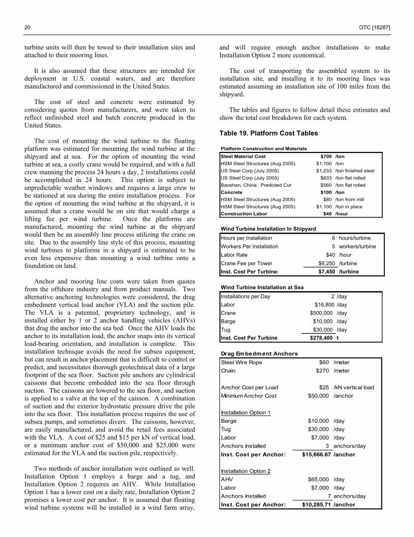
Table 19. Platform Cost Tables Platform Construction and MaterialsSteel Material Cost $700 /tonHSM Steel Structures (Aug 2005) $1,100 /tonUS Steel Corp (July 2005) $1,233 /ton finished steelUS Steel Corp (July 2005) $633 /ton flat rolledBaoshan, China: Predicted Cut $560 /ton flat rolledConcrete $100 /tonHSM Steel Structures (Aug 2005) $80 /ton from millHSM Steel Structures (Aug 2005) $1,100 /ton in placeConstruction Labor $40 /hour Wind Turbine Installation In ShipyardHours per Installation 6 hours/turbineWorkers Per Installation 5 workers/turbineLabor Rate $40 /hourCrane Fee per Tower $6,250 /turbineInst. Cost Per Turbine: $7,450 /turbine
Wind Turbine Installation at SeaInstallations per Day 2 /dayLabor $16,800 /dayCrane $500,000 /dayBarge $10,000 /dayTug $30,000 /dayInst. Cost Per Turbine $278,400 t
Drag Embedment AnchorsSteel Wire Rope $60 /meterChain $270 /meter
Anchor Cost per Load $25 /kN vertical loadMinimum Anchor Cost $50,000 /anchor
Installation Option 1Barge $10,000 /dayTug $30,000 /dayLabor $7,000 /dayAnchors Installed 3 anchors/dayInst. Cost per Anchor: $15,666.67 /anchor
Installation Option 2AHV $65,000 /dayLabor $7,000 /dayAnchors Installed 7 anchors/dayInst. Cost per Anchor: $10,285.71 /anchor
OTC [18287] 21
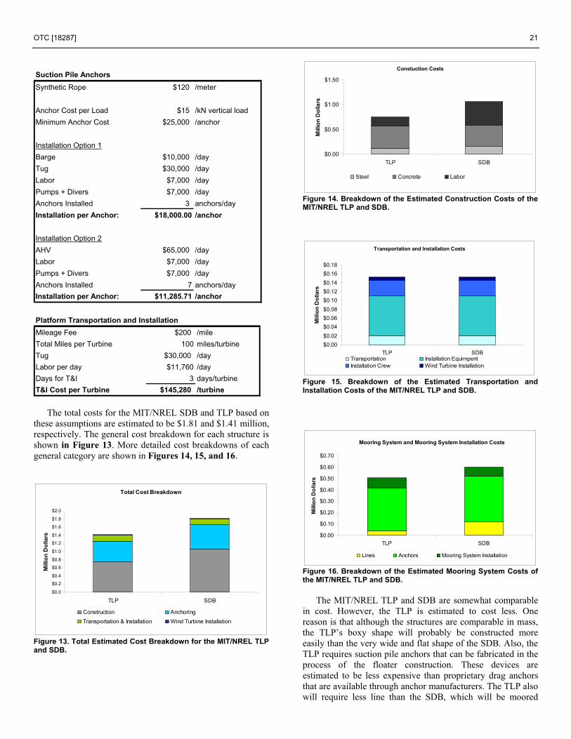
Suction Pile AnchorsSynthetic Rope $120 /meter
Anchor Cost per Load $15 /kN vertical loadMinimum Anchor Cost $25,000 /anchor
Installation Option 1Barge $10,000 /dayTug $30,000 /dayLabor $7,000 /dayPumps + Divers $7,000 /dayAnchors Installed 3 anchors/dayInstallation per Anchor: $18,000.00 /anchor
Installation Option 2AHV $65,000 /dayLabor $7,000 /dayPumps + Divers $7,000 /dayAnchors Installed 7 anchors/dayInstallation per Anchor: $11,285.71 /anchor Platform Transportation and InstallationMileage Fee $200 /mileTotal Miles per Turbine 100 miles/turbineTug $30,000 /dayLabor per day $11,760 /dayDays for T&I 3 days/turbineT&I Cost per Turbine $145,280 /turbine
The total costs for the MIT/NREL SDB and TLP based on
these assumptions are estimated to be $1.81 and $1.41 million, respectively. The general cost breakdown for each structure is shown in Figure 13. More detailed cost breakdowns of each general category are shown in Figures 14, 15, and 16.
Total Cost Breakdown
$0.0
$0.2
$0.4
$0.6
$0.8
$1.0
$1.2
$1.4
$1.6
$1.8
$2.0
TLP SDB
Mill
ion
Dol
lars
Construction AnchoringTransportation & Installation Wind Turbine Installation
Figure 13. Total Estimated Cost Breakdown for the MIT/NREL TLP and SDB.
Constuction Costs
$0.00
$0.50
$1.00
$1.50
TLP SDB
Mill
ion
Dol
lars
Steel Concrete Labor
Figure 14. Breakdown of the Estimated Construction Costs of the MIT/NREL TLP and SDB.
Transportation and Installation Costs
$0.00$0.02$0.04$0.06$0.08$0.10$0.12$0.14$0.16$0.18
TLP SDB
Mill
ion
Dol
lars
Transportation Installation EquimpentInstallation Crew Wind Turbine Installation
Figure 15. Breakdown of the Estimated Transportation and Installation Costs of the MIT/NREL TLP and SDB.
Mooring System and Mooring System Installation Costs
$0.00
$0.10
$0.20
$0.30
$0.40
$0.50
$0.60
$0.70
TLP SDB
Mill
ion
Dol
lars
Lines Anchors Mooring System Installation
Figure 16. Breakdown of the Estimated Mooring System Costs of the MIT/NREL TLP and SDB.
The MIT/NREL TLP and SDB are somewhat comparable in cost. However, the TLP is estimated to cost less. One reason is that although the structures are comparable in mass, the TLP’s boxy shape will probably be constructed more easily than the very wide and flat shape of the SDB. Also, the TLP requires suction pile anchors that can be fabricated in the process of the floater construction. These devices are estimated to be less expensive than proprietary drag anchors that are available through anchor manufacturers. The TLP also will require less line than the SDB, which will be moored

22 OTC [18287]
through a catenary system that will fill a large footprint, thus using significantly more line. 11. Conclusions A complete analysis of static and coupled dynamic analysis of floating wind turbine systems was conducted with linear theory and standard tools that are used by the wind and offshore industries.
Two floater concepts have been considered: a TLP and an SDB that may be deployed in offshore environments with water depths of 10−200 m. A critical consideration that was factored into the development of both designs is that they are statically stable in their nonmoored condition, which allows them to be assembled at a near shore facility and towed to the offshore site. The dynamic response properties of both concepts in their moored condition have been very favorable. Their responses in extreme wave conditions will be considered in a future study.
A baseline cost analysis estimates the total costs for these
structures to be $1.4−$1.8 million. These figures include the construction, labor, mooring system, and installation costs of the platform, as well as the cost of mounting the wind turbine to the platform. These figures do not include the cost of the wind turbine, power electronics, or the transmission system. These estimates offer promising figures and encourage further consideration of floating wind turbine systems. 12. Acknowledgments This study was undertaken as a collaborative effort between MIT and NREL and funded by NREL (Subcontract No. XAM-4-33200-04). This financial support is gratefully acknowledged. Also contributing to the cost analysis reported in this study are the following individuals and groups.
• Professor Rob Randal, TAMU • Jens Rasmussen, GVA Consultants • Koos Krispijn, HSM Steel Structures • Mike Lane, Poseidon • Ralph Plummer, Spectra International, Inc. • Evan Zimmerman, DelMar Systems • Roderick Ruinen, Vryhof Anchors • Nick McKenna, BP/MIT
13. References [1] Butterfield, S., Musial, W., Jonkman, J., Sclavounos, P.,
Wayman, E., “Engineering Challenges for Floating Offshore Wind Turbines,” Copenhagen Offshore Wind 2005 Conference and Expedition Proceedings, 25-28 October 2005, Copenhagen, Denmark (to be published).
[2] Eltaher, A., Rajapaksa, Y., Chang, K. “Industry Trends for Design of Anchoring Systems for Deepwater Offshore Structures,” Offshore Technology Conference, 2003.
[3] Faltinsen, O. M. Sea Loads on Ships and Offshore Structures, Cambridge, UK: Cambridge University Press, 1999.
[4] Jonkman, J. M., Buhl, M. L., FAST User Guide, Golden, CO: National Renewable Energy Laboratory, 2005.
[5] Jonkman, J, Butterfield, S., Musial, W., and Scott, G., “Definition of a 5-MW Reference Wind Turbine for Offshore System Development,” NREL/TP-500-38060, Golden, CO: National Renewable Energy Laboratory, January 2006 (to be published).
[6] Jonkman, J. M., Sclavounos, P. D., “Development of Fully Coupled Aeroelastic and Hydrodynamic Models for Offshore Wind Turbines,” Proceedings of the 44th AIAA Aerospace Sciences Meeting and Exhibit, 9-12 January 2006, Reno, NV, Washington D.C.: American Institute of Aeronautics and Astronautics, January 2006; NREL/CP-500-39066.
[7] Kim, S., Sclavounos, P. D., “Fully Coupled Response Simulations of Theme Offshore Structures in Water Depths of up to 10,000 Feet,” Proceedings of the Eleventh International Offshore and Polar Engineering Conference, 2001.
[8] Lee, K. H., Responses of Floating Wind Turbines to Wind and Wave Excitation, Master of Science Thesis, Massachusetts Institute of Technology, 2004.
[9] Lee, K. H., Sclavounos, P. D., Wayman, E. N., “Floating Wind Turbines,” Workshop on Water Waves and Floating Bodies, May 29, 2005.
[10] Musial, W., Butterfield, S., Boone, A., “Feasibility of Floating Platform Systems for Wind Turbines,” 23rd SSME Wind Energy Symposium, 2004.
[11] Newman, J. N., Marine Hydrodynamics, Cambridge, MA: The MIT Press, 1977.
[12] Sclavounos, P. D., Surface Waves and their Interaction with Floating Bodies, Lecture Notes, Massachusetts Institute of Technology, Cambridge, MA.
[13] Tong, K.C., “Technical and Economic Aspects of a Floating Offshore Wind Farm,” Journal of Wind Engineering and Industrial Aerodynamics, 1998.
[14] Vryhof Anchor Manual, Vryhof Systems, 2000. [15] WAMIT® User Guide, Cambridge, MA: WAMIT, Inc. and
MIT, 1998. [16] Withee, J. E., Fully Coupled Dynamic Analysis of a Floating
Wind Turbine System, Doctoral Thesis, Massachusetts Institute of Technology, 2004.
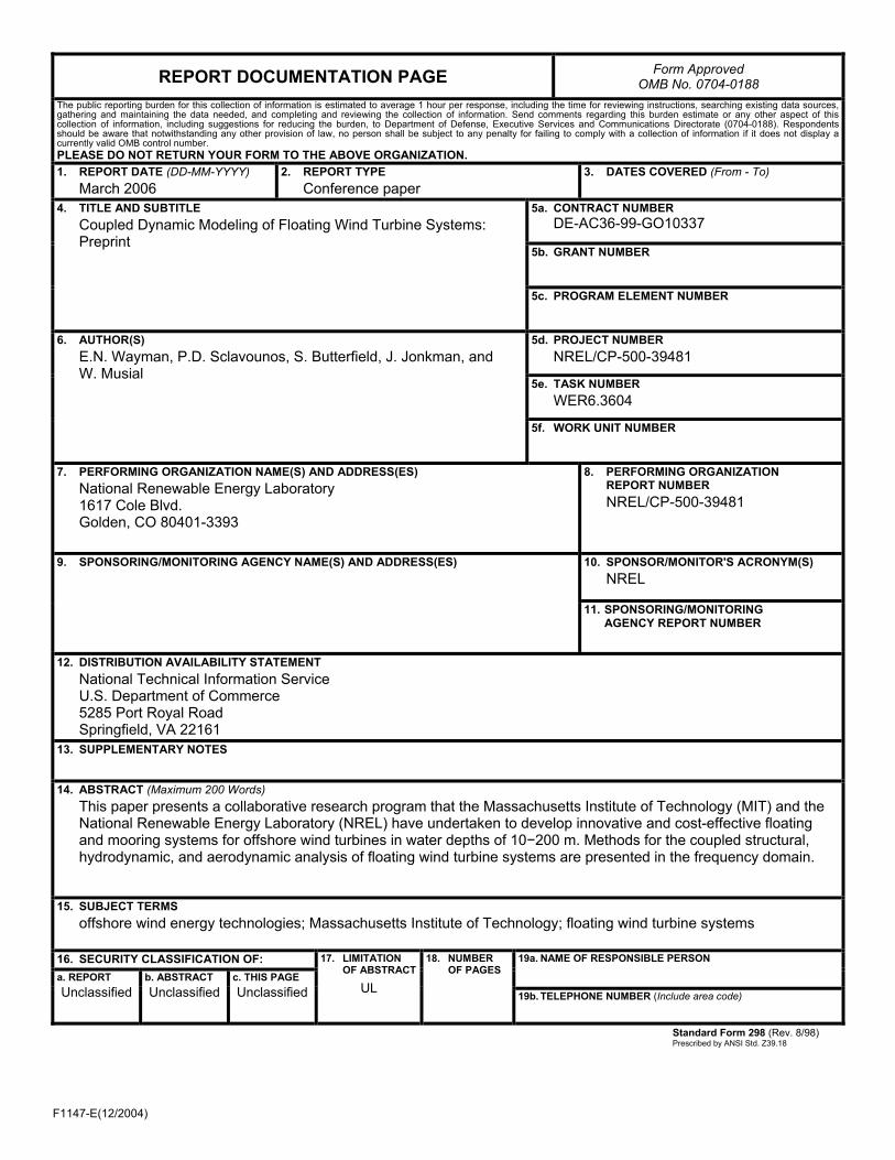
F1147-E(12/2004)
REPORT DOCUMENTATION PAGE Form Approved OMB No. 0704-0188
The public reporting burden for this collection of information is estimated to average 1 hour per response, including the time for reviewing instructions, searching existing data sources, gathering and maintaining the data needed, and completing and reviewing the collection of information. Send comments regarding this burden estimate or any other aspect of this collection of information, including suggestions for reducing the burden, to Department of Defense, Executive Services and Communications Directorate (0704-0188). Respondents should be aware that notwithstanding any other provision of law, no person shall be subject to any penalty for failing to comply with a collection of information if it does not display a currently valid OMB control number. PLEASE DO NOT RETURN YOUR FORM TO THE ABOVE ORGANIZATION. 1. REPORT DATE (DD-MM-YYYY)
March 2006 2. REPORT TYPE
Conference paper 3. DATES COVERED (From - To)
5a. CONTRACT NUMBER
DE-AC36-99-GO10337
5b. GRANT NUMBER
4. TITLE AND SUBTITLE Coupled Dynamic Modeling of Floating Wind Turbine Systems: Preprint
5c. PROGRAM ELEMENT NUMBER
5d. PROJECT NUMBER NREL/CP-500-39481
5e. TASK NUMBER WER6.3604
6. AUTHOR(S) E.N. Wayman, P.D. Sclavounos, S. Butterfield, J. Jonkman, and W. Musial
5f. WORK UNIT NUMBER
7. PERFORMING ORGANIZATION NAME(S) AND ADDRESS(ES) National Renewable Energy Laboratory 1617 Cole Blvd. Golden, CO 80401-3393
8. PERFORMING ORGANIZATION REPORT NUMBER NREL/CP-500-39481
10. SPONSOR/MONITOR'S ACRONYM(S) NREL
9. SPONSORING/MONITORING AGENCY NAME(S) AND ADDRESS(ES)
11. SPONSORING/MONITORING AGENCY REPORT NUMBER
12. DISTRIBUTION AVAILABILITY STATEMENT National Technical Information Service U.S. Department of Commerce 5285 Port Royal Road Springfield, VA 22161
13. SUPPLEMENTARY NOTES
14. ABSTRACT (Maximum 200 Words) This paper presents a collaborative research program that the Massachusetts Institute of Technology (MIT) and the National Renewable Energy Laboratory (NREL) have undertaken to develop innovative and cost-effective floating and mooring systems for offshore wind turbines in water depths of 10−200 m. Methods for the coupled structural, hydrodynamic, and aerodynamic analysis of floating wind turbine systems are presented in the frequency domain.
15. SUBJECT TERMS offshore wind energy technologies; Massachusetts Institute of Technology; floating wind turbine systems
16. SECURITY CLASSIFICATION OF: 19a. NAME OF RESPONSIBLE PERSON a. REPORT
Unclassified b. ABSTRACT Unclassified
c. THIS PAGE Unclassified
17. LIMITATION OF ABSTRACT
UL
18. NUMBER OF PAGES
19b. TELEPHONE NUMBER (Include area code)
Standard Form 298 (Rev. 8/98) Prescribed by ANSI Std. Z39.18