nrel/sr-510-39944 estimation for small modular biomass ... · chemical synthesis designs, ... with...
TRANSCRIPT

National Renewable Energy Laboratory Innovation for Our Energy Future
A national laboratory of the U.S. Department of EnergyOffice of Energy Efficiency & Renewable Energy
NREL is operated by Midwest Research Institute ● Battelle Contract No. DE-AC36-99-GO10337
Equipment Design and Cost Estimation for Small Modular Biomass Systems, Synthesis Gas Cleanup, and Oxygen Separation Equipment Task 2: Gas Cleanup Design and Cost Estimates – Black Liquor Gasification Nexant Inc. San Francisco, California
Subcontract Report NREL/SR-510-39944 May 2006

Equipment Design and Cost Estimation for Small Modular Biomass Systems, Synthesis Gas Cleanup, and Oxygen Separation Equipment Task 2: Gas Cleanup Design and Cost Estimates – Black Liquor Gasification
Nexant Inc. San Francisco, California
NREL Technical Monitor: Kelly Ibsen Prepared under Subcontract No. ACO-5-44027
Subcontract Report NREL/SR-510-39944 May 2006
National Renewable Energy Laboratory 1617 Cole Boulevard, Golden, Colorado 80401-3393 303-275-3000 • www.nrel.gov
Operated for the U.S. Department of Energy Office of Energy Efficiency and Renewable Energy by Midwest Research Institute • Battelle
Contract No. DE-AC36-99-GO10337

This publication was reproduced from the best available copy Submitted by the subcontractor and received no editorial review at NREL
NOTICE
This report was prepared as an account of work sponsored by an agency of the United States government. Neither the United States government nor any agency thereof, nor any of their employees, makes any warranty, express or implied, or assumes any legal liability or responsibility for the accuracy, completeness, or usefulness of any information, apparatus, product, or process disclosed, or represents that its use would not infringe privately owned rights. Reference herein to any specific commercial product, process, or service by trade name, trademark, manufacturer, or otherwise does not necessarily constitute or imply its endorsement, recommendation, or favoring by the United States government or any agency thereof. The views and opinions of authors expressed herein do not necessarily state or reflect those of the United States government or any agency thereof.
Available electronically at http://www.osti.gov/bridge
Available for a processing fee to U.S. Department of Energy and its contractors, in paper, from:
U.S. Department of Energy Office of Scientific and Technical Information P.O. Box 62 Oak Ridge, TN 37831-0062 phone: 865.576.8401 fax: 865.576.5728 email: mailto:[email protected]
Available for sale to the public, in paper, from: U.S. Department of Commerce National Technical Information Service 5285 Port Royal Road Springfield, VA 22161 phone: 800.553.6847 fax: 703.605.6900 email: [email protected] online ordering: http://www.ntis.gov/ordering.htm
Printed on paper containing at least 50% wastepaper, including 20% postconsumer waste

Contents
Sections Page
Executive Summary................................................................................................................ ES-1 Introduction and Methodology.................................................................................................... 1 Section 1 Process Selection Rationale................................................................................... 1-1
1.1 Introduction.................................................................................................................. 1-1 1.2 Process Description and Rationale............................................................................... 1-2
1.2.1 Sulfur Removal for Low-Temperature Design Case ........................................... 1-2 1.2.2 Sulfur Removal for High-Temperature Design Case........................................... 1-3
1.3 Discussion.................................................................................................................... 1-4 1.3.1 Technologies Not Chosen.................................................................................... 1-4
Section 2 Equipment Design and Cost Estimates ................................................................ 2-1 2.1 Introduction and Methodology .................................................................................... 2-1 2.2 Key Design Assumptions............................................................................................. 2-3 2.3 Operating Costs and Utility Requirements .................................................................. 2-3 2.4 Changing Flows, Conditions, and Compositions......................................................... 2-6
2.4.1 Flowrate Impacts.................................................................................................. 2-6 2.4.2 Composition Impacts ........................................................................................... 2-9
2.5 Follow-Up and Areas for Further Study .................................................................... 2-10 Section 3 Labor Requirements.............................................................................................. 3-1
3.1 Summary ...................................................................................................................... 3-1 3.2 Labor Requirements..................................................................................................... 3-1 3.3 Differences with Wood Gasification Cases ................................................................. 3-4
3.3.1 Size....................................................................................................................... 3-4 3.3.2 Complexity........................................................................................................... 3-5
Section 4 Sulfur Recycle Options.......................................................................................... 4-1 4.1 Introduction.................................................................................................................. 4-1 4.2 Pulping Methods .......................................................................................................... 4-1
Appendix A High-Temperature Gasifier to Power Design Case PFDs ......................... A-1 Appendix B Low-Temperature Gasifier to Power Design Case PFDs.......................... B-1 Appendix C High-Temperature Gasifier to Chemicals Design Case PFDs .................. C-1 Appendix D Low-Temperature Gasifier to Chemicals Design Case PFDs ................... D-1 Appendix E Equipment Lists ............................................................................................ E-1
Task 2: Gas Cleanup Design and Cost Estimates i Black Liquor Sulfur Removal Design and Cost Estimates United States Department of Energy/National Renewable Energy Laboratory

Contents
Tables Table Page
ES-1 Syngas Clean-Up Case Summary ..................................................................................ES-1 1-1 Syngas Compositions and Operating Parameters ............................................................ 1-1 1-2 Sulfur Specifications for Gas Cleanup............................................................................. 1-2 2-1 Black Liquor Syngas Sulfur Removal Costs (Installed) .................................................. 2-2 2-2 Catalyst and Chemicals Requirements............................................................................. 2-4 2-3 High Temperature Syngas to Power Case Utility Requirements..................................... 2-5 2-4 Low Temperature Syngas to Power Case Utility Requirements ..................................... 2-5 2-5 High Temperature Syngas to Chemicals Case Utility Requirements .............................. 2-5 2-6 Low Temperature Syngas to Chemicals Case Utility Requirements............................... 2-6 2-7 Examples of Typical Exponents for Equipment Cost Versus Capacity .......................... 2-8 3-1 Black Liquor Plant Labor Costs....................................................................................... 3-3 3-2 Complexity Differences between Black Liquor and Wood Gasification Cases .............. 3-5 4-1 Sulfur Recycle Options for Various Pulping Methods .................................................... 4-2
Task 2: Gas Cleanup Design and Cost Estimates ii Black Liquor Sulfur Removal Design and Cost Estimates United States Department of Energy/National Renewable Energy Laboratory

Executive Summary
As part of Task 2, Gas Cleanup and Cost Estimates, the team investigated the appropriate process scheme for removal of acid gases from black liquor derived syngas for use in both power and liquid fuels synthesis. Two different 3,200 metric tonne per day gasification schemes, both low-temperature/low-pressure (1100°F, 40 psi) and high-temperature/high-pressure (1800°F, 500 psi) were used for syngas production. Initial syngas conditions from each of the gasifiers was provided to the team by NREL and Princeton University. Nexant was the prime contractor and principal investigator during this task; technical assistance was provided by both GTI and Emery Energy.
The initial task was to evaluate the different technologies suitable for acid gas removal from the different syngas streams, with the end-use (power or chemicals) defining the amount of treatment required. After these preliminary investigations, process models were developed for each of the cases that incorporated equipment deemed suitable for sulfur and carbon dioxide removal. Final designs were developed that include unit sizes, energy use, capital and operating costs, and labor requirements. An analysis of the impact that syngas flowrate and composition changes have on the designs was then performed as a sensitivity to the base cases. Finally, Nexant evaluated the possible ways to reintroduce recovered sulfur back into the front-end of the pulping process.
The technologies chosen differed considerably based on the end-use of the syngas. For power applications, the target was to removal sulfur to roughly 100 ppm, while minimizing the amount of carbon dioxide removed. It was determined that COS removal beds, followed by single absorber amine systems, are suitable to meet this specification. A standard Claus and Tail Gas Treating unit is included for recovery of elemental sulfur. For the chemicals synthesis cases, a multi-column physical solvent system (Genosorb, similar in style to Selexol) was selected for deep sulfur removal and to provide suitable H2S concentration in the acid gas for feed to a standard Claus unit. Zinc oxide beds are incorporated downstream of the Genosorb units as a polishing/guard step. While amine units with zinc oxide beds were originally evaluated for the chemical synthesis designs, their inability to selectively concentrate the H2S in the acid gas stream made them unsuitable. The results of the analysis for both cases can be seen in Table ES-1 below, with information on the capital cost and utility requirements:
Table ES-1 Syngas Clean-Up Case Summary
Low-Temp to Power
High-Temp to Power
Low-Temp to Chemicals
High-Temp to Chemicals
Black Liquor Feedrate (MTPD) 3,200 3,200 3,200 3,200 Syngas Rate (Mlb/hr) 196.9 203.1 196.9 203.1 Total Installed Cost ($MM) 36.7 27.8 50.2 55.2 Power Required (MW) 1.6 1.0 5.7 5.7 Net Steam Required (Mlb/hr) 47 32 75 42
Task 2: Gas Cleanup Design and Cost Estimates ES-1 Black Liquor Sulfur Removal Design and Cost Estimates United States Department of Energy/National Renewable Energy Laboratory

Executive Summary
Table ES-1 shows how the chemical synthesis cases require significantly more capital and power during operation. The chemicals synthesis cases are more expensive than the power cases due to the need to remove CO2 with physical solvents, the inclusion of ZnO beds, and the use of a shift reactor in the high temperature case. The need for the shift reactor creates additional carbon dioxide, placing a greater load on the Genosorb system. The pressure in both chemicals cases is lower than what is typically observed in physical solvent systems, leading to higher solvent circulation requirements and cost. The use of ZnO and shift reactors requires additional heat exchangers to be added to the design, further increasing the cost. Finally, the Genosorb system requires solvent refrigeration which increases the system power load.
The syngas from the low temperature gasifier has roughly double the mass of H2S as the high temperature case, increasing the cost of the acid gas removal and Claus sections of the low temperature plants relative to the high temperature cases. This is the main reason for the cost difference in the power only cases.
Based on the pulping process used, these designs could be incorporated into a pulp and paper facility for recovery of some of the process sulfur. This is especially true of polysulfide processes, where recovered elemental sulfur can be reacted with sodium sulfide to create polysulfide chemicals suitable for pulping uses. The use of other pulping processes may limit the ability to use recovered sulfur until new technologies are developed.
Future studies should focus on the following areas to further define suitable technologies and confirm costs:
Integration of the sulfur removal section with the other parts of the gasification plant to obtain a better understanding of overall plant costs.
Alternate methods for CO2 removal in the chemicals cases. A cost comparison of different physical solvents and other technologies for acid gas removal would provide additional data to confirm the appropriate physical solvent to use in the syngas to chemicals design. Raising the system pressure would decrease the cost of the physical solvent system.
Task 2: Gas Cleanup Design and Cost Estimates ES-2 Black Liquor Sulfur Removal Design and Cost Estimates United States Department of Energy/National Renewable Energy Laboratory
Introduction and Methodology
This study provides designs and costs for sulfur removal from black liquor derived syngas for both liquid fuels synthesis and power generation. Two different syngas compositions, derived from both low (1100°F) and high (1800°F) temperature gasification conditions, were evaluated for a 3200 metric tonne per day plant. The different gasification conditions and end-uses created four distinct cases with different conditioning requirements. The goal was to provide NREL with design packages that included process flow diagrams, equipment requirements, mass and energy balances, capital and operating costs, and labor requirements for inclusion into a larger black liquor conversion study. The study also addressed how the designs would be impacted by changing flowrates and syngas compositions.
The work was divided into two main task areas. The first Subtasks (2.4.1 and 2.4.2) discussed the technologies suitable for sulfur removal for each case, along with major areas of uncertainty that would be studied in greater detail during the design. This rationale for technology selection has been updated and is shown in Section 1. Subtasks 2.4.3 through 2.4.7 consisted of equipment sizing, development of costs, and scaling analysis. This was an iterative process, for some of the technologies initially selected for use were later rejected after performing process modeling and receiving information from vendors. The final design and cost information, reflecting technologies appropriate for each case, is shown in Sections 2 and 3. While the issue of how recovered sulfur can be recycled for use in the pulping process was not quantitatively addressed, process options are discussed in Section 4.
A variety of resources were used throughout the project to produce the final designs. In gathering the initial technology data, previous team studies (especially the wood gasification cases addressed in Subtask 2.2 of this overall study), data on black liquor gasification from Dr. Eric Larson at Princeton University, vendor information, and NREL input were all used to establish the items for consideration. Vendors were especially helpful in providing data for packaged units and unique technologies, such as Ortloff Engineers (Claus sulfur recovery), Uhde/GTI (physical solvent systems), Sud-Chemie (COS beds), and Johnson Matthey (ZnO beds).
HYSYS was used for modeling the overall process. Design and performance for many of the units is based off of previous studies and vendor supplied information. Costing was performed in a similar fashion as design, with commercially available software, ICARUS, used for much of the equipment sized using HYSYS. All cost estimates use a second quarter 2005 basis. Quotes were obtained from vendors for the packaged units and unique technologies mentioned above. Industry derived cost curves were used for the acid gas removal systems and as a check on other process items. Operating costs were developed from vendor supplied information and the system energy balance. Finally, labor requirements are derived from a scale-up of a detailed study put together by Emery Energy specific to biomass gasification. Comparisons are made to the labor estimate produced for the wood gasification case in Subtask 2.2.
Task 2: Gas Cleanup Design and Cost Estimates 1 Black Liquor Sulfur Removal Design and Cost Estimates United States Department of Energy/National Renewable Energy Laboratory

Section 1 Process Selection Rationale
1.1 INTRODUCTION The initial goal for the Nexant team was to evaluate the different sulfur cleanup processes suitable for syngas produced from a 3200 metric tonne per day black liquor gasification process. Two design cases have been explored: meeting the sulfur specifications for power generation (~100 ppm) and chemicals production (~0.1 ppm). The rationale for the technology selection is discussed in this section.
The syngas compositions and sulfur cleanup requirements are listed in Tables 1-1 and 1-2 below. Table 1-1 lists the syngas compositions for the high-temperature gasification case after syngas cooling and heat recovery. For the low-temperature gasification case, the syngas composition listed is after syngas cooling and compression.
Table 1-1 Syngas Compositions and Operating Parameters1
High-Temperature Gasifier Syngas
Low-Temperature Gasifier Syngas
Gasifier Temperature 1,832°F (1000°C) 1,112°F (600°C) Gasifier Pressure 508 psia (35 bar) 39 psia (2.7 bar) Syngas Flowrate (lb/hr) 203,133 196,870 Syngas temperature to the sulfur removal unit, °F 252 200 Syngas pressure to the sulfur removal unit, psia 487 332 Compositions Mol% Mol% H2 36.30 55.68 CO 34.44 21.35 CO2 18.15 13.80 CH4 1.88 3.13 H2O 6.32 3.85 COS 0.07 0.01 H2S 1.63 2.17 NH3 0.005 - Ar 0.87 - N2 0.32 - H2:CO molar ratio 1.05 2.61
1 Information from Dr. Eric Larson, Princeton University Task 2: Gas Cleanup Design and Cost Estimates 1-1 Black Liquor Sulfur Removal Design and Cost Estimates United States Department of Energy/National Renewable Energy Laboratory

Section 1 Process Selection Rationale
Table 1-2 Sulfur Specifications for Gas Cleanup
Process Contaminants Level Source/Comment
Power Generation Sulfur 100 ppmv Typically between 100 and 200 ppm for coal gasification facilities
Methanol Synthesis Sulfur (not COS) <0.5 ppmv (<0.1 ppmv preferred)
Kung, 1992
1.2 PROCESS DESCRIPTION AND RATIONALE 1.2.1 Sulfur Removal for Low-Temperature Design Case Sulfur Removal for Power Generation The syngas exiting the low-temperature gasifier contains sulfur compounds that must be removed prior to power generation or chemicals production. For the power generation cases, the selected sulfur removal process is a COS hydrolysis reactor followed by an amine unit. The syngas, at 200°F and 337 psia, enters the COS hydrolysis reactor where COS is converted to H2S. The syngas exiting the COS hydrolysis unit is cooled to the operating temperature of the amine unit, approximately at 110°F. The amine unit is designed to selectively remove H2S to a concentration of 100 ppmv; after an analysis of possible amine solvents, it was determined that MDEA is appropriate for this application. Selective removal of H2S without CO2 removal is desirable in power applications since CO2 in the syngas increases the volumetric flow to the turbine and boosts power output.
In addition to MDEA, DGA was also evaluated as a possible solvent for the amine unit. Since DGA has the ability to remove COS along with H2S, its use would allow the elimination of the upstream COS hydrolysis unit, reducing overall capital costs. While simulations run with DGA and vendor input from Huntsman showed that DGA could successfully remove ~90% of the COS, it removes too much CO2 to be appropriate for a power application.
The acid gas from the amine system is sent to the sulfur recovery unit (SRU). The SRU is a Claus plant with a sulfur recovery capacity of approximately 100 TPD. Although this sulfur recovery rate is low for a typical Claus plant, recovery of pure sulfur is desired for recycle back into the pulping process.
Sulfur Removal for Chemicals Production For the chemicals production case, the sulfur removal requirement is assumed to be what is required for methanol synthesis. The sulfur removal unit consists of a multi-absorber physical solvent system (Clarient/Uhde’s Genosorb system, similar to that of Selexol), followed by ZnO reactor beds as a polishing step. The Genosorb unit is designed to remove the bulk of the H2S to about 1 ppmv and ~70% of the CO2. CO2 removal is necessary for methanol synthesis due to the required stoichiometric ratio of H2, CO, and CO2 :
(H2 – CO2) / (CO + CO2) = 2
Task 2: Gas Cleanup Design and Cost Estimates 1-2 Black Liquor Sulfur Removal Design and Cost Estimates United States Department of Energy/National Renewable Energy Laboratory

Section 1 Process Selection Rationale
Initial investigations into sulfur removal for chemical production focused on chemical solvents, namely DEA. Although DEA can remove sufficient amounts of both H2S and CO2, the H2S content in the resulting acid gas stream is too low for feed to a Claus SRU (a minimum concentration of 40% H2S in the acid gas effluent is desired for normal Claus operation). Multiple simulations were attempted, including different amine circulation rates and two absorbers, in an attempt to increase the H2S content. None of these efforts were successful, forcing the team to explore other options for sulfur removal.
The Genosorb process is frequently marketed in Europe as an alternative to the Selexol process. Both Genosorb and Selexol physical solvent processes are based on the use of polyethylene glycol ether solvent mixtures. The Selexol process solvent is a mixture of dimethyl ethers of polyethylene glycol, and has the formulation CH3O(CH2CH2O)nCH3 where n is between 3 and 9. There are other process suppliers using solvents similar to the Selexol process, such as Clariant GmbH of Germany, which offers a family of dialkyl ethers of polyethylene glycol. The Clariant solvents, under the Genosorb name, include dimethyl and dibutyl ethers of polyethylene glycols.
Treatment in the Genosorb unit removes the H2S and COS content to roughly 1 ppm. Following the Genosorb unit, the sweet syngas enters the ZnO reactor where residual COS and H2S are removed at 750°F. The ZnO reactor is used as a polishing step to reduce the sulfur concentration to < 0.1 ppmv.
1.2.2 Sulfur Removal for High-Temperature Design Case Sulfur Removal for Power Generation For the power generation case, the sulfur removal process for the syngas from the high-temperature gasifier is similar to that of the syngas from the low-temperature gasifier. The sulfur removal unit consists of a COS hydrolysis reactor followed by an MDEA amine unit. The syngas enters the COS hydrolysis reactor at 252°F and 487 psia. Similar to the low-temperature design case, DGA was also evaluated as a possible solvent. As with the low-temperature case, DGA removes too much CO2 than what is appropriate for use in power generation.
Sulfur Removal for Chemicals Production For the chemicals production case, the sulfur removal process is also similar to that of the low-temperature gasifier case, with the exception of the shift reaction step prior to the Genosorb unit. The syngas exiting the high-temperature gasifier has a H2/CO ratio of 1.05; thus, a portion of the syngas is sent to the shift reactor to adjust the H2/CO ratio. The shifted syngas is mixed with the unshifted portion, then is cooled before entering the Genosorb unit. The configuration of the Genosorb unit is similar to that of the low-temperature syngas case. A greater amount of CO2 removal is required in this case due to the CO2 produced in the shift reactor. The sweet syngas exiting the amine unit then enters the ZnO reactor where the residual COS and H2S compounds are removed to meet the sulfur requirement of < 0.1 ppmv. As in the low temperature case, a chemical solvent system (amine) could not be configured to remove the necessary acid gases and have an H2S concentration high enough for feed to a Claus SRU.
Task 2: Gas Cleanup Design and Cost Estimates 1-3 Black Liquor Sulfur Removal Design and Cost Estimates United States Department of Energy/National Renewable Energy Laboratory

Section 1 Process Selection Rationale
1.3 DISCUSSION 1.3.1 Technologies Not Chosen Physical solvent systems such as Selexol and Rectisol were considered but not originally selected for this process. Only when it was determined that an amine system could not effectively concentrate the H2S at a high enough level for feed to a Claus SRU was a physical solvent system selected. Generally, physical solvents are considered when there is high system pressure (> 700 psi), or high acid gas partial pressure (> 50 psi). The syngas in this study has adequate acid gas partial pressure to consider physical solvent systems; however, a chemical solvent system (amine) was originally chosen instead on the basis of comparable sulfur removal capability and cost. The relatively low syngas pressure available in each case decreases the physical solvent removal efficiency and increases solvent circulation requirements. This leads to higher overall capital and operating costs.
A Rectisol system can remove virtually all the acid gas components such as H2S, CO2, COS, HCN, and mercaptans to the level required for chemicals production without the need for separate COS hydrolysis and ZnO reactor units. However, the capital investment for a Rectisol system can be significant because of the complexity, power requirements, and use of stainless steel in parts of the design. Since the syngas in this study contains only COS and H2S, the configurations established in both the power and chemicals designs should be sufficient to meet the sulfur removal requirements.
Task 2: Gas Cleanup Design and Cost Estimates 1-4 Black Liquor Sulfur Removal Design and Cost Estimates United States Department of Energy/National Renewable Energy Laboratory

Section 2 Equipment Design and Cost Estimates
2.1 INTRODUCTION AND METHODOLOGY After deciding on the appropriate technology for sulfur removal and recovery, the next step was to size process equipment for sulfur removal from black liquor derived syngas, and obtain cost estimates for individual pieces of equipment. Design and cost estimates were obtained using three major sources:
HYSYS and ICARUS were used to obtain design and cost estimates for generic equipment such as vessels, pumps, compressors, and heat exchangers. The design basis was agreed upon after the submission of the original process selection deliverable (Subtasks 2.4.1 and 2.4.2). Further refinement was made after vendor input and analysis of the process model results.
Vendor quotes were obtained for unique and specialized equipment such as ZnO catalyst/reactors, Claus sulfur recovery, and all catalysts. Performance information for the physical solvent system, Genosorb, was obtained from Uhde. Cost for the system was estimated from Uhde supplied information, previous physical solvent studies, and industry developed cost estimates for amines versus physical solvents for IGCC applications.
The performance and energy requirements for the amine units were estimated using commercially available software that is specific for amine unit modeling (ProTreat and HYSYS). In addition, input was provided by vendors for estimating COS removal from the amine systems and for assistance in simulation development. Once performance specifics were obtained, an industry developed cost curve was used for estimating installed cost.
A complete set of PFDs can be seen in Appendix A through D. The design and cost estimates for the high-pressure and low-pressure cases are presented in the Equipment List, which can be seen in Appendix E. The Equipment List groups process equipment by the following categories: reactors, cyclones, vessels, heat exchangers, compressors, pumps, turbines, and packaged units (the amine and sulfur recovery units). Shown in the Equipment List are the following items:
Unit size and weight
Design duty (exchangers)
Design temperature and pressure
Power usage
Materials of construction
Price (uninstalled) on both a Q2 2004 and Q2 2005 basis
Source for cost estimate
Comments and notes
Task 2: Gas Cleanup Design and Cost Estimates 2-1 Black Liquor Sulfur Removal Design and Cost Estimates United States Department of Energy/National Renewable Energy Laboratory

Section 2 Equipment Design and Cost Estimates
An installation factor of 2.57 was applied to the equipment cost to arrive at the total installed cost. The installation factor was derived based upon previous experience and Bechtel estimates. The total installed cost for each of the cases can be seen in Table 2-1.
Table 2-1 Black Liquor Syngas Sulfur Removal Costs (Installed)
Case Capital Cost ($MM) High–Temperature Gasifier to Power 27.8
Low-Temperature Gasifier to Power 36.7
High-Temperature Gasifier to Chemicals 55.2
Low-Temperature Gasifier to Chemicals 50.2
As can be seen in the equipment list (Appendix E), a major source of plant cost is due to the Claus sulfur recovery and Tail Gas Treating units. The cost of these units represents 60 to 70% of the overall plant costs in both power cases. The designs represent a standard Claus and Tail Gas Recovery system; however, the sulfur recovery configuration that is used in a black liquor gasification plant may vary based on the pulping process and technology choice for sulfur recovery. A more detailed explanation of the sulfur recycle options is presented in Section 4.
The chemicals synthesis cases are more expensive than the power cases due to the need to remove CO2, the inclusion of ZnO beds, and the use of a shift reactor in the high temperature case. The use of ZnO and shift reactors also requires additional heat exchangers to be added to the design, further increasing the cost. In addition, the chemicals cases required the use of more expensive physical solvents for sulfur and CO2 removal. Although COS beds were no longer necessary due to the ability of the Genosorb system to adequately remove COS, this reduction in cost did not offset the overall expense of the Genosorb unit. Lower solvent temperatures, inclusion of an additional stripping column, higher solvent flow rates, and relatively low system pressure for a physical solvent system all increases the cost of the physical solvent acid gas removal unit when compared to the amine system used in the power cases.
The high-temperature to chemicals case is more expensive than the low-temperature case due to the greater acid gas removal requirement. The shift reactor in the high-temperature case significantly increases the CO2 content, which, in general, increases the cost of the acid gas removal system. However, the lower pressure of the low-temperature system raises the removal cost on a dollar/ton basis due to higher solvent circulation requirements. Future studies should look at increasing system pressure to lower the physical solvent system cost.
The syngas from the low temperature gasifier has roughly double the mass of H2S as the high temperature cases. This increase in sulfur content not only increases the cost of the acid gas removal unit, but also significantly increases the cost of the Claus and Tail Gas Treating sections of the plant. The higher sulfur content increases the overall cost in the low-temperature cases by ~$8MM due to the increased cost of the Claus and Tail Gas Treating units. Task 2: Gas Cleanup Design and Cost Estimates 2-2 Black Liquor Sulfur Removal Design and Cost Estimates United States Department of Energy/National Renewable Energy Laboratory

Section 2 Equipment Design and Cost Estimates
2.2 KEY DESIGN ASSUMPTIONS A complete description of the process and rationale for choosing the technologies in this deliverable can be seen in Section 1. Additional design specific assumptions are outlined below.
Amine System: For the power cases, an amine needed to be used that was selective for H2S removal and that minimized CO2 removal. MDEA is appropriate and relatively cost effective in this service. The simulations performed with MDEA show that a single absorber system can work effectively, provided the amine circulation rate and column size are large enough.
Genosorb: A multi-column process was determined to be appropriate for both removing the necessary acid gas and concentrating the H2S adequately for feed to the Claus unit. The system consists of separate H2S and CO2 absorbers in order to remove the appropriate amount of acid gases specified in the design basis. This design is also necessary for flashing off CO2 captured in the H2S absorber. Multiple stages of solvent flash may be required for solvent regeneration. In addition, a CO2 enrichment column may be necessary in certain instances, such as the low temperature case, to pre-load the solvent to prevent too much CO2 removal from the syngas stream. A general multi-column process flow is shown in the PFD section of this report.
Heat Integration: Detailed heat integration was not practical for this design, since sulfur treating is only a small portion of a large black liquor gasification facility. However, areas have been identified in the PFDs where heat can be recovered via steam generation.
COS Removal Beds: In both power cases, COS hydrolysis beds were required to remove sufficient COS from the inlet syngas stream. Two different types of COS removal catalysts are used. Based on vendor recommendations, a platinum based catalyst has been selected for the high temperature gasification cases, while a chromium catalyst is used in the low temperature cases. Platinum catalysts are best suited for high pressure and streams that contain contaminants such as ammonia.
Sulfur Recovery: Per the scope agreed upon with NREL, a cost has been estimated for sulfur recovery and tail gas treating, with a generic PFD included with each design. The cost estimate is derived from previous vendor quotes for a Claus and Tail Gas Treating unit, scaled to meet the sulfur design requirements. The cost estimate has been confirmed with other literature sources. The actual configuration for sulfur recovery and reuse in the pulping process may vary.
2.3 OPERATING COSTS AND UTILITY REQUIREMENTS Operating costs and utility requirements can be seen in Tables 2-2 through 2-6. The main sources of costs are catalysts for the ZnO, shift, and COS beds, and steam/power for the acid gas removal and sulfur recovery units. With the exception of the platinum catalyst required in the high temperature power case, catalyst costs are relatively low. Power and steam needs for the acid gas removal and recovery units make up the majority of the operating costs. The physical solvent system requires significantly more power to operate than the amine unit due to the chiller required to maintain low solvent temperatures. This power requirement greatly raises the operating cost of the chemicals cases when compared to the power-only designs.
Task 2: Gas Cleanup Design and Cost Estimates 2-3 Black Liquor Sulfur Removal Design and Cost Estimates United States Department of Energy/National Renewable Energy Laboratory

Section 2 Equipment Design and Cost Estimates
Nexant has not made assumptions for the yearly operating cost at this time; this cost could vary considerably based on the assumptions made for plant performance and for steam, chemicals, and power costs. For example, the overall gasification plant may have excess power and steam that can be used by the sulfur treating units at low cost. Until this section of the plant is incorporated into a complete black liquor gasification unit, it is not possible to estimate the overall operating costs.
Table 2-2 Catalyst and Chemicals Requirements
Variable Amount Required Cost Notes COS
Removal Catalyst
Low-Temperature to Power Case: 2470 cubic feet
High-Temperature to Power Case: 2400 cubic feet
Price:
LT to Power: $575/cubic foot (Cr based)
HT to Power: $1587/cubic foot (Pt based)
Information provided by Sud-Chemie. Initial fill, then replaced every 5 years. HT case process conditions require the more robust catalyst.
ZnO Catalyst
Low-Temperature to Chemicals Case: 823 cubic feet
High-Temperature to Chemicals Case: 818 cubic feet
Price: $355/cubic foot (Johnson Matthey).
Initial fill then replaced every year. Catalyst inventory based on H2S removal capacity from 2 ppmv to 0.1 ppmv.
Sour Shift Catalyst
High-Temperature to Chemicals Case:
150 cubic feet
Price: $575/cubic foot
(Sud-Chemie)
Initial fill then replaced every one to two years.
Acid Gas Removal
Chemicals
Low-Temperature to Power Case: 337,200 lb/hr lean MDEA
High-Temperature to Power Case: 297,500 lb/hr lean MDEA
Low-Temperature to Chemicals Case:
1,160,000 lb/hr lean Genosorb
High-Temperature to Chemicals Case:
668,000 lb/hr lean Genosorb
Price:
MDEA = ~$0.50/lb
Genosorb = ~$1.30/lb
Make-up requirements may vary. Chemical cost may vary.
Task 2: Gas Cleanup Design and Cost Estimates 2-4 Black Liquor Sulfur Removal Design and Cost Estimates United States Department of Energy/National Renewable Energy Laboratory

Section 2 Equipment Design and Cost Estimates
Table 2-3 High Temperature Syngas To Power Case Utility Requirements
Norm. Max (3). KW 385
psig 35 psig 5 psig Cond. Proc. C.W. circ.
(2). Water MMBtu/hr (LHV)
H-100 Syngas Cooler/Steam Generator (7.0)H-101 Amine Precooler 2,009 20.1H-103 Lean Solvent Cooler 1,674 16.8H-104 Amine Stripper Reboiler 39.9H-105 Acid Gas Condenser 1,672 16.7P-101 Lean Solvent Pump 230 172A-120 Claus Plant 1,111 829 3.5 (5.4) (21) 29.7
TOTAL 1,341 1,000 4 35 (7) (21) 5,356 54 30
NOTES: 1. All Figures shown above represent normal utility usage requirements except: () indicates normal utility generated
* indicates intermittent usage or make, not included in totals2. CWS temperature is 80 F and CWR temperature is 100 F. Makeup water to cooling tower is not shown3. Utility consumption for max. load conditions is not shown.
Fuel Gas
Item Name
Cooling MMBTU/HRWater, GPM
Item No
Steam M Pounds per Hour
Elect. PowerLoad BHP
Table 2-4 Low Temperature Syngas To Power Case Utility Requirements
Norm. Max (3). KW 385
psig 35 psig 5 psig Cond. Proc. C.W. circ.
(2). Water MMBtu/hr (LHV)
H-100 Syngas Cooler/Steam Generator (8.6)H-101 Amine Precooler 2,080 20.8H-103 Lean Solvent Cooler 2,269 22.7H-104 Amine Stripper Reboiler 58.9 (59)H-105 Acid Gas Condenser 2,967 29.7P-101 Lean Solvent Pump 200 149A-120 Claus Plant 1,908 1423 6.0 (9.2) (36) 50.9
TOTAL 2,108 1,572 6 50 (9) (95) 7,316 73 51
NOTES: 1. All Figures shown above represent normal utility usage requirements except: () indicates normal utility generated
* indicates intermittent usage or make, not included in totals2. CWS temperature is 80 F and CWR temperature is 100 F. Makeup water to cooling tower is not shown3. Utility consumption for max. load conditions is not shown.
Steam M Pounds per Hour Water, GPM Cooling
MMBTU/HR Fuel Gas
Item No Item Name
Load BHP Elect. Power
Table 2-5 High Temperature Syngas To Chemicals Case Utility Requirements
Norm. Max (3). KW 485
psig385 psig
35 to 80
psig
5 psig Cond. Proc. C.W. circ.
(2). Water MMBtu/hr (LHV) MMSCFD
H-110 LT Shift Cooler/ LP Steam Generator (78.0)H-111 Syngas Cooler/ LP Steam Generator 15 11 (31.1)H-112 Solvent Precooler 3,095 31.0
Genosorb Unit 6,568 4,900 29.0 1,809 18.1H-118 ZnO Beds Preheater 29.9R-110 LT Shift Reactor 93.7A-120 Claus Plant 1,117 833 3.5 (5.4) (21) 29.8
TOTAL 7,700 5,744 94 4 (25) (31) (21) 4,904 49
NOTES: 1. All Figures shown above represent normal utility usage requirements except: () indicates normal utility generated
* indicates intermittent usage or make, not included in totals2. CWS temperature is 80 F and CWR temperature is 100 F. Makeup water to cooling tower is not shown3. Utility consumption for max. load conditions is not shown.
Combustion Air
Steam M Pounds per Hour Water, GPM Cooling
MMBTU/HR Fuel Gas
Item No Item Name
Load BHP Elect. Power
Task 2: Gas Cleanup Design and Cost Estimates 2-5 Black Liquor Sulfur Removal Design and Cost Estimates United States Department of Energy/National Renewable Energy Laboratory

Section 2 Equipment Design and Cost Estimates
Table 2-6 Low Temperature Syngas To Chemicals Case Utility Requirements
Norm. Max (3). KW 385
psig
35 or 80
psig
5 psig Cond. Proc. C.W. circ.
(2). Water MMBtu/hr (LHV)
H-100 Syngas Cooler/Steam Generator (8.6)H-111 Solvent Precooler 1,558 15.6H-117 ZnO Beds Preheater 45.0
Genosorb Unit 5764 4300 42.6 2,683 26.9A-120 Claus Plant 1,915 1429 6.1 (9.2) (36) 51.1
TOTAL 7,679 5,729 6 78 (9) (36) 4,242 42
NOTES: 1. All Figures shown above represent normal utility usage requirements except: () indicates normal utility generated
* indicates intermittent usage or make, not included in totals2. CWS temperature is 80 F and CWR temperature is 100 F. Makeup water to cooling tower is not shown3. Utility consumption for max. load conditions is not shown.
Steam M Pounds per Hour Water, GPM Cooling
MMBTU/HR Fuel Gas
Item No Item Name
Load BHP Elect. Power
A few differences exist in the utility requirements between the high and low temperature cases, as well as the power and chemicals cases. In general, the H2S yield out of the low-temperature gasifier is higher, leading to an increased load on the acid gas removal and sulfur recovery units. A greater net amount of power and steam is therefore necessary in the low temperature cases. The need to remove CO2 in the chemicals cases changes the type of solvent used, leading to a significantly greater power load. Solvent chilling requirements increase both the power and cooling water supply required in the chemicals cases.
2.4 CHANGING FLOWS, CONDITIONS, AND COMPOSITIONS As was presented in the wood gasification cases2, an analysis was performed to estimate the impact that changes in flowrate and composition would have on the black liquor sulfur removal designs. Information for all four design cases are outlined below; the scaling factors appropriate for each piece of equipment are listed in Table 2-7.
2.4.1 Flowrate Impacts In general, the limits on process equipment sizes are usually the result of manufacturing guidelines, transportation limits, and maintenance restrictions. An analysis of how the designs would change if the throughput was increased by 50% was performed. The effects of this change are discussed below with respect to all four black liquor gasification cases. A discussion of changes due to lower flows (i.e., a minus 50% change in flow) is not included. Designs of this nature would only make the plant equipment smaller and piping simpler (fewer parallel units).
2 Nexant, “Task 2 Final Report, Gas Cleanup Design and Cost Estimates: Wood Feedstock”, as part of Subcontract ACO-5-44027,
December 2005 Task 2: Gas Cleanup Design and Cost Estimates 2-6 Black Liquor Sulfur Removal Design and Cost Estimates United States Department of Energy/National Renewable Energy Laboratory
Section 2 Equipment Design and Cost Estimates
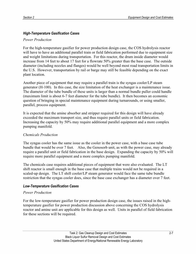
High-Temperature Gasification Cases Power Production
For the high-temperature gasifier for power production design case, the COS hydrolysis reactor will have to have an additional parallel train or field fabrication performed due to equipment size and weight limitations during transportation. For this reactor, the drum inside diameter would increase from 14 feet to about 17 feet for a flowrate 50% greater than the base case. The outside diameter (including nozzles and flanges) would be well beyond most road transportation limits in the U.S. However, transportation by rail or barge may still be feasible depending on the exact plant location.
Another piece of equipment that may require a parallel train is the syngas cooler/LP steam generator (H-100). In this case, the size limitation of the heat exchanger is a maintenance issue. The diameter of the tube bundle of these units is larger than a normal bundle puller could handle (maximum limit is about 6-7 feet diameter for the tube bundle). It then becomes an economic question of bringing in special maintenance equipment during turnarounds, or using smaller, parallel, process equipment.
It is expected that the amine absorber and stripper required for this design will have already exceeded the maximum transport size, and thus require parallel units or field fabrication. Increasing the capacity by 50% may require additional parallel equipment and a more complex pumping manifold.
Chemicals Production
The syngas cooler has the same issue as the cooler in the power case, with a base case tube bundle that would be over 7 feet. Also, the Genosorb unit, as with the power case, may already require a parallel unit or field fabrication in the base design. Expanding the capacity by 50% will require more parallel equipment and a more complex pumping manifold.
The chemicals case requires additional pieces of equipment that were also evaluated. The LT shift reactor is small enough in the base case that multiple trains would not be required in a scaled-up design. The LT shift cooler/LP steam generator would face the same tube bundle restriction that the syngas cooler does, since the base case exchanger has a diameter over 7 feet.
Low-Temperature Gasification Cases Power Production
For the low-temperature gasifier for power production design case, the issues raised in the high-temperature gasifier for power production discussion above concerning the COS hydrolysis reactor and amine unit are applicable for this design as well. Units in parallel of field fabrication for these sections will be required.
Task 2: Gas Cleanup Design and Cost Estimates 2-7 Black Liquor Sulfur Removal Design and Cost Estimates United States Department of Energy/National Renewable Energy Laboratory

Section 2 Equipment Design and Cost Estimates
Chemicals Production
For the chemicals production case, a larger ZnO bed preheater would exceed the general maintenance limits for pulling the tube bundle, and may require a parallel unit. An analysis will need to be made to determine if a parallel bed is worth the additional investment. And as with the high-temperature to chemicals case, it is likely that the Genosorb unit would require a parallel unit or field fabrication.
General Information Other considerations must be made to take into account the impact that an increase in flowrate will have on the overall plant. A plant that is 50% larger will require more plot area due not only to the larger equipment and storage requirements, but due to offsite considerations. The utility requirements will need to be scaled accordingly. In addition, the flare will have to be designed for a load that is 50% larger. This will require either a taller flare or moving the flare further away from operational units.
Estimating the Capital Investment Cost In most cases the capital cost for a capacity increase or decrease of 50% can be estimated using exponential methods. That is, the new capital cost can be estimated by using capacity ratio exponents based on published correlations and the following formula:
C2 = C1 (q2/q1)n
where C stands for cost, q for flowrate, and where the value of the exponent n depends on the type of equipment. In reviewing the literature for the various exponents, some discrepancies in published factors are apparent due to variation in definition, scope and size. Technology has also advanced over time, making it less expensive to produce larger machinery now than in years past. In addition, new regulations dictate expenditures for environmental control and safety not included in earlier equipment. In the table that follows, the most recent literature information is listed. Traditionally, when a specific value is not known, an exponent value of 0.6 is often used for equipment and a value of 0.7 for chemical process plants (usually expressed in terms of annual production capacity). Table 2-7 gives typical values of n for most of the equipment included in these designs.
Task 2: Gas Cleanup Design and Cost Estimates 2-8 Black Liquor Sulfur Removal Design and Cost Estimates United States Department of Energy/National Renewable Energy Laboratory

Section 2 Equipment Design and Cost Estimates
Table 2-7 Examples of Typical Exponents for Equipment Cost Versus Capacity3,4,5,6,7
Equipment Size Range Units Exponent** Reactor – fixed beds N/A 0.65-0.70 Column (including internals) 300-30,000 Feed rate, million lb/yr 0.62 Cyclone 20-8,000 Cubic feet/m 0.64 Vessel – vertical 100-20,000 US gallons 0.30 Vessel – horizontal 100-80,000 US gallons 0.62 Heat exchanger (S&T) 20-20,000 Square feet 0.59
Equipment Size Range Units Exponent** Venturi scrubber N/A 0.60 Compressor – centrifugal* 200-30,000 hp 0.62 Blower* 0.5 - 150 Thousand standard cubic feet per minute 0.60 Pump* 0.5-40
40-400 hp 0.30
0.67 Turbine Pressure discharge Vacuum discharge
20-5,000
200-8,000
hp 0.81
MOTOR 10-25 25-200
hp 0.56 0.77
Package unit N/A 0.75 Other N/A 0.6 – 0.7 * excluding driver ** this estimating method gives only the purchase price of the equipment; additional installation cost for labor, foundations and construction
expenses will make the final cost higher.
2.4.2 Composition Impacts The designs presented here are most sensitive to changes in CO and COS. It does not appear that changes significant enough in CO2, H2S, or methane concentrations could occur that would change the designs significantly. The expected rates of fluctuation in these components could be handled by the current designs.
Increasing the CO concentration will have a significant influence on the COS hydrolysis reactor for the low-temperature to power case. At a higher CO concentration, a different catalyst (platinum on alumina) would be recommended by the vendor to provide a greater efficiency and appropriate performance. The platinum based catalyst will be more expensive, but a smaller reactor will be necessary due to the higher space velocity necessary. Changes in the H2/CO ratio
3 Perry, Robert H., and Green Don W., Perry’s Chemical Engineers’ Handbook, 7th edition, page 9-69. 4 Walas, Stanley M., “Chemical Process Equipment – Selection and Design,” Butterworths, page 665 5 Blank, L. T. and A. J. Tarquin, “Engineering Economy,” McGraw-Hill 6 Peters, Max S. and Timmerhaus, Klaus D., “Plant Design and Economics for Chemical Engineers,” McGraw-Hill, page 170 7 Remer, Donald S. and Chai, Lawrence H., “Design Cost Factors for Scaling-up Engineering Equipment,” Chemical Engineering Progress,
August 1990, pp 77-82 Task 2: Gas Cleanup Design and Cost Estimates 2-9 Black Liquor Sulfur Removal Design and Cost Estimates United States Department of Energy/National Renewable Energy Laboratory

Section 2 Equipment Design and Cost Estimates
could also impact the chemicals cases, and may require different conditions to assure the appropriate ratio for synthesis is maintained.
An increase in the COS concentration could be significant since the COS reactors are already at the limit for most forms of transport (14 feet). An elevated amount of COS entering the reactor would require either more frequent catalyst changeouts, a change in the way the reactor is fabricated, or a parallel train.
2.5 FOLLOW-UP AND AREAS FOR FURTHER STUDY The analysis performed in this section of the project sets the base case for the sulfur removal section of four different black liquor gasification designs. After in-depth analysis of these cases, the team has identified a number of areas for further study:
The original vendor quotes obtained for COS removal used a platinum catalyst for both power designs. Only through in-depth discussion with the vendor was it determined that a chromium catalyst could be substituted for some process conditions. A greater investigation of the assumed process conditions and discussions with other vendors will help to confirm if the more expensive platinum catalyst is necessary.
Integration of the sulfur removal section with the other parts of the gasification plant to get a better picture of overall plant costs.
− An analysis should also be performed for how the result of this analysis fits with previous black liquor gasification studies, such as the Larson papers8. Previous studies have spent little time on this topic; integrating the detailed results from this study will provide more insight and better accuracy for the actual facility costs.
Alternate methods for CO2 removal in the chemicals cases. A cost comparison of different physical solvents and other technologies for acid gas removal would provide additional data to confirm the appropriate physical solvent to use in the syngas to chemicals design. Use of amine has already been ruled out due to the inability to concentrate H2S in the feed stream to the Claus unit.
Appropriate assumptions for operating costs, including availability, catalyst life in each major reactor, and a determination of if steam and power could be exported from elsewhere in the gasification plant.
An investigation into the ability to raise the syngas pressure in the chemicals cases to lower the cost of the acid gas removal system. While raising system pressure will either require different gasification design specifications or downstream compression, these changes may be justified based on the decrease in unit costs of the physical solvent acid gas removal system.
8 Larson E.D., S. Consonni, and R.E. Katofsky (2003). “A Cost-Benefit Assessment of Biomass Gasification Power Generation in the Pulp
and Paper Industry,” Princeton University, October 3, Page 96. Task 2: Gas Cleanup Design and Cost Estimates 2-10 Black Liquor Sulfur Removal Design and Cost Estimates United States Department of Energy/National Renewable Energy Laboratory

Section 3 Labor Requirements
3.1 SUMMARY The work completed in the previously referenced wood gasification designs acts as a base case to estimate the labor requirements for the four black liquor derived syngas cases. Because this design task focused on only a small portion of the overall black liquor conversion facility, a number of assumptions had to be made for the rest of the plant. Differences with the wood gasification cases were identified and will be highlighted below.
The two major items investigated relative to the wood gasification cases were the plant size and the level of complexity. For labor estimating purposes, the black liquor plant size is considered roughly similar to the wood gasification cases. While a greater amount of mass is being fed to the gasifier (3200 MTPD of black liquor, versus 2000 MTPD of wood), the amount of syngas entering the sulfur removal block is actually lower (~200 Mlb/hr versus 227 to 272 Mlb/hr). Based on these numbers, the plant size for labor purposes is considered the same.
All the black liquor designs are also estimated to have roughly the same complexity as the wood gasification cases. While the black liquor gasification plants have additional sulfur treatment requirements (COS beds, Claus units, and two absorber acid gas treatment units for the chemicals cases), some units that exist in the wood gasification cases, such as feedstock handling and the LO-CAT unit, are no longer required. In addition, the cases producing power would require a gas turbine and HRSG, but would no longer need units specific to chemicals synthesis, such as additional syngas compressors, reactors, and certain heat exchange equipment. For these reasons, the complexity between the power and chemicals cases is also considered similar.
In summary, the labor estimate for the chemicals cases is estimated to be the same as for the wood gasification cases, $2,539,720/year. For the power cases, it is not expected that a dedicated on-site laboratory would be required. Eliminating the laboratory manager and technician needs will cut the labor requirements by $220,800/year, to $2,318,920/year total labor costs.
3.2 LABOR REQUIREMENTS The following labor categories and positions will be required for the 3200 MTPD black liquor gasification plant. It is assumed that this facility is connected to, but independent from, the pulp and paper plant. Having a dedicated feed source to the gasification plant will eliminate the need for feedstock handling and storage facilities. If the plant is independent, a different management team and overhead rate is necessary than what may be used in the pulping plant. If both the pulping and gasification facility was owned and operated by the same entity, it is possible that management, overhead, and technical labor costs could be reduced. Since black liquor gasification is not a widely accepted commercial technology that will likely be owned and operated by a group distinct from the existing pulp and paper facility, this synergy is not assumed at this time. Plant optimization studies should keep this potential cost reduction in mind.
Task 2: Gas Cleanup Design and Cost Estimates 3-1 Black Liquor Sulfur Removal Design and Cost Estimates United States Department of Energy/National Renewable Energy Laboratory

Section 3 Labor Requirements
The information below was largely presented in the wood gasification final report. Slight modifications have been made for the black liquor cases.
General Plant Manager: Responsible for all personnel and plant decisions, including new employee hiring, operator training, fuel contracts, maintenance contracts, general equipment purchases, external communications, and operating schedules. Engineering degree required, with 10+ years of chemical plant operating experience. Salary of $100,000/yr.
Administrative Assistant/Company Controller: Support the general plant manager, manages personnel records, completes company payroll, manages time accounting records, manages company benefits, employee investment accounts, and insurance enrollments. Accountant degree required with 5+ years of experience. Salary of $45,000/yr.
Secretary/Receptionist: Supports the General Plant Manager and Company Controller. Receives visitors, answers phone, and attends to office administrative duties. Salary/Wages of $25,000/yr.
Laboratory Manager: Oversees all laboratory equipment and laboratory technicians. Responsible for product quality; testing performed both on finished product and intermediate streams (via on-line equipment and sample draws). Works straight days, with some overtime possible. Salary/Wages of $50,000/yr. Necessary in chemicals case ONLY.
Laboratory Technician: Responsible for sample gathering, analytical equipment maintenance, and laboratory testing. Works straight days, with some overtime possible. Shift operating crew can assist with some sample gathering as necessary; contract equipment technicians can assist with analytical equipment repair as necessary. Salary/Wages of $35,000/yr. Necessary in chemicals case ONLY.
Shift Operating Crew: The plant will be operated by a four-member crew shift each week, with responsibilities defined below:
Shift Superintendent. The shift superintendent is the chief operator who mans the control station and simultaneously directs the activities of the shift crew. The shift superintendent is a degreed engineer who understands the plant, understands the technical and physical operations, and makes key operating decisions. The shift superintendent ensures compliance with plant quality, safety, industrial hygiene, and environmental requirements. 5-10 years of chemical plant operating experience is preferred for this position. Salary of $75,000/yr.
Support Operator. The support operator aids the shift superintendent with plant operation. The support operator attends to feed and ash sampling/characterization, waste water disposal sampling, and provides general plant support in relief of the shift superintendent. The support operator is also tasked with monitoring plant emissions rates, including daily/weekly calibration of effluent gas monitors. The support operator verifies that plant operating records and daily logs are correct. This position coordinates fuel characterizations and waste water analyses. A novice degreed
Task 2: Gas Cleanup Design and Cost Estimates 3-2 Black Liquor Sulfur Removal Design and Cost Estimates United States Department of Energy/National Renewable Energy Laboratory

Section 3 Labor Requirements
engineer or experienced technician is sufficient for this position. Salary of $45,000/yr
Millwright. The shift millwright conducts hourly and daily equipment inspections, safety rounds, completes scheduled equipment process maintenance, supports equipment maintenance and equipment replacements, contracts and supervises crafts such as pipe fitters, electricians, welders, and special instrument technicians when such functions exceed the millwright’s capabilities. The millwright preferably has an associate degree in mechanical, industrial, or design engineering technology with 5-10 years experience. Salary of $60,000.
Millwright Assistant/Yard Labor. Supports millwright and accompanies millwright and contracted crafts, particularly during dangerous work activities, such as confined space entries and working from heights. The millwright assistant supports tool setup, job errands, and plant cleanup. Salary of $35,000.
Shifts run for 12 hours with two crews per day. Crews report to work 30 minutes prior to the shift turnover to perform receive shift operating instructions and to pass information on critical operations and maintenance. Each crew member is allotted 30 minutes for a meal break. Thus, each shift extends 12.5 hours, with 0.5 hours meal break, or 12 hours of labor. Crews operate on a 4 days on / 4 days off rotation. This requires 84 hours on average per crew member for any two-week pay period.
Five complete shift teams are engaged. The fifth crew provides coverage for individual vacations, sick leave, holidays, training, ongoing maintenance and periodic outage/turnaround planning. In addition, the fifth crew supports updates to control system programming, data collection, and instruments. The fifth crew works 40-hour straight days when not substituting for members of the four-crew rotation. Table 3-1 summarizes the plant operating labor by category, salary, and total cost.
Table 3-1 Black Liquor Plant Labor Costs
Position Number
Base Salary or Hourly
Rate
Annual Overtime
and Holiday Hours
Overtime Rate
Total Annual Cost
General Plant Manager 1 $100,000 N/A N/A $100,000 Company Controller 1 $45,000 N/A N/A $45,000 Secretary/ Receptionist 1 $25,000 None N/A $25,000 Laboratory Manager** (**Chemicals Only)
1 $50,000 240 $30 $57,200
Laboratory Technician** (**Chemicals Only)
2 $35,000 240 $22.50 $80,800
Shift Superintendent 5 $75,000 680 $45 $405,600
Task 2: Gas Cleanup Design and Cost Estimates 3-3 Black Liquor Sulfur Removal Design and Cost Estimates United States Department of Energy/National Renewable Energy Laboratory

Section 3 Labor Requirements
Position Number
Base Salary or Hourly
Rate
Annual Overtime
and Holiday Hours
Overtime Rate
Total Annual Cost
Support Operator 5 $45,000 680 $25 $242,000 Millwright 5 $60,000 680 $32.50 $322,100 Millwright Assistant 5 $15.00/hr 560 $22.50 $144,000 Total Base Salaries and Wages $1,421,700 General Overhead and Benefits (60% of total salaries) $853,020 Total Base Wages and Benefits $2,274,720 Subcontracted Crafts Welder $80/hr 1200 $96,000 Electrician $75/hr 640 $48,000 Pipe Fitter $65/hr 600 $39,000 Insulator/Painter $60/hr 400 $24,000 Carpenter $55/hr 400 $22,000 Instrument Technician $90/hr 400 $36,000 Total Subcontracted Labor $265,000 Total Labor and Benefits (Operating Labor Cost—Chemicals) $2,539,720 Total Labor and Benefits (Operating Labor Cost—Power) $2,318,920
3.3 DIFFERENCES WITH WOOD GASIFICATION CASES Two major items were considered when estimating the labor differences between the wood and black liquor gasification cases: size and complexity impacts. Note that a number of assumptions have been made in both sets of cases since only a portion of the plant was designed by the Nexant team. The labor estimates provided here are for the entire gasification facility, assuming a stand-alone plant with a dedicated feed source. After these designs are integrated into a complete facility, these assumptions should be checked for their validity.
3.3.1 Size The wood gasification final report demonstrated that a larger gasification facility will only require an incrementally larger labor force as the size increases. The size related differences between Emery Energy’s 70 MWe facility (which the labor estimate was originally based on) and the wood gasification cases were relatively minor. In the black liquor gasification cases, the total feed to the gasifier is larger relative to the wood gasification cases. However, gasifying a liquid feedstock is very different than a solid one. The total amount of syngas exiting the gasifier in the black liquor cases varies considerably depending on the type of gasification scheme used. The difference is largely due to the amount of entrained water assumed in the high-temperature case.
Task 2: Gas Cleanup Design and Cost Estimates 3-4 Black Liquor Sulfur Removal Design and Cost Estimates United States Department of Energy/National Renewable Energy Laboratory

Section 3 Labor Requirements
In order to perform a more direct comparison, Nexant looked closely at the water-free syngas flowrate entering the sulfur removal units. The black liquor syngas flowrate, ~200 Mlb/hr, is 10 to 35% lower than in the wood gasification cases. Since the main reason for the high syngas flowrate exiting the gasifier in the high-temperature case is only due to the amount of entrained water, this should not add considerably to the plant labor requirements. While it is possible that this lower water-free flow rate may lead to slightly lower labor requirements, it is likely that the amount of labor will be similar. Therefore, it was assumed that the size of the facility being considered in the black liquor gasification case is the same as the wood gasification case for labor requirements.
3.3.2 Complexity The unit operation requirements in the black liquor and wood gasification cases were compared against each other to determine the complexity impacts. The major differences in the black liquor relative to the wood gasification designs can be seen in Table 3-2.
Table 3-2 Complexity Differences Between Black Liquor and Wood Gasification Cases
All BL Cases BL Power Cases BL Chemicals Cases Units Added Claus S Recovery and Tail Gas
Treatment
Gas Turbine
HRSG
COS Removal Beds
Shift Reactor (HT Case Only)
Genosorb Unit
Units Removed LO-CAT
Major Feed Handling Equipment
Chemicals Synthesis Equipment
Methanol Compressor
Amine Unit
The shift and COS removal beds do not add a significant amount of complexity to the black liquor designs, but the Claus, Tail Gas Treating, and Genosorb units do. This is balanced by removing the LO-CAT sulfur recovery unit, much of the feedstock handling equipment, and the amine system in the chemicals cases. Because of the assumption that a dedicated black liquor stream will be available for the gasifier, much of the weighing, crushing, and drying equipment necessary for the wood gasification cases has been removed. The net impact is that in general, the black liquor cases do not add to the design complexity.
The introduction of a gas turbine and HRSG adds significantly to the complexity of a power production case. However, once all the equipment necessary for chemicals synthesis, such as a dedicated syngas compressor, multiple reactors, preheat exchangers, recycle streams, and sampling stations, are removed, the net impact is estimated to be minor. In fact, the laboratory supervisor and technicians deemed necessary in the chemicals cases can be eliminated from the power only case. Any sampling of the feedstock is assumed to be done at the pulping facility.
Task 2: Gas Cleanup Design and Cost Estimates 3-5 Black Liquor Sulfur Removal Design and Cost Estimates United States Department of Energy/National Renewable Energy Laboratory

Section 4 Sulfur Recycle Options
As part of the project scope, Nexant was asked to consider the possible ways to reintroduce recovered sulfur back to the front-end of the pulping process. Being able to turn sulfur recovered from the syngas back into the chemicals used in the pulping process will increase process efficiency, eliminate waste disposal, and improve the environmental footprint. While Nexant did not evaluate the process economic or overall plant impacts, a number of potential recovery options, tied to different pulping processes, are outlined here for future study.
4.1 INTRODUCTION The pulp and paper industry currently uses Tomlinson boilers to produce energy from the black liquor produced in the Kraft pulping process. A number of researchers and professionals advocate replacing Tomlinson boilers in the pulp and paper industry with gasifiers in order to more efficiently create energy from the black liquor produced in the Kraft pulping process.
While initial studies have shown that black liquor gasification has potential, there are some concerns with the technology. One concern involves the loss of sulfur that is present as Na2S in both the white liquor and the black liquor as H2S in the gasifier. A low temperature gasifier and a high temperature gasifier have been shown to lose 44% and 16% of the Na2S present in the black liquor to the syngas, respectively9. This H2S can be captured and converted to elemental sulfur, but the method in which this sulfur should be recycled is not established. The following summarizes possible methods for capturing and recycling the sulfur.
4.2 PULPING METHODS The following information comes from “A Cost-Benefit Assessment of BLGCC Technology” from Eric Larson et al10. Of the four alternative ways of pulping, each requires a different way to recycle sulfur:
Polysulfide Pulping: Polysulfide can be produced by capturing H2S from the scrubber, converting it to elemental sulfur in a Claus plant, and then remixing the sulfur with white liquor. Subsequent use of polysulfide in the digester results in pulp yield increases on the order of 1–2%11.
Split Sulfide Pulping: Green liquor from the gas scrubber will have a high sulfide content and a low alkali content. Impregnation of wood chips with this stream will satisfy one of the well-known pulping rules-of-thumb, which recommends a high concentration of free hydrosulfide ions in the initial phase of the cook. The resulting pulp should have less residual lignin that is difficult to dissolve, and the strength will be enhanced by about 5%.12
9 Eric Larson. “A Cost Benefit Assessment of Biomass Gasification Power Generation in the Pulp and Paper Industry.” October 8, 2003. S6 10 Eric Larson et al. “A Cost-Benefit Assessment of BLGCC Technology.” TAPPI Journal. Vol. 83 No. 6. 11 Jarneel, H., TAPPI 1994 Pulping Conference Proceedings, TAPPI PRESS,Atlanta, 1994, p. 781.; Prasad, D. Y., Jameel, H., and Gratzl, J.,
“Extended delignification of hardwood with anthraquinone and polysulfide,” TAPPI 1995 Pulping Conference Proceedings,TAPPI PRESS, Atlanta, 1995.
Task 2: Gas Cleanup Design and Cost Estimates 4-1 12 Teder, A. and Tormund, D., Tappi J. 72(5): 205(1990).
Black Liquor Sulfur Removal Design and Cost Estimates United States Department of Energy/National Renewable Energy Laboratory

Section 4 Sulfur Recycle Options
Alkaline Sulfite and Anthraquinone (ASAQ) Pulping: ASAQ pulping has been reported to give substantially higher yields than Kraft processes13. Pulping processes based on alkaline sulfite and anthraquinone also have much lower potential for producing odor than Kraft processes have. The problem with implementation of ASAQ pulping has been the inability to regenerate sodium sulfite with the Tomlinson recovery cycle. Recovery of H2S from the gasifier makes it possible to regenerate part of the sulfite.
Hydrogen Sulfide Impregnation: Researchers at STFI have shown that impregnation of Scandinavian softwood chips with green liquor in the presence of 0.3-MPa hydrogen sulfide results in a 5% yield increase14.
Sulfur recycle options for different pulping methods, along with the benefits and drawbacks, are shown in Table 4-1.
Table 4-1 Sulfur Recycle Options for Various Pulping Methods
Method Benefits Drawbacks Polysulfide Pulping Sulfur Recycle Options Option #1: Capture H2S with conventional sulfur removal technology (amine, Selexol, or Rectisol) and convert to elemental S with a Claus Unit. Dissolve elemental sulfur in Na2S at moderate temperature (<100ºF). This creates polysulfide (Na2-S3-S) that can be used to digest feedstock for polysulfide pulping15.
Polysulfide pulping has a higher digester yield than conventional pulping for a fixed pulp production.
Pulp yield increases are on the order of 1-2%16.
Conventional sulfur removal technologies are well established.
CO2 co-absorption can be avoided when H2S is converted to elemental sulfur. Avoiding this decreases the causticizing load compared to Options #2 and #317.
Increased causticizing load due to increased amount of Na2CO3 leaving the gasifier in the condensed phase.
Decreases the alkali content of white-liquor.
Option #2: Capture H2S with green liquor as scrubbing medium. Then, convert the green liquor to white liquor with a causticizing cycle18.
No need for sulfur removal technology or Claus.
Polysulfide pulping has a higher digester yield than conventional pulping for a fixed pulp production.
Not as established a process as Selexol, Rectisol, or amine. Experimental testing needs to be performed to determine if this process is appropriate.
Increased causticizing load due to CO2 in the syngas being co-absorbed in the green liquor. The co-absorbed CO2 will form additional Na2CO3 in the liquor that must be eventually converted back to
13 Ingruber, O.V., Kocurek, M.J., and Wong, A., Pulp and Paper Manufacture, Vol. 4: Sulfite Science and Technology, Joint Textbook
Committee of the Paper Industry, TAPPI and CPPA,Atlanta, Montreal, 1985, p. 46. 14 Olm, L., Tormund, D., and Gidnert, E. B., TAPPI 1998 Breaking the Pulp Yield Barrier Symposium Proceedings, TAPPI PRESS, Atlanta,
1998, p. 69. 15 ibid. S5 16 Eric Larson et al. “A Cost-Benefit Assessment of BLGCC Technology.” TAPPI Journal. Vol. 83 No. 6. 17 Causticizing load: required lime kiln capacity and lime kiln fuel consumption per unit of black liquor solids. 18 Larson (2003) S5-6 Task 2: Gas Cleanup Design and Cost Estimates 4-2 Black Liquor Sulfur Removal Design and Cost Estimates United States Department of Energy/National Renewable Energy Laboratory

Section 4 Sulfur Recycle Options
Method Benefits Drawbacks NaOH.
Decreases the alkali content of the white-liquor.
Option #3: Capture H2S with white liquor and convert completely to white liquor with causticizing cycle19.
No need for sulfur removal technology or Claus.
Polysulfide pulping has a higher digester yield than conventional pulping for a fixed pulp production.
As with Option #2, not as established a process as Selexol, Rectisol, or amine. Experimental testing needs to be performed to determine if this process is appropriate.
Increased causticizing load due to CO2 in the syngas being co-absorbed in the white liquor. The co-absorbed CO2 will form additional Na2CO3 in the liquor that must be eventually converted back to NaOH.
Decreases alkali content of white liquor. Split Sulfide Pulping Sulfur Recycle Options In this process, the sulfided white liquor streams are split during the pulping process. To recycle the sulfur, H2S can be captured by any method, then recycled to 2 different white liquor streams that differ by their sulfur content20,21.
Split sulfide pulping has a higher digester yield than conventional pulping for a fixed pulp production. It can increase digest yields by about 2%, compared to ~7% for polysufide pumping.
Could use conventional technology for H2S removal.
Unproven method. Would require a fairly pure H2S stream.
Other Sulfur Recycle Options Direct causticization with TiO2 in gasifier and removal of sulfur with a regenerative calcium based process22.
4.5% increase in overall energy efficiency compared to conventional recovery
Elimination of lime cycle (Annual savings of 100,000 barrels of oil for a 1,000 TPD mill)
Increased carbon conversion in gasifier
Conversion of sulfate to H2S Increased tar conversion
Large amount of titanate solids handling Disintegration of titanate particles during
leaching Agglomeration of bed particles May not be appropriate for all gasifier
configurations
19 Ibid. S5-6 20 Adriaan van Heiningen. “Causticizing Aspects and Sulfur Recovery in Black Liquor Gasification.” Colloqium on Black Liquor Combustion
and Gasification.” Black Liquor Gasification Colloquium Presentations 2003. 21 Jean Ranard. Hasan Jameel. “Pulping Options with Black Liquor Gasification.” Black Liquor Gasification Colloquium Presentations 2003. 22 Ibid. Task 2: Gas Cleanup Design and Cost Estimates 4-3 Black Liquor Sulfur Removal Design and Cost Estimates United States Department of Energy/National Renewable Energy Laboratory

Task 2: Gas Cleanup Design and Cost Estimates A-1 Black Liquor Sulfur Removal Design and Cost Estimates United States Department of Energy/National Renewable Energy Laboratory
Appendix A High-Temperature Gasifier to Power Design Case PFDs
The Claus Sulfur recovery unit shown here is for general information purpose only, and was not explicitly sized as part of the project scope. A cost estimate for this unit and a Tail Gas Treating process is provided in the equipment list.

Appendix A High-Temperature Gasifier to Power Design Case PFDs
Unit 100 101 102 103 200 201 Mass Flow lb/hr 203,133 203,133 203,133 203,133 6,963 6,963 Temperature F 325 326 240 110 220 230 Pressure psia 487.3 482.3 477.3 472.3 25.0 20.0 Vapour Fraction 1.00 1.00 1.00 0.94 0.00 1.00Molecular Weight 20.8 20.8 20.8 20.8 18.0 18.0 Heat Flow MMBtu/hr -513.0 -513.0 -519.8 -539.9 -46.4 -39.6ComponentsHydrogen lb/hr 7,133 7,133 7,133 7,133 CO lb/hr 94,013 94,013 94,013 94,013 CO2 lb/hr 77,825 78,119 78,119 78,119 Methane (CH4) lb/hr 2,962 2,962 2,962 2,962 H2O lb/hr 11,094 10,973 10,973 10,973 6,963 6,963 COS lb/hr 412 11 11 11 H2S lb/hr 5,416 5,644 5,644 5,644 Ammonia (NH3) lb/hr 8 8 8 8 Argon lb/hr 3,396 3,396 3,396 3,396 Nitrogen lb/hr 874 874 874 874
Task 2: Gas Cleanup Design and Cost Estimates A-2 Black Liquor Sulfur Removal Design and Cost Estimates United States Department of Energy/National Renewable Energy Laboratory

Appendix A High-Temperature Gasifier to Power Design Case PFDs
Unit 103 104 105 106 107 108 110 111 112 113 114 115 116 117 Mass Flow lb/hr 203,133 192,683 10,450 161,146 161,146 27,998 337,030 368,552 5,760 362,792 362,792 369,416 34,622 43,435 Temperature F 110 110 110 124 124 130 110 171 156 156 200 245 258 206 Pressure psia 472.3 472.3 472.3 468.4 468.4 17.1 472.3 472.3 30.0 30.0 25.0 25.0 30.0 22.1 Vapour Fraction 0.94 1.00 0.00 1.00 1.00 1.00 0.00 0.00 1.00 0.00 0.06 0.00 1.00 1.00Molecular Weight 20.8 21.0 18.1 19.1 19.1 38.5 31.3 32.0 39.3 31.9 31.9 29.5 18.3 27.4 Heat Flow MMBtu/hr -539.9 -70.6ComponentsHydrogen lb/hr 7,133 7,133 0 7,129 7,129 0 - 4 4 0 0 - - 0 CO lb/hr 94,013 94,012 0 93,976 93,976 0 - 39 39 0 0 - - 0 CO2 lb/hr 78,119 78,073 47 52,003 52,003 21,145 237 26,311 4,929 21,382 21,382 945 708 21,154 Methane (CH4) lb/hr 2,962 2,962 0 2,960 2,960 0 - 2 2 0 0 - - 0 H2O lb/hr 10,973 586 10,388 762 762 1,720 168,176 167,974 314 167,660 167,660 199,757 33,817 17,140 COS lb/hr 11 11 0 11 11 0 - 0 0 0 0 - - 0 H2S lb/hr 5,644 5,633 11 32 32 5,133 14 5,617 470 5,146 5,146 20 6 5,140 Ammonia (NH3) lb/hr 8 4 3 4 4 - - - - - - - - - Argon lb/hr 3,396 3,396 0 3,394 3,394 0 - 2 2 0 0 - - 0 Nitrogen lb/hr 874 874 0 874 874 0 - 0 0 0 0 - - 0 MDEA lb/hr - - - 0 0 - 168,604 168,604 0 168,604 168,604 168,694 90 0
118 119 120 121 122 123 15,437 334,794 334,794 334,794 39,850 39,850
130 258 168 169 298 298 17.1 30.0 30.0 472.3 65.0 60.0 0.00 0.00 0.00 0.00 1.00 0.0018.0 31.5 31.5 31.5 18.0
0 - - - 0 - - - 9 237 237 237 0 - - -
15,421 165,940 165,940 165,940 39,850 39,850 0 - - - 7 14 14 14
- - - - 0 - - - 0 - - - 0 168,604 168,604 168,604
Task 2: Gas Cleanup Design and Cost Estimates A-3 Black Liquor Sulfur Removal Design and Cost Estimates United States Department of Energy/National Renewable Energy Laboratory
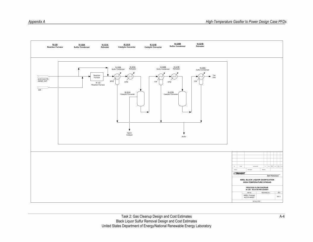
Appendix A
High-Temperature Gasifier to Power Design Case PFDs
Task 2: Gas Cleanup Design and Cost Estimates A-4 Black Liquor Sulfur Removal Design and Cost Estimates
United States Department of Energy/National Renewable Energy Laboratory
28 Aug, 2005
JOB No. DRAWING No. REV
PROCESS FLOW DIAGRAMA-120: SULFUR RECOVERY
NREL BLACK LIQUOR GASIFICATIONHIGH-TEMPERATURE SYNGAS
No. DATE REVISIONS BY CHKD DESIGNSUPV. ENGR. PROJ.
ENGR. APPRV.
SCALE: DESIGNED: DRAWN:
San Francisco
NREL ContractACO-5-44027 REV 1
ReactionFurnace
R-121ACatalytic Converter
R-121BCatalytic Converter
BFW STM
SpentCatalyst
Sulfur
CW CW
TailGas
ACID GAS FR. AMINE UNIT
AIR
R-120Reaction Furnace
R-120Reaction Furnace
H-120ASulfur Condenser
H-121AReheater
R-121ACatalytic Converter
H-120BSulfur Condenser
H-121BReheater
R-121BCatalytic Converter
H-120ASulfur Condenser
H-121AReheater
H-120BSulfur Condenser
H-121BReheater H-120C
Sulfur Condenser
STM

Task 2: Gas Cleanup Design and Cost Estimates B-1 Black Liquor Sulfur Removal Design and Cost Estimates United States Department of Energy/National Renewable Energy Laboratory
Appendix B Low-Temperature Gasifier to Power Design Case PFDs
The Claus Sulfur recovery unit shown here is for general information purpose only, and was not explicitly sized as part of the project scope. A cost estimate for this unit and a Tail Gas Treating process is provided in the equipment list.

Appendix B Low-Temperature Gasifier to Power Design Case PFDs
Hydrogen lb/hr 14,617 14,617 14,617 14,617 - - CO lb/hr 77,854 77,853 77,853 77,853 - - CO2 lb/hr 79,095 79,161 79,161 79,161 - - Methane (CH4) lb/hr 6,547 6,547 6,547 6,547 - - H2O lb/hr 9,027 9,003 9,003 9,003 8,636 8,636 COS lb/hr 105 15 15 15 - - H2S lb/hr 9,626 9,672 9,672 9,672 - - Ammonia (NH3) lb/hr - - - - - - Argon lb/hr - - - - - - Nitrogen lb/hr - - - - - -
Unit 100 101 102 103 200 201 Mass Flow lb/hr 196,870 196,870 196,868 196,868 8,636 8,636 Temperature F 325 325 240 110 220 230 Pressure psia 336.5 331.5 326.5 321.5 25.0 20.0 Vapour Fraction 1.00 1.00 1.00 0.97 0.00 1.00Molecular Weight 15.1 15.1 15.1 15.1 18.0 18.0 Heat Flow MMBtu/hr -480.5 -480.5 -488.9 -509.7 -57.5 -49.1Components
Task 2: Gas Cleanup Design and Cost Estimates B-2 Black Liquor Sulfur Removal Design and Cost Estimates United States Department of Energy/National Renewable Energy Laboratory
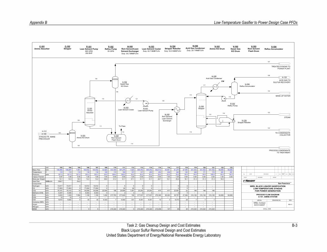
Appendix B Low-Temperature Gasifier to Power Design Case PFDs
V-104Reflux Accumulator
H-102Rich Solvent/Lean SolventExchanger
P-101Lean Solvent Pump
P-102Reflux Pump
111
113
117
118
106
V-103Rich SolventFlash Drum
TREATED SYNGAS TO POWER PLANT
ACID GAS TOSULFUR RECOVERY
SYNGAS FR. AMINE PRECOOLER
V-102Sweet GasKO Drum
C-101Amine Absorber
V-103Rich SolventFlash Drum
P-101Lean Solvent Pump
860 GPM200 BHP
C-102Stripper
P-102Reflux Pump
55 GPM
H-103Lean Solvent Cooler
Duty: 22.7 MMBTU/hr
H-104Stripper ReboilerDuty: 54.9 MMBTU/hr
V-101Amine KO Drum
H-102Rich Solvent/Lean Solvent ExchangerDuty: 30.2 MMBTU/hr
V-104Reflux Accumulator
H-105Acid Gas Condenser
Duty: 29.7 MMBTU/hr
A-100H-101
CW
H-103Lean Solvent Cooler
V-102Sweet GasKO Drum
C-101Amine
Absorber
C-102Stripper
119
109
110
114
107
H-104Stripper Reboiler
115116 122
123
112
H-105Acid Gas Condenser
108
103
A-120
V-101Amine KO Drum
104
105
PROCESS CONDENSATE TO TREATMENT
TO CONDENSATE COLLECTOR
120
To Flare
121
124
MAKE-UP WATER
STEAM
29 Dec, 2005
JOB No. DRAWING No. REV
PROCESS FLOW DIAGRAMA-101: AMINE SYSTEM
NREL BLACK LIQUOR GASIFICATIONLOW-TEMPERATURE SYNGAS
FOR POWER GENERATION
No. DATE REVISIONS BY CHKD DESIGNSUPV. ENGR. PROJ.
ENGR. APPRV.
SCALE: DESIGNED: DRAWN:
San Francisco
NREL ContractACO-5-44027 REV 0
Unit 103 104 105 106 107 108 110 111 112 113 114 115 116 117 Mass Flow lb/hr 196,868 188,887 7,981 154,832 154,832 33,820 433,309 467,276 1,824 465,452 465,452 492,512 60,881 61,275 Temperature F 110 110 110 118 118 130 110 160 157 157 200 253 248 220 Pressure psia 321.5 321.5 321.5 323.3 323.3 25.0 326.5 326.5 30.0 30.0 30.0 28.0 25.0 25.0 Vapour Fraction 0.97 1.00 0.00 1.00 1.00 1.00 0.00 0.00 1.00 0.00 0.05 0.00 1.00 1.00Molecular Weight 15.1 15.0 18.0 13.2 13.2 38.6 31.2 31.7 37.1 31.7 31.7 28.7 18.1 25.6 Heat Flow MMBtu/hr -509.7 -54.0ComponentsHydrogen lb/hr 14,617 14,617 0 14,612 14,612 0 - 5 5 0 0 - - 0 CO lb/hr 77,853 77,853 0 77,834 77,834 0 - 22 22 0 0 - - 0 CO2 lb/hr 79,161 79,143 19 54,648 54,648 23,045 196 24,699 1,457 23,242 23,242 674 477 23,067 Methane (CH4) lb/hr 6,547 6,546 0 6,543 6,543 0 - 2 2 0 0 - - 0 H2O lb/hr 9,003 1,049 7,954 1,155 1,155 1,430 217,783 217,645 108 217,537 217,537 276,369 60,263 28,797 COS lb/hr 15 15 0 - - - - - - - - - - - H2S lb/hr 9,672 9,665 8 40 40 9,344 7 9,582 231 9,351 9,351 10 3 9,373 Ammonia (NH3) lb/hr - - - - - - - - - - - - - - Argon lb/hr - - - - - - - - - - - - - - Nitrogen lb/hr - - - - - - - - - - - - - - MDEA lb/hr - - - 0 0 - 215,322 215,322 0 215,322 215,322 215,459 137 38
118 119 120 121 122 123 27,456 431,632 431,632 431,632 58,888 58,888
130 248 171 172 281 281 25.0 25.0 25.0 326.5 50.0 50.0 0.00 0.00 0.00 0.00 1.00 0.0018.1 31.3 31.3 31.3 18.0
0 - - - 0 - - -
22 196 196 196 0 - - -
27,368 216,106 216,106 216,106 58,888 58,888 - - - - 29 7 7 7
- - - - - - - - - - - - 38 215,322 215,322 215,322
Task 2: Gas Cleanup Design and Cost Estimates B-3 Black Liquor Sulfur Removal Design and Cost Estimates United States Department of Energy/National Renewable Energy Laboratory

Appendix B
Low-Temperature Gasifier to Power Design Case PFDs
Task 2: Gas Cleanup Design and Cost Estimates B-4 Black Liquor Sulfur Removal Design and Cost Estimates
United States Department of Energy/National Renewable Energy Laboratory

Task 2: Gas Cleanup Design and Cost Estimates C-1 Black Liquor Sulfur Removal Design and Cost Estimates United States Department of Energy/National Renewable Energy Laboratory
Appendix C High-Temperature Gasifier to Chemicals Design Case PFDs
The Claus Sulfur recovery unit shown here is for general information purpose only, and was not explicitly sized as part of the project scope. A cost estimate for this unit and a Tail Gas Treating process is provided in the equipment list.

Appendix C High-Temperature Gasifier to Chemicals Design Case PFDs
Hydrogen lb/hr 7,133 4,208 2,924 5,481 9,689 9,689 9,689 9,689 - - - - - CO lb/hr 94,013 55,467 38,545 3,026 58,494 58,494 58,494 58,494 - - - - - CO2 lb/hr 77,825 45,917 31,908 87,714 133,631 133,631 133,631 133,631 - - - - - Methane (CH4) lb/hr 2,962 1,748 1,215 1,215 2,962 2,962 2,962 2,962 - - - - - H2O lb/hr 11,094 6,545 98,227 75,383 81,928 81,928 81,928 81,928 93,679 78,007 78,007 31,122 31,122 COS lb/hr 412 243 169 169 412 412 412 412 - - - - - H2S lb/hr 5,416 3,196 2,221 2,221 5,416 5,416 5,416 5,416 - - - - - Ammonia (NH3) lb/hr 8 5 3 3 8 8 8 8 - - - - - Argon lb/hr 3,396 2,004 1,392 1,392 3,396 3,396 3,396 3,396 - - - - - Nitrogen lb/hr 874 516 358 358 874 874 874 874 - - - - -
Unit 150 152 153 154 155 156 158 159 210 211 212 213 214 Mass Flow lb/hr 203,133 119,848 176,963 176,963 296,811 296,811 296,811 296,811 93,679 78,007 78,007 31,122 31,122 Temperature F 252 252 460 718 551 300 240 120 608 272 282 220 230 Pressure psia 487.3 487.3 487.3 482.3 482.3 477.3 472.3 467.3 500.0 55.0 50.0 25.0 20.0 Vapour Fraction 1.00 1.00 1.00 1.00 1.00 0.83 0.74 0.70 1.00 0.00 1.00 0.00 1.00Molecular Weight 20.8 20.8 19.2 19.2 19.9 19.9 19.9 19.9 18.0 18.0 18.0 18.0 18.0 Heat Flow MMBtu/hr -518.7 -306.0 -731.3 -731.3 -1,037.3 -1,110.9 -1,141.4 -1,172.2 -518.7 -515.4 -441.8 -207.4 -176.9Components
Task 2: Gas Cleanup Design and Cost Estimates C-2 Black Liquor Sulfur Removal Design and Cost Estimates United States Department of Energy/National Renewable Energy Laboratory

Appendix C High-Temperature Gasifier to Chemicals Design Case PFDs
V-114Reflux Accumulator
H-113Lean/Rich Solvent
Exchanger
P-111Lean Solvent Pump
167
169
173
174
162
V-112Rich Flash Drum
SYNGAS TO ZnO PREHEATER
ACID GAS TOSULFUR RECOVERY
SYNGAS FROM SOLVENT PRECOOLER
V-115Sweet GasKO Drum
C-111H2S Absorber
V-112Rich SolventFlash Drum
P-111Lean Solvent
Pump
C-113Stripper P-114
Reflux Pump
H-115Lean Solvent
Cooler
H-117Stripper Reboiler
V-111KO Drum
H-113Rich/Lean Solvent
Exchanger
V-114Reflux Accumulator
H-116Acid Gas
Condenser
A-100H-100
CW
C-111H2S
Absorber
C-113Stripper
175176
183
170
164
H-117Stripper Reboiler
171172
186
187
168159 (NOTE 1)
A-112
A-120
V-111KO Drum
161
160
PROCESS CONDENSATE TO TREATMENT
TO CONDENSATE COLLECTOR
177
C-112CO2
Absorber
V-115Sweet Syngas
KO Drum
H-114Loaded Solvent
Cooler
H-115Lean Solvent
Cooler
181
163
V-113Flash Drum
(note 2)
180
P-113Semi-Lean Solvent PumpP-112
Loaded Pump
184166
185178
H-116Acid Gas Condenser
P-114Reflux Pump
CW
182
CO2 TO VENT
165
PROCESS CONDENSATE TO TREATMENT
H-115
C-112CO2 Absorber
P-112LoadedSolvent Pump
P-113Semi-Lean
Solvent Pump
V-113Flash Drum
H-114Loaded Solvent
Cooler
NOTES:
1. MATERIAL BALANCE PROVIDED BY UDHE BASED ON PROPRIETARY SIMULATION TOOLS. DESIGN PRESENTED IS A GENERIC TWO ABSORBER SYSTEM, AND MAY REQUIRE MODIFICATIONS BASED ON INLET COMPOSITION AND PRODUCT REQUIREMENTS
2. MULTIPLE FLASH STAGES MAY BE NECESSARY. DEPENDING ON COMPOSITION, ADDITIONAL TREATMENT MAY BE REQUIRED
MAKE-UP WATER
LP STEAM
21 Dec, 2005
JOB No. DRAWING No. REV
PROCESS FLOW DIAGRAMA-111: AMINE SYSTEM
NREL BLACK LIQUOR GASIFICATIONHIGH-TEMPERATURE SYNGAS FOR CHEMICALS PRODUCTION
No. DATE REVISIONS BY CHKD DESIGNSUPV. ENGR. PROJ.
ENGR. APPRV.
SCALE: DESIGNED: DRAWN:
San Francisco
NREL ContractACO-5-44027 REV 0
CW
CO2 to Vent(Note 2)
Unit 159 160 161 164 165 166 168 178 182 Mass Flow lb/hr 296,811 80,413 216,398 82,013 15,698 520,811 62,508 484,834 55,865 Temperature F 120 120 120 102 113 43 33 Pressure psia 462.3 462.3 462.3 454.0 23.2 72.5 16.0 Vapour Fraction 1.00 0.00 1.00 1.00 1.00 1.00 1.00Molecular Weight 19.9 18.0 20.7 11.2 38.6 43.8 43.8 ComponentsHydrogen lb/hr 9,689 - 9,689 9,610 - - 53 - 1 CO lb/hr 58,494 - 58,494 56,462 0 - 934 - 41 CO2 lb/hr 133,631 - 133,631 8,893 9,369 - 61,173 - 55,645 Methane (CH4) lb/hr 2,962 - 2,962 2,664 1 - 254 - 43 H2O lb/hr 81,928 80,413 1,515 18 447 - 27 - 84 COS lb/hr 412 - 412 1 303 - 57 - 51 H2S lb/hr 5,416 - 5,416 0 5,416 - - - - Solvent lb/hr - - - - - 520,811 - 484,834 - Argon lb/hr 3,396 - 3,396 3,388 - - 7 - - Nitrogen lb/hr 874 - 874 874 - - - - -
Task 2: Gas Cleanup Design and Cost Estimates C-3 Black Liquor Sulfur Removal Design and Cost Estimates United States Department of Energy/National Renewable Energy Laboratory

Appendix C High-Temperature Gasifier to Chemicals Design Case PFDs
Unit 164 190 191 215 216 Mass Flow lb/hr 82,013 82,013 82,012 29,748 29,748 Temperature F 102 750 750 775 281 Pressure psia 454.0 454.0 450.0 50.0 50.0 Vapor Fraction 1.00 1.00 1.00 1.00 0.00Molecular Weight 11.2 11.2 11.2 18.0 18.0 Heat Flow MMBtu/hr -142.1 -107.3 -107.3 -161.4 -196.3ComponentsHydrogen lb/hr 9,610 9,610 9,610 - - CO lb/hr 56,462 56,462 56,462 - - CO2 lb/hr 8,893 8,893 8,893 - - Methane (CH4) lb/hr 2,664 2,664 2,664 - - H2O lb/hr 18 18 18 29,748 29,748 COS lb/hr 1 1 - - - H2S lb/hr - - - - - Ammonia (NH3) lb/hr - - - - - Argon lb/hr 3,388 3,388 3,388 - - Nitrogen lb/hr 874 874 874 - -
Task 2: Gas Cleanup Design and Cost Estimates C-4 Black Liquor Sulfur Removal Design and Cost Estimates United States Department of Energy/National Renewable Energy Laboratory

Appendix C
High-Temperature Gasifier to Chemicals Design Case PFDs
Task 2: Gas Cleanup Design and Cost Estimates C-5 Black Liquor Sulfur Removal Design and Cost Estimates
United States Department of Energy/National Renewable Energy Laboratory

Task 2: Gas Cleanup Design and Cost Estimates D-1 Black Liquor Sulfur Removal Design and Cost Estimates United States Department of Energy/National Renewable Energy Laboratory
Appendix D Low-Temperature Gasifier to Chemicals Design Case PFDs
The Claus Sulfur recovery unit shown here is for general information purpose only, and was not explicitly sized as part of the project scope. A cost estimate for this unit and a Tail Gas Treating process is provided in the equipment list.
Appendix D Low-Temperature Gasifier to Chemicals Design Case PFDs
V-114Reflux Accumulator
H-112Lean/Rich Solvent
Exchanger
P-111Lean Solvent Pump
161
163
167
168
156
V-112Rich Flash Drum
SYNGAS TO ZnO PREHEATER
ACID GAS TOSULFUR RECOVERY
SYNGAS FROM LP STEAM GENERATOR (H-110, NOT SHOWN)
V-115Sweet GasKO Drum
C-111H2S Absorber
V-112Rich SolventFlash Drum
P-111Lean Solvent
Pump
C-113Stripper
P-114Reflux Pump
H-114Loaded Solvent
Cooler
H-116Stripper Reboiler
V-111 KO Drum
H-112Rich/Lean Solvent
Exchanger
V-114Reflux Accumulator
H-115Acid Gas
Condenser
A-100H-100
CW
C-111H2S
Absorber
C-113Stripper
169170
178
164
158
H-116Stripper Reboiler
165166
181
182
162150
A-112
A-120
V-111 KO Drum
155
154
PROCESS CONDENSATE TO TREATMENT
TO CONDENSATE COLLECTOR
171
C-112CO2
Absorber
V-115Sweet Syngas
KO Drum
H-114Loaded Solvent
Cooler
H-113Lean Solvent
Cooler
176
157
V-113Flash Drum
(note 2)
174
175
P-113Semi-Lean Solvent PumpP-112
Loaded Pump
179160
180172
H-115Acid Gas Condenser
P-114Reflux Pump
CW
177
CO2 TO VENT
159
PROCESS CONDENSATE TO TREATMENT
H-115
C-112CO2 Absorber
P-112Loaded Pump
P-113Semi-Lean
Solvent Pump
V-113Flash Drum
H-113Lean Solvent
Cooler
LP STEAM
MAKE-UP WATER
CW
153
H-111Solvent Precooler
H-111Solvent Precooler
21 Dec, 2005
JOB No. DRAWING No. REV
PROCESS FLOW DIAGRAMA-110: AMINE SYSTEM
NREL BLACK LIQUOR GASIFICATIONLOW-TEMPERATURE SYNGAS FOR CHEMICALS PRODUCTION
No. DATE REVISIONS BY CHKD DESIGNSUPV. ENGR. PROJ.
ENGR. APPRV.
SCALE: DESIGNED: DRAWN:
San Francisco
NREL ContractACO-5-44027 REV 0
NOTES:
1. MATERIAL BALANCE PROVIDED BY UDHE BASED ON PROPRIETARY SIMULATION TOOLS. DESIGN PRESENTED IS A GENERIC TWO ABSORBER SYSTEM, AND MAY REQUIRE MODIFICATIONS BASED ON INLET COMPOSITION AND PRODUCT REQUIREMENTS
2. MULTIPLE FLASH STAGES MAY BE NECESSARY. DEPENDING ON COMPOSITION, ADDITIONAL TREATMENT MAY BE REQUIRED
CO2 to Vent(Note 2)
Hydrogen lb/hr 14,617 - 14,617 14,539 - - 74 - 5 CO lb/hr 77,853 - 77,853 76,738 1 - 980 - 134 CO2 lb/hr 79,152 - 79,512 24,146 10,831 - 24,759 - 19,413 Methane (CH4) lb/hr 6,547 - 6,547 6,103 5 - 308 - 129 H2O lb/hr 9,003 7,634 1,369 33 623 - 9 - 28 COS lb/hr 105 - 105 0 104 - 1 - - H2S lb/hr 9,676 - 9,676 0 9,675 - - - - Solvent lb/hr - - - - - 831,898 - 993,691 - Argon lb/hr - - - - - - - - - Nitrogen lb/hr - - - - - - - - -
Unit 153 154 155 158 159 160 162 172 177 Mass Flow lb/hr 196,953 7,634 189,319 121,560 21,240 831,898 26,133 993,691 19,709 Temperature F 120 120 120 98 113 43 33 Pressure psia 326.5 326.5 326.5 318.5 23.2 72.5 16.0 Vapour Fraction 1.00 0.00 1.00 1.00 1.00 1.00 1.00Molecular Weight 15.1 18.0 15.0 11.1 37.4 40.0 43.0 Components
Task 2: Gas Cleanup Design and Cost Estimates D-2 Black Liquor Sulfur Removal Design and Cost Estimates United States Department of Energy/National Renewable Energy Laboratory

Appendix D Low-Temperature Gasifier to Chemicals Design Case PFDs
Hydrogen lb/hr 14,538 14,538 14,538 - - CO lb/hr 76,738 76,738 76,738 - - CO2 lb/hr 24,146 24,146 24,146 - - Methane (CH4) lb/hr 6,103 6,103 6,103 - - H2O lb/hr 33 33 33 44,977 44,977 COS lb/hr - - - - - H2S lb/hr - - - - - Ammonia (NH3) lb/hr - - - - - Argon lb/hr - - - - - Nitrogen lb/hr - - - - -
Unit 158 190 191 212 213 Mass Flow lb/hr 121,560 121,560 121,560 44,977 44,977 Temperature F 98 750 750 775 281 Pressure psia 318.5 318.0 313.0 50.0 50.0 Vapour Fraction 1.00 1.00 1.00 1.00 0.00Molecular Weight 11.1 11.1 11.1 18.0 18.0 Components
Task 2: Gas Cleanup Design and Cost Estimates D-3 Black Liquor Sulfur Removal Design and Cost Estimates United States Department of Energy/National Renewable Energy Laboratory

Appendix D
Low-Temperature Gasifier to Chemicals Design Case PFDs
Task 2: Gas Cleanup Design and Cost Estimates D-4 Black Liquor Sulfur Removal Design and Cost Estimates
United States Department of Energy/National Renewable Energy Laboratory

Task 2: Gas Cleanup Design and Cost Estimates E-1 Black Liquor Sulfur Removal Design and Cost Estimates United States Department of Energy/National Renewable Energy Laboratory
Appendix E Equipment Lists
The equipment lists for all four black liquor gasification cases are shown below, with the two high temperature and two low temperature cases placed together on the same sheet.
Appendix E Equipment Lists
High Temperature Syngas to Power and Chemicals Cases
Item No Description Type Quantity Per Train Size Weight
lbs
Head
PSI
Design Duty T
ºFPSIG
P
Design
P T
PSIG ºF
Operating
Power Useage
(No.) HP
Materials Price, total (unistalled)
Price Escalated, total (uninstalled)
Total Installed Cost Quote Source Comments
Q2 2004 Cost Index (US $)
Q2 2005 Cost Index (US $) (US $)
Power Generation Case
Reactors R-100 COS Hydrolysis Total
Vertical 1 14' ID x 15' - 9" T/T 132,230 375520 472 325 CS $315,598 $374,141 Sud-Chemie 2400 ft3 catalyst required $374,141
Heat Exchangers
Total H-101 Amine Pre-cooler
H-100 Syngas Cooler/ LP Steam Generator
Shell & Tube
Shell & Tube
1
1 6' ID x 12' T-T
Surface area: 7907 SQFT 4' - 1" ID x 8' T-T
Surface area: 3120 SQFT 20.1 MMBTU/hr
6.8 MMBTU/hr T 25 280 S 515 375 T 65 150 S 510 290
10 230 467 326 50 100
462 240
CS CS CS CS
$287,585 ICARUS $87,300 $99,155
ICARUS $165,900 $188,429
Packaged Units A-101 Amine Unit A-120 Claus Plant with Tail Gas Treating
TOTAL EQUIPMENT COST, (excld. Package units)
TOTAL INSTALLED COST
$8,500,000 GRI Cost Curve $17,622,000 Scaled from Ortloff quote 63.3 STPD sulfur production
$661,726 $1,700,636 $27,822,636
Chemicals Production Case
Reactors R-110 LT Shift Reactor R-112 ZnO Sulfur Removal Beds R-113 ZnO Sulfur Removal Beds Total
Vertical Vertical Vertical
1 1 1
4' - 11" ID x 8' T/T 7' - 2" ID x 10' T/T 7' - 2" ID x 10' T/T
46,100 66,800 66,800
770 800 800
515 480 480
467 718 437 750 437 750
CS CS CS
$230,500 Sud-Chemie 151 ft3 catalyst required $333,400 Johnson Matthey $333,400 Johnson Matthey $897,300
818 ft3 total catalyst volume required
Heat Exchangers
Total
H-110 LT Shift Cooler/ LP Steam Generator
H-112 Solvent Pre-cooler
H-111 Syngas Cooler/ LP Steam Generator
H-118 ZnO Bed Preheater
Shell & Tube
Shell & Tube
Shell & Tube
Shell & Tube
1
1
2
1
7' - 8" ID x 20' T-T Surface area: 29185 SQFT
7' - 3" ID x 20' T-T Surface area: 20268 SQFT
4' - 9" ID x 8' T-T Surface area: 4270 SQFT
4' - 6" ID x 20' T-T Surface area: 10672 SQFT
30.4 MMBTU/hr
73.59 MMBTU/hr
30.9 MMBTU/hr
35.1 MMBTU/hr
T 55 350 S 515 600 T 25 280 S 510 350 T 65 150 S 500 290 T 490 800 S 50 825
40 282 467 551 10 230
462 300 50 100
452 240 442 750 35 775
CS CS CS CS CS CS CS CS
$1,975,383
$899,900 ICARUS $1,022,106
$578,400 ICARUS $656,947
$113,100 $128,459 ICARUS
$147,800 $167,871 ICARUS
Packaged Units
A-111 Genosorb Unit
A-120 Claus Plant with Tail Gas Treating
TOTAL EQUIPMENT COST, (excld. Package units)
TOTAL INSTALLED COST
$30,125,000 Scaled estimates from
previous physical solvent studies and IGCC data
Physical solvent necessary for CO2 removal and to concentrate
the H2S for Claus Feed
$17,677,000 Scaled from Ortloff quote 63.6 STPD sulfur production
$2,872,683 $7,382,796 $55,184,796
Task 2: Gas Cleanup Design and Cost Estimates Black Liquor Sulfur Removal Design and Cost Estimates
United States Department of Energy/National Renewable Energy Laboratory
E-2
Appendix E Equipment Lists
Low Temperature Syngas to Chemicals Design Case
Item No Description Type Quantity Per Train Size Weight
lbs
Head
PSI
Design Duty T
ºFPSIG
P
Design
P T
PSIG ºF
Operating
Power Useage
(No.) HP
Materials Price, total (unistalled)
Price Escalated, total (uninstalled)
Total Installed Cost Quote Source Comments
Q2 2004 Cost Index (US $)
Q2 2005 Cost Index (US $) (US $)
Power Generation Case
Reactors R-100 COS Hydrolysis Total
Vertical 1 13' ID x 18' - 6" T/T 130,200 375355 322 325 CS $310,767 $368,414 Sud-Chemie 2470 ft3 catalyst required $368,414
Heat Exchangers
Total
H-100 Syngas Cooler/ LP Steam Generator
H-101 Amine Pre-cooler
Shell & Tube
Shell & Tube
1
1
4' - 7" ID x 12' T-T Surface area: 4433 SQFT
4' ID x 8' T-T Surface area: 2631 SQFT 20.8 MMBTU/hr
8.4 MMBTU/hr T 25 280 S 350 375 T 65 150 S 345 290
10 230 316 325 50 100
312 240
CS CS CS CS
$189,224 ICARUS $73,600 $83,595
ICARUS $93,000 $105,629
Packaged Units A-101 Amine Unit A-120 Claus Plant with Tail Gas Treating
TOTAL EQUIPMENT COST, (excld. Package units)
TOTAL INSTALLED COST
$10,200,000 GRI Cost Curve $25,036,000 Scaled from Ortloff quote 109 STPD sulfur production
$557,639 $1,433,131 $36,669,131
Chemicals Production Case
Reactors R-111 ZnO Sulfur Removal Beds R-112 ZnO Sulfur Removal Beds Total
Vertical Vertical
1 1
7' - 3" ID x 10' T/T 7' - 3" ID x 10' T/T
66,900 66,900
800 800
330 330
297 750 297 750
CS CS
$334,600 $334,600 $669,200
Heat Exchangers
Total
H-111 Solvent Pre-cooler
H-117 ZnO Bed Preheater
H-110 Syngas Cooler/ LP Steam Generator
Shell & Tube
Shell & Tube
Shell & Tube
1
1
1 4' - 7" ID x 12' T-T
Surface area: 4433 SQFT 4' - 6" ID x 8' T-T
Surface area: 3285 SQFT 6' - 2" ID x 18' T-T
Surface area: 17750 SQFT
15.6 MMBTU/hr
52.7 MMBTU/hr
8.4 MMBTU/hr T 25 280 S 350 375 T 65 150 S 355 250 T 335 800 S 50 825
10 230 316 325 50 100
322 200 302 750 35 775
CS CS CS CS CS CS
$383,560
ICARUS $104,380 $91,900
$245,800 $279,180 ICARUS
$93,000 $105,629 ICARUS
Packaged Units
A-111 Genosorb Unit
A-120 Claus Plant with Tail Gas Treating
TOTAL EQUIPMENT COST, (excld. Package units)
TOTAL INSTALLED COST
$22,400,000 Scaled estimates from
previous physical solvent studies and IGCC data
Physical solvent necessary for CO2 removal and to concentrate
the H2S for Claus Feed
$25,093,000 Scaled from Ortloff quote 109 STPD sulfur production
$1,052,760 $2,705,592 $50,198,592
Task 2: Gas Cleanup Design and Cost Estimates Black Liquor Sulfur Removal Design and Cost Estimates
United States Department of Energy/National Renewable Energy Laboratory
E-3

F1146-E(12/2004)
REPORT DOCUMENTATION PAGE Form Approved OMB No. 0704-0188
The public reporting burden for this collection of information is estimated to average 1 hour per response, including the time for reviewing instructions, searching existing data sources, gathering and maintaining the data needed, and completing and reviewing the collection of information. Send comments regarding this burden estimate or any other aspect of this collection of information, including suggestions for reducing the burden, to Department of Defense, Executive Services and Communications Directorate (0704-0188). Respondents should be aware that notwithstanding any other provision of law, no person shall be subject to any penalty for failing to comply with a collection of information if it does not display a currently valid OMB control number. PLEASE DO NOT RETURN YOUR FORM TO THE ABOVE ORGANIZATION. 1. REPORT DATE (DD-MM-YYYY)
May 2006 2. REPORT TYPE
Subcontract Report 3. DATES COVERED (From - To)
5a. CONTRACT NUMBER
DE-AC36-99-GO10337
5b. GRANT NUMBER
4. TITLE AND SUBTITLE Equipment Design and Cost Estimation for Small Modular Biomass Systems, Synthesis Gas Cleanup, and Oxygen Separation Equipment; Task 2: Gas Cleanup Design and Cost Estimates – Black Liquor Gasification
5c. PROGRAM ELEMENT NUMBER
5d. PROJECT NUMBER NREL/SR-510-39944
5e. TASK NUMBER BB06.3710
6. AUTHOR(S) Nexant Inc.
5f. WORK UNIT NUMBER
7. PERFORMING ORGANIZATION NAME(S) AND ADDRESS(ES) Nexant Inc. 101 Second St., 11th Floor San Francisco, CA 94105
8. PERFORMING ORGANIZATION REPORT NUMBER ACO-5-44027
10. SPONSOR/MONITOR'S ACRONYM(S) NREL
9. SPONSORING/MONITORING AGENCY NAME(S) AND ADDRESS(ES) National Renewable Energy Laboratory 1617 Cole Blvd. Golden, CO 80401-3393 11. SPONSORING/MONITORING
AGENCY REPORT NUMBER NREL/SR-510-39944
12. DISTRIBUTION AVAILABILITY STATEMENT National Technical Information Service U.S. Department of Commerce 5285 Port Royal Road Springfield, VA 22161
13. SUPPLEMENTARY NOTES NREL Technical Monitor: Kelly Ibsen
14. ABSTRACT (Maximum 200 Words) As part of Task 2, Gas Cleanup and Cost Estimates, Nexant investigated the appropriate process scheme for removal of acid gases from black liquor-derived syngas for use in both power and liquid fuels synthesis. Two 3,200 metric tonne per day gasification schemes, both low-temperature/low-pressure (1100°F, 40 psi) and high-temperature/high-pressure (1800°F, 500 psi) were used for syngas production. Initial syngas conditions from each of the gasifiers was provided to the team by the National Renewable Energy Laboratory and Princeton University. Nexant was the prime contractor and principal investigator during this task; technical assistance was provided by both GTI and Emery Energy.
15. SUBJECT TERMS biomass; Nexant; small modular; synthesis gas; syngas; fluidized catalytic cracking; steam methane reforming; natural gas liquids expanders; scaling; black liquor; National Renewable Energy Laboratory; NREL
16. SECURITY CLASSIFICATION OF: 19a. NAME OF RESPONSIBLE PERSON a. REPORT
Unclassified b. ABSTRACT Unclassified
c. THIS PAGE Unclassified
17. LIMITATION OF ABSTRACT
UL
18. NUMBER OF PAGES
19b. TELEPHONE NUMBER (Include area code)
Standard Form 298 (Rev. 8/98) Prescribed by ANSI Std. Z39.18