nsc-g series datasheet - newmark systems
TRANSCRIPT
NSC-G SERIESMOTION CONTROLLER
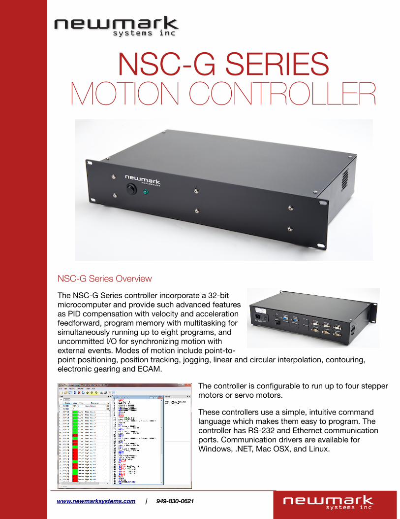
NSC-G Series OverviewThe NSC-G Series controller incorporate a 32-bit microcomputer and provide such advanced features as PID compensation with velocity and acceleration feedforward, program memory with multitasking for simultaneously running up to eight programs, and uncommitted I/O for synchronizing motion with external events. Modes of motion include point-to-point positioning, position tracking, jogging, linear and circular interpolation, contouring, electronic gearing and ECAM.
The controller is configurable to run up to four stepper motors or servo motors.
These controllers use a simple, intuitive command language which makes them easy to program. The controller has RS-232 and Ethernet communication ports. Communication drivers are available for Windows, .NET, Mac OSX, and Linux.
www.newmarksystems.com | 949-830-0621
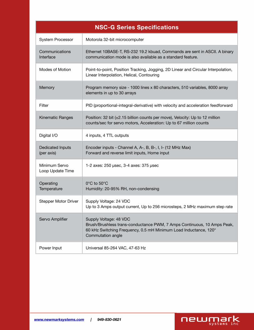
NSC-G Series SpecificationsNSC-G Series Specifications
System Processor Motorola 32-bit microcomputer
Communications Interface
Ethernet 10BASE-T, RS-232 19.2 kbuad, Commands are sent in ASCII. A binary communication mode is also available as a standard feature.
Modes of Motion Point-to-point, Position Tracking, Jogging, 2D Linear and Circular Interpolation, Linear Interpolation, Helical, Contouring
Memory Program memory size - 1000 lines x 80 characters, 510 variables, 8000 array elements in up to 30 arrays
Filter PID (proportional-integral-derivative) with velocity and acceleration feedforward
Kinematic Ranges Position: 32 bit (±2.15 billion counts per move), Velocity: Up to 12 million counts/sec for servo motors, Acceleration: Up to 67 million counts
Digital I/O 4 inputs, 4 TTL outputs
Dedicated Inputs (per axis)
Encoder inputs - Channel A, A-, B, B-, I, I- (12 MHz Max)Forward and reverse limit inputs, Home input
Minimum Servo Loop Update Time
1-2 axes: 250 µsec, 3-4 axes: 375 µsec
Operating Temperature
0°C to 50°C Humidity: 20-95% RH, non-condensing
Stepper Motor Driver Supply Voltage: 24 VDCUp to 3 Amps output current, Up to 256 microsteps, 2 MHz maximum step rate
Servo Amplifier Supply Voltage: 48 VDCBrush/Brushless trans-conductance PWM, 7 Amps Continuous, 10 Amps Peak, 60 kHz Switching Frequency, 0.5 mH Minimum Load Inductance, 120° Commutation angle
Power Input Universal 85-264 VAC, 47-63 Hz
www.newmarksystems.com | 949-830-0621

NSC-G Series Instruction Set
www.newmarksystems.com | 949-830-0621
DMC-21x3 Series
Independent Motion CommandsMR After motion—reverseWC Wait for contour dataWT Wait for timeAB Abort motionAC AccelerationBG Begin motionDC DecelerationFE Find edgeFI Find indexHM HomeIP Increment positionIT Smoothing time constantJG Jog modePA Position absolutePR Position relativePT Position trackingSP SpeedST Stop
Contour ModeCD Contour dataCM Contour modeDT Contour time intervalWC Wait for contour data
ECAM/GearingEA ECAM masterEB Enable ECAMEC ECAM table indexEG ECAM goEM ECAM modulusEP ECAM intervalEQ Disengage ECAMET ECAM table entry EW ECAM widen GA Master axis for gearingGD Engagement distance for gearingGM Gantry mode_GP Correction for gearingGR Gear ratio for gearing
Vector/Linear InterpolationCA Define vector planeCR Circular interpolation moveCS Clear motion sequenceES Elliptical scalingLE Linear interpolation endLI Linear interpolation segmentLM Linear interpolation modeST Stop motionTN TangentVA Vector accelerationVD Vector decelerationVE Vector sequence endVM Coordinated motion modeVP Vector positionVR Vector speed ratioVS Vector speedVT Smoothing time constant—vector
Instruction SetEthernetHS Handle switchIA Set IP addressIH Open IP handleIK Ethernet port blockingMB ModbusMW Modbus waitSA Send command
Servo MotorAF Analog feedbackAG* Set AMP-20540 gainAU* Set current loop gainAW* Report AMP-20540 bandwidthDV Dual velocityFA Acceleration feedforwardFV Velocity feedforwardIL Integrator limitKD Derivative constantKI Integrator constantKP Proportional constantNB Notch bandwidthNF Notch frequencyNZ Notch zeroOF OffsetPL PoleSH Servo hereTK Peak torqueTL Continuous torque limitTM Sample time
Stepper MotorAG† Set SDM-20640 gainKS Stepper motor smoothingLC Low currentQS Error magnitudeYA Step drive resolutionYB Step motor resolutionYC Encoder resolutionYR Error correctionYS Stepper position maintenance
Internal Sine CommutationBA Brushless axisBB Brushless phaseBC Brushless calibrationBD Brushless degreesBI Brushless inputsBM Brushless moduloBO Brushless offsetBS Brushless setupBZ Brushless zero
I/O AL Arm latchAQ Analog configurationCB Clear bitCO Configure I/O pointsII Input interruptOB Define output bitOC Output compare functionOP Output portSB Set bit
I/O (cont.)@AN[x] Value of analog input x@IN[x] State of digital input x@OUT[x] State of digital output x
System ConfigurationAE Amplifier errorBN Burn parametersBP Burn programBR* Brush motor enableBV Burn variables and arraysCC Configure communications portCE Configure encoder typeCF Configure unsolicited messages handlesCI Configure communication interruptCN Configure switchesCW Data adjustment bitDE Define dual encoder positionDP Define positionDR Data record update rateEO EchoIT Independent smoothingLO Lockout handleLZ Leading zeros formatMO Motor offMT Motor typePF Position formatQD Download arrayRS ResetˆRˆS Master resetVF Variable format
Math Functions@ABS[x] Absolute value of x@ACOS[x] Arc cosine of x@ASIN[x] Arc sine of x@ATAN[x] Arc tangent of x@COM[x] 1’s complement of x@COS[x] Cosine of x@FRAC[x] Fraction portion of x@INT[x] Integer portion of x@RND[x] Round of x@SIN[x] Sine of x@SQR[x] Square root of x@TAN[x] Tangent
InterrogationLA List arraysLL List labelsLS List programLV List variablesMG Message commandQH* Query hall stateQR Data recordQU Upload arrayQZ Return data record info RL Report latchRP Report command positionˆRˆV Firmware revision informationSC Stop codeTA* Tell AMP-20540 status
Interrogation (cont.)TB Tell statusTC Tell error codeTD Tell dual encoderTE Tell errorTH Tell handleTI Tell inputTP Tell positionTR Trace programTS Tell switchesTT Tell torqueTV Tell velocityTZ Tell I/O configurationWH Which handle
ProgrammingBK BreakpointDA Deallocate variables/arraysDL Download programDM Dimension arraysED Edit programELSE Conditional statementENDIF End of cond. statementEN End programHX Halt executionIF If statementIN Input variableJP JumpJS Jump to subroutineNO No-operation—for commentsRA Record arrayRC Record intervalRD Record dataRE Return from error routineREM Remark programRI Return from interrupt routineSL Single stepUL Upload programXQ Execute programZS Zero stack
‘ Comment
Error ControlBL Backward software limitER Error limitFL Forward software limitOE Off-on-error functionTW Timeout for in-position
TrippointAD After distanceAI After inputAM After motion profilerAP After absolute positionAR After relative distanceAS At speedAT After timeAV After vector distanceMC Motion completeMF After motion—forward
Ethernet/RS232 Econo Series, 1–8 axes
www.galilmc.com / Galil Motion Control, Inc. 3
ECONO
† For use with SDM-20640* For use with AMP-20540

NSC-G Series Dimensions
www.newmarksystems.com | 949-830-0621

NSC-G Series Motor - Signals Pin Assignment
DB-9 Female Description1. Phase A
2. Phase A’
3. Phase B
4. Phase B’
DB-9 Male Description1. Forward Limit
2. Reverse Limit
3. Ground
4. Home Input
5. +5 VDC Output
HD-15 Male Description1. Forward Limit
2. Reverse Limit
3. Limit Ground
4. Encoder Ground
5. +5V Encoder Power
6. Ch. A
7. Ch. A-
8. Ch. B
9. Ch. B-
10. Index +
11. Index -
12. Home Input
Motor Connector Signals Connector (Encoder Version)
Signals Connector
www.newmarksystems.com | 949-830-0621
Stepper Motor Version
Servo Motor Version
DB-9 Female Description1. Phase A
2. Phase B
3. Phase C
HD-15 Male Description1. Ch. A-
2. Ch. A
3. Ch. B+
4. Ch. B-
5. Index +
6. Index -
7. Hall A
8. Hall B
9. Hall C
10. Ground
11. +5 VDC Output
12. Home Input
13. Reverse Limit
14. Forward Limit
Motor Connector Signals Connector

NSC-G Series Digital I/O - RS-232 Pin Assignment
DB-9 Male Description1. Ground
2. Input 1
3. Input 2
4. Input 3
5. Input 4
6. Output 1
7. Output 2
8. Output 3
9. Output 4
DB-9 Female Description1. Carrier Detect
2. RxD
3. TxD
4. Data Terminal Ready
5. Ground
6. Data Set Ready
7. Request to Send
8. Clear to Send
9. Ring Indicator
Digital I/O Connector RS-232 Connector
www.newmarksystems.com | 949-830-0621
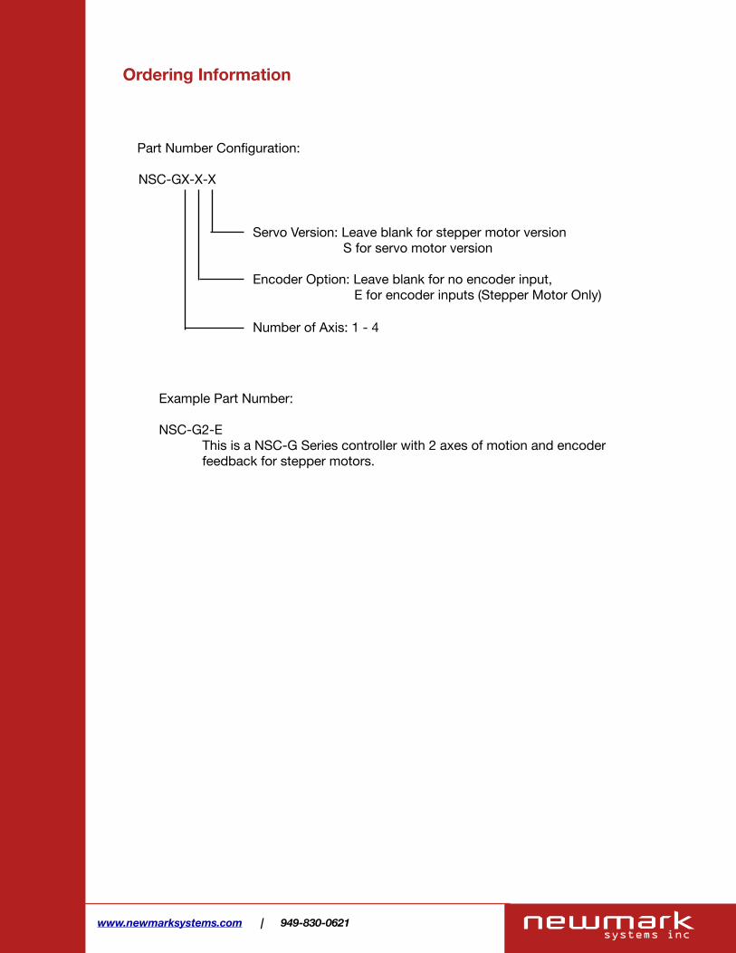
Ordering Information
Part Number Configuration:
www.newmarksystems.com | 949-830-0621
NSC-GX-X-X
Servo Version: Leave blank for stepper motor version S for servo motor version
Encoder Option: Leave blank for no encoder input, E for encoder inputs (Stepper Motor Only)
Number of Axis: 1 - 4
Example Part Number: NSC-G2-E This is a NSC-G Series controller with 2 axes of motion and encoder feedback for stepper motors.