nsp-003-001 - guidance for the installation and ... · check polarity & earth loop impedance,...
TRANSCRIPT

Document reference NSP/003/001 Document Type: Code of Practice
Version:- 1.1 Date of Issue:- September 2016 Page 1 of 22
CAUTION! - This document may be out of date if printed
NSP-003-001 - Guidance for the Installation and Commissioning of a Ground Mounted Remote Control System
1. Purpose
The purpose of this document is to provide guidance for the Installation and Commissioning of a Ground Mounted Remote Control System on Northern Powergrid Distribution networks.
This document supersedes the following documents, all copies of which should be destroyed.
Ref. Version Date Title
NSP 003 001 1.0 September 2015
GUIDANCE FOR THE INSTALLATION AND COMMISSIONING OF A GROUND MOUNTED REMOTE CONTROL SYSTEM
2. Scope
This document applies to all Northern Powergrid staff and approved contractors working on the Northern Powergrid distribution network. The document provides guidance on the expected procedure for surveying, planning, installing, commissioning and asset recording of a Ground mounted remote control system.
Document reference NSP/003/001 Document Type: Code of Practice
Version:- 1.1 Date of Issue:- September 2016 Page 2 of 22
CAUTION! - This document may be out of date if printed
2.1. Table of Contents
1. Purpose ....................................................................................................................................................................... 1
2. Scope .......................................................................................................................................................................... 1
2.1. Table of Contents ................................................................................................................................................... 2
3. General ....................................................................................................................................................................... 3
3.1. Preliminary Site Survey ......................................................................................................................................... 3
3.2. Site Installation ....................................................................................................................................................... 4
3.2.1. RTU Installation & Checks ................................................................................................................................ 4
3.2.2. Fault Passage Indicator Installation and Testing ................................................................................................ 6
3.2.3. Radio and Antenna Installation .......................................................................................................................... 8
3.2.4. UDE Kit/Remote Push Buttons.......................................................................................................................... 8
3.2.5. Outdoor Sites ..................................................................................................................................................... 9
3.2.6. Commissioning .................................................................................................................................................. 9
3.2.7. Asset Information Recording and reporting ....................................................................................................... 9
4. References ................................................................................................................................................................ 10
4.1. External Documentation ....................................................................................................................................... 10
4.2. Internal documentation ......................................................................................................................................... 10
4.3. Amendments from Previous Version ................................................................................................................... 10
5. Definitions ................................................................................................................................................................ 10
6. Authority for issue .................................................................................................................................................... 11
6.1. CDS Assurance .................................................................................................................................................... 11
6.2. Author .................................................................................................................................................................. 11
6.3. Technical Assurance ............................................................................................................................................ 11
6.4. Authorisation ........................................................................................................................................................ 11
Appendix 1- Site arrangements .......................................................................................................................................... 12

Document reference NSP/003/001 Document Type: Code of Practice
Version:- 1.1 Date of Issue:- September 2016 Page 3 of 22
CAUTION! - This document may be out of date if printed
3. General
Northern Powergrid (the Company) operates a ground mounted remote control system across the Company’s distribution substation network. This system enables the Company to monitor plant on the distribution network and carry out remote switching from the Company’s system control centres.
In order to strengthen the capability and capacity of this system, the Company requires the commissioning of remote control OEM and retrofit actuators at strategically identified sites on the distribution network across both the Northern Powergrid Northeast Ltd and Northern Powergrid Yorkshire plc licence areas. This will minimise the impact and duration of unplanned fault related loss of supplies to reduce the number of Customer Minutes Lost (CML’s) and therefore supporting our vision of providing an excellent Customer Service.
3.1. Preliminary Site Survey
Prior to the installation of the equipment and commissioning of the site, a site survey shall be carried out. A record of the existing general site layout shall be produced; to include a diagram for the purposes of confirming:
The switchgear type, feeder names and positions,
The quantity, Make and model of Fault Passage Indicators (FPI’s) on site, and
Position of a suitable power supply for the RTU cabinet.
The proposed position of the RTU cabinet will be marked on the sketch diagram and on site, and also with the proposed routes for power, FPI and actuator cables based on the lengths quoted on the survey sheet. Checks shall be carried out on modern switchgear to determine the availability of internal wiring harnesses and switch position indication.
Photographic and/or video records will be taken as a record to help assist in any queries when the installation process starts and also in the preparation of the schedule created to “map” logic points into the Network Management NMS system (NMS). These Photographs and short video of the substation shall include;
The substation name plate
The switchgear type and feeder names
The location of existing FPI’s showing type and feeder(s) monitored
Any existing installations,
The proposed location of RTU cabinet,
The suggested power supply point, and
Any other details or items that may be relevant to the installation and commissioning of the site.
Where no FPI's are fitted to the existing switchgear, the suitability of earthing arrangements for fitting CT's and FPI's should be confirmed. In some cases where no insulated gland has been fitted it may be necessary to alter earthing arrangements which may require a feeder to be isolated and work carried out under safety documents.
The proposed position of the RTU cabinet shall be marked on the wall and consideration will be given to the location of the power supply, local operation of the RTU cabinet and access to the switchgear.
Document reference NSP/003/001 Document Type: Code of Practice
Version:- 1.1 Date of Issue:- September 2016 Page 4 of 22
CAUTION! - This document may be out of date if printed
Consideration should be given to positioning of the RTU so as to keep control cable length as short as possible.
The proposed power supply shall be checked to confirm power is available (no blown fuses) and that the socket / spur is fed direct from the LV distribution network source and not via a device such as a thermostatic supply for heaters.
Where the supply is from a 3rd party i.e. commercial customer, contact details will be obtained so access can be arranged to isolate circuits for connection of the RTU supply.
If the position of the RTU is at the rear of the switchgear to be operated (i.e. UDE substations) then a UDE/remote push button kit will be installed. This allows the operator to remain in a position to exit the substation quickly if the need arises. This is normally the case in small package substations were space is restricted. These kits can be used in other situations where the location of the RTU may be better suited behind the switchgear. The site survey should provide enough information to produce a materials list and the information required to input into NMS.
The proposed position of the RTU cabinet is required to allow the radio survey to be completed before the equipment is installed. Northern Powergrid Telecoms will strive to achieve a suitable radio signal within a few meters so a standard 5m aerial can be used. The aerial position will be marked by NPg Telecoms prior to the installation of the RTU equipment.
The survey should also identify any site issues. They may include access issues, vandalism, and poor condition of buildings or plant including LV.
3.2. Site Installation
The following procedure shall be adopted in the installation and setting up of the RTU cabinets and actuators.
3.2.1. RTU Installation & Checks
Mount the RTU on the wall confirming free access is available to open the door fully and allowing operation of the local push buttons.
Suitable wall fixings to mount on to various wall surfaces shall be used.
Where the substation building is a GRP type the preferred option will be to mount the RTU on a freestanding frame. Where limited space precludes this, it may be necessary to mount direct to the GRP wall using a wooden frame arrangement (see attached photograph).
Care shall be taken with all fixings to ensure they are drilled to the correct depth and not through single skinned substation walls damaging the outer surface. Any damage will be made good to Northern Powergrid satisfaction.
The location of the cabinet should not prohibit any manual operations of the switchgear.

Document reference NSP/003/001 Document Type: Code of Practice
Version:- 1.1 Date of Issue:- September 2016 Page 5 of 22
CAUTION! - This document may be out of date if printed
A suitable LV supply point will be found and a 13A un-switched fuse spur connected to the point of supply (in preference to a plug and socket arrangement).
A label shall be fixed at this point to make anyone aware that if the supply is disconnected that the control centre will receive an alarm stating loss of supply. See attached drawing.
The general cabling arrangement will consist of:
A single phase LV supply to the RTU cabinet,
Separate control cable from the RTU to each actuator,
Separate control cable from the RTU to each FPI,
An additional separate 230v reset supply to each FPI.
As well as an LV supply to the RTU a single socket outlet should be positioned adjacent to the control cabinet.
The preferred source for LV supply will be in the following order;
Transformer mounted cabinet LV auxiliary terminals
Substation LV wiring distribution board
Existing LV socket outlet or switch
Via approved fused busbar connectors feeding a fused spur
Customer LV supplies where no local NPG supply can be obtained
The proposed power supply and all other wiring shall be installed in accordance with NSP/008/001 Guidance on distribution substation design: Substation heating, lighting and 240/415v socket outlets and IMP/010/011 Code of practice for earthing of LV networks and HV distribution substations.
SY cables (or alternative) shall be terminated in CXT brass glands to allow for bonding of the metallic sheath at the RTU. Check polarity & earth loop impedance, record results. DO NOT TEST Earth Loop when using the consumers' LV supply, it may trip an unknown RCD.
Once supply has been established this should be left on charging the batteries, do not turn on the radio if fitted at this time. All cabling associated with the remote control should be run using suitable cable management i.e. medium duty galvanised tray with stand-off bracket unless existing cable trenches are utilised. Cables shall be run in trenches if practical to avoid tripping hazards. Where there is no option but to run cables across the substation floor, the cable tray will be covered with a purpose designed trip ramp to protect the cables and minimize any tripping hazards.

Document reference NSP/003/001 Document Type: Code of Practice
Version:- 1.1 Date of Issue:- September 2016 Page 6 of 22
CAUTION! - This document may be out of date if printed
Install control cable from RTU to switchgear position.
Before fitting the actuator to the switchgear, terminate control cables at actuator end and RTU.
Check that the RTU is powered up, the mains healthy light is on, common alarm light is off.
Check the FPI indication is correct for each feeder used.
Check the actuator indication is correct.
Prove manually and then electrically (if possible).
Check all indication as noted in the manual supplied. Turn off 230VAC supply and RTU should remain powered up, if it switches off, check battery connections and polarity. Turn the 230VAC back on to keep the batteries charged. Where actuators are fitted in advance of commissioning, they shall be left electrically isolated. Actuators shall only be fitted in advance where this can be achieved without restricting the manual operation of the switchgear. Other points to note;
Cables should be run on 100mm galvanised tray on stand-off brackets (50mm for antenna cabling) except where existing cable trenches are utilised.
All Tray work shall be bonded to earth.
Galvanised tray ends shall be dressed and painted
Cable fixings shall be suitable for use.
Cables shall be dressed correctly on tray work.
Earth wires shall have crimp fixings.
All labels shall be sourced in advance from the NPg main supplier and fitted at the time of commissioning. Temporary or substandard labels will not be acceptable.
The fitting of RTU circuit labels shall generally be carried out by the Senior Authorised Persons in charge of the site works, or staff working under the SAP’s direct supervision. Where commissioning is being carried out by an authorised person, it is acceptable for the RTU labels to be fitted by the AP, whilst the actuators are being proved on the switchgear and in conjunction with the Control Engineer. Care should be taken to match the RTU labels and their associated actuators with the primary feeder labels on the switchgear.
Level 2 Access codes are required for access to NPG substations and for supervision of others.
All waste shall be removed and disposed of when complete.
3.2.2. Fault Passage Indicator Installation and Testing
The CT and Fault Passage Indicator should be replaced where required, in line with current specifications.
Northern Powergrid currently uses 2 types of Fault Passage Indicator on Ground Mounted Switchgear. Both units require a 230VAC reset supply which shall be taken from the outgoing side of the 230VAC CB in the RTU cabinet. Each FPI will then feed via a 13A switched fuse spur so that they can be individually isolated for testing and maintenance work. Where the RTU supply is taken from consumers' LV the 230VAC reset supply should be omitted from the installation and a label fitted to the FPI. See attached drawing.

Document reference NSP/003/001 Document Type: Code of Practice
Version:- 1.1 Date of Issue:- September 2016 Page 7 of 22
CAUTION! - This document may be out of date if printed
The FPI shall be wired using a multicore 0.75 SY cable back to the RTU cabinet on 100mm tray with control cable or in cable trenches. The FPI control cable should contain sufficient core to facilitate all signals detailed in the technical specification NPS003017. Cores 1-4 numbers should be used for indication & reset. Earth and cores 5-6 to be used for the 24v DC supply from the RTU. A minimum of two spare cores should be insulated and left for future use.
The FPI units should be mounted in a suitable position to give maximum visibility of indication.
A typical FPI arrangement on IMS switchgear. Before installation of new CT's, existing split core CT’s will be removed completely including all wiring. The old FPI and CT will be scrapped and removed from site. If the existing CT is a solid core type, then it has been agreed to leave this in situ if the new one can be placed on the cable in the correct location. The old CT needs its secondary terminals shorting out to ensure that during a fault dangerous voltages are not produced. This can be achieved by using a suitable fork crimp and a short length of cable. The cover then needs to be replaced and a blanking plug inserted to seal the cable.
FPI is not reset on restoration of the
LV supply

Document reference NSP/003/001 Document Type: Code of Practice
Version:- 1.1 Date of Issue:- September 2016 Page 8 of 22
CAUTION! - This document may be out of date if printed
Testing of FPI and CT functionality shall be carried out using manufacturers and NPG procedures and serials numbers recorded. The correct operation shall be confirmed with the control engineer as part of the site commissioning procedure.
3.2.3. Radio and Antenna Installation
The radio, if not already installed can be fitted and needs mounting and connecting to its 12v supply and antenna.
Depending on quality of signal, antenna locations can be in an indoor or outdoor environment, the fixing location for the antenna bracket has been marked on the substation wall by NPG Telecoms during the radio survey. The antenna should be mounted as marked giving due consideration to its location in respect creating a potential hazard (e.g. not mounting at head height) or hinder the operation/work on transformers or switchgear.
The coaxial antenna lead is to be routed from the RTU control cubicle to the antenna. The cable must not be bent in sharp bends as this will cause changes to the electrical properties of the cable or cause permanent damage. The minimum bending radius for this cable is 100 mm. Loose cable should not be looped together. Where a separate coaxial antenna lead is used this shall be connected hand tight to the tail of the antenna and the connection wrapped with self-amalgamating tape overlapping by at least 25mm and then with a second layer of PVC tape. The whole assembly is then cable tied horizontally to ensure no mechanical stresses are placed on to the connection into the aerial. The coax cable is then routed along with a 50mm earth to the RTU cabinet. Short lengths approx. 1m can be fixed direct to the wall with suitable cable cleats and cable tied together. On longer runs then 50mm light duty tray shall be used. The tray shall be suitably bonded with 6mm earth wire and cut ends painted to prevent corrosion.
3.2.4. UDE Kit/Remote Push Buttons
UDE kits are used when the position of the RTU cabinet, due to space, requires it to be placed behind the switchgear or other position where the operator may find it difficult to leave the substation quickly if a problem occurs.
The kit comprises of a copy of the local operation buttons in the RTU cabinet. This is connected to the RTU via a separate control cable which plugs into the cabinet. The existing push buttons in the RTU are removed to avoid confusion with the operator. All functions are replaced in the remote button compartment. The label from the front of the RTU cabinet is removed and placed on the front of the remote button compartment. All tests are then completed from new remote push buttons.

Document reference NSP/003/001 Document Type: Code of Practice
Version:- 1.1 Date of Issue:- September 2016 Page 9 of 22
CAUTION! - This document may be out of date if printed
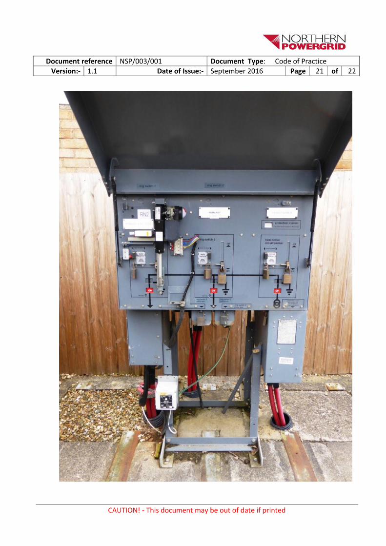
3.2.5. Outdoor Sites
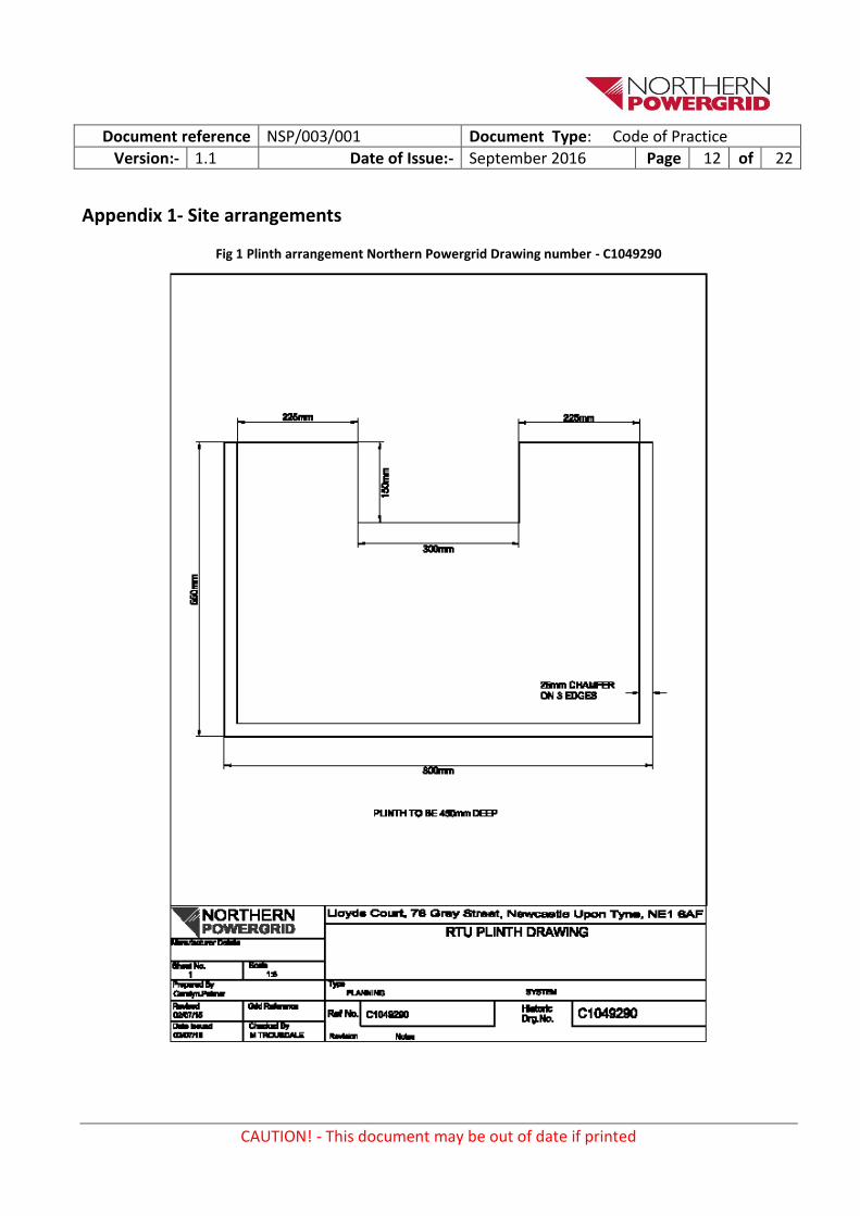
Consideration should be given to positioning of the RTU in outdoor situations so it is not positioned where it would assist as a climbing aid for access or egress. If a concrete plinth exists in a suitable location then this shall be used to mount the RTU on a freestanding support. Where installation of a separate plinth is required then this shall be formed on site as per NPG drawing no. C1049290 (Included in Appendices). Underground cables laid in the ground shall be installed to Northern Powergrid document NSP/002 - and shall be installed in 125mm ducts. Excavations shall be carried out in accordance with HSG 47.
3.2.6. Commissioning
Utilising a laptop the RTU will be loaded with the correct configuration, software and the site ID configured.
- All points to be locally tested. - All points remotely tested. - Actuator operation tested locally. - Actuator operation tested remotely. - Fault Passage Indicator to be tested and proved with control. - Move open point to respective switchgear and fit actuators. - Serial Numbers and test results to be recorded.
- A Commissioning pack will be left in the RTU cabinet which includes:
o Commission checklist sheet. o History sheet. o Actuator installation instructions. o A diagram detailing the function, location, rating, characteristics and type of all fuses, links
and terminations o A basic cabinet lay out diagram o A diagram/picture labelling all indication lights o Operation instructions for the associated actuators o Basic instructions that can be used by a non-specialist network operator using the local RTU.
These shall include: local/remote selection, actuator operation, isolation, locking, labelling and simple checks, diagnostics and rectifications.
3.2.7. Asset Information Recording and reporting
Throughout the planning and commissioning stages it will be necessary to amend drawings and asset data records, create IO pack/information and collate associated information as required. On completion of a scheme, Northern Powergrid asset records and diagrams will have been updated throughout, and handover pack as defined in Section 3.11 of the Technical Specification NPS/003/017 should be submitted to the Company.
Document reference NSP/003/001 Document Type: Code of Practice
Version:- 1.1 Date of Issue:- September 2016 Page 10 of 22
CAUTION! - This document may be out of date if printed
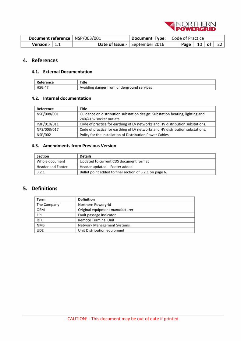
4. References
4.1. External Documentation
Reference Title
HSG 47 Avoiding danger from underground services
4.2. Internal documentation
Reference Title
NSP/008/001 Guidance on distribution substation design: Substation heating, lighting and 240/415v socket outlets
IMP/010/011 Code of practice for earthing of LV networks and HV distribution substations.
NPS/003/017 Code of practice for earthing of LV networks and HV distribution substations.
NSP/002 Policy for the Installation of Distribution Power Cables
4.3. Amendments from Previous Version
Section Details
Whole document Updated to current CDS document format
Header and Footer Header updated – Footer added
3.2.1 Bullet point added to final section of 3.2.1 on page 6.
5. Definitions
Term Definition
The Company Northern Powergrid
OEM Original equipment manufacturer
FPI Fault passage indicator
RTU Remote Terminal Unit
NMS Network Management Systems
UDE Unit Distribution equipment
Document reference NSP/003/001 Document Type: Code of Practice
Version:- 1.1 Date of Issue:- September 2016 Page 11 of 22
CAUTION! - This document may be out of date if printed
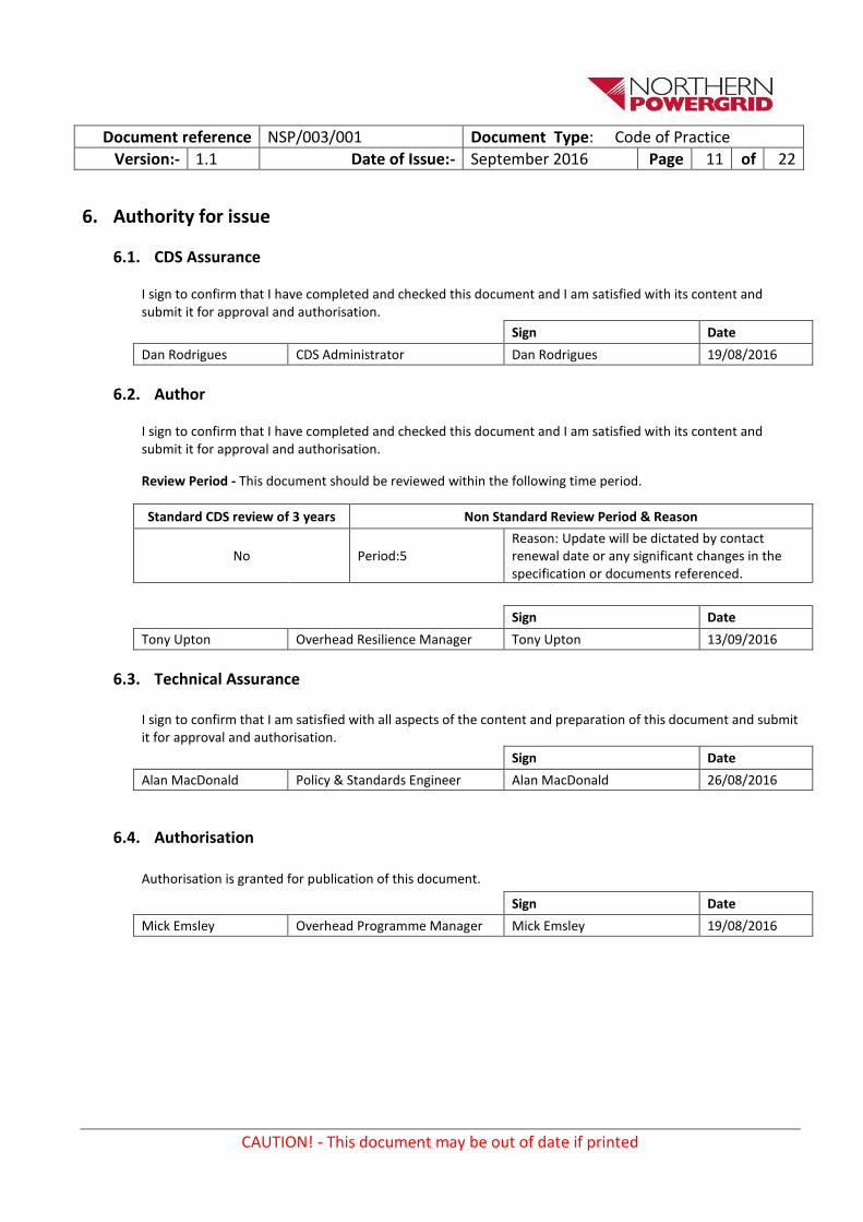
6. Authority for issue
6.1. CDS Assurance
I sign to confirm that I have completed and checked this document and I am satisfied with its content and submit it for approval and authorisation.
Sign Date
Dan Rodrigues CDS Administrator Dan Rodrigues 19/08/2016
6.2. Author
I sign to confirm that I have completed and checked this document and I am satisfied with its content and submit it for approval and authorisation.
Review Period - This document should be reviewed within the following time period.
Standard CDS review of 3 years Non Standard Review Period & Reason
No Period:5 Reason: Update will be dictated by contact renewal date or any significant changes in the specification or documents referenced.
Sign Date
Tony Upton Overhead Resilience Manager Tony Upton 13/09/2016
6.3. Technical Assurance
I sign to confirm that I am satisfied with all aspects of the content and preparation of this document and submit it for approval and authorisation.
Sign Date
Alan MacDonald Policy & Standards Engineer Alan MacDonald 26/08/2016
6.4. Authorisation
Authorisation is granted for publication of this document.
Sign Date
Mick Emsley Overhead Programme Manager Mick Emsley 19/08/2016
Document reference NSP/003/001 Document Type: Code of Practice
Version:- 1.1 Date of Issue:- September 2016 Page 12 of 22
CAUTION! - This document may be out of date if printed
Appendix 1- Site arrangements
Fig 1 Plinth arrangement Northern Powergrid Drawing number - C1049290

Document reference NSP/003/001 Document Type: Code of Practice
Version:- 1.1 Date of Issue:- September 2016 Page 13 of 22
CAUTION! - This document may be out of date if printed
Fig 2 RTU Mounting Arrangement For GRP Substation Northern Powergrid Drawing number - C1049513

Document reference NSP/003/001 Document Type: Code of Practice
Version:- 1.1 Date of Issue:- September 2016 Page 14 of 22
CAUTION! - This document may be out of date if printed
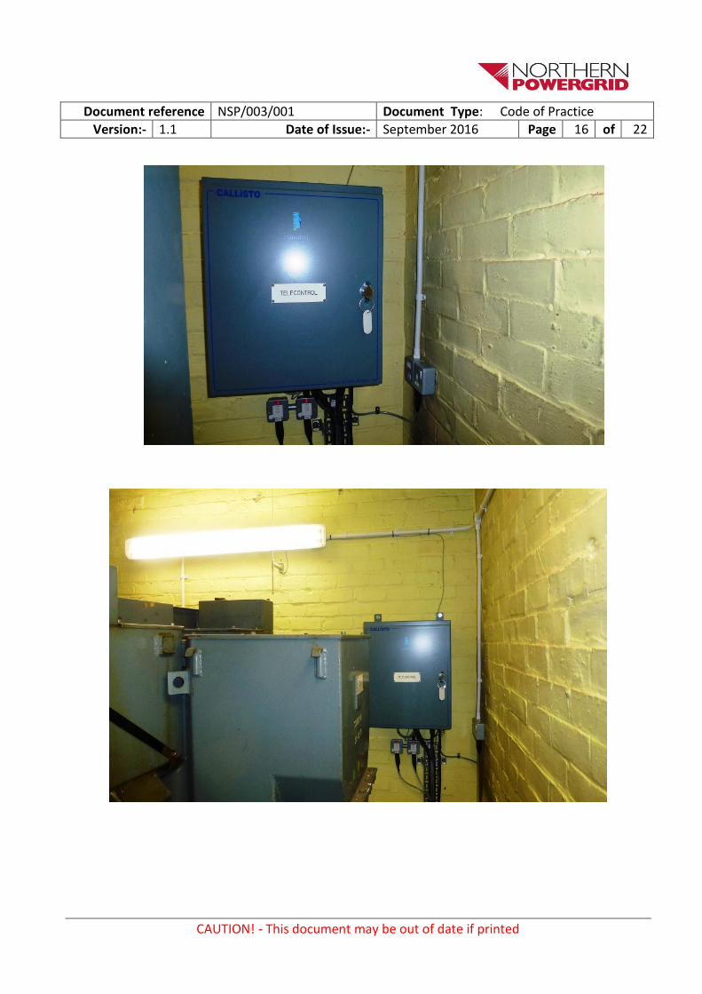
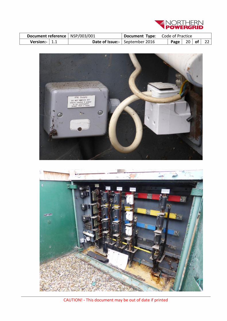
Pictures below show examples of existing arrangements

Document reference NSP/003/001 Document Type: Code of Practice
Version:- 1.1 Date of Issue:- September 2016 Page 15 of 22
CAUTION! - This document may be out of date if printed
Document reference NSP/003/001 Document Type: Code of Practice
Version:- 1.1 Date of Issue:- September 2016 Page 16 of 22
CAUTION! - This document may be out of date if printed

Document reference NSP/003/001 Document Type: Code of Practice
Version:- 1.1 Date of Issue:- September 2016 Page 17 of 22
CAUTION! - This document may be out of date if printed

Document reference NSP/003/001 Document Type: Code of Practice
Version:- 1.1 Date of Issue:- September 2016 Page 18 of 22
CAUTION! - This document may be out of date if printed

Document reference NSP/003/001 Document Type: Code of Practice
Version:- 1.1 Date of Issue:- September 2016 Page 19 of 22
CAUTION! - This document may be out of date if printed
Document reference NSP/003/001 Document Type: Code of Practice
Version:- 1.1 Date of Issue:- September 2016 Page 20 of 22
CAUTION! - This document may be out of date if printed
Document reference NSP/003/001 Document Type: Code of Practice
Version:- 1.1 Date of Issue:- September 2016 Page 21 of 22
CAUTION! - This document may be out of date if printed

Document reference NSP/003/001 Document Type: Code of Practice
Version:- 1.1 Date of Issue:- September 2016 Page 22 of 22
CAUTION! - This document may be out of date if printed