ntshengedzeni sampson mamphweli and edson leroy meyer · ntshengedzeni sampson mamphweli and edson...
TRANSCRIPT

In: Gasification: Chemistry, Processes and Applications ISBN: 978-1-61209-681-0 Editor: Michael D. Baker © 2012 Nova Science Publishers, Inc.
Chapter 10
COMPONENTS AND OPERATION OF THE FIXED BED DOWNDRAFT SYSTEM JOHANSSON BIOMASS
GASIFIER Ntshengedzeni Sampson Mamphweli∗ and Edson Leroy Meyer
University of Fort Hare, Institute of Technology, Private, Alice, South Africa
INTRODUCTION The chapter presents a detailed description of the System Johansson Biomass Gasifier
and its operation; it also deals with the factors influencing the efficiency of fixed bed biomass gasifier systems since the latter gasifier is a fixed bed type. Basically, the fuel is fed into the reactor where the gasification process takes place resulting in the formation of syngas. Syngas is channeled through a system of pipes to the downstream processes that consists mainly of the purification unit where it is cleaned of impurities such as fine carbon particles. The gas is then used to drive the engine that drives the generator and generates electricity. The gasifier is mainly used for electricity generation. A 150kVA pilot project aimed at improving the socio-economic status of a rural community has been implemented. The project aims to provide low-cost electricity to stimulate the establishment of small businesses in the area. Figure 1 shows the components of the gasifier.
∗ e-mail:[email protected]
The exclusive license for this PDF is limited to personal website use only. No part of this digital document may be reproduced, stored in a retrieval system or transmitted commercially in any form or by any means. The publisher has taken reasonable care in the preparation of this digital document, but makes no expressed or implied warranty of any kind and assumes no responsibility for any errors or omissions. No liability is assumed for incidental or consequential damages in connection with or arising out of information contained herein. This digital document is sold with the clear understanding that the publisher is not engaged in rendering legal, medical or any other professional services.

Figure 1. Schematic diagram of the gasifier.
Clean gas flare Gasifi
er
Gas scrubbe
Sawdust filter
Gas engine Sawdust filter
Cooling
Cyclone Condensate tank
Raw gas
Generator
Safety filter
Components and Operation of the Fixed Bed Downdraft System ... 297
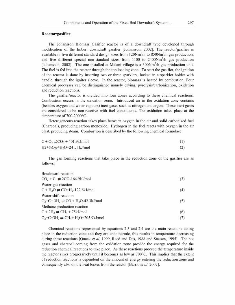
Reactor/gasifier The Johansson Biomass Gasifier reactor is of a downdraft type developed through
modification of the Imbert downdraft gasifier [Johansson, 2002]. The reactor/gasifier is available in five different standard design sizes from 120Nm3/h to 850Nm3/h gas production, and five different special non-standard sizes from 1100 to 2400Nm3/h gas production [Johansson, 2002]. The one installed at Melani village is a 300Nm3/h gas production unit. The fuel is fed into the reactor through the top loading zone. To start the gasifier, the ignition of the reactor is done by inserting two or three sparklers, locked in a sparkler holder with handle, through the igniter sleeve. In the reactor, biomass is heated by combustion. Four chemical processes can be distinguished namely drying, pyrolysis/carbonization, oxidation and reduction reactions.
The gasifier/reactor is divided into four zones according to these chemical reactions. Combustion occurs in the oxidation zone. Introduced air in the oxidation zone contains (besides oxygen and water vapours) inert gases such as nitrogen and argon. These inert gases are considered to be non-reactive with fuel constituents. The oxidation takes place at the temperature of 700-2000°C.
Heterogeneous reaction takes place between oxygen in the air and solid carbonized fuel (Charcoal), producing carbon monoxide. Hydrogen in the fuel reacts with oxygen in the air blast, producing steam. Combustion is described by the following chemical formulae: C + O2 CO2 + 401.9kJ/mol (1) H2+½O2 H2O+241.1 kJ/mol (2)
The gas forming reactions that take place in the reduction zone of the gasifier are as
follows:
Boudouard reaction CO2 + C 2CO-164.9kJ/mol (3) Water-gas reaction C + H2O CO+H2-122.6kJ/mol (4) Water shift reaction O2+C+ 3H2 CO + H2O-42.3kJ/mol (5) Methane production reaction C + 2H2 CH4 + 75kJ/mol (6) O2+C+3H2 CH4+ H2O+205.9kJ/mol (7)
Chemical reactions represented by equations 2.3 and 2.4 are the main reactions taking
place in the reduction zone and they are endothermic, this results in temperature decreasing during these reactions [Quaak et al, 1999, Reed and Das, 1988 and Stassen, 1995]. The hot gases and charcoal coming from the oxidation zone provide the energy required for the reduction chemical reactions to take place. As these reactions proceed the temperature inside the reactor sinks progressively until it becomes as low as 700°C. This implies that the extent of reduction reactions is dependent on the amount of energy entering the reduction zone and consequently also on the heat losses from the reactor [Barrio et al, 2007].

Ntshengedzeni Sampson Mamphweli and Edson Leroy Meyer
298
Carbonization is the thermal decomposition of biomass fuels in the presence of 26-30% of oxygen at temperature ranging from 450°C to 600°C. This process results in the release of charcoal, organic vapours and gasses [van de Beld, 2004 and Oregon Department of Energy, 2004]. The ratio of products is influenced by the chemical composition of biomass fuels and the operating conditions of the gasifier. Yields of primary carbonization products depend on temperature. For instance charcoal yield decreases and the gas yield increases with temperature [van de Beld, 2004]. This is because the charcoal is converted to gas, but at extremely high temperature the gas formed gets combusted resulting in low gasifier efficiency as explained in this chapter.
The heating value of gas produced during the gasification process is low (4-6 MJ/Nm3), or about 10% to 15% of the heating value of natural gas [Stassen, 1995].
Automatic variable speed ash grate activator The gasifiers are fitted with an automatic variable speed ash grate activator and with ash
removal and refueling systems for non-interrupted, continuous working. They are also supplied with electronic fuel level indicators and with an early refueling warning system. An electronic flashing red light ash removal warning system is also provided [Johansson, 2002]. This allows for a smooth uninterrupted 24 hours operation.
The cyclone The raw gas is passed through the cyclone, which removes the coarse carbon particles
from the raw gas. When operating at full gasifier/engine power, the conventional fixed cyclone removes about 80% of the carbon particles and soot, or about 4g/m3 of gas, leaving the remaining about 20% fine carbon and soot particles or about 1g/m3 of gas and this is carried through to the gas scrubber/cooler. If the power output is reduced, the cyclone starts to lose efficiency [Johansson, 2002]. This is basically because of the reduced centrifugal forces as explained later in this section.
The SJBG cyclone is a conventional cyclone. Typically, a particulate-laden gas enters tangentially near the top of the cyclone. The gas flow is forced into a downward spiral simply because of the cyclone’s shape and the tangential entry. Another type of cyclone (a vane axial cyclone) employs an axial inlet with fixed turning vanes to achieve a spiraling flow. Centrifugal forces and inertia cause the particles to move outward, collide with the outer wall, and then fall downward to the bottom of the device. Near the bottom of the cyclone, the gas reverses its downward spiral and moves upward in a smaller inner spiral. The cleaned gas exits from the top through a vortex finder tube, and the particles exit from the bottom of the cyclone through a pipe sealed by a spring-loaded flapper valve or rotary valve [Cooper and Alley, 1986 and Gradon et al, 1998]. The clean gas exiting the cyclone is termed the overflow while the retained particles collected at the bottom are termed the underflow.
The collection efficiency of cyclones vary with particle size and cyclone design. The efficiency of particle collection is generally good for particles that are larger than 5 microns. Other cyclones have collection efficiency greater than 98% for particles larger than 5 microns

Components and Operation of the Fixed Bed Dowdraft System …
299
and others do achieve efficiencies of 90% for particles larger than 15-20 microns [Cooper and Alley, 1986 and Gradon et al, 1998]. High efficiency requires higher inflow pressure. Three categories of cyclones are available and these are the high efficiency, conventional and high throughput. The high efficiency attains a higher efficiency followed by the conventional and high throughput respectively.
The cyclone performance is rated in terms of particle cut diameter (dp) or cut size. The cut size, Dp50 for instance is the particle size which is captured 50% [Reed and Das, 1988]. The impact of particle size on collection efficiency is quantified in the following section.
Cyclone collection Efficiency model A model can be used to determine the effects of both cyclone design and operation on
collection efficiency. In this model, gas spins through a number of revolutions Ne in the outer vortex. The value of Ne can be approximated by [Cooper and Alley, 1986]:
⎟⎠⎞
⎜⎝⎛ +=
21 c
beL
LH
N (8)
where:
eN = number of effective turns H = height of inlet duct (m) Lb = length of cyclone body (m) Lc = length (vertical) of cyclone cone (m).
Figure 2 shows the various dimensions of the cyclone for better understanding of the
equations. To be collected, particles must strike the wall within the amount of time that the gas
travels in the outer vortex. The gas residence time in the outer vortex is
i
e
VDN
tπ
=Δ (9)
where:
Δt = time spent by gas during spiraling descent (sec) D = cyclone body diameter (m) Vi = gas inlet velocity (m/s) = Q/WH Q = volumetric inflow (m3/s)

Ntshengedzeni Sampson Mamphweli and Edson Leroy Meyer
300
Figure 2. Various dimensions of the cyclone.
The maximum radial distance travelled by any particle is the width of the inlet duct (W). The centrifugal force quickly accelerates the particle to its terminal velocity in the outward (radial) direction, with the opposing drag force equaling the centrifugal force.
The terminal velocity Vt of the particle in a radial direction that will just allow a particle initially at distance (W) away from the wall to be collected in time Δt is
tWVt Δ
= (10)
where
W = width of inlet (m). Vt = particle terminal velocity in the radial direction (m/s).
In addition Vt is a function of particle size. Assuming Stokes’ regime flow (drag force =
3πμdpVt) and spherical particles subjected to a centrifugal force F.
F=mv2/r (11) where:
m = mass of particle in excess of mass of gas displaced v = Vi of inlet flow, and r =D/2= radius
We obtain:
H
W
D
S
Lb
Lc
D
Dd

Components and Operation of the Fixed Bed Dowdraft System …
301
( )D
VdV ipgp
t μρρ
9
22−=
(12) where
dp = diameter of the particle (m) ρp = density of the particle (kg/m3) ρg= gas density (kg/m3) μ = gas viscosity (kg/m.s).
The density and viscosity values of air and syngas are similar, since most of syngas
constituents are similar to air (CO, N2, and to a lesser extent CO2). Only the hydrogen portion is substantially great in syngas.
Substitution of equation 2.9 into the 2.10 eliminates Δt. Then, equating 10 and 12 and rearranging to solve for particle diameter, we obtain [Cooper and Alley, 1986]:
( )2
1
9⎥⎥⎦
⎤
⎢⎢⎣
⎡
−=
gpiep VN
Wdρρπ
μ
(13) It is worth noting that in this expression, dp is the size of the smallest particle that will be
collected if it starts at the inside edge of the inlet duct. Thus, in theory, all particles of size dp or larger should be collected with 100% efficiency [Cooper and Alley, 1986].
There are three factors that determine the centrifugal force; these are radius of spiral motion, particle mass, and particle velocity. The relationship between these factors and the centrifugal force can be described by equation 11. In equation 11, increasing the velocity of the particle (V) and/or decreasing the radius of the vortex flow (r) can increase the efficiency of separation [Holley et al, 2006]. However care should be taken when decreasing the size of the vortex finder as this might results in low gas flow rates impacting negatively on the efficiency of the engine as it will have to apply more power in sucking the gas.
The gas scrubber/cooler After the coarse dust has been removed in the cyclone, about 0.8g/m3 gas is removed in
the gas scrubber/cooler, where the gas is cooled to between 20°C to 25°C with water sprayed over a suitable low resistance, large surface area scrubbing media (charcoal). The water is normally recycled through an ambient cooling pond for a long period of time [Johansson, 2002b].
Particles larger than 1µm settle by gravity and inertia in accordance with Stoke’s law and can be captured by impaction, gravitational or centrifugal means. For particles smaller than 0.1µm, motion is dominated by molecular collisions in accordance with Brownian motion principles. These particles may be collected by diffusion onto a liquid surface. Particles with diameters between 0.1 and 1µm are the most difficult to capture either by diffusion or inertial mechanisms. They are too large to diffuse well but too small to settle, however they

Ntshengedzeni Sampson Mamphweli and Edson Leroy Meyer
302
can be made to agglomerate into larger particles that are easier to collect. Agglomeration is also assisted by the presence of droplets that act as nuclei [Reed and Das, 1988].
Particles tend to move towards a surface on which condensation is taking place. This phenomenon is referred to as Stefan motion. Particles tend to migrate away from a hot surface towards a cold surface, this phenomenon is called thermophoresis. Wetted particles tend to stick together when they collide, thereby assisting agglomeration [Reed and Das, 1988]. At the gas scrubber, the gas enters at high temperature (approximately 500°C); the gas is cooled to room temperature (approximately 25°C) before it exits the scrubber. The condensable part of the gas (water vapour) reaches dew point temperature and condenses against the charcoal and walls of the scrubber. Therefore particles will move towards these two surfaces where condensation will be taking place. The particles entering with hot gas will also move towards the cold surface in the wet scrubber enhancing their collection efficiency.
Wet scrubbing requires that the water remain in the liquid phase, which requires that the syngas be cooled to below 100°C. This loss of heat may be undesirable in some systems. Most biomass gasification systems that currently use wet scrubbers do so primarily as a means to remove tars rather than particulates from the gas stream. Removing the particulates separately can prevent condensation of the sticky tars on the particulate surface, which further prevents fouling and plugging of filter surfaces. Figure 3 shows the packed bed gas scrubber used in the System Johansson Biomass Gasifier.
Figure 3. The packed bed scrubber.
Long life particle interference sawdust filters
Water out
Clean gas out
Dirty gas in
Sprays
Charcoal bed
Water in

Components and Operation of the Fixed Bed Dowdraft System …
303
After the gas cooler/scrubber, the cooled gas is passed through the long life filters, filled with particle interference sieved course sawdust filter media, where the remaining very fine non-wettable lampblack carbon dust of about 0.2g or 1g/m3 gas is absorbed [Johansson, 2002]. This filters the fine carbon particles through adsorption. Engine safety filters
Before the engine, the clean gas is finally passed through a standard 5 micron double
cartridge Donaldson air filter, modified as safety gas filter with much reduced flow capacity. It is provided with a special gas-tight purpose-made seal between the dust bowl and the filter body [Johansson, 2002].
Gas engine Figure 4 shows the gas engine that is powered by syngas to drive a 150kVA synchronous
generator to produce electricity.
Figure 4. The gas engine coupled to a 150kVA synchronous generator.
The classical control principle of the large power synchronous generators with excitation winding is well known [Burth et al, 1999, Fard et al, 2005, Karrari, and Menhaj, 2000, IEEE Std 1110-2002, 2003, Karrari, and Malik, 2004, Karayaka, 2003, Melgoza et al, 2001,

Ntshengedzeni Sampson Mamphweli and Edson Leroy Meyer
304
Shamsollahi and Malik , 1996, Stefopoulos et al, 2005, Venayagamoorthy, and Harley, 2000, and Wright, 1931], considering the frequency and voltage control by means of the active (P) and reactive power (Q) adjustment, respectively. The two control loops are usually operating separately from each other. Consequently, it may be considered as a scalar control (SC) procedure, which disregards some fundamental phenomena, i.e. the coupling effect inside the synchronous generator [Kelemen and Imecs, 1990, Kelemen and Imecs, 1993, and Kelemen and Imecs, 1989].
FACTORS INFLUENCING THE EFFICIENCY OF FIXED BED BIOMASS GASIFIER SYSTEMS
Definition of gasifier efficiency
Reactor efficiency
The average energy conversion efficiency of wood gasifiers is about 60-70% and is defined as:
s
g
HH
=η (14)
where:
η is the gasification efficiency (%) Hg is the higher heating value of syngas (MJ/m3), Hs is the average Higher Heating value of fuel (MJ/kg) [Rajvanshi, 1986].
If the gas is used for engine applications the gasification efficiency is defined as follows:
%100××
×=
ss
ggm MH
QHη
(15) where:
ηm = gasification efficiency (%) (Mechanical) Hg = higher heating value of the syngas (kJ/m³), Qg = volume flow of syngas (m³/s) Hs = lower heating value of gasifier fuel (MJ/kg) Ms = gasifier solid fuel consumption (kg/s)

Components and Operation of the Fixed Bed Dowdraft System …
305
If the gas is used for direct burning, the gasification efficiency is sometimes defined as [Food and Agricultural Organization, 1986]:
%100()(
××
Δ×××+×=
ss
pggggth MH
TCQQH ρη
(16) where:
ηth = gasification efficiency (%) (thermal) ρg = density of the gas (kg/m³) Cp = specific heat of the gas (kJ/kg°C) ∆T = temperature difference between the gas at the burner inlet and the fuel entering the gasifier (°C).
Depending on the type and design of the gasifier as well as on the characteristics of the
fuel mechanical efficiency may vary between 60 and 75% whereas the thermal efficiency can be as high as 93% [Food and Agricultural Organization, 1986].
Co-generative efficiency
The electrical efficiency of the gasifier power plant depends on the efficiency of engine/ generators. This can be defined as:
bm
netep HHV
EP=η
(17) where
ηep= Electrical power efficiency EPnet= Net electrical power HHVbm= High heating value of biomass materials utilized.
The co-generative efficiency of the biomass power plant can be defined as:
bm
netthermalcg HHV
EPP +=η
(18) where:
ηcg= Co-generative efficiency/overall power plant efficiency Pthermal= Thermal power [Fermeglia et al, 2008].
The co-generative efficiency of the power plant depends on the efficiency of the gasifier and that of the engines/generators.

Ntshengedzeni Sampson Mamphweli and Edson Leroy Meyer
306
Impact of gasifier/reactor design on efficiency
There are a number of gasifier designs; each gasifier design has its advantages and
disadvantages. Attention will be given to fixed bed gasifiers, which are updraft, downdraft and crossdraft gasifiers.
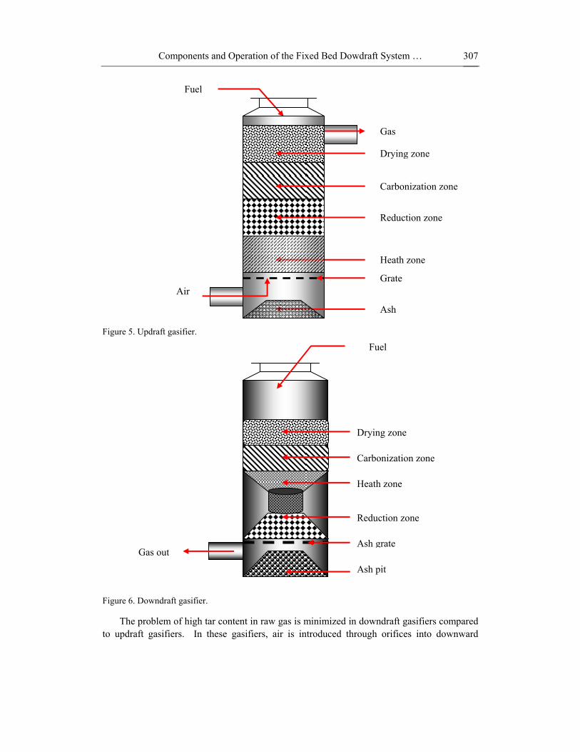
An updraft gasifier has clearly defined zones for partial combustion/oxidation, reduction and carbonization. Figure 5 shows a diagram of the updraft gasifier. The feedstock is introduced at the top and air is introduced at the bottom and acts as countercurrent to fuel flow. The gas is drawn at the top of the gasifier. The updraft gasifier achieves the highest thermal efficiency as the hot gas passes through the fuel bed and leaves the gasifier at low temperature of around 200–300°C. The sensible heat given off by the gas is used to preheat and dry the fuel; as a result wet biomass up to 50% moisture content can still be gasified without any pre-drying. The disadvantages of this type of gasifier are excessive tar in the raw syngas and poor loading capacity. The tar can interfere negatively with the operation of internal combustion engines. This makes this gasifier not a likely candidate for power applications [Quaak et al, 1999, Rajvanshi, 1986 and Mckendry, 2002]. Large quantities of liquid effluents are produced in updraft gasifiers, the liquid effluent can be highly toxic and their disposal can pose environmental and health hazards. Additional study is needed on treatment options for these liquid fuels [Stassen, 1995]. The tar and condensates contains a certain proportion of energy that leaves the gasifier without converted to useful form, there is need to quantify the amount of energy leaving this type of gasifier with tar and condensates to establish its impact on the energy and mass balance of the gasifier.
The higher efficiency that the updraft gasifier type can achieve is due to low exit gas temperature. Considering the fact that some of the energy is lost during tar removal this gasifier efficiency could be overestimated when compared to the other gasifier types. The internal energy usage in the drying of fuel results in higher condensates quantities; the condensates contain chemical energy which is lost during their removal, this energy lost also needs to be quantified.
Updraft gasifiers can be scaled up while the maximum size of downdraft gasifier is probably limited to 1MWe [Mckendry, 2002] because of the uneven distribution of the gasification agent around the large gasifier throat, leading to uneven heat distribution and excessive tar production. However, for electricity generation applications, the very high level of tars in the product gas must be greatly reduced prior to the internal combustion engine to avoid problems of deposition and ultimate blockage. In the Wellman configuration studied by Brammer and Bridgewater, this is achieved by two stage cracking of the tar-laden gas, first thermally in an air-fired secondary oxidation reactor and finally in a catalytic cracker [Brammer and Bridgewater, 2002].
Components and Operation of the Fixed Bed Dowdraft System …
307
Figure 5. Updraft gasifier.
Figure 6. Downdraft gasifier.
The problem of high tar content in raw gas is minimized in downdraft gasifiers compared to updraft gasifiers. In these gasifiers, air is introduced through orifices into downward
Drying zone
Carbonization zone
Heath zone
Reduction zone
Ash grate
Ash pit
Fuel
Gas out
Grate
Heath zone
Reduction zone
Ash
Gas
Fuel
Drying zone
Carbonization zone
Air

Ntshengedzeni Sampson Mamphweli and Edson Leroy Meyer
308
flowing packed bed or solid fuels at the oxidation zone and gas is drawn off at the bottom. The gases leave the gasifier after passing through the hot zone, enabling the partial cracking of the tars formed during gasification and giving a gas with low tar content. The disadvantage of the downdraft gasifier is a lower overall efficiency because gases leave the gasifier unit at temperatures about 900–1000°C [Food and Agricultural Organization, 1986 and Rajvanshi, 1986]. The thermal energy in the exit gas need to be extracted and utilized in downstream processes to improve the efficiency of gasification systems using this type of gasifier. Figure 6 shows the downdraft gasifier.
The downdraft gasifier also experiences difficulties in handling higher moisture contents in fuel; typically requires fuel with maximum 20% moisture content. Higher ash contents pose problems in small downdraft gasifiers. The time (20-30 minutes) needed to ignite and bring the plant to working temperature with good gas quality (4-6MJ/kg) is shorter than in updraft gas producers. This gasifier is preferred to updraft gasifier for internal combustion engines [Beeneckers, 1999] because of low levels of tar in the final gas.
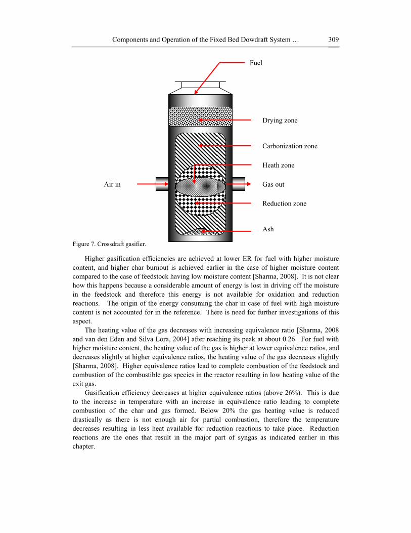
In a crossdraft gasifier the feedstock moves downwards while the air is introduced from the side, the gas is withdrawn from the opposite side of the unit at the same level. A hot combustion/gasification zone forms around the entrance of the air; with the pyrolysis and drying zones being formed at the top section of the gasifier. Ash is removed at the bottom and the temperature of the gas leaving the unit is about 800–900°C; as a consequence this gives low overall energy efficiency for the process like in downdraft gasifier and a gas with high tar content like in updraft gasifier [Mckendry, 2002]. Figure 7 shows a diagram of the crossdraft gasifier.
These design characteristics limit the type of fuel for operation to low ash fuels such as wood, charcoal and coke. The startup time (5-10 minutes) is much faster than that of updraft and downdraft gasifiers. The relatively high temperature in crossdraft gasifiers has an effect on gas composition such as high carbon monoxide, and low hydrogen and methane content when dry fuels such as charcoal is used. These types of gasifiers operate well on dry fuel [Tripod, 2006], which is normally hard to find and mostly processed from wet fuel through drying.
Impact of equivalence ratio on gasifier efficiency Equivalence Ratio (ER) is a measure of the amount of external oxygen (or air) supplied
to the gasifier. ER is obtained by dividing the actual oxygen (or air) to biomass molar ratio to the stoichiometric oxygen (or air) to biomass molar ratio. Oxygen is generally supplied as a gasifying and fluidizing medium. Using air in place of oxygen though economical has the negative effect of diluting the syngas due to the presence of nitrogen. Madhukar et al [2007] conducted simulations to investigate the impact of ER on equilibrium composition for operating conditions of Temperature (T) = 827°C and moles of steam supplied per mole of biomass (β) =0. They established that higher ER results in reduced CO and H2 yield while that of CO2 increases, this is due to the oxidation of H2 and CO to H2O and CO2. At low values of ER, small amounts of solid carbon (C(s)) and CH4 are formed in the gasifier, both of which get oxidized as more air is supplied.
Components and Operation of the Fixed Bed Dowdraft System …
309
Figure 7. Crossdraft gasifier.
Higher gasification efficiencies are achieved at lower ER for fuel with higher moisture content, and higher char burnout is achieved earlier in the case of higher moisture content compared to the case of feedstock having low moisture content [Sharma, 2008]. It is not clear how this happens because a considerable amount of energy is lost in driving off the moisture in the feedstock and therefore this energy is not available for oxidation and reduction reactions. The origin of the energy consuming the char in case of fuel with high moisture content is not accounted for in the reference. There is need for further investigations of this aspect.
The heating value of the gas decreases with increasing equivalence ratio [Sharma, 2008 and van den Eden and Silva Lora, 2004] after reaching its peak at about 0.26. For fuel with higher moisture content, the heating value of the gas is higher at lower equivalence ratios, and decreases slightly at higher equivalence ratios, the heating value of the gas decreases slightly [Sharma, 2008]. Higher equivalence ratios lead to complete combustion of the feedstock and combustion of the combustible gas species in the reactor resulting in low heating value of the exit gas.
Gasification efficiency decreases at higher equivalence ratios (above 26%). This is due to the increase in temperature with an increase in equivalence ratio leading to complete combustion of the char and gas formed. Below 20% the gas heating value is reduced drastically as there is not enough air for partial combustion, therefore the temperature decreases resulting in less heat available for reduction reactions to take place. Reduction reactions are the ones that result in the major part of syngas as indicated earlier in this chapter.
Drying zone
Fuel
Reduction zone
Ash
Carbonization zone
Heath zone
Air in Gas out
Ntshengedzeni Sampson Mamphweli and Edson Leroy Meyer
310
Mathieu and Dubuisson [2002] investigated the impact of ER on the gas composition; they established that the composition of the gas changes with ER. The variations of the various gas species versus ER are more or less linear. N2 and H2O increase with ER from 35% up to 53% and from 5% up to 15% respectively. CO and H2 decrease from 28% down to 15% and from 21% to 7% respectively. CO2 remains fairly constant (10%) whilst CH4 remains almost close to zero in the range 20-50% of ER.
The variation in the gas composition with ER is in line with the findings by Sharma [2008] and van den Eden and Silva Lora [2004] that the efficiency increases with ER until it reaches its peak at 26% and starts to decrease. This is basically because of the changes in gas compositions as the efficiency is dependent on the volume and composition of the gas.
Impact of pressure on gasifier efficiency Altafini et al [2003] carried out simulations to establish the impact of pressure on gas
compositions through the equilibrium model. They reported that the increase in pressure results in reduced hydrogen and carbon monoxide volumes. They also established that very low pressures (10.13kPa) results in an increase in the yield of H2, however the increase was found to be neglible (less than 0.2%). Low pressure does not provide substantial improvements and high pressure reduces H2 yield. Atmospheric pressure is the best condition for fixed bed gasifiers.
Impact of fuel properties on gasifier efficiency A study was undertaken to establish the impact of fuel properties on gasification.
Wyodak coal and cellulose (which accounts for half the weight of biomass) were used to conduct the study. A pyrolysis experiment was conducted. Nearly complete de-volatilization of cellulose was found to occur below 500°C. In contrast, only about 40% of coal was de-volatilized and only after heating to close to 900°C. The slower weight loss with coal reflects its inherently lower thermochemical reactivity and the much higher fraction of weight remaining even after heating to 900°C reflects the much lower content of volatile components in coal compared to cellulose. The remaining char was gasified [Williams and Larson, 1996].
Char gasification is one of the major processes involved in converting solid fuels into
combustible gases. Because of the higher reactivity of biomass chars, these gasify much more rapidly and at lower temperatures than coal chars. Thus, lower temperatures can be used in biomass gasifiers compared to coal gasifiers to achieve the same level of char conversion to gas [Williams and Larson, 1996].
Higher ash or moisture content results in lower conversion efficiency [Faaij et al, 1997]. There is an increase in conversion efficiency with a decrease in moisture content. This is because a high quantity of energy is consumed during the drying process and the energy is no longer available for reduction reactions [Jayah et al, 2003] mentioned earlier in this chapter. Effect of air temperature on efficiency

Components and Operation of the Fixed Bed Dowdraft System …
311
Air pre-heating has a positive impact on gasification efficiency, the high air inlet temperature (Ta) results in higher gasification efficiency as the sensible heat brought into the reactants induces an increase in reaction temperature (Tr). Mathieu and Dubuisson [2002] conducted an experiment to investigate the impact of air pre-heating on gasification efficiency. The reaction temperature was found to increase from 775°C up to 1025°C when air inlet temperature (Ta) increases from 25°C up to 800°C. Gasification efficiency increases with air inlet temperature significantly from 76.6% up to 79.5% when the feeding air is preheated from 25°C up to 300°C. Beyond 300°C, gasification efficiency still increases but only slightly from 79.5% to 80.1% when Ta goes up from 300°C to 825°C. The composition of the gas varies and the corresponding heating value is 5169 kJ/kg fuel when the air is at 25°C and increases up to 5402 kJ/kg with the air at 800°C [Mathieu and Dubuisson, 2002].
All these evolutions can be explained by the following conflicting trends:
• The CH4 production from C and H2 being exothermic is decreased when Tr and hence Ta increase;
• The consumption of CH4 in endothermic reactions with H2O and CO2 is increased when Tr and hence Ta increase;
• The shift reaction CO + H2O CO2 + H2 being exothermic, water and CO consumption decrease when the temperature increases;
• The Boudouard reaction is endothermic, CO production increases at the expense of carbon and CO2 when the temperature increases [Mathieu and Dubuisson, 2002].
High temperature air increases gasification yields leading to high gasification
efficiencies. Zubtsov et al [2001] conducted an experiment with air pre-heated to 1000°C when gasifying Skyline coal, the resulting syngas was found to have a heating value of about 1400Kcal/m3; without the preheated air, only 850Kcal/m3 could be achieved. When ambient temperature air was used, the resulting low combustion temperature would prevent the reactions from reaching completion resulting in low heating value gases and low conversion efficiency [Zubtsov et al, 2001]; the same applies to gasification of biomass materials as indicated by Mathieu and Dubuisson [2002].
The gasification temperature not only affects the product yield but also governs the process energy input. High gasification temperature produces a gas mixture rich in H2 and CO with small amounts of CH4 and higher hydrocarbons. At low temperatures, solid carbon (C(s)) and CH4 are present in the syngas. Solid carbon is carried away and is deposited on the downstream processes. It is necessary to ensure that the syngas is free of any solid carbon. As temperature increases, both carbon and methane are reformed. At about 727°C both are reduced to very small amounts and in the process get converted into CO and H2. This explains the increase in hydrogen moles from 627°C to 757°C. At about 757°C, the H2 yield reaches a maximum value of about 1.33 mol. At still higher temperatures, the H2 yield starts reducing. This is attributed to the water–gas shift (WGS) reaction (equation 2.4). According to Le-Chatelier's principle, high temperature favors reactants in an exothermic reaction thus explaining the increase in CO and reduction in H2 (and CO2 yield) at higher temperature.

Ntshengedzeni Sampson Mamphweli and Edson Leroy Meyer
312
Hence, gasification temperature of about 757°C gives the highest equilibrium hydrogen yield with negligible solid carbon in the product gas [Madhukar et al, 2007].
CONCLUSION The fixed bed downdraft biomass gasifiers are preferred in electricity generation because
of their production of gas that has low tar content compared to their updraft and crossdraft counterparts. However the main problem with fixed bed downdraft gasifier systems is their low conversion efficiency due to their low charcoal burnout rate. The other challenge facing these gasifier types is the fact that they are limited in size; they cannot be scaled up for large scale project applications. The system Johansson Biomass gasifier is a downdraft gasifier system that can be applied in small scale for electricity generation purposes because of its production of tar-free gas. It can also be applied at medium scale in modular form.
REFERENCES
Altafini C. R. Paulo R. Wander and Ronaldo Barreto, M. Prediction of the working parameters of a wood waste gasifier through an equilibrium model, Energy Conversion and Management 44 (17), (2003), pp. 2763-2777.
Barrio, M. Fossum, M. Hustad J. E. (2007) A small-scale stratified downdraft gasifier coupled to a gas engine for combined heat and power production. Norwegian University of Science and Technology, Department of Thermal Energy and Hydro Power, 7491 Trondheim, Norway Sintef Energy Research, Department of Thermal Energy, 7465 Trondheim, Norway.
http://www.tev.ntnu.no/MariaBarrio/publikasjoner/article%20gasifier.pdf, Last accessed February 2007.
Beeneckers A. A. C. M. Biomass gasification in moving beds, a review of European technologies, Renewable energy 16 (1999), pp. 1180-1186.
Brammer J. G. and Bridgwater A. V. The influence of feedstock drying on the performance and economics of a biomass gasifier engine CHP system, Biomass and Bioenergy 22 (2002) (4), pp. 271-281.
Burth, M. Verghese G. C. and Velez-Reyes, M. Subset selection for improved parameter estimation in on-line identification of a synchronous generator, IEEE Trans. Power Syst. 14 (1) (1999), pp. 218–225.
Carbo Consult, 2008, http://www.carboconsult.com/fuel-compartment.asp, Last accessed October 2008.
Cooper, C. D. and Alley, F. C. (1986) Air Pollution Control: A Design Approach. Prospect Heights, Ill.: Waveland Press.
Faaij, A, van Ree, R. Waldheim, L. Olsson E. Oudhuis A. F. van Wijk, AD. Daey-ouwensll, C. and Turkenburg, W. Biomass and Bioenergy 12 (6) (1997), pp. 387-417.

Components and Operation of the Fixed Bed Dowdraft System …
313
Fard, R. D. Karrari, M. and Malik, O. P. Synchronous generator model identification for control application using Volterra series, IEEE Trans. Energy Convers. 20 (4) (2005), pp. 852–858
Food and Agricultural Organization. (1986) Wood gas as engine fuels. FAO forestry papers. http://www.fao.org/documents/show_cdr.asp?url_file=DOCREP/TO512eOb.htm. Last accessed May 2006.
Food and Agricultural Organization, FAO Forestry paper-72. (1986) Wood gas engine fuel, http://www.fao.org/documents/show_cdr.asp?url_file=/docrep/t0512e/T0512e09.htm, last visited, 29/05/2006.
Fermeglia, M. De Simon, G. Donald G. Energy production from biomass gasification by molten carbon fuel cells process simulation, proceedings of the International conference on Hydrogen Age, Palermo, Italy, 18-20 October 2005.
Gradon, L. Luckner, H. Podgorski, A. Wertejuk, Z. Separation of neutral and charged aerosol particles in cyclones with external electric field, Journal of Aerosol Science 29 (1998), pp S927-S928. IEEE Std 1110-2002, IEEE Guide for Synchronous Generator Modeling Practices and
Applications in Power System Stability Analysis, 2003, pp. 1–72. Jayah, T. H. Lu, A. Fuller, R. J and Stewart, D. F. Computer simulation of a downdraft wood
gasifier for tea drying, Biomass and Bioenergy 25 (4) (2003) 459-469. Johansson, K. G. (2002) System Johansson gas producers: Brief description of wood gas
producer system for tar free continuous gas generation. Midrand, South Africa. Unpublished document.
Johansson, K. G. (2002) (b) System Johansson gas producers: General description and operator’s instructions. Midrand, South Africa. Unpublished manual.
Karrari, M. and Menhaj, M. B. Application of different neural networks for identification of power systems, UKACC Conference on Control 2000 University of Cambridge, UK (2000).
Karrari, M. and Malik, O.P. Identification of physical parameters of a synchronous generator from on-line measurements, IEEE Trans. Energy Convers. 19 (2) (2004), pp. 407–415.
Karrari, M. and Malik, O. P. Identification of Heffron–Philips model parameters for synchronous generators using online measurements, IEE Proc. Gener. Transm. Distrib. 151 (3) (2004), pp. 313–320.
Karayaka, H. B. Keyhani, A. Heydt, G. T Agraval B. L. and Selin, D. A. Synchronous generator model identification and parameter estimation from operating data, IEEE Trans. Energy Convers. 18 (1) (2003), pp. 121–126
Kelemen Á, Imecs M: (1993) Vector Control of AC Drives, Vol. 2: Vector Control of Synchronous Machine Drives, Ecriture Publisher, Budapest.
Kelemen, Á. Imecs M. Vector control system for frequency and voltage of synchronous generators, Proceedings of International Conference on Electrical Machines, ICEM ‘90, (1990), Cambridge, Massachusetts, USA.
Kelemen, Á. Imecs M. Procedure and Driving Device for Unitary Automatic Vector Control of the Active and Reactive Power of Synchronous Generators by Means of Frequency and Voltage Regulation (in Romanian), Patent of Invention Nr. 104278/30.10.1989, Romania.

Ntshengedzeni Sampson Mamphweli and Edson Leroy Meyer
314
Kerekezi, S. and Ranja, T. (1997) Renewable energy technologies in Africa, Zed Books ltd. London, UK.
Madhukar, R. Mahishi, Y. and Goswami, D. Thermodynamic optimization of biomass gasifier for hydrogen production, International Journal of Hydrogen Energy 32 (16) (2007), pp. 3831-3840.
Mathieu, P. Dubuisson, R. Performance analysis of a biomass gasifier. Energy Conversion and Management 43 (2002), pp. 1291–1299.
Mckendry, P. Energy production from biomass (part3): gasification technologies, Bioresource Technology 83 (2002) (1), pp. 55-63.
Quaak, P. Knoef, H. and Stassen, H (1999) Energy from Biomass: A review of Combustion and Gasification Technologies, The World Bank, Washington DC, USA.
Rajvanshi A. K. (1986) Biomass Gasification., Published as chapter 4 in book: Goswami D.Y., Ed (1986), Alternative Energy in Agriculture Vol. II., CRC Press, pp 83-102. http://nariphaltan.virtualave.net/gasbook.pdf, last visited 11/11/ 2008.
Reed, T. B. and Das, A., (1988) Handbook of Biomass Downdraft Gasifier Engine Systems, SERI/SP-271-3022, UC Category: 245, Solar Energy Research Institute, 1617 Cole Boulevard, Golden, Colorado 80401-3393.
Stefopoulos, G. K. Georgilakis, P. S. Hatziargyriou N. D. and Sakis A. P. Meliopoulos, A genetic algorithm solution to the governor-turbine dynamic model identification in multi-machine power systems, IEEE Conference on Control Application Toronto, Canada (2005), pp. 245–250.
Stassen, H. E. (1995) Small-Scale Biomass Gasifiers for Heat and Power: A Global Review, World Bank Technical Paper No. 296, Energy series, World Bank, Washington DC, USA.
Sharma, A. K., Equilibrium and kinetic modeling of char reduction reactions in a downdraft biomass gasifier: A comparison, Solar Energy 82 (2008), pp 918–928.
Sharma, A. Kr. Equilibrium modeling of global reduction reactions for a downdraft (biomass) gasifier. Energy Conversion and Management 49 (4) (2008), pp. 832-842.
Tripod, Biomass Gasification: Technology and utilization, http://members.tripod.com/cturare/ his.htm, last visited, 29/05/2006.
van de Beld Ir. L, (2004) Flash pyrolysis. Biomass Technology Group. http://www. btgworld.com/technologies/pyrolysis.html, Last accessed on December 2006.
van den Enden, P. J. Silva Lora, E. B. Design approach for a biomass fed fluidized bed gasifier using the simulation software CSFB. Biomass and Bioenergy 26 (2004), pp. 281 – 287.
Williams, R.H. and Larson E. D. Biomass gasifier gas turbine power generating technology (1996) Biomass and Bioenergy 10 (2-3) (1996), pp. 149-166.
Wright, S. H. Determination of synchronous machine constants by test, AIEE Trans. 50 (1931), pp. 1331–1351.
Zubtsov, V.M., Pian, C.C.P., and Yoshikawa, K. Potential applications of high-temperature air/steam blown gasification and pyrolysis systems. Energy 30 (2005), pp. 2229-2242.