nuclear uav thesis
TRANSCRIPT

DESIGN OF A NUCLEAR PROPULSION SYSTEM FOR AN UNMANNED AERIAL
VEHICLE
By
Ronald David Turba
Thesis
Submitted to the Faculty of the
Graduate School of Vanderbilt University
in partial fulfillment of the requirements
for the degree of
MASTER OF SCIENCE
in
Mechanical Engineering
May, 2011
Nashville, Tennessee
Approved:
Dr. Alvin Strauss
Dr. George Cook

ii
DEDICATION
To my family and friends
Who not only celebrated my victories
But continued to have faith after my defeats
iii
ACKNOWLEDGMENTS
I would like to thank my advisor Dr Al Strauss for his guidance and support
throughout this project. His knowledge in the field and his professional colleagues
helped me get through many obstacles. I would like to thank Dr Steve Howe of Idaho
National Laboratory for his knowledge and research of nuclear fuels. In addition, many
of the participants from the 2009 Space Nuclear Systems Forum in Huntsville, Alabama
presented research on nuclear fuels and systems which coincide with this thesis. I would
like to thank Dr George Schmidt of NASA Glenn Research Center for his work on
nuclear propulsion and his advice on nuclear airplanes. Finally, I would like to thank the
Tennessee Space Grant Consortium for their financial support of my research.

iv
TABLE OF CONTENTS
Page
DEDICATION .................................................................................................................... ii
ACKNOWLEDGMENTS ................................................................................................. iii
LIST OF FIGURES .......................................................................................................... vii
LIST OF TABLES .............................................................................................................. x
Chapter
I. INTRODUCTION ........................................................................................................... 1
What is an Unmanned Aerial Vehicle ............................................................................. 1
History of the Unmanned Aerial Vehicle ........................................................................ 2
Drawbacks to Unmanned Aerial Vehicles ...................................................................... 3
Using Nuclear Energy ..................................................................................................... 4
II. SURVEY OF THE LITERATURE ............................................................................... 5
Gas Turbine Engines ....................................................................................................... 5
Internal Combustion Engine............................................................................................ 8
Solar Electric Propulsion ................................................................................................. 9
Nuclear Radioisotope Thermoelectric Generators (RTG) ............................................ 10
Design of a UAV ........................................................................................................... 12
III. STATE-OF-THE-ART TECHNOLOGY ................................................................... 13
State-of-the-Art Gas Turbine ........................................................................................ 13
State-of-the-Art Internal Combustion Engine ............................................................... 14
State-of-the-Art Solar Electric ...................................................................................... 15
State-of-the-Art Nuclear GPHS .................................................................................... 16

v
IV. SYSTEM COMPARISONS ....................................................................................... 18
Trade-off Analysis......................................................................................................... 20
Size and Weight .......................................................................................................... 20kkkkkk
Efficiency ................................................................................................................... 21kkkkkk
Safety .......................................................................................................................... 22kkkkkk
Reliability ................................................................................................................... 23kkkkkk
Lifetime ...................................................................................................................... 24kkkkkk
Fuels .......................................................................................................................... 25kkkkkk
Cost & Availability .................................................................................................... 26kkkkkk
Public Acceptance ..................................................................................................... 27kkkkkk
Choice of Engine ........................................................................................................... 28
V. HISTORY OF THE NUCLEAR AIRPLANE ............................................................. 29
Beginning of the Research ............................................................................................ 30
General Electric‟s First Attempt ................................................................................... 32
General Electric‟s Research Role .................................................................................. 33
Development of a Bomber using Nuclear Propulsion ................................................... 38
Project PLUTO .............................................................................................................. 40
Influence of the USSR................................................................................................... 42
Cancellation of all Funding ........................................................................................... 43
VI. PROPOSED SYSTEM ............................................................................................... 48
Chosen Design............................................................................................................... 48
Fuel ............................................................................................................................ 48kkkkkk
Possible Designs ........................................................................................................ 50kkkkkk
Current Engine Used ................................................................................................. 52kkkkkk
Diagrams of the Design ............................................................................................. 56kkkkkk
Wing Design ............................................................................................................... 59kkkkkk
Changes in Materials ................................................................................................. 60kkkkkk
Public Acceptance ..................................................................................................... 61kkkkkk
Safety .......................................................................................................................... 61kkkkkk
Availability of Fuels ................................................................................................... 62kkkkkk

vi
Economics .................................................................................................................. 62kkkkkk
Probability of Production .......................................................................................... 63kkkkkk
Critical Assessment ....................................................................................................... 64
VII. CFD MODELS OF THE ENGINE ........................................................................... 67
Constructing the Model ................................................................................................. 67
The Simulation Set-Up .................................................................................................. 70
Take-Off Conditions ..................................................................................................... 71
Simulations at Various Altitudes................................................................................... 74
VIII. CONCLUSION ........................................................................................................ 87
Future Work .................................................................................................................. 88
REFERENCES ................................................................................................................. 90

vii
LIST OF FIGURES
Page
Figure 1: Picture of Tropical Storm Frank from a Global Hawk taking data for NASA ... 3
Figure 2: Picture of a typical turbofan engine .................................................................... 6
Figure 3: Brayton cycle diagram on an enthalpy-entropy diagram. ................................... 7
Figure 4: Diagram of a piston in an internal combustion engine. ....................................... 9
Figure 5: An example of a UAV powered by solar energy .............................................. 10
Figure 6: Diagram of a General Purpose Heat Source (GPHS) RTG. .............................. 11
Figure 7: Picture of the RQ-4 Global Hawk. .................................................................... 14
Figure 8: Picture of an MQ-1 Predator ............................................................................. 15
Figure 9: Some of the materials used by Enrico Fermi to build the first nuclearkkkk
reactor ............................................................................................................................... 31
Figure 10: Diagram of the R-1 nuclear reactor used in the P-1 engine design bykkk
General Electric ................................................................................................................ 33
Figure 11: Example of an indirect-cycle nuclear turbojet engine ..................................... 34
Figure 12: Picture of the HTRE-1 Reactor ....................................................................... 35
Figure 13: Picture of HTRE-1 at the test facility .............................................................. 36
Figure 14: HTRE-3 connected to two X-211 engines ...................................................... 38
Figure 15: Picture of the B-36 Bomber and the initial proposed propulsion system. ....... 39
Figure 16: A Diagram of the SLAM missile ................................................................... 42
Figure 17: Funding levels for the ROVER program from 1956 through 1961 and the
NERVA program which started in 1961 ........................................................................... 45
Figure 18: Picture of the Rolls-Royce AE 3007 turbofan engine used in the RQ-4A
Global Hawk ..................................................................................................................... 53
Figure 19: Inside of the AE 3007 ...................................................................................... 54
viii
Figure 20: All 5 parts of the engine .................................................................................. 56
Figure 21: Reactor attached to the central shaft................................................................ 57
Figure 22: Compressor-turbine sleeve surrounding the reactor ........................................ 58
Figure 23: Inlet of the nuclear engine without the inlet fan .............................................. 58
Figure 24: Outlet of the nuclear engine ............................................................................ 59
Figure 25: Entire engine modeled in Gambit .................................................................... 68
Figure 26: Turbofan section of the engine ........................................................................ 69
Figure 27: The turbojet section of the engine. .................................................................. 69
Figure 28: The reactor modeled in Gambit. ...................................................................... 70
Figure 29: Static temperature contours at ground conditions. .......................................... 73
Figure 30: Static Pressure contours at ground conditions. ................................................ 73
Figure 31: Velocity vectors at ground level. ..................................................................... 74
Figure 32: Static pressure in the turbofan section at 20,000 ft. ........................................ 75
Figure 33: Static pressure in the turbojet section at 20,000 ft. ......................................... 76
Figure 34: Static temperature in the turbofan section at 20,000 ft.................................... 76
Figure 35: Static temperature in the turbojet section at 20,000 ft. .................................... 77
Figure 36: Velocity vectors in the turbofan section at 20,000 ft. ..................................... 77
Figure 37: Velocity vectors in the turbojet section at 20,000 ft........................................ 78
Figure 38: Velocity vectors immediately beyond the reactor in the turbojet sectionkkkkk
at 20,000 ft. ....................................................................................................................... 78
Figure 39: Velocity vectors entering the turbine portion of the turbojet section atkkk
20,000 ft. ........................................................................................................................... 79
Figure 40: Static pressure in the turbofan section at 40,000 ft. ........................................ 79
Figure 41: Static pressure in the turbojet section at 40,000 ft. ......................................... 80
Figure 42: Static temperature in the turbofan section at 40,000 ft.................................... 80

ix
Figure 43: Static temperature in the turbojet section at 40,000 ft. .................................... 81
Figure 44: Velocity vectors in the turbofan section at 40,000 ft. ..................................... 81
Figure 45: Velocity vectors in the turbojet section at 40,000 ft........................................ 82
Figure 46: Static pressure in the turbofan section at 60,000 ft. ........................................ 82
Figure 47: Static pressure in the turbojet section at 60,000 ft. ......................................... 83
Figure 48: Static temperature in the turbofan section at 60,000 ft.................................... 83
Figure 49: Static temperature in the turbojet section at 60,000 ft ..................................... 84
Figure 50: Velocity vectors in the turbofan section at 60,000 ft. ..................................... 84
Figure 51: Velocity vectors in the turbojet at 60,000 ft. ................................................... 85
x
LIST OF TABLES
Page
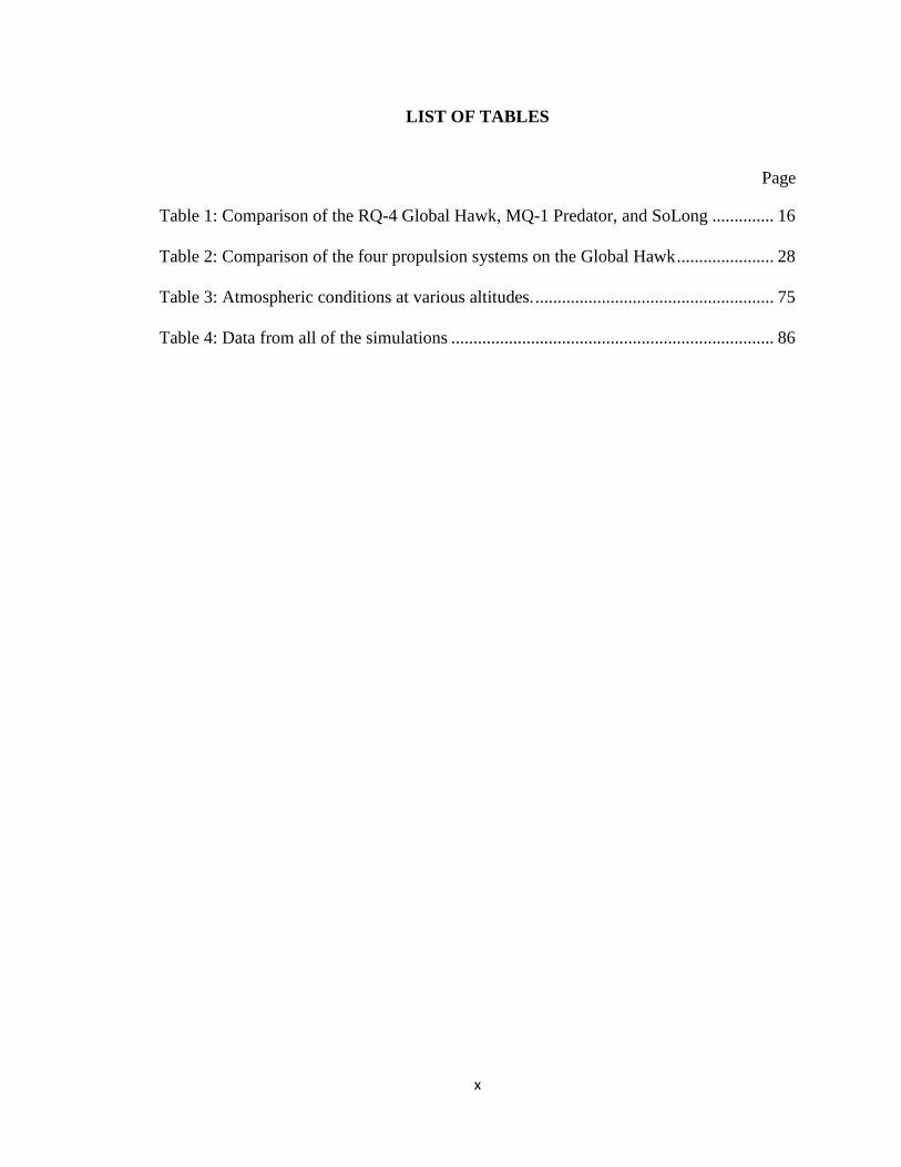
Table 1: Comparison of the RQ-4 Global Hawk, MQ-1 Predator, and SoLong .............. 16
Table 2: Comparison of the four propulsion systems on the Global Hawk ...................... 28
Table 3: Atmospheric conditions at various altitudes. ...................................................... 75
Table 4: Data from all of the simulations ......................................................................... 86

1
CHAPTER I
INTRODUCTION
As modern warfare changes through the decades, many improvements in
technology are developed. In recent years, these improvements have involved robotic
controls and alternative energy. An airplane that not only runs on nuclear power but is
also remotely controlled combines both of these improvements. This type of airplane is
discussed in thorough detail from the economics to the history to a design.
What is an Unmanned Aerial Vehicle
An Unmanned Aerial Vehicle (UAV) is an object which not only takes off,
maintains flight, and lands, but is also controlled by a remote or a programmed flight plan
as opposed to a human crew. A UAV must be able to sustain flight and be reused on
further missions. A remote-control airplane is considered a UAV while a missile
(although it may be guided by remote or satellite) is not. Most UAV‟s are small planes or
drones which can stay airborne for a given time. Many UAV‟s are used for
reconnaissance, but some fly armed combat missions for the military.

2
History of the Unmanned Aerial Vehicle
The history of UAV‟s dates back to the Civil War during the 1860‟s. The concept
was to use a balloon filled with explosives that could land on the opponent‟s ammo
depot. A similar concept was also used by the Japanese during World War 2, but neither
idea succeeded. Successful designs started during the 1960‟s with drones flying over
China and Vietnam (LIST Lab, 2003). The use of UAV‟s slowly increased until the Gulf
War when it was determined that UAV‟s were valuable for missions over rough terrain.
In recent years, commercial companies have started to develop UAV‟s for many uses
such as crop monitoring, air traffic control, and news broadcasting.
Benefits of using an Unmanned Aerial Vehicle
There are many benefits to using a UAV as opposed to an airplane with a human
crew. The most important issue is that UAV‟s can fly in dangerous environments where
human lives would be put at risk. In the military, many combat missions require visual
aid for the soldiers on the ground. However, flying a plane in a combat zone is extremely
dangerous for a human crew. In addition to military applications, a UAV can follow a
high-speed police chase or fly into the eye of a hurricane where a manned airplane could
not fly for an extended period of time. Figure 1 shows a UAV taking pictures and video
of a tropical storm over the Pacific Ocean. Typically, UAV‟s have a lower cost than a
manned airplane because one does not need to design for humans. UAV‟s can be
deployed very quickly compared to a manned airplane. UAV‟s can take high resolution
images as well as real-time video of a situation.

3
Figure 1: Picture of Tropical Storm Frank from a Global Hawk taking data for NASA in 2010
(Black and Gutro, 2010).
Drawbacks to Unmanned Aerial Vehicles
There are some major drawbacks to using a UAV. Many UAV‟s could be
confused with manned airplanes and interfere with FAA guidelines or highways. It is
nearly impossible to replace the mind and instincts of a pilot with a robot controller.
Although some UAV‟s are controlled by humans on the ground, it is difficult to fix a
problem from the ground that a human crew can do while the aircraft is airborne. It is
also hard to communicate between an autonomous UAV, the ground, and the FAA at the
same time. Also, communications can fail between the UAV and the ground crew which
can cause the airplane to crash. Another concern is liability because it is difficult to find
the owner if a UAV crashes into the ground and causes damage.

4
Using Nuclear Energy
Many universities, industries, and government agencies are trying to use energy
from nuclear sources for heat and electricity. The main idea behind using nuclear energy
is to capture the heat generated from a nuclear reaction and use it in a useful form.
Nuclear reactions can generate much more energy than conventional fuels. For example,
one kilogram of a nuclear fuel used in a reactor can generate over one billion times more
energy than the combustion of one kilogram of gasoline. The nuclear reaction can be
sustained using moderators and control rods so that the device does not reach a
supercritical state. Once the energy is generated, the heat can be used to generate
electricity, increase the temperature of a system, or implemented in other useful ways.
Using nuclear energy requires many precautions and constant observation. Some of the
fuels require complex processes to make into a form which can be used in a reactor.
5
CHAPTER II
SURVEY OF THE LITERATURE
Chapter II describes four different types of propulsion systems that can be used on
UAV‟s: Gas Turbine, Internal Combustion, Solar Electric, and Nuclear Thermal. This
chapter also details some design parameters of a UAV which differ from a piloted
aircraft.
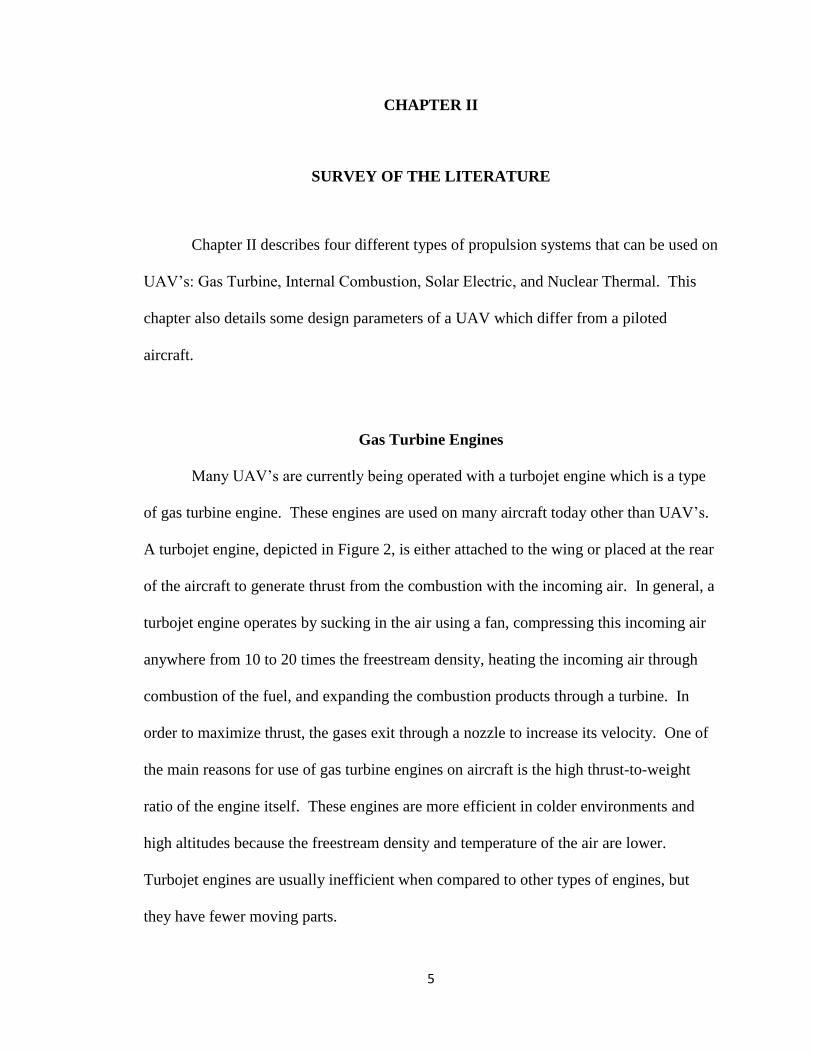
Gas Turbine Engines
Many UAV‟s are currently being operated with a turbojet engine which is a type
of gas turbine engine. These engines are used on many aircraft today other than UAV‟s.
A turbojet engine, depicted in Figure 2, is either attached to the wing or placed at the rear
of the aircraft to generate thrust from the combustion with the incoming air. In general, a
turbojet engine operates by sucking in the air using a fan, compressing this incoming air
anywhere from 10 to 20 times the freestream density, heating the incoming air through
combustion of the fuel, and expanding the combustion products through a turbine. In
order to maximize thrust, the gases exit through a nozzle to increase its velocity. One of
the main reasons for use of gas turbine engines on aircraft is the high thrust-to-weight
ratio of the engine itself. These engines are more efficient in colder environments and
high altitudes because the freestream density and temperature of the air are lower.
Turbojet engines are usually inefficient when compared to other types of engines, but
they have fewer moving parts.

6
Because propulsion systems for UAV‟s aim for efficiency over performance,
many UAV‟s use a turbofan engine as opposed to a turbojet engine. The main difference
is that most of the air in a turbofan engine does not pass through the main compressor,
combustion chamber, and turbine. This air which surrounds the turbojet portion at the
center goes through a light compression and a light expansion without passing through
the combustion chamber. Because there is no combustion through the turbofan portion of
the engine, the overall efficiency is higher because less fuel is used to propel the aircraft
(although the performance suffers slightly).
Figure 2: Picture of a typical turbofan engine. The turbofan portion of the engine surrounds the
turbojet portion. The duct fan, compressor blades, and turbine blades are all attached to the
central shaft (Cislunar Aerospace, Inc, 1998).
Theoretically, gas turbine engines operate under the Brayton cycle where the
compression and expansion of the air is isentropic and the combustion is isobaric.
However, there are some losses between the compression and the expansion. The

7
compression occurs through a series of blades attached to the central shaft. The cross-
sectional area also decreases beyond each row of blades or stators (stationary rows of
blades) in order to increase the density of the incoming air. As the air passes through
each row of blades, there are frictional losses that occur between the air and the blades
themselves. The turbine works similarly to the compressor except the air is expanded as
opposed to compressed. In the combustion chamber, the fuel (a hydrocarbon) reacts with
the oxygen in the air to produce heat which results in an increase in both temperature and
velocity. The pressure does change slightly because the process is inefficient. Jet fuel
has a typical heating value of 42.8 MJ/kg, or 127,000 BTU/gallon (Ibsen, 2001).
Because the combustion process is not 100 percent efficient, not all of this fuel is
converted into heat.
Figure 3: Brayton cycle diagram on an enthalpy-entropy diagram. The “p” states show the actual
Brayton cycle as opposed to the theoretical (Lis, 2006).
Another engine considered for a UAV is a ramjet. This ramjet may be thought of
as a turbojet without a compressor or turbine. A ramjet ignites the fuel in the combustion

8
chamber to add heat to the air and increase the velocity. Because the compressor and
turbine become less effective as the aircraft reaches supersonic speeds, the ramjet can be
more than twice as efficient at high mach numbers (Oates, 1997). One of the problems
with a ramjet is that it is difficult to start at low speeds especially at take-off. Because the
ramjet is simply a heater, there is no air flow through the engine while the aircraft is
sitting on the ground. However, if a UAV with a ramjet could be attached to another
aircraft or have a Rocket-Assisted Takeoff to bring it a high speed, the thrust would be
high enough to maintain flight.
Internal Combustion Engine
Some UAV‟s use internal combustion engines to drive a propeller and produce
thrust. A four-stroke internal combustion engine works through a series of pistons to
drive a crankshaft connected to the propeller. Depending on the type of engine, there
could be any number of pistons to drive the crankshaft. In each cylinder as depicted by
Figure 4, the piston takes in some air at the intake stroke. In a conventional gasoline
engine, the fuel and air are mixed before the intake stroke, but a diesel engine does not
mix the air and fuel. The piston compresses the air after the intake stroke. In a gasoline
engine, a spark plug ignites the fuel, but in a diesel engine, the heat from the compressed
air ignites the fuel. Once the fuel combustion is complete, the piston drives back up to
push the exhaust out of the cylinder. Internal combustion engines are not usually
implemented on large aircraft because a gas turbine engine of similar mass can produce
more thrust than its internal combustion counterpart.

9
Figure 4: Diagram of a piston in an internal combustion engine (Britannica, 2007).
Solar Electric Propulsion
Although solar electric propulsion is mainly used on spacecraft, some UAV‟s
have recently employed this technology in the propulsion system. Solar electric
propulsion works by absorbing solar energy through solar panels and generating
electricity to run a motor attached to the UAV. The motor runs off solar power during
the day and battery power at night. Barring any calamities such as sudden changes in
wind speed or accidents, a plane could fly indefinitely off of this type of power (Dighera,
2005). There are two main reasons why solar energy is used by spacecraft and not
aircraft. First, the solar energy available in Earth orbit is 1370 W/m2 while the available
energy on the surface of the Earth is only 164 W/m2based on the ionosphere, clouds, and
other impedances (Basics in Solar Energy, 2009). This also does not include the low
efficiencies of the solar panels themselves which are less than thirty percent. Second,
spacecraft in Earth orbit do not have to overcome the similar force of gravity that an
airplane does. However, an airplane does not have to carry extra fuel to perform orbital

10
maneuvers or attitude control like a spacecraft would. A UAV employing a solar electric
propulsion system must carry solar panels, electrodes, and a battery as opposed to fuel.
Only a few UAV‟s, such as the one shown in Figure 5, have used this solar electric
propulsion system, and the solar panels themselves span the entire wing. Not only is this
system inefficient, the thrust of this system is minimal compared to a turbojet engine.
Figure 5: An example of a UAV powered by solar energy. The solar energy drives motors which
are connected to propellers in order to generate thrust (La Franchi, 2007).
Nuclear Radioisotope Thermoelectric Generators (RTG)
Radioisotope Thermoelectric Generators (RTG) are used to generate electricity
from nuclear reactions. The reaction generates heat which can be used in many ways.
For most applications, an RTG is used to generate electricity from this heat source
through the Seebeck effect. This type of RTG is typically used on spacecraft (mostly in
deep space) which must carry its own power source. RTG‟s have been used in space
power systems since 1961 with SNAP-3B on a satellite. The core of the RTG is usually a
General Purpose Heat Source (GPHS) shown in Figure 6 which is used only as the heat

11
source to generate electricity. In designing a UAV, the heat generated from a series of
GPHS‟s could replace the combustion of jet fuel. One benefit of using a GPHS is the
decrease in weight required from carrying the jet fuel itself. One drawback is the cost of
the radioactive isotope. There are a few design criteria for choosing a GPHS on any
scale: the power density and half life of the radioactive isotope, the availability of fuel
and cost, radiation, and accident prevention (Angelo and Buden, 1985). The GPHS used
on the Cassini spacecraft is shown in Figure 6 and is still producing power even though
Cassini was launched in 1997. In a nuclear UAV application, one reactor could take the
place of a series of GPHS‟s for a heat source to replace the jet fuel.
Figure 6: Diagram of a General Purpose Heat Source (GPHS) RTG. A GPHS uses the heat for a
temperature increase only as opposed to electricity generation. This particular RTG is the design
used for the Cassini spacecraft (Averro, 2007).

12
Design of a UAV
There are many different criteria to consider when designing a UAV. Before the
design is completed, one must determine the purpose of the UAV. For example, if the
UAV is designed for attack missions for the military, performance is the driving factor.
For this particular study, the most important criterion is time of flight because endurance
is the main factor. The propulsion system almost always determines how long a UAV
can remain airborne. Another consideration is the material used on the aircraft. Because
endurance is important in this study, light materials which sacrifice mechanical properties
for weight are normally considered for longer flights. The weight of the fuel is also
important because it determines the payload capacity and thrust capabilities. The
geometry of the UAV (i.e. the wingspan, length, and wing dimensions) affects the lift and
drag of the aircraft itself. Lastly, cost is always a driving factor in designing a UAV.

13
CHAPTER III
STATE-OF-THE-ART TECHNOLOGY
This chapter discusses the best available technology for all of the propulsion
systems from the previous chapter. These types of designs include UAV‟s for the United
States Military and a 30 lb remote-control airplane.
State-of-the-Art Gas Turbine
Many of the state-of-the-art technologies for UAV‟s implementing a gas turbine
engine are designed for the military. The most advanced UAV using a gas turbine engine
is the RQ-4 Global Hawk which is shown in Figure 7. The Global Hawk is used on
surveillance missions for the military in order to give aid to ground troops. The Global
Hawk has an array of sensors which can detect different situations or movement on the
ground. This UAV provides surveillance for ground troops in various weather situations
or night time activity. The propulsion system on this UAV is a Rolls-Royce AE 3007H
turbofan engine which can produce 7600 pounds of thrust. The longest flight time for a
Global Hawk is over 100 hours. There are three members of the ground crew: two pilots
(one for take-off and one for everything else) and a sensor operator (USAF, 2009). The
Global Hawk uses optical and infrared cameras to survey the ground from over 60,000
feet.

14
Figure 7: Picture of the RQ-4 Global Hawk (USAF, 2009).
State-of-the-Art Internal Combustion Engine
The best technology available for a UAV using an internal combustion
engine is the MQ-1 Predator used by the US military. Unlike its Global Hawk counter-
part, the Predator may be used for combat. This particular model is equipped with two
laser-guided missiles. Because the Predator is used for armed reconnaissance, it does not
have the same ceiling that the Global Hawk does. Shown in Figure 8, the Predator is
much lighter than the Global Hawk even though it carries a series of weapons. The
Predator is a small aircraft which can also take real-time video for surveillance. The
Predator has three members for its ground crew: a pilot, a sensor operator, and a mission
intelligence coordinator (USAF, 2009). The Predator has smaller range than
reconnaissance UAV‟s and may be refueled and reloaded after using its missiles. The
engine on the Predator is a Rotax 914F four cylinder engine which generates 115
horsepower.

15
State-of-the-Art Solar Electric
Because solar electric propulsion systems are still under development, there are
very few successful attempts to fly these types of UAV‟s. However, one design claims to
have kept the UAV flying for over 48 hours. This particular aircraft, SoLong, could have
kept flying if the pilot on the ground did not get tired. SoLong flew over the Colorado
Desert for 48 hours and 16 minutes, flying on solar power during the day and battery
power at night (Dighera, 2005). Multiple controllers are needed to fly the Global Hawk
and the Predator because of the instruments or weapons on each UAV. However,
because there were no instruments on SoLong, only the pilot was needed to fly the
aircraft. The batteries were Lithium Ion cells which could be charged with over 1200
Watt-hours of energy. This battery system was almost half the weight of the entire
aircraft, but it was necessary for continuous flight. This particular UAV was built with
efficiency as the most important figure of merit. The electric power drives a motor which
turns the variable-pitch propeller.
Figure 8: Picture of an MQ-1 Predator (USAF, 2009)

16
Table 1: Comparison of the RQ-4 Global Hawk, MQ-1 Predator, and SoLong (USAF, 2009 and
Dighera, 2005).
Name RQ-4 Global Hawk MQ-1 Predator SoLong
Type of Propulsion Gas Turbine Internal Combustion
Engine
Solar Electric
Primary Function Visual Aid Armed
Reconnaissance and
Target Acquisition
Research
Contractor Northrop Grumman,
Raytheon, L3
Comm
General Atomics
Aeronautical Systems,
Inc
None
ThrustCapability 7600 lbf 115 horsepower
available
800 Watts
available
Wingspan (feet) 116 27 15.6
Length (feet) 44 6.9
Weight (lbm) 11,350 1,130 27.8
Fuel Capacity (lbm) 15,400 665 None Required
Payload (lbm) 2,000 450 None
Maximum Speed
(mph)
391 135 50
Range (miles) 10,930 454 5
Ceiling (feet) 60,000 25,000 50,000
Crew (remote) 3 3 1
Weapons None Two laser-guided
AGM-114 Hellfire
missiles
None
Cost (million $) 37.6 20
State-of-the-Art Nuclear GPHS
Because there aren‟t any UAV‟s currently using nuclear GPHS technology, this
section describes the current state-of-the-art GPHS which could be used in a UAV. In
one design, an RTG could be used to replace a motor as long as the generated power is
the same. In the case of the Solar Electric propulsion system, specifically the SoLong
UAV, a GPHS could be used to generate the same amount of power as the solar panels
without the worry of cloud cover or night. On a larger scale, multiple GPHS‟s can be put

17
together such that more power can be created from a combination of isotopes. In other
designs, the nuclear fuel could be used as a heat source instead of the combustion of fuel.
A GPHS can be placed inside the combustion chamber to generate a large amount of
heat. Depending on the design criteria, different isotopes can be used as the heat source.
For example, if performance is the most important figure of merit, an isotope with a high
specific power (like Thorium-228 with a specific power of 161 ) should be used.
However, if endurance is more important than performance, than an isotope with a long
half-life (like Cs-137 with a half-life of 30 years) could be used. With all nuclear
isotopes, cost and availability should be two of the most important figures of merit.
18
CHAPTER IV
SYSTEM COMPARISONS
In order to compare each of the propulsion systems, one specific UAV design is
used with all of the different systems. For this study, the Global Hawk is the system used
to compare the propulsion systems. Because the Global Hawk currently implements a
gas turbine engine, models of the other propulsion systems must be designed for similar
conditions. The gas turbine engine from the Global Hawk is compared to a nuclear
turbine engine using a reactor with Uranium-235 as the fuel. Uranium-235 is used
because of its energy per unit mass and its availability. Based on the mass and maximum
speed of the Global Hawk, either a solar electric or internal combustion system must be
able to produce 1600kW of power in order to match the thrust produced from the gas
turbine engine. All of the state-of-the-art systems are considered as options to replace the
current gas turbine engine on the Global Hawk. Throughout this chapter, the other three
designs (outside of the current engine on the Global Hawk) are based mostly on theory
and not on proven results.
The nuclear turbine engine can use a reactor with enriched Uranium-235 as the
isotope. The reactor would attach inside the engine so that the passing air can heat
through convection as opposed to combustion. The nuclear turbine engine would be
almost identical in size and weight to the turbofan engine that the Global Hawk currently
implements. Because the half life of Uranium is much longer than the one-year flight
time, there must be enough fuel to sustain the reaction for the entire flight.

19
The solar electric propulsion system can use Gallium-Arsenide solar cells to
absorb the solar energy especially at high altitudes. Gallium-Arsenide cells are the state-
of-the-art solar panels available today and have efficiencies as high as 29 percent (SNL,
2002). Although the solar energy that reaches the ground is approximately 170 W/m2,
the solar panels are irradiated with more energy as the altitude increases (especially at the
Global Hawk‟s ceiling of 60,000 feet). Lithium-ion batteries can be used to absorb the
extra energy from the solar panels and power the UAV during the night. Therefore,
based on the amount of power required for sustainable flight, the efficiency of the
batteries and solar panels, and the solar energy available, the required surface area of
solar cells needed is approximately 100 m2 at sea level. This area would almost cover the
entire top surface of the Global Hawk, eliminating some room for extra sensors or
scanners.
The internal combustion engine required for sustainable flight needs a power of
1600kW. Although a gasoline engine is lighter, a diesel engine is more reliable and
requires less maintenance. This diesel engine (possibly a 2-stroke) turns the propellers
and powers the rest of the subsystems. The United States Military currently uses JP-8 on
most of their engines (whether gas turbine or internal combustion), so the amount of fuel
needed for the internal combustion depends on the overall efficiency as opposed to a
difference in heating values.
The four propulsion systems considered on the Global Hawk are the gas turbine
(currently being implemented), nuclear turbine, internal combustion, and solar electric.

20
Trade-off Analysis
There many ways to compare the different propulsion systems considered for the
Global Hawk. There are eight categories described in this section of Trade-Off Analysis:
Size & Weight, Efficiency, Safety, Reliability, Lifetime, Fuels, Cost & Availability, and
Public Acceptance. Table 2 at the end of the section compares all four propulsion
systems with a figure of merit indicating which system excels in a particular category.
Size and Weight
For the propulsion system itself (not including the fuel), the gas turbine and the
nuclear turbine systems have an advantage over the solar electric and the internal
combustion. The current gas turbine engine on the Global Hawk weighs approximately
1600 pounds. The nuclear turbine engine would weigh the same amount as the gas
turbine engine because there are no significant changes in the engine itself besides the
fuel. The solar electric has an advantage over the internal combustion because solar
panels weigh much less in comparison to an internal combustion engine. An electric
motor required for the solar electric also weighs less than an internal combustion engine.
Because there are propellers required for the internal combustion and solar electric
systems, the two turbine engines weighs less than the combined total of the motor and the
propellers for the solar electric but not the internal combustion.
For the fuel, the nuclear turbine has a slight advantage over the solar electric, but
both have a significant advantage over the internal combustion and gas turbine. Neither
the nuclear turbine nor the solar electric systems require a fuel tank which can take up a
significant portion on the weight of the Global Hawk. The mass of the reactor and the
fuel required to sustain the nuclear reaction for one year is negligible when compared

21
with the mass of the Global Hawk. Lithium ion batteries have a gravity density of over
200 . Therefore, assuming that the propellers operate at the highest efficiency
throughout the night and taking into account the gravity density, the required weight of
batteries can exceed 8000 pounds. These batteries must also be placed throughout the
Global Hawk which takes up a large amount of space. Although this weight may seem
high, it is still smaller than the amount of jet fuel that the Global Hawk uses for a 100
hour flight.
It is nearly impossible to carry enough fuel for the gas turbine or internal
combustion to sustain flight for over a year. Assuming that the maximum fuel capacity is
the amount of fuel used by the Global Hawk‟s current gas turbine engine for a 100 hour
flight, it would take over 3.7 million pounds of jet fuel. This does not consider the
increase in size of the fuel tank or the overall weight of the Global Hawk. To put this
into perspective, the external tank for the space shuttle contains about 1.6 million pounds
of fuel. Therefore, using jet fuel requires the Global Hawk to land, refuel, and take-off or
aerial refueling.
Overall, the nuclear engine has a clear advantage in size and weight, followed by
solar electric, then gas turbine and internal combustion.
Efficiency
In terms of overall efficiency of the systems considered, internal combustion and
gas turbine engines have the highest efficiencies, followed by solar electric and nuclear
turbine. Gas turbine and internal combustion engines have similar efficiencies, but the
internal combustion has the higher efficiency. The internal combustion engines,
especially diesel engines, have efficiencies close to forty percent. Gas turbine engines,

22
even with high bypass ratios, have efficiencies slightly higher than thirty percent. Solar
electric systems have the next lowest efficiency. Based solely on the efficiency and not
the available power, the solar cells have less than 30 percent efficiency which does not
include the inefficiencies of the batteries. The nuclear turbine engine has the lowest
efficiency. Its efficiency would be defined as the ratio of heat transferred to the air and
total heat generated from the nuclear reaction. When factoring in the maximum
temperature of the reactor, the velocity of the air, and temperature of the air, the
percentage of heat transferred to the air is low. Losses would occur through heat transfer
to other parts of the engine and the cooling of the nuclear reactor.
Safety
The safety of each propulsion system is compared using the worst possible
accident. None of the systems are considered safe, but the safest would be the internal
combustion engine followed closely by the gas turbine. Failures can happen inside the
internal combustion engine; however, the engine itself does not explode or harm
components on the Global Hawk. The UAV can coast down to the nearest landing
surface especially from 60,000 feet in the air. Because the gas turbine engine is located
outside the fuselage at the aft of the aircraft, an accidental explosion inside the gas
turbine has a small chance of harming the components of the aircraft. An engine fire or
failure of the components can cause the engine to shut down. When this happens, the
controller can land the UAV in a similar fashion as an accident with the internal
combustion engine. However, an explosion to the UAV for either one of these engines is
still safer than the solar electric or the nuclear turbine engine. The solar electric is
slightly safer than the nuclear turbine engine. If there is a failure in a solar electric
23
system and the UAV crashes on the ground, battery fluid can leak from inside the
aircraft. Because Lithium is one of the most reactive elements, a leak in battery fluid
from 8000 pounds of batteries can cause some serious damage.
The most dangerous system is the nuclear turbine. The nuclear turbine engine
itself is not dangerous, but collecting the nuclear energy is extremely dangerous. Not
only is air traveling at 400 mph hitting the nuclear reactor attached to the inside of the
combustion chamber, but controlling the amount of heat generated by the nuclear fuel is
difficult. If the coolant inside the reactor fails or leaks, the engine could melt. The fuel
itself would be safe because it can be encased in stainless steel containers or fuel rods.
Another safety issue is the nuclear material ending up in the wrong place if the UAV
crashes to the ground and a terrorist gets control of the reactor. However, because the
nuclear fuel is not weapons grade, more procedures would be needed to make a bomb.
The gas turbine is the safest propulsion system examined, followed by the internal
combustion, then solar electric and nuclear turbine.
Reliability
Reliability is a combination of how long a particular propulsion system has been
in commercial use, how much research has been conducted, and the number of failures
per use. The internal combustion engine is the most reliable of the four propulsion
systems. Diesel engines are some of the most reliable engines especially because they
have been used since Rudolf Diesel was granted the patent in 1898. Gas turbine engines
follow the internal combustion engines in reliability. Many of the failures in aircraft do
not involve the engine itself. One of the most common failures with gas turbine engines
(and also nuclear turbine) involves birds that get sucked through the engine. When a bird

24
flies into the engine, the compressor blades may fail which may causes an engine fire.
Internal combustion engines and gas turbine systems need maintenance which could keep
them from being airborne for a year. Solar electric propulsion systems are more reliable
than the nuclear turbine because there are no nuclear turbine engines in existence today.
There are a few examples of solar electric UAV‟s (like SoLong) that have flown
successfully. One problem with solar electric UAV‟s is the amount of electrical
connections throughout the aircraft. With the amount of electrical connections in a
Global Hawk powered by a solar electric propulsion system, the probability that one of
these connections fails over the course of one year is high. Because there are no nuclear
turbines being used on UAV‟s, they have the lowest reliability.
Lifetime
The Lifetime compares how long each system would last before its components
begin to fail (assuming no accidents and unlimited fuel). Theoretically, a nuclear turbine
engine has the longest lifetime because of the fewest number of supporting components
to the fuel. Assuming the compressor and turbine blades do not fail, the engine could last
as long as the reactor continues to produce heat. The Voyager spacecraft is still
producing data 33 years after launch using an RTG as its power source. Although this
RTG does not have any moving parts like a turbine, it shows that nuclear reactions can
last for a long time without maintenance. The solar electric propulsion system has the
next highest lifetime. Although the solar cells can last for over 20 years, the batteries fail
from the constant recharging and discharging. The batteries could last long enough to
keep the Global Hawk airborne for over a year, but they will not last much longer than
the year. Internal combustion engines have the next longest lifetime followed by gas

25
turbine engines. These engines follow the nuclear turbine and solar electric systems
because there are many parts such as fuel lines that fail before one year of continuous
ignition.
Fuels
The fuel for each of the propulsion systems is unique and only works with its own
particular system. The nuclear reaction in this particular reactor involves Uranium-235
and neutrons. To start the reaction, the Uranium-235 absorbs the neutron and releases
fission fragments, gamma radiation, heat, and more neutrons. These neutrons are then
absorbed by other Uranium-235 particles which undergo the exact same process. Once
the chain reaction begins, the control rods absorb excess neutrons to keep the reaction
from going supercritical. To keep the Global Hawk airborne for the one year time frame,
there needs to be enough Uranium-235 to maintain the reaction for one year.
Jet fuel and diesel fuel are hydrocarbons which burn in air. This combustion
converts the fuel and oxygen from the air into carbon dioxide and water vapor. The
difference between the two fuels is the chemical composition which changes the
combustion temperature and other physical properties. Because both gas turbine and
internal combustion engines would both run on the same fuel, this figure of merit is the
same for both. However, neither comes close to the amount of energy per unit mass of a
nuclear isotope. Uranium-235 in a reactor can produce over 10,000 times more energy
per unit mass than jet fuel or diesel fuel (Patzek, 2003). Finally, the solar electric
propulsion system does not require any fuel because it uses the energy from the sun to
drive the motor and the propellers. Therefore, solar electric gets the highest rank for this
figure of merit.

26
Cost & Availability
In terms of both cost and availability, the internal combustion engine is the clear
winner. Diesel engines are readily available in many automobiles today and for many
aircraft. In addition, many buildings have diesel generators as a back-up power source.
Jet engines are also readily available from companies such as General Electric and Pratt
& Whitney. The best estimate for the cost of the Rolls Royce turbofan engine on the
Global Hawk exceeds one million dollars. Because the cost of a high-quality, light-
weight diesel engine does not exceed one million dollars, the internal combustion has a
lower cost than the turbofan engine counterpart.
Solar electric follows the gas turbine engine based on the cost of the solar panels
and the batteries. Gallium Arsenide solar panels are difficult to purchase especially in
bulk because they are still under development. However, one estimate shows that one
square meter of Gallium Arsenide costs 10,000 dollars (SNL, 2002). Based on the need
for solar panels, the total cost for the cells alone is one million dollars. An optimistic cost
per kWh for Lithium ion batteries is 250 dollars per kWhr (Peterson, 2009). Based on the
energy required to power the UAV at night, the cost of the batteries alone (not including
the electrical connections or the engineering necessary to connect the batteries and the
solar panels) is approximately two hundred thousand dollars.
Although the availability of Uranium-235 is reasonable, the nuclear turbine
propulsion system has the highest cost. There are millions of pounds of Uranium
available for purchase. The market value for uranium back in 2003 was $10.75 per
pound, and in early 2007 the price rose to $100 per pound (ANL, 2011). After including
the cost of the same turbofan engine as the current Global Hawk (without the fuel lines or

27
spark plugs) and adding in the cost of the reactor, the nuclear turbine engine is clearly the
most expensive engine. The nuclear turbine engine is also the least available because it
has never been developed.
Public Acceptance
Of the four designs under consideration, the solar electric propulsion system
would have the best public acceptance because there is no fuel required. Because green
processes are generally more accepted by the public, the solar electric propulsion system
would have a higher public acceptance then either of the combustion engines. There are
no emissions from the solar electric propulsion system as opposed to the gas turbine or
internal combustion engines. Both the internal combustion and gas turbine engines are
generally accepted by the public because they have been used commercially for a long
time. However, the diesel engine gets the edge over gas turbine because renewable
energy (biodiesel) can be used in a diesel engine. Although biodiesel would not be used
with either engine because of the US military‟s requirement to use JP-8 fuel, the public
acceptance would still be higher for the diesel engine.
The nuclear turbine engine has the worst public acceptance because of the nuclear
energy. Generally, the public does not accept the use of nuclear energy in any form even
though it has the highest specific power of any resource or method for energy production.
The radiation from nuclear energy is not as harmful as the public generally accepts. The
public looks at accidents such as Chernobyl or Three Mile Island as reasons why nuclear
energy should not be used. The public may not be aware that 20 percent of the energy
production for the United States comes from nuclear power (World Nuclear Association,
2011).

28
Table 2: Comparison of the four propulsion systems on the Global Hawk. A 4 indicates the best
of the systems for that particular category, followed by 3, 2, and 1. Both the gas turbine and
internal combustion engines require refueling before the one year time frame is completed.
Type Nuclear
Turbine
Gas Turbine Internal
Combustion
Solar Electric
Size & Weight 4 2 1 3
Efficiency 1 3 4 2
Safety 1 3 4 2
Reliability 1 3 4 2
Lifetime 4 1 2 3
Fuels 3 1.5 1.5 4
Cost &
Availability
1 3 4 2
Public
Acceptance
1 2 3 4
Choice of Engine
After careful review of all four types of engines, the choice for the design in this
particular scenario is the nuclear turbine engine. Because the gas turbine and internal
combustion engines both require refueling before the one year time frame, they are not
the best options in the future. The main disparity between the nuclear turbine and solar
electric options is practicality. In order to produce the amount of power required to keep
the Global Hawk airborne, the entire body of the aircraft must be covered with solar
panels. In addition, the mass and volume of the batteries required would not fit into the
current design. Some of the payload would have to be removed in order to support the
space that the batteries require. Therefore, the nuclear turbine engine is the best option
going forward with a new superior design.
29
CHAPTER V
HISTORY OF THE NUCLEAR AIRPLANE
Since the use of the atomic bombs which ended World War 2, countries
throughout the world have been researching the use of nuclear energy for many
applications. Many scientists and engineers have been excited about the potential of
nuclear energy whether in a power plant or the field of medicine. During the 1940‟s,
many thought that nuclear power could replace all other means of creating energy.
Power production from nuclear energy has been used across the world and has replaced
more conventional methods of energy production. In some countries, nuclear power is
responsible for over 75 percent of power production. One particular area of research
which has never achieved an operational level is propulsion from nuclear energy. Since
the atomic bomb was dropped, there have been multiple attempts by many countries to
fly an airplane on nuclear power; however, no one has successfully flown an airplane on
nuclear fuels. Beginning in 1946, many US government agencies began conducting
studies about the cost and time frame of building an airplane operating on nuclear fuels.
Funding for the nuclear propulsion of aircraft lasted until 1961, and funding for missiles
ended in 1964. Since that date, no one has invested significant funding in these types of
projects.
30
Beginning of the Research
Although the purpose of the Manhattan Project was to create an atomic bomb, the
first research on a nuclear airplane began prior to the atomic bombs. In 1942, Enrico
Fermi brought the idea to propel an aircraft using the same nuclear energy from the bomb
(Colon, 2007). At first glance, the biggest obstacle of the design was how the radiation
would affect the crew flying the aircraft. Prior to 1946, most of the research involved
discussions on possible designs and uses of a nuclear airplane. The general consensus
was that using nuclear power to propel a bomber could complete unlimited missions to
Russia or other countries without landing. Funding for the nuclear airplane project
officially began on May 26, 1946 when the Air Force gave a contract to Fairchild Engine
and Airplane Corporation (Stoffel, 2000). The project was awarded 1.3 million dollars in
FY 1946 (York, 1970). In addition, the Nuclear Energy for Propulsion of Aircraft
(NEPA) agency was born after the contract was awarded to Fairchild. The two major
goals of NEPA were determining the feasibility of creating an airplane running on
nuclear fuel and educating the aircraft industry about the uses of nuclear energy in
propulsion (Stoffel, 2000). This included moderator materials, nuclear fuel, and radiation
shielding.
The funding required for building a nuclear airplane was enormous even back in
the 1940‟s. Fermi built the world‟s first nuclear reactor (shown in Figure 9) at the
University of Chicago in December 1942. After Fermi pulled the control rods out, the U-
235 in the reactor attained criticality. Until 1949, the Air Force was the only acting
government agency working with NEPA. Fairchild Corporation was also the only private
contractor working on the project until 1948. At this time, a group of MIT scientists and

31
engineers, known as the “Lexington Project,” conducted a study on the feasibility, cost,
and time table for constructing a nuclear airplane (Stoffel, 2000). The conclusion of the
Lexington Project was that a nuclear flight was a strong possibility with the timetable of
15 years and funding in excess of 1 billion dollars. In terms of science, the largest hurdle
to overcome was not the intense radiation coming from the nuclear fuel but the
propulsion system itself, whether it was a ramjet or a rocket engine.
Figure 9: Some of the materials used by Enrico Fermi to build the first nuclear reactor
(ThinkQuest, 1999).
Regardless, the Atomic Energy Commission (AEC), NACA (the predecessor to
NASA which was formed in 1958), and the Navy joined in the effort with the Air Force
to build a nuclear airplane. Government facilities were organized primarily at Oak Ridge
National Laboratory and Lawrence Livermore National Laboratory. At Oak Ridge
National Laboratory, a large portion of the work was supporting other projects and
organizations throughout the remainder of the nuclear aircraft research (Jordan et al,
1957). Finally, in 1951, NEPA had completed its primary goals of determining whether a

32
nuclear airplane could be built and therefore was renamed to Aircraft Nuclear Propulsion
Program (ANP).
General Electric’s First Attempt
Initially, the Air Force wanted a flight test of and experience using a nuclear
engine regardless of application or performance characteristics. The first contract for a
nuclear engine, as part of the ANP, was awarded to General Electric in March 1951.
General Electric was also awarded a contract from the AEC to develop a nuclear reactor
for other purposes besides aircraft propulsion. General Electric‟s proposed architecture,
named P-1, was a direct-cycle nuclear turbojet engine designed for a supersonic jet. The
P-1 project used an R-1 reactor (shown in Figure 10) to heat the air in the combustion
chamber. This particular design uses the heat from nuclear fuel to power four separate
turbojet engines. General Electric‟s first timeline suggested a ground test of the engine in
1954 and a flight test in 1957 (Stoffel, 2000). However, in March 1953 a committee
composed of members from the Air Force Scientific Advisory Board suggested rolling
back on some of the funding for the nuclear airplane. The P-1 project got cancelled in
May 1953 because the Air Force decided that there were no military applications for this
particular research. At the time of cancellation, the engine and the reactor were both in
the final development stages.

33
Figure 10: Diagram of the R-1 nuclear reactor used in the P-1 engine design by General Electric
(Stoffel, 2000).
General Electric’s Research Role
After the cancellation of the P-1 engine, General Electric took a research role
towards fabricating a nuclear airplane. Instead of using the nuclear power plant for
aircraft propulsion, General Electric began a series of Heat Transfer Reactor Experiments
(HTRE) to assist the construction of a nuclear airplane. The majority of the research and
development of General Electric‟s assistance to ANP occurred in Cincinnati, Ohio, while
most of the testing was completed at Idaho National Laboratory. Throughout the
remainder of the ANP program, General Electric tried to work on the direct cycle nuclear
turbojet engine through these HTRE experiments. In 1951, Pratt & Whitney was
awarded a contract to study an indirect-cycle nuclear engine where the heat from the
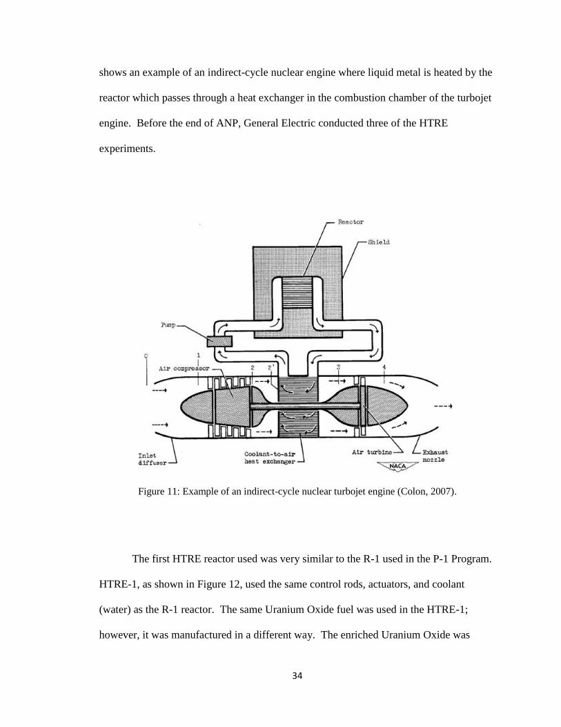
nuclear reactor is added to the air through a heat exchanger (Matej, 2005). Figure 11
34
shows an example of an indirect-cycle nuclear engine where liquid metal is heated by the
reactor which passes through a heat exchanger in the combustion chamber of the turbojet
engine. Before the end of ANP, General Electric conducted three of the HTRE
experiments.
Figure 11: Example of an indirect-cycle nuclear turbojet engine (Colon, 2007).
The first HTRE reactor used was very similar to the R-1 used in the P-1 Program.
HTRE-1, as shown in Figure 12, used the same control rods, actuators, and coolant
(water) as the R-1 reactor. The same Uranium Oxide fuel was used in the HTRE-1;
however, it was manufactured in a different way. The enriched Uranium Oxide was

35
mixed with Nickel-Chromium for higher reliability and strength. Niobium was added to
the Nickel-Chromium for improved oxidation resistance. Beryllium was used as a
neutron reflector on the outside of the fuel. The test facility, as shown in Figure 13, for
all of the HTRE testing occurred on top of a train car with turbojet engines surrounded by
radiation shielding. In terms of performance characteristics, the air inside the engine was
heated to 1350 degrees F (1010 K). Some important observation through the HTRE-1
test included the lack of contamination of the surroundings and the continuation of the
reaction after the fuel was damaged (Gantz, 1960).
Figure 12: Picture of the HTRE-1 Reactor (Stoffel, 2000).

36
Testing for the HTRE-1 was very successful and led to the development of
HTRE-2. Initially, a few of the fuel elements failed on the first test; however, the test
continued after the elements were replaced, and the reactor ran for over 140 hours (past
the 100 hours goal) with a maximum power of approximately 20 MW (Stoffel, 2000). In
short, HTRE-1 met all objectives when powering one of the X-39 engines in addition to
improving safety and maintenance operations. However, the results of this experiment
were not promising enough to consider using HTRE-1 on an operational aircraft. The
major conclusion from the HTRE-1 experiments was that flying an aircraft on nuclear
power was a very viable option. The HTRE-2 design was essentially the same as the
HTRE-1 design except for an opening through the reactor down the center. This void in
the center of the reactor was used for test articles. Some of the reactor fuel elements were
removed, and to compensate for the lost fuel, four inches of Beryllium were added to
improve the neutron reflector (Stoffel, 2000). After four tests, the results had improved
over those from the HTRE-1. The temperature of the core reached over 4400 degrees F
(2700 K), and some of the fuel elements operated for almost 1000 hours.
Figure 13: Picture of HTRE-1 at the test facility (Colon, 2007).

37
After many improvements from HTRE-1 to HTRE-2 through extensive testing,
the HTRE-2 reactor was advanced to the HTRE-3 reactor. The purpose of the HTRE-3
design was to construct a system that could be placed on an aircraft as opposed to the
other two which were used for feasibility studies. The HTRE-3 reactor was significantly
different than the previous two in terms of the moderator, overall design, and test
experiments. Instead of liquid water, the moderator was a solid Hydrided Zirconium,
which allowed the air to cool the moderator. In addition to having more fuel elements
than its predecessors, the HTRE-3 reactor was able to power two X-211 engines as
opposed to a single X-39 engine. Figure 14 shows the HTRE-3 reactor connected to two
of the X-211 engines. Most importantly, the size and shape of HTRE-3 allowed it to fit
into an aircraft to be used on a future mission. By the end of 1958, HTRE-3 operated for
over five straight days, powered two turbojet engines, and had little damage to any of the
fuel elements. The starting mechanism for HTRE-3 used only nuclear power as opposed
to prior tests which had to be started using chemical power through the turbine before
switching to nuclear power.

38
Figure 14: HTRE-3 connected to two X-211 engines without any of the support structure
(Colon, 2007).
Development of a Bomber using Nuclear Propulsion
Due to the apparent success of the early HTRE tests, the Department of Defense,
along with the approval of the AEC, decided to authorize funds for development of the
nuclear propulsion system to be used on a bomber aircraft. Convair won a contract in
1952 to perform radiation testing on a B-36 peacekeeper. In 1955, during the
development of the HTRE reactors, the AEC detailed some of the results from the
research and recommended more funding. This new project, now unclassified, continued
the original contract with a new purpose of propelling the B-36 bomber with nuclear
engines. This particular bomber would have a ceiling of almost 40,000 feet and weigh
over 400,000 pounds, but its most important aspect was that it had the space to
accommodate a nuclear engine. Coming into service in 1948, the purpose of a B-36
Peacekeeper was the evasion of fighter jets at 40,000 feet and the ability to drop atomic

39
bombs over a 10,000 mile range (Ford, 1996). The particular bomber used for the test
bed was a model, shown in Figure 15, whose fuselage and cockpit were damaged by a
tornado at Carswell Air Force Base in Fort Worth, Texas. This was significant because
the cockpit for the test bed (later named NB-36 Crusader) had to be replaced anyways
because of the radiation shielding required for the crew.
Figure 15: Picture of the B-36 Bomber and the initial proposed propulsion system (Colon, 2007).
With a clear military goal and the necessary funding, the research for the nuclear
engine could continue with a specific goal for the first time in the history of the ANP.
The original goal was a nuclear ground test in 1959 with a flight test shortly after. The
plane flew 47 separate times during the mid-1950‟s with the reactor on board (USAF,
2010). The reactor was operational during a handful of flights, but the airplane never
went to complete nuclear power. Some generals in the army were very optimistic about
the progress during the summer of 1956. However, more budget cuts shortly followed
the apparent lack of feasibility for this concept, and the project was delayed. Conflicting

40
opinions over the progress delayed significant funding: one committee wanted to see a
plane fly as soon as possible while another wanted to focus on a suitable reactor and
propulsion system (this happened prior to the development of HTRE-3). Improved
funding came back in July 1957 after more discussions between top members of the Air
Force and the Department of Defense. Fluctuating funding continued until the project‟s
cancellation in 1959.
Project PLUTO
One other project that tried to implement nuclear propulsion was Project PLUTO,
a missile incorporating a nuclear ramjet. A nuclear ramjet is a simple design where the
air enters the engine through the inlet nozzle, heated by the nuclear reactor, then
accelerated through an exit nozzle. Project PLUTO was born in January 1957 with its
main laboratory at Lawrence Livermore National Lab (LLNL) in Berkeley, California.
Project PLUTO was independent of ANP and other research related to nuclear airplanes.
The test site for its components was at a remote facility in Nevada across the desert in a
LLNL site.
The main goal of Project PLUTO was creating a missile which could be launched
from the United States and reach almost anywhere in Russia. This missile, known as the
SLAM (Supersonic Low-Altitude Missile), would implement this nuclear ramjet design.
However, the nuclear ramjet engine would not be able to reach supersonic flight by itself.
Instead, a group of chemical rockets would help launch the SLAM missile to supersonic
speed where the nuclear ramjet would take over and be able to take the missile to
anywhere in Russia at speeds greater than Mach 4. Figure 16 details the payload on this

41
particular missile which included a set of nuclear warheads in addition to the nuclear
reactor. The mission of this missile included dropping the warheads and flying over
Russia emitting radiation from the nuclear reactor.
Throughout its testing period, the testing for these engines was very successful.
The Tory-IIA and Tory-IIC ramjet engines were tested on railcars in Nevada, with the
Tory-IIC engine producing over 170 kN of thrust from over 465,000 fuel elements
(Parsch). The Tory-IIC engine was ready for flight testing at the time of cancellation.
The biggest hurdle that the Project PLUTO team could not overcome was the testing. It
was difficult to test such a missile because of the radiation coming from the reactor.
Therefore, testing over the United States was not an option. Some proposed testing over
the Pacific Ocean, but one could not test the effectiveness of the warheads dropped from
the missile. In July 1964, after over 250 million dollars of funding, the project was
cancelled. The two main reasons for cancellation were the lack of testing ability and the
development of ICBMs. ICBM‟s were cheaper and could reach inner parts of Russia
without being shot down.

42
Figure 16: A Diagram of the SLAM missile (Platform389, 2004).
Influence of the USSR
There were a couple of events during the later part of the 1950‟s which helped
influence greater funding towards the nuclear engine research. Because of the constant
conflict between United States and the USSR, many United States citizens felt the need
to beat the Russians in all aspects of life. When the USSR launched the first satellite,
Sputnik, into orbit on October 4, 1957, many people thought that they would launch a
nuclear propelled aircraft soon after. This launch also affected the mindset of those
involved in other high-technology projects such as ANP. Some thought that if the
Russians could launch a satellite into orbit then a nuclear aircraft would soon follow.
Second, there were inaccurate claims made during the late 1950‟s. Although the USSR
had a young nuclear aircraft program, some congressional sources claimed that Russia
had developed and flight-tested a nuclear airplane, which was not true. This is an

43
example of such statements coming from an article from the December 1, 1958 issue of
Aviation Week:
On page 28 of this issue we are publishing the first account of Soviet nuclear
powered bomber prototype along with engineering sketches in as much detail as
available data permits. Appearance of this nuclear powered military prototype
comes as a sickening shock to the many dedicated U. S. Air Force and Naval
aviation officers, Atomic Energy Commission technicians, and industry engineers
who have been working doggedly on our own nuclear aircraft propulsion
program despite financial starvations, scientific scoffing and top level
indifference, for once again the Soviets have beaten us needlessly to a significant
technical punch.
Page 28: A nuclear powered bomber is being flight tested in the Soviet Union.
Completed about six months ago, this aircraft has been observed both in flight
and on the ground by a wide variety of foreign observers from communist and
non-communist countries…As long as a year ago there were brief but specific
mentions in the Soviet technical press of successful ground testing of atomic
aircraft power plants. Recent speculative stories in the Soviet popular press
suggest conditioning the Russian people to an announcement of a spectacular
achievement by an atomic powered airplane in the near future, probably a non-
stop non- fueled flight around the world (York, 1970).
It turns out that this story was false, but the public saw this and began to fear. This article
was not the only source of false evidence, but it was difficult to discern the truth from so
much information feeding the public.
Cancellation of all Funding
During the early 1960‟s, the United States was focused on the space race with the
USSR. In 1961, President Kennedy cancelled funding for ANP and all nuclear airplane
projects, stating that 15 years of work and over one billion dollars were invested with no
clear results. This funding, as stated by President Kennedy in September 1962, was
44
moved towards the Nuclear Engine for Rocket Vehicle Assembly (NERVA) program.
The NERVA program was a continuation of both the ANP and the ROVER program
which started in 1956 towards developing missiles with nuclear propulsion systems. The
research, which was originally geared towards flying a nuclear airplane and development
of nuclear ICBM‟s, was now directed towards space exploration. The NERVA project
was funded by the Air Force and the AEC for several years until 1973. Between 1962
and 1973, the NERVA program spent (as shown in Figure 17) over 1.4 billion dollars
from NASA, the Air Force, and the AEC. The nuclear research continued with over 20
reactors built and tested during the NERVA program. However, like the ANP, the
NERVA program did not produce an operational propulsion system. The NERVA
program was cancelled in 1973 because of lack of results, loss of public acceptance, and
the elimination of the Apollo program.

45
Figure 17: Funding levels for the ROVER program from 1956 through 1961 and the NERVA
program which started in 1961 (Dewar, 2004).
Lessons Learned from Nuclear Engine History
Throughout the years that followed the first uses of the atomic bomb, there are
many lessons that can be learned from the failed attempts to create a nuclear engine for
aircraft. The first problem was the fluctuating funding throughout the entire ANP and
NEPA programs. Because of the change in funding levels, many programs were
cancelled and restarted. For example, the P-1 system would have been flight tested by
1957 if the funding was not cancelled. However, many of the generals and politicians
involved in making the big decisions did not approve of the progress. The important fact
was that the science was making significant strides towards nuclear flight before funding
levels changed. Most programs were moving towards the required deadline of nuclear
flight before funding was cut.
Many of the decision makers did not understand that nuclear energy was not well
understood prior to the beginning of NEPA, so a successful nuclear flight was going to

46
take lots of time and money. As early as 1947, the Air Force thought nuclear flight was
possible in five years and continued the theme “Fly Early” even if the scientists knew that
goal was not feasible (Stacy, 2011). This showed the detachment of the generals from
the science and engineering. In addition, both Pratt & Whitney and General Electric got
funding to complete two separate engines for the same goal. If the scientists of 1950
understood nuclear energy as well as those in the present day, most of the funding would
have gone towards one specific project instead of dealing it out to multiple companies.
The Lexington project predicted that a nuclear flight was probable after fifteen years and
one billion dollars back in 1946. In 1961, the project spent fifteen years and
approximately one billion dollars before all funding was cut without a successful nuclear
flight.
Another key lesson learned from the ANP program was that there was no clear
reason for sustaining a nuclear flight other than to just do it. At the beginning of NEPA,
the Air Force wanted to develop a nuclear airplane as quickly as possible after
determining its feasibility. However, with funding from the Department of Defense,
there needed to be a clear objective for sustaining nuclear flight. By the time a military
objective was determined in 1955, too much funding was used on other projects with
little in common.
Finally, the last lesson learned from the history of the nuclear airplane research is
the influence of the public. Given that most of this work was classified until the late
1950‟s, the public did not know about the research on nuclear airplanes. However, once
the public discovered the research through the politicians and news articles, many wanted
to see a nuclear airplane fly because of the psychology of beating the Russians. The

47
influence of the public allowed certain aspects of the ANP program to continue even if
they were not going to succeed. At this point in time, the public was just starting to learn
about nuclear energy, but they did not know about any side effects such as radiation.
The main point from the history of the nuclear airplane is that the science and
engineering developed during the ANP program made a nuclear flight attainable, but
there were too many hurdles and bumps along the way to make it possible.

48
CHAPTER VI
PROPOSED SYSTEM
From the trade-off analysis, the choice of propulsion system for the Global Hawk
depends on many different situations. For a private company where reliability and cost
are the driving factors, either the internal combustion or the gas turbine systems would be
the best option. If a politician is trying to support a design where public acceptance is
important, the solar electric system may be the best choice. If the military is proposing a
design where performance is more important than cost, the nuclear turbine engine would
be the optimum choice.
Chosen Design
The chosen design using nuclear fuel is a nuclear turbine engine. There are two
major changes to the current propulsion system on the RQ-4A Global Hawk. The first is
the elimination of jet fuel in the combustion chamber of the turbofan engine to be
replaced by a nuclear reactor attached to the central shaft using a set of bearings. The
bearings allow the central shaft to rotate but not the reactor itself. The second change is
the expansion of the compressor and turbine so that the bypass ratio decreases from 5 to
2.5.
Fuel
In deciding which fuel to use, there are two possible designs for the nuclear
turbine engine: reactor and General Purpose Heat Source (GPHS). The reactor design

49
would use one reactor attached to the central shaft. The General Purpose Heat Source
design uses a series of GPHS modules attached to the central shaft.
For the reactor design, the most available fuel is Uranium-235. Uranium-235 has
a specific energy of 88 MJ/kg, meaning that, theoretically, 88 MJ of heat are released for
every one kilogram of U-235 reacted. In the reactor itself, the Uranium is in the form of
UO2 in a Tungsten matrix. The ratio of tungsten to fuel is 60-40, and graphite is the
moderator. The fuel must be enriched Uranium-235 because the size and weight of the
reactor is less than that of natural-Uranium reactor. For the design, the fuel matrices are
placed in a circle around a Beryllium core which acts as a reflector for the neutrons. In
order to cool the reactor, cooling tubes are placed inside the reactor. During the NERVA
program in the 1960‟s, the reactors were cooled through the use of cooling tubes which
were adjacent to the fuel rods themselves. However, the incoming air will also cool the
reactor, so a powerful coolant system is not necessary. Power can be extracted from both
a nuclear reactor and a GPHS.
For the GPHS design, the best fuel available for use is Pu-238. Pu-238 GPHS‟s
have been used in space on Cassini and other space-probes as a power source. Unlike a
reactor, the radioactive decay from Pu-238 produces enough heat to generate electricity.
GPHS units are reliable and can produce both power and heat. These heater units can
help produce up to 900 Watts of electrical energy even at low efficiencies. Some future
space missions have planned on using over 100 of these heater units for electricity and
heat. Plutonium fuel production is one of the most important areas of research for the
Department of Energy and NASA. The United Kingdom has a large stockpile of PuO2
which could be used to make Pu-238 (Beach et al, 2009).
50
Possible Designs
There are many possible designs for using a nuclear fuel in a power or propulsion
system for a UAV. The nuclear fuel must replace the heat from the jet fuel. One clear
advantage of using a nuclear fuel is the elimination of fuel lines and tanks for the jet fuel.
This eliminates not only the valves and injectors but also decreases the overall weight of
the aircraft. Therefore, performance characteristics such as range and lift can increase
based solely on the decrease in weight of the aircraft. To use nuclear fuel, either a reactor
or a series of GPHS modules must be implemented inside the gas turbine engine. In a
smaller aircraft, a series of GPHS modules can be used because the amount of heat
required is smaller. GPHS modules have been proven to be more reliable than a reactor.
For a smaller UAV such as a Predator, a series of GPHS modules could be used
inside the combustion chamber. Currently, the Predator uses an internal combustion
engine to drive the propellers. The MQ-1 Predator carries about 700 pounds of fuel at
take-off in addition to the weight of the tank which holds the fuel (USAF, 2009). In
order to implement a nuclear propulsion system, the internal combustion engine could be
replaced with a gas turbine engine and a series of GPHS modules. One study claims that
a GPHS module can produce maximum temperatures of 2400K (El-Genk and Tournier,
2004). A GPHS module can produce heat only instead of heat and electricity (although
most are designed to produce both as part of an RTG unit). Therefore, the GPHS
modules could produce not only the heat required to produce thrust through the engine
but also assist in generating the electrical power required to operate all of the equipment
onboard the aircraft. The GPHS modules could be arranged inside the combustion
chamber to optimize the heat transfer between the air and the GPHS module.

51
For the MQ-1 Predator in particular, a nuclear fuel may not be the best option
because this UAV is designed for combat purposes in addition to reconnaissance. As a
result, this UAV needs to land after it fires missiles and drops bombs so that it can reload.
Unless this Predator can carry one year worth of weapons, it is not practical to use a
nuclear fuel on this aircraft. However, a UAV of similar size could benefit if its main
purpose is reconnaissance only.
For a larger UAV such as the Global Hawk, a nuclear reactor could be used as the
heat source. As a replacement for the jet fuel, a nuclear reactor produces more heat for a
longer period of time than jet fuel. The difference in weight between the jet fuel and the
nuclear reactor is more relevant in larger aircraft. The Global Hawk stores over fifteen
thousand pounds of jet fuel at take off (USAF, 2009). Based on the current time of flight
and weight of the fuel, a nuclear reactor saves over one million pounds of jet fuel. The
nuclear reactor also produces enough power to operate the necessary electronics on the
aircraft. Nuclear reactors also eliminate the fuel tank and any fuel lines or valves
necessary to transport fuel to the combustion chamber.
The chosen design involves a nuclear reactor instead of a series of GPHS modules
for a variety of reasons. The heat required to substitute jet fuel for nuclear fuel is too
high to incorporate a series of GPHS modules. The reactor design is safer because one
large reactor is less likely to get dislodged by the incoming air than a series of smaller
GPHS modules. The reactor design is also more efficient because there air will not
stagnate behind the large reactor as opposed to the series of GPHS modules. Therefore,
the modified engine used in the design of the nuclear propulsion system for the Global
Hawk involves a reactor instead of a series of GPHS units.

52
Incorporating the nuclear reactor in the gas turbine engine can be challenging.
One way to consider using the reactor is by placing it inside the combustion chamber.
The reactor can have the shape of a cylinder and can be attached inside the combustion
chamber. This option is very similar to using a series of GPHS modules. In a typical gas
turbine engine (a turbofan engine), some of the air enters the turbojet section and passes
through the combustion chamber while most of the air travels through the turbofan
section around the combustion chamber on the outside. In this scenario, the air entering
the combustion chamber flows over the nuclear reactor. This not only helps to cool the
reactor but also heats the air in the same way as the combustion of jet fuel.
The geometry of the reactor is important in order to create the highest efficiency
of heat transfer between the air and the fuel. Another option is changing the shape of the
reactor into an annular cylinder (a cylinder with a hole through the center). By using this
type of design, the combustion chamber can be taken out completely. Therefore, the
reactor can be placed in the middle between the compressor and the turbine. The air that
used to travel through the combustion chamber now traverses through the middle of the
reactor. The turbofan section of the engine is not altered by the changes to the turbojet
section. The amount of heat transferred to the air increases significantly, and the
efficiency of the new reactor (when compared to the combustion chamber) increases.
The increased surface area visible to the air flow also helps to cool the reactor.
Current Engine Used
The current gas turbine engine used on the RQ-4A Global Hawk is the 3007A
turbofan engine placed on top of the fuselage. Shown in Figure 18 and Figure 19, this
particular engine has a diameter of 0.98 meters and a length is 2.92 meters. This engine

53
produces over 7600 pounds of thrust. These engines, like most engines for the US
military, operate on JP-8 which has a heating value of approximately 44 MJ/kg. For the
RQ-4A Global Hawk, the mass of the fuel at take-off is over 50 percent of the weight of
the aircraft (USAF, 2009). This engine has a bypass ratio of 5 which means that five
parts of air enter the turbofan portion of the engine for every one part of air that enters the
turbojet portion. This particular design allows for a higher specific thrust (thrust per
mass flow rate of air entering the engine) than if every part of air enters the turbojet
section. The pressure ratio across the compressor is 23 using a series of compressor
blades, and the total mass is 1644 lbs (Rolls-Royce, 2006). The most important aspect of
these engines is reliability. Over 2,600 engines have been assembled and used across the
military as well as civilian transport.
Figure 18: Picture of the Rolls-Royce AE 3007 turbofan engine used in the RQ-4A Global Hawk
(Rolls-Royce, 2006).

54
Figure 19: Inside of the AE 3007 (Aerospace.org, 2010).
Modified Design
Because a completely new design is not only impractical but extremely expensive,
modifications are made to the current design. In order to replace the jet fuel with a
nuclear reactor in the reactor chamber (formally known as the combustion chamber), the
dimensions of the engine must be modified. In order to increase the heat transfer to the
incoming air, the bypass ratio decreases from 5 to 2.5, which means more air enters the
reactor chamber of the engine. Because the specific fuel consumption (using a nuclear
fuel) does not depend on the volume of the heat exchanger, an expansion of the reactor
chamber does not necessarily lower the efficiency. However, an expanded volume
allows for a larger reactor and more heat transfer between reactor and air. The original
cross-sectional inlet area of the compressor was 0.125 m2. In the modified design, this
area is increased to 0.215 m2. Beyond the increased volume of the heat exchanger
portion, the advantages of this include more available thrust and possible increases in
pressure ratio (assuming this leads to a more efficient use of the reactor). Some
disadvantages include integrating larger fan blades into the compressor and turbine

55
(which leads to an increase in total weight of the engine) as well as increase in cost to
design such a system.
Modifications to the combustion chamber are also necessary in order to
implement a new fuel. It is difficult to obtain data on the actual size of the combustion
chamber from the current design. However, in the new design, the length of the heat
exchanger portion is 1 meter (longer than the original design) which allows for use of a
larger reactor in the reactor chamber. Although the volume available to place the reactor
is increased, the pressure ratios across both the compressor and turbine may decrease
because of the shortened axial length of each section. The shape of the reactor is an
annular cylinder. Using a set of bearings, this reactor is attached to the central shaft
which runs axially through the entire engine. Therefore, the reactor does not rotate with
the central shaft to allow for greater heat transfer and improved safety.
Testing is required to determine the correct amount of heat produced by the
reactor. Based on the average heating value of jet fuel (42 MJ/kg), the maximum amount
of thrust produced by the engine (7600 lbs of thrust), and an estimation of the Thrust
Specific Fuel Consumption (TSFC at 1 ), the required amount of heat for
the reactor should be approximately 50 MW thermal. However, this first estimate does
not take inefficiencies in the combustion of the fuel or the estimation of the TSFC. In
addition, a 50 MW thermal reactor is too large to fit into the heat exchanger portion of the
modified engine. On the contrary, the elimination of the fuel tank saves over 15,000 lbs
of mass on the engine. Therefore, the thrust required to keep the same performance
decreases substantially. The amount of heat necessary to maintain the current
performance is also less than 50 MW thermal.

56
Diagrams of the Design
The remaining figures in this chapter illustrate the concept of using a nuclear
reactor as the heat source instead of jet fuel. Figure 20 shows the major parts of the
engine which include the central shaft, nuclear reactor, compressor-turbine sleeve and
engine sleeve. The central shaft is gray, the nuclear reactor is blue, the compressor-
turbine sleeve is yellow, and the engine sleeve is black. Figure 21 shows the nuclear
reactor attached to the central shaft. For this particular design, the inside diameter of the
reactor is 0.1 meters while the outside diameter of the reactor is 0.3 meters. The length of
the heat exchanger portion is 1 meter while the length of the reactor is 0.8 meters.
Therefore, air can travel through the center of the reactor or around the outside. The
outside diameter of the heat exchanger portion is 0.45 meters. There would be some
apparatus attached to the reactor to funnel the air inside or divert the air outside of the
reactor so that a blunt surface does not impede the incoming air flow.
Figure 20: All 5 parts of the engine (Photo by Doug Carlock, Vanderbilt University).

57
Figure 21: Reactor attached to the central shaft (Photo by Doug Carlock, Vanderbilt University).
Figures 22-24 show the sleeves attached to the engine. In Figure 22, the
compressor-turbine sleeve surrounds the reactor and is attached to the central shaft from
Figure 21. One row of the compressor blades is shown in this diagram. The inlet and
outlet diameters are both 0.6 meters. Figure 23 shows the inlet of the entire assembled
engine. There is also an inlet fan which covers the entire inlet area that is not shown in
the diagram. The bypass ratio of 2.5 is more clearly shown in this figure. The length and
inlet diameter of the nuclear engine are the same as the current engine. Figure 24 shows
the outlet of the entire engine. The diameter of the engine sleeve for the current engine
stays the same throughout the entire length. The diameter of the new engine sleeve at the
outlet shrinks to 0.5 meters in order to decrease the outlet area and produce more thrust.
However, the current engine expands the turbine outlet area to cover most of the engine
outlet area instead of decreasing the diameter of the engine skirt.

58
Figure 22: Compressor-turbine sleeve surrounding the reactor (Photo by Doug Carlock,
Vanderbilt University).
Figure 23: Inlet of the nuclear engine without the inlet fan (Photo by Doug Carlock, Vanderbilt
University).

59
Figure 24: Outlet of the nuclear engine (Photo by Doug Carlock, Vanderbilt University).
Wing Design
The wing for the Global Hawk is a single-wing design which is manufactured by
Vought Aircraft Industries. The design for the RQ-4A is 116 feet long while the wing for
the RQ-4B is 130.9 feet. The wing for the RQ-4B weighs over 4,000 pounds (Defense
Talk, 2005). Although data for the RQ-4A is unavailable, the weight of the wing is
similar to the one used on the RQ-4B because both aircraft are have a similar structure.
Using the nuclear engine instead of the gas turbine engine, the wing design does not need
significant changes because the lifting force required to keep the same performance
characteristics is smaller. In addition, there are no increases in forces or stresses on the
wing due to the engine change. However, the center of mass of the aircraft would
definitely change, so the placement of the wing on the UAV may change. Because the
amount of lift required is smaller with the new engine implemented, the wing may not
need to be 116 feet long.

60
Changes in Materials
There are some materials on the current engine that may not work with the new
nuclear engine. The central shaft in the nuclear engine is exposed to more heat than the
current engine because the reactor is attached to the central shaft. Due to the geometry of
the nuclear reactor inside the reactor chamber, the central shaft is less than 25 cm away
from the inside shell of the reactor. In the current design, because the fuel lines are
placed on the inside of the wall between the combustion chamber and turbofan portion,
the combustion process occurs further away from the central shaft. In addition, the peak
temperature inside the combustion chamber of the current engine is lower than the peak
temperature next to the reactor. Alloys, thermal coatings, and heat treatments may not be
enough to keep the central shaft from failing. Increased insulation is necessary to keep
the reactor attached to the central shaft. The turbine blades should not have to change
because the properties of the air in the turbine of the current engine are similar to those in
the new nuclear engine.
There are a few consequences to changing the bypass ratio from 5 to 2.5. The
overall mass of the engine increases slightly because of the larger inlet area to the
compressor. In addition to attaching a nuclear reactor to the central shaft inside the
reactor chamber, the larger compressor and turbine blades add more mass to the nuclear
engine. The stresses caused by the increase in mass can influence other parts of the
nuclear engine. The design of the compressor and turbine blades has to change in order
to accommodate the larger inlet area. Because of the new designs, the compressor and
turbine pressure ratios could change. It is important to keep these ratios similar to those
from the current design in order to maintain or increase the performance of the engine.

61
Public Acceptance
There has never been general public acceptance of using nuclear fuels for power
production or propulsion. The rewards of using a nuclear system come with much
greater risks which the general public feels is not worth it. In general, many feel that
nuclear power is not a mature technology and there are too many unknown risks
involved. In addition, there are concerns about the hazardous waste created from using
nuclear power or the radiation associated with fuel. However, many recent polls show
that the popularity for using nuclear power is increasing based on the amount of
greenhouse gases emitted from other power sources, the foreign dependency on oil and
other power sources, and the growing demand of power production.
The technology of the nuclear reactor itself has been proven during the NERVA
program throughout the 1960‟s and 1970‟s. During this time period, nuclear reactors
designed for space propulsion were built and tested with high Technology Readiness
Levels. Some nuclear reactors produced over 4,000 MW of thermal energy. For this
particular project, the Air Force is using the nuclear fuel for defense purposes, so the
public acceptance may be different than building and operating nuclear power plants. In
the end, it is difficult to accurately judge the views of the public on the issue of using
nuclear fuels for power or propulsion.
Safety
Safety is a major concern for the nuclear engine especially because this
technology is relatively new and untested. Because this vehicle does not have a crew on
board to pilot the craft, the radiation from the reactor should not be a factor. Reactors
used for space propulsion have an excellent track record in terms of safety. However, in

62
terms of safety, nuclear space propulsion is different from nuclear air-breathing
propulsion. No nuclear reactor that left Earth‟s atmosphere has re-entered and caused
damage (Kulcinski, 2004). If the UAV crashed, the reactor still would emit radiation into
the atmosphere. Therefore, radiation shielding around the reactor has to be a top priority.
Even so, there is only one engine on the Global Hawk (unlike many similar vehicles
which have two or more). If the engine fails, the Global Hawk could have trouble
landing; however, at 60,000 feet of elevation, the controller has enough time to safely
land the Global Hawk. These are issues that have to be resolved (in addition to the
design problems of the current engine).
Availability of Fuels
One of the reasons for using a reactor instead of a GHPS is the availability of
Uranium and the lack of available Plutonium. Nuclear subs, aircraft carriers, and civilian
reactors currently use U-235, so availability would not be a problem. The Department of
Energy has been interested in starting up Pu-238 production; however, the Plutonium
production is intended for space missions only. There is enough enriched U-235 for
research, testing, and implementation of a nuclear turbine engine.
Economics
Among other factors, the major cost of production (over and above the cost of the
current engine) for the nuclear engine is the fuel. The technology of the reactor itself has
already been proven. The fuels for these reactors are not expensive, and the United
States has a stockpile of Uranium. The main cost is producing the enriched Uranium
from the stockpile of natural Uranium. Although the cost of jet fuel for a year exceeds
one million dollars, the amount of Uranium needed to test and fuel the nuclear engine

63
may cost more than the jet fuel. By eliminating the jet fuel, all of the fuel lines and the
fuel tank are eliminated, thus cutting some costs. The change to the bypass ratio also
provides extra costs of research, materials, and vehicle integration. The new turbine and
compressor blades as well as the larger compressor-turbine sleeve add weight to the
nuclear engine and additional costs to research and manufacture. The nuclear engine was
designed to have the same outside dimensions to keep the costs at a minimum. Other
costs of manufacturing could include radiation effects on the electronics and the finite
element analysis throughout the reactor chamber to determine the performance
characteristics and the proper amount of fuel. One must also consider the next best
alternative to keeping constant surveillance on a region. Using the current engine, it is
possible to build multiple Global Hawks so that when one runs out of fuel, another is
waiting to take over the surveillance.
Probability of Production
The chance that a private company or a government entity builds this nuclear
engine is extremely low because of the risks involved, lack of profitability, and politics.
A private company would never build the nuclear engine because the costs are too high.
Only a UAV could implement this new engine, and only the Department of Defense
could afford the cost and risk to manufacture such a vehicle. In addition, the Department
of Defense would look back at history and decide that there is too little reward for such a
risk. The risks for a private company are too high based on the research needed to
integrate the nuclear reactor with the rest of the engine. Building a brand new engine as
opposed to a proven technology is also extremely costly. The reward for building such
an engine is too low for the risks (in terms of safety and economics). Because funding

64
for this project would hate to come from the Department of Defense, the purpose of
implementing nuclear fuels must exceed the public‟s view. Assuming that someone
builds this engine, all of the components and systems outside of the propulsion system
must be able to operate for a year without maintenance. This means that more money
and research must go into other components and systems throughout the Global Hawk.
Critical Assessment
There are many benefits in using nuclear power over chemical fuels or solar
energy. No other fuel available can produce the amount of energy per unit mass as
nuclear energy. The amount of power available makes nuclear power a better choice for
fuel than any other option. RTG‟s are very reliable sources for power and have been
proven in many different situations such as space travel. When compared to chemical
fuels, a nuclear turbine engine can stay airborne for a much longer time. The best aspect
of using nuclear fuel is the amount of energy available per unit mass. In aerospace
applications, the propulsion system is normally the driving factor for designing all other
systems related to the vehicle. Because of the higher energy per unit mass of nuclear
energy, RTG‟s and radioactive nuclear isotopes are attractive in propulsion research and
design. When comparing the mass of fuel required for the Global Hawk to remain
airborne for a year, a nuclear engine requires far less than the 3.7 million pounds of
chemical fuel.
There are some serious drawbacks to the nuclear turbine engine because the
technology is still under development. One problem is attaching the nuclear reactor to
the central shaft. The reactor itself has a maximum temperature of 2500K, and this

65
reactor must attach to the central shaft through the support of bearings. The materials
needed to keep the nuclear reactor attached must have a very high melting temperature.
In addition, the high pressure and velocity of the air moving through the reactor chamber
could dislodge the reactor from the central shaft. The control for different amounts of
heat transfer is also difficult. The amount of heat transfer through the engine is different
for take-off, cruising altitude, and landing. The reliability of this design is also low
because there are no nuclear turbine engines used on the scale of the Global Hawk. The
design seems like the best performance in theory, but the system must be used in a real
world situation in order to be considered reliable.
One other problem is maintenance for the equipment on the Global Hawk. If the
UAV needs to land before its mission is completed, the reactor is still operating and
continuing to produce heat. The radiation levels would subside after a given period of
time, but repairing an engine while the reactor is still 2000K would be very difficult. It is
impractical to start and stop the reactor every time it lands. During the B-36 missions,
some suggestions for ground support included remotely operated manipulators,
surrounding the reactor with extra shielding on the ground, or removing the reactor
(Gantz, 1960).
The economic risks of the nuclear turbine engine are almost too great for
production. The cost of the materials required for the nuclear turbine is extremely high.
When considering the estimated cost of the Global Hawk is already 37.6 million dollars,
the amount of funding required to engineer a nuclear turbine engine could purchase
multiple Global Hawks (USAF, 2009). Many of the materials inside the reactor chamber
would also need special heat treatments to prevent thermal damage from the intense heat.

66
It would also be difficult to design a nuclear UAV in the US military because of such a
low public acceptance for nuclear power. One of the most important drawbacks is the
safety of the nuclear fuel itself. The nuclear fuel could get in the wrong hands or stolen.
If the Global Hawk crashes or is shot down, the damage to the reactor could cause
radiation damage. Luckily, if the enemy could capture the reactor, the fuel itself is
designed such that a bomb could not be made.

67
CHAPTER VII
CFD MODELS OF THE ENGINE
In order to measure the performance without building a prototype, the nuclear
turbine engine can be modeled using a computer program. In this chapter, details and
performance values of the engine are modeled using ANSYS Gambit and ANSYS Fluent.
Once the engine is modeled in Gambit, the fluid dynamics are evaluated in Fluent
through a series of simulations.
Constructing the Model
The model itself is built to the same specifications as the engine described in the
previous chapter. However, the compressor section is left out of the model because the
details of the compressor itself are proprietary information. The performance of the
compressor is available, and these conditions are used in the inlet of the reactor chamber.
Figures 25-28 show the details of the engine modeled in Gambit. The model starts with
the turbofan section surrounding the turbojet section. The inner radius of the turbofan
section gradually decreases after the air enters turbine portion. The turbojet section
begins with the reactor itself which occupies most of the reactor chamber. There is a
semi-toroid attached to the front of the reactor to funnel the air towards the inside of the
reactor. After the reactor chamber, the outer radius of the turbojet section begins to
increase as the air enters the turbine portion. There is an end-cap at the aft of the engine

68
to decrease the cross sectional area and increase the velocity. The Rolls-Royce engine
has a similar item on the back of its engine.
The mesh for the model was created using less than one million volume-mesh
units, the limit for the computer. Although it encompasses three times more volume than
the turbojet section, the turbofan section only has 73,500 volume elements compared to
the 795,000 of the turbojet section because the flow is not as complicated. A more
refined mesh for the turbofan section would not affect the results because the flow does
not change as drastically as the turbojet section. For most of the simulations, the turbofan
and turbojet sections run separately in different simulations. The size of the volume
elements close to the central shaft and the reactor are much smaller in order to get a more
precise flow field.
Figure 25: Entire engine modeled in Gambit.

69
Figure 26: Turbofan section of the engine. The inside wall is the barrier between the turbofan and
turbojet sections.
Figure 27: The turbojet section of the engine.

70
Figure 28: The reactor modeled in Gambit. The central shaft runs down the center of the reactor.
The Simulation Set-Up
Simulations for ground conditions as well as altitudes of 20,000, 40,000, and
60,000 ft are run in ANSYS Fluent under 3-dimensional double-precision set-ups. The
solver used is a Pressure-Based Implicit solver using steady conditions with a superficial
velocity. The model includes the Energy Equation and Viscous Heating to measure the
temperature and the k-epsilon model for turbulence. In terms of the material properties
of the air, the density is measured as an ideal gas while the Cp, thermal conductivity, and
viscosity are held at constant values. The operating pressure is the atmospheric pressure
at the altitude of the simulation conditions. The discretization scheme is First Order
Upwind for density and turbulence while Second Order Upwind is used for momentum
and temperature. The under-relaxation factors are all reduced from initial values because
of the complexity of the mesh.

71
Each boundary has a unique purpose throughout the simulation. The wall
between the turbojet and turbofan sections and the exterior boundary of the engine are
arbitrary walls. The central shaft is defined as a rotating wall at 1675 which is the
equivalent angular velocity of the current Rolls-Royce engine. The reactor does not
rotate at the same angular velocity as the central shaft because of the support of the
bearings. In addition, the reactor temperature is set to 2500K. The reactor chamber inlet
and the turbofan inlet are both mass-flow inlets. The mass flow rates entering each
section of the engine are determined by knowing the cross-sectional area, velocity of the
air determined by the speed of the UAV (since the top flight speed is proprietary
information, each simulation runs at Mach 0.6), and the density determined by the
pressure increase across the compressor and the temperature of the atmospheric
conditions. The turbofan outlet and the turbine outlet are both exhaust fan outlets with a
target mass flow rate equal to the inlet conditions. All inlets and outlets use the
turbulence intensity and length scale of 8% intensity on a 1 meter length scale.
Take-Off Conditions
The first simulation occurs at ground conditions. The air is at room temperature
conditions of 300K and pressure of 1 atm. However, these conditions can vary because
the Global Hawk may take off from the dry desert of Edwards Air Force Base in
Southern California. Temperatures can reach as high as 315K in very dry conditions.
For the take-off scenario, both the turbofan and turbojet sections of the engine are
modeled together. The turbofan section has a small compressor which doubles the
pressure while the turbojet section has a compressor which can multiply the pressure by a
72
factor of 23, the actual pressure ratio in the current engine. At the inlet of the engine, the
air has just left the compressor to enter the reactor chamber. At ground conditions, the
mass flow rate of the turbojet section is 90
while the turbofan section has a mass flow
rate of 225 .
Figures 29-31 show conditions of static temperature, static pressure, and velocity
throughout a cross-section of the engine at ground conditions. The temperature of the air
is highest when it is close to the reactor which is indicated by the red and yellow border.
The air immediately beyond the reactor chamber reaches temperatures of 1500K before
exiting the engine at a static temperature of 500K. The temperature in the turbofan
section does not vary more than 100K from entrance to exit. The pressure for both
turbofan and turbojet sections starts high towards the front of the engine before dropping
to atmospheric at the exit. The velocity of the turbofan section increases at almost a
constant rate between entrance and exit because of the decrease in pressure and cross-
sectional area. The velocity of the turbojet section is highest beyond the center of the
reactor. There is some rotation in the flow along the central shaft between the back of the
reactor and the entrance to the turbine portion. In addition, the flow slows down
considerably along the central shaft throughout the turbine portion. The velocity is
highest in the turbojet portion at a larger radial distance from the central shaft.

73
Figure 29: Static temperature contours at ground conditions.
Figure 30: Static Pressure contours at ground conditions.

74
Figure 31: Velocity vectors at ground level.
Simulations at Various Altitudes
Since the Global Hawk has a maximum altitude of 60,000 ft, simulations are run
with conditions at 20, 40, and 60 thousand feet. Table 3 shows the atmospheric
conditions used in the different simulations. In these particular simulations, the turbojet
and turbofan sections are run separately to view the diagrams more effectively. In all of
these simulations, the inlet pressure is still increased by a factor of 23 for the turbojet and
2 for the turbofan while the inlet temperature drops according to Table 3. The change in
density due to change in altitude alters the inlet mass flow rate in all simulations;
however, the inlet velocity and area do not change. Figures 32-51 show temperature,
pressure, and velocity throughout the engine at various altitudes.

75
Table 3: Atmospheric conditions at various altitudes.
Altitude (ft * 1000) Pressure (kPa) Density (kg/m3) Temperature (K)
0 (ground) 101.3 1.18 300
20 46.61 0.652 249
40 18.82 0.302 217
60 7.24 0.116 217
Figure 32: Static pressure in the turbofan section at 20,000 ft.

76
Figure 33: Static pressure in the turbojet section at 20,000 ft.
Figure 34: Static temperature in the turbofan section at 20,000 ft.

77
Figure 35: Static temperature in the turbojet section at 20,000 ft.
Figure 36: Velocity vectors in the turbofan section at 20,000 ft.
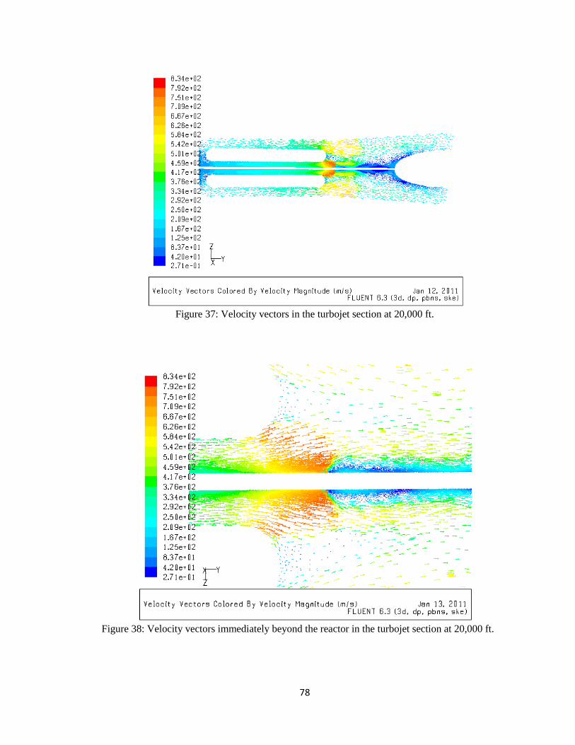
78
Figure 37: Velocity vectors in the turbojet section at 20,000 ft.
Figure 38: Velocity vectors immediately beyond the reactor in the turbojet section at 20,000 ft.

79
Figure 39: Velocity vectors entering the turbine portion of the turbojet section at 20,000 ft.
Figure 40: Static pressure in the turbofan section at 40,000 ft.

80
Figure 41: Static pressure in the turbojet section at 40,000 ft.
Figure 42: Static temperature in the turbofan section at 40,000 ft.
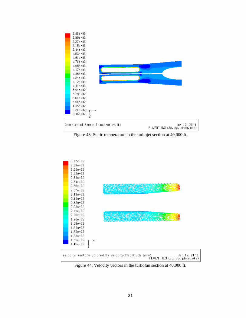
81
Figure 43: Static temperature in the turbojet section at 40,000 ft.
Figure 44: Velocity vectors in the turbofan section at 40,000 ft.

82
Figure 45: Velocity vectors in the turbojet section at 40,000 ft.
Figure 46: Static pressure in the turbofan section at 60,000 ft.

83
Figure 47: Static pressure in the turbojet section at 60,000 ft.
Figure 48: Static temperature in the turbofan section at 60,000 ft.
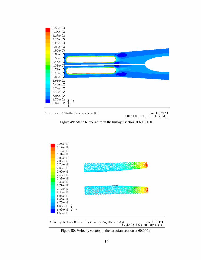
84
Figure 49: Static temperature in the turbojet section at 60,000 ft.
Figure 50: Velocity vectors in the turbofan section at 60,000 ft.

85
Figure 51: Velocity vectors in the turbojet at 60,000 ft.
Table 4 shows the data from all of the simulations completed at the various
altitudes. The maximum temperature values show the need for heat-treated materials
used inside the reactor chamber. The mass flow rates are inputs based on the density,
velocity, and cross-sectional area of the engine. These flow rates also take into account
the inlet fan in front of the engine. The thrust values are listed in Table 4 to compare
with the thrust capability of the current engine. Given that the thrust of the current
engine is 42 kN, the new engine compares quite well considering that approximately half
of the mass from the jet fuel is eliminated. Although the maximum thrust capability of
the new engine does not reach 42 kN, the new max thrust of 23.4 kN creates a larger
thrust-to-weight ratio (0.463) than the current engine (0.355). Therefore, the new engine

86
would work just as well as the current engine given that half of the take-off mass is
eliminated.
Table 4: Data from all of the simulations.
Altitude
(ft*1000) turbojet (kg/s) turbofan (kg/s) Maximum Temperature
of air (K)
Thrust
(kN)
Ground (0 ft) 90 225 1520 23.4
20 80 200 867 22.6
40 50 125 897 15.9
60 30 75 830 10.0

87
CHAPTER VIII
CONCLUSION
Based on the results from the comparisons of similar propulsion systems, CFD
models, and history of nuclear research, it is shown that a nuclear turbine engine is a
viable option to replace the gas turbine engine. More than half of the current Global
Hawk‟s wet mass is fuel, and this amount of fuel lasts about 100 hours. Fossil fuels can
only produce a small amount of power compared to nuclear energy. A nuclear turbine
engine can outperform the gas turbine, internal combustion, and solar electric propulsion
systems. From the previous history of nuclear airplane research, the Global Hawk can
successfully implement a nuclear turbine engine if the funding is adequate. Although
radiation can affect the materials and systems on the Global Hawk, there are no emissions
from the fuel itself. The CFD models show that the nuclear turbine engine has a higher
thrust to weight ratio than the current Rolls-Royce engine. Nuclear fuels are the future
for power production, and a military UAV would be a great start towards future research.
The big decision is whether the cost of keeping constant surveillance on a region for a
year or more is economically viable, and this determination falls on the US Congress and
the military.

88
Future Work
Most of the current research in airplane propulsion systems is aimed at improving
the efficiency of the current systems as opposed to designing replacements. There is also
research in improving fuel injection to improve thermal efficiency. Although the Carnot
efficiency of gas turbine engines is around 60 percent, the thermal efficiency from the
fuel is between 30 and 35 percent. Material science is also a main object of research for
gas turbine and internal combustion engines. Improving thermal coatings for materials in
the combustion chamber can increase the maximum operating temperature. This can
increase the efficiency or performance of the engine by increasing the maximum
temperature in the combustion chamber. For nuclear engines, a large amount of research
is still needed before it can be implemented. It is possible to use the nuclear reactor in a
ramjet engine so that the compressor and turbine can be completely eliminated.
Alternative materials also need to be researched in order to make a nuclear turbine engine
successful because a 2500K reactor needs to be attached to the central shaft through the
support of bearings.
In light of the need for stronger materials, some futuristic designs have been
suggested. One of these futuristic designs is the exo-skeletal engine from NASA. The
exo-skeletal engine is a bit different from a conventional gas turbine engine in that the
central shaft does not rotate. The compressor and turbine blades are attached to the
engine skirt on the outside, and every other row of consecutive blades is stationary. This
particular engine still has a bypass where most of the air entering the inlet does not pass
through the combustion chamber. The benefit of using this type of design is the ability to
use lighter materials with lower tensile strength. Ceramics have never been used in gas

89
turbine engines because of their poor toughness and tensile strength. However, it is
theorized that an exo-skeletal engine could use ceramics because the forces are in
compression instead of tension. Some problems with such a design include the bearings
between the engine skirt and the rotating compressor and turbine blades as well as the
maintenance. Most futuristic engine designs like the exo-skeletal engine are still in early
design stages and need years of research before implementation.

90
REFERENCES
Aerospaceweb.org. “Pentagon & Boeing 757 Engine Investigation.” 2010.
dddddd<http://www.aerospaceweb.org/question/conspiracy/q0265.shtml>
Angelo, Joseph A, and Buden, David. Space Nuclear Power. Malibar, Florida: Orbit
ddddddBook Company, Inc, 1985.
Argonne National Laboratory (ANL). “Uranium Quick Facts.” 2011.
dddddd<http://web.ead.anl.gov/uranium/guide/facts/>
Averro, Eagle. “RTG Nuclear Power How Safe?” 2007.
Dddddd<http://s220.photobucket.com/albums/dd189/Eagle_Averro/Nuclear%20Power/?
ddddddaction=view¤t=200px-RTG-CassiniT.jpg>
“Basics of Solar Energy” December, 2009.
dddddd<http://zebu.uoregon.edu/disted/ph162/l4.html>
Beach, General Sir Hugh, Crossland, Dr Ian, Cowley, Roger, Harris, Dr Jack, and
ddddddWatson, Dr Christopher. The Management of Separated Plutonium in the UK.
ddddddLondon, England: British Pugwash Group, November 2009.
Black, Mike and Gutro, Rob. “NASA's Global Hawk Drone Aircraft Flies Over Frank on
ddddddthe GRIP Hurricane Mission.” National Aeronautics and Space Administration
ddddddand National Oceanic and Atmospheric Administration: Sept 1, 2010.
dddddd<http://www.nasa.gov/mission_pages/hurricanes/missions/grip/news/frank-
ddddddflyover.html>
“Brief History of UAV‟s” University of Florida: LIST Lab, January 17, 2003.
< http://www.list.ufl.edu/uav/UAVHstry.htm>
Coifman, Benjamin, McCord, Mark R, Mishalani, Rabi, Morris, Steve, Redmill, Keith,
ddddddand Ozguner, Umit. “Traffic Surveillance from an Uninhabited Aerial Vehicle.”
ddddddThe Ohio State University, 2005.
Colon, Raul. “Flying on Nuclear, The American Effort to Built a Nuclear Powered
ddddddBomber.” The Aviation History On-Line Musem. August 6, 2007.
dddddd<http://www.aviation-history.com/articles/nuke-american.htm>

91
Dewar, James A. To the End of the Solar System. Lexington, Kentucky: The University
ddddddPress of Kentucky, 2004.
Dighera, Larry. “AC Propulsion SoLong UAV Flies for 48 Hours on Sunlight Two
ddddddNights Aloft Opens New Era of Sustainable Flight.” Electronics Point, October
dddddd2005. <http://www.electronicspoint.com/solong-solar-electric-uav-48-hour-flight-
ddddddt182817.html>
El-Genk, Mohamed S, and Tournier, Jean-Michel. “An Analysis of Coated Particles Fuel
ddddddCompact-General Purpose Heat Source (CPFC-GPHS).” Progress in Nuclear
ddddddEnergy. Vol 44, Issue 3. Elsevier Ltd, 2004.
Encyclopedia Britannica. “Gasoline Engines.” 2007.
dddddd<http://www.britannica.com/EBchecked/topic/226592/gasoline-engine>
Ford, Daniel. “B-36: Bomber at the Crossroads.” Air & Space Magazine. April 1, 1996.
<http://www.airspacemag.com/history-of-flight/B-36-Bomber-at-the-
ddddddCrossroads.html>
Gantz, Kenneth, ed. Nuclear Flight: The United States Air Force Programs for Atomic
ddddddJets, Missiles, and Rockets. Duell, Sloan, and Pearce: New York, NY, 1960.
Ibsen, Kelly. “Investigation of Byproduct Application of Jet Fuel.” National Renewable
ddddddEnergy Lab,October 2001. <http://www.nrel.gov/docs/fy02osti/30611.pdf>
Jordan, W.H, Cromer, S.J, and Miller, A.J. “Aircraft Nuclear Propulsion Project
ddddddQuarterly Progress Report For Period Ending March 31, 1957.” Oak Ridge
ddddddNational Laboratory. July 5, 1957.
Kulcinski, G.L. “Nuclear Thermal Rockets.” Rawlings-SAIC. Mar 22-24, 2004.
La Francha, Peter. “First Italian solar powered UAV makes debut flights.” Flightglobal,
ddddddOctober 2007.<http://www.flightglobal.com/articles/2007/10/22/218665/first-
dddddditalian-solar-powered-uav-makes-debut-flights.html>
Lis, Krzysztof. “Ideal and Real Brayton Cycle on a T-S Diagram.” December, 2006.
dddddd<commons.wikimedia.org/wiki/Category:Brayton_cycle>
Matej. “Nuclear HTRE Propulsion.” March 14, 2005.
<http://www.abovetopsecret.com/forum/thread126597/pg1>
92
Oates, Gordon C. Przemienieck, J.S, ed. Aerothermodynamics of Gas Turbine and
ddddddRocket Propulsion, Third Edition. Reston, VA: AIAA, 1997.
Parsch, Andreas. “Vought SLAM.” <http://www.astronautix.com/lvs/slam.htm>
Patzek, Tad W. “Typical Heat Values for Various Fuels.” UC Berkeley, 2003.
dddddd<http://petroleum.berkeley.edu/patzek/ce24/Spring2003/heatvalues.htm>
Platform389. “The Weapon from Hell.” vBulletin Solutions, Inc, March 2004.
<http://www.militaryphotos.net/forums/showthread.php?27977-The-Weapon-
ddddddFrom-Hell>
Roche, Joseph M, Palac, Donald T, Hunter, James E, Myers, David E, Synder,
ddddddChristopher A, Kosareo, Daniel N, McCurdy, David R, Dougherty, Kevin T.
dddddd“Investigation of Exoskeletal Engine Propulsion System Concept.” NASA Glenn
ddddddResearch Center, August 2005.
Rolls-Royce. “AE 3007-Power for the Global Hawk and EMB 145 Special Versions.”
dddddd2006. <http://www.rolls-royce.com/Images/ae3007_tcm92-6713.pdf>
Sandia National Laboratories (SNL). “Gallium Arsenide Solar Cells.” Sandia National
ddddddLaboratories, 2002.
Ddddd<http://photovoltaics.sandia.gov/docs/PVFSCGallium_Arsenide_Solar_Cells.htm>
Stacy, Susan M. A History of the Idaho National Engineering and Environmental
ddddddLaboratory, 1949-1999. Idaho National Laboratory, 2011.
dddddd<http://www.inl.gov/proving-the-principle/>
Stoffel, Jesse. “Dreams of Nuclear Flight: The NEPA and ANP Programs.” University of
ddddddWisconsin-Madison. May 10, 2000.
ThinkQuest. “1942 Fermi‟s Nuclear Reactor.” 1999.
dddddd<http://library.thinkquest.org/27954/Fermi.html>
“Types of Air-Breathing Engines.” Cislunar Aerospace, Inc, 1998.
Dddddd<http://wings.avkids.com/Book/Propulsion/advanced/types-01.html>
United States Air Force. “Convair NB-36H „The Crusader.‟ ” 2010.
dddddd<http://www.nationalmuseum.af.mil/factsheets/factsheet.asp?id=2556>
United States Air Force. “MQ-1 Predator.” November, 2009.
Dddddd<http://www.af.mil/information/factsheets/factsheet.asp?fsID=122>

93
United States Air Force. “RQ-4 Global Hawk.” November, 2009.
Dddddd<http://www.af.mil/information/factsheets/factsheet.asp?fsID=13225&page=2>
World Nuclear Association. “What is Uranium?” February, 2011.
dddddd<http://www.world-nuclear.org/education/uran.htm>
York, Herb. Race to Oblivion: A Participant‟s View of the Arms Race. New York: Simon
ddddddand Schuster, 1970.