numerical analysis of convection along hot surface …€¦ · 1,2e-mail address:...
TRANSCRIPT
Available online at www.worldscientificnews.com
WSN 87 (2017) 150-162 EISSN 2392-2192
Numerical analysis of convection along hot surface of equipment in the selected boiler room
Robert Cichowicz1 & Artur Wacław Stelęgowski2
Department Environmental Engineering and Building Construction Installations, Faculty of Architecture, Civil and Environmental Engineering, Lodz University of Technology,
Al. Politechniki 6, 90-924 Lodz, Poland
1,2E-mail address: [email protected] , [email protected]
Phone +48 42 631 20 20, Fax +48 42 631 35 16
ABSTRACT
The combustion processes, that are taking place in combustion units in boiler plants, result in
heat production. Some of the heat is being exchanged between the thermal installation equipment and
the air in such type of a room. In consequence, both the temperature of equipment’s surface and of the
indoor air rises. This results in natural convection effect, in which the air heated up from the
equipment rises upwards (along with that part of the heat generated by combustion), and in its place
flows the air of lower temperature. As a result of the phenomenon, there is a change in airflow in the
room and a removal of part of heat gains from equipment. The numerical analysis of convection along
hot surface of technological facilities and equipment was made on the basis of the numerical
calculations of air parameters in the selected boiler room. Boundary conditions for the calculations
were determined using the results of building energy simulation and the results of experimental
measurements.
Keywords: boiler plant, air parameters, CFD technique
1. INTRODUCTION
Boiler plants are buildings equipped with thermal installations, in which the process of
fuel combustion is taking place and results in generation of heat [1-3]. Afterwards, the heat is

World Scientific News 87 (2017) 150-162
-151-
distributed to the receiver, e.g. heating installation. The heat generation and distribution is
associated with losing heat that is being exchanged between the installation elements and air
in the room [4-6]. Unfortunately, thermal insulation of the technological equipment and pipes
does not provide full hermeticity of the process, which results in an increase in the surface
temperature of the equipment and transfer of heat to the indoor air. A source of heat losses of
the thermal system in a boiler room is not only a furnace or boiler, but also linked facilities
and equipment, such as heat exchangers, filters, chimneys and pipes. Air heats up from the
equipment and goes up along with a part of the heat produced during combustion process.
And in its place flows air of lower temperature. This phenomenon is called natural convection
and results from a difference in the fluid densities [7]. The motion of air can be also made by
an external devices, such as ventilation fans, and this mechanism is called a forced convection
[8]. Convection of air around hot surfaces of technological equipment causes local
disturbances in the air temperature and velocity distribution. Cognition of these changes
allows to determine the effect of the thermal system on the heat conditions in the boiler room
[9].
The analysis of a convection is possible using the knowledge of the air temperature and
velocity distribution, the determination of which is based on experimental measurements or
numerical calculations. The numerical calculations of the air parameters [10-11] can be based
on the computational fluid dynamic methods (CFD), supported by inter alia the computer
programs such as: Ansys Fluent, AutoCAD CFD or Design Builder. The CFD analysis
software can be used for modelling both the natural convection [12-14] and the forced
convection [15-17], as well as the thermal processes occurring inside the combustion units
[18-20]. The results of calculations of the air parameters in the surroundings of the thermal
equipment constitute a basis for the interpretation of the physical phenomena that is resulting
from a combustion process taking place in the boiler plant.
2. RESULTS
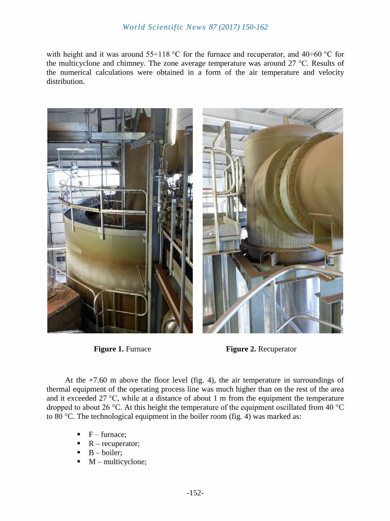
The boiler room analyzed is located in the city over 500,000 inhabitants (in Lodz), in
central Poland. Height of the boiler room is approximately 16.90 m. The thermal installation
consists of two independent, symmetrical process lines each of which contains inter alia
industrial furnace (fig. 1), recuperator (fig. 2), multicyclone (fig. 3) and chimney. The
temperature of the thermal process in the furnace is 870 °C and the maximum thermal power
of the installation is 8.14 MW. There is a mechanical exhaust ventilation installed in the room
and implemented by roof fans, while the air supply is carried out by the air intakes mounted in
the external walls.
The numerical analysis of air parameters in surroundings of the thermal installation was
made using the DesignBuilder software with a CFD module. The basis for the calculations
was the execution of the geometrical model and introduction of boundary conditions into the
program. Boundary conditions were determined using results of the building energy
simulation and of the experimental measurements. Additionally, the operation of only one
technological line was assumed for the analysis purposes. The following parameters were
introduced into the computer program: surface temperature of the equipment (37.0 ÷ 117.6
°C), temperature of partitions (18.0 ÷ 33.3 °C), outdoor temperature (23.3
°C) and the
ventilation airflow (97,020 m3/h). Surface temperature of the installation elements rises along
World Scientific News 87 (2017) 150-162
-152-
with height and it was around 55÷118 °C for the furnace and recuperator, and 40÷60
°C for
the multicyclone and chimney. The zone average temperature was around 27 °C. Results of
the numerical calculations were obtained in a form of the air temperature and velocity
distribution.
. .
Figure 1. Furnace Figure 2. Recuperator
At the +7.60 m above the floor level (fig. 4), the air temperature in surroundings of
thermal equipment of the operating process line was much higher than on the rest of the area
and it exceeded 27 °C, while at a distance of about 1 m from the equipment the temperature
dropped to about 26 °C. At this height the temperature of the equipment oscillated from 40 °C
to 80 °C. The technological equipment in the boiler room (fig. 4) was marked as:
F – furnace;
R – recuperator;
B – boiler;
M – multicyclone;

World Scientific News 87 (2017) 150-162
-153-
FI – filter;
CH – chimney.
Figure 3. Multicyclone
Figure 4. Air temperature at + 7.60 m

World Scientific News 87 (2017) 150-162
-154-
In the fig. 5 the air velocity vectors were showed to indicate the flow of warm air heated
from the technological equipment (at the +12.70 m level). The convection phenomena was
noticeable in the surroundings of the furnace and recuperator, where the air velocity was
around 0.50 ÷ 1.30 m/s and the air temperature above 32 °C. While over the multicyclone and
boiler it was 0.50 ÷ 0.70 m/s and 30 ÷ 32 °C. The dynamics of the removal of heat gains from
the equipment increased along with the temperature of its surface. Therefore, the highest air
velocities occurred near such installation elements as the furnace and the recuperator (surface
temperature of 105 °C and 118
°C), and the lowest near the chimney (60
°C). This is a positive
phenomenon in terms of the thermal comfort in the room, because of the removal of the heat
gains from the combustion units. However, the significant increase of the air velocity in the
working area can lead to draughts, which can be assessed negatively by workers staying in the
room [21-23].
Figure 5. Air temperature and velocity at + 12.70 m
In the cross-section of the non-operating process line (fig. 6), the air temperature and
velocity was not affected by the technological equipment. There was a stratification of air in
the room, which means that the air temperature rose along with height and was approximately
constant at the same level. The occurrence of this kind of air distribution was related to the
significant impact of natural convection that was not disrupted in this cross-section. The air
turbulence was very low and the air velocity in the most of the area (approximately 90%) was
below 0.30 m/s. However, some fluctuations occurred near the location of elements of the
ventilation system. Also, the air temperature varied locally. This was because the changes in
the air conditions in this part of the boiler room were due to impact of heat gains from the
operating process line and due to operation of the industrial ventilation. Therefore the local

World Scientific News 87 (2017) 150-162
-155-
increase of the air velocity above 1.00 m/s was caused by air supply through the air intakes in
the central part of the room and air exhaust through the roof fans.
Figure 6. Cross-section of the non-operating process line
In the cross-section of the operating process line (fig. 7), the air temperature and
velocity was much affected by operation of the boiler plant, and related heat gains. The
distribution of air temperature and velocity varied a lot in this cross-section. Significant
fluctuations of air parameters occurred in the vicinity of the ventilation elements as well as of
the technological equipment. The highest air temperatures (over 35 °C) were noticed above
the furnace and recuperator, which were the biggest sources of heat gains in the room. The
highest air velocities (over 1.00 m/s) were related to the operation of the ventilation system
and occurred near the location of air supply through the air intakes and air exhaust through the
roof fans. The convection streams occured in the case of the air heated up from the hot
surfaces of the technological equipment, which rose upwards along with a part of the heat
generated by combustion. The air velocity related to the convection phenomena exceeded
0.70 m/s in surroundings of the multicyclone, boiler, recuperator and furnace. However, the
stratification of air occurred only in the part of the boiler room with no combustion units.
In the cross-section A of the room (fig. 8), the air in surroundings of the operating
recuperator had a velocity of 0.27 ÷ 0.73 m/s and near the non-operating process line of below
0.27 m/s. Despite the air in the boiler room was exhausted by mechanical ventilation, there
was no significant influence of the operation of roof fans on the air velocity in the vicinity of
technological equipment. Therefore, it can be concluded that the influence of natural
convection caused an increase in the air velocity of approximately 0.50 ÷ 1.00 m/s (fig. 5).

World Scientific News 87 (2017) 150-162
-156-
Figure 7. Cross-section of the operating process line
Figure 8. Air velocity in the cross-section A
World Scientific News 87 (2017) 150-162
-157-
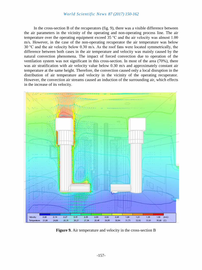
In the cross-section B of the recuperators (fig. 9), there was a visible difference between
the air parameters in the vicinity of the operating and non-operating process line. The air
temperature over the operating equipment exceed 35 °C and the air velocity was almost 1.00
m/s. However, in the case of the non-operating recuperator the air temperature was below
30 °C and the air velocity below 0.30 m/s. As the roof fans were located symmetrically, the
difference between both cases in the air temperature and velocity was mainly caused by the
natural convection phenomena. The impact of forced convection due to operation of the
ventilation system was not significant in this cross-section. In most of the area (70%), there
was air stratification with air velocity value below 0.30 m/s and approximately constant air
temperature at the same height. Therefore, the convection caused only a local disruption in the
distribution of air temperature and velocity in the vicinity of the operating recuperator.
However, the convection air streams caused an induction of the surrounding air, which effects
in the increase of its velocity.
Figure 9. Air temperature and velocity in the cross-section B

World Scientific News 87 (2017) 150-162
-158-
In the cross-section C of room, related to the location of multicyclones (fig. 10), there
was a significant movement of air of low temperature (23.3 °C) supplied at the bottom of the
operating multicyclone, and a movement of air of higher temperature (30 °C) that rose from
its upper surface due to occurrence of convection. The flow of the air supplied through the air
intake with the velocity exceeding 1.50 m/s was caused by forced convection due to the
operation of exhaust fans located on the roof of the building. High speed of supplied air
caused a local turbulence of the air at the lower parts of the technological equipment.
However, the air movement over the operating multicyclone was caused by a natural
convection of warm (above 30 °C) air heated up from surface of the equipment. The rest of
the cross-section area, where impact of the air supply stream and hot surfaces was minute, had
a distribution of air characteristic for the stratification. In most of the area (70%), the air
velocity was below 0.30 m/s and the temperature was approximately constant at the same
height of the room.
Figure 10. Air temperature and velocity in the cross-section C

World Scientific News 87 (2017) 150-162
-159-
This means that the disruptions in air temperature and velocity occurred only locally,
that is in the line of the air supply and over the operating facilities and equipment.
Nevertheless, the convection air streams caused an induction of the surrounding air.
Also, in the cross-section D of the room (fig. 11), the air near the operating chimney had
a higher velocity than in the rest of the area. The increase of air speed was conjunct with an
increase of air temperature near the chimney. Heat gains from hot (around 60 °C) surface of
the operating chimney were causing an increase of temperature of the surrounding air over
30 °C and velocity over 0.70 m/s. The convection phenomena caused that the air of lower
temperature (23.3 °C) flowed at the bottom of the chimney with low speed (approximately
0.10 m/s) and the air of higher temperature (above 30 °C) was exhausted at the top of the
room with high speed (over 0.70 m/s). Whereas, in the vicinity of non-operating chimney, as
well as in the most of the area, the velocity was below 0.20 m/s. However, at the bottom of
the room the air velocity exceeded 0.30 m/s, which was associated with an impact of supplied
air and related induction of air in the room.
Figure 11. Air temperature and velocity in the cross-section D

World Scientific News 87 (2017) 150-162
-160-
3. CONCLUSIONS
High temperature of the combustion process in the boiler room analysed was causing
the increase of surface temperature of elements of the combustion plant. As a consequence, a
convection of air heated from the equipment occurred, resulting in a disruption of the air
temperature and velocity distribution. By the temperature of 60 °C of installation elements,
the air temperature was approximately 30 °C and the velocity 0.70 m/s. While by the
temperature 118 °C of the furnace, the air temperature exceeded 32
°C and the velocity was
above 1.30 m/s. The difference between the air speed near the operating and non-operating
process line was up to 1.00 m/s (fig. 5).
This means that the occurrence of the convection phenomenon in the surroundings of
the thermal installation had positively affected the removal of heat gains related to the
combustion processes. This is because the air velocity increased along with the temperature of
the equipment. In addition, the natural convection had supported the industrial ventilation, the
aim of which was to remove the contamination and heat derived from the combustion process
[24-26]. What is more, providing better thermal conditions in a room effects in greater
thermal comfort sensations of the workers [27-29]. On the other hand, the disruptions of the
air temperature and velocity occurred mostly in the vicinity of operating technological
equipment and near the location of ventilation elements, such as air intakes and roof fans. In
most of the area, the air temperature was approximately constant at the same height and the
air velocity was below 0.30 m/s, which indicates for air distribution characteristic for
stratification. Therefore, the convection occurred in the whole boiler room, with a strong
fluctuation of air parameters in the surroundings of the operating boiler plant elements and
stable temperature and velocity in the rest of the area.
Understanding an influence of operation of combustion plant on thermal conditions in a
boiler room is related to knowledge of the temperature and air velocity distribution.
Convection and other thermal phenomena can be modelled using numerical methods [12-17],
which allow to determine the air parameters at any point of the room. Therefore, the CFD
methods are widely used in the analysis of heat transfer issues [11,18-20].
References
[1] Ch. Yin, L. Rosendahl, S. K. Kær, S. Clausen, S. L. Hvid, T. Hille, Energy Fuels 22 (2)
(2008) 1380–1390, DOI:10.1021/ef700689r
[2] Ch. Yin, L. Rosendahl, S. Clausen, S. L. Hvid, Energy 41 (1) (2012) 473-482,
https://doi.org/10.1016/j.energy.2012.02.050
[3] S. Rudra, L. Rosendahl, M. B. Blarkeb, Energy Conversion and Management 106
(2015) 1276-1285, https://doi.org/10.1016/j.enconman.2015.10.072
[4] D. H. Lee, S. Kwon, Journal of Micromechanics and Microengineering 12 (5) (2002)
670-676 , DOI:10.1088/0960-1317/12/5/324
[5] C. L. Hackert, J. L. Ellzey, O. A. Ezekoye, Combustion and Flame 112 (1-2) (1998) 73-
84, https://doi.org/10.1016/S0010-2180(97)81758-0
World Scientific News 87 (2017) 150-162
-161-
[6] J. Daou, M. Matalon, Combustion and Flame 128 (4) (2002) 321-339,
https://doi.org/10.1016/S0010-2180(01)00362-5
[7] A. Faghri, Y. Zhang, J. Howell, Advanced Heat and Mass Transfer, Global Digital
Press (2010).
[8] A. P. Hatton, D. D. James, H. W. Swire, Journal of Fluid Mechanics 42 (1) (1970) 17-
31, https://doi.org/10.1017/S0022112070001040
[9] R. Cichowicz, A. W. Stelegowski, Acta Innovations 23 (2017) 51-61
[10] Y. Ji, M.J. Cook, V. Hanby, Building and Environment 42 (3) (2007) 1158-1172,
https://doi:10.1016/j.buildenv.2005.11.002
[11] R. Cichowicz, A. Lewandowska, World Scientific News 73 (1) (2017) 72-79
[12] D. E. Glass, A. D. Dilley, H. Neale Kelly, Journal of Spacecraft and Rockets 38 (1)
(2001) 15-20, https://doi.org/10.2514/2.3666
[13] L.C. Wrobel, D.B. De Figueiredo, International Journal of Numerical Methods for Heat
& Fluid Flow, 1 (1) (1991) 3-18, https://doi.org/10.1108/eb017470
[14] A. Bermudez, M. R. Nogueiras, C. Vázquez, SIAM J. Numer. Anal. 44 (5) 2006, 1854–
1876, https://doi.org/10.1137/040615109
[15] J. R. Lloyd, E. M. Sparrow, International Journal of Heat and Mass Transfer 13 (2)
(1970) 434-438, https://doi.org/10.1016/0017-9310(70)90119-5
[16] T. Zhao, P. Cheng, International Journal of Heat and Mass Transfer 38 (16) (1995)
3011-3022, https://doi.org/10.1016/0017-9310(95)00017-4
[17] H. Abbassi, S. Turki, S. B. Nasrallah, International Journal of Thermal Sciences 40 (7)
(2001) 649-658, https://doi.org/10.1016/S1290-0729(01)01254-6
[18] Ch. R. Choi, C. N. Kim, Fuel 88 (9) (2009) 1720-1731,
https://doi.org/10.1016/j.fuel.2009.04.001
[19] N. Nikolopoulos, A. Nikolopoulos, E. Karampinis, P. Grammelis, E. Kakaras, Fuel 90
(1) (2011) 198-214, https://doi.org/10.1016/j.fuel.2010.08.007
[20] C. L. Yeh, International Journal of Heat and Mass Transfer 59 (2013) 172-190,
https://doi.org/10.1016/j.ijheatmasstransfer.2012.12.020
[21] N. Djongyang, R. Tchinda, D. Njomo, Renewable and Sustainable Energy Reviews 14
(9) (2010) 2626-2640, https://doi.org/10.1016/j.rser.2010.07.040
[22] M. Krajcik, R. Tomasi, A. Simone, B. W. Olesen, Science and Technology for the Built
Environment 22 (3) (2016), 317-317, http://doi.org/10.1080/23744731.2016.1131568
[23] B. W. Olesen, K. C. Parsons, Energy and Buildings 34 (6) (2002) 537-548,
https://doi.org/10.1016/S0378-7788(02)00004-X
[24] R. Cichowicz, G. Wielgosiński, A. Targaszewska, ECOL CHEM ENG S. 23 (1) (2016)
49-60, https://doi.org/10.1515/eces-2016-0003
[25] Y. Huang, Y. Wang, X. Ren, Y. Yang, J. Gao, Y. Zou, Energy and Buildings 128
(2016) 834–844, https://doi.org/10.1016/j.enbuild.2016.07.046

World Scientific News 87 (2017) 150-162
-162-
[26] A. C. Caputo, P. M. Pelagagge, Applied Thermal Engineering 29 (2009) 3204–3211,
https://doi.org/10.1016/j.applthermaleng.2009.04.025
[27] R. de Dear, G. S. Brager, Int J Biometeorol 45 (2001) 100–108
[28] N. M. Pinto, A. A. P. Xavier, K. Hatakeyama, Procedia Manufacturing 3 (2015) 4999–
5006, DOI:10.1016/j.promfg.2015.07.662
[29] A. Yousef, M. Arif, M. Katafygiotou, A. Mazroei, A. Kaushik, E. Elsarrag,
International Journal of Sustainable Built Environment 5 (1) (2016) 1–11,
https://doi.org/10.1016/j.ijsbe.2016.03.006
( Received 20 September 2017; accepted 10 October 2017 )