numerical analysis of open-centre ducted tidal turbines · march 30, 2012 oxford tidal energy...
TRANSCRIPT

UNIVERSITY OF OXFORD DEPARTMENT OF ENGINEERING SCIENCE CIVIL AND OFFSHORE ENGINEERING TIDAL ENERGY RESEARCH GROUP
Numerical Analysis of Open-Centre Ducted Tidal Turbines
Clarissa Belloni, Richard Willden & Guy Houlsby

March 30, 2012 Oxford Tidal Energy Workshop
C.S.K.Belloni, R.H.J.Willden & G.T.Houlsby Numerical Analysis of Open-Centre Ducted Tidal Turbines
Goal of project
Goal: Understanding the fluid mechanics
of open-centre ducted turbines
Methodology: § CFD simulation; § Analysis of fluid mechanics; § Relate fluid mechanics to device performance.

March 30, 2012 Oxford Tidal Energy Workshop
C.S.K.Belloni, R.H.J.Willden & G.T.Houlsby Numerical Analysis of Open-Centre Ducted Tidal Turbines
I. Overview: Open-centre ducted tidal turbine devices
Advantage claims: • speed up effect with power increase • improved flow alignment
OpenHydro
Clean Current
Main disadvantage: • increased material • reduced turbine area

March 30, 2012 Oxford Tidal Energy Workshop
C.S.K.Belloni, R.H.J.Willden & G.T.Houlsby Numerical Analysis of Open-Centre Ducted Tidal Turbines
I. Overview of investigation
Bare turbine Open-centre turbine
• method validation • baseline case • low and high blockage • yawed inflow
• low blockage • various aperture diameters • yawed inflow

March 30, 2012 Oxford Tidal Energy Workshop
C.S.K.Belloni, R.H.J.Willden & G.T.Houlsby Numerical Analysis of Open-Centre Ducted Tidal Turbines
Blockage ratio, B = 3.5%,
II. Method validation: Simulation Setup
Numerical simulations: • FLUENT (numerical solver, solving RANS equations); • Turbine modelled as porous disc; • Constant uniform inflow; • no hydrostatic pressure variation; • Symmetry condition at domain boundaries; • Steady & unsteady flow simulations.
BRIEF ARTICLE
THE AUTHOR
(1) CP =power extracted from fluid
power available for extraction= 4a(1− a)2
(2) CP =P
1
2ρAfrontalU
3∞
(3) CT =T
1
2ρAfrontalU
2∞
(4) B =Afrontal
Achannel
(5) Ut = U∞(1− a)
(6) CP =power extracted from fluid
power available for extraction= 4a(1− a)2
1

March 30, 2012 Oxford Tidal Energy Workshop
C.S.K.Belloni, R.H.J.Willden & G.T.Houlsby Numerical Analysis of Open-Centre Ducted Tidal Turbines
II. Method validation: Bare turbine
3D simulation of bare disc: Good agreement with Linear Momentum Actuator Disc Theory (LMADT) corrected for blockage effect*.
*Houlsby et al. (2008): “Application of Linear Momentum Actuator Disc Theory to Open Channel Flow”
BRIEF ARTICLE
THE AUTHOR
(1) CP =power extracted from fluid
power available for extraction= 4a(1− a)2
(2) CP =P
1
2ρAfrontalU
3∞
(3) CT =T
1
2ρAfrontalU
2∞
(4) B =Afr
Achannel
(5) Ut = U∞(1− a)
(6) CP =power extracted from fluid
power available for extraction= 4a(1− a)2
1
BRIEF ARTICLE
THE AUTHOR
(1) CP =power extracted from fluid
power available for extraction= 4a(1− a)2
(2) CP =P
1
2ρAfrontalU
3∞
(3) CT =T
1
2ρAfrontalU
2∞
(4) B =Afr
Achannel
(5) Ut = U∞(1− a)
(6) CP =power extracted from fluid
power available for extraction= 4a(1− a)2
1
BRIEF ARTICLE
THE AUTHOR
(1) CP =power extracted from fluid
power available for extraction= 4a(1− a)2
(2) CP =P
1
2ρAfrontalU
3∞
(3) CT =T
1
2ρAfrontalU
2∞
(4) B =Afr
Achannel
(5) Ut = U∞(1− a)
(6) CP =power extracted from fluid
power available for extraction= 4a(1− a)2
1
DRAFT0 0.3 0.6 0.9 1.2 1.5 1.80
0.2
0.4
0.6
0.8
1
CT
CP
LMADT, B=0.035
LMADT, B=0.2
CFD, B=0.035
CFD, B=0.2
Figure 4: Performance of the bare turbine, CP vs. CT , for blockage ratios of B = 0.035 and B = 0.2 for both
CFD and LMADT for confined flow.
point remix with the by-pass flow. The process introduces further, unavoidable en-
ergy removal from the flow. Additional energy removal is especially important when
comparing bare and ducted devices. The presence of a duct within the flow exerts an
additional thrust on the fluid. This added thrust can lead to significantly more energy
being extracted from the flow than is converted into useful energy. As tidal flows must
be considered as finite resources the total energy removed from the flow represents
an important feature of each device. Thus we introduce a device efficiency definition
which relates the useful power generated to the total power removed from the flow,
defined as the basin efficiency,
ηbasin =useful power
total power removed from the flow . (11)
To retrieve the total power removed from the flow we analyse the energy flux
through domain cross sections at various stages upstream and downstream of the tur-
bine; see Fig. 5.
At each streamwise plane the energy flux is calculated by integrating the product
of the total pressure, p0, and the streamwise velocity, ux, over the cross-sectional area,
11
BRIEF ARTICLE
THE AUTHOR
(1) CP =power extracted from fluid
power available for extraction= 4a(1− a)2
(2) CP =P
1
2ρAfrontalU
3∞
(3) CT =T
1
2ρAfrontalU
2∞
(4) B =Afrontal
Achannel
(5) Ut = U∞(1− a)
(6) CP =power extracted from fluid
power available for extraction= 4a(1− a)2
1

March 30, 2012 Oxford Tidal Energy Workshop
C.S.K.Belloni, R.H.J.Willden & G.T.Houlsby Numerical Analysis of Open-Centre Ducted Tidal Turbines
II. Method validation: Performance analysis
Power coefficient
Basin efficiency
BRIEF ARTICLE
THE AUTHOR
(1) CP =power extracted from fluid
power available for extraction
(2) CP =P
1
2ρAfrontalU
3∞
(3) CT =T
1
2ρAfrontalU
2∞
(4) B =Afrontal
Achannel
(5) Ut = U∞(1− a)
(6) CP =power extracted from fluid
power available for extraction= 4a(1− a)2
1
BRIEF ARTICLE
THE AUTHOR
(1) CP =useful power
kinetic flux available in upstream flow
(2) CP =P
1
2ρAfrontalU
3∞
(3) CT =T
1
2ρAfrontalU
2∞
(4) B =Afrontal
Achannel
(5) Ut = U∞(1− a)
(6) ηbasin =useful power
total power removed from the flow=
P
G(xinflow)−G(x∞)
1
BRIEF ARTICLE
THE AUTHOR
(1) CP =useful power
kinetic flux available in upstream flow
(2) CP =P
1
2ρAfrontalU
3∞
(3) CT =T
1
2ρAfrontalU
2∞
(4) B =Afrontal
Achannel
(5) Ut = U∞(1− a)
(6) ηbasin =useful power
total power removed from the flow=
P
G(xinflow)−G(x∞)
(7) ηbasin =P
G(xinflow)−G(x∞)
1
BRIEF ARTICLE
THE AUTHOR
(1) CP =useful power
kinetic flux available in upstream flow
(2) CP =P
1
2ρAfrontalU
3∞
(3) CT =T
1
2ρAfrontalU
2∞
(4) B =Afrontal
Achannel
(5) Ut = U∞(1− a)
(6) ηbasin =useful power
total power removed from the flow=
P
G(xinflow)−G(x∞)
(7) ηbasin =P
G(xinflow)−G(x∞)
1

March 30, 2012 Oxford Tidal Energy Workshop
C.S.K.Belloni, R.H.J.Willden & G.T.Houlsby Numerical Analysis of Open-Centre Ducted Tidal Turbines
III. Open-Centre Turbine
Various aperture diameters tested

March 30, 2012 Oxford Tidal Energy Workshop
C.S.K.Belloni, R.H.J.Willden & G.T.Houlsby Numerical Analysis of Open-Centre Ducted Tidal Turbines
III. Open-Centre Turbine: Flow Field
Flow features: • No large scale separation on duct exterior
• Jet flow through the aperture of the turbine
Increased thrust: • Reduced jet velocity
• Reduced disc velocity
• Increase in Δp
DRAFT3.2. Thrust Analysis
When examining the thrust on a device we need to consider not only the thrust on
the disc. The thrust on the duct (and on any support structures if these were modelled)
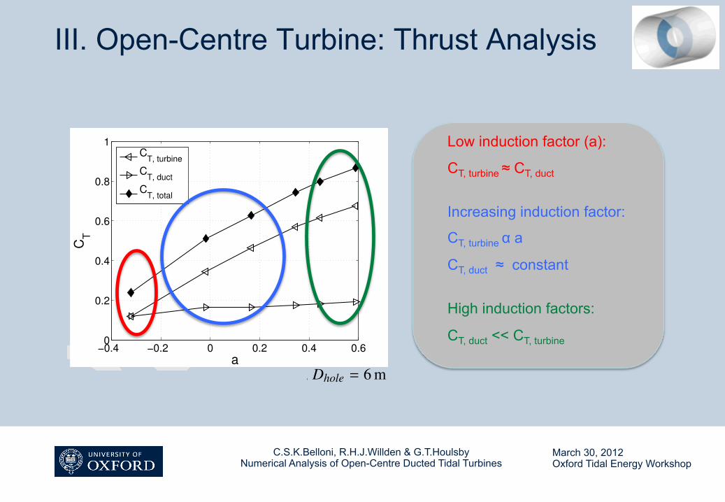
plays a significant role when assessing the thrust on the overall device. Fig. 13 shows
the thrust coefficient plotted as a function of the spatial mean of the induction factor.
Three thrust coefficients are plotted: CT = CT, turbine, the thrust coefficient for the
turbine disc (the standard thrust coefficient), CT, duct, coefficient for the thrust on the
duct, and CT, total, which is a sum of the two components CT, turbineand CT, duct.
Note that the duct inlet area is used in defining all three coefficients.
!0.4 !0.2 0 0.2 0.4 0.60
0.2
0.4
0.6
0.8
1
a
CT
CT, turbine
CT, duct
CT, total
Figure 13: Thrust coefficients for the open-centre turbine, Dhole = 6 m. All cases B = 0.035.
For very low induction factors, both thrust on duct and disc are of the same or-
der of magnitude. With increasing induction factor, the disc thrust, CT, turbine, in-
creases roughly linearly. While there is a small overall increase, the thrust on the duct,
CT, duct, remains constant over a broad range of induction factors. For high induction
factors the thrust on the duct is significantly smaller than the disc thrust.
22
increasing thrust
increasing thrust
March 30, 2012 Oxford Tidal Energy Workshop
C.S.K.Belloni, R.H.J.Willden & G.T.Houlsby Numerical Analysis of Open-Centre Ducted Tidal Turbines
III. Open-Centre Turbine: Thrust Analysis
DRAFT3.2. Thrust Analysis
When examining the thrust on a device we need to consider not only the thrust on
the disc. The thrust on the duct (and on any support structures if these were modelled)
plays a significant role when assessing the thrust on the overall device. Fig. 13 shows
the thrust coefficient plotted as a function of the spatial mean of the induction factor.
Three thrust coefficients are plotted: CT = CT, turbine, the thrust coefficient for the
turbine disc (the standard thrust coefficient), CT, duct, coefficient for the thrust on the
duct, and CT, total, which is a sum of the two components CT, turbineand CT, duct.
Note that the duct inlet area is used in defining all three coefficients.
!0.4 !0.2 0 0.2 0.4 0.60
0.2
0.4
0.6
0.8
1
a
CT
CT, turbine
CT, duct
CT, total
Figure 13: Thrust coefficients for the open-centre turbine, Dhole = 6 m. All cases B = 0.035.
For very low induction factors, both thrust on duct and disc are of the same or-
der of magnitude. With increasing induction factor, the disc thrust, CT, turbine, in-
creases roughly linearly. While there is a small overall increase, the thrust on the duct,
CT, duct, remains constant over a broad range of induction factors. For high induction
factors the thrust on the duct is significantly smaller than the disc thrust.
22
Low induction factor (a):
CT, turbine ≈ CT, duct
Increasing induction factor:
CT, turbine α a
CT, duct ≈ constant
High induction factors:
CT, duct << CT, turbine
DRAFT3.2. Thrust Analysis
When examining the thrust on a device we need to consider not only the thrust on
the disc. The thrust on the duct (and on any support structures if these were modelled)
plays a significant role when assessing the thrust on the overall device. Fig. 13 shows
the thrust coefficient plotted as a function of the spatial mean of the induction factor.
Three thrust coefficients are plotted: CT = CT, turbine, the thrust coefficient for the
turbine disc (the standard thrust coefficient), CT, duct, coefficient for the thrust on the
duct, and CT, total, which is a sum of the two components CT, turbineand CT, duct.
Note that the duct inlet area is used in defining all three coefficients.
!0.4 !0.2 0 0.2 0.4 0.60
0.2
0.4
0.6
0.8
1
a
CT
CT, turbine
CT, duct
CT, total
Figure 13: Thrust coefficients for the open-centre turbine, Dhole = 6 m. All cases B = 0.035.
For very low induction factors, both thrust on duct and disc are of the same or-
der of magnitude. With increasing induction factor, the disc thrust, CT, turbine, in-
creases roughly linearly. While there is a small overall increase, the thrust on the duct,
CT, duct, remains constant over a broad range of induction factors. For high induction
factors the thrust on the duct is significantly smaller than the disc thrust.
22

March 30, 2012 Oxford Tidal Energy Workshop
C.S.K.Belloni, R.H.J.Willden & G.T.Houlsby Numerical Analysis of Open-Centre Ducted Tidal Turbines
III. Open-Centre Turbine: Aperture
Flow features: • No large scale separation on duct exterior
• Jet flow through the open-centre of the turbine
Increased aperture: • Increased jet velocity
• Increased disc velocity
• small increase in Δp

March 30, 2012 Oxford Tidal Energy Workshop
C.S.K.Belloni, R.H.J.Willden & G.T.Houlsby Numerical Analysis of Open-Centre Ducted Tidal Turbines
III. Open-Centre Turbine: Performance
Power Power density
increasing aperture
• Power decreases with increasing aperture;
• Power density increases with increasing aperture;
• Basin efficiency only slightly influenced by disc aperture.

March 30, 2012 Oxford Tidal Energy Workshop
C.S.K.Belloni, R.H.J.Willden & G.T.Houlsby Numerical Analysis of Open-Centre Ducted Tidal Turbines
III. Open-Centre Turbine: Performance
Power
• Power decreases with increasing aperture;
• Power density increases with increasing aperture;
• Basin efficiency only slightly influenced by disc aperture.
Basin efficiency
increasing aperture

March 30, 2012 Oxford Tidal Energy Workshop
C.S.K.Belloni, R.H.J.Willden & G.T.Houlsby Numerical Analysis of Open-Centre Ducted Tidal Turbines
IV. Yawed Inflow
Bare and open-centre turbine analysed at various yaw angles

March 30, 2012 Oxford Tidal Energy Workshop
C.S.K.Belloni, R.H.J.Willden & G.T.Houlsby Numerical Analysis of Open-Centre Ducted Tidal Turbines
IV. Yawed Inflow: Flow Field
Bare turbine:
• Reduced projected frontal area
Open-centre turbine:
• Increased projected frontal area
• Flow straightening
DRAFT3.2. Thrust Analysis
When examining the thrust on a device we need to consider not only the thrust on
the disc. The thrust on the duct (and on any support structures if these were modelled)
plays a significant role when assessing the thrust on the overall device. Fig. 13 shows
the thrust coefficient plotted as a function of the spatial mean of the induction factor.
Three thrust coefficients are plotted: CT = CT, turbine, the thrust coefficient for the
turbine disc (the standard thrust coefficient), CT, duct, coefficient for the thrust on the
duct, and CT, total, which is a sum of the two components CT, turbineand CT, duct.
Note that the duct inlet area is used in defining all three coefficients.
!0.4 !0.2 0 0.2 0.4 0.60
0.2
0.4
0.6
0.8
1
aC
T
CT, turbine
CT, duct
CT, total
Figure 13: Thrust coefficients for the open-centre turbine, Dhole = 6 m. All cases B = 0.035.
For very low induction factors, both thrust on duct and disc are of the same or-
der of magnitude. With increasing induction factor, the disc thrust, CT, turbine, in-
creases roughly linearly. While there is a small overall increase, the thrust on the duct,
CT, duct, remains constant over a broad range of induction factors. For high induction
factors the thrust on the duct is significantly smaller than the disc thrust.
22
A frontal
A frontal

March 30, 2012 Oxford Tidal Energy Workshop
C.S.K.Belloni, R.H.J.Willden & G.T.Houlsby Numerical Analysis of Open-Centre Ducted Tidal Turbines
IV. Yawed Inflow: Performance
Power Basin efficiency

March 30, 2012 Oxford Tidal Energy Workshop
C.S.K.Belloni, R.H.J.Willden & G.T.Houlsby Numerical Analysis of Open-Centre Ducted Tidal Turbines
IV. Yawed Inflow: Performance • Increase in power coefficient for open-centre turbine (full disc and with aperture);
• Slight decrease in power coefficient for bare turbine;
• Steep drop in basin efficiency for open-centre turbine
Power Basin efficiency

March 30, 2012 Oxford Tidal Energy Workshop
C.S.K.Belloni, R.H.J.Willden & G.T.Houlsby Numerical Analysis of Open-Centre Ducted Tidal Turbines
V. Conclusions
Method validation: § Bare turbine simulations in good agreement with Linear Momentum Actuator Disc
Theory (LMADT). Open-centre turbine: § Jet flow through aperture increases mass flow and power density, but overall
performance in terms of power reduced significantly compared to the full disc.
Yawed inflow: • Increase in performance of the open-centre turbine due to increased effective blockage
and flow straightening, at the expense of decreased basin efficiency.

March 30, 2012 Oxford Tidal Energy Workshop
C.S.K.Belloni, R.H.J.Willden & G.T.Houlsby Numerical Analysis of Open-Centre Ducted Tidal Turbines
THANK YOU! QUESTIONS?