numerical modeling of a composite hollow vierendeel-truss · vierendeel-truss was performed, ......
TRANSCRIPT

Abstract—Composite trusses, a very efficient alternative to
overcome large spans for civil engineering, are usually constructed with corner sections, and in many cases, have a central Vierendeel panel, which the main objective is to enable the passage of pipes, unhampered in frames with the presence of diagonals. This work aims to study the feasibility and ultimate limit state to extend Vierendeel panels across the central third of the structure and replace the corner for hollow sections. The fundamental points that supported the theoretical calculation and, especially, how the numerical modeling of the composite Vierendeel-truss was performed, were indicated. The results showed that the regions of the structure with higher stress, determined by finite element method via software Ansys, were the same identified by the analytical calculation and bi-dimensional elastic modeling as acting the highest internal forces, thus validating the methodology of proposed calculation.
Index Terms—Composite truss, hollow structure, vierendeel panel.
I. INTRODUCTION The composite trusses, a very effective alternative to
overcome large spans in a building, are normally constructed with corner sections, and in many cases, contain a central Vierendeel panel, as shown in Fig. 1. The principle objective of this panel is the passing of pipes, normally difficult with the presence of diagonals.
steel deck reinforced slab
central Vierendeel panel Fig. 1. Composite truss with a central vierendeel panel.
The two main reasons of this work consist of replacing the
corner type sections of the composite trusses with hollow sections and check the feasibility to withdraw further diagonals, forming new Vierendeel panels in the central region of the structure.
The hollow sections existing currently in the construction industry are increasing their use in Brazil and worldwide, and their use in the specific case of composite trusses, can, in many cases, avoid, loss of stability problems commonly found in the calculation involving corner sections. Already
Manuscript received March 20, 2014; revised May 28, 2014. Augusto O. B. Silva is with the Campinas City Hall, SP, Brasil (e-mail:
[email protected]). Newton O. P. Júnior and João A. V. Requena are with Civil Engineering,
Architecture and Urbanism Faculty, Unicamp University, Campinas, SP 13083-852 Brasil (e-mail: [email protected], [email protected]).
taking away the diagonal allows the removal of weight and saving material and intensive labor, and free space for the passage of a greater number of pipes.
This new structure, here called a composite Vierendeel-truss, consists, in accordance with Fig. 2, of a reinforced concrete slab on a steel deck, supported by a flat metal structure composed of parallel chords and multiple Vierendeel panels in the central third of the span.
This article aims to indicate the fundamentals that supported the theoretical calculation and mainly shows how the modeling was performed via the finite element method of a composite Vierendeel-truss. For a better understanding of the work, the name of the members (TC1…TC8, D1…D5, V1…V7, BC1…BC7) and frames (1L…8) are shown in Fig. 3.
5 x 1000 mm 5 x 1000 mm5 x 1000 mm
1000 mm
Fig. 2. Dimensions of the composite vierendeel-truss.
TC1 T C2
D1 D2V1 V2
T C3 T C4 TC5 TC6 T C7
BC1
T C8
BC2 BC5BC3 BC4 BC6 BC7
V3 V4 V5 V6 V7D3 D4 D5
1L 2L 3L 4L 5L 6L 7L 8 Fig. 3. Names of the members and frames.
II. ULTIMATE LIMIT STATE The project developed maintained the horizontal shear on
the connectors, and the resistances of the slab, steel members and joints within safe limits, thus avoiding the undesirable ultimate limit states, which could lead to the composite structure breaking sharply. It was chosen a structural configuration and developed a thorough calculation that would guarantee the complete interaction between slab and upper chord and would cause ultimate state achieved with yielding of the bottom chord, as desired in the case of composite trusses.
The calculation of the required number of connectors, with positioning illustrated in Fig. 4, as well as verification of members resistance were performed according to [1]. To avoid stress concentration at the ends of the members it was chosen overlapping welded joints, and verifications were performed as in [2], including, all the valid conditions prescribed for the geometric relations between tubes. As the resistance of the welds is greater than the sections, and, assuming that they are well executed when building the structure, a hypothesis was considered of which the weld would not be a limit state.
Numerical Modeling of a Composite Hollow Vierendeel-Truss
Augusto O. B. Silva, Newton O. P. Júnior, and João A. V. Requena
176
IACSIT International Journal of Engineering and Technology, Vol. 7, No. 3, June 2015
DOI: 10.7763/IJET.2015.V7.788

7500 mm
196 mm
24 stud bolts
23 x 305 = 7015 mm289 mm
(D = 19 x 90 mm)
Fig. 4. Position of the stud bolts in the composite structure.
A steel deck MF-50 was used for the floor slab with a nominal thickness of 1.25 mm in accordance with [3]. The total thickness of the slab was 11 cm and the nominal resistances of concrete and hollow steel members were, respectively, fck = 2.5 kN/cm2 and fyk = 30 kN/cm2. An imposed load was applied of 5 kN/m2, which subjected the composite structure to a maximum bending moment of 849.94 kN.m.
The theoretical study determined that the dimensioning of the upper chord should be performed by loading the non-composite truss, and that the size of the lower chord, web members and number of stud bolts should be done by loading the composite truss, according to [1]-[4].
The introduction of the new Vierendeel panels, however, arise considerably local bending moments in the chords of the isolated truss and in the bottom chord of the composite truss. This phenomenon, which cannot be neglected during the design process, was analyzed from the perspective of the theory of composite beams with large web openings, as determined in [5].
The Vierendeel bending moments are highly dependent on the distribution of loads on the non-composite and composite structures, leading to application of two types of loading.
The moments were initially determined via hand analisys and then compared with the values indicated by two-dimensional elastic modeling performed with the aid of ftool software [6]. It built up the geometry of the structure and defined to each member the material, the cross-sectional area and moment of inertia. The connecting element between the upper chord and the slab was considered to be concrete, with moment of inertia calculated by a rectangular element with a width equal to the influence width of the slab and height equal to the average width of the rib.
The internal forces determined with these initial studies were finally confronted with the stresses presented by a numerical three-dimensional model, through software Ansys [7].
The step-by-step theoretical process with all the determined analytical values can be clearly checked in [8].
A. Loads and Internal Forces on the Isolated Steel Truss The non-composite truss was subjected to two types of
loading: throughout the full span and another one simulating the concreting process from the left support to the end of the frame 6R, as shown in Fig. 5. The highest values of bending moment and axial compression were detected in members TC6 (the underside of the top chord) and TC8. The internal forces obtained via analytical and ftool software calculation are shown in Table I, and the ratio between them shows that
the values obtained by elastic modeling were close to the calculated theoretical process.
Reference [1] indicates that the safety conditions to be met by welded hollow members subjected to the combined axial force and bending moment, loaded so that there is no torsion, are to be provided by the equations (1) and (2) where NSd and NRd are, respectively, the design normal force and design resistance to normal force, Mx,Sd and My,Sd are, respectively, the design bending moments about x and y axis, and, Mx,Rd and My,Rd are, respectively, the design resistances for bending moments about x and y axis.
TC6 TC6TC8
8.26 kN/m
1.07 kN/m
PL FL
Fig. 5. Steel truss partially loaded (PL) and fully loaded (FL).
If 0, 2 :Sd
Rd
NN
≥ ,,
, ,
8 1,09
y Sdx SdSd
Rd x Rd y Rd
MMNN M M
⎛ ⎞+ + ≤⎜ ⎟⎜ ⎟
⎝ ⎠ (1)
If 0, 2 :Sd
Rd
NN
< ,,
, ,
1,02
y Sdx SdSd
Rd x Rd y Rd
MMNN M M
⎛ ⎞+ + ≤⎜ ⎟⎜ ⎟× ⎝ ⎠
(2)
TABLE I: BENDING MOMENTS (KN.CM) AND AXIAL FORCES (KN) OBTAINED VIA ANALYTICAL AND SOFTWARE CALCULATION, ACCORDING
TO ULTIMATE LIMIT STATE OF THE NON-COMPOSITE TRUSS Member (frame)
Analytical calculation
Elastic modeling
Ratio(1)
Load
TC6 (frame 6R)
MSd = 473 MSd = 534 0.886 Partially loaded NSd = -179.40 NSd = -185.37 0.968
TC6 (frames 6L
and 6R)
MSd = 366 MSd = 341 1.073 Fully loadedNSd = -243.75 NSd = -244.48 0.997
TC8 (frame 8)
MSd = 180 MSd = 248 0.726 NSd = -262.41 NSd =-250.39 1.048
(1) ratio obtained by dividing analytical by elastic calculation.
When evaluating the safety conditions for the non-composite truss it was found that the highest internal forces were found for member TC6, according to Table II. The design of the upper chord was then done by comparing the resistance of the section with the internal forces that arose when transferring the shear forces through panels 6L and 6R. It was set to the upper chord the square hollow section (SHS) with width b = 95 mm and thickness t = 6.4 mm.
TABLE II: SECURITY CONDITIONS FOR THE TOP CHORD DESIGNED FOR
SQUARE HOLLOW SECTION (SHS) WITH WIDTH B = 95 MM AND THICKNESS T = 6.4 MM
Member (frame)
Resistant forces
Internal forces(1)
Security Load
TC6 (frame 6R)
Nc,Rd = 580.23
MRd =
1879.61
MSd = 534 0.57 < 1.0 Equation 1
Partially loaded NSd = -185,37
TC6 (frames 6L
and 6R)
MSd = 341 0.58 < 1.0 Equation 1
Fully
loaded NSd = -244,48
TC8 (frame 8)
MSd = 248 0.55 < 1.0 Equation 1NSd = -250,39
(1) internal forces obtained via software calculation, being bending moments expressed in kN.cm and axial forces in kN.
177
IACSIT International Journal of Engineering and Technology, Vol. 7, No. 3, June 2015

B. Loads and Internal Forces on the Composite Truss The composite truss was also subjected to two types of
loading, as shown in Fig. 6: throughout the full span and simulating imposed load from the left support until the end of 6R panel. The internal forces obtained via analytical and ftool software calculation are shown in Table III, and the ratio between them shows that the values obtained by means of elastic modeling were close to calculated theoretical process.
BC5 BC5BC7
18,75 kN/m
11,47 kN/m
PL FL
V1D1 D1
V1 Fig. 6. Composite truss partially loaded (PL) and fully loaded (FL).
TABLE III: BENDING MOMENTS (KN.CM) AND AXIAL FORCES (KN)
OBTAINED VIA ANALYTICAL AND SOFTWARE CALCULATION, ACCORDING TO ULTIMATE LIMIT STATE OF THE COMPOSITE TRUSS
Member (frame)
Analytical calculation
Elastic modeling Ratio(1)
Load
BC7 (frame 8)
MSd = 1200 MSd = 1126 1.066 Fully
loaded NSd = +760.57 NSd = +722.20 1.053
BC5 (frames 6L
and 6R)
MSd = 1511 MSd = 1149 1.315 NSd = +697.13 NSd = +713.36 0.977
BC7 (frame 8)
MSd = 1200 MSd = 1045 1.148 Partially loaded
NSd = +646.99 NSd = +622.52 1.039 BC5
(frame 6R) MSd = 1902 MSd = 1883 1.010
NSd = +566.08 NSd = +606.42 0.933 D1
(frames 1L and 1R)
MSd MSd = 82.0 - Fully
loaded
NSd = +299.16 NSd = +250.78 1.193
V1 MSd MSd = 175 - NSd = -196.43 NSd = -170.10 1.155
(1) ratio obtained by dividing analytical by elastic calculation. TABLE IV: SECURITY CONDITIONS FOR THE COMPOSITE TRUSS. BENDING
MOMENTS IN KN.CM AND AXIAL FORCES IN KN Member (frame)
Resistant forces
Internal forces(1)
Security Load
BC7 (frame 8)
Nt,Rd = 981.82 MRd =
5045.45 CHS
d = 168.3 mm
t = 6.4 mm
MSd = 1126 0.93 < 1.0 Equation 1
Fully loaded NSd = +722.20
BC5 (frames 6L
and 6R)
MSd = 1149 0.93 < 1.0 Equation 1 NSd = +713.36
BC7 (frame 8)
MSd = 1045 0.82 < 1.0 Equation 1
Partially loaded NSd = +622.52
BC5 (frame 6R)
MSd = 1883 0.95 < 1.0 Equation 1 NSd = +606.42
D1 (frames 1L
and 1R)
NRd = 362.73 MRd = 771.82 CHS d = 73
mm t = 6.4 mm
MSd = 82.0 0.79 < 1.0 Equation 1
Fully loaded
NSd = +250.78
V1 MSd = 175 0.67 < 1.0 Equation 1 NSd = -170.10
(1) internal forces obtained via software calculation.
With a fully loaded truss, it was found that the ultimate limit state of the composite structure occurred simultaneously on the upper face of BC5 member (panels 6L and 6R) and on the underside of BC7 according to security conditions shown in Table IV. Already with the beam partially loaded it does not deform symmetrically and a high shear force shall be transferred by the Vierendeel panel 6R, therefore, it is expected that the upper face of BC5 will begin to yield just before the bottom face of BC7.
Table III shows that the diagonal and vertical submitted to the highest internal forces were, respectively, D1 and V1. The same design process was done to compare the resistances of the sections with these internal forces, ensuring that the web members do not begin to yield before the bottom chord.
The bottom chord was set to circular hollow section (CHS) with diameter d = 168.3 mm and thickness t = 7.1 mm, and all the web members set to CHS d = 73 mm and t = 6.4 mm.
III. SERVICE LIMIT STATE: IMMEDIATE VERTICAL DISPLACEMENTS
The theoretical calculations of the maximum initial vertical displacements were carried out as proposed in [9], [4] and [1], all in accordance with the theory of composite trusses. The expected results for the steel and composite trusses according to these analytical calculations were compared with values obtained by elastic modeling via ftool, and are shown in Table V.
TABLE V: IMMEDIATE MAXIMUM VERTICAL DISPLACEMENTS (CM) FOR THE NON-COMPOSITE AND COMPOSITE VIERENDEEL-TRUSS
SCI 083 CSA-S16-01 NBR 8800
Elastic modeling
Steel truss 1.62 1.91 1.91 2.30 Composite
truss 1.22 1.24 1.18 1.73
As can be seen in Table V, the values of the displacements
obtained from prescribed methods for composite trusses, without, or with a single central Vierendeel panel, presented lower values than those found via software for a truss with 5 Vierendeel panels. This behavior was expected, since multiple Vierendeel panels make the structure less rigid and therefore more deformable, making the analytical values unsafe.
IV. STRUCTURAL MODELING OF THE ISOLATED AND COMPOSITE STRUCTURE
Modeling within the finite element method was achieved with the use of the Ansys software [7] and the element type shell181 for all parts of the composite structure.
Shell181 is suitable for analyzing thin to moderately-thick shell structures and well-suited for large strain nonlinear applications. It is a 4-node element with six degrees of freedom at each node: translations and rotations about x, y and z axes. The accuracy in modeling is governed by the first order shear deformation theory, usually referred to as Mindlin-Reissner theory of plates, which involves a constant through-the-thickness transverse shear distribution. For the element domain, reduced integration scheme was choosen (Keyopt (3) = 0), in other words, the number of points in Gauss-Legendre integration was reduced, and the same number of integration points of the stiffness matrix was adopted for the portions of shear and bending.
Six sets were created of real constants, utilized to inform the program the thicknesses of the web members and top chord (0.64 cm), bottom chord (0.71 cm), bearing plates (2.22 cm), reinforcement plates (0.95 cm), slab (6 cm) and
178
IACSIT International Journal of Engineering and Technology, Vol. 7, No. 3, June 2015

ribs (15.25 cm). The steel deck and the slab reinforcement were not taken into account in the modeling.
The effect of physical non-linearity of the materials was considered by the construction of stress x strain diagrams of the steel hollow section members and the concrete of the slab.
The diagram of steel was incorporated by bilinear type material with isotropic hardening (BISO), providing the modulus of elasticity E = 20,500 kN/cm2, Poisson's ratio νs = 0.3, factored yield stress fyd = 27.27 kN/cm2 and tangent modulus of elasticity Et = 1206.46 kN/cm2.
Although the concrete slab being subjected to compressive stress lower than 0.5 fck, when one admits according to [10] a linear relationship between stress and strain, is more appropriate to define the curve of the concrete as non-linear, as is adopted for the ultimate limit state analysis, which makes the definition of concrete material closer to reality. Thus, it was adopted the parabola-rectangle diagram proposed in section 8.2.10.1 of this standard, taking care to construct a curve slightly downward from distortion by 0.2%, to meet the prerequisites of Ansys software, which do not allow stipulating multiple strain values for a single stress value. As prescribed in the standard parabolic section was constructed using the equation 3.
2
0,85 1 10, 2%
cc cdf εσ
⎡ ⎤⎛ ⎞= − −⎢ ⎥⎜ ⎟⎝ ⎠⎢ ⎥⎣ ⎦
(3)
The diagram for the concrete was then applied through Ansys multilinear model, with isotropic hardening multilinear type material (MISO), which should provide the properties of modulus of elasticity Ec = 1330 kN/cm2, concerning the slope at the origin, Poisson's ratio νc = 0.2 and the points of stress and strain for the plot of the diagram.
A. Areas, Mesh and Support Conditions The types of elements used in the generation of the mesh
were preferably the quadrangle used in the bottom chord, diagonals and verticals, as shown in Fig. 7. However, due to analysis of geometric nonlinearity, these elements can provide maximum corner angles not allowed. In these cases, it was chosen the free mesh, as can be seen in Fig. 8, obtaining triangular elements to some areas of the model, like the top chord and bearing and reinforcement plates.
Fig. 7. Mesh in a joint between diagonal, vertical and bottom chord.
180 areas were used for the construction of the geometry
of the non-composite truss, and 48,672 elements during the
generation of the mesh. For the geometry construction of the composite truss, illustrated in Fig. 9, 533 areas were utilized, 51,427 items being created during the process of generating the meshing. The processing time of the loaded non-composite and composite structure was for 7 and 11 minutes respectively.
The supports of the Vierendeel-truss were designed in a way that simulates a bi-articulated structure, supported by a supporting device or roller enabling it to turn, without suffering the influence of supporting links.
Thus, on the left side of the structure one line of 23 fixed supports were created, parallel to the overall X axis allowing the structure to rotate about this axis. In these nodes were put restrictions of displacement in Z (along the length) and Y. In the vertical support plate on the right side of the structure, as shown in Fig. 8, similarly a mobile support line of 23 was created, also parallel to overall X axis, allowing the structure to turn around X and move along Z. In these nodes were put restrictions of displacement in Y. In the support on the right side one node was chosen to restrict movement in X, required for operation of the model.
Fig. 8. Mesh at the support.
Fig. 9. Areas in the composite truss.
V. RESULTS OBTAINED BY NUMERIC ANALYSIS OF THE ULTIMATE LIMIT STATE
A. Non Composite Truss with Full Load For a non-composite truss with a load throughout the full
span, in the connection of the vertical V5 (right side) with the underside of the upper chord, stresses of between 22 and 24 kN/cm2 were found, according to Fig. 10, probably because the weld was not constructed in the model and the cross section of the upper chord was built with corners of 90 degree,
179
IACSIT International Journal of Engineering and Technology, Vol. 7, No. 3, June 2015
without the external radius common in square hollow sections.
It was found that the TC8 member (frame 8) is subjected to stresses to the amount of 13-16 kN/cm2 according to Fig. 11, therefore, well below the steel yield strength, and as desired in the design process.
Fig. 10. Von mises stresses in the connection of the vertical V5 (right side)
with the underside of the upper chord in the fully loaded steel isolated truss.
Fig. 11. Von mises stresses in the top chord (frame 8) of the fully loaded steel
isolated truss.
Fig. 12. Von mises stresses in the connection of the vertical V5 (right side)
with the top chord in the partially loaded isolated truss.
B. Non Composite Truss with Partial Load For non-composite truss with partial load, higher stress
levels (between 24 and 27 kN/cm2) were found in the connection of the V5 vertical (right side) with the underside of the upper chord, as shown in Fig. 12, probably for the same reasons already cited above.
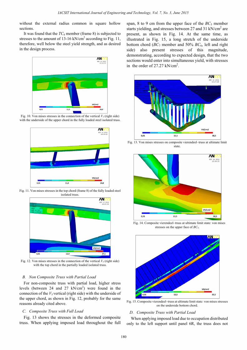
C. Composite Truss with Full Load Fig. 13 shows the stresses in the deformed composite
truss. When applying imposed load throughout the full
span, 8 to 9 cm from the upper face of the BC5 member starts yielding, and stresses between 27 and 31 kN/cm2 are present, as shown in Fig. 14. At the same time, as illustrated in Fig. 15, a long stretch of the underside bottom chord (BC7 member and 50% BC6, left and right side) also present stresses of this magnitude, demonstrating, according to expected design, that the two sections would enter into simultaneous yield, with stresses in the order of 27.27 kN/cm2.
Fig. 13. Von mises stresses on composite vierendeel–truss at ultimate limit
state.
Fig. 14. Composite vierendeel–truss at ultimate limit state: von mises
stresses on the upper face of BC5.
Fig. 15. Composite vierendeel–truss at ultimate limit state: von mises stresses
on the underside bottom chord.
D. Composite Truss with Partial Load When applying imposed load due to occupation distributed
only to the left support until panel 6R, the truss does not
180
IACSIT International Journal of Engineering and Technology, Vol. 7, No. 3, June 2015

deform symmetrically as shown in Fig. 16, and an elevated shear force should be transferred by the 6R Vierendeel panel. This causes a section of about 8 to 9 cm from the upper face of the BC5 member (right side) to begin yielding, showing stresses between 28 and 32 kN/cm2, as shown in Fig. 17, while a long stretch of the underside bottom chord (BC7 and BC6 left) presents stresses between 25 and 28 kN/cm2, as shown in Fig. 18, therefore in the beginning of the yield process.
This behavior was expected in the design process, according to Table IV, since the securities found for members BC7 and BC5 was 0.82<1.0 and 0.95<1.0, respectively, or already it was expected that the upper face of BC5 (right) started yielding before the lower face of BC7.
Fig. 16. Von mises stresses on partially loaded composite vierendeel–truss.
Fig. 17. Partially loaded composite vierendeel-truss: von mises stresses on
the upper face of BC5 (right side).
Fig. 18. Partially loaded composite vierendeel-truss: von mises stresses on
underside of bottom chord.
VI. RESULTS OBTAINED BY NUMERIC ANALYSIS FOR THE SERVICEABILITY LIMIT STATE
The values of the maximum vertical displacements obtained via software Ansys fornon-composite (2.31 cm) and composite (1.99 cm) trusses are illustrated in Fig. 19 and 20, respectively.
Fig. 19. Maximum vertical displacement on the isolated steel truss according
to ansys software.
Fig. 20. Maximum vertical displacement on the composite truss according to
ansys SOFTWARE.
VII. CONCLUSION The results found demonstrate that to make it possible to
construct a composite Vierendeel-truss using welded hollow sections and Vierendeel panels across the whole central third of the span, the project shall keep the horizontal longitudinal shear in the stud bolts, and the resistances of the slab, steel members, joints, and welds within safe limits, making the ultimate limit state be effected by the yield of the bottom chord, through the combination of tension and bending moment.
The analysis of von Mises stresses performed through Ansys modeling showed that the top chord of the steel structure does not yield during the construction phase.
In the case of the composite truss, when the loading was complete throughout the full span, the numeric analysis indicated that the ultimate limit state occurs simultaneously in two positions: on the underside of BC7 member and on the upper surface of BC5 members (left and right sides). The modeling also showed that the vertical V1 and diagonal D1, are the more requested members from the web.
181
IACSIT International Journal of Engineering and Technology, Vol. 7, No. 3, June 2015

When the loading was partially distributed the numerical study showed that the upper face of BC5 (right side) begin to yield just before the lower face of BC7 member.
The modeling software Ansys showed that the points with higher stresses were the same as had been encountered the greatest internal forces, therefore it can be said that the theoretical analysis and bi-dimensional elastic modeling have provided the behavior of the non-composite and composite trusses.
The values of elastic vertical displacements for non-composite and composite trusses, predicted by equations presented by SCI, CSA and ABNT were not suitable for use in a truss with multiple Vierendeel panels. The modeling via softwares ftool and Ansys demonstrated that as the number of panels increases, the structure becomes less rigid and the theoretical displacements become distant from the more realistc values.
The next step of the study is to construct and test the composite hollow Vierendeel-truss to confront the theoretical analysis and elastic and plastic modeling results with the values to be found in the laboratory.
REFERENCES [1] Projeto De Estruturas De Aço E De Estruturas Mistas De Aço E
Concreto De edifícios, ABNT NBR 8800-2008. [2] Eurocode 3: Design of Steel Structures – Part 1-8: Design of Joints,
European Committee for Standardization, EN 1993-1-8:2005. [3] A Solução Definitiva Em Lajes, METFORM, 2010. [4] Limit States Design of Steel Structures, Canadian Standards
Association CAN/CSA-S16-01-2001. [5] R. M. Lawson and S. J. Hicks, Design of Composite Beams with Large
Web Openings – SCI-P-355, The Steel Construction Institute: Ascot, UK. 2011.
[6] Ftool – Two-Dimensional Frame Analysis Tool – Educational Version 2.12. Rio De Janeiro: Pontifícia Universidade Católica do Rio de Janeiro. [Online]. Available: http://www.tecgraf.puc-rio.br/ftool
[7] Ansys Version 10.0 - Basic Analysis Procedure, Houston, Ansys Inc., PA, United States, 2005.
[8] A. O. B. Silva, “Treliça tubular mista com múltiplos painéis vierendeel,” Ph.D. dissertation. Faculdade de Engenharia Civil, Arquitetura e Urbanismo, Universidade de Campinas, Campinas, 2013.
[9] S. Neal, R. Johnson, R. M. Lawson, D. L. Mullett, Design of Composite Trusses – SCI-P-083, The Steel Construction Institute: Ascot, UK. 1992
[10] Projeto De Estruturas De Concreto – Procedimento, ABNT NBR 6118-2003.
Augusto O. B. Silva received his PhD in civil engineering from the University of Campinas in 2013. He was an assistant professor at Paulista University (2007-2011), Integrated Metropolitan College of Campinas (2008-2010) and University Center Our Lady of Patronage (2001-2008). He is currently civil engineer of the municipality of Campinas and his works emphasis in composite structures.
Newton O. P. Júnior received his PhD in civil engineering from the University of São Paulo in 1993. He is currently an assistant professor of State University of Campinas, where he was the coordinator of the Laboratory for Structures and Building Materials of the School of Civil Engineering, Architecture and Urbanism (1996-2003). He is also an advisor for the foundation for research support of the State of São Paulo since 2000. His research interests include high strength concrete and
fiber reinforced concrete.
João A. V. Requena received his PhD in civil engineering from the University of São Paulo in 1995. He is currently an associate professor of State University of Campinas, where he was the director (2002-2006) and an associate director (2001-2002) of the School of Civil Engineering, Architecture and Urbanism. He is also a consultant of Vallourec & Mannesmann of Brazil. His research interests include steel and composite structures.
182
IACSIT International Journal of Engineering and Technology, Vol. 7, No. 3, June 2015