numerical modelling of a centrifuged embankment on soft … modelling of a centrifuged... ·...
TRANSCRIPT

Numerical modelling of a centrifuged embankment on soft clay
M. S. S. ALMEIDACOPPE-UFRJ. POSI Gradualion School, F.d.rol Univ.rsity of Rio d. ian.iro, P.O. Box 68506, 21944,
Rio d. ian.iro Ri, Brazil
AND
A. M. BRITTO AND R. H. G. PARRYEngin..ring D.parlmenl, Cambridg. Univ.rsity, Trumpinglon Slr"I, Cambridg., Unil.d Kingdom CB2 IPZ
Received July 12, 19S5Accepted November 27, 19S5
Biot coupled consolidation numerical analyses have been applied to a stage-constructed embankment on soft clay in thecentrifuge. In the test, the sand embankment was constructed during flight on a clay foundation consisting of an overconsolidatedcrust overlying a normally consolidated layer. Measurements were taken of pore pressures, dissipation rates, and displacementsin the foundation clay. Predictions of these were made using a simple Cam-clay model for the clay and the Cambridge CRJSPcomputer program. A linear elastic idealization was used for the embankment. With some exceptions, pore pressures anddissipation rates were very well predicted, as Y/ere maximum values of both horizontal and vertical displacements. However,displacement profiles with depth were not so well predicted. Particular attention is given in the paper to the detennination ofrelevant values of shear modulus G and the difference in behaviour resulting from using constant permeability and permeabilityvarying with void ratio
K'Y words: embankments, soft clay, centrifuge test, numerical analysis, Biot consolidation, Cam-clay model
Des analyses numeriques associees ~ la thoorie de consolidation de Biot ont etO appliquees ~ un remblai sur argile molleconstruit par etapes dans un centrifuge. Le remblai en sable a etO contruit durant I'essai sur une fondation arsileuse com-prenant une croOte surconsolidee rocouvrant une couche normalement consolidee. Des mesures de pressions interstitielles,de vitesses de dissipation et de deplacements dans la fondation argileuse ont etO prises. Des predictions de ces mesures ont etOfaites au moyen d'un simple mod~le "Cam-clay" pour I'argile et du programme d'ordinateur CRISP de Cambridge. Lecomportement du remblai a ete ideali.. selon un modele d'elasticite lineaire. A quelques exception pres, les pressionsinterstitielles et les vitesses de dissipation ont ete Ires bien predites de meme que les valeurs maximales des deplacementshoriwntaux et verticaux. Cependant, les profils de deplacements en fonction de la profondeur n'ont pas etO aussi bien preditsDans cet article, une attention particuli~re est portee ~ la determination des valeurs du module de cisaillement G, et aucomportement different selon qu'une permeabilite constante ou variant avec I'indice des vides est utilises.
Mols clis: remblais, argile molle, essai centrifuge, analyse numerique, consolidation de Biot, mod~le "Cam-clay."[Traduit par la revue]
Can Gc h J 23. t03-114 (J986)
calculations of pore pressures and displacements and measure-ments taken during the centrifuge testing of a stage-constructedembankment on soft clay.
Centrifugal modellingThe advantages of using the centrifuge to achieve self-weight
and stress path similarity have been discussed by Schofield(1980). In essence, if a model N times smaller than theprototype is subject to an acceleration N times the earth'sgravity field, then the density of all materials in the model willbe increased by N and the stresses at a depth z/N will beidentical to the stresses in the prototype at a depth z. If materialswith the same stress-strain behaviour are used in both modeland prototype, strain similarity is also achieved in both modeland prototype.
An additional advantage of a centrifuge test is the shorteningof time-dependent processes. According to the Terzaghi con-solidation theory, the time for dissipation of excess porepressure is proportional to the square of the drainage path. Asthe model dimensions are reduced by N times,4te draina1e pathis also N times shorter. Hence the model time is N timesshorter than the prototype time. This relation has obviousimplications for the centrifuge modelling of stage-constructedembankments on soft clays.
The centrifuge test reported here is part of an extensiveprogramme of testing carried out at Cambridge to study thebehaviour of embankments on soft clays (Davies 1981; Almeida1984; Almeida et al. 1985; Davies and Parry 1985). The model
Introduction
Realistic computations of the variation of displacements andpore pressures with time. in clay foundations under stage-con-stDIcted embankments. require the use of numerical analyseswith reliable constitutive models coupled with consolidation.
The Cam-clay models (Schofield and Wroth 1968; Roscoeand Burland 1968) allow strength and compressibility to be~ted within the elastoplastic strain-hardening theoreticalframework. using a small number of parameters for bothdrained and undrained analyses. Partial drained behaviour canbe also modelled numerically using the Biot three-dimensionalconsolidation theory. as adopted in the CRISP program (Gunnand Britto 1981). Some common criticisms (e.g. Tavenas 1981)to the original Cam-clay models are the following:(a) the assumption of a yield locus centred on the isotropiccompression line whereas anisotropic consolidated clays exhibityield loci approximately centred on the Ko consolidation line(e.g. Parry and Nadarajah 1973);(b) the assumption of isotropic elastic rather than anisotropicelastic behaviour inside the yield locus;(c) the assumption of associated flow rules, which can beacceptable for isotropic soils but do not properly represent thebehaviour of anisotropic natural clays.Despite the above criticisms, the original Cam-clay modelshave been continuously used at Cambridge. The reasons are thatthey retain mathematical simplicity and use a small set ofparameters obtainable from standard laboratory tests.
This paper is concerned with comparisons between numerical
"'_._"- r.__"- . ,--"-, ... r.__".

104
,001-
j1-::1;; ~;~ _I~&~ ~
ooJ
@,~
~
-0
(i)
@
CAN GEOTECH J VOL. 23.198.
silver spheres that allowed pictures to be taken and displace-ments to be subsequently computed, by the technique describedby James (1973).
During stages 2 and 3 of embankment construction largehorizontal and vertical displacements occurred. Measured andcomputed displacements and pore pressures are presentedbelow. Limit equilibrium effective stress stability analysesusing measured pore pressures produced factors of safety in therange 1.0-1.2 during stages 2 and 3 and a factor of safety of0.91 at failure, as described by Almeida et a/. (1985). A fulldescription of the test, techniques, and analyses performed canbe found in Almeida (1984).
Previous work on critical state numerical modelling,., One strong feature of the Cam-clay models is their ability to
@ lIFT/srAGENO model the behaviour of lightly overconsolidated clays under"--"
stress paths corresponding to embankment loading (Wood1982). Indeed, Cam-clay models have been successfully used
J (e.g. Wroth 1977) for the numerical calculations of thebehaviour of embankments on clay foundations. A brief reviewof prior numerical analyses of embankments on soft clays usingcritical state models is presented below.
The finite element program developed by Simpson (1973)employing models of soil behaviour and based on critical statesoil mechanics was applied to the analysis of the Kings Lynntrial embankment. Drained and undrained analyses showedgood agreement for short- and long-term settlements. Com-puted pore pressure showed less agreement with field measure-ments than displacements and poor agreement was obtainedbetween measured and computed movements outside theembankment toe. The results of these analyses were alsopresented by Wroth and Simpson (1972). Thompson (1976)improved Simpson's program and applied it to a class Aprediction of the MIT trial embankment. The calculations weregood in general, but pore pressure computations in particularwere better than those presented by the other predictors (Wroth1977).
From the findings of Simpson, Thompson, and others(notably Naylor 1975), the CRISTINA (CRItical STate Num-erical Algorithm) program was developed. Bassett eta/. (1981)used a version of CRISTINA with a coupled consolidationalgorithm suggested by Small et a/. (1976) to predict thebehaviour of centrifuged constructed embankments. Davies(1981) used CRISP, the version subsequent to CRISTINA, anddescribed in the next section, for the analysis of centrifuged ~embankments. In both cases excess pore pressures generated bythe embankment construction and their rates of dissipation werefairly well predicted, but the settlements during consolidationwere substantially overpredicted, with a much deeper pattern of
computed displacements.Prediction of the behaviour of a trial embankment on Rio de
Janeiro clay was performed by Almeida (1981) using the CRISPprogram. A coupled consolidation analysis of the month-longperiod was performed and good agreement was observed forboth settlements and pore pressures. When results were alsocompared (Almeida and Ortigao 1982) with numerical calcula-tions using an elastic nonlinear model, the superiority of criticalstate numerical calculations that accounted for the soil con-solidation was made evident.
Other critical state finite element programs have beendeveloped elsewhere, such as the Rosalie program used forpredictions of the Cubzac-les-Ponts A and B trial embankments(Truon~ and Ma~nan 1977; Maj(nan et a/. 1982a, b). Early
mode' I'"'" ~
" "'" 1<XxJ 1"", 2IXxJ
""."pe ,..'s,time
FIG. I. Construction history for stage-constructed embankments
sca~ LIFT 5~~~~~50 1OOmm LN'T
~m L 31FT 2
,.""., UFT 1
~i.P1O Is-
1:P9 i
oPS i P:l1.. eP1eP6 ePl1
85
,',' -Ife P~ Pit"","" l~
c. i 75 150 i 85 f 95 i 80 f
FIG. 2. Centrifuge test MA3: geometry and position of the pore
pressure transducers.
test (Almeida 1984) consisted of a l60mm thick soft clayfoundation fonned by a 90 mm overconsolidated clay overlyinga 70 mm nonnally consolidated layer. In order to produce a stiffcrust, Gault clay was used in the top 40 mm of the model. Bothclays were consolidated together from slurry. The in situ stressstate existing before embankment construction is describedbelow.
The centrifuge test was perfonned at 100 g using the
Cambridge geotechnical centrifuge described by Schofield(1980). Embankments were constructed in flight; the stageconstruction loading history that was adopted during thecentrifuge test and that is to be modelled numerically is shown inFig. I. The embankment was constructed in stages from lift I tolift 3 and was then taken quickly to failure. This occurred 10safter lift 5 was poured, at an average height of 116 mm.
The geometry of the problem is seen in Fig. 2. Since the wallsof the centrifuge container are ideally smooth, the cross sectionof the model represents half of the prototype modelled, as theright-hand-side wall is a plane of symmetry. The positions of the10 miniature pore pressure transducers used are also seen in Fig.2. As the pore pressure transducers were provided with siliconchips, they offer very fast response times, of the order of 0.1 s.The visible section of thl: model was provided with a /(rid of


106 CAN GEOmCH I VOL 23. 1986
Triaxial tests in kaolin carried out bv Houlsby (1981) resulted (j (MPal
0 2 I,0, \ . \. : I . (ja~lt c:ay
-t--ka.lin
50
e!.~15-~ 100
"v v150l \ "
FIG. S. Variation of shear modulus with depth.
300. ~I Cu
.,;
20n
G1 "-"';7~~~,:--' . "- . .
Cu"-Davidson (1980). . '"
~
100~~
Cu,/
°t- -L-2
OCR
FIG. 6. Variation of Gjc. with OCR.
in the laboratory and continuous swelling as it is unloaded andthen subjected to 100 g of acceleration, eventually reachingequilibrium. On the other hand, a soil element at the botton! ofthe clay (see Fig. 8b, element B) experiences loading followedby unloading and subsequent reloading to a normally consoli-dated condition as it reaches equilibrium at N = 100 g.
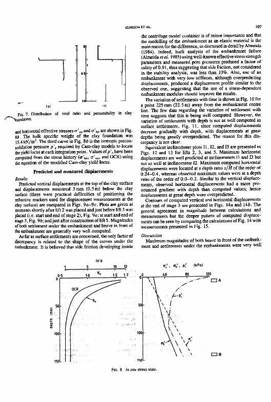
Values of in situ horizontal effective stresses (J'ho werecomputed using values of coefficients of earth pressure at restKo = (J'ho/(J'.o given by the following empirical relationship
found to be suited to Cambridge reconstituted clays:
[5] Ko = Koc'(OCR)+'(radians)
where OCR = (J'.m/(J'.o is the overconsolidation ratio and Kncis the coefficient of earth pressure at rest at the normallyconsolidated condition, equal to 0.69 for both kaolin and Gaultclay (Airey 1984; Thompson 1962). Results from [5] agree wellwith the available experimental data.
Variations of OCR and Ko (given by [5J) with depth in theclay foundation are given in Fig. 8a. Values of in situ venical
[3] G=75'p'
Houlsby also showed that using [3] provided a much better fit tohis triaxial tests than using a constant value of shear modulus.Thus' for the analysis perfonned here the shear modulus forkaolin is constantly updated using [3], despite this equationimplying an unrealistic value of zero for Poisson's ratio when[I] and [3] are substituted in [2a] with e = 1.5 and K = 0.05. For
the Gault clay, G was assumed to be 2250 kPa (see Fig. 5)throughout the analysis. Values of G corresponding to the insitu stress state, p = (2a'", + a'..)/3, are shown in Fig. 5.
Values of G computed by [2a] (making the nonnal assump-tion of v' = 0.3) are also shown in Fig. 5, and are much lower
than those given by [3]. The ratio G/cu, which is a good guidefor the estimated values of G, varies between 130 and 230(Houlsby 1981), as shown in Fig. 6. However, the same ratiogiven by values of G computed by [2a] varies between 27 and74, Fig. 6, whereas that using values of G computed by [3]varies between 72 and 270, Fig. 6. Thus values of G for kaolingiven by [3] seem to be quite realistic, whereas use of [2] mightlead to excessively low values of G, which might explain whysome previous critical state numerical analyses overpredicted
displacements.
Coefficients of permeabilityFor coupled consolidation analysis the program also requires
values of the coefficients of penneability in the horizontal (kh)and vertical (kJdirections.lnthe standard version of CRISP thecoefficient of penneability is assumed to remain constantthroughout the analysis.
However, the penneability is not a soil constant and insituations in which large loads are applied and significantconsolidation takes place, changes in void ratio can lead toimportant changes in the coefficient of penneability. This pointmight be important in stage-constructed embankments and isinvestigated here; two cases have been analysed:
(a) Case A-The penneability was assumed to be dependenton the void ratio; this case was used for direct comparison withthe observed behaviour. Four values of the initial coefficient ofpenneability in the vertical direction (kyo) were used. Fig. 7b,according to the initial void ratio eo, Fig. 7a. The equationadopted to correlate the coefficient of penneability with the voidratio in case A and which was implemented in the originalversion of the CRISP program is the linear relationship betweenlog ky and e given by
[4] ky = kyo'lo<e-eo)/Ck
where k.. and eo have been defined above and C. is the slope ofthe log k, - e plot. The value of C. adopted for both kaolin and
Gault clay was 0.60, which, like kyo, was based on dataavailable at Cambridge (Thompson 1962);
(b) Case C- The penneability was assumed to remainconstant throughout the analysis; this case was used just forcomparison with case A. Only two values of penneability wereused (Fig. 7b): ky = 9.37 X 10-lom/sfortheGaultclayand kv= 2.0 x 10⁻⁹ m/s for the entire kaolin clay layer
In both cases values of kh were assumed to be 1.5 times higherthan those of ky, according to experimental data available at
Cambridge (Chan 1975).
In situ stress stateA soil element close to the clay surface (see Fig 8b, element
A), in clay models used for centrifuge tests, experiences loading
".1;aI,.;d r"~. to
~ ';4 ';!
;,;,., ""ka' ,.."..., of"""""" '" (../.,
,~ " ." ,... - ~I ",' I, -_:.~. co.. c I", - co.. I
J~~ IkaAlI-CIO' 3 I
III
L
ALMEIDA Er AL 107
the centrifuge model container is of minor importance and thatthe modelling of the embankment as an elastic material is themain reason for the difference, as discussed in detail by Almeida(1984). Indeed, back analysis of the embankment failure(Almeida eta/. 1985) using well-known effective stress strengthparameters and measured pore pressures produced a factor ofsafety of 0.91, thus suggesting that side friction, not consideredin the stability analysis, was less than 10%. Also, use of anembankment with very low stiffness, although overpredictingdisplacements, produced a displacement profile similar to theobserved one, suggesting that the use of a stress-dependentembankment modulus should improve the results.
~ The variation of settlements with time is shown in Fig. 10 for101 Ibl a point 225 mm (22.5 m) away from the embankment centre
7 O. tn.b t. fd t. d eab.l .tn cia line. The few data regarding the variation of settlement withfiG IS U Ion 0 VOl ra 10 an penn II y I Y . .. ., d.t . time suggests that thIS IS being well computed. However, the
, "oun a Ion. .. f I .thd th . II tedvarIatIon 0 sell ements WI ep IS not as we compu as
surface settlements, Fig. I I, since computed displacementsdecrease gradually with depth, with displacements at greatdepths being greatly overpredicted. The reason for this dis-crepancy is not clear .
Equivalent inclinometer plots II, 12, and 13 are presented inFigs. 12 and 13 for lifts 2, 3, and 5. Maximum horizontaldisplacements are well predicted at inclinometers II and 13 butnot so well at inclinometer 12. Maximum computed horizontaldisplacements were located at a depth ratio z/H of the order of0.24-0.4, whereas observed maximum values were at a depthratio of the order of 0.0-0.2. Similar to the vertical displace-ments, observed horizontal displacements had a more pro-nounced gradient with depth than computed values; hencedisplacements at great depth were overpredicted.
Contours of computed vertical and horizontal displacementsat the end of stage 3 are presented in Figs. 14a and 14b. Thegeneral agreement in magnitude between calculations andmeasurements but the deeper pattern of computed displace-mentscan be seen by comparing the calculations of Fig. 14 withmeasurements presented in Fig. 15.
DiscussionMaximum magnitudes of both heave in front of the embank-
ment and settlements under the embankments were very well~
and horizontal effective stresses cr'vo and cr'ho are shown in Fig.8b. The bulk specific weight of the clay foundation wasIs.4kN/m3. The third curve in Fig. 8b is the isotropic precon-solidation pressure P'. required by Cam-clay models to locatethe yield locus at each integration point. Values ofp'. have beencomputed from the stress history (cr'ho' cr'voo and OCR) usingthe equation of the modified Cam-clay yield locus.
Predicted and measured displacements
ResultsPredicted vertical displacements at the top of the clay surface
and displacements measured 5 mrn (0.5 m) below the claysurface (there were practical difficulties of positioning thereflective markers used for displacement measurements at theclay surface) are compared in Figs. 9a-9c. Plots are given atmoments shortly after lift 2 was placed and just before lift 3 wasplaced (i.e. start and end of stage 2), Fig. 9a; at start and end ofstage 3, Fig. 9b; and just after construction of lift 5. Magnitudesof both settlement under the embankment and heave in front ofthe embankment are generally very well computed.
As far as surface settlements are concerned, the only factor ofdiscrepancy is related to the shape of the curves under theembankment. It is believed that side friction developing inside
OCR
E!~~~
~

108"me model Im;ol
'I
c.,"" "', ""_..
:
~ 2~O
.. 5
-1051EE
~. 10
~ "OJr.."=
15"51
,.,""'P--ot,"",-,
,- m.",.nO - 5mm 105ml,.'ow "., .,,",.,.
~mb.nkm.nt
~~
FIG. 10. Computed and measured settlements with time
5 I-'~
& Iml
--R.L n8
-;;o~ 1.2 16
:::-=7
/
..a,,'"- .amp,'"/
,.V(a' tift 3-5Ia,' (bl tifl 5-
FIG. II. Computed and measured settlements with depth
lateral deformations of foundations were discussed by Poulos(1972). Predicted horizontal displacements are usually largerthan measurements and Poulos listed the possible reasons for thediscrepancies: (I) the difficulty of estimating Poisson's ratio ofthe soil; (2) anisotropy of the soil; (3) nonlinear stress-strainbehaviour of soil; (4) nonhomogeneity of soil; (5) neglect ofcertain factors such as the effect of embankment stiffness andfoundation roughness or more generally, incorrect assumptionsmade regarding the stresses applied to the soil by the foundationor embankment. Poulos (1972) also pointed out that thesensitivity of the horizontal movements to the factors listedabove is considerably greater than that of vertical displace-ments. It appears that factors (2) and (5) are the most relevant
for the case analysed here.Factor (2), regarding soil anisotropy, is possibly the main
drawback of simple Cam-clay models. Indeed, anisotropicelastic behaviour might be particularly important for the initiallyoverconsolidated top clay layer (see Parry and Wroth 1977).Also, anisotropy in the shape of the yield locus for one-dimensional consolidated soil might be relevant for pointsyielding beyond the toe due to the passive nature of the stress
paths.Related to the influence of anisotropy is the problem of rota-
tion of the direction of principal stresses beyond the embank-ment toe In Cam-clay isotropic models the rotation of principalstresses does not cause additional plastic strains, which is quitecontrary to the experimental evidence. Therefore Cam-claymodels in these circumstances will be too stiff and willunderpredict deformations. This is the case for lateral deforma-tions of points close to the surface in equivalent inclinometers II

6. 1m)6. 1m)ID 05 0-cf ° . , V' / , 11
, .., ,
, ,
~(01 Il-lift 2
~1.0
~
OIIHORIZONTAL OISPLACEMENTS Oh Imml
FIG. 14. Computed vertica! and horizontal displacements
and 12. However, the opposite occurs in the bottom clay layer,which is yielding more than expected, i.e. plastic strains anddisplacements are being overpredicted there.
The modelling of the embankment also seemed to beunsatisfactory, as suggested in (5) above, as a linear elasticmodel does not model the variation of the embankment stiffnesswith stress level. Therefore it is apparent that a more correctmodelling of the embankment material should improve theshape of the settlement curves under the embankment and theprofiles of lateral deformations and settlement with depth.
The discussion by Poulos (1972) was made in the context of a~ quickly built embankment. In the case of a stage-constructed
embankment, the hypotheses regarding the consolidation of th!:-clay foundation might also be important. It was observed in theanalyses performed here that the assumption of permeabilitybeing constant throughout the analysis (case C) has the effect ofincreasing lateral deformations and settlements as compared tothe assumption of permeability varying with void ratio (case A).
Predicted and measured pore pressuresExcess pore pressures Ilu measured during test MA3 are
compared in this section with values of Ilu computed atthe integration point nearest to the respective pore pressuretransducer.
Measured and computed variations of excess pore pressurewith time are presented in Figs. 16 and 17 for 8 of the 10transducers monitored. The agreement is generally good forboth generation and dissipation of pore pressures. Computedpore pressures had a trend of peaking at the end of loadingwhereas measured pore pressures showed some peak delay, i.e
peaked after the end of loading. That is the case of transducerP6, Fig 16c, where, despite the poor agreement, both com-puted and measured pore pressures peaked on completion ofloading lifts 1-3
At transducer P9, Fig. l7b, computed pore pressuresshowed a continuous rise on completion of loading lift I,

~~;=::::~:: IL~
:: I

111
/""-
'",. P6,.."
~"'" .0:"'" .'"'" . " ,. ." - '"~~I" ~ ""'~- ~ ~
'" I.~ P9::J ,. ju .x ;'" .~
...;
~ ~ ~-:-:~~
-~.[ -~, :--:-: l- ...
. .. . ..
~
P2
CQSO A
~~:~~-~~-;.;
~
,..
"... -'
.-'
..-'
: ..~
::-' ~ .. ,---~' ,CQ:'(~--:r-+-. . ,. ,. - ... .."'~...0..
....,.,
"',."X"' .
,
P3
-_r~""""':'":o=":':- --~-==-:~~r"""
",,' .'~.,',- ". '" ,so ." ,- ",TIME Imm! TIME (min)
FIG. 18. Influence of the hypothesis related to the penneability on the pore pressure response.
points at the overconsolidated state and inclined to the left forpoints at the normally consolidated state, which is consistentwith the negligible drainage taking place during the short time ofconstruction. These stress paths generally moved towards the
critical state line with increasing q*(b) During consolidation, a predominantly horizontal line withincreasing p', thus moving away from the critical state lineSlight departures from these typical patterns are seen in theinitially more overconsolidated points PI and PIO, asconsolida-
critical state line (csl) and the modified CaIn-clay yield locus are
also plotted in the p'-q* diagram.Points PI, PIO, and PII are located in the top overconsoli-
dated clay layer, thus stress paths at these points start inside theyield locus. Conversely, points P2, P7, and P8 are in the bottomnormally consolidated layer and their stress paths initiate on theyield locus. Stress paths shown in Fig. 20 may be described as
follows:(a) During loading, undrained type of stress path, vertical for

tion during stage I at PI was associated with increase in q*and only marginal increase in p', and at PIO was associated witha slight decrease in q* while p' was held constant.
Computed stress paths indicate that all three points, PI, PIO,and PII, initially at the overconsolidated state reach yieldingconditions during stage 2 of construction; point PII, the leastoverconsolidated of the three, started yielding in lift I, but PIand PIO, both at Initial Ko conditions very close to unity,reached yield conditions in lift 2. Most of the clay foundationunder the embankment was also at a nonnally consolidated stateat the end of stage 2, which explains why both computed andmeasured defonnations increased more rapidly following com-pletion of lift 3 loading.
At points PS, PIO, and PII under the embankment slope,stre~s paths moved very close to the critical state line,particularly on completion of stages 3 and 5 loading. At pointsP2 and P7 , located at greater depths, stress paths during loading
were predominantly vertical and never approached the critiCalstate line.
ConclusionsA coupled consolidation numerical analysis of a stage-
constructed embankment test has been presented adopting themodified Cam-clay model for the clay foundation. Soft clayparameters were obtained from the large amount of test dataavailable. No calibration of parameters was carried out. Valuesof shear modulus G were made dependent on the mean effectivestress p' and values of penneability were related to the voidratio, as these more realistic assumptions appear to be importantin the case of a stage-constructed embankment.
Good overall agreement of maximum magnitudes of horizon-tal and vertical displacements and of pore pressure variationwith time has been obtained. Agreement was particularlypromising for settlements at the ground surface under th~embankment and for pore pressure generation and dissipationthe kaolin clay.
Agreement was less satisfactory for displacements at greaterdepths, where both horizontal and vertical displacements wereoverpredicted. Shapes of computed and measured lateraldefonnation profiles with depth were also different. Somereasons for the differences are the modelling of the embank-ment as a linear elastic material and that anisotropy of theclay foundation was not considered in the modified Cam-clay model.
Because of the general good agre.ement obtained in thiswell-controlled centrifuge experiment, and indeed with otherfield cases reported in the literature, the numerical modeladopted here is recommended for practical applications ofembankments on soft clays.

AcknowledgementsThe research reported here has been partly funded by a
contract with the Corps of Engineers, U.S. Army, EuropeanResearch Office. Financial support to the first author wasprovided by the Brazilian Research Council (CNPq) and FederalUniversity of Rio de Janeiro (UFRJ). Thanks are also due thetechnical staff of the Soils Group at the Engineering Depart-ment, Cambridge University, for support provided during the
centrifuge tests.
AlREV, D. 1984. Clays in circular simple shear apparatus. Ph.D.thesis, Engineering Department, Cambridge University, Cam-
bridge, England.ALMEIDA, M. S. S 1981. Analysis of the behaviour of an embankment
on soft clay. M.Phil thesis, Engineering Department, Cambridgef""' University, Cambridge, England.
- 1984. Stage constructed embankments on soft clays. Ph.D.thesis, Engineering Department, Cambridge University, Cam-
bridge, England.ALMEIDA, M. S. S., and ORTIGAO, J. A. R. 1982. Performance and
finite element analysis of a trial embankment on soft elay. Proceed-ings of the International Symposium on Numerical Models inGeomechanies, Zurieh, Switzerland, pp. 548-558.
ALMEIDA, M. S. S., and PARRV, R. H. G. 1985. Centrifuge studies ofembankment foundations strengthened with granular coluffiDs. ThirdNTIInternational Geotechnical Seminar, Singapore, pp. 153-163.
ALMEIDA, M. S. S., DAVIES, M. C. R., and PARRV, R. H. G. 1985.Centrifuged embankments on strengthened and unstrengthened clayfoundations. Geotechnique, 35(4), pp. 425-441.
BASSETT, R. H., DAVIES, M. C. R., GUNN, M. J., and PARRY.R. H. G. 1981. Centrifugal models to evaluate numerical methodsProceedings, International Conference on Soil Mechanics and Foun-d.tion Engineering, Stockholm, Sweden, Vol. I, pp. 557-562.
CHAN, K. C. 1975. Stresses and strains induced in soft clay by a stripfooting. Ph.D. thesis, Engineering Department, Cambridge Univer-
sity, Cambridge, England.DAVIDSON, C. S. 1980. The shear modulus of elays, Part II. Research
project, Cambridge University, Cambridge, England.DAVIES, M. C. R. 1981. Centrifugal modelling\of embankments on
clay foundations. Ph.D. thesis, Engineering DepartmenI, Cam-
bridge University, Cambridge, England.DAVIES, M. C. R., and PARRY, R. H. G. 1985. Centrifuge modelling of
embankments on clay foundations. Soils and Foundations. 25, pp19-36.
GIBSON, R. E., KNIGHT, K., and TAYLOR, P. W. 1963. A criticalexperience to examine theories of three dimensional consolidationProceedings, European Conference on Soil Mechanics and Founda-tion Engineering, Weisbaden, West Germany, Vol. I, pp. 69-76
~UNN, M. J., and BRITTO, A. M. 1981. CRlSP-User's andprogranuner's manual. Engineering Department, Cambridge Uni-
versity, Cambridge, England.HOULSBY, G T 1981. A study of plasticity theories and their
applieability to soils. Ph.D. thesis, Engineering Department, Cam-
bridge University, Cambridge, England.JAMES, R. G. 1973. Determination of strains in soils by radiography
CUED/C SOILS LNI(a), Engineering Department, CambridgeUniversity, Cambridge, England
KAVAZANJIAN, E., and POEPSEL, P. H. 1984. Numerical analysis oftwo embankmenI foundations. Proceedings, ASCE Symposium onSedimentation Consolidation Models, San Francisco, CA, pp84-106
MAGNAN, J. P, HUMBERT, P, BELKEZIZ, A, and MOURATIDIS, A1982a. Finite element analysis of eonsolidation, with specialreferenee to the case of strain hardening elastoplastic stress-strainmodels Proceedings, IV International Conference on Numerica!Methods in Geomechanics. Edmonton, Alta, pp 327-336
MAGNAN, J P., HUMBERT, P, and MOURATIDIS, A 1982b Finiteelement analysis of soil deformations with time under an experimen-tal embankment at failure Proceedings, International Conference on
. ET AL 113
Numerical Models in Geomechanics, Zurich, Switzerland, pp.601-609.
NAYLOR, D. J. 1975. Non-linear finite elements for soils. Ph.D. thesisDepartment of Civil Engineering, University College of Swansea,Swansea, United Kingdom.
PARRY, R. H. G., and NADARAJAH, V. 1973. Observations inlaboratory prepared lightly overconsolidated kaolin. Geotechnique,24, pp. 345-357.
PARRY, R. H. G., and WROTH, C. P. 1977. Shear properties of softclays. Report presented at Symposium on Soft Clay, Bangkok,Thailand.
PoULOS, H. G. 1972. Difficulties in prediction of horizontal deforma-tions of foundations. ASCE Journal of the Soil Mechanics andFoundations Division, 98(SM8), pp. 843-848.
ROSCOE, K. H., and BURLAND, J. B. 1968. On the generalizedbehaviour of 'wet' clay. In Engineering plasticity. Edited by JHeyman, and F. Leckie. Cambridge University Press, London,England, pp. 535-609.
SCHOFIELD, A. N. 1980. Cambridge geotechnical centrifuge opera-tions. Geotechnique, 30(3), pp. 227-268.
SCHOFIELD, A. N., and WROTH, C. P. 1968. Critical state soilmechanics. McGraw-Hill, London, England
SIMPSON, B. 1973. Firute element computations in soil mechanics.Ph.D. thesis. Engineering Department, Cambridge University,Cambridge, England.
SMALL, J. C., BOOKER, J. R., and DAVIS, E. H. 1976. Elastoplasticconsolidation of soil. International Journal of Solids and Structures,12(6), pp. 431-488.
TAVENAS, F. 1981. Some aspects of clay behaviour and their conse-quences on modelling techniques. American Society for Testing andMaterials, Special Technical Publication No. 740, pp. 667-677.
THOMPSON, S. A. 1976. Application of finite elements to plane straindeformation and consolidation of soils. Ph.D. thesis EngineeringDepartment, Cambridge University, Cambridge, England.
THOMPSON, W. J. 1962. Some deformation characteristics of Cam-bridge Gault clay. Ph.D. thesis. Engineering Department, Cam-
bridge University, Cambridge, England.TRUONG, D. M., and MAGNAN, J. P. 1977. Application des modeles
tlastoplastiques de l'Universire de Cambridge au calcul du com-portement d'un remblais experimental sur sols mous. LaboratoireCentral des Ponts et Chausstos, Rapport de Recherche LPC No. 74
WOOD, D. M. 1982. Choice of models for geotechnical predictions.Technical Report CUED/D-SOILS TR126. Engineering Depart-ment, Cambridge University, Cambridge, England.
WROTH, C. P. 1977. The predicted performance of soft clay under atrial embankment loading based on the Cam-clay model. In Finiteelements in geornechanics. Edited by G. Gudehus. John Wiley &Sons, Chapt. 6, pp. 191-208.
WROTH, C. P., and SIMPSON, B. 1972. An induced failure of a trialembankment: part II finite element computations. Proceedings,Conference on the Performance of Earth and Earth SupportedStructures, American Society of Civil Engineers, pp 65-79
List of symbolsec, void ratio at critical state line at p' = I kPa
kb, ky permeability in the horizontal and vertical direc-
tionsp' mean normal effective stress = (cr', + cr', +
cr',)/3p'c isotropic preconsolidation pressurep'o mean in situ effective stress = (cr'YO + 2cr'bo)/3q* generalized deviator stress = [(cr', - cr',>' +
(cr', - cr',>, + (cr', - cr',)']'!'
t timeu pore-water pressurez depthCc gradient of the compression line in the e - log
p' plot

c,
C.EGHK'KoKoc
N
CAN GEOfECH J VOL 23. 1986
gradient of the swelling line in the e - log OCR overconsolidation ratio (a'vmla'vO>p' plot K gradient of the swelling line in the e - lnp'slope of the e -log kv line plotYoung's modulus A gradient of the compression line in the e -lop'shear modulus plottotal depth of the clay foundation v' Poisson's ratio in terms of effective stressbulk modulus in terms of effective stress a' " a" a' 3 principal effective stressescoefficient of lateral earth pressure at rest a'h' a'v horizontal and vertical effective stessescoefficient of lateral earth pressure at rest in the a'bo' a'vo in situ horizontal and vertical effective stressesnormally consolidated condition a'vm maximum vertical effective stressgravity scaling factor (centrifuge acceleration.1u excess pore pressureNg) M critical state frictional constant
,,