numiaip 1 mw downstream target window analysis
TRANSCRIPT

NuMI AIP 1 MW Downstream Target Window Analysis
K. AmmiganTSD Topical Meeting05.20.21

Downstream Target Containment Window
• Target DS window assembly: F10085269• 2-step EB-welding
• Beryllium PF-60 disk to Aluminum ring• Beryllium disk and Al ring weldment to
Aluminum flange
NOvA target assembly (700 kW)

Downstream Target Window Analysis for 1 MW AIP upgrade (2019)
• MARS/FEA simulations suggested additional cooling was necessary to reduce beam-induced stresses in the beryllium window
• Aluminum flange modified to include water cooling loop and clamps around the Be window
• 0.5 GPM at 31°C (2550 W/m2.K heat transfer coefficient)• Peak temperature reduced by 10°C • Peak stress reduced by ~40 MPa
• Thermocouple added to monitor flange temperature and infer peak window temperature during operation
• Expected to be around 47 °C at 1 MW (1.5 mm sigma)
Cooling loopThermocouple location
External surfaceInternal surface
Peak σequiv = 182 MPa (center) Peak σequiv = 150 MPa (edge)
~47°C

Thermocouple measurements at 730 kW (σ: 1.3 mm)
• Thermocouple (E:BAFT2) measuring 65 ⸰C at 730 kW (steady-state)• FEA SS model predicts 42 ⸰C (with peak window temperature of 67 ⸰C at 730 kW)
Temperature vs. beam power
2020 2021

Updated MARS and FEA simulations (2021)• Flange/window geometry now include cooling tube, clamps and thermocouple
Updated MARS model (I. Rakhno)
Updated FEA model
MARS energy deposition data• ED in cooling loop and clamps• Applied scaled ED of side clamp to thermocouple sheath• Scaled ED for 1.3 mm sigma on Be window (K. Yonehara)
Updated ANSYS FEA boundary conditions• Flange edge temperature: 45 °C (was previously 31 °C)• Assume 125 µm air gap between cooling loop and flange
• Thermal conductivity of air at 40 °C: 0.02735 W/m.K• Thermal gap conductance: 218.8 W/m2.K
• Assume 125 µm air gap between thermocouple tip and flange• Thermal gap conductance: 218.8 W/m2.K
• Thermocouple end temperature: 40 °C• External surface convection: 3.5 W/m2.K, Tamb: 40 °C• Internal surface convection: 9.4 W/m2.K, Tamb: 100 °C• Cooling loop convection: 2550 W/m2.K, Tamb: 31 °C
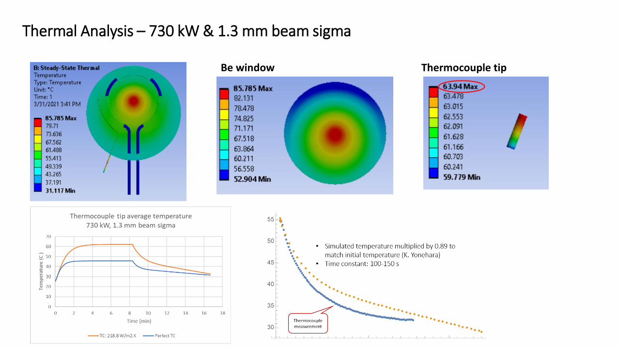
Thermal Analysis – 730 kW & 1.3 mm beam sigma
Be window Thermocouple tip

Operation at 850 kW with 1.3 mm beam sigma
Steady-state temperature Steady-state + Pulse temperature
Boundary condition reaction probe (W)
Flange edge External conv. Internal conv. Cooling loop Thermocouple end
-732 -4.8 16.9 -113.2 -9.1E-2
Thermocouple tip temperature

Operation at 850 kW with 1.3 mm beam sigma
Be window equivalent stress (SS + Pulse)
• Flange edge fixed• Lower internal pressure of 3.5 psig
Maximum principal stress
Minimum principal stress
Peak σequiv = 217 MPa (center) Peak σequiv = 157 MPa (edge)
Peak stresses in compression
Internal surface External surface
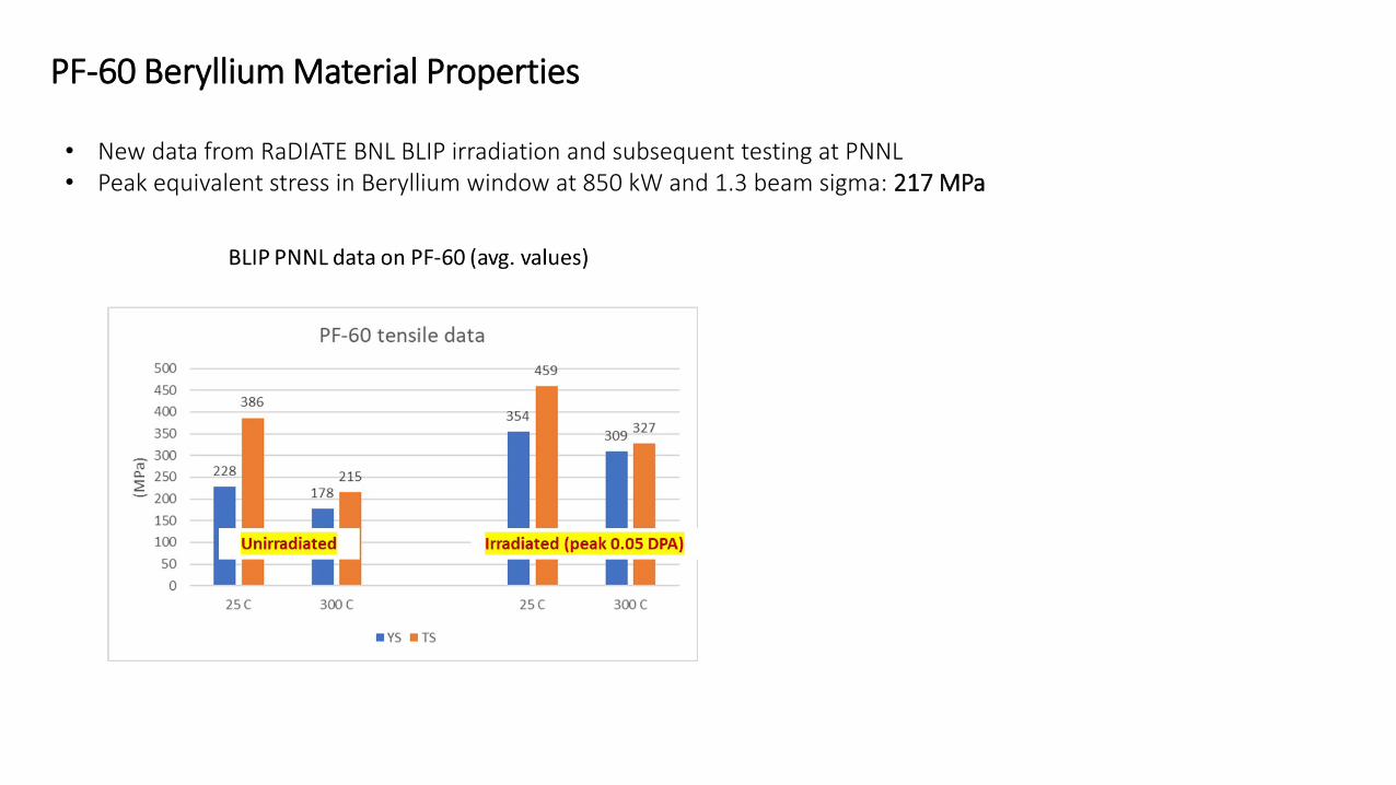
PF-60 Beryllium Material Properties
• New data from RaDIATE BNL BLIP irradiation and subsequent testing at PNNL• Peak equivalent stress in Beryllium window at 850 kW and 1.3 beam sigma: 217 MPa

More recent thermocouple measurements
• Beam shower effects on thermocouple?• Thermocouple degradation due to radiation damage?• Poor thermal contact between thermocouple tip and
flange?• Plugged cooling loop orifice?
• Thermocouple readings somewhat questionable• ~75 °C at 750 kW (05.20.21)• ~73 °C at 820 kW (05.13.21)• ~64 °C at 620 kW (04.30.21)• ~60-65 °C at 730 kW (2020)
Next DS target window assembly…• Improve thermal contact for cooling loop and
thermocouple (indium foil)• Additional instrumentation to monitor window?• Additional cooling?• Thermocouple inspection/calibration?