o working temperature applicable medium
TRANSCRIPT

● Specification
Specification JIS - 5K Flange
Working Pressure 5 Kgf/cm2
Leakage Test(Hyd.oil, 5 min.)
Seat : 7 Kgf/cm2
Body : 8 Kgf/cm2
Working Temperature -20 OC to +150 OC (- 4OF to 302OF)
Applicable Medium Fuel Oil, Lub. Oil, Fresh Water, Steam, Compressed Air.
● Features
www.hsmecorp.com
VALVES
for Shipbuilding & Diesel Engine

www.hsmecorp.com
Indicator Valves
Marine Propulsion and Power Generation Diesel Engine
Indicator Valves measure and monitor the cylinder pressure of diesel engine while the engine is running. This is to analyze the condition and effectiveness of the engine.
Valve is mounted over the each cylinder head of diesel engine. Through a bore the indicator valve is connected to combustion chamber (cylinder). A pressure gauge is connected to indicator port of the valve.
The indicator port is, if required, connected to a measuring instrument in order to read the cylinder ’s condition and effect.
Indicator valve is the major tool in working out horsepower rating. Also useful diagnostic tool to identify problem of injection valve and piston ring leakage. They work on Pmax and Pcom pressure against piston movement, and the resulting trace is marked onto a piece of treated paper for a record.
Diagram shown: Cylinder maximum pressure Pmax
Cylinder compression pressure Pcom
Catalog #: VI-2
May. 2015
- 1 -
www.hsmecorp.com
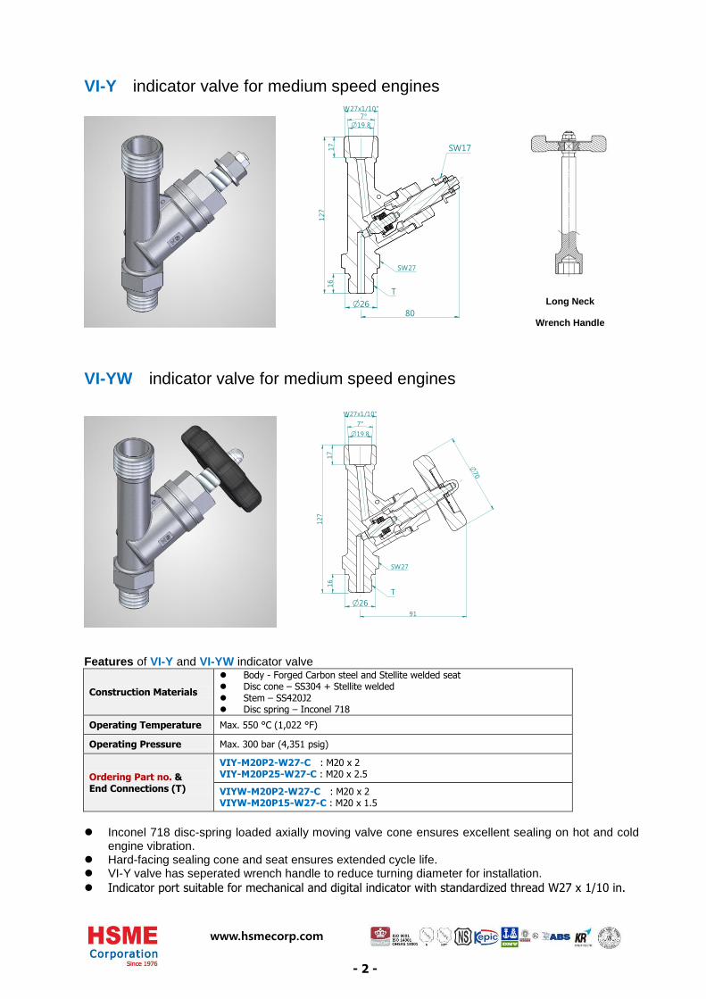
VI-Y indicator valve for medium speed engines
A
A19.8O7°
27W x1/10"
16
17
127
SW27
T
SW17
26O80
VI-YW indicator valve for medium speed engines
26O
19.8O7°
27W x1/10"
16
17
127
70
O
91
SW27
T
Features of VI-Y and VI-YW indicator valve
Construction Materials
Body - Forged Carbon steel and Stellite welded seat Disc cone – SS304 + Stellite welded Stem – SS420J2 Disc spring – Inconel 718
Operating Temperature Max. 550 °C (1,022 °F)
Operating Pressure Max. 300 bar (4,351 psig)
Ordering Part no. & End Connections (T)
VIY-M20P2-W27-C : M20 x 2 VIY-M20P25-W27-C : M20 x 2.5
VIYW-M20P2-W27-C : M20 x 2 VIYW-M20P15-W27-C : M20 x 1.5
Inconel 718 disc-spring loaded axially moving valve cone ensures excellent sealing on hot and cold
engine vibration. Hard-facing sealing cone and seat ensures extended cycle life. VI-Y valve has seperated wrench handle to reduce turning diameter for installation.
Indicator port suitable for mechanical and digital indicator with standardized thread W27 x 1/10 in.
Long Neck
Wrench Handle
- 2 -

www.hsmecorp.com
VI-H indicator valve for medium speed engines
27W x1/10"
19.8O7°O
26.8O
17
110
40.4
16
17
SW
T
VI-L indicator valve for low speed engines
19.8
O 7°
26O41
17
18
43
123
70O
27
Wx1
/10"
T
Features of VI-L indicator valve
Construction Materials
Body - Forged Carbon steel and Stellite welded seat Disc cone – SS304 + Stellite welded Stem – SS420J2 Disc spring – Inconel 718
Operating Temperature Max. 400 °C (752 °F)
Operating Pressure Max. 300 bar (4,351 psig)
Ordering Part no. & End Connections (T)
VIL-W19-W27-C : W3/4” VIL-M20P15-W27-C : M20 x 1.5
Inconel 718 disc-spring loaded axially moving valve cone ensures excellent sealing on hot and cold
engine vibration. Hard-facing sealing cone and seat ensures extended cycle life.
Indicator port suitable for mechanical and digital indicator with standardized thread W27 x 1/10 in.
Features of VI-H indicator valve
Construction Materials Body - Forged Carbon steel Stem – Nimonic 80A
Operating Temperature Max. 550 °C (1,022 °F)
Operating Pressure Max. 300 bar (4,351 psig)
Ordering Part no. & End Connections (T)
VIH-M20P2-W27-C : M20 x 2
Compact type and has minimum rotating radius. Valves are designed with back-seat sealing
- 3 -

www.hsmecorp.com
VI-HB indicator valve for low speed engines
VI-HBW indicator valve for low speed engines
Features of VI-HB and VI-HBW indicator valve
Construction Materials
Body – Ni-Cr-Mo alloy steel + Stainless steel Seat – Nimonic 80A Stem – Nimonic 80A Stem guide – High strength brass Hand wheel – Carbon steel + high performance polyamide resin cover
Operating Temperature Max. 400 °C (752 °F)
Operating Pressure Max. 300 bar (4,351 psig)
Ordering Part no. & End Connections (T)
VIHB-W19-W27-C : W3/4”-10
VIHBW-W19-W27-C : W3/4”-10
Valves are designed with back-seat sealing. Hard-facing sealing cone and seat ensures extended cycle life. Excellent creep-resistant Alloy 80A /ASTM B637 on seat and stem. Valves open and close in all temperature, using either a built-in heat-protected wheel handle or a
separated long wrench handle.
Wrench handle with red vinyl sleeve For Hex Head 19mm actuation.
Unit: mm
Part Number H L W Weight
ST-RW-H19M 19 170 20 180 g
- 4 -

www.hsmecorp.com
VI-HBS indicator valve for low speed engines
VI-HJS indicator valve for low speed engines
Features of VI-HBS and VI-HJS indicator valve
Construction Materials
Body – Stainless steel Seat – Nimonic 80A Stem – Nimonic 80A Stem guide – High strength brass Wrench handle – Tool alloy with vinyl sleeve
Operating Temperature Max. 400 °C (752 °F)
Operating Pressure Max. 300 bar (4,351 psig)
Ordering Part no. & End Connections (T)
VIHBS-FM24P15-W27-S4 : Female M24 x 1.5
VIHJS-M20P15-W27-S4 : M20 x 1.5
Valves are designed with back-seat sealing. Hard-facing sealing cone and seat ensures extended cycle life. Excellent creep-resistant Alloy 80A /ASTM B637 on seat and stem. Valves open and close in all temperature, using either a built-in heat-protected wheel handle or a
separated long wrench handle.
Wrench handle with red vinyl sleeve For Hex Head 24mm actuation.
Unit: mm
Part Number H L W Weight
ST-RW-H24M 24 240 23 380 g
- 5 -

VS Series Safety Valves
7www.hsmecorp.com
Features
Materials of Construction
VS Series Safety Valves have been supplied globally and gained excellent reputation by its superb performance on
marine propulsion and power generation diesel engines since 1976.
• High temperature application: up to 600 °C (1112 °F)
•Working pressure: up to 413 bar (6000 psig)
• Valve provides metal to metal sealing for high temperature application.
• Sealing cone and bush seat are constructed out of excellent creep-resistant exotic alloy.
•When system pressure overcomes the set pressure, the valve opens to relieve the system pressure toatmosphere so as to prevent excess pressure in the system.
• Repeatability of set pressure is not more than 5% above or below of each valve after initial cracking at room temperature.
• VSS Series is provided for extra safety with the deflector cap.
VS Series Safety Valves
Picture Shown:VSS Series Valve
Components
Valve Body MaterialSS304 SS316
VS Series VSS Series VS Series VSS Series
Material Grade /JIS, ASTM Standard1 Lock Nut Black Phosphate coated Steel
S45C-N/JIS G4051SS316/ASTM A276, A479
2 Adjusting Cap3 Spring SWOSC-V/JIS G3561 SS17700 Type 631/ASTM A3134 Stem SCM415/JIS G4053
SS316/ASTM A276, A4795 Stem Guide SS304/A276, A4796 Sealing Cone
Alloy 80A UNS N07080/ASTM B6377 Bush Seat
8 BonnetVS Series: Vented Bonnet
VSS Series: Unvented Bonnet
SS304/A276, A479 SS316/ASTM A276, A4799 Vented Body SS304/A276, A479 SS316/ASTM A276, A479
10 Deflector Cap Black Phosphate coatedSteel S20C/JIS G4051 SS316/ASTM A276, A479
VS Series VSS Series
Technical Information
• Working Pressure: 413 bar (6000 psig)
• Temperature Rating: -60 to 600 °C (-76 to 1112 °F)
1
2
3
4
5
6
7
8
9
10

VS Series Safety Valves
Set Pressure Range
Ordering Information and Dimensions
VS Series VSS Series
Factory TestEvery valve is factory-tested for cracking and resealing performance.
Product Cleaning Valves are cleaned and packaged in accordance with HSME cleaning standard CS-01
Contact Information
For Local Customers
T 051-264-7700 – 4F 051-264-7705E [email protected]
For Overseas Customers
T +82 70 4346 6211 / 6326F +82 70 8282 5112E [email protected]
Corporate Office & Factory 595-1 Hwajeon-dong, Gangseo-gu, BusanSouth Korea 618-280 www.hsmecorp.com
Spring Designator
Set Pressure Rangebar psig
160 160 to 200 2320 to 2900200 200 to 240 2900 to 3480240 240 to 280 3480 to 4060
BasicOrdering Number
End ConnectionsInlet
Orifice, mm (in.)
Dimensions, mm (in.)
Wrench Flat, mm (in.) Net Weight,
gramH D Hex A B
VS-M22P15- M22 x 1.5 Metric
4.0 (0.16)123.20 (4.85)
25.0
(0.98) 27.0
(1 1/16)10.0 (0.39)
22.0 (0.87)
388M8N- 1/2 in. Male NPT
VSS-M22P15- M22 x 1.5 Metric 40.0
(1.57)1040
M8N- 1/2 in. Male NPT
Ordering StepsStep 1. Select basic ordering number. i.e., VS-M8N-Step 2. Insert the spring designator to the basic ordering number. VS-M-M8N-200-Step 3. Select valve body material designator. SS304: S4, SS316: SS i.e., VS-M-M8N-200-S4
• All dimensions in this catalog are reference only and are subject to change.
• Dimensions with M Tube Fitting nuts are finger-tight position.
Safe Valve SelectionThe selection of a valve for any application or system must be considered to ensure safe performance. Valve rating, valve function, material compatibility, proper installation, operation and maintenance remain the sole responsibility of the system designer and the user. HSME Corporation accepts no liability for any improper selection, compatibility, installation, operation or maintenance.
Adjusting CapSet-Pressure Adjustment
Lock NutLockout of Adjusting Cap
Vented BonnetOverpressure venting to Atmosphere
Unvented Bonnet
Deflector CapDeflects flow, prevents contamination from entering valve
Stem GuideKeeps Stem functioning
Stem Tip
Extra-hardened by high frequency process
Loose Sealing ConeHigh temperature alloy construction
Bush Seat
High temperature alloy construction
Dimensions

Air Start ValveAir Start Valve is inserted into each cylinder head of diesel engine and supplies about 30 bar air into
engine cylinder. The air actuates the piston before fuel runs the engine.
The air start valves shown above & below are for Hyundai “Himsen” four-stroke diesel engines.

Air Start Valve
www.hsmecorp.com
Main starting air 30bar from the manifold enters the Valve Air Chamber via the circumferential ports in the valve body. The air pressure in valve chamber will not open the valve because a closing spring holds the valve shut.
To open valve, pilot air from the air start distributor enters the Pilot Air Chamber on the top of the valve and acts on a piston to compress the spring downwards. When the pilot air signal from the air start distributor is vented, the spring closes the valve.
OPERATION
Diagram Shown
Photo Shown:Before pusher is inserted into
cylinder head After pusher is inserted into
cylinder head
Photo Shown:
A set of air start valve and pusher installed in diesel engine

www.hsmecorp.com
VTA Test Valve Block (Diagnostic Valve Block)
VTA Series Test valve block is designed to service with pressure measuring sensor and pressure gauge on
Block mount Bolt & washer
Features
Construction Materials
Valve block – Aluminium A6061BD, colorless anodized Inlet connector – Aluminium A6061BD, colorless anodized Ball valve ball, stem – Stainless steel SS304, SS316L(optional) Ball valve seatring – POM O-ring – FPM(Viton) Test coupling, Bolt & Washer : Carbon steel, electric galvanized
Operating Temperature -20 °C to +120 °C (- 4 °F to 248 °F)
Pressure Operating : -0.8 to 100 bar (3,526 psig) Overload : 150 bar Bursting : 250 bar
Applicable Medium Lube oil, Water, Air
Leakage test Tested with air at 100 bar pressure, leakage < 3.5 mbar/s
Rugged & compact block design Improved vibration resistance Vertical or horizontal mounting
Catalog #: VTA-2
May. 2015
Inlet conector
Ball valve Test coupling
Protection cap
Mount hole Valve block
Photo Shown: Pressure sensors installed on a test valve block for service of a marine propulsion engine.

www.hsmecorp.com
VTA Straight path test valve block
Ordering Part no.
Pitch Flowing dwg. Input & output
No.
Pitch no. N Length, L
Weight Kg.
Connection part
VTA-11-A6 -
1 0 36 0.4
Inlet : PF1/4 Outlet: Flange /
M5x8L Test Coupling: M16x1.5
VTA-22-C40-A6
40
2 1 76 0.8
VTA-33-C40-A6 3 2 116 1.2
VTA-44-C40-A6 4 3 156 1.6
VTA-55-C40-A6 5 4 196 2.0
VTA-22-C38-A6
38
2 1 76 0.8
VTA-33-C38-A6 3 2 114 1.2
VTA-44-C38-A6 4 3 152 1.6
VTA-55-C38-A6 5 4 190 2.0
VTA-12-C40-A6
40
1 - 2 1 76 0.8
VTA-13-C40-A6 1 - 3 2 116 1.2
VTA-14-C40-A6 1 - 4 3 156 1.6
VTA-15-C40-A6 1 - 5 4 196 2.0
Ball valve actuation handle To open or shut-off the ball valve on the valve block, the optional lever handle may be required. Ordering number: 9VLH-S795-C Handle Description 7mm Square actuation 95mm Length Yellow-zinc plated Steel
● Dimension

www.hsmecorp.com
VTA1T Tee path test valve
Ordering Information
Example VTA 11 - C 40 - A6
(1) (2) (3) (4) (5) No. (1) VTA, VTA1T : The designator of Test Valve Block No. (2) Numbers of input & output ports and various flow paths
Custom input and output port combination is available.
No. (3) C: Push-Open check valve in the test coupling P: Plug 1/4 in. PF
No. (4) 38, 40 : The pitch between each path No. (5) Valve Block Material
Ordering Part no. Conn. type T L1 L2 Construction Materials
VTA1T-02GE02G-A6 Test coupling G1/4 67 12 Valve block – Aluminium A6061BD, colorless anodized
VTA1T-04GE02G-A6 M16x1.5 G1/2 69 14 Ball valve, Conn.plug – Stainless steel SS304
VTA1T-02GE03-A6 Flange G1/4 67 12 Test coupling – Carbon steel, electric galvanized
VTA1T-04GE03-A6 M5x8L G1/2 69 14 O-ring,ED-ring – FPM(Viton)
A6 Aluminum alloy A6061BD
CNP Steel nickel plated
BCP Brass C3604BD with chrome plated
Pitch

www.hsmecorp.com
VBCP Compact Ball Valve
● Dimension ● Construction Materials
The end letter of part no. showes body material ; C – Carbon Steel FCD – Ductile cast iron FCD450
S4 – Stainless Steel casting SCS13
● Features
No. Part Name Material Spec.
1 Body FCD 450 SCS 13
2 Cover SS 400 SUS 304
3 Ball SCS 13
4 Stem SUS 304
5 Seat Ring PTFE + Glass
6 O-Ring VITON
7 V-Packing PTFE
8 Locking
Device SUS 304
9 Handle SS 400
Pressure Ordering Part no. ¢ d L E H FLANGE
¢ D ¢ C K N-d2
JIS – 5K
VBCP-5K20A-C 20 38 150 69 85 65 12 4-M10
VBCP-5K25A-FCD 25 42 150 85 95 75 12 4-M10
VBCP-5K32A-FCD 32 50 170 100 115 90 15 4-M12
VBCP-5K40A-FCD 39 60 170 105 120 95 15 4-M12
VBCP-5K50A-FCD 46 70 190 110 130 105 20 4-M12
VBCP-5K65A-FCD 62 95 210 122 155 130 20 4-M12
VBCP-5K80A-FCD 72 110 230 140 180 145 25 4-M16
VBCP-5K100A-FCD 85 132 380 142 200 165 30 4-M16
JIS – 20K
VBCP-20K20A-C 20 38 150 80 100 75 12 4-M12
VBCP-20K25A-FCD 25 42 150 100 125 90 15 4-M16
VBCP-20K32A-FCD 32 50 170 110 135 100 15 4-M16
VBCP-20K40A-FCD 39 60 170 115 140 105 20 4-M16
VBCP-20K50A-FCD 46 70 190 123 155 120 25 8-M16
VBCP-20K65A-FCD 62 95 210 132 175 140 30 8-M16
VBCP-20K80A-FCD 72 110 230 150 200 160 35 8-M20
VBCP-20K100A-FCD 85 130 380 160 225 185 35 8-M20
Specification JIS - 5K Flange JIS – 20K Flange
Working Pressure 5 Kgf/cm2 20 Kgf/cm2
Leakage Test (Hyd.oil, 5 min.)
Seat : 6 Kgf/cm2 Body : 8 Kgf/cm2
Seat : 25 Kgf/cm2 Body : 30 Kgf/cm2
Working Temperature -20 °C to +150 °C (- 4 °F to 302 °F)
Applicable Medium Fuel Oil, Lub. Oil, Fresh Water, Steam, Sea Water, Compressed Air.
Catalog #: VBCP-1
Jun. 2015
Unit: mm

www.hsmecorp.com
VBW Wheel Handle Ball Valve
Example VBW – B – 20 – C
(1) (2) (3) (4)
Ordering
Part no. Ø D T Ø d K L1 L2 SW1 SW2 SW3 H R
VBW-B-10-C 10 - 13 - 65 103 36 30 19 69
70
VBW-B-12-C 12 - 13 - 65 103 36 30 22 69
VBW-B-15-C 15 - 13 - 67 107 36 30 27 69
VBW-B-16-C 16 - 13 - 67 107 36 30 30 69
VBW-B-18-C 18 - 13 - 67 108 36 30 32 69
VBW-B-20-C 20 - 17 - 79 121 41 36 36 72
VBW-B-22-C 22 - 17 - 78 122 41 36 36 72
VBW-B-25-C 25 - 20 - 84 131 46 41 41 76
VBW-B-28-C 28 - 20 - 84 132 46 41 46 76
VBW-B-8A-C 13.8 - 13 - 67 106 36 30 24 69
70
VBW-B-10A-C 17.3 - 13 - 67 108 36 30 32 69
VBW-B-15A-C 21.7 - 17 - 78 122 41 36 36 72
VBW-B-20A-C 27.2 - 20 - 84 132 46 41 46 76
VBW-B-25A-C 34.0 - 20 - 104 139 46 46 55 76
VBW-MB-03R10A-C 17.3 R3/8 13 15 82 95 36 30 32 69
70
VBW-FB-04R10A-C 17.3 R1/2 13 15 82 95 36 30 32 69
VBW-MB-04G10A-C 17.3 G1/2 13 14 67 108 36 30 32 69
VBW-MB-06R25-C 25 R3/4 20 20 93 117 46 41 41 76
VBW-MB-08R25-C 25 R1 20 22 95 117 46 41 41 76
No. Part Name Material Spec.
Steel Brass SS304
1 Body Steel C3771 SS304
2 Connector Steel C3604 SS304
3 O-Ring Steel C3604 SS304
4 Ball SS304
5 Seat Ring PTFE
6 Stem SS304
7 Locking Device Steel, Red painted
8 Wheel handle Nylon glass
9 Name plate C2801P
10 Nut Steel C3604 SS304
11 Sleeve Steel C3604 SS304
Working Pressure 40 Kgf/cm2
Leakage Test (Air, 5 min.) Seat : 45 Kgf/cm2, Body : 60 Kgf/cm2
Working Temperature - 20 °C to + 150 °C (- 4 °F to 302 °F)
Applicable Medium Fuel Oil, Lub. Oil, Fresh Water, Steam, Compressed Air.
Catalog #: VBW-1
Jun. 2015
Unit: mm ● Dimension ● Construction Materials
● Construction Materials
● Ordering Information
Specification JIS - 5K Flange
No. (1) VBW : The designator of ball valve No. (2) B-Bite type, M-Male thread, F-Female thread No. (3) 10~28, 8A~25A : Tube size and Pipe norminal size 03R~08R, G1/2 : Straight pipe thread and Pararrel pipe thread No. (4) Valve body material as shown
C – Carbon Steel, B – Brass, S4 – SS304
● Specification
Specification JIS - 5K Flange
Working Pressure 5 Kgf/cm2
Leakage Test (Hyd.oil, 5 min.)
Seat : 7 Kgf/cm2 Body : 8 Kgf/cm2
Working Temperature -20 OC to +150 OC (- 4OF to 302OF)
Applicable Medium Fuel Oil, Lub. Oil, Fresh Water, Steam, Compressed Air.
● Features
● Features
● This ball valve has wheel handle instead
of lever handle and it prevent
unexpected operating by touch handle.
● Name plate showes flow direction and
system.
● Operating procedure of locking device
1) Lift up and turn 45° locking device
2) Operate handle 90°
3) Turn locking device until push down to holding position
● Ordering Information
Specification JIS - 5K Flange
Working Pressure 5 Kgf/cm2
Leakage Test (Hyd.oil, 5 min.)
Seat : 7 Kgf/cm2 Body : 8 Kgf/cm2
Working Temperature -20 OC to +150 OC (- 4OF to 302OF)
Applicable Medium Fuel Oil, Lub. Oil, Fresh Water, Steam, Compressed Air.
● Features

www.hsmecorp.com
VBWF Swivel flange Ball Valve
● This valve has swivel flanges and it helps fabrication work with easy connection to other flange.
● And could be used instead of many bronze casted valves in ship and ship engine system.
Example VBWF – 5K 15A – C
(1) (2) (3) (4)
Ordering
Part no. Ø d L A E F H
Body
Hex.
FLANGE
Ø D ¢C T N-Ø h
VBWF-5K15A-C 17 100 56 130 44.6 77 41 80 60 10.0 4-Ø 12
VBWF-5K20A-C 20 110 64 130 49.0 80 46 85 65 10.5 4-Ø 12
VBWF-5K25A-C 20 120 64 130 49.0 80 46 95 75 10.5 4-Ø 12
No. Part Name Material Spec.
Steel Brass SS304
1 Body SS400 C3771 SS304
2 Connector SS400 C3604 SS304
3 Flange SS400 C3604 SS304
4 Ball SUS 304
5 Seat Ring PTFE
6 O-Ring VITON
7 Stem SUS 304
8 Locking
Device
SS 400
Red painted
9 Handle SS 400
Specification JIS - 5K Flange
Working Pressure 5 Kgf/cm2
Leakage Test (Hyd.oil, 5 min.)
Seat : 6 Kgf/cm2 Body : 8 Kgf/cm2
Working Temperature -20 °C to +150 °C (- 4 °F to 302 °F)
Applicable Medium Fuel Oil, Lub. Oil, Fresh Water, Steam, Compressed Air.
Catalog #: VBWF-1
Jun. 2015
Unit: mm ● Dimension ● Construction Materials
● Construction Materials
● Features
Specification JIS - 5K Flange
Working Pressure 5 Kgf/cm2
Leakage Test (Hyd.oil, 5 min.)
Seat : 7 Kgf/cm2 Body : 8 Kgf/cm2
Working Temperature -20 OC to +150 OC (- 4OF to 302OF)
Applicable Medium Fuel Oil, Lub. Oil, Fresh Water, Steam, Compressed Air.
● Features
● Ordering Information
Specification JIS - 5K Flange
Working Pressure 5 Kgf/cm2
Leakage Test (Hyd.oil, 5 min.)
Seat : 7 Kgf/cm2 Body : 8 Kgf/cm2
Working Temperature -20 OC to +150 OC (- 4OF to 302OF)
Applicable Medium Fuel Oil, Lub. Oil, Fresh Water, Steam, Compressed Air.
● Features
No. (1) VBWF : The designator of ball valve No. (2) 5K : JIS Flange pressure No. (3) 15A,20A & 25A : JIS Flange size No. (4) Valve body material as shown C – Carbon Steel, yellow zinc galvanized B – Brass C3771 or C3604 S4 – SS304
www.hsmecorp.com
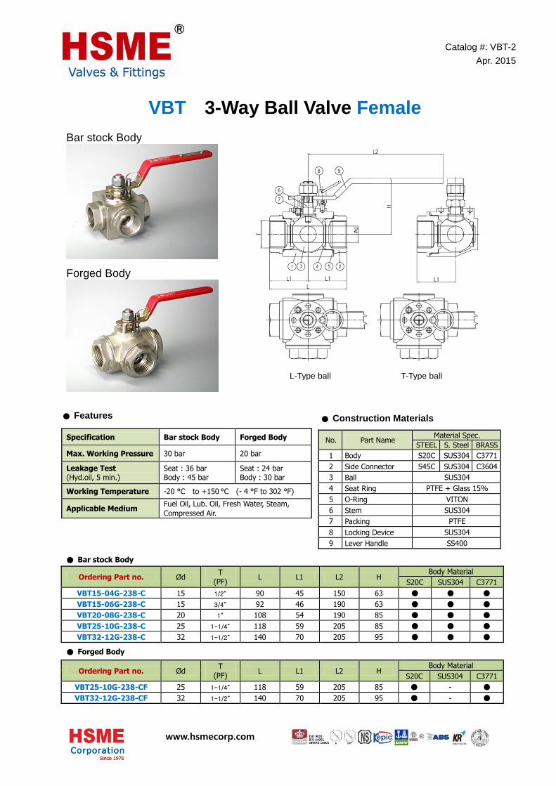
VBT 3-Way Ball Valve Female Bar stock Body
Forged Body
● Bar stock Body
Ordering Part no. Ø d T
(PF) L L1 L2 H
Body Material
S20C SUS304 C3771
VBT15-04G-238-C 15 1/2” 90 45 150 63 ● ● ●
VBT15-06G-238-C 15 3/4” 92 46 190 63 ● ● ●
VBT20-08G-238-C 20 1” 108 54 190 85 ● ● ●
VBT25-10G-238-C 25 1-1/4” 118 59 205 85 ● ● ●
VBT32-12G-238-C 32 1-1/2” 140 70 205 95 ● ● ●
● Forged Body
Ordering Part no. Ø d T
(PF) L L1 L2 H
Body Material
S20C SUS304 C3771
VBT25-10G-238-CF 25 1-1/4” 118 59 205 85 ● - ●
VBT32-12G-238-CF 32 1-1/2” 140 70 205 95 ● - ●
Specification Bar stock Body Forged Body
Max. Working Pressure 30 bar 20 bar
Leakage Test (Hyd.oil, 5 min.)
Seat : 36 bar
Body : 45 bar Seat : 24 bar
Body : 30 bar
Working Temperature -20 °C to +150 °C (- 4 °F to 302 °F)
Applicable Medium Fuel Oil, Lub. Oil, Fresh Water, Steam,
Compressed Air.
Catalog #: VBT-2
Apr. 2015
L-Type ball T-Type ball
● Features
Specification JIS - 5K Flange
Working Pressure 5 Kgf/cm2
Leakage Test (Hyd.oil, 5 min.)
Seat : 7 Kgf/cm2 Body : 8 Kgf/cm2
Working Temperature -20 OC to +150 OC (- 4OF to 302OF)
Applicable Medium Fuel Oil, Lub. Oil, Fresh Water, Steam, Compressed Air.
● Features
● Construction Materials
No. Part Name Material Spec.
STEEL S. Steel BRASS
1 Body S20C SUS304 C3771
2 Side Connector S45C SUS304 C3604
3 Ball SUS304
4 Seat Ring PTFE + Glass 15%
5 O-Ring VITON
6 Stem SUS304
7 Packing PTFE
8 Locking Device SUS304
9 Lever Handle SS400

www.hsmecorp.com
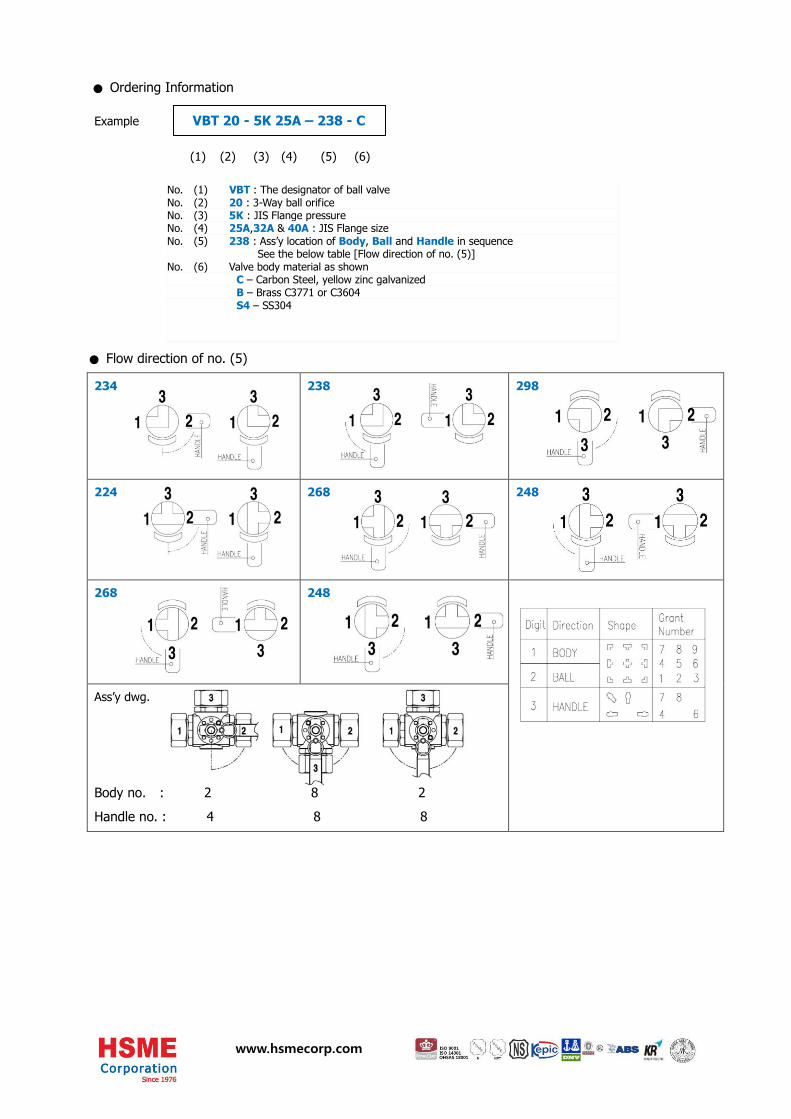
Example VBT 20 – 08G – 238 - C
(1) (2) (3) (4) (5)
234 238 298
224 268 248
268 248
Ass’y dwg.
Body no. : 2 8 2
Handle no. : 4 8 8
● Ordering Information
Specification JIS - 5K Flange
Working Pressure 5 Kgf/cm2
Leakage Test (Hyd.oil, 5 min.)
Seat : 7 Kgf/cm2 Body : 8 Kgf/cm2
Working Temperature -20 OC to +150 OC (- 4OF to 302OF)
Applicable Medium Fuel Oil, Lub. Oil, Fresh Water, Steam, Compressed Air.
● Features
No. (1) VBT : The designator of ball valve No. (2) 20 : 3-Way ball orifice No. (3) 08G : Pipe thread size and thread kind (G: parallel, R: taped)
Symbol 04G 06G 08G 10G 12G
Thread Size 1/2” 3/4” 1” 1-1/4” 1-1/2”
No. (4) 238 : Ass’y location of Body, Ball and Handle in sequence See the below table [Flow direction of no. (4)]
No. (5) Valve body material as shown C – Carbon Steel, yellow zinc galvanized B – Brass C3771 or C3604
S4 – SS304
● Flow direction of no. (4)
Specification JIS - 5K Flange
Working Pressure 5 Kgf/cm2
Leakage Test (Hyd.oil, 5 min.)
Seat : 7 Kgf/cm2 Body : 8 Kgf/cm2
Working Temperature -20 OC to +150 OC (- 4OF to 302OF)
Applicable Medium Fuel Oil, Lub. Oil, Fresh Water, Steam, Compressed Air.
● Features

www.hsmecorp.com
VBT 3-Way Ball Valve
valve has swivel flanges and it helps fabrication work with easy connection to other flange.
● JIS – 5K Flange
Ordering Part no. Ø d H L1 L2 FLANGE
Ø D Ø C Ø G T N-Ø h
VBT20-5K25A-238-C 20 85 80 190 95 75 50 10 4-Ø 12
VBT32-5K32A-238-C 32 95 90 205 115 90 70 12 4-Ø 15
VBT32-5K40A-238-C 32 95 90 205 120 95 74.5 12. 4-Ø 15
● JIS – 10K Flange
Ordering Part no. Ø d H L1 L2 FLANGE
Ø D Ø C Ø G T N-Ø h
VBT25-10K25A-238-C 25 86 90 205 125 90 60 13 4- Ø 19
VBT32-10K32A-238-C 32 95 90 205 135 100 75 14 4- Ø 19
VBT32-10K40A-238-C 32 95 90 205 140 105 75 14 4- Ø 19
Specification JIS - 5K Flange JIS - 10K Flange
Max. Working Pressure 10 Kgf/cm2 16 Kgf/cm2
Leakage Test (Hyd.oil, 5 min.)
Seat : 11 Kgf/cm2
Body : 15 Kgf/cm2 Seat : 18 Kgf/cm2
Body : 24 Kgf/cm2
Working Temperature -20 °C to +150 °C (- 4 °F to 302 °F)
Applicable Medium Fuel Oil, Lub. Oil, Fresh Water, Steam,
Compressed Air.
Catalog #: VBT-1
Apr. 2015
- 1 -
JIS Flange type 3-Way Ball Valve
L-Type ball T-Type ball
● Features
Specification JIS - 5K Flange
Working Pressure 5 Kgf/cm2
Leakage Test (Hyd.oil, 5 min.)
Seat : 7 Kgf/cm2 Body : 8 Kgf/cm2
Working Temperature -20 OC to +150 OC (- 4OF to 302OF)
Applicable Medium Fuel Oil, Lub. Oil, Fresh Water, Steam, Compressed Air.
● Features
● Construction Materials
No. Part Name Material Spec.
STEEL S. Steel BRASS
1 Body S20C SUS304 C3771
2 Flange Connector S45C SUS304 C3604
3 Flange SS400 SUS304 C3604
4 Ball SUS304
5 Seat Ring PTFE + Glass 15%
6 O-Ring VITON
7 Packing PTFE
8 Stem SUS304
9 Locking Device SUS304
10 Lever Handle SS400
www.hsmecorp.com
Example VBT 20 - 5K 25A – 238 - C
(1) (2) (3) (4) (5) (6)
234 238 298
224 268 248
268 248
Ass’y dwg.
Body no. : 2 8 2
Handle no. : 4 8 8
● Ordering Information
Specification JIS - 5K Flange
Working Pressure 5 Kgf/cm2
Leakage Test (Hyd.oil, 5 min.)
Seat : 7 Kgf/cm2 Body : 8 Kgf/cm2
Working Temperature -20 OC to +150 OC (- 4OF to 302OF)
Applicable Medium Fuel Oil, Lub. Oil, Fresh Water, Steam, Compressed Air.
● Features
No. (1) VBT : The designator of ball valve No. (2) 20 : 3-Way ball orifice No. (3) 5K : JIS Flange pressure No. (4) 25A,32A & 40A : JIS Flange size No. (5) 238 : Ass’y location of Body, Ball and Handle in sequence
See the below table [Flow direction of no. (5)] No. (6) Valve body material as shown C – Carbon Steel, yellow zinc galvanized B – Brass C3771 or C3604 S4 – SS304
● Flow direction of no. (5)
Specification JIS - 5K Flange
Working Pressure 5 Kgf/cm2
Leakage Test (Hyd.oil, 5 min.)
Seat : 7 Kgf/cm2 Body : 8 Kgf/cm2
Working Temperature -20 OC to +150 OC (- 4OF to 302OF)
Applicable Medium Fuel Oil, Lub. Oil, Fresh Water, Steam, Compressed Air.
● Features

www.hsmecorp.com
VBFD 3-Way Double Ball Valve
for fuel oil filter
Catalog #: VBFD-1
Oct. 2014
● Construction Materials
Part Name Material
Valve housing FCD450
Ball L-type SS304
Stem SS304
Flange Steel
Needle Valve SS304
Handle Steel
O-ring FPM
Seat ring PTFE
● Specification
Specification JIS - 5K Flange
Working Pressure 5 Kgf/cm2
Leakage Test (Hyd.oil, 5 min.)
Seat : 7 Kgf/cm2 Body : 8 Kgf/cm2
Working Temperature -20 OC to +150 OC (- 4OF to 302OF)
Applicable Medium Fuel Oil, Lub. Oil, Fresh Water, Steam, Compressed Air.
● Features
● Features
Ordering Part no. VBFD-20K40A-FCD
Specification Inlet,Outlet flange : JIS 20K-40A Side square flange : Designed flange
Working Pressure 20 Kgf/cm2
Leakage Test (Hyd.oil, 5 min.)
Seat : 24 Kgf/cm2 Body : 30 Kgf/cm2
Working Temperature -20 °C to +150 °C (- 4 °F to 302 °F)
Applicable Medium Fuel Oil, Lub. Oil
F.O Inlet
F.O Outlet
Needle valve
for equalizing both pressure
Lever handle
for selection left or right flow direction
F.O flow
Handle locking device
Swivel flange
Tubing for difference
Pressure indicator

www.hsmecorp.com
VBG Gas Venting Ball Valve
(10K-20A, Steel)
No. Part Name Material Spec.
1 Valve housing Carbon steel
2 Valve complete -
Ball SS304
Seat ring PTFE
Stem SS304
3 Conn.plate Carbon steel
4 O-Ring FPM70SHA
5 Actuator Aluminium
6 Solenoid valve Aluminium
Catalog #: VBG-1
Jun. 2015
● Construction Materials
● Construction Materials
● Actuator
Maker : Air Torque S.p.A. Model no.: AT 045 U S3-3 Operating type : Spring return Output torque, Nm
Air pressure 6 bar 7 bar 8 bar Spring stroke
Rotation 0° 90° 0° 90° 0° 90° 0° 90°
Torque 9.4 11.8 4.8 7.2 14.1 9.5 9.6 5.0
● Specification
Specification JIS - 5K Flange
Working Pressure 5 Kgf/cm2
Leakage Test (Hyd.oil, 5 min.)
Seat : 7 Kgf/cm2 Body : 8 Kgf/cm2
Working Temperature -20 OC to +150 OC (- 4OF to 302OF)
Applicable Medium Fuel Oil, Lub. Oil, Fresh Water, Steam, Compressed Air.
● Features
● Features
Designed to use medium gas engine natural gas system
Suitable for hard vibration environment
Actuator installed on body directly
NAMUR Solenoid valve operated for single acting
Normal close (on current failure)
Hard cr-plated ball
● Solenoid Valve
Maker : HAFNER (German) Model no.: MNH 510 701 Voltage : DC24V Temp. range: -10 °C to +70 °C 5/2-way diagram
● Application & Test
Working Pressure 10 bar
Hydro Test 15 bar (30 min.)
Leakage Test 11 bar (Nitrogen, 30 min.)
Working Temperature 0 °C to +50 °C (- 32 °F to 122 °F)
Applicable Medium Natural gas

1all dimensions are in millimeters unless otherwise specified. Dimensions are for reference only. Subject change. HSME Corporation
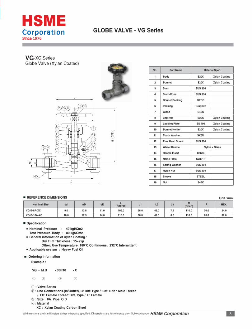
GLOBE VALVE - VG Series
No. Part Name Material Spec.
1 Body S20C C3771
2 Bonnet S20C C3604
3 Stem SUS 304 SUS 304
4 Bonnet Packing C1100 C1100
5 Bonnet Support C3604 C3604
6 Lower Packing PTFE PTFE
7 Upper Packing PTFE PTFE
8 Gland C3604 C3604
9 Cap Nut S20C C3604
10 Locking Plate SS 400 SS 400
11 Bonnet Holder S20C S20C
12 Tooth Washer SK5M SK5M
13 Plus Head Screw SUS 304 SUS 304
14 Wheel Handle Nylon + Glass
15 Handle Insert C3604 C3604
16 Name Plate C2801P C3801P
17 Spring Washer SUS 304 SUS 304
18 Nylon Nut SUS 304 SUS 304
19 Sleeve STEEL C3604
20 Nut S45C C3604
Nominal Size ¢d øD ¢E L(Approx) L1 L2 L3 H
(Open)T
(Thread)R HEX.
VG-B-15-C 10.0 15.0 12.0 110.0 36.0 49.0 7.5 110.0 - 70.0 27.0
VG-MB-M24P215-C 9.0 15.0 12.0 99.6 36.0 51.0 14.0 110.0 M24*2.0 70.0 27.0
VG-B-16-C 10.0 16.0 13.0 100.0 36.0 49.0 7.5 110.0 - 70.0 30.0
VG-MB-06G16-C 10.0 16.0 13.0 100.0 36.0 51.0 16.0 110.0 3/4”PF 70.0 30.0
VG-MB-06R16-C 10.0 16.0 13.0 100.0 36.0 51.0 20.0 110.0 3/4”PT 70.0 30.0
VG-B-20-C 12.0 20.0 16.0 110.0 36.0 49.0 8.0 110.0 - 70.0 36.0
VG-MB-02R20-C 6.0 20.0 16.0 94.0 36.0 45.0 14.0 110.0 1/4”PT 70.0 36.0
VG-MB-03R20-C 10.5 20.0 16.0 97.0 36.0 47.0 16.0 110.0 3/8”PT 70.0 36.0
VG-MB-04R20-C 10.5 20.0 16.0 97.0 36.0 48.0 17.0 110.0 1/2”PT 70.0 36.0
VG-MB-06R20-C 12.0 20.0 16.0 100.0 36.0 51.0 20.0 110.0 3/4”PT 70.0 36.0
VG-B-MB-08R20-C 12.0 20.0 16.0 96.0 42.0 45.0 22.0 100.0 1” PT 70.0 36.0
VG-B-25-C 12.0 25.0 20.0 103.5 38.0 38.0 10.0 113.0 - 70.0 41.0
VG-B-8A-C 9.0 13.8 11.0 109.0 36.0 49.0 7.5 110.0 - 70.0 24.0VG-B-10A-C 10.0 17.3 14.0 110.0 36.0 49.0 8.0 110.0 - 70.0 32.0VG-MB-03R10A-C 8.0 17.3 14.0 97.0 36.0 48.0 16.0 110.0 3/8”PT 70.0 32.0
VGGlobe Valve
REFERENCE DIMENSIONS Unit :mm

all dimensions are in millimeters unless otherwise specified. Dimensions are for reference only. Subject change. HSME Corporation2
GLOBE VALVE - VG Series
Specification
Ordering Information
Nominal Pressure : 40 kgf/Cm2 Shell Test : 80 kgf/Cm2 Maximum Working Temperature : 160°C Application sytem : Fuel Oil, Lub Oil, Fresh Water, Steam
Example :
VG - M B - 03R10 - C ① ② ③ ④ ① : Valve Series ② : End Connections.(In/Outlet), B: Bite Type / BM: Bite * Male Thread / FB: Female Thread*Bite Type / F: Female ③ : Size PT3/8”*10mm Tube O.D
Nominal Size ¢d øD ¢E L(Approx) L1 L2 L3 H
(Open)T
(Thread)R HEX.
VG-MB-04R10A-C 10.0 17.3 14.0 97.0 36.0 48.0 17.0 110.0 1/2”PT 70.0 32.0
VG-MB-06G10A-C 10.0 17.3 14.0 100.0 36.0 51.0 16.0 110.0 3/4”PF 70.0 32.0
VG-B-15A-C 12.0 21.7 18.0 110.0 37.0 46.0 9.0 110.0 - 70.0 36.0
VG-MB-03R15A-C 8.0 21.7 18.0 97.5 37.0 47.0 16.0 110.0 3/8”PT 70.0 36.0
VG-MB-04R15A-C 10.5 21.7 18.0 97.5 37.0 48.0 17.0 110.0 1/2”PT 70.0 36.0
VG-MB-06R15A-C 12.0 21.7 18.0 97.5 37.0 51.0 20.0 110.0 3/4”PT 70.0 36.0
VG-MB-08R15A-C 12.0 21.7 18.0 97.5 42.0 45.0 22.0 113.0 1” PT 70.0 36.0
Thread 1/8” 1/4” 3/8” 1/2” 3/4” 1”
Designator 01R (G) 02R (G) 03R (G) 04R (G) 06R (G) 08R (G)
Inch Pipe (JIS) 1/8” 1/4” 3/8” 1/2” 3/4” 1”
Designator 6A 8A 10A 15A 20A 25A
Metric Tube 6 8 10 12 15 20
Designator 06 08 10 12 15 20
* ISO/BSP
*Tube
④ : Material C : Carbon Steel B : Brass S4 : Stainless Steel 304
3all dimensions are in millimeters unless otherwise specified. Dimensions are for reference only. Subject change. HSME Corporationall dimensions are in millimeters unless otherwise specified. Dimensions are for reference only. Subject change. HSME Corporation
Thread 1/8” 1/4” 3/8” 1/2” 3/4” 1”
Designator 01R (G) 02R (G) 03R (G) 04R (G) 06R (G) 08R (G)
Inch Pipe (JIS) 1/8” 1/4” 3/8” 1/2” 3/4” 1”
Designator 6A 8A 10A 15A 20A 25A
Metric Tube 6 8 10 12 15 20
Designator 06 08 10 12 15 20
GLOBE VALVE - VG Series
No. Part Name Material Spec.
1 Body S20C Xylan Coating
2 Bonnet S20C Xylan Coating
3 Stem SUS 304
4 Stem-Cone SUS 316
5 Bonnet Packing SPCC
6 Packing Graphite
7 Gland S45C
8 Cap Nut S20C Xylan Coating
9 Locking Plate SS 400 Xylan Coating
10 Bonnet Holder S20C Xylan Coating
11 Tooth Washer SK5M
12 Plus Head Screw SUS 304
13 Wheel Handle Nylon + Glass
14 Handle Insert C3604
15 Name Plate C2801P
16 Spring Washer SUS 304
17 Nylon Nut SUS 304
18 Sleeve STEEL
19 Nut S45C
Nominal Size ¢d øD ¢E L(Approx) L1 L2 L3 H
(Open) R HEX.
VG-B-8A-XC 9.0 13.8 11.0 109.0 36.0 49.0 7.5 110.0 70.0 24.0
VG-B-10A-XC 10.0 17.3 14.0 110.0 36.0 49.0 8.0 110.0 70.0 32.0
REFERENCE DIMENSIONS
Specification
Unit :mm
VG-XC SeriesGlobe Valve (Xylan Coated)
Ordering Information
Nominal Pressure : 40 kgf/Cm2Test Pressure Body : 80 kgf/Cm2General information of Xylan Coating.: Dry Film Thickness : 15~25µ Other: Use Temperature: 180°C Continuous; 232°C Intermittent.Applicable system : Heavy Fuel Oil
Example :
VG - M B - 03R10 - C ① ② ③ ④ ① : Valve Series ② : End Connections.(In/Outlet), B: Bite Type / BM: Bite * Male Thread / FB: Female Thread*Bite Type / F: Female ③ : Size 8A Pipe O.D④ : Material XC : Xylan Coating Carbon Steel

Hydraulic Jack Up Unit Ultra High Working Pressure Design: Up to 1300 bar
HSME is the leading supplier of Hydraulic Powered JACK UP UNITs. HSME provides the complete bolting solution for heavy industries including diesel engine fabrication where long stub bolts need to be tightened enough to hold up massive weight of engine sectional blocks or parts in place
HSME supplies wide range of Hydraulic Jack Up Units that handle bolts up to M90 metric thread.
all dimensions are in millimeters unless otherwise specified. Dimensions are for reference only. Subject change. HSME Corporation2
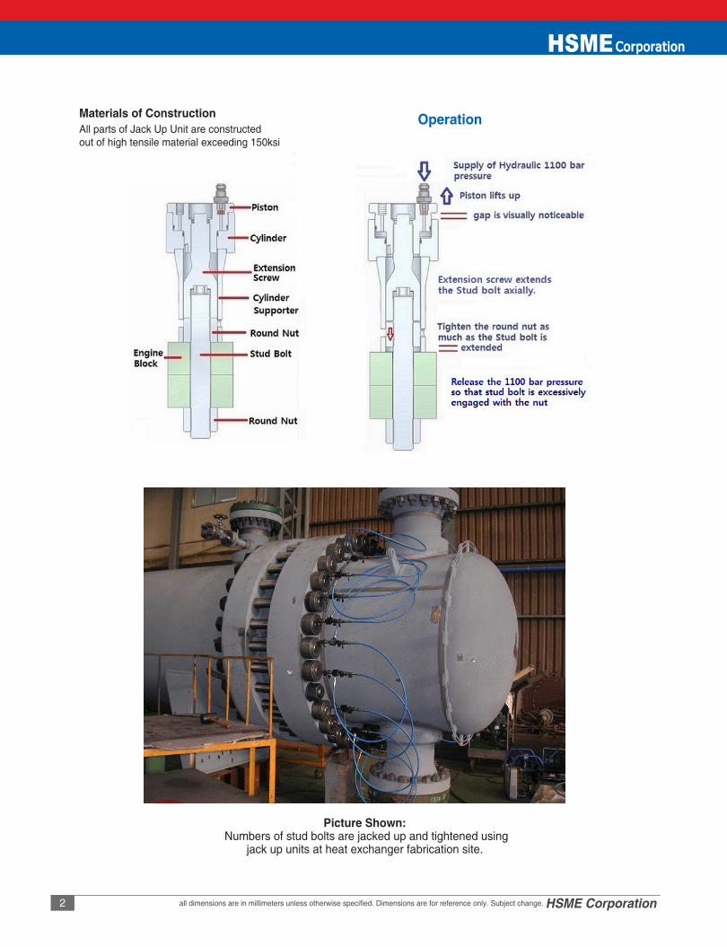
Materials of Construction OperationAll parts of Jack Up Unit are constructed out of high tensile material exceeding 150ksi
Picture Shown: Numbers of stud bolts are jacked up and tightened using
jack up units at heat exchanger fabrication site.

all dimensions are in millimeters unless otherwise specified. Dimensions are for reference only. Subject change. HSME Corporation 3all dimensions are in millimeters unless otherwise specified. Dimensions are for reference only. Subject change. HSME Corporation
Hydraulic Jack-THS
Hydraulic Jack - THS Series
Assembly
Extension~
Type 1
Type 4
Type 7
Type 1 Type 2 Type 3
Type 8
Type 9 Type 10
Type 5
Type 2 Type 3 Type 6

Hydraulic Jack - THS Series
4 www.hsmecorp.com
Assembly Code SIZEHydraulic Jack
MAT’LExtension
MAT’LD L TYPE D L TYPE
THS-H1728-M24-10 M24*2 83 69 3 SNCM439 - - - -
THS-H1728-M27-10 M27*2 83 69 3 SNCM439 - - - -
THS-H1728-M30-10 M30*2 98 76 3 SNCM439 52 140 2 SNCM439
THS-H2132-M20-10 M20*1.5 64 76 1 SNCM439 32 114 1 SNCM439
THS-H2132-M30-10 M30*2 103 76 2 SNCM439 52 160 1 SNCM439
THS-H2132-M39-10 M39*2 113 72 3 SNCM439 64 185 2 SNCM439
THS-H2533-M22-11 M22*1.5 73 66 2 SNCM439 34 96 1 SNCM439
THS-H2533-M36-22 M36*2 107 71 3 SNCM439 - - - -
THS-H2533-M39-22 M39*3 128 71 3 SNCM439 64 167 1 SNCM439
THS-H3240-M33-33 M33*2 77 146 4 SNCM439 59 81 3 SNCM439
THS-H3240-M36-12 M36*2 107 71 3 SNCM439 - - - -
THS-H3240-M39-22 M39*3 128 71 3 SNCM439 64 167 1 SNCM439
THS-H3240-M48-22 M48*3 145 71 3 SNCM439 82 300 2 SNCM439
THS-L2330-M33-10 M33*2 111 61 7 SNCM439 - - - -
THS-L2330-M39-10 M39*4 110 160 5 SCM440 - - - -
THS-L2330-M45-10 M45*3 126 54 7 SCM440 - - - -
THS-L2832-M39-23 M39*3 135 59 7 SCM440H - - - -
THS-H4660-M45-11 M45*3 140 110 6 SCM435 - - - -
THS-H4660-M56-11 M56*5.5 165 75 7 SCM440 - - - -
THS-H4660-M72-10 M72*6 210 77 6 SCM440 - - - -
THS-H4660-M90-11 M90*6 260 91 8 SCM440 - - - -
THS-L70ME-M80-10 M80*6 215 140 10 SCM440 - - - -
THS-G50ME-M48-12 M48*5 130 101 9 SCM440 - - - -
Hydraulic Jack-THS
Reference Dimensions. (Hyd.Jack Parts)

5www.hsmecorp.com
Assembly Code SIZESupport-1
MAT’LSupport-2
MAT’LD L TYPE D L TYPE
THS-H1728-M24-10 M24*2 67 34 1 SNCM439 - - - -
THS-H1728-M27-10 M27*2 67 43 1 SNCM439 - - - -
THS-H1728-M30-10 M30*2 79 41 1 SNCM439 79 135 1 SNCM439
THS-H2132-M20-10 M20*1.5 - - - - 54 100 2 SNCM439
THS-H2132-M30-10 M30*2 79 43 1 SNCM439 79 143 3 SNCM439
THS-H2132-M39-10 M39*2 104 51 1 SNCM439 104 175 4 SNCM439
THS-H2533-M22-11 M22*1.5 - - - - 55 80 3 SNCM439
THS-H2533-M36-22 M36*2 85 51 4 SNCM439 85 140 2 SNCM439
THS-H2533-M39-22 M39*2 100 67 4 SNCM439 100 164 2 SNCM439
THS-H3240-M33-33 M33*2 74 87 4 SNCM439 - - - -
THS-H3240-M36-12 M36*2 85 51 4 SNCM439 - - - -
THS-H3240-M39-22 M39*3 101 55 4 SNCM439 - - - -
THS-H3240-M48-22 M48*3 125 68 1 SNCM439 125 285 2 SNCM439
THS-L2330-M33-10 M33*2 105 47 1 SNCM439
THS-L2330-M39-10 M39*4 - - - - - - - -
THS-L2330-M45-10 M45*3 105 112 3 SNCM439 - - - -
THS-L2832-M39-23 M39*3 125 53 2 SCM440H - - - -
THS-H4660-M45-11 M45*3 105 112 4 SNCM439 - - - -
THS-H4660-M56-11 M56*5.5 165 63 4 SCM440 - - - -
THS-H4660-M72-10 M72*6 190 79 4 SNCM439 - - - -
THS-H4660-M90-11 M90*6 220 103 5 SCM440 - - - -
THS-L70ME-M80-10 M80*6 205 105 4 SCM440 - - - -
THS-G50ME-M48-12 M48*5 125 75 4 SCM440 - - - -
Support-1
Support-2
Reference Dimensions. (Support Parts)
Type 1
Type 1
Type 2
Type 2
Type 3
Type 3
Type 4
Type 4
Type 5
Type 5

Hydraulic Jack - THS Series
6 www.hsmecorp.com
Technical Datas.
Assembly Code SIZE TYPE(Engine)
TESTPRESSURE
(bar)MAX.LIFT
(mm) Applications REMARK
THS-H1728-M24-10 M24*2H17/28
H17/28E(U)1300 10
H17/28 M.B.C SIDE STUD : 900bar CON-ROD BIG-END STUD:900barH17/28E(U) CYL.HEAD STUD:900bar
THS-H1728-M27-10 M27*2H17/28
H17/28E(U)1300 10
H17/28 FLYWHEEL STUD : 1100barH17/28E(U) M.B.C STUD:1100bar
THS-H1728-M30-10 M30*2 H17/28 1300 10 CYL.HEAD STUD:1150bar M.B.C STUD:1150bar
THS-H2132-M20-10 M20*1.5 H21/32 1300 10 CON-ROD SHAFT STUD:1150bar
THS-H2132-M30-10 M30*2 H21/32 1500 10 CON-ROD STUD:950bar M.B.C Side Bolt:850bar FLYWHEEL STUD : 1050bar C/Weight STUD : 850bar
THS-H2132-M39-10 M39*2 H21/32 1500 10 CYL.HEAD STUD:1100bar M.B.C STUD:1200bar
THS-H2533-M22-11 M22*1.5 H25/33 1500 10 CON-ROD SHAFT :1100bar
THS-H2533-M36-22 M36*2
H25/33,
H32/40 1500 10
H25/33 M.B.C SIDE:950bar CON-ROD BIG-END:1100bar FLYWHEEL STUD : 1000bar C/Weight STUD : 850barH32/40 ENGINE BLOCK COUPLING STUD:1200bar
THS-H2533-M39-22 M39*2
H25/33,
H32/40 1500 10
H25/33 M.B.C STUD:1200bar CYL.HEAD STUD:900barH32/40 M.B.C SIDE BOLT:900bar C/Weight STUD : 1000bar
THS-H3240-M33-33 M33*2 H32/40 1200 3.5 BIG END(M33):1100bar SHAFT:1100bar
THS-H3240-M36-12 M36*2 H25/33,
H32/401500 10
H25/33 M.B.C SIDE:950bar CON-ROD BIG-END:1100bar FLYWHEEL STUD : 1000bar C/Weight STUD : 850barH32/40 ENGINE BLOCK COUPLING STUD:1200bar
THS-H3240-M39-22 M39*3H25/33,
H32/401500 10
H25/33 M.B.C STUD:1200bar CYL.HEAD STUD:900barH32/40 M.B.C SIDE BOLT:900bar C/Weight STUD : 1000bar
THS-H3240-M48-22 M48*3 H3240 1500 10 M.B.C STUD:1200bar CYL.HEAD STUD:1150bar
THS-L2330-M33-10 M33*2L23/30,
L23/30DH1050 10 L23/30 :700bar
L23/30DH:700bar
THS-L2330-M39-10 M39*4L23/30,
L23/30DH1050 10 L23/30 :700bar
L23/30DH:750bar
THS-L2330-M45-10 M45*3 L23/30 1050 6 WORKING PRESSURE :700bar
THS-L2832-M39-23 M39*3 L28/32 1050 6 WORKING PRESSURE :700bar
THS-H4660-M45-11 M45*3 H46/60 1500 10 WORKING PRESSURE :1100bar
THS-H4660-M56-11 M56*5.5 H46/60 1700 10 WORKING PRESSURE :1500bar
THS-H4660-M72-10 M72*6 H46/60 1700 10 WORKING PRESSURE :1500bar
THS-H4660-M90-11 M90*6 H46/60 2000 15 WORKING PRESSURE :1250/1700bar
THS-L70ME-M80-10 M80*6 L70ME 2000 15 WORKING PRESSURE :1500bar End chock bolts
THS-G50ME-M48-12 M48*5 G50ME 2000 10 WORKING PRESSURE :1500bar
Exhaust Valve, Turning Wheel