thermal energy storage for low and medium temperature ... · loughborough university institutional...
TRANSCRIPT

Loughborough UniversityInstitutional Repository
Thermal energy storage forlow and medium temperature
applications using phasechange materials � a review
This item was submitted to Loughborough University's Institutional Repositoryby the/an author.
Citation: PEREIRA DA CUNHA, J. and EAMES, P., 2016. Thermal en-ergy storage for low and medium temperature applications using phase changematerials � a review. Applied Energy, 177, pp. 227 - 238.
Additional Information:
• This paper was accepted for publication in the journal Ap-plied Energy and the definitive published version is available athttp://dx.doi.org/10.1016/j.apenergy.2016.05.097
Metadata Record: https://dspace.lboro.ac.uk/2134/21639
Version: Accepted for publication
Publisher: c© Elsevier
Rights: This work is made available according to the conditions of the Cre-ative Commons Attribution-NonCommercial-NoDerivatives 4.0 International(CC BY-NC-ND 4.0) licence. Full details of this licence are available at:https://creativecommons.org/licenses/by-nc-nd/4.0/
Please cite the published version.

THERMAL ENERGY STORAGE FOR LOW AND MEDIUM TEMPERA-1
TURE APPLICATIONS USING PHASE CHANGE MATERIALS 2
- A REVIEW 3
Jose Pereira da Cunha, [email protected], Centre for Renewable Energy Systems 4 Technology (CREST); Loughborough University, Loughborough (Leicestershire) LE11 3TU, United 5 Kingdom; 6 Philip Eames, [email protected], Centre for Renewable Energy Systems Technology (CREST); 7 Loughborough University, Loughborough (Leicestershire) LE11 3TU, United Kingdom; 8 9
10 ABSTRACT 11
12 A comprehensive review of phase change materials (PCMs) with phase transition temperatures be-13 tween 0 and 250 °C is presented. From that review, organic compounds and salt hydrates seem more 14 promising below 100 °C and eutectic mixtures from 100 to 250 °C. 15 Practical indirect heat exchanger designs for latent heat storage systems were also assessed and feasi-16 ble heat enhancement mechanisms reviewed. The focus on this temperature range is due to potential 17 CO2 emissions reduction able to be achieved replacing conventional heating and cooling applications 18 in the domestic, commercial and public administration sectors, which represented around a quarter of 19 the UK’s final energy consumption in 2015. 20 21 Keywords: 22 Phase change materials, Thermal Energy storage, Inorganic PCMs, Organic PCMs, Eutectic PCMs, 23 Latent Heat Storage. 24
1. INTRODUCTION 25 26 To date, the measures adopted to stabilize global temperature rise below the 2°C target, are likely to 27 be insufficient [1]. If this target is to be achieved, there must be an increased effort to de-carbonize 28 global energy consumption, which still relies heavily on fossil fuel sources. 29 Conventional heating and cooling in the domestic, commercial and public administration sectors had a 30 combined natural gas and petroleum products consumption of around 25% of the UK’s final energy 31 consumption in 2014 [2]. The distribution per sector is presented in Figure 1. 32
33 Figure 1- The UK's final energy consumption aggregated values for 2014 [2] by source in the Domestic, Commercial 34 and Public Administration sectors. 35

36 To reduce the CO2 emissions in the domestic heating sector, heat pumps could be used as an alterna-37 tive to current fossil fuel burning systems; however, their usage should the restricted to off peak times 38 (between 22.00 and 07.00), in order not to greatly increase the UK’s electrical grid peak demand [3], 39 Figure 2, with local heat storage being used to meet heat demand at other times. . 40 The daily variation of CO2 emissions per kWh of electricity consumed for the 15th of January and 41 July of 2015 are presented in Figure 2, values were obtained for the generation mix for the UK na-42 tional grid and CO2 emission factors applied similar to those estimated by Hawkes et al [4]. In order 43 to match the CO2 emissions associated with grid electricity to natural gas used for space heating 44 (204.9 gCO2/kWh [2]), the minimum coefficient of performance (COP) required for heat pumps is 45 approximately 2. 46 47
48 Figure 2 – Seasonal and hourly variation of CO2 emissions associated with the electricity supplied by the UK nation-49 al grid - sample date:15/01/2015 & 15/07/2015[4], [5]. 50 51 The use of solar thermal systems is another potential way of reducing CO2 emissions associated with 52 space and water heating, effective thermal energy storage will be essential to address the mismatch 53 between the intermittent solar heat supply and the heat demand. [6], [7]. 54 Thermal energy storage can be achieved through 3 distinct ways: sensible; latent or thermochemical 55 heat storage. Sensible heat storage relies on the material's specific heat capacity. Latent heat storage 56 relies on the material's phase change enthalpy to store heat within a narrow temperature range, provid-57 ing greater energy density [kWhth/m3] than that achievable with sensible heat storage over the same 58 temperature gradient; however, volumetric expansions during the melting process can reach 10 to 59 15% for some materials. Thermochemical heat storage is more energetic than latent heat storage, but 60 since it relies on adsorption / desorption or other chemical reactions, reaction kinetics and reactor 61 design significantly determine their actual performance, and require distinct charging and discharging 62 temperatures [8] (usually between 100 and 300 °C, depending on the reaction), having potential inter-63 est for interseasonal storage applications. Figure 3 A shows , heat storage capacity [kWhth/m3] of wa-64 ter sensible heat storage and 3 PCMs over a 20 °C temperature interval; the PCMs store around 2.5 to 65 6 times more energy than water.. Figure 3 B compares thermochemical heat storage to a packed 66 rock bed heat storage system; the hydration of the thermochemical compound can theoretically re-67 lease25 times more energy than what achievable with 40°C of air temperature increase in a rock bed 68 heat storage system, although temperatures up to 120°C are required for dehydration of the salt hy-69 drate ;, such thermochemical heat storage materials may prove to be suitable candidates for inter sea-70 sonal thermal energy storage. 71

72 Figure 3- Heat stored vs. Temperature diagrams for 3 PCMs and a sensible water heat storage system (A) and mag-73 nesium sulphate heptahydrate (data retrieved from Zondag et al. [8]) compared to a conventional rock bed storage 74 system (B). 75 76 Medium and large scale systems such as centralized cooling (absorption chillers [9], [10], [11]) and 77 district heating networks [12]-[13], used commonly in hospitals, commercial centres and office build-78 ings could also benefit from latent heat storage systems, when supplied by solar thermal collectors. 79 Another potential application for latent heat storage would be integration into solar thermal driven 80 organic rankine cycles (ORC) [14]. The characterization of a compact ORC system for low grade 81 transient solar energy conversion was made by [15], and it was concluded that adding latent heat 82 thermal energy storage could potentially stabilize the system to short term weather irregularities 83 (clouds, fog, etc) or even depending on the storage size, be able to maintain daily production. 84 Latent heat energy storage may also have use in industry when integrated in some thermal batch pro-85 cesses, potentially reducing sensible heat losses in the heating and cooling process necessary to 86 achieve optimum process temperatures [9], and allowing heat to be stored between cycles. Such batch 87 processes can be found in most of the food and beverages industry (beer, milk, chocolate, cheese, cof-88 fee, canned food) and industrial drying processes. The possible integration of solar thermal collectors 89 into some common industrial applications in Cyprus was presented by Kalogirou [16]. 90 For nominal operation of latent heat storage systems, the PCM must have a relative high latent heat of 91 fusion, stability in its molten state and be chemically inert with its enclosure. Another important re-92 quirement would be a low degree of subcooling; else their enhanced heat capacity won’t be fully real-93 ised . One of the main properties of commonly used PCMs is their low thermal conductivity, usually 94 between 0.2 and 0.7 [W/m.K], requiring the use of complex heat exchanger geometries to obtain re-95 quired heat transfer rates from latent heat storage containers. Conventional techniques to overcome 96 the low heat transfer characteristic rates would be the used of metal fins [17]; however novel promis-97 ing techniques such as carbon cloths [18], shape stabilized PCMs with graphite [19], [20] microen-98 capsulated-PCM slurries [21] and direct contact latent heat storage systems [22], [23] can also be used 99 to increase the global UA value of latent heat storage systems. 100 101
2. PHASE CHANGE MATERIALS LITERATURE REVIEW 102 103 In order to assess the potential of latent heat storage applications, a comprehensive review of the 104 PCMs physical properties during phase change is critical. For a comparative economic evaluation, 105 market prices for industrial grade materials were used to provide a common approach. 106
107
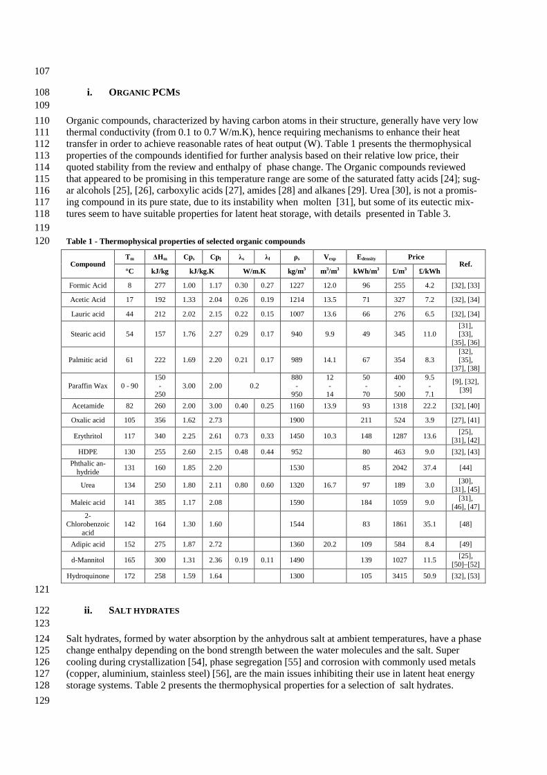
i. ORGANIC PCMS 108 109 Organic compounds, characterized by having carbon atoms in their structure, generally have very low 110 thermal conductivity (from 0.1 to 0.7 W/m.K), hence requiring mechanisms to enhance their heat 111 transfer in order to achieve reasonable rates of heat output (W). Table 1 presents the thermophysical 112 properties of the compounds identified for further analysis based on their relative low price, their 113 quoted stability from the review and enthalpy of phase change. The Organic compounds reviewed 114 that appeared to be promising in this temperature range are some of the saturated fatty acids [24]; sug-115 ar alcohols [25], [26], carboxylic acids [27], amides [28] and alkanes [29]. Urea [30], is not a promis-116 ing compound in its pure state, due to its instability when molten [31], but some of its eutectic mix-117 tures seem to have suitable properties for latent heat storage, with details presented in Table 3. 118 119 Table 1 - Thermophysical properties of selected organic compounds 120
Compound Tm ΔHm Cps Cpl λs λl ρs Vexp Edensity Price
Ref. °C kJ/kg kJ/kg.K W/m.K kg/m3 m3/m3 kWh/m3 £/m3 £/kWh
Formic Acid 8 277 1.00 1.17 0.30 0.27 1227 12.0 96 255 4.2 [32], [33]
Acetic Acid 17 192 1.33 2.04 0.26 0.19 1214 13.5 71 327 7.2 [32], [34]
Lauric acid 44 212 2.02 2.15 0.22 0.15 1007 13.6 66 276 6.5 [32], [34]
Stearic acid 54 157 1.76 2.27 0.29 0.17 940 9.9 49 345 11.0 [31], [33],
[35], [36]
Palmitic acid 61 222 1.69 2.20 0.21 0.17 989 14.1 67 354 8.3 [32], [35],
[37], [38]
Paraffin Wax 0 - 90 150
- 250
3.00 2.00 0.2 880
- 950
12 -
14
50 -
70
400 -
500
9.5 -
7.1
[9], [32], [39]
Acetamide 82 260 2.00 3.00 0.40 0.25 1160 13.9 93 1318 22.2 [32], [40]
Oxalic acid 105 356 1.62 2.73 1900 211 524 3.9 [27], [41]
Erythritol 117 340 2.25 2.61 0.73 0.33 1450 10.3 148 1287 13.6 [25], [31], [42]
HDPE 130 255 2.60 2.15 0.48 0.44 952 80 463 9.0 [32], [43] Phthalic an-
hydride 131 160 1.85 2.20 1530 85 2042 37.4 [44]
Urea 134 250 1.80 2.11 0.80 0.60 1320 16.7 97 189 3.0 [30], [31], [45]
Maleic acid 141 385 1.17 2.08 1590 184 1059 9.0 [31], [46], [47]
2-Chlorobenzoic
acid 142 164 1.30 1.60 1544 83 1861 35.1 [48]
Adipic acid 152 275 1.87 2.72 1360 20.2 109 584 8.4 [49]
d-Mannitol 165 300 1.31 2.36 0.19 0.11 1490 139 1027 11.5 [25], [50]–[52]
Hydroquinone 172 258 1.59 1.64 1300 105 3415 50.9 [32], [53]
121
ii. SALT HYDRATES 122 123 Salt hydrates, formed by water absorption by the anhydrous salt at ambient temperatures, have a phase 124 change enthalpy depending on the bond strength between the water molecules and the salt. Super 125 cooling during crystallization [54], phase segregation [55] and corrosion with commonly used metals 126 (copper, aluminium, stainless steel) [56], are the main issues inhibiting their use in latent heat energy 127 storage systems. Table 2 presents the thermophysical properties for a selection of salt hydrates. 128 129

Table 2 - Thermophysical properties of selected salt hydrates; 130
Compound Tm ΔHm Cps Cpl λs λl ρs Vexp Edensity Price
Ref. °C kJ/kg kJ/kg.K W/m.K kg/m3 m3/m3 kWh/m3 £/m3 £/kWh
Water 0 333 3.30 4.18 1.60 0.61 920 -8.7 109 0 0.0 [32], [57] Calcium Chloride
Hexahydrate 30 125 1.42 2.20 1.09 0.53 1710 11 64 93 2 [9], [32], [56], [58]
Sodium Sulphate Decahydrate 32 180 1.93 2.80 0.56 0.45 1485 4 82 48 1 [9], [32],
[56] Sodium Thiosulfate
Pentahydrate 46 210 1.46 2.39 0.76 0.38 1666 6 103 199 3 [32], [43], [59]
Sodium Acetate Trihydrate 58 266 1.68 2.37 0.43 0.34 1450 3 113 233 3 [32], [60],
[61] Barium Hydroxide
Octahydrate 78 280 1.34 2.44 1.26 0.66 2180 11 171 422 4 [32], [62], [63]
Magnesium Nitrate Hexahydrate 89 140 2.50 3.10 0.65 0.50 1640 5 74 131 3 [9], [32],
[54] Oxalic acid Dihy-
drate 105 264 2.11 2.89 0.90 0.70 1653 0 133 339 4 [31], [41] Magnesium Chlo-ride Hexahydrate 117 150 2.00 2.40 0.70 0.58 1570 8 72 56 1 [32], [54],
[64] 131
a. PHASE SEPARATION 132 133 Water separation, related to poor molecular bonding [55], [64] is the main factor determining thermal 134 stability in the molten phase. Suitable encapsulation could help reduce the effects of water segrega-135 tion, since it would prevent the release of partially evaporated water. 136
b. SUPER COOLING 137 138 The onset of solidification can occur at a significantly lower temperature than the melting point, nor-139 mally around10 to 20 °C [37]. Adding other salts with similar crystal structures, increases nucleation 140 points, and may reduce this phenomenon. A study of Magnesium chloride hexahydrate [64], proved 141 that the addition of Strontium Carbonate, Strontium Hydroxide and Magnesium Hydroxide effectively 142 reduced super cooling for this salt. 143 144
iii. EUTECTIC PCMS 145 146 Binary and ternary mixtures of inorganic salts have been widely studied for thermal storage applica-147 tions. Nitrate, chloride and sulphate salts of alkali and alkaline metals, such as magnesium, potassium, 148 lithium and calcium, are the main compounds used to produce medium temperature eutectic mixtures, 149 also known as ionic liquids [65]. 150 Due to their higher density and stability in their liquid state, they have been used widely as ionic liq-151 uids in high temperature sensible thermal storage systems (thermonuclear energy, concentrated solar 152 thermal power [66]–[68]). 153 Due to the lack of experimental data for some of the thermophysical properties of eutectic mixtures, 154 weighting methods have been used to predict missing values [69], [70]. More developed techniques to 155 predict thermophysical properties of eutectic mixtures do exist [71], [72], involving Van Der Waals 156 volumes and surface areas of stable molecular combinations; however, more simplified correlations 157 were used. The weighting correlations used to obtain the thermophysical properties, namely heat ca-158 pacity (Cp), density (ρ), thermal conductivity (λ) and melting enthalpy (ΔHm), are presented in equa-159 tions 1 to 6, which use available properties of the mixture and its constituents, molar ratio (xi), mass 160 ratio (wi) and volumetric ratio (zi) and their melting point (Tm) to predict the unknown values. A 161 comparison was made with some eutectic salts for which experimental data was available; the differ-162 ence between predictions and measurements was less than 10%. Table 3 presents the physical proper-163

ties of the selected eutectic compounds in the 0-250 °C range, with the predicted latent heat values 164 shown in bold. 165 166 167 168 169 170 171 172 173 174 175 176 177 178 179 180 181 182 183 184 Table 3 - Thermophysical properties of selected eutectic compounds 185
Eutectic Compounds
Mass Ratio
Tm ΔHm Cps Cpl λs λl ρs Edensity Price Ref
°C kJ/kg J/kg.K mW/m.K kg/m3 kWh/m3 £/m3 £/kWh CaCl2.(H2O)6
- MgCl2.(H2O)6
67-33 25 127 1620 2270 930 550 1661 57 80 1.4 [32], [43]
Urea -
CH3COONa.(H2O)3 60-40 30 200 1750 2210 630 480 1370 74 206 2.8 [43],
[73]
Mg(NO3)2. (H2O)6 -
NH4NO3 61-39 52 125 2130 2670 590 500 1672 58 188 3.3 [43],
[73]
Urea – Acetamide 38-62 53 224 1920 2660 510 340 1216 73 924 13 [58] Stearic Acid
- Palmitic Acid
36-64 53 182 1720 2230 234 169 971 46 351 8 [74]
Mg(NO3)2. (H2O)6 -
MgCl2. (H2O)6 59-41 59 132 2290 2810 670 530 1610 58 99 1.7
[32], [43]
Stearic Acid -
Acetamide 83-17 65 213 1800 2400 300 180 972 56 485 8.6
LiNO3 -
MgNO3.(H2O)6 14-86 72 180 2380 2900 700 510 1713 84 718 8.5
Urea - LiNO3 82-18 76 218 1770 2020 850 600 1438 84 851 10.1
[73]
Urea - NaNO3 71-29 83 187 1600 2030 750 590 1502 76 220 2.9
Urea - NH4Cl 85-15 102 214 1770 2090 760 580 1348 77 174 2.3
Urea – K2CO3 15-85 102 206 1660 2020 780 580 1415 78 269 3.4
Urea - KNO3 77-23 109 195 1600 1910 810 580 1416 74 255 3.4
Urea – NaCl 90-10 112 230 1720 2020 820 600 1372 85 180 2.1
𝑤𝑤𝑖𝑖 = 𝑥𝑥𝑖𝑖 × 𝑀𝑀𝑖𝑖 × ��𝑥𝑥𝑖𝑖 ×𝑀𝑀𝑖𝑖𝑖𝑖
�−1
𝑧𝑧𝑖𝑖 =𝑤𝑤𝑖𝑖𝜌𝜌𝑖𝑖
× ��𝑤𝑤𝑖𝑖𝜌𝜌𝑖𝑖𝑖𝑖
�−1
1
2
𝐶𝐶𝐶𝐶𝑒𝑒𝑒𝑒𝑒𝑒𝑒𝑒𝑒𝑒𝑒𝑒𝑖𝑖𝑒𝑒 = �𝐶𝐶𝐶𝐶𝑖𝑖 × 𝑤𝑤𝑖𝑖𝑖𝑖
3
𝜌𝜌𝑒𝑒𝑒𝑒𝑒𝑒𝑒𝑒𝑒𝑒𝑒𝑒𝑖𝑖𝑒𝑒 = �𝜌𝜌𝑖𝑖 × 𝑧𝑧𝑖𝑖𝑖𝑖
4
𝜆𝜆𝑒𝑒𝑒𝑒𝑒𝑒𝑒𝑒𝑒𝑒𝑒𝑒𝑖𝑖𝑒𝑒 = �𝜆𝜆𝑖𝑖𝑧𝑧𝑖𝑖
𝑖𝑖
5
∆𝐻𝐻𝑒𝑒𝑒𝑒𝑒𝑒𝑒𝑒𝑒𝑒𝑒𝑒𝑖𝑖𝑒𝑒 = 𝑇𝑇𝑇𝑇𝑒𝑒𝑒𝑒𝑒𝑒𝑒𝑒𝑒𝑒𝑒𝑒𝑖𝑖𝑒𝑒 ×�∆𝐻𝐻𝑖𝑖 × 𝑤𝑤𝑖𝑖𝑇𝑇𝑇𝑇𝑖𝑖𝑖𝑖
6

Urea - KCl 89-11 115 227 1690 1960 830 0.60 1370 83 197 2.4 LiNO3 - NaNO3 -
KNO3 30-18-
52 123 140 1170 1440 790 530 2068 79 1979 25 [75], [76]
LiNO3 - KNO3 34-66 133 150 1170 1350 960 520 2018 82 2167 26 [75]–[77]
KNO3 - NaNO2 56-44 141 97 1180 1740 730 570 1994 52 504 9.7 [78, p.
778]
KNO3 - NaNO3 - NaNO2
53-6-41 142 110 1170 1730 720 570 2006 60 497 8.3
[32], [78, p.
786] KNO2 - NaNO3 48-52 149 124 1050 1630 580 520 2080 70 994 14
[78] LiNO3 - NaNO2 62-38 156 233 1570 1910 1120 660 2296 143 3816 27
LiNO3 – KCl 58-42 160 272 1260 1350 1310 590 2196 161 3409 21 [32], [79] LiNO3 - NaNO3 –
KCl 45-50-
5 160 266 1320 1690 880 590 2297 166 2852 17
HCOONa – HCOOK 45-55 176 175 1150 930 630 430 1913 92 421 4.6 [80]
LiOH - LiNO3 19-81 183 352 1600 2000 1330 690 2124 202 5165 26 [78]
LiNO3 - NaNO3 49-51 194 262 1350 1720 870 590 2317 165 3084 19 [32], [78]
LiNO3 - NaCl 87-13 208 369 1540 1560 1350 630 2350 235 5254 22 [32], [79], [81]
KNO3 - KOH 80-20 214 83 1030 1350 880 540 1905 43 611 14 [32]
KNO3 - NaNO3 55-45 222 110 1010 1490 730 510 2028 61 482 8.0
LiBr - LiNO3 27-73 228 279 1340 1380 1140 570 2603 196 6134 31
[78], [82]
LiOH - NaNO3 – NaOH
6-67-27 230 184 1300 2000 780 670 2154 107 538 5.0
NaNO2 - NaNO3 55-45 233 163 1310 2130 590 640 2210 97 382 3.9
CaCl2 - LiNO3 13-87 238 317 1500 1530 1370 690 2362 204 5325 26
LiCl - LiNO3 9-91 244 342 1580 1610 1370 640 2351 218 6019 28
NaNO3 – NaOH 86-14 250 160 1190 1860 660 600 2241 97 339 3.5 [32]
186
3. POTENTIAL APPLICATIONS FOR INDIRECT LATENT HEAT STORAGE CONTAINERS AND 187 SYSTEMS 188
189 The integration of latent heat storage containers into specific heating or cooling networks can be di-190 vided by the heat transfer fluid used: air or liquid. Using water as the heat transfer fluid, latent heat 191 storage containers and systems could be integrated with conventional domestic central heating sys-192 tems using water radiators, ideal to retrofit when changing a gas boiler for a heat pump [83], as illus-193 trated in Figure 4 A. Using air as the heat transfer fluid, latent heat storage containers and systems can 194 be integrated into centralized ventilation systems, typical in large office areas and commercial build-195 ings, as illustrated in Figure 4 B. 196
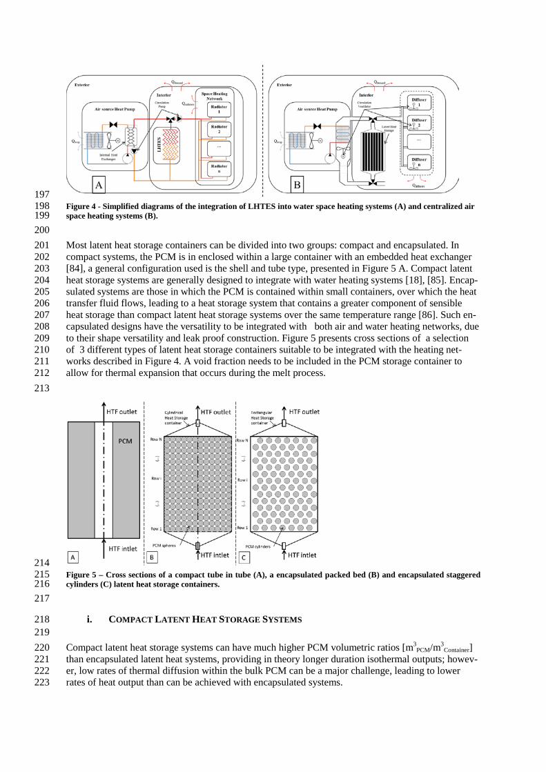
197 Figure 4 - Simplified diagrams of the integration of LHTES into water space heating systems (A) and centralized air 198 space heating systems (B). 199 200 Most latent heat storage containers can be divided into two groups: compact and encapsulated. In 201 compact systems, the PCM is in enclosed within a large container with an embedded heat exchanger 202 [84], a general configuration used is the shell and tube type, presented in Figure 5 A. Compact latent 203 heat storage systems are generally designed to integrate with water heating systems [18], [85]. Encap-204 sulated systems are those in which the PCM is contained within small containers, over which the heat 205 transfer fluid flows, leading to a heat storage system that contains a greater component of sensible 206 heat storage than compact latent heat storage systems over the same temperature range [86]. Such en-207 capsulated designs have the versatility to be integrated with both air and water heating networks, due 208 to their shape versatility and leak proof construction. Figure 5 presents cross sections of a selection 209 of 3 different types of latent heat storage containers suitable to be integrated with the heating net-210 works described in Figure 4. A void fraction needs to be included in the PCM storage container to 211 allow for thermal expansion that occurs during the melt process. 212 213
214 Figure 5 – Cross sections of a compact tube in tube (A), a encapsulated packed bed (B) and encapsulated staggered 215 cylinders (C) latent heat storage containers. 216 217
i. COMPACT LATENT HEAT STORAGE SYSTEMS 218 219 Compact latent heat storage systems can have much higher PCM volumetric ratios [m3
PCM/m3Container] 220
than encapsulated latent heat systems, providing in theory longer duration isothermal outputs; howev-221 er, low rates of thermal diffusion within the bulk PCM can be a major challenge, leading to lower 222 rates of heat output than can be achieved with encapsulated systems. 223

For domestic and small district water heating requirements, characterized by heating rates tipically 224 below 20 kW, more complex heat exchanger configurations can be used to obtain higher inlet-outlet 225 temperature differentials, since flow head losses are not the main challenge. Figure 6 presents a sche-226 matic diagram of a 18 770 L PCM container modelled by Nakaso et al. [18], with a predicted thermal 227 storage capacity using a paraffin wax with a melting temperature of 49°C (discharged from 53°C to 228 40°C) of 516.7 kWhth. He predicted numerically that without any thermal enhancement, the system 229 could provide a constant 25 kW thermal power output for 80% of its total capacity, around 16h and 32 230 minutes. 231 232
233 Figure 6 –A schematic diagram of the 18 770L compact latent heat storage unit designed by Nakaso et al. [18], com-234 prised of 18 parallel 28mm copper tubes, each having 14 passes through the PCM volume. 235 236 For large process heating requirements, large parallel arrays of tubes should be used, to overcome the 237 heat transfer limitation imposed by the PCMs low thermal conductivity [12], rather than using com-238 plex heat exchanging geometries [18]. This enables the heat transfer path length to be reduced, higher 239 power outputs achieved, reduced heat transfer fluid volume flow rate, and lower frictional head losses. 240 Figure 7 A, illustrates the cross section of a rectangular cross section container with 100 tubes running 241 in parallel for the heat transfer fluid. The proposed system could contain up to 827 L of PCM within a 242 container 2m high with a square cross section of 800mm x 800mm. 243 244
245 Figure 7 – Proposed design for a 827L compact latent heat storage container for process heating applications (A), and 246 the geometrical arrangement and tube spacing (B), studied by Collela et al. [12]. 247
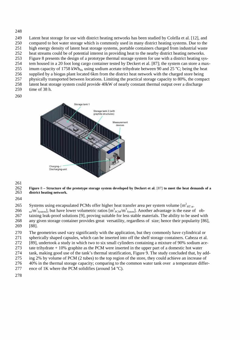
248 Latent heat storage for use with district heating networks has been studied by Colella et al. [12], and 249 compared to hot water storage which is commonly used in many district heating systems. Due to the 250 high energy density of latent heat storage systems, portable containers charged from industrial waste 251 heat streams could be of potential interest in providing heat to the nearby district heating networks. 252 Figure 8 presents the design of a prototype thermal storage system for use with a district heating sys-253 tem housed in a 20 foot long cargo container tested by Deckert et al. [87]; the system can store a max-254 imum capacity of 1758 kWhth, using sodium acetate trihydrate between 90 and 25 °C; being the heat 255 supplied by a biogas plant located 6km from the district heat network with the charged store being 256 physically transported between locations. Limiting the practical storage capacity to 80%, the compact 257 latent heat storage system could provide 40kW of nearly constant thermal output over a discharge 258 time of 38 h. 259 260
261 Figure 8 – Structure of the prototype storage system developed by Deckert et al. [87] to meet the heat demands of a 262 district heating network. 263 264 Systems using encapsulated PCMs offer higher heat transfer area per system volume [m2
HT ar-265 ea/m3
System], but have lower volumetric ratios [m3PCM/m3
Sytem]. Another advantage is the ease of ob-266 taining leak-proof solutions [9], proving suitable for less stable materials. The ability to be used with 267 any given storage container provides great versatility, regardless of size; hence their popularity [86], 268 [88]. 269 The geometries used vary significantly with the application, but they commonly have cylindrical or 270 spherically shaped capsules, which can be inserted into off the shelf storage containers. Cabeza et al. 271 [89], undertook a study in which two to six small cylinders containing a mixture of 90% sodium ace-272 tate trihydrate + 10% graphite as the PCM were inserted in the upper part of a domestic hot water 273 tank, making good use of the tank’s thermal stratification, Figure 9. The study concluded that, by add-274 ing 2% by volume of PCM (2 tubes) to the top region of the store, they could achieve an increase of 275 40% in the thermal storage capacity; comparing to the common water tank over a temperature differ-276 ence of 1K where the PCM solidifies (around 54 °C). 277 278
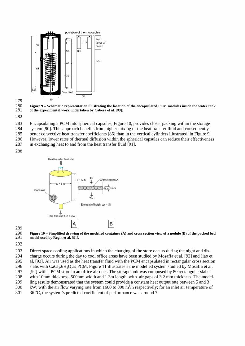
279 Figure 9 – Schematic representation illustrating the location of the encapsulated PCM modules inside the water tank 280 of the experimental work undertaken by Cabeza et al. [89]; 281 282 Encapsulating a PCM into spherical capsules, Figure 10, provides closer packing within the storage 283 system [90]. This approach benefits from higher mixing of the heat transfer fluid and consequently 284 better convective heat transfer coefficients [86] than in the vertical cylinders illustrated in Figure 9. 285 However, lower rates of thermal diffusion within the spherical capsules can reduce their effectiveness 286 in exchanging heat to and from the heat transfer fluid [91]. 287 288
289 Figure 10 – Simplified drawing of the modelled container (A) and cross section view of a nodule (B) of the packed bed 290 model used by Regin et al. [91]. 291 292 Direct space cooling applications in which the charging of the store occurs during the night and dis-293 charge occurs during the day to cool office areas have been studied by Mosaffa et al. [92] and Jiao et 294 al. [93]. Air was used as the heat transfer fluid with the PCM encapsulated in rectangular cross section 295 slabs with CaCl2.6H2O as PCM. Figure 11 illustrates s the modelled system studied by Mosaffa et al. 296 [92] with a PCM store in an office air duct. The storage unit was composed by 80 rectangular slabs 297 with 10mm thickness, 500mm width and 1.3m length, with air gaps of 3.2 mm thickness. The model-298 ling results demonstrated that the system could provide a constant heat output rate between 5 and 3 299 kW, with the air flow varying rate from 1600 to 800 m3/h respectively; for an inlet air temperature of 300 36 °C, the system’s predicted coefficient of performance was around 7. 301

302 Figure 11 – Detailed view of the heat transfer arrangement inside the PCM module (A) and schematic representation 303 of the container integration into the ventilation system studied by Mosaffa et al. [92]. 304 305 Another possible application for an encapsulated latent heat storage system was studied in [94] and is 306 illustrated in figure 12. . Heat from solar thermal collectors is stored in an array of cylinders filled 307 with paraffin wax, , air is used as the heat transfer fluid.. Due to the poor convective heat transfer ob-308 tained to the outer shell of the capsules, aluminium strips were used to increase the effective heat 309 transfer area of the cylinders , providing a substantial increase in the latent heat storage system's effec-310 tiveness and the global solar collector system efficiency. 311 312
313 Figure 12 – Picture of the solar air absorber (A) and schematic diagram of the absorber presenting the thermocou-314 ple positions for the experimental work performed by Reyes et al. [94]. 315 316
a. MICRO ENCAPSULATION OF PCM 317 318 Micro capsules with a diameter varying from around 1-1000 µm [32] have been used to encapsulate 319 PCMs , such micro capsules when introduced into a liquid, form a slurry, effectively increasing the 320 thermal storage capacity of the working fluid and potentially its convective heat transfer properties. 321 Current production methods for micro encapsulated PCMs are: coacervation, suspension and emul-322 sion polymerization, poly-condensation and polyadition. Huang et al. [21], undertook a study in which 323 a cylindrical container filled with a PCM slurry was heated and cooled using a helical coil heat ex-324 changer. The slurry varied between 25, 35 and 50 % composition by volume of PCM capsules to car-325 rier fluid. It was concluded that higher volumetric ratios (50 % respectively) reduced natural convec-326 tion heat transfer within the storage container. Another characteristic of using PCM filled microcap-327 sules was the low PCM volumetric ratios per capsule, normally around 50%, which when multiplied 328 by the slurry volumetric ratio leads to a very low PCM volumetric ratio which reduces the typical 329 heat capacity increase obtained when using PCMs. 330 331
ii. HEAT TRANSFER ENHANCEMENT METHODS 332 333
Most PCMs have low thermal conductivity, which can seriously affect the storage system charge and 334 discharge rates. To address this limitation, extended metal surfaces [84], conductive powders [17] or 335 conductive matrices [18] have proven to be effective in increasing the PCMs heat transport properties, 336 leading to a more uniform temperature within the PCM and better charge and discharge effectiveness 337 for the latent heat storage container/system. 338 339
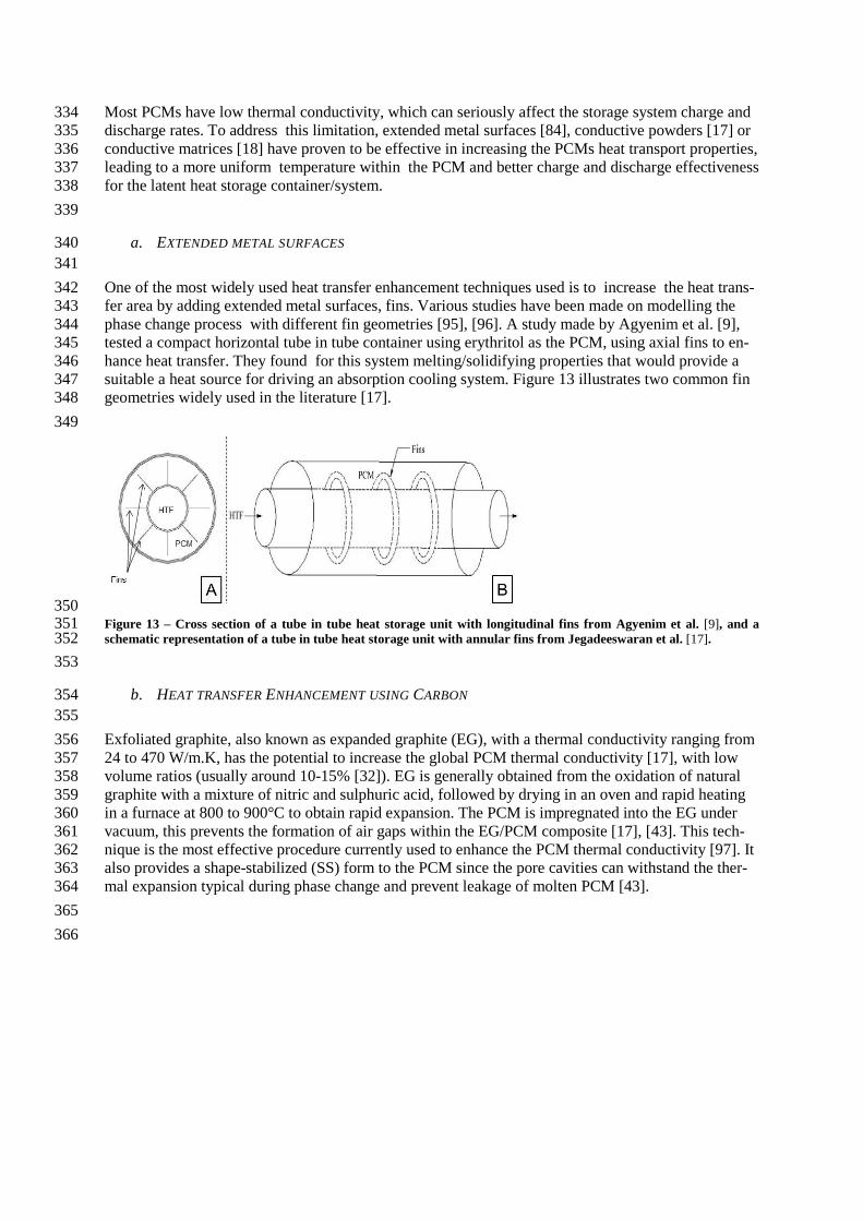
a. EXTENDED METAL SURFACES 340 341 One of the most widely used heat transfer enhancement techniques used is to increase the heat trans-342 fer area by adding extended metal surfaces, fins. Various studies have been made on modelling the 343 phase change process with different fin geometries [95], [96]. A study made by Agyenim et al. [9], 344 tested a compact horizontal tube in tube container using erythritol as the PCM, using axial fins to en-345 hance heat transfer. They found for this system melting/solidifying properties that would provide a 346 suitable a heat source for driving an absorption cooling system. Figure 13 illustrates two common fin 347 geometries widely used in the literature [17]. 348 349
350 Figure 13 – Cross section of a tube in tube heat storage unit with longitudinal fins from Agyenim et al. [9], and a 351 schematic representation of a tube in tube heat storage unit with annular fins from Jegadeeswaran et al. [17]. 352 353
b. HEAT TRANSFER ENHANCEMENT USING CARBON 354 355 Exfoliated graphite, also known as expanded graphite (EG), with a thermal conductivity ranging from 356 24 to 470 W/m.K, has the potential to increase the global PCM thermal conductivity [17], with low 357 volume ratios (usually around 10-15% [32]). EG is generally obtained from the oxidation of natural 358 graphite with a mixture of nitric and sulphuric acid, followed by drying in an oven and rapid heating 359 in a furnace at 800 to 900°C to obtain rapid expansion. The PCM is impregnated into the EG under 360 vacuum, this prevents the formation of air gaps within the EG/PCM composite [17], [43]. This tech-361 nique is the most effective procedure currently used to enhance the PCM thermal conductivity [97]. It 362 also provides a shape-stabilized (SS) form to the PCM since the pore cavities can withstand the ther-363 mal expansion typical during phase change and prevent leakage of molten PCM [43]. 364 365 366
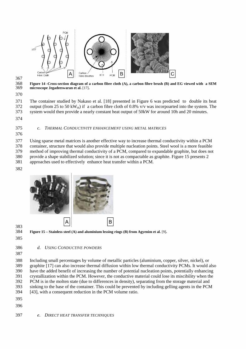
367 Figure 14 -Cross-section diagram of a carbon fibre cloth (A), a carbon fibre brush (B) and EG viewed with a SEM 368 microscope Jegadeeswaran et al. [17]. 369 370 The container studied by Nakaso et al. [18] presented in Figure 6 was predicted to double its heat 371 output (from 25 to 50 kWth) if a carbon fibre cloth of 0.8% v/v was incorpoarted into the system. The 372 system would then provide a nearly constant heat output of 50kW for around 10h and 20 minutes. 373 374
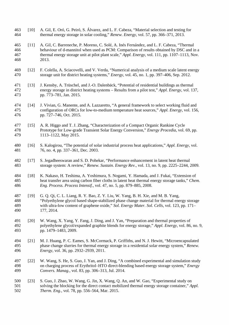
c. THERMAL CONDUCTIVITY ENHANCEMENT USING METAL MATRICES 375 376 Using sparse metal matrices is another effective way to increase thermal conductivity within a PCM 377 container, structure that would also provide multiple nucleation points. Steel wool is a more feasible 378 method of improving thermal conductivity of a PCM, compared to expandable graphite, but does not 379 provide a shape stabilized solution; since it is not as compactable as graphite. Figure 15 presents 2 380 approaches used to effectively enhance heat transfer within a PCM. 381 382
383 Figure 15 – Stainless steel (A) and aluminium lessing rings (B) from Agyenim et al. [9]. 384 385
d. USING CONDUCTIVE POWDERS 386 387 Including small percentages by volume of metallic particles (aluminium, copper, silver, nickel), or 388 graphite [17] can also increase thermal diffusion within low thermal conductivity PCMs. It would also 389 have the added benefit of increasing the number of potential nucleation points, potentially enhancing 390 crystallization within the PCM. However, the conductive material could lose its miscibility when the 391 PCM is in the molten state (due to differences in density), separating from the storage material and 392 sinking to the base of the container. This could be prevented by including gelling agents in the PCM 393 [43], with a consequent reduction in the PCM volume ratio. 394 395 396
e. DIRECT HEAT TRANSFER TECHNIQUES 397

398 Another technique to increase the heat transfer would be to provide direct contact between the heat 399 transfer fluid and the PCM. This would provide an effective increase in heat transfer during the melt-400 ing process since the convective nature of the heat transfer fluid would act directly on the solid PCM 401 phase [20]. Weilong et al. [22] studied the performance of a direct contact latent heat storage contain-402 er using erythritol and an heat transfer oil, Figure 16; and it concluded that at the beginning of the 403 melt process the oil has a low flow rate due to the block of solid erythritol, the top surface of the 404 PCM melts faster than the bottom due to the higher heat transfer rate and the melting time varies sig-405 nificantly with the oil flow rate. 406 407
408 Figure 16 - Temporal variation of the melting process in a direct contact heat transfer container using erythritol as 409 the PCM and oil as the heat transfer fluid, from Weilong et al. [20]. 410 411 To overcome the initial blocking of the fluid flow path when the PCM is in the solid state, Shaopeng 412 et al. [23] studied the insertion of electric heaters, Figure 17, and concluded that the overall energy 413 spent on melting the initial flow pathways was 5% of the total thermal energy stored. 414 415
416 Figure 17 - Schematic cross section showing the locations of the electric heaters in the inlet pipes, studied by 417 Shaopeng et al. [23]. 418 419
4. CONCLUSIONS 420 421 Phase change materials have the potential to store large amounts of energy within a smaller tempera-422 ture range when compared to common sensible heat storage materials. Due to the low thermal con-423 ductivities of many PCMs, poor rates of thermal diffusion within the PCM can seriously affect the 424 storage system charge and discharge rates that can be achieved. 425

A comprehensive review of PCMs melting between 0 and 250°C has been made and the thermophysi-426 cal properties of the materials having the most appropriate properties presented. Below 100 °C, organ-427 ic compounds and salt hydrates are the most interesting materials. Eutectic mixtures with Urea seem 428 promising around 100 °C, and in the range from 130°C up to l 250 °C eutectic mixtures of inorganic 429 salts appear the most promising PCMs. A mixture of sodium and potassium fomates melting around 430 170 °C appears attractive due to is relatively low price and moderate latent heat of fusion. 431 A review of potential indirect latent heat storage containers and systems suitable for integration with 432 various process heating and cooling networks is also reported. Due to its geometrical versatility, en-433 capsulated systems seem more feasible since they can be integrated to any existing system without 434 major technical constrains, although they have lower PCM volume ratios. Compact systems offer 435 larger isothermal stages due to their higher PCM volume ratios; however, heat transfer enhancement 436 among the PCM is imperative to achieve reasonable thermal power output rates, since PCMs thermal 437 conductivity can be a major issue. 438 439
Acknowledgements 440
The research presented in this paper is funded by the EPSRC through Grant reference EP/K011847/1, 441 Interdisciplinary centre for Storage, Transformation and Upgrading of Thermal Energy (i-STUT)E 442 and a Loughborough University funded PhD studentship. 443
444
5. REFERENCES 445
[1] International Energy Agency, “World Energy Outlook 2013,” 2015. 446
[2] K. Harris, A. Annut, and I. MacLeay, Digest of United Kingdom Energy Statistics 2015, vol. b. 447 2015. 448
[3] A. D. Hawkes, “Long-run marginal CO2 emissions factors in national electricity systems,” 449 Appl. Energy, vol. 125, pp. 197–205, Jul. 2014. 450
[4] A. D. Hawkes, “Estimating marginal CO2 emissions rates for national electricity systems,” 451 Energy Policy, vol. 38, no. 10, pp. 5977–5987, Oct. 2010. 452
[5] National Grid, “UK Future Energy Scenarios 2014,” Energy, no. July, p. 220, 2014. 453
[6] D. Haillot, E. Franquet, S. Gibout, and J.-P. Bédécarrats, “Optimization of solar DHW system 454 including PCM media,” Appl. Energy, vol. 109, pp. 470–475, Sep. 2013. 455
[7] M. Ibáñez, L. F. Cabeza, C. Solé, J. Roca, and M. Nogués, “Modelization of a water tank 456 including a PCM module,” Appl. Therm. Eng., vol. 26, pp. 1328–1333, 2006. 457
[8] H. Zondag, B. Kikkert, S. Smeding, R. de Boer, and M. Bakker, “Prototype thermochemical 458 heat storage with open reactor system,” Appl. Energy, vol. 109, pp. 360–365, Sep. 2013. 459
[9] F. Agyenim, N. Hewitt, P. Eames, and M. Smyth, “A review of materials, heat transfer and 460 phase change problem formulation for latent heat thermal energy storage systems (LHTESS),” 461 Renew. Sustain. Energy Rev., vol. 14, pp. 615–628, 2010. 462
[10] A. Gil, E. Oró, G. Peiró, S. Álvarez, and L. F. Cabeza, “Material selection and testing for 463 thermal energy storage in solar cooling,” Renew. Energy, vol. 57, pp. 366–371, 2013. 464
[11] A. Gil, C. Barreneche, P. Moreno, C. Solé, A. Inés Fernández, and L. F. Cabeza, “Thermal 465 behaviour of d-mannitol when used as PCM: Comparison of results obtained by DSC and in a 466 thermal energy storage unit at pilot plant scale,” Appl. Energy, vol. 111, pp. 1107–1113, Nov. 467 2013. 468
[12] F. Colella, A. Sciacovelli, and V. Verda, “Numerical analysis of a medium scale latent energy 469 storage unit for district heating systems,” Energy, vol. 45, no. 1, pp. 397–406, Sep. 2012. 470
[13] J. Kensby, A. Trüschel, and J.-O. Dalenbäck, “Potential of residential buildings as thermal 471 energy storage in district heating systems – Results from a pilot test,” Appl. Energy, vol. 137, 472 pp. 773–781, Jan. 2015. 473
[14] J. Vivian, G. Manente, and A. Lazzaretto, “A general framework to select working fluid and 474 configuration of ORCs for low-to-medium temperature heat sources,” Appl. Energy, vol. 156, 475 pp. 727–746, Oct. 2015. 476
[15] A. R. Higgo and T. J. Zhang, “Characterization of a Compact Organic Rankine Cycle 477 Prototype for Low-grade Transient Solar Energy Conversion,” Energy Procedia, vol. 69, pp. 478 1113–1122, May 2015. 479
[16] S. Kalogirou, “The potential of solar industrial process heat applications,” Appl. Energy, vol. 480 76, no. 4, pp. 337–361, Dec. 2003. 481
[17] S. Jegadheeswaran and S. D. Pohekar, “Performance enhancement in latent heat thermal 482 storage system: A review,” Renew. Sustain. Energy Rev., vol. 13, no. 9, pp. 2225–2244, 2009. 483
[18] K. Nakaso, H. Teshima, A. Yoshimura, S. Nogami, Y. Hamada, and J. Fukai, “Extension of 484 heat transfer area using carbon fiber cloths in latent heat thermal energy storage tanks,” Chem. 485 Eng. Process. Process Intensif., vol. 47, no. 5, pp. 879–885, 2008. 486
[19] G. Q. Qi, C. L. Liang, R. Y. Bao, Z. Y. Liu, W. Yang, B. H. Xie, and M. B. Yang, 487 “Polyethylene glycol based shape-stabilized phase change material for thermal energy storage 488 with ultra-low content of graphene oxide,” Sol. Energy Mater. Sol. Cells, vol. 123, pp. 171–489 177, 2014. 490
[20] W. Wang, X. Yang, Y. Fang, J. Ding, and J. Yan, “Preparation and thermal properties of 491 polyethylene glycol/expanded graphite blends for energy storage,” Appl. Energy, vol. 86, no. 9, 492 pp. 1479–1483, 2009. 493
[21] M. J. Huang, P. C. Eames, S. McCormack, P. Griffiths, and N. J. Hewitt, “Microencapsulated 494 phase change slurries for thermal energy storage in a residential solar energy system,” Renew. 495 Energy, vol. 36, pp. 2932–2939, 2011. 496
[22] W. Wang, S. He, S. Guo, J. Yan, and J. Ding, “A combined experimental and simulation study 497 on charging process of Erythritol–HTO direct-blending based energy storage system,” Energy 498 Convers. Manag., vol. 83, pp. 306–313, Jul. 2014. 499
[23] S. Guo, J. Zhao, W. Wang, G. Jin, X. Wang, Q. An, and W. Gao, “Experimental study on 500 solving the blocking for the direct contact mobilized thermal energy storage container,” Appl. 501 Therm. Eng., vol. 78, pp. 556–564, Mar. 2015. 502
[24] I. Johansson, “AMIDES , Fatty Acid,” Kirch-Othmer Encycl. Ind. Chem., vol. 2, 2000. 503
[25] a. Raemy and T. F. Schweizer, “Thermal behaviour of carbohydrates studied by heat flow 504 calorimetry,” J. Therm. Anal., vol. 28, pp. 95–108, 1983. 505
[26] H. Schiweck, A. Bär, R. Vogel, E. Schwarz, M. Kunz, C. Dusautois, A. Clement, C. Lefranc, 506 B. Lüssem, M. Moser, and S. Peters, “Sugar Alcohols,” in Ullmann’s Encylcopedia of 507 Industrial Chemistry, Wiley-VCH Verlag GmbH & Co. KGaA, 2012, pp. 2–32. 508
[27] B. Cornils and P. Lappe, “Dicarboxylic acids. Aliphatic,” in Ullmann’s Encyclopedia of 509 Industrial Chemistry, Wiley-VCH Verlag GmbH & Co. KGaA, 2008. 510
[28] D. H. Kerridge, “The chemistry of molten acetamide and acetamide complexes,” Chem. Soc. 511 Rev., vol. 17, p. 181, 1988. 512
[29] M. M. Kenisarin, “Thermophysical properties of some organic phase change materials for 513 latent heat storage. A review,” Sol. Energy, vol. 107, pp. 553–575, 2014. 514
[30] I. Mavrovic, a. R. Shirley, and G. R. Coleman, “Urea,” Kirk-Othmer Encycl. Chem. Technol., 515 vol. 2, pp. 1–21, 2010. 516
[31] D. Haillot, T. Bauer, U. Kröner, and R. Tamme, “Thermal analysis of phase change materials 517 in the temperature range 120-150 °c,” Thermochim. Acta, vol. 513, no. 1–2, pp. 49–59, 2011. 518
[32] N. R. Jankowski and F. P. McCluskey, “A review of phase change materials for vehicle 519 component thermal buffering,” Appl. Energy, vol. 113, pp. 1525–1561, 2014. 520
[33] A. P. Miller, “Lange’s Handbook of Chemistry,” Am. J. Public Heal. Nations Heal., vol. 31, 521 no. 12, p. 1324, 1941. 522
[34] S. Harish, D. Orejon, Y. Takata, and M. Kohno, “Thermal conductivity enhancement of lauric 523 acid phase change nanocomposite with graphene nanoplatelets,” Appl. Therm. Eng., vol. 80, 524 pp. 205–211, Apr. 2015. 525
[35] Y. Yuan, N. Zhang, W. Tao, X. Cao, and Y. He, “Fatty acids as phase change materials: A 526 review,” Renewable and Sustainable Energy Reviews, vol. 29. pp. 482–498, 2014. 527
[36] F. Tang, L. Cao, and G. Fang, “Preparation and thermal properties of stearic acid/titanium 528 dioxide composites as shape-stabilized phase change materials for building thermal energy 529 storage,” Energy Build., vol. 80, pp. 352–357, Sep. 2014. 530
[37] M. M. Farid, A. M. Khudhair, S. A. K. Razack, and S. Al-Hallaj, “A review on phase change 531 energy storage: Materials and applications,” Energy Convers. Manag., vol. 45, pp. 1597–1615, 532 2004. 533
[38] M. Silakhori, H. Fauzi, M. R. Mahmoudian, H. S. C. Metselaar, T. M. I. Mahlia, and H. M. 534 Khanlou, “Preparation and thermal properties of form-stable phase change materials composed 535 of palmitic acid/polypyrrole/graphene nanoplatelets,” Energy Build., vol. 99, pp. 189–195, Jul. 536 2015. 537
[39] “Website of Rubitherm GmbH,” Rubitherm GmbH, 2016. [Online]. Available: 538 http://www.rubitherm.eu/. 539

[40] J. G. Dunn, H. G. Smith, and R. L. Willix, “The supercooling of acetamide,” Thermochim. 540 Acta, vol. 80, no. 2, pp. 343–353, Oct. 1984. 541
[41] W. Riemensschneider and M. Tanifuji, “Oxalic Acid,” in Ullmann’s Encyclopedia of 542 Industrial Chemistry, 25th ed., Wiley-VCH Verlag GmbH & Co. KGaA, 2012, pp. 543–600. 543
[42] B. Tong, Z. C. Tan, J. N. Zhang, and S. X. Wang, “Thermodynamic investigation of several 544 natural polyols (III): Heat capacities and thermodynamic properties of erythritol,” J. Therm. 545 Anal. Calorim., vol. 95, no. 2, pp. 469–475, 2009. 546
[43] K. Pielichowska and K. Pielichowski, “Phase change materials for thermal energy storage,” 547 Prog. Mater. Sci., vol. 65, pp. 67–123, 2014. 548
[44] P. Lorz, F. Towae, W. Enke, R. Jäckh, N. Bhargava, and W. Hillesheim, “Phthalic acid and 549 Derivates,” in Ullmann’s Encyclopedia of Industrial Chemistry, Wiley-VCH Verlag GmbH & 550 Co. KGaA, 2012, pp. 35–154. 551
[45] K. Muraishi and Y. Suzuki, “The thermal behaviour of dicarboxylic acids in various 552 atmospheres,” Thermochim. Acta, vol. 232, pp. 195–203, 1994. 553
[46] K. Lohbeck, H. Haferkorn, W. Fuhrmann, and N. Fedtke, “Maleic and Fumaric Acids,” in 554 Ullmann’s Encyclopedia of Industrial Chemistry, Wiley-VCH Verlag GmbH & Co. KGaA, 555 2005, pp. 413–454. 556
[47] T. Felthouse, J. Burnett, B. Horrell, M. Mommey, and Y.-J. Kuo, “Maleic Anhydride , Maleic 557 Acid , and Fumaric Acid,” in Kirk-Othmer Encyclopedia of Industrial Chemistry, no. 10, John 558 Wiley & Sons, Inc., 1933. 559
[48] T. Maki and K. Takeda, “Benzoic Acid and Derivatives,” in Ullmann’s Encyclopedia of 560 Industrial Chemistry, vol. 60, 2012, pp. 329–342. 561
[49] T. Hasl and I. Jiricek, “The prediction of heat storage properties by the study of structural 562 effect on organic phase change materials,” Energy Procedia, vol. 46, pp. 301–309, 2014. 563
[50] G. Barone, G. Della Gatta, D. Ferro, and V. Piacente, “Enthalpies and entropies of sublimation, 564 vaporization and fusion of nine polyhydric alcohols,” J. Chem. Soc. Faraday Trans., vol. 86, 565 no. 1, p. 75, 1990. 566
[51] A. Solé, H. Neumann, S. Niedermaier, I. Martorell, P. Schossig, and L. F. Cabeza, “Stability of 567 sugar alcohols as PCM for thermal energy storage,” Sol. Energy Mater. Sol. Cells, vol. 126, pp. 568 125–134, 2014. 569
[52] G. Krishna Bama, R. Anitha, and K. Ramachandran, “On the thermal properties of aqueous 570 solution of D-mannitol,” Nondestruct. Test. Eval., vol. 25, no. 1, pp. 67–75, Oct. 2009. 571
[53] A. Gil, E. Oró, L. Miró, G. Peiró, Á. Ruiz, J. M. Salmerón, and L. F. Cabeza, “Experimental 572 analysis of hydroquinone used as phase change material (PCM) to be applied in solar cooling 573 refrigeration,” Int. J. Refrig., vol. 39, pp. 95–103, Mar. 2014. 574
[54] G. a. Lane, “Phase change materials for energy storage nucleation to prevent supercooling,” 575 Sol. Energy Mater. Sol. Cells, vol. 27, pp. 135–160, 1992. 576
[55] G. M. Habashy and G. A. Kolta, “Thermal decomposition of the hydrates of barium hydroxide,” 577 J. Inorg. Nucl. Chem., vol. 34, no. 1961, pp. 57–67, 1972. 578
[56] F. C. Porisini, “Salt hydrates used for latent heat storage: Corrosion of metals and reliability of 579 thermal performance,” Sol. Energy, vol. 41, no. 2, pp. 193–197, 1988. 580
[57] W. E. Acree, “Thermodynamic properties of organic compounds: enthalpy of fusion and 581 melting point temperature compilation,” Thermochim. Acta, vol. 189, pp. 37–56, 1991. 582
[58] B. Zalba, “Review on thermal energy storage with phase change: materials, heat transfer 583 analysis and applications,” Appl. Therm. Eng., vol. 23, no. 3, pp. 251–283, 2003. 584
[59] M. Hadjieva, R. Stoykov, and T. Filipova, “Composite salt-hydrate concrete system for 585 building energy storage,” Renew. Energy, vol. 19, no. 1–2, pp. 111–115, Jan. 2000. 586
[60] B. Sandnes and J. Rekstad, “Supercooling salt hydrates: Stored enthalpy as a function of 587 temperature,” Sol. Energy, vol. 80, no. 5, pp. 616–625, May 2006. 588
[61] J. B. Johansen, M. Dannemand, W. Kong, J. Fan, J. Dragsted, and S. Furbo, “Thermal 589 Conductivity Enhancement of Sodium Acetate Trihydrate by Adding Graphite Powder and the 590 Effect on Stability of Supercooling,” Energy Procedia, vol. 70, pp. 249–256, May 2015. 591
[62] P. Patnaik, Handbook of Inorganic Chemicals. McGraw-Hill, 2003. 592
[63] L. Zhongliang, M. Chongfang, and L. Jing, “An experimental study on the stability and 593 reliability of the thermal properties of barium hydroxide octahydrate as a phase change 594 material,” Proc. 7th Expert Meet. Work. IEA Annex 17 Adv. Therm. Energy Storage trough 595 Phase Chang. Mater. Chem. React. – Feasibility Stud. Demonstr. Proj., pp. 63–69, 2004. 596
[64] R. Pilar, L. Svoboda, P. Honcova, and L. Oravova, “Study of magnesium chloride hexahydrate 597 as heat storage material,” Thermochim. Acta, vol. 546, pp. 81–86, 2012. 598
[65] T. Bauer, D. Laing, and R. Tamme, “Recent progress in alkali nitrate/nitrite developments for 599 solar thermal power applications,” Molten Salts Chem. Technol. …, no. June, pp. 1–10, 2011. 600
[66] J. C. Gomez, N. Calvet, A. K. Starace, and G. C. Glatzmaier, “Ca(NO3)2 —NaNO3 —KNO3 601 Molten Salt Mixtures for Direct Thermal Energy Storage Systems in Parabolic Trough Plants,” 602 J. Sol. Energy Eng., vol. 135, no. May 2013, p. 021016, 2013. 603
[67] J. G. Cordaro, N. C. Rubin, and R. W. Bradshaw, “Multicomponent Molten Salt Mixtures 604 Based on Nitrate/Nitrite Anions,” J. Sol. Energy Eng., vol. 133, no. February 2011, p. 011014, 605 2011. 606
[68] M. Yamada, M. Tago, S. Fukusako, and A. Horibe, “Melting point and supercooling 607 characteristics of molten salt,” Thermochim. Acta, vol. 218, pp. 401–411, May 1993. 608
[69] J. . Rowlinson, “Molecular thermodynamics of fluid-phase equilibria,” The Journal of 609 Chemical Thermodynamics, vol. 2, no. 1. pp. 158–159, 1970. 610
[70] Y. Yanping, T. Wenquan, C. Xiaoling, and B. Li, “Theoretic prediction of melting temperature 611 and latent heat for a fatty acid eutectic mixture,” J. Chem. Eng. Data, vol. 56, no. 6, pp. 2889–612 2891, 2011. 613

[71] J. Gmehling, J. Li, and M. Schiller, “A modified UNIFAC model. 2. Present parameter matrix 614 and results for different thermodynamic properties,” Ind. Eng. Chem. Res., vol. 32, no. 1, pp. 615 178–193, 1993. 616
[72] G. Diarce, I. Gandarias, Á. Campos-Celador, A. García-Romero, and U. J. Griesser, “Eutectic 617 mixtures of sugar alcohols for thermal energy storage in the 50–90°C temperature range,” Sol. 618 Energy Mater. Sol. Cells, vol. 134, pp. 215–226, Mar. 2015. 619
[73] A. Sharma, V. V. Tyagi, C. R. Chen, and D. Buddhi, “Review on thermal energy storage with 620 phase change materials and applications,” Renew. Sustain. Energy Rev., vol. 13, pp. 318–345, 621 2009. 622
[74] G. Baran and A. Sari, “Phase change and heat transfer characteristics of a eutectic mixture of 623 palmitic and stearic acids as PCM in a latent heat storage system,” Energy Convers. Manag., 624 vol. 44, no. 20, pp. 3227–3246, Dec. 2003. 625
[75] R. I. Olivares and W. Edwards, “LiNO3-NaNO3-KNO3 salt for thermal energy storage: 626 Thermal stability evaluation in different atmospheres,” Thermochim. Acta, vol. 560, pp. 34–42, 627 2013. 628
[76] F. Roget, C. Favotto, and J. Rogez, “Study of the KNO3-LiNO3 and KNO3-NaNO3-LiNO3 629 eutectics as phase change materials for thermal storage in a low-temperature solar power plant,” 630 Sol. Energy, vol. 95, pp. 155–169, 2013. 631
[77] B. Y. Gamataeva, R. M. Bagomedova, and a. M. Gasanaliev, “Differentiation of the 632 Li,Na,K‖NO2,NO3 quaternary reciprocal system and phase formation in its stable partitioning 633 tetrahedron LiNO2-NaNO2-KNO2-KNO3,” Russ. J. Inorg. Chem., vol. 59, no. 2, pp. 134–140, 634 2014. 635
[78] G. J. Janz and R. P. T. Tomkins, “Molten Salts: Volume 5, Part 2. Additional Single and 636 Multi-Component Salt Systems. Electrical Conductance, Density, Viscosity and Surface 637 Tension Data.” New York, 1983. 638
[79] A. M. Gasanaliev and B. Y. Gamataeva, “Heat-accumulating properties of melts,” Russ. Chem. 639 Rev., vol. 69, pp. 179–186, 2007. 640
[80] L. Dante, B. Mario, C. Augusto, and F. Paolo, “Molten Mixtures of K, Na Formates with 641 Alkali Halides. Note I,” Zeitschrift für Naturforschung A, vol. 25. p. 52, 1970. 642
[81] M. M. Kenisarin, “High-temperature phase change materials for thermal energy storage,” 643 Renew. Sustain. Energy Rev., vol. 14, pp. 955–970, 2010. 644
[82] G. J. Janz and R. P. T. Tomkins, “Molten Salts: Volume 5, Part 1 Additional Single and Multi-645 Component Salt systems. Electrical Conductance, Density, Viscosity and Surface Tension 646 Data.” New York, 1980. 647
[83] N. J. Hewitt, “Heat pumps and energy storage – The challenges of implementation,” Appl. 648 Energy, vol. 89, no. 1, pp. 37–44, Jan. 2012. 649
[84] F. Agyenim, P. Eames, and M. Smyth, “Experimental study on the melting and solidification 650 behaviour of a medium temperature phase change storage material (Erythritol) system 651 augmented with fins to power a LiBr/H2O absorption cooling system,” Renew. Energy, vol. 36, 652 no. 1, pp. 108–117, 2011. 653
[85] A. Trp, “An experimental and numerical investigation of heat transfer during technical grade 654 paraffin melting and solidification in a shell-and-tube latent thermal energy storage unit,” Sol. 655 Energy, vol. 79, no. 6, pp. 648–660, Dec. 2005. 656
[86] a. Barba and M. Spiga, “Discharge mode for encapsulated PCMs in storage tanks,” Sol. 657 Energy, vol. 74, no. February, pp. 141–148, 2003. 658
[87] M. Deckert, R. Scholz, S. Binder, and A. Hornung, “Economic Efficiency of Mobile Latent 659 Heat Storages,” Energy Procedia, vol. 46, pp. 171–177, 2014. 660
[88] M. N. a Hawlader, M. S. Uddin, and H. J. Zhu, “Encapsulated phase change materials for 661 thermal energy storage: Experiments and simulation,” Int. J. Energy Res., vol. 26, no. January 662 2001, pp. 159–171, 2002. 663
[89] L. F. Cabeza, M. Ibanez, C. Sole, J. Roca, and M. Nogues, “Experimentation with a water tank 664 including a PCM module,” Sol. Energy Mater. Sol. Cells, vol. 90, no. 9, pp. 1273–1282, 2006. 665
[90] M. Wu, C. Xu, and Y.-L. He, “Dynamic thermal performance analysis of a molten-salt 666 packed-bed thermal energy storage system using PCM capsules,” Appl. Energy, vol. 121, pp. 667 184–195, May 2014. 668
[91] a. Felix Regin, S. C. Solanki, and J. S. Saini, “An analysis of a packed bed latent heat thermal 669 energy storage system using PCM capsules: Numerical investigation,” Renew. Energy, vol. 34, 670 no. 7, pp. 1765–1773, 2009. 671
[92] A. H. Mosaffa, L. Garousi Farshi, C. A. Infante Ferreira, and M. A. Rosen, “Energy and 672 exergy evaluation of a multiple-PCM thermal storage unit for free cooling applications,” 673 Renew. Energy, vol. 68, pp. 452–458, Aug. 2014. 674
[93] F. Jiao and P. Xu, “Simulation and Feasibility Analysis of PCM Based Passive Cooling 675 Technique in Residential House,” Procedia Eng., vol. 121, pp. 1969–1976, 2015. 676
[94] A. Reyes, L. Henríquez-Vargas, R. Aravena, and F. Sepúlveda, “Experimental analysis, 677 modeling and simulation of a solar energy accumulator with paraffin wax as PCM,” Energy 678 Convers. Manag., vol. 105, pp. 189–196, Nov. 2015. 679
[95] J. Shon, H. Kim, and K. Lee, “Improved heat storage rate for an automobile coolant waste heat 680 recovery system using phase-change material in a fin–tube heat exchanger,” Appl. Energy, vol. 681 113, pp. 680–689, Jan. 2014. 682
[96] A. Sciacovelli, F. Gagliardi, and V. Verda, “Maximization of performance of a PCM latent 683 heat storage system with innovative fins,” Appl. Energy, vol. 137, pp. 707–715, Jan. 2015. 684
[97] K. Merlin, D. Delaunay, J. Soto, and L. Traonvouez, “Heat transfer enhancement in latent heat 685 thermal storage systems: Comparative study of different solutions and thermal contact 686 investigation between the exchanger and the PCM,” Appl. Energy, vol. 166, pp. 107–116, Mar. 687 2016. 688
689