object-centric behavioral constraints - arxiv.org · object-centric behavioral constraints wil m.p....
TRANSCRIPT

Object-Centric Behavioral Constraints
Wil M.P. van der Aalst1, Guangming Li1, and Marco Montali2
1 Eindhoven University of Technology, P.O. Box 513, 5600 MB, Eindhoven, The [email protected], [email protected]
2 Free University of Bozen-Bolzano, Piazza Domenicani 3, I-39100, Bolzano, [email protected]
Abstract. Today’s process modeling languages often force the analyst or mod-eler to straightjacket real-life processes into simplistic or incomplete models thatfail to capture the essential features of the domain under study. Conventional busi-ness process models only describe the lifecycles of individual instances (cases)in isolation. Although process models may include data elements (cf. BPMN),explicit connections to real data models (e.g. an entity relationship model or aUML class model) are rarely made. Therefore, we propose a novel approach thatextends data models with a behavioral perspective. Data models can easily dealwith many-to-many and one-to-many relationships. This is exploited to createprocess models that can also model complex interactions between different typesof instances. Classical multiple-instance problems are circumvented by using thedata model for event correlation. The declarative nature of the proposed languagemakes it possible to model behavioral constraints over activities like cardinal-ity constraints in data models. The resulting object-centric behavioral constraint(OCBC) model is able to describe processes involving interacting instances andcomplex data dependencies. In this paper, we introduce the OCBC model andnotation, providing a number of examples that give a flavour of the approach.We then define a set-theoretic semantics exploiting cardinality constraints withinand across time points. We finally formalize conformance checking in our set-ting, arguing that evaluating conformance against OCBC models requires diag-nostics that go beyond what is provided by contemporary conformance checkingapproaches.
1 Introduction
Techniques for business process modeling (e.g., BPMN diagrams, Workflow nets,EPCs, or UML activity diagrams) tend to suffer from two main problems:
– It is difficult to model interactions between process instances, which are in facttypically considered in isolation. Concepts like lanes, pools, and message flowsin conventional languages like BPMN aim to address this. However, within each(sub)process still a single instance is modeled in isolation.
– It is also difficult to model the data-perspective and control-flow perspective in aunified and integrated manner. Data objects can be modeled, but the more power-ful constructs present in Entity Relationship (ER) models and UML class modelscannot be expressed well in process models. For example, cardinality constraintsin the data model must influence behavior, but this is not reflected at all in today’sprocess models.
arX
iv:1
703.
0574
0v1
[cs
.DB
] 1
4 M
ar 2
017

Because of these problems there is a mismatch between process models and thedata in (and functionality supported by) real enterprise systems from vendors such asSAP (S/4HANA), Microsoft (Dynamics 365), Oracle (E-Business Suite), and Sales-force (CRM). These systems are also known as Enterprise Resource Planning (ERP)and/or Customer Relationship Management (CRM) systems and support business func-tions related to sales, procurement, production, accounting, etc. These systems maycontain hundreds, if not thousands, of tables with information about customers, orders,deliveries, etc. For example, SAP has tens of thousands of tables. Also Hospital In-formation Systems (HIS) and Product Lifecycle Management (PLM) systems have in-formation about many different entities scattered over a surprising number of databasetables. Even though a clear process instance notion is missing in such systems, main-stream business process modeling notations can only describe the lifecycle of one typeof process instance at a time. The disconnect between process models and the actualprocesses and systems becomes clear when applying process mining using data fromenterprise systems. How to discover process models or check conformance if there isno single process instance notion?
The problems mentioned have been around for quite some time (see for example[11]), but were never solved satisfactorily. Artifact-centric approaches [7,12,14,16] (in-cluding the earlier work on proclets [3]) attempt to address the above problems. How-ever, these approaches tend to result in models where
– the description of the end-to-end behavior needs to be distributed over multiplediagrams (e.g., one process model per artifact),
– the control-flow cannot be related to an overall data model (i.e., there is no explicitdata model or it is separated from the control-flow), and
– interactions between different entities are not visible or separated (because artifactsare distributed over multiple diagrams).
Within an artifact, proclet, or subprocess, one is forced to pick a single instance notion.Moreover, cardinality constraints in the data model cannot be exploited while specifyingthe intended dynamic behavior. We believe that data and process perspectives can beunified better, as demonstrated in this paper.
Fig. 1. Object-Centric Behavioral Con-straint (OCBC) models connect dataconstraints (like in a UML class dia-gram), behavioral constraints (like ina process model or rule set), and realevent data. This allows for novel formsof conformance checking.
observed events
dataconstraints
behavioral constraints
This paper proposes the Object-Centric Behavioral Constraint (OCBC) model as anovel language that combines ideas from declarative, constraint-based languages likeDeclare [4], and from data/object modeling techniques (ER, UML, or ORM). Cardi-nality constrains are used as a unifying mechanism to tackle data and behavioral depen-dencies, as well as their interplay (cf. Figure 1). The primary application considered in
2

create order
pickitem
order lineorder delivery
1
wrapitem
deliveritems
product
customer
1
1
1
1
1
1 2 3 4
5
6 7
8
91
1
1
1
1..* 1..*
1
1
1
* * *
0..1
Fig. 2. A small Object-Centric Behavioral Constraint (OCBC) model.
this paper is conformance checking [2,8,13,18]. Deviations between observed behavior(i.e., an event log) and modeled behavior (OCBC model) are diagnosed for compliance,auditing, or risk analysis. Unlike existing approaches, instances are not considered inisolation and cardinality constraints in the data/object model are taken into account.Hence, problems that would have remained undetected earlier, can now be detected.
Figure 2 shows an OCBC model with four activities (create order, pick item, wrapitem, and deliver items) and five object classes (order, order line, delivery, product,and customer). The top part describes the ordering of activities and the bottom part thestructuring of objects relevant for the process. The lower part can be read as if it wasa UML class diagram. Some cardinality constraints should hold at any point in time asindicated by the 2 (“always”) symbol. Other cardinality constraints should hold fromsome point onwards as indicated by the♦ (“eventually”) symbol. Consider for examplethe relation between order line and delivery. At any point in time a delivery correspondsto one of more order lines (denoted 2 1..∗) and an order line refers to as most onedelivery (denoted 2 0..1). However, eventually an order line should refer to preciselyone delivery (denoted ♦ 1). Always, an order has one or more order lines, each orderline corresponds to precisely one order, each order line refers to one product, each orderrefers to one customer, etc. The top part shows behavioral constraints and the middlepart relates activities, constraints, and classes.
The notation used in Figure 2 will be explained in more detail later. However, tointroduce the main concepts, we first informally describe the 9 constructs highlightedin Figure 2. 1 There is a one-to-one correspondence between order objects and cre-ate order activities. If an object is added to the class order, the corresponding activityneeds to be executed and vice versa. 2 There is a one-to-one correspondence betweenorder line objects and pick item activities. 3 There is also a bijection between orderline objects and wrap item activities. The ♦ 1 annotations next to pick item and wrapitem indicate that these activities need to be executed for every order line. However,they may be executed some time after the order order line is created. 4 There is a one-to-one correspondence between delivery objects and delivery items activities. 5 Each
3

create order activity is followed by one or more pick item activities related to the sameorder. 6 Each pick item activity is preceded by precisely one corresponding createorder activity. 7 Each pick item activity is followed by one wrap item activity corre-sponding to the same order line. Each wrap item activity is preceded by one pick itemactivity corresponding to the same order line. 8 Each wrap item activity is followedby precisely one corresponding deliver items activity. 9 Each deliver items activity ispreceded by at least one corresponding wrap item activity. A deliver items activity isimplicitly related to a set of order lines through the relationship between class orderline and class delivery. The notation will be explained later, however, note that a singleorder may have many order lines that are scattered over multiple deliveries. Moreover,one delivery may combine items from multiple orders for the same customer.
The process described in Figure 2 cannot be modeled using conventional notations(e.g., BPMN) because (a) three different types of instances are intertwined and (b) con-straints in the class model influence the allowed behavior. Moreover, the OCBC modelprovides a full specification of the allowed behavior in a single diagram, so that nofurther coding or annotation is needed.
The contribution of this paper is threefold:1. we introduce the OCBC model and notation, providing a number of examples that
give a flavour of the approach;2. we define a set-theoretic semantics for OCBC models, exploiting cardinality con-
straints within and across time points;3. we formalize conformance checking in our setting, arguing that evaluating confor-
mance against OCBC models requires diagnostics that go beyond what is providedby contemporary conformance checking approaches.The remainder is organized as follows. Section 2 focuses on behavioral constraints
between tasks, showing in particular that declarative control flow constraints a la De-clare can be modeled as cardinality constraints over sets of events (i.e., task occur-rences). Section 3 focuses on data modeling, first focusing on the intentional level ofclasses and relationships, then tackling the extensional level of objects and tuples. Bothaspects are integrated in Section 4, where the OCBC model is introduced. Section 5provides the semantics for OCBC models in terms of cardinality constraints over setsof events, and demonstrates that novel forms of conformance checking are possible.Section 6 concludes the paper.
2 Modeling Behavioral Cardinality Constraints
In this paper, a process is merely a collection of events without assuming some case orprocess instance notion. Each event corresponds to an activity and may have additionalattributes such as the time at which the event took place, the resource executing the cor-responding event, the type of event (e.g., start, complete, schedule, abort), the locationof the event, or the costs of an event. Each event attribute has a name (e.g., “age”) anda value (e.g., “49 years”). Moreover, events are atomic and ordered. For simplicity, weassume a total order. To model the overlapping of activities in time one can use startand complete events.
4

Definition 1 (Events and Activities). UE is the universe of events, i.e., things thathappened. UA is the universe of activities.
– Function act ∈ UE → UA maps events onto activities.– Events can also have additional attributes (e.g., timestamp, cost, resource, or
amount). UAttr is the universe of attribute names. UVal is the universe of attributevalues. attr ∈ UE → (UAttr 6→ UVal) maps events onto a partial function assign-ing values to some attributes,3
– Relation � ⊆ UE × UE defines a total order on events.4
Unlike traditional event logs [1] we do not assume an explicit case notion. Normally,each event corresponds to precisely one case, i.e., a process instance. In the Object-Centric Behavioral Constraint models (OCBC models) described in Section 4 we donot make this restriction and can express complex interactions between a variety ofobjects in a single diagram. However, to gently introduce the concepts, we first defineconstraints over a collection of ordered events.
Definition 2 (Event Notations). Let E ⊆ UE be a set of events ordered by � andrelated to activities through function act . For any event e ∈ E:
– �e(E) = {e′ ∈ E | e′ � e} are the events before and including e.– �e(E) = {e′ ∈ E | e � e′} are the events after and including e.– �e(E) = {e′ ∈ E | e′ ≺ e} are the events before e.5
– �e(E) = {e′ ∈ E | e ≺ e′} are the events after e.– ∂a(E) = {e′ ∈ E | act(e′) = a} are the events corresponding to activity a ∈ UA.
A process model can be viewed as a set of constraints. In a procedural languagelike Petri nets, places correspond to constraints: removing a place may allow for morebehavior and adding a place can only restrict behavior. In this paper, we employ agraphical notation inspired by Declare [4]. Specifically, we provide a formalization of asubset of Declare in terms of behavioral cardinality constraints. This allows us to rea-son about behavior and data in a unified manner, since both use cardinality constraints.The following cardinality notion will be used to constrain both data and behavior.
Definition 3 (Cardinalities). UCard = {X ⊆ IN | X 6= ∅} defines the universe of allpossible cardinalities. Elements of UCard specify non-empty sets of integers.
Cardinalities are often used in data modeling, e.g., Entity-Relationship (ER) modelsand UML Class models may include cardinality constraints. Table 1 lists a few short-hands typically used in such diagrams. For example, “1..∗” denotes any positive integer.
In line with literature, we adopt the notation in Table 1 for cardinality constraintsover data. For behavioral cardinality constraints, we adopt a different notation, but verysimilar in spirit. Given some reference event e we can reason about the events before
3 f ∈ X 6→ Y is a partial function with domain dom(f) ⊆ X .4 A total order is a binary relation that is (1) antisymmetric, i.e. e1 � e2 and e2 � e1 impliese1 = e2, (2) transitive, i.e. e1 � e2 and e2 � e3 implies e1 � e3, and (3) total, i.e., e1 � e2or e2 � e1.
5 e′ ≺ e if and only if e′ � e and e′ 6= e.
5

Table 1. Some examples of fre-quently used shorthands for ele-ments of UCard .
notation allowed cardinalities1 {1}
1..k {1, 2, . . . , k}∗ {0, 1, 2, . . .}
1..∗ {1, 2, . . .}
a1 a2 a3c1 c2
Fig. 3. Two behavioral cardinality constraints: constraint c1 specifies that all a2 events shouldbe preceded by precisely one a1 event and constraint c2 specifies that all a2 events should besucceeded by at least one a3 event.
e and the events after e. We may require that the cardinality of the set of events corre-sponding to a particular activity before or after the reference event lies within a partic-ular range.
Consider for example the two constraints depicted in Figure 3. Assume a set ofevents E ⊆ UE . The reference events for c1 are all a2 events, i.e., all events Ec1ref =∂a2(E). This is indicated by the black dot connecting the c1 arrow to activity a2. Nowconsider a reference event eref ∈ Ec1ref . The single-headed arrow towards the blackdot indicates that eref should be preceded by precisely one a1 event. The a1 eventsare called target events (counterpart of eref when evaluating the constraint). Formally,constraint c1 demands that |�eref (∂a1(E))| = 1, i.e., there has to be precisely one a1event before eref .
The reference events for c2 are also all a2 events, i.e., Ec2ref = ∂a2(E). Again,this is visualized by the black dot on the a2-side of the constraint. The double-headedarrow leaving the black dot specifies that any eref ∈ Ec2ref should be followed by atleast one a3 event. The target events in the context of c2 are all a3 events. Formally:|�eref (∂a3(E))| ≥ 1, i.e., there has to be at least one a3 event after eref .
The two constraints in Figure 3 are just examples. We allow for any constraint thatcan be specified in terms of the cardinality of preceding and succeeding target eventsrelative to a collection of reference events. Therefore, we define the more general notionof constraint types.
Definition 4 (Constraint Types). UCT = {X ⊆ IN×IN | X 6= ∅} defines the universeof all possible constraint types. Any element of UCT specifies a non-empty set of pairs ofintegers: the first integer defines the number of target events before the reference eventand the second integer defines the number of target events after the reference event.
Table 2 shows eight examples of constraint types. Constraint c1 is a unary-precedence constraint and constraint c2 is a response constraint. The graphical represen-tations of the eight example constraint types are shown in Figure 4. As a shorthand, onearrow may combine two constraints as shown in Figure 5. For example, constraint c34states that after placing an order there is precisely one payment and before a paymentthere is precisely one order placement.
6

Table 2. Examples of constraints types (i.e., elements of UCT ), inspired by Declare. Note that aconstraint is defined with respect of a reference event eref .
constraint formalizationresponse {(before, after) ∈ IN× IN | after ≥ 1}
unary-response {(before, after) ∈ IN× IN | after = 1}non-response {(before, after) ∈ IN× IN | after = 0}precedence {(before, after) ∈ IN× IN | before ≥ 1}
unary-precedence {(before, after) ∈ IN× IN | before = 1}non-precedence {(before, after) ∈ IN× IN | before = 0}
co-existence {(before, after) ∈ IN× IN | before + after ≥ 1}non-co-existence {(before, after) ∈ IN× IN | before + after = 0}
before ≥ 0 and after ≥ 1
before ≥ 0 and after = 1
before ≥ 0 and after = 0
before ≥ 1 and after ≥ 0
before = 1 and after ≥ 0
before = 0 and after ≥ 0
before + after ≥ 1
before = 0 and after = 0
(response)
(unary-response)
(non-response)
(precedence)
(unary-precedence)
(non-precedence)
(co-existence)
(non-coexistence)
Fig. 4. Graphical notation for the example constraint types defined in Table 2 (example elementsof UCT ). The dot on the left-hand side of each constraint refers to the reference events. Targetevents are on the other side that has no dot. The notation is inspired by Declare, but formalizedin terms of cardinality constraints rather than LTL.
A Behavioral Constraint (BC) model is a collection of activities and constraints (cf.Figure 3).6
Definition 5 (Behavioral Constraint Model). A behavioral constraint model is a tupleBCM = (A,C, πref , πtar , type), where
– A ⊆ UA is the set of activities (denoted by rectangles),– C is the set of constraints (A ∩ C = ∅, denoted by various types of edges),– πref ∈ C → A defines the reference activity of a constraint (denoted by a black
dot connecting constraint and activity),– πtar ∈ C → A defines the target activity of a constraint (other side of edge), and– type ∈ C → UCT specifies the type of each constraint (denoted by the type of
edge).
Figure 3 defines the BC model BCM = (A,C, πref , πtar , type) with A ={a1, a2, a3}, C = {c1, c2}, πref (c1) = a2, πref (c2) = a2, πtar (c1) = a1,
6 Note that BC models depend on the classical instance notion, i.e., the model describes thelifecycle of single instance. OCBC models do not assume a single instance notion. However,we introduce behavioral constraint models to gently introduce the concepts.
7

equalsregister play musicc12
place order payc34 equals
register play musicc1
place order payc3
c2
c4
Fig. 5. An arrow with two reference events (•) can be used as a shorthand. Constraint c12 (c34)corresponds to the conjunction of constraints c1 and c2 (resp. c3 and c4).
πtar (c2) = a3, type(c1) = {(before, after) ∈ IN × IN | before = 1} (unary-precedence), and type(c2) = {(before, after) ∈ IN × IN | after ≥ 1} (response).Given a set E of events, we can check whether constraints are satisfied (or not), thusproviding a natural link to conformance checking.
Definition 6 (Constraint Satisfaction). Let BCM = (A,C, πref , πtar , type) be a BCmodel, and E ⊆ UE a set of events.
– Event set E satisfies constraint c if and only if
(|�eref (∂πtar (c)(E))|, |�eref (∂πtar (c)(E))|) ∈ type(c) for all eref ∈ ∂πref (c)(E)
– Event set E satisfies BCM if and only if E satisfies each constraint c ∈ C.
The reference activity of a constraint defines the corresponding set of referenceevents Ecref . For each reference event it is checked whether the cardinality constraintis satisfied. �eref(∂πtar (c)(E)) are all target events before the reference event eref .�eref(∂πtar (c)(E)) are all target events after the reference event eref . Consider, e.g.,c1 in Figure 3. All a2 events are reference events and all a1 events are target events.For this example�eref(∂πtar (c1)(E)) is the set of a1 events before the selected a2 event(eref ). The cardinality of this set should be precisely 1.
In traditional process modeling notations a constraint is defined for one processinstance (case) in isolation. This means that the set E in Definition 6 refers to all eventscorresponding to the same case. As discussed before, the case notion is often too rigid.There may be multiple case-notions at the same time, causing one-to-many or many-to-many relations that cannot be handled using traditional monolithic process models.Moreover, we need to relate events to (data) objects. All these issues are discussed next.
3 Modeling Data Cardinality Constraints
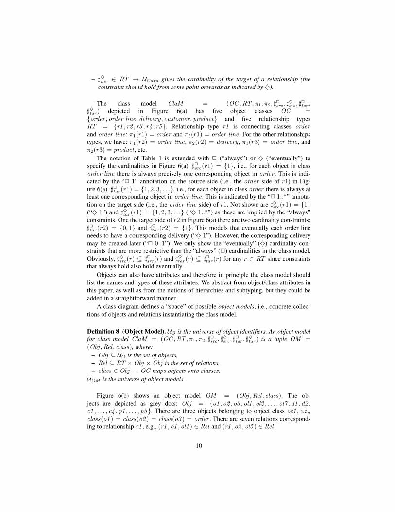
Next to behavior as captured through events, there are also objects that are groupedin classes. Objects may be related and cardinality constraints help to structure depen-dencies. Entity-Relationship (ER) models [6], UML class models [9], and Object-RoleModels (ORM) [10] are examples of notations used for object modeling, often referredto as data modeling. In this paper, we use the simple notation shown in Figure 6(a) tospecify class models. The notation can be viewed as a subset of such mainstream no-tations. The only particular feature is that cardinality constraints can be tagged as “al-ways” (2) or “eventually” (♦). For example, for every order order line there is always
8

at most one delivery (2 0..1) and eventually (i.e., from some point in time onwards)there should be a corresponding delivery(♦ 1).
r1 r2
r3
r1r2
r3
(a) class model
(b) object model
1
1 1
1
1
1
1
1..* 1..* 1
1
* * *
0..1
r4 r5
order lineorder delivery
product
customerr4
r5
order lineorder delivery
product
customer
ol1
ol2
ol3
ol4
ol5
ol6
ol7
o1
o2
o3
d1
d2
p1
p2p3p4
p5
c1
c2c3
c4r5
r4 r4
r1
r1
r1
r1
r1
r2
r2
r2
r2
r3r3
r3 r3r3r3
r1
Fig. 6. Example of a class model and corresponding object model.
Definition 7 (Class Model). A class model is a tuple ClaM = (OC ,RT , π1, π2, ]2src ,
]♦src , ]2tar , ]
♦tar ),where
– OC is a set of object classes,– RT is a set of relationship types (OC ∩ RT = ∅),– π1 ∈ RT → OC gives the source of a relationship,– π2 ∈ RT → OC gives the target of a relationship,– ]2src ∈ RT → UCard gives the cardinality of the source of a relationship (the
constraint should hold at any point in time as indicated by 2),– ]♦src ∈ RT → UCard gives the cardinality of the source of a relationship (the
constraint should hold from some point onwards as indicated by ♦),– ]2tar ∈ RT → UCard gives the cardinality of the target of a relationship (the
constraint should hold at any point in time as indicated by 2), and
9
– ]♦tar ∈ RT → UCard gives the cardinality of the target of a relationship (theconstraint should hold from some point onwards as indicated by ♦).
The class model ClaM = (OC ,RT , π1, π2, ]2src , ]
♦src , ]
2tar ,
]♦tar ) depicted in Figure 6(a) has five object classes OC ={order , order line, delivery , customer , product} and five relationship typesRT = {r1 , r2 , r3 , r4 , r5}. Relationship type r1 is connecting classes orderand order line: π1(r1) = order and π2(r1) = order line . For the other relationshipstypes, we have: π1(r2) = order line , π2(r2) = delivery , π1(r3) = order line , andπ2(r3) = product , etc.
The notation of Table 1 is extended with 2 (“always”) or ♦ (“eventually”) tospecify the cardinalities in Figure 6(a). ]2src(r1) = {1}, i.e., for each object in classorder line there is always precisely one corresponding object in order . This is indi-cated by the “2 1” annotation on the source side (i.e., the order side of r1) in Fig-ure 6(a). ]2tar (r1) = {1, 2, 3, . . .}, i.e., for each object in class order there is always atleast one corresponding object in order line . This is indicated by the “2 1..∗” annota-tion on the target side (i.e., the order line side) of r1. Not shown are ]♦src(r1) = {1}(“♦ 1”) and ]♦tar (r1) = {1, 2, 3, . . .} (“♦ 1..∗”) as these are implied by the “always”constraints. One the target side of r2 in Figure 6(a) there are two cardinality constraints:]2tar (r2) = {0, 1} and ]♦tar (r2) = {1}. This models that eventually each order lineneeds to have a corresponding delivery (“♦ 1”). However, the corresponding deliverymay be created later (“2 0..1”). We only show the “eventually” (♦) cardinality con-straints that are more restrictive than the “always” (2) cardinalities in the class model.Obviously, ]♦src(r) ⊆ ]2src(r) and ]♦tar (r) ⊆ ]2tar (r) for any r ∈ RT since constraintsthat always hold also hold eventually.
Objects can also have attributes and therefore in principle the class model shouldlist the names and types of these attributes. We abstract from object/class attributes inthis paper, as well as from the notions of hierarchies and subtyping, but they could beadded in a straightforward manner.
A class diagram defines a “space” of possible object models, i.e., concrete collec-tions of objects and relations instantiating the class model.
Definition 8 (Object Model). UO is the universe of object identifiers. An object modelfor class model ClaM = (OC ,RT , π1, π2, ]
2src , ]
♦src , ]
2tar , ]
♦tar ) is a tuple OM =
(Obj ,Rel , class), where:– Obj ⊆ UO is the set of objects,– Rel ⊆ RT ×Obj ×Obj is the set of relations,– class ∈ Obj → OC maps objects onto classes.UOM is the universe of object models.
Figure 6(b) shows an object model OM = (Obj ,Rel , class). The ob-jects are depicted as grey dots: Obj = {o1 , o2 , o3 , ol1 , ol2 , . . . , ol7 , d1 , d2 ,c1 , . . . , c4 , p1 , . . . , p5}. There are three objects belonging to object class oc1 , i.e.,class(o1 ) = class(o2 ) = class(o3 ) = order . There are seven relations correspond-ing to relationship r1 , e.g., (r1 , o1 , ol1 ) ∈ Rel and (r1 , o2 , ol5 ) ∈ Rel .
10

Note that objects and events are represented by unique identifiers. This allows us torefer to a specific object or event. Even two events or objects with the same propertiesare still distinguishable by their identity.
The cardinalities specified in the class model should be respected by the objectmodel. For example, for each object in class order line there is precisely one corre-sponding object in order according to r1 . A valid object model complies with the“always” (2) cardinalities in the class model. A valid model is also fulfilled is also thepossibly stronger “eventually” (♦) cardinality constraints are satisfied.
Definition 9 (Valid Object Model). Let ClaM = (OC ,RT , π1, π2, ]2src , ]
♦src , ]
2tar ,
]♦tar ) be a class model and OM = (Obj ,Rel , class) ∈ UOM be an object model.OM is valid for ClaM if and only if
– for any (r, o1, o2) ∈ Rel : class(o1) = π1(r) and class(o2) = π2(r),– for any r ∈ RT and o2 ∈ ∂π2(r)(Obj ), we have that 7
|{o1 ∈ Obj | (r, o1, o2) ∈ Rel}| ∈ ]2src(r), and
– for any r ∈ RT and o1 ∈ ∂π1(r)(Obj ), we have that
|{o2 ∈ Obj | (r, o1, o2) ∈ Rel}| ∈ ]2tar (r)
A valid objected model is also fulfilled if the stronger cardinality constraints hold (theseare supposed to hold eventually):
– for any r ∈ RT and o2 ∈ ∂π2(r)(Obj ), we have that
|{o1 ∈ Obj | (r, o1, o2) ∈ Rel}| ∈ ]♦src(r), and
– for any r ∈ RT and o1 ∈ ∂π1(r)(Obj ), we have that
|{o2 ∈ Obj | (r, o1, o2) ∈ Rel}| ∈ ]♦tar (r)
The object model in Figure 6(b) is indeed valid. If we would remove relation(r1 , o1 , ol1 ), the model would no longer be valid (because an order line should al-ways have a corresponding order). Adding a relation (r1 , o2 , ol1 ) would also destroyvalidity. Both changes would violate the “2 1” constraint on the source side of r1. Theobject model in Figure 6(b) is not fulfilled because the “♦ 1” constraint on the targetside of r2 does not hold. Order lines ol2 and ol4 do not (yet) have a correspondingdelivery. Adding deliveries for these order lines and adding the corresponding relationswould make the model fulfilled.
Definition 9 only formalizes simple cardinality constraints involving a binary rela-tion and abstracting from attribute values. In principle more sophisticated constraintscould be considered: the object model OM is simply checked against a class modelClaM . For example, the Object Constraint Language (OCL) [17] could be used to de-fine more refined constraints.
7 ∂oc(Obj ) = {o ∈ Obj | class(o) = oc} denotes the whole set of objects in class oc.
11

4 Object-Centric Behavioral Constraints
In Section 2, we focused on control-flow modeling and formalized behavioral con-straints without considering the structure of objects. In Section 3, we focused on struc-turing objects and formalized cardinality constraints on object models (i.e., classicaldata modeling). In this section, we combine both perspectives to fully address the chal-lenges described in the introduction.
4.1 Object-Centric Event Logs
First, we formalize the notion of an event log building on the event notion introduced inDefinition 1. An event log is a collection of events that belong together, i.e., they belongto some “process” where many types of objects/instances may interact. Next to scopingthe log, we also relate events to objects. Note that the same event may refer to multipleobjects and one object may be referred to by multiple events.
Definition 10 (Event Log). An event log is a tuple L = (E, act , attr ,EO , om,�),where
– E ⊆ UE is a set of events,– act ∈ E → UA maps events onto activities,– attr ∈ E → (UAttr 6→ UVal) maps events onto a partial function assigning values
to some attributes,– EO ⊆ E × UO relates events to sets of object references,– om ∈ E → UOM maps each event to the object model directly after the event took
place, and– � ⊆ E × E defines a total order on events.
In the context of an event L, each event e is associated with object model OM e =(Obj e,Rele, classe) = om(e). In the remainder, we refer directly to Obj e, Rele, classefor e ∈ E if the context is clear.
o1
e1
o5
o1
e2
o2
o5
o1
o3
e3
o2
o5
o1
o3
e4
o2
o4
o5
o1
o3
e5
o2
o4
o5
Fig. 7. Each event e refers to the object model right after e occurred: OM e =(Obj e,Rele, classe) = om(e).
Figure 7 illustrates the evolution of the object model. After the occurrence of someevent e objects may have been added (we assume monotonicity), and relationships may
12

have been added or removed. Event e may refer to objects through relation EO andthese objects need to exist, i.e., for all (e, o) ∈ EO : o ∈ Obj e. We assume that objectscannot be removed at a later stage to avoid referencing non-existent objects. Objectscan be marked as deleted but cannot be removed (e.g, by using an attribute or relation).
The event log provides a snapshot of the object model after each event. This triggersthe question: Can the object model be changed in-between two subsequent events? Ifno such changes are possible, then the object model before an event is the same as theobject model after the previous event. If we would like to allow for updates in-betweenevents, then these could be recorded in the log. Events referring to some artificial activ-ity update could be added to signal the updated object model. We could also explicitlyadd a snapshot of the object model just before each event. In the remainder, we onlyconsider the snapshot OM e after each event e ∈ E.
Note that Definition 10 calls for event logs different from the standard XES format.XES (www.xes-standard.org), which is supported by the majority of processmining tools, assumes a case notion (i.e., each event refers to a process instance) anddoes not keep track of object models.
4.2 OCBC Models
Next, we define Object-Centric Behavioral Constraint (OCBC) models. Through acombination of control-flow modeling and data/object modeling, we relate behaviorand structure. The BC models from Section 2 are connected to the class models ofSection 3 to provide the integration needed.
t1
pay
ticket
1..*
0..1
1
t2
p1
t1 t2
t3
p23
t1 t2
t3
p3
payment eventthat refers to tickets
t2 and t3
object model directly afterthe payment event (having
three ticket objects)
fragment of larger OCBC model
activity
object class
every payment refers to one or
more tickets
every ticket always refers to at most one payment
eventually everyticket refers to precisely
one payment
t4
Fig. 8. Illustrating cardinality constraints ]2A, ]♦A , and ]OC .
A key ingredient is that events and objects are related as illustrated in Figure 8.Payment activity p1 refers to ticket t1 , activity p23 refers to tickets t2 and t3 , andactivity p3 refers to ticket t4 . Figure 8 shows three example constraints: “2 0..1” (everyticket always refers to at most one payment), “♦ 1” (eventually every ticket refers toprecisely one payment), and “1..∗” (every payment refers to one or more tickets).
13

Definition 11 (Object-Centric Behavioral Constraint Model). Anobject-centric behavioral constraint model is a tuple OCBCM =(BCM ,ClaM ,AOC , ]2A, ]
♦A, ]OC , crel), where
– BCM = (A,C, πref , πtar , type) is a BC model (Definition 5),– ClaM = (OC ,RT , π1, π2, ]
2src , ]
♦src , ]
2tar , ]
♦tar ) is a class model (Definition 7),
– A, C, OC and RT are pairwise disjoint (no name clashes),– AOC ⊆ A×OC is a set of relations between activities and object classes,– ]2A ∈ AOC → UCard gives the cardinality of the source of a relation linking an
activity and an object class (activity side, the constraint should hold at any point intime as indicated by 2),
– ]♦A ∈ AOC → UCard gives the cardinality of the source of a relation linking anactivity and an object class (activity side, the constraint should hold from somepoint onwards as indicated by ♦),
– ]OC ∈ AOC → UCard gives the cardinality of the target of a relation linking anactivity and an object class (object-class side), and
– crel ∈ C → OC ∪RT is the constraint relation satisfying the following conditionsfor each c ∈ C:• {(πref (c), oc), (πtar (c), oc)} ⊆ AOC if crel(c) = oc ∈ OC , and• {(πref (c), π1(r)), (πtar (c), π2(r))} ⊆ AOC or {(πref (c), π2(r)), (πtar (c),π1(r))} ⊆ AOC if crel(c) = r ∈ RT .
a1 a2 a3
oc2oc1 oc31 1..* 1..2 0..*
1
1
1..*
1 1..*
0..10..*
1
1
r1 r2
c1 c2
activity
constraint
object class
each a1 event refers to precisely
one oc1 object
relationship between activities
and classes
indicating the reference event
constraint relation(used to determine target events related
to the reference event)
0..*
each oc2 object refers to at least one a1 activity
1 1..*
Fig. 9. An example model illustrating the main ingredients of an OCBC model.
An Object-Centric Behavioral Constraint model (OCBC model) includes a behav-ioral constraint model (to model behavior) and a class model (to model objects/data).These are related through relation AOC and functions ]2A, ]♦A, ]OC , and crel . We useFigure 9 to clarify these concepts.
14

AOC relates activities and object classes. In Figure 9, AOC = {(a1 , oc1 ),(a1 , oc2 ), (a2 , oc2 ), (a3 , oc2 ), (a3 , oc3 )}. For example, a1 may potentially refer tooc1 and oc2 objects, but not to oc3 objects because (a1 , oc3 ) 6∈ AOC . Recall thatin an event log L there is a many-to-many relationship between events and objects(EO ⊆ E × UO) constrained by AOC .
Functions ]2A, ]♦A, and ]OC define possible cardinalities, similar to cardinality con-straints in a class model. Functions ]2A and ]♦A define how many events there need to befor each object. Since the object model is evolving, there are two types of constraints:constraints that should hold at any point in time from the moment the object exists (]2A)and constraints that should eventually hold ]♦A. Function ]OC defines how many objectsthere need to be for each event when the event occurs (specified by EO).
As indicated by the “2 1” annotation on the a1 -side of the line connecting ac-tivity a1 and object class oc1 , there is precisely one a1 event for each oc1 object(from the moment it exists): ]2A(a1 , oc1 ) = {1}. As indicated by the “♦ 1..∗” onthe a1 -side of the line connecting activity a1 and object class oc2 , we have that]♦A(a1 , oc2 ) = {1, 2, . . .}. This means that eventually each oc2 object refers to at leastone a1 activity. Note that an oc2 object does not need to have a corresponding a1 eventwhen it is created. However, adding a new oc2 object implies the occurrence of at leastone corresponding a1 event to satisfy the cardinality constraint “♦ 1..∗”, i.e., an obli-gation is created. If the annotation “2 1..∗” would have been used (instead of “♦ 1..∗”),then the creation of any oc2 object needs to coincide with a corresponding a1 event,because the cardinality constraints should always hold (2) and not just eventually (♦).
As indicated by the “1” annotation on the oc2 -side of the line connecting activitya1 and object class oc2 , we then have that ]OC (a1 , oc2 ) = {1}. This means that eacha1 activity refers to precisely one oc2 object.
Let’s now consider relation (a2 , oc2 ) ∈ AOC . There should be at most one a2event for each oc2 object from the moment it exists: ]2A(a2 , oc2 ) = {0, 1}. Eventu-ally there should be precisely one a2 event for each oc2 object: ]♦A(a2 , oc2 ) = {1}.]OC (a2 , oc2 ) = {1, 2, . . .} indicates that each a2 event refers to at least one oc2 ob-ject.
Annotations of the type “♦ 0..∗” and “2 0..∗” are omitted from the diagram becausethese impose no constraints. Also implied constraints can be left out, e.g., “2 1..∗”implies “♦ 1..∗”.
Function crel defines the scope of each constraint thereby relating reference eventsto selected target events. crel(c) specifies how events need to be correlated when eval-uating constraint c. This is needed because we do not assume a fixed case notion anddifferent entities may interact. As illustrated by Figure 10 we basically consider twotypes of constraints. In both cases we navigate through the object model to find tar-get events for a given reference event. Figures 11 and 12 illustrate how to locate targetevents. For each reference event we need the set of all target events in order to checkthe cardinality constraint.
If crel(c) = oc ∈ OC , then the behavioral constraint is based on object class oc. InFigure 9, crel(c2 ) = oc2 . This means that the target events for constraint c2 need tobe related to the reference events through objects of class oc2 . Let eref be the reference
15

a1 a2
oc
ca1 a2
oc1 oc2r
c
(a) the reference event and target events are related through common objects
(b) the reference event and target events are related through relations in the object model
Fig. 10. Two types of constraint relations: (a) crel(c) = oc ∈ OC , i.e., the target events arerelated to the reference event through shared objects of the class oc, (b) crel(c) = r ∈ RT , i.e.,the target events are related to the reference event through relations of type r (in any direction).
a1 a2
oc
c
a1
e4e3
a2
e8e5
e10
e2
o1
o7
oc
e1
e6e9
e7
o5
o4
o6
o2
o3
e6, e7, and e9 are the target events corresponding to
reference event e1
assume e1 is the reference event we
are interested in
reference events are related to target events through the object
model: a1 events are related to oc objects that are related to a2 events
Fig. 11. Given a reference event for a constraint with crel(c) = oc ∈ OC we navigate to thetarget events through shared object references.
event for constraint c2 . eref refers to 1 or more oc2 objects. The target events of ereffor c2 are those a3 events referring to one of these objects.
If crel(c) = r ∈ RT , then the target events are related to the reference event throughrelations of type r in the object model. Relation r can be traversed in both directions.In Figure 9, crel(c1 ) = r1 indicating that reference events are related to target eventsthrough relationship r1 . Let eref be the reference a1 event for constraint c1 . eref refersto oc1 objects that are related to oc2 objects through r1 relations. The target events oferef for c1 are those a2 events referring to one of these oc2 objects.
We have now introduced all the modeling elements used in Figure 2. Note that cre-ate order activities are related to pick item activities through the relationship connectingclass order with class order line.
16

a1 a2
oc1 oc2r
c
a1 a2
oc1 oc2r
e4e3
e8e5
e10
e2
e1
e6e9
e7
o1
o2
o309
o10
o7
o8
o4
o5
o6
assume e1 is the reference event we
are interested in
e6, e7, and e9 are the target events corresponding to
reference event e1
reference events are related to target events through the object model: a1 events are
related to oc1 objects that are related to oc2 objects (via r) that are related to a2 events
Fig. 12. Given a reference event for a constraint with crel(c) = r ∈ RT we navigate to the targetevents through relation r in the object model.
4.3 Discussion
The graphical notation introduced (e.g., like in Figure 2) fully defines an OCBC model.To illustrate this let us consider a completely different example.
Figure 13 models a hiring process. An organization may create a position. Peoplecan apply for such a position, but need to register first. Applications for a position areonly considered in the period between opening the position and closing the applicationprocess for the position. An application may be followed by at most five referencechecks and at most two interviews. In the end one person is selected and subsequentlyhired for the position.
There are four object classes in the OCBC model: person, application, position,and employee. The cardinality constraints in Figure 13 show that: each application al-ways refers to precisely one person and one position, each person eventually applies forsome position, for every position there will eventually be an application, each employeerefers to precisely one application and position, each application refers to at most oneemployee, and each position will eventually refer to one employee.
There is a one-to-one correspondence between registrations (activity register) andpersons (class person). Activities apply, check reference, and interview each refer to theclass application. Activity apply creates one new application object. Activities openpos., check close pos., and select each refer to the class position. Activity open pos.creates one new position object. There is also a one-to-one correspondence betweenhirings (activity hire) and employees (class employee).
Let us now consider the constraints in more detail:– Constraint c1 specifies that every reference check should be preceded by precisely
one corresponding application (unary-precedence constraint).– Constraint c2 specifies that every interview should be preceded by precisely one
corresponding application (unary-precedence).
17

register
applicationperson position
1
employee
1
1
1
1..*
0..1
r1 r2
r3
11..*
1
1
r4
open pos.
close pos.
selecthire
apply
check reference
interview
1
1
1
0..2
1
1
1
1
1
1
1
0..5
11
c1
c2
c3
c4
c5
c6
c7 c8
Fig. 13. An OCBC model modeling a hiring process.
– Constraint c3 combines a unary-response and a unary-precedence constraint statingthat the opening a a position should be followed by the closing of the applicationprocess and the closing should be preceded by the opening of the position.
– Constraint c4 also combines a unary-response and a unary-precedence constraintstating that the two activities are executed in sequence.
– Constraint c5 specifies that applications for a position need to be preceded by theopening of that position.
– Constraint c6 specifies that after closing a position there should not be any newapplications for this position (non-response constraint).
– Constraint c7 specifies that every hire needs to be preceded by at least one interviewwith the candidate applying for the position (precedence constraint).
– Constraint c8 again combines a unary-response and a unary-precedence constraintstating that the two activities are executed in sequence.
It is important to note that the constraints are based on the object model and thatthere is not a single instance notion. To illustrate this consider the BPMN model in Fig-ure 14 which models the lifecycles of persons, positions, applications, and employeesin separate diagrams. The BPMN model looks very simple, but fails to capture depen-dencies between the different entities. Consider for example constraints c5, c6, c7, andc8 in the OCBC model of Figure 13. The BPMN model does not indicate that thereis a one to many relationship between positions and applications, and does not showthat one can only apply if the corresponding position is opened but not yet closed. TheBPMN model does not indicate that only one person is hired per position and that theperson to be hired should have registered, applied, and had at least one interview. TheBPMN model does not indicate that employees are hired after the completion of the
18

selection process. Note that the same person could apply for multiple positions andmany people may apply for the same position. Obviously this cannot be captured usinga single process instance (case) notion.
application
position
open pos. close pos. select
apply
check reference
interview
employee
hire
person
register
Fig. 14. An attempt to capture the OCBC model of Figure 13 in terms of four BPMN models. Therelations with the overall data model and interactions between the different entities are no longervisible. For example, insights like “one can only apply if the corresponding position is openedbut not yet closed” and “only people that had an interview can be hired” get lost.
Comparing Figure 13 and Figure 14 reveals that modeling the lifecycles of enti-ties separately, like in artifact-centric approaches, is not sufficient to capture the realprocess. The individual lifecycles are simple, but fail to reveal the interplay betweenpersons, positions, applications, and employees.
It is essential to understand that the scoping of events considered in a constraintis done through the object model. This provides a tight integration between behaviorand structure. Moreover, the approach is much more general and more expressive thanclassical approaches where events are correlated through cases. Normally, process mod-els (both procedural and declarative) describe the lifecycle of a process instance (i.e.,case) in isolation. This implies that events are partitioned based on case identifiers anddifferent cases cannot share events. Hence, one-to-many and many-to-many relation-ships cannot be modeled (without putting instances in separate subprocesses, artifactsor proclets). In fact, more complicated forms of interaction cannot be handled.
Note that traditional single-instance modeling approaches can still be mimickedby using an object model having one object class case and crel(c) = case for eachconstraint c. Figure 15 sketches this situation and illustrates that the classical view onprocess behavior is every limiting, since complex relationships cannot be captured, andthe link to data/object models is missing.
5 Conformance Checking Using OCBC Models
Given an event log, an object model, and an object-centric behavioral constraint model,we want to check whether reality (in the form of an event log L and an object model
19

a1 a2 a3
occase1
1
0..* 0..*
c1 c2
0..*
1
Fig. 15. An OCBC model mimicking the classical situation where behavior needs to be straight-jacketed in isolated process instances (i.e., cases).
OM ) conforms to the model OCBCM . We identify nine types of possible conformanceproblems. Most of these problems are not captured by existing conformance checkingapproaches [2,8,13,18].
First, we implicitly provide operational semantics for OCBC models by defining aconformance relation between event log and model.
Definition 12 (Conformance). Let OCBCM = (BCM ,ClaM ,AOC , ]2A,]♦A, ]OC , crel) be an OCBC model, with BCM = (A,C, πref , πtar , type) andClaM = (OC ,RT , π1, π2, ]
2src , ]
♦src , ]
2tar , ]
♦tar ). Let L = (E, act , attr ,EO , om,�)
be an event log.Event log L conforms to the object-centric behavioral constraint model OCBCM
if and only if:
– There are no Type I problems (validity of object models): for any e ∈ E: objectmodel OM e = (Obj e,Rele, classe) is valid for ClaM (this includes checking the2-cardinality constraints that should always hold as stated in Definition 9),
– There are no Type II problems (fulfilment): there is an event ef ∈ �e(E) suchthat for any e′ ∈ �ef(E): OM e = (Obj e,Rele, classe) is also fulfilled (this in-volves checking the ♦-cardinality constraints that should eventually hold as statedin Definition 9),
– There are no Type III problems (monotonicity): for any e1, e2 ∈ E such thate1 ≺ e2: Obj e1 ⊆ Obj e2 and classe1 ⊆ classe2 (objects do not disappear orchange class in-between events).
– There are no Type IV problems (activity existence): {act(e) | e ∈ E} ⊆ A (allactivities referred to by events exist in the behavioral model),
– There are no Type V problems (object existence): for all (e, o) ∈ EO: o ∈ Obj e(all objects referred to by an event exist in the object model when the event occurs),8
– There are no Type VI problems (proper classes): {(act(e), classe(o)) | (e, o) ∈EO} ⊆ AOC (events do not refer to objects of unrelated classes).
– There are no Type VII problems (right number of events per object): for any(a, oc) ∈ AOC , e ∈ E, and o ∈ ∂oc(Obj e):
8 Combined with the earlier requirement, this implies that these objects also exist in later objectmodels.
20

• for any e′ ∈ �e(E): |{e′′ ∈ ∂a(�e′(E)) | (e′′, o) ∈ EO}| ∈ ]2A(a, oc) (eachobject o of class oc has the required number of corresponding a events),
• there exists a future event ef ∈�e(E) such that for any e′ ∈�ef(E): |{e′′ ∈∂a(�e′(E)) | (e′′, o) ∈ EO}| ∈ ]♦A(a, oc) (each object o of class oc eventuallyhas the required number of corresponding a events),
– There are no Type VIII problems (right number of objects per event): for any(a, oc) ∈ AOC , e ∈ ∂a(E): |{o ∈ ∂oc(Obj e) | (e, o) ∈ EO}| ∈ ]OC (a, oc)(each event e corresponding to activity a has the required number of correspondingobjects of class oc).
– There are no Type IX problems (behavioral constraints are respected): for eachconstraint c ∈ C and reference event eref ∈ ∂πref (c)(E): there exists a future eventef ∈ E such that for any e′ ∈ �ef(E): (|�eref (Etar )|, |�eref (Etar )|) ∈ type(c)where• Etar = {etar ∈ ∂πtar (c)(E) | ∃o∈∂oc(Obje′ )
{(eref , o), (etar , o)} ⊆ EO} ifcrel(c) = oc ∈ OC ,
• Etar = {etar ∈ ∂πtar (c)(E) | ∃o1,o2∈Obje′ ({(r, o1, o2), (r, o2, o1)} ∩ Rele′ 6=∅) ∧ {(eref , o1), (etar , o2)} ⊆ EO} if crel(c) = r ∈ RT .
Any event log L that exhibits none of the nine problems mentioned is conformingto OCBCM . Therefore, one can argue that Definition 12 provides operational seman-tics to OCBC models. However, the ultimate goal is not to provide semantics, but tocheck conformance and provide useful diagnostics. By checking conformance usingDefinition 12, the following four broad classes of problems may be uncovered:
– Type I, II, and III problems are related to the object models attached to the events(e.g., object models violating cardinality constraints).
– Type IV, V, and VI problems are caused by events referring to things that do notexist (e.g., non-existing activities or objects).
– Type VII and VIII problems refer to violations of cardinality constraints betweenactivities and object classes.
– Type IX problems refer to violations of the behavioral constraints (e.g., a violationof a response or precedence constraint).The first two categories (Type I-VI problems) types are more of a bookkeeping
nature and relatively easy to understand. The two categories (VII, VIII, IX problems)are related to the more subtle interplay between activities, objects, relations, and thebehavior over time. These are more interesting, but also quite difficult to understand.Therefore, we elaborate on Type VII, VIII, IX problems.
Figure 16 shows a situation with problems of Type VII and Type VIII. Object t3has twee corresponding payment events (p1 and p2), thus violating the “2 0..1” an-notation. Object t5 has no corresponding payment events, thus violating the “♦ 1”annotation (assuming there is no corresponding payment in the future). Event p3 has nocorresponding payment events, thus violating the “1..∗” annotation. Note that the objectmodel is evolving while the process is executed. This is not shown in Figure 16, i.e., thediagram should be viewed as a snapshot of the process after four payment events.
Figure 17 shows a situation with problems of Type IX. All a2 events should haveprecisely one preceding a1 event that is related through relation r. Note that in principlethe object model is evolving, but let us assume that all seven events have the object
21

activity pay (events)
p3
p1
t1
t2
t3
pay
ticket
1..*
0..1
1
class ticket (objects)
p2 p4
t4
t5
there cannot be a payment event without any corresponding ticket (Type VIII problem)
there cannot be a ticket with two related payment events (Type VII problem)
eventually every ticket needs to have a corresponding payment event (Type VII problem)
Fig. 16. An illustration of Type VII and VIII problems (all related to violations of cardinalityconstraints between activities and object classes).
a1 a2
oc1 oc2r
c
a1
oc1 oc2
r
for simplicity we assume that the object model does not
change in this example
1
1
1
1
1 1..*
a2
time
e7
e1
o1
o2
o3
o4
o6
o5 o7
o8
e2 e5 e6
e4
e3
reference event e6 has no target events and therefore the precedence constraint is violated
reference event e3 has one target event (e4) but this target event is executed after the reference event and therefore the precedence constraint is violated
Fig. 17. An illustration of Type IX problems. The a1 and a2 events are executed in the order in-dicated (from left to right). The object model is assumed to remain invariant during the executionof the events (to simplify the explanation). Constraint c is violated for two of the five referenceevents: both e3 and e6 have no corresponding a1 event that occurred earlier.
model shown at the lower part of Figure 17. As stated in Definition 12, there should bean event ef after which the constraint holds for any event e′ and corresponding objectmodel OM e′ . Note that the two cases in the last condition of Definition 12 correspondto the two constraint relations depicted in Figure 10. For each reference event eref , thecorresponding set of target events Etar is determined by following the links throughthe object model. For each eref , the cardinalities are checked: (|�eref (Etar )|, |�eref(Etar )|) ∈ type(c). Hence, it is possible to identify the reference events for which theconstraint is violated.
For the situation depicted in Figure 17: type(c) = {(before, after) ∈ IN × IN |before = 1}, i.e., there should be precisely one target (a1) event preceding each refer-ence (a2) event related through r. Consider e2 = eref as reference event: Etar = {e1}and target event e1 occurs indeed before e2. Hence, no problem is discovered for e2.Next we consider e3 = eref as reference event: Etar = {e4}, but target event e4 occurs
22

after e3. Hence, e3 has no preceding target event signaling a violation of constraint cfor reference event e3. If we consider e5 = eref as reference event, we find no prob-lem because Etar = {e1} and target event e1 occurs indeed before e5. If we considere6 = eref as reference event, we find again a problem because Etar = ∅, so no targetevent occurs before e6. If we consider e7 = eref as reference event, we find no problembecause Etar = {e4} and target event e4 occurs before after e7. Hence, we find tworeference event (e3 and e6) for which constraint c in Figure 17 does not hold.
Definition 12 not only provides operational semantics for the graphical notation in-troduced in this paper, but also characterizes a wide range of conformance problems.Following the classification of problems used in Definition 12, we mention some pos-sible diagnostics:
1. Diagnostics for Type I problems (validity of object models): Highlight the 2-cardinality constraints that make the object model invalid.
2. Diagnostics for Type II problems (fulfilment): Highlight the ♦-cardinality con-straints that do not hold at the end of the log.
3. Diagnostics for Type III problems (monotonicity): Report objects that disappearor change class over time.
4. Diagnostics for Type IV problems (activity existence): List the activities appear-ing in the log and not in the model and highlight the corresponding events in theevent log.
5. Diagnostics for Type V problems (object existence): Highlight all references tonon-existing objects.
6. Diagnostics for Type VI problems (proper classes): Highlight the events thatrefer to classes they should not refer to. This can also be shown at the model level,e.g., counting how many times an event corresponding to activity a incorrectlyrefers to class oc.
7. Diagnostics for Type VII problems (right number of events per object): High-light the (a, oc) connection if objects in oc do not (eventually/always) have therequired number of a events. One can count the number of violations and annotatethe connections. These violations can also be shown in the event log.
8. Diagnostics for Type VIII problems (right number of objects per event): High-light the (a, oc) connection if a events do not refer to the specified number ofobjects in class oc. One can count the number of violations and annotate the con-nections. The corresponding events can also be highlighted in the event log.
9. Diagnostics for Type IX problems (behavioral constraints are respected):Highlight the constraints that are violated. Per constraint one can count the numberof reference events for which the constraint is violated. These reference events canalso be highlighted in the event log.
The types diagnostics and checks needed are very different from existing confor-mance checking approaches. Most of the conformance checking approaches [2,8,18]only consider control-flow and are unable to uncover the above problems. Recently,conformance checking approaches based on alignments have been extended to alsocheck conformance with respect to the data perspective [13]. However, these do notconsider a data model and focus on one instance at a time.
23

Constraints may be temporarily violated while the process is running [4,15]. Con-sider for example a response constraint involving activities a and b: after executingactivity a the constraint is temporarily violated until activity b is executed. This notionexists in any modeling language where process instances need to terminate and is notlimited to declarative languages. Interestingly, the addition of an object may also cre-ate temporarily violated and permanently violated constraints. Consider Figure 2 again.Adding an order line object without creating a corresponding order results in a per-manent violation. However, adding an order line while also creating an order creates acascade of obligations: the obligation to have a delivery object, the obligation to have apick item event, and the obligation to have a wrap item event. The corresponding three“♦ 1” cardinalities are temporarily violated, but can still be satisfied in the future. Im-plicitly, there is also the obligation to have a corresponding deliver items event in thefuture.
Interestingly, conformance over OCBC models can be checked very efficiently. Inparticular, each of the requirements in Definition 12 can be formalized as a boolean,SQL-like query over the input log. The final result is obtained by conjoining all theobtained answers. This means that the data complexity of conformance checking9 isin AC0. Recall that AC0 is strictly contained in LOGSPACE, and corresponds to thecomplexity of SQL query answering over a relational database, measured in the size ofthe database only.
6 Conclusion
In this paper, we proposed Object-Centric Behavioral Constraint (OCBC) models as anintegrated approach that merges declarative process modeling and data modeling. Car-dinality constraints are used to specify structure and behavior in a single diagram. Inexisting approaches, there is often a complete separation between data/structure (e.g.,a class model) and behavior (e.g., BPMN, EPCs, or Petri nets). In OCBC models, dif-ferent types of instances can interact in a fine-grained manner and the constraints in theclass model guide behavior.
OCBC models are particularly suitable for conformance checking. Many deviationscan only be detected by considering multiple instances and constraints in the classmodel. In this paper, we identified nine types of conformance problems that can bedetected using OCBC models.
The integration of data and control-flow constraints gives raise to sophisticated pat-terns that cannot be captured in contemporary process modeling approaches. In thislight, we want to identify typical behavioral (anti-)patterns that involve multiple in-stances or interaction between structure and behavior. Figure 18 shows an examplepattern. Along this line, we plan to study the effect of introducing subtyping in the datamodel, a constraint present in all data modeling approaches. The interplay between be-havioral constraints and subtyping gives rise to other interesting behavioral patterns. Forexample, implicit choices may be introduced through subtyping. Consider a responseconstraint pointing to a payment class with two subclasses credit card payment and cash
9 That is, the complexity measured in the size of the log only, assuming that the OCBC modelis fixed.
24

end parent end child
childparent1 1..*
1
1 1
1
r1
c1
start parent1
1
start childc2
c3
c4
1
1
Fig. 18. Example pattern. After start-ing the parent, all k children (as de-fined by r1) need to start. After all kchildren ended, the parent ends.
payment. Whenever the response constraint is activated and a payment is expected, suchan obligation can be fulfilled by either paying via cash or credit card.
Finally, we also want to investigate how the notions of consistency and constraintconflict/redundancy, well-known in the context of Declare [4], and the correspondingnotions of consistency and class consistency, well-known in data models [5], can besuitably reconstructed and combined in our setting. In this respect, we are currentlystudying how to formalize OCBC models using temporal description logics, on theone hand to obtain a logic-based semantics for our approach, and on the other handto derive techniques and decidability/complexity insights on consistency checking andother reasoning tasks.
References
1. W. Aalst. Process Mining: Discovery, Conformance and Enhancement of Business Processes- 2nd Edition. Springer, 2016.
2. W. Aalst, A. Adriansyah, and B. Dongen. Replaying History on Process Models for Confor-mance Checking and Performance Analysis. WIREs Data Mining and Knowledge Discovery,2(2), 2012.
3. W. Aalst, P. Barthelmess, C. Ellis, and J. Wainer. Proclets: A Framework for LightweightInteracting Workflow Processes. International Journal of Cooperative Information Systems,10(4), 2001.
4. W. Aalst, M. Pesic, and H. Schonenberg. Declarative Workflows: Balancing Between Flexi-bility and Support. Computer Science - Research and Development, 23(2), 2009.
5. D. Berardi, D. Calvanese, and G. De Giacomo. Reasoning on UML class diagrams. Artif.Intell., 168(1-2), 2005.
6. P. Chen. The Entity-Relationship Model - Toward a Unified View of Data. ACM Transactionon Database Systems, 1(1), 1976.
7. D. Cohn and R. Hull. Business Artifacts: A Data-centric Approach to Modeling BusinessOperations and Processes. IEEE Data Engineering Bulletin, 32(3), 2009.
8. D. Fahland, M. Leoni, B. Dongen, and W. Aalst. Behavioral Conformance of Artifact-CentricProcess Models. In Business Information Systems (BIS 2011), volume 87 of LNBIP. Springer,2011.
9. O. M. Group. OMG Unified Modeling Language 2.5. OMG, 2013.10. T. Halpin and T. Morgan. Information Modeling and Relational Databases. Morgan Kauf-
mann Publishers Inc., San Francisco, CA, USA, 2008.
25

11. K. Hee. Information System Engineering: a Formal Approach. Cambridge University Press,1994.
12. R. Hull et al. Business Artifacts with Guard-Stage-Milestone Lifecycles: Managing ArtifactInteractions with Conditions and Events. In International Conference on Distributed Event-Based Systems (DEBS 2011). ACM, 2011.
13. M. Leoni, W. Aalst, and B. Dongen. Data- and Resource-Aware Conformance Checking ofBusiness Processes. In Business Information Systems (BIS 2012), volume 117 of LNBIP.Springer, 2012.
14. N. Lohmann. Compliance by Design for Artifact-Centric Business Processes. In BusinessProcess Management (BPM 2011), volume 6896 of LNCS. Springer, 2011.
15. F. Maggi, M. Montali, M. Westergaard, and W. Aalst. Monitoring Business Constraints withLinear Temporal Logic: An Approach Based on Colored Automata. In BPM 2011, volume6896 of LNCS. Springer, 2011.
16. A. Nigam and N. Caswell. Business artifacts: An Approach to Operational Specification.IBM Systems Journal, 42(3), 2003.
17. OMG. Object Constraint Language - version 2.4, 2014. Available at: http://www.omg.org/spec/OCL/2.4/PDF.
18. A. Rozinat and W. Aalst. Conformance Checking of Processes Based on Monitoring RealBehavior. Information Systems, 33(1), 2008.
26