observatory automation project
TRANSCRIPT
OAP Dome drive PDR Appendix I
Page I1 of I31
Observatory Automation Project Preliminary Design Review Electric Dome Drive System Steven Bauman
Contributors: Sarah Gajadhar, Grant Matsushige, Ivan Look, Derrick Salmon, Ralph Taroma, Larry Roberts, Casey Elizares, Tyson Arruda, William Cruise, Tom Vermeulen, Jim Thomas, Karun Thanjavur Version 2.0 April 6, 2010
1. Overview Research into the existing hydraulic dome drive system for OAP purposes has highlighted the obsolescence of the current system and prompted the exploration of options for upgrading it. OAP requires that the dome drive system be controlled and monitored remotely. The existing system can be remotely controlled via the telescope control system (TCS) if the hydraulic pumps on the first floor are turned on, however turning them on is currently a manual step. Also, information on the temperatures, pressures, and flows in the system are only available on manual gauges in the 1st floor machinery room and the 4th floor control room. The cost of additional instrumentation for the existing system prompted feasibility studies for upgrading to either a more modern hydraulic drive system, or to an electric drive system. After the feasibility study and conceptual design reviews of these options, the decision was made to pursue the electric drive system upgrade. Benefits of the new electric drive system are: reduced power consumption, reduced maintenance and repair costs, eliminated hydraulic leaks (safety and environmental consequences), and reduced manpower resources. 2. Scope
This document proposes a design solution to operate the Dome system with electronic drive units controlled remotely under the guidelines provided by the OAP project. This document will outline the requirements for the system, document the existing system, discuss design alternatives, and detail the preliminary system design, interfaces, safety considerations, estimated costs and resources. 3. Requirements
3.1. A Dome Drive Electric Upgrade Requirements document has been drafted to encompass specifications and goals of the upgrade. This review will highlight additional requirements for the upgrade. And the last draft of the requirements document will be finalized after the PDR. • The requirements document can be found:
o https://info.cfht.hawaii.edu/display/OPR/Dome+Drive+System+Upgrade+Requirements
Dome drive requirements needed for OAP a) Remote Dome drive Operation The Dome drive must be capable of being
operated in a “safe” reliable manner from Waimea. b) Remote monitoring and status The electronic drive system shall provide
necessary status and system information.
OAP Dome drive PDR Appendix I
Page I2 of I31
c) Manual Control The drive system control panel must allow local control of the drive system.
d) Preventative Maintenance The dome drive system shall provide access to all serviceable components and minimize the need for scheduled maintenance.
e) Improved Reliability The new electronic dome drive system should increase the reliability and minimize repairs.
f) Safe Interlocking The dome drive system shall provide safety interlocking to prevent unauthorized remote control of the drive system. It shall protect personal and other critical systems when/if other systems shutdown or malfunction.
4. Current System Design 4.1. The existing hydraulic dome drive system consists of three drive units positioned
120˚apart around the track on the 5th floor, which supports the telescope building dome rotation. The central hydraulic unit on the first floor supplies the necessary flow at the system pressure 1800 PSI at the pumps and 1775 PSI @ the 4th floor control room.
4.2. For a detailed memo discussing how the existing hydraulic dome drive system functions please see the document referenced below entitled “15-03 Dome Drive Hydraulics General Function”: • https://info.cfht.hawaii.edu/display/OPR/15-
03+DOME+DRIVE+HYDRAULICS+GENERAL+FUNCTION+DOCUMENT
Drive unit # 1 Master
Drive unit # 3 Slave-follower
Figure 1: 5th floor layout, dome drive units, wiring layout, and drive enclosure location
Drive unit # 2 Slave-follower
OAP Dome drive PDR Appendix I
Page I3 of I31
4.3. The documentation and specification sheets for individual components for the existing hydraulic dome drive system can be found • https://info.cfht.hawaii.edu/display/OPR/15-
03+DOME+DRIVE+SYSTEM+DOCUMENTATION • Figure 1 illustrates the existing system.
OAP Dome drive PDR Appendix I
Page I4 of I31
Figure 2: Existing hydraulic dome drive system – Heat Exchangers not shown
OAP Dome drive PDR Appendix I
Page I5 of I31
5. Design alternatives
5.1. Four companies were investigated during the electronic drive feasibility study. The
complete feasibility study can be found at: https://info.cfht.hawaii.edu/display/OPR/DOME+DRIVE+ELECTRONIC+SYSTEM+UPGRADE+FEASIBILITY+STUDY
5.2. As a result of the Conceptual Design Review, two companies were selected to include in the Preliminary Design Phase. • Rockwell Allen-Bradley Automation
o Appendix P – One Source/Rockwell Allen-Bradley Automation proposal • Kaman Industries – Baldor Technology
o Appendix Q – Kaman/Baldor proposal 5.3. The Conceptual Design review document can be found below:
• https://info.cfht.hawaii.edu/display/OAP/OAP-Dome+Drive+Hydraulics-Conceptual+Design
6. Preliminary system design
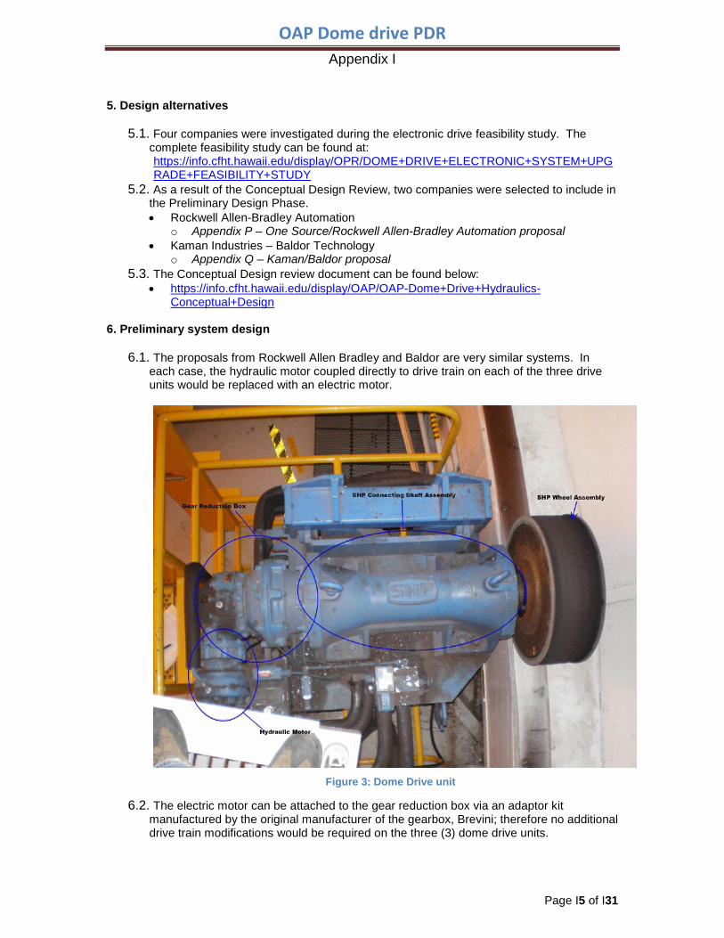
6.1. The proposals from Rockwell Allen Bradley and Baldor are very similar systems. In
each case, the hydraulic motor coupled directly to drive train on each of the three drive units would be replaced with an electric motor.
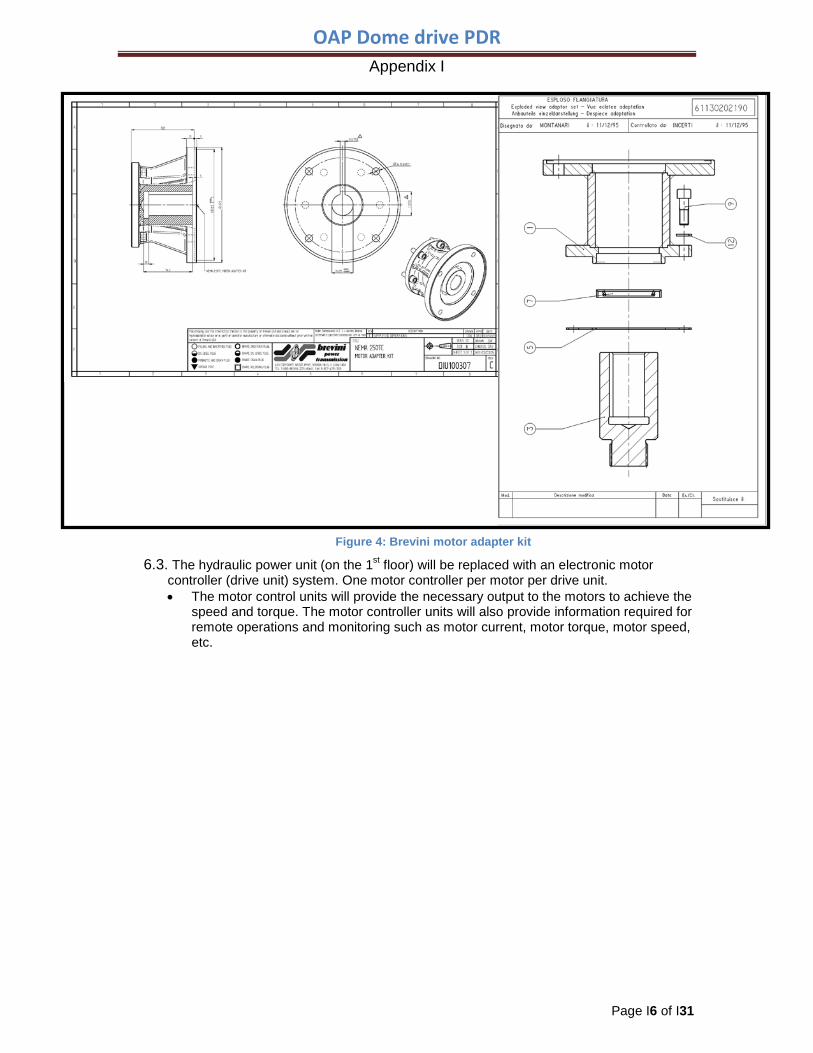
6.2. The electric motor can be attached to the gear reduction box via an adaptor kit manufactured by the original manufacturer of the gearbox, Brevini; therefore no additional drive train modifications would be required on the three (3) dome drive units.
Figure 3: Dome Drive unit
OAP Dome drive PDR Appendix I
Page I6 of I31
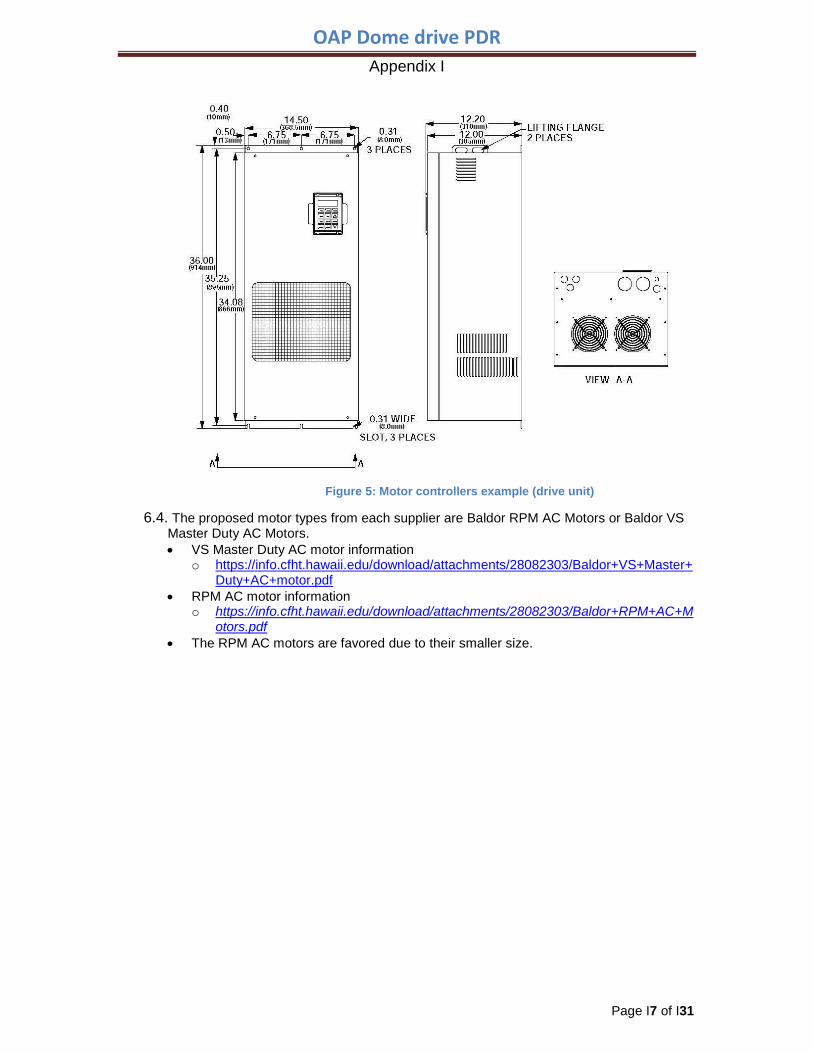
6.3. The hydraulic power unit (on the 1st floor) will be replaced with an electronic motor controller (drive unit) system. One motor controller per motor per drive unit. • The motor control units will provide the necessary output to the motors to achieve the
speed and torque. The motor controller units will also provide information required for remote operations and monitoring such as motor current, motor torque, motor speed, etc.
Figure 4: Brevini motor adapter kit
OAP Dome drive PDR Appendix I
Page I7 of I31
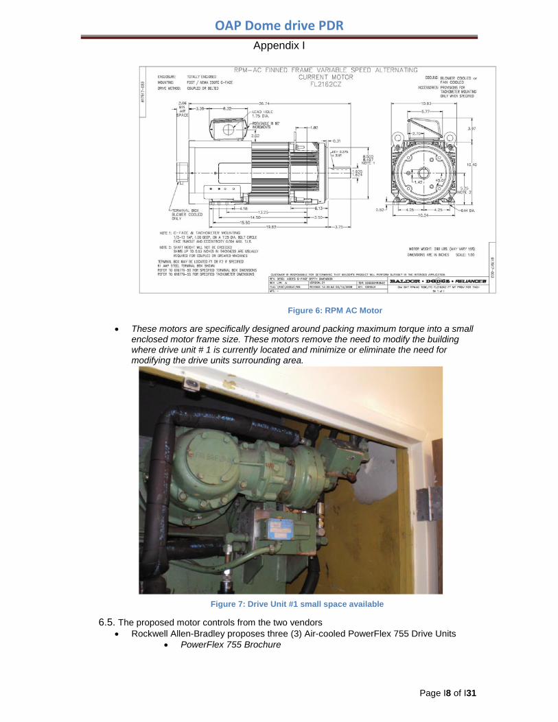
6.4. The proposed motor types from each supplier are Baldor RPM AC Motors or Baldor VS Master Duty AC Motors. • VS Master Duty AC motor information
o https://info.cfht.hawaii.edu/download/attachments/28082303/Baldor+VS+Master+Duty+AC+motor.pdf
• RPM AC motor information o https://info.cfht.hawaii.edu/download/attachments/28082303/Baldor+RPM+AC+M
otors.pdf • The RPM AC motors are favored due to their smaller size.
Figure 5: Motor controllers example (drive unit)
OAP Dome drive PDR Appendix I
Page I8 of I31
• These motors are specifically designed around packing maximum torque into a small enclosed motor frame size. These motors remove the need to modify the building where drive unit # 1 is currently located and minimize or eliminate the need for modifying the drive units surrounding area.
6.5. The proposed motor controls from the two vendors • Rockwell Allen-Bradley proposes three (3) Air-cooled PowerFlex 755 Drive Units
• PowerFlex 755 Brochure
Figure 6: RPM AC Motor
Figure 7: Drive Unit #1 small space available
OAP Dome drive PDR Appendix I
Page I9 of I31
o https://info.cfht.hawaii.edu/download/attachments/28082303/PowerFlex+755+Brochure.PDF
Baldor proposes three (3) Baldor 22H Line Regen AC Motor Control Drive Units • Series 22H Brochure
o https://info.cfht.hawaii.edu/download/attachments/28082303/Series+21H+and+Series+22H+Brochure.pdf
6.6. Motor replacement
• Remove old hydraulic motor and adapter plate o Unbolt the gear reduction box from the SHP shaft assembly, rotate the gear
reduction box counterclockwise 90 degrees, and re-bolt the gear reduction box up to the SHP shaft assembly.
o The gear reduction box needs to be rotated to an upward position to achieve better clearance for the motor.
o Install the new electric motor adapter kit and RPM AC motor.
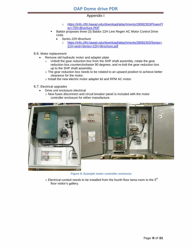
6.7. Electrical upgrades • Drive unit enclosure electrical
o New fuses disconnect and circuit breaker panel is included with the motor controller enclosure for either manufacture.
o Electrical conduit needs to be installed from the fourth floor lama room to the 5th floor visitor’s gallery.
Figure 8: Example motor controller enclosure
OAP Dome drive PDR Appendix I
Page I10 of I31
o The DP4 distribution panel in the back of the lama room will be used to power the equipment on the fifth floor. Electrical wiring (4 strands of 1 awg.) needs to be pulled from the fourth floor
to the fifth floor in preparation for the motor controller enclosure. The electrical wiring will need to be connected to the motor controller
enclosure. o Motor electrical
Electrical conduit (2 sets) will need to be installed and run from the drive enclosure cabinet to each drive unit, three (3) places.
Electrical wiring will need to be pulled thru the conduit. The motors will require 4 strands of 8 gauge wire and a feedback cable which is about ½”in diameter.
6.8. Parking Brakes-not de-acceleration brakes
• Spring set friction type brakes o Who’s controlling these brakes? Need to discuss this
PLC-sends a signal for brake on/off? Motor controller-automatically turns the brakes off/on before or after use. TCS-send information to the brakes-not Bill’s preference Could become an issue for maintenance, need to determine which method
would work best. • Motor brakes/Clutch
o Option (1) Use the weather sensing PLC information to enable (turn on) the motor controller cabinet when the wind speed at the summit exceeds XX knots, i.e., 50 knots.
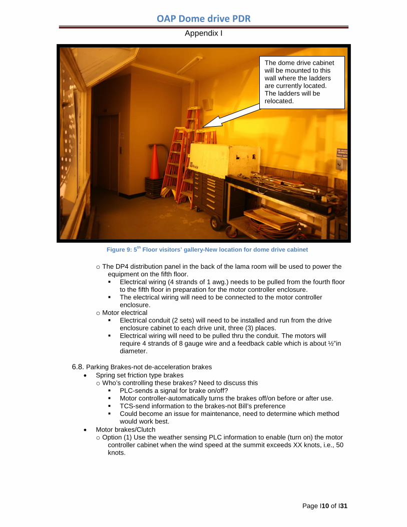
The dome drive cabinet will be mounted to this wall where the ladders are currently located. The ladders will be relocated.
Figure 9: 5th Floor visitors’ gallery-New location for dome drive cabinet
OAP Dome drive PDR Appendix I
Page I11 of I31
Once the motor controllers are turned on, the magnetizing current feed to the three (3) drive motors will apply the torque needed to keep the dome from rotating during heavy winds. Similar to a brake or clutch. • The motor controllers will normally be powered off during non-use to
conserve energy. This option would be viable for very infrequent use. If it was used on a
regular basis we would be better off to install a brake or clutch system initially. As the motors useful life would be affected.
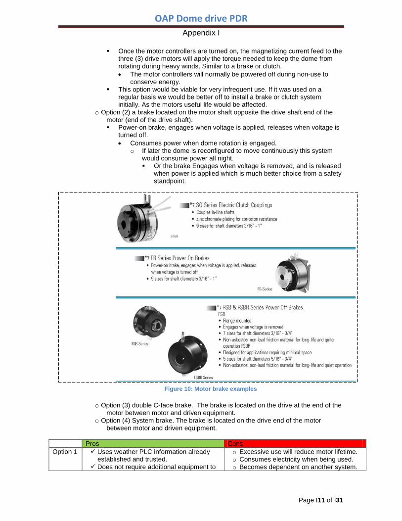
o Option (2) a brake located on the motor shaft opposite the drive shaft end of the motor (end of the drive shaft). Power-on brake, engages when voltage is applied, releases when voltage is
turned off. • Consumes power when dome rotation is engaged.
o If later the dome is reconfigured to move continuously this system would consume power all night. Or the brake Engages when voltage is removed, and is released
when power is applied which is much better choice from a safety standpoint.
o Option (3) double C-face brake. The brake is located on the drive at the end of the motor between motor and driven equipment.
o Option (4) System brake. The brake is located on the drive end of the motor between motor and driven equipment.
Pros Cons Option 1 Uses weather PLC information already
established and trusted. Does not require additional equipment to
o Excessive use will reduce motor lifetime. o Consumes electricity when being used. o Becomes dependent on another system.
Figure 10: Motor brake examples
OAP Dome drive PDR Appendix I
Page I12 of I31
purchase, install, or maintain. Operating duration and wind parameters
can be tweaked in PLC code. Option 2 Simpler installation and maintenance than
option 3 or 4. o Another electro-mechanical device to
maintain. o Consumes continuous power during
dome movement. o Provides failsafe safety feature.
Option 3 o May require additional interface modifications to the adapter kit and motor coupling.
Option 4 .
o May require additional interface modifications to the adapter kit and motor coupling.
Table 1 Motor brake/Clutch Comparison
6.9. Drive unit frame pivot actuator • Since the actuator depends on the hydraulic system pressure to function a
replacement must be installed. o The actuator rotates the frame for replacement of the dome wheel and applies
additional force to the dome drive wheel on the track. • Replacement Actuator options:
o Pneumatic actuator-recommended actuator replacement type Option #1
• *Preference* • 6" Bore x 1.375" Rod x 6" Stroke • ~122 PSI Operating Pressure • Female Clevis Mounting (Different arrangement from current Cylinder) • Three vendors researched
o *Parker Hannifin* o Numatics o Cylindrix
Option #2
• 5" Bore x 1" Rod x 6" Stroke • ~175 PSI Operating Pressure • this pressure is not currently available • Female Clevis Mounting (Same arrangement as current Cylinder) • Three vendors researched
o Parker Hannifin o Numatics o Cylindrix
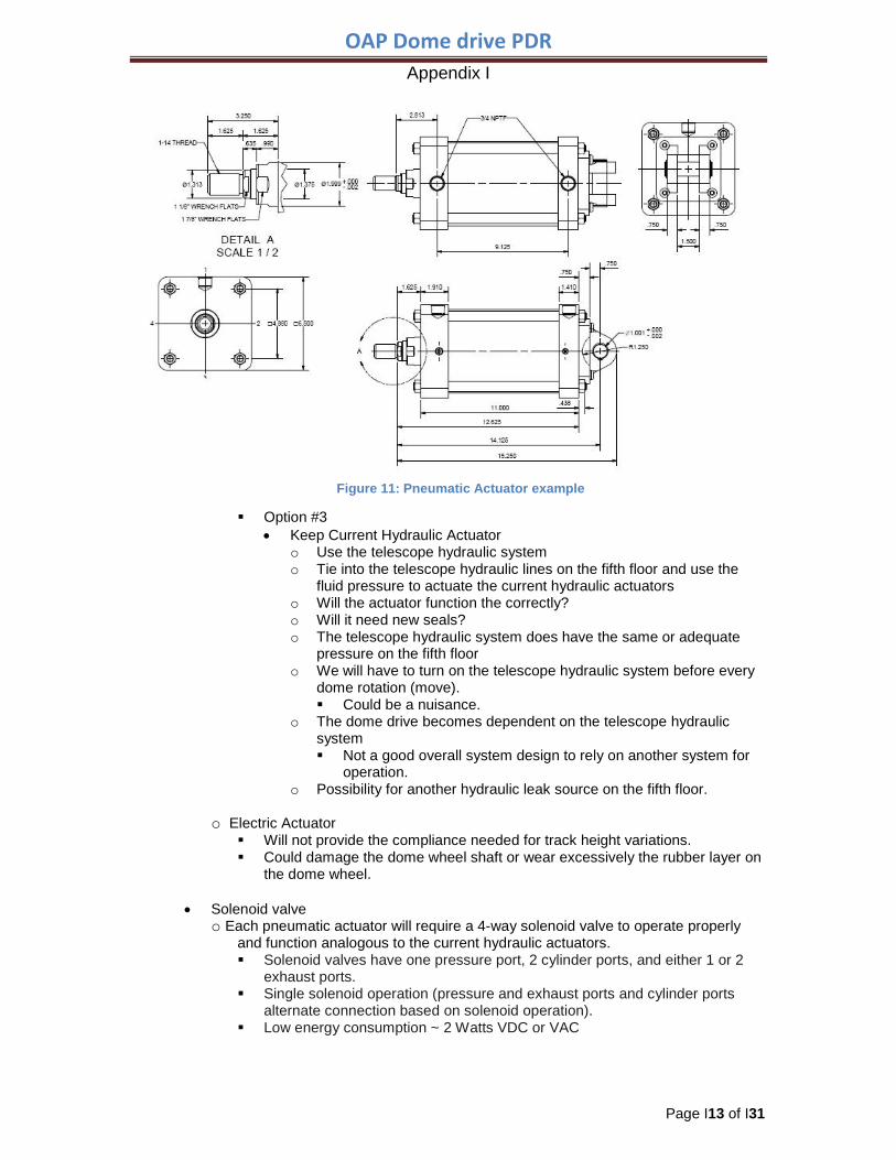
OAP Dome drive PDR Appendix I
Page I13 of I31
Option #3 • Keep Current Hydraulic Actuator
o Use the telescope hydraulic system o Tie into the telescope hydraulic lines on the fifth floor and use the
fluid pressure to actuate the current hydraulic actuators o Will the actuator function the correctly? o Will it need new seals? o The telescope hydraulic system does have the same or adequate
pressure on the fifth floor o We will have to turn on the telescope hydraulic system before every
dome rotation (move). Could be a nuisance.
o The dome drive becomes dependent on the telescope hydraulic system Not a good overall system design to rely on another system for
operation. o Possibility for another hydraulic leak source on the fifth floor.
o Electric Actuator Will not provide the compliance needed for track height variations. Could damage the dome wheel shaft or wear excessively the rubber layer on
the dome wheel.
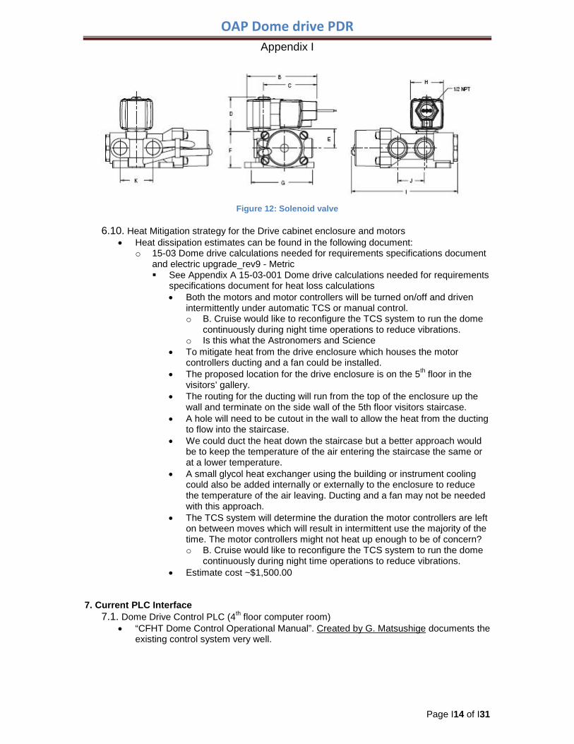
• Solenoid valve o Each pneumatic actuator will require a 4-way solenoid valve to operate properly
and function analogous to the current hydraulic actuators. Solenoid valves have one pressure port, 2 cylinder ports, and either 1 or 2
exhaust ports. Single solenoid operation (pressure and exhaust ports and cylinder ports
alternate connection based on solenoid operation). Low energy consumption ~ 2 Watts VDC or VAC
Figure 11: Pneumatic Actuator example
OAP Dome drive PDR Appendix I
Page I14 of I31
6.10. Heat Mitigation strategy for the Drive cabinet enclosure and motors
• Heat dissipation estimates can be found in the following document: o 15-03 Dome drive calculations needed for requirements specifications document
and electric upgrade_rev9 - Metric See Appendix A 15-03-001 Dome drive calculations needed for requirements
specifications document for heat loss calculations • Both the motors and motor controllers will be turned on/off and driven
intermittently under automatic TCS or manual control. o B. Cruise would like to reconfigure the TCS system to run the dome
continuously during night time operations to reduce vibrations. o Is this what the Astronomers and Science
• To mitigate heat from the drive enclosure which houses the motor controllers ducting and a fan could be installed.
• The proposed location for the drive enclosure is on the 5th floor in the visitors’ gallery.
• The routing for the ducting will run from the top of the enclosure up the wall and terminate on the side wall of the 5th floor visitors staircase.
• A hole will need to be cutout in the wall to allow the heat from the ducting to flow into the staircase.
• We could duct the heat down the staircase but a better approach would be to keep the temperature of the air entering the staircase the same or at a lower temperature.
• A small glycol heat exchanger using the building or instrument cooling could also be added internally or externally to the enclosure to reduce the temperature of the air leaving. Ducting and a fan may not be needed with this approach.
• The TCS system will determine the duration the motor controllers are left on between moves which will result in intermittent use the majority of the time. The motor controllers might not heat up enough to be of concern? o B. Cruise would like to reconfigure the TCS system to run the dome
continuously during night time operations to reduce vibrations. • Estimate cost ~$1,500.00
7. Current PLC Interface 7.1. Dome Drive Control PLC (4th floor computer room)
• “CFHT Dome Control Operational Manual”. Created by G. Matsushige documents the existing control system very well.
Figure 12: Solenoid valve

OAP Dome drive PDR Appendix I
Page I15 of I31
• This Manual describes the location of the PLC, the type, how it interfaces with the TCS, the PLC modules, Schematic Diagram of the Dome Controller, block diagram of the dome controller, etc. o http://www.cfht.hawaii.edu/LocalAccess/dome_control/Operational_Manual.html
8. Modified Current PLC Interface • The dome drive PLC rack has no additional room for extra modules, therefore the
first discussion, Phase 1, will be the interface needed to bring the new electric drive system on-line. Next discussion of the monitoring and status interface will be presented.
• Phase 2 will commence once the new system has been tested thoroughly and is operating correctly under remote operations, then the old system will be removed.
8.1. PHASE 1 Phase 1 will be the integration of the electric drive units into the current dome
drive and PLC infrastructure while minimizing the number of PLC code changes. This allows testing and integration work to be performed during the day and switch back to normal operations in the evening.
8.2. PLC Hardware Block Diagram
8.3. Dome drive motion • The last module in the PLC rack is a 1746 NIO4V 2ch analog input/voltage output
device • This device currently outputs the ± 10V signal to the servo amp for the dome control
movement. The movement is achieved from the input signal to the servo valves on
Figure 13: PLC Block Diagram
OAP Dome drive PDR Appendix I
Page I16 of I31
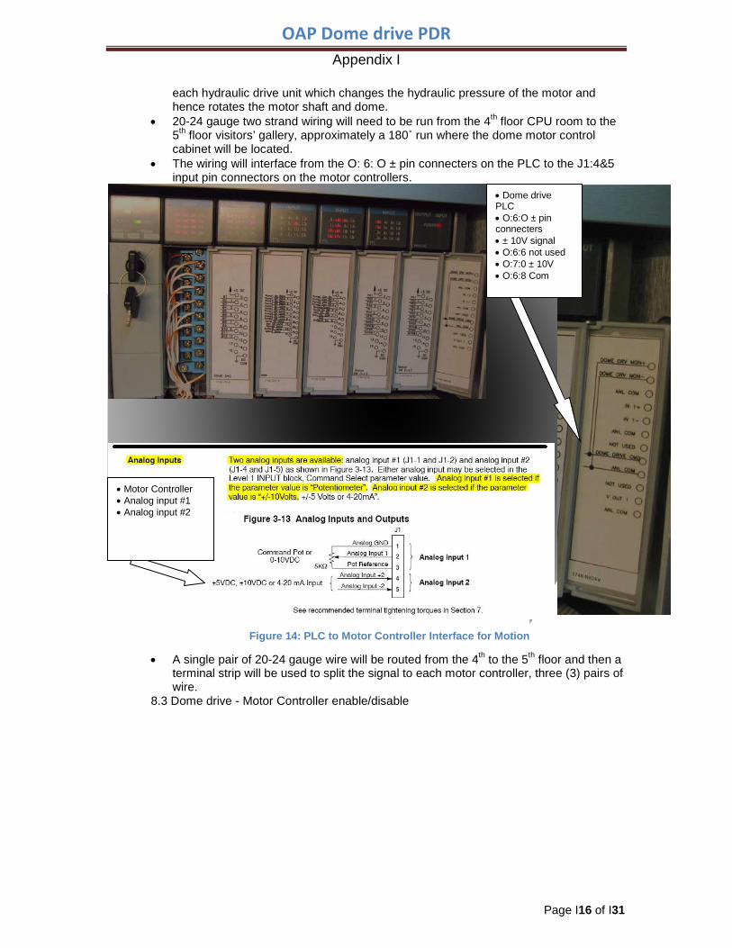
each hydraulic drive unit which changes the hydraulic pressure of the motor and hence rotates the motor shaft and dome.
• 20-24 gauge two strand wiring will need to be run from the 4th floor CPU room to the 5th floor visitors’ gallery, approximately a 180˚ run where the dome motor control cabinet will be located.
• The wiring will interface from the O: 6: O ± pin connecters on the PLC to the J1:4&5 input pin connectors on the motor controllers.
• A single pair of 20-24 gauge wire will be routed from the 4th to the 5th floor and then a
terminal strip will be used to split the signal to each motor controller, three (3) pairs of wire.
8.3 Dome drive - Motor Controller enable/disable
• Motor Controller • Analog input #1 • Analog input #2
• Dome drive PLC • O:6:O ± pin connecters • ± 10V signal • O:6:6 not used • O:7:0 ± 10V • O:6:8 Com
Figure 14: PLC to Motor Controller Interface for Motion
OAP Dome drive PDR Appendix I
Page I17 of I31
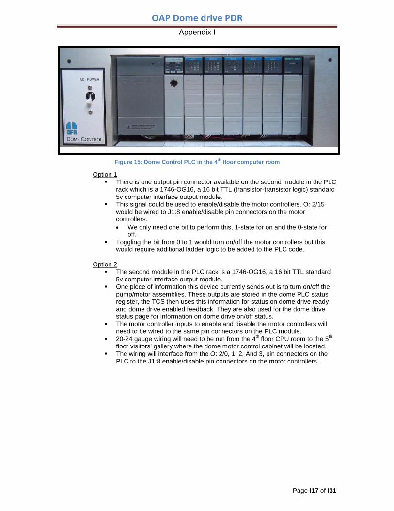
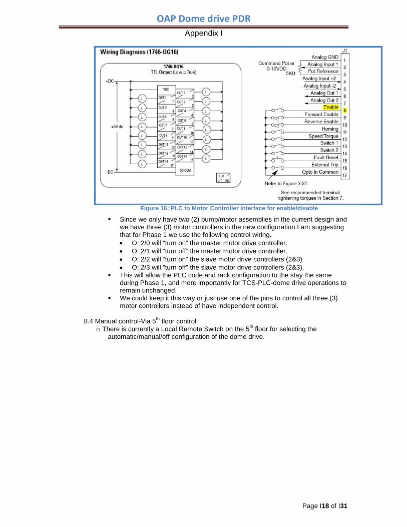
Option 1
There is one output pin connector available on the second module in the PLC rack which is a 1746-OG16, a 16 bit TTL (transistor-transistor logic) standard 5v computer interface output module.
This signal could be used to enable/disable the motor controllers. O: 2/15 would be wired to J1:8 enable/disable pin connectors on the motor controllers. • We only need one bit to perform this, 1-state for on and the 0-state for
off. Toggling the bit from 0 to 1 would turn on/off the motor controllers but this
would require additional ladder logic to be added to the PLC code.
Option 2 The second module in the PLC rack is a 1746-OG16, a 16 bit TTL standard
5v computer interface output module. One piece of information this device currently sends out is to turn on/off the
pump/motor assemblies. These outputs are stored in the dome PLC status register, the TCS then uses this information for status on dome drive ready and dome drive enabled feedback. They are also used for the dome drive status page for information on dome drive on/off status.
The motor controller inputs to enable and disable the motor controllers will need to be wired to the same pin connectors on the PLC module.
20-24 gauge wiring will need to be run from the 4th floor CPU room to the 5th floor visitors’ gallery where the dome motor control cabinet will be located.
The wiring will interface from the O: 2/0, 1, 2, And 3, pin connecters on the PLC to the J1:8 enable/disable pin connectors on the motor controllers.
Figure 15: Dome Control PLC in the 4th floor computer room
OAP Dome drive PDR Appendix I
Page I18 of I31
Since we only have two (2) pump/motor assemblies in the current design and we have three (3) motor controllers in the new configuration I am suggesting that for Phase 1 we use the following control wiring. • O: 2/0 will “turn on” the master motor drive controller. • O: 2/1 will “turn off” the master motor drive controller. • O: 2/2 will “turn on” the slave motor drive controllers (2&3). • O: 2/3 will “turn off” the slave motor drive controllers (2&3).
This will allow the PLC code and rack configuration to the stay the same during Phase 1, and more importantly for TCS-PLC-dome drive operations to remain unchanged.
We could keep it this way or just use one of the pins to control all three (3) motor controllers instead of have independent control.
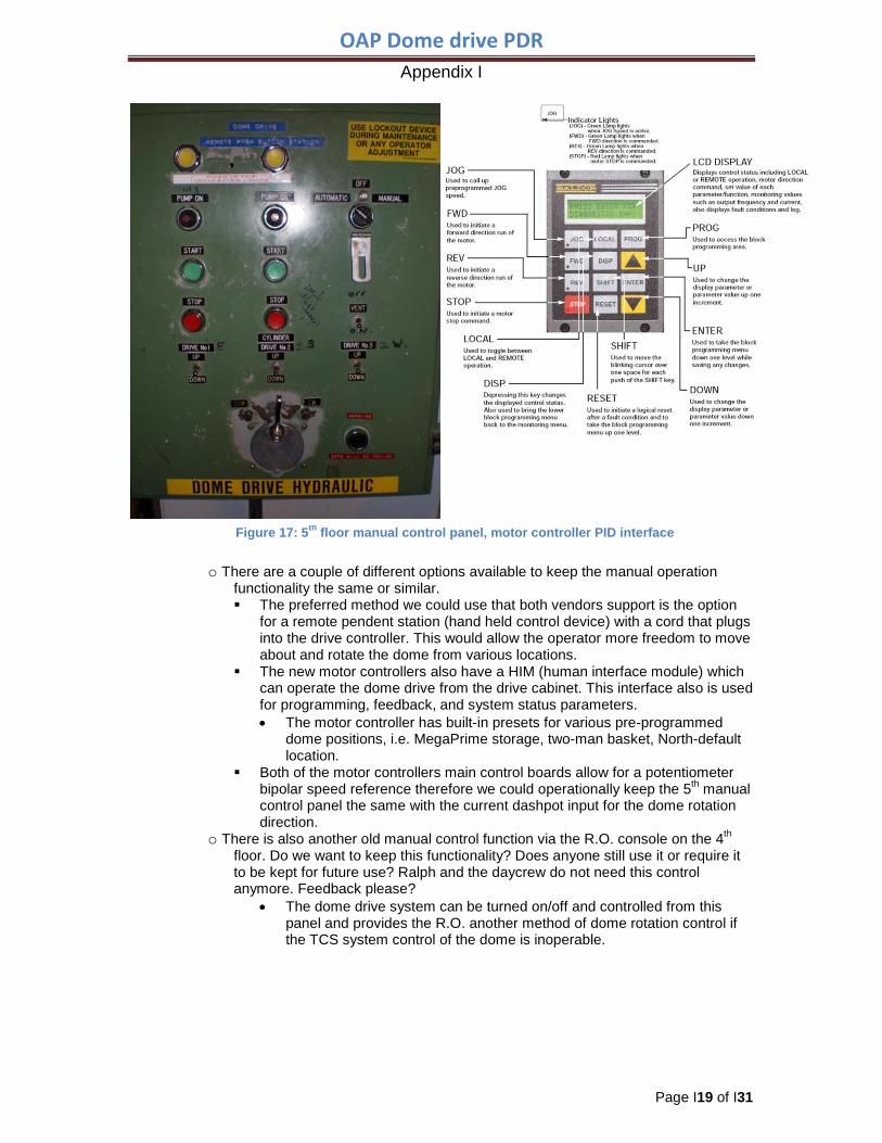
8.4 Manual control-Via 5th floor control
o There is currently a Local Remote Switch on the 5th floor for selecting the automatic/manual/off configuration of the dome drive.
Figure 16: PLC to Motor Controller Interface for enable/disable
OAP Dome drive PDR Appendix I
Page I19 of I31
o There are a couple of different options available to keep the manual operation
functionality the same or similar. The preferred method we could use that both vendors support is the option
for a remote pendent station (hand held control device) with a cord that plugs into the drive controller. This would allow the operator more freedom to move about and rotate the dome from various locations.
The new motor controllers also have a HIM (human interface module) which can operate the dome drive from the drive cabinet. This interface also is used for programming, feedback, and system status parameters. • The motor controller has built-in presets for various pre-programmed
dome positions, i.e. MegaPrime storage, two-man basket, North-default location.
Both of the motor controllers main control boards allow for a potentiometer bipolar speed reference therefore we could operationally keep the 5th manual control panel the same with the current dashpot input for the dome rotation direction.
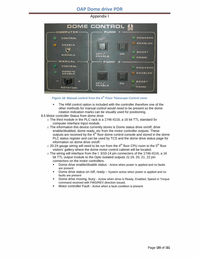
o There is also another old manual control function via the R.O. console on the 4th floor. Do we want to keep this functionality? Does anyone still use it or require it to be kept for future use? Ralph and the daycrew do not need this control anymore. Feedback please?
• The dome drive system can be turned on/off and controlled from this panel and provides the R.O. another method of dome rotation control if the TCS system control of the dome is inoperable.
Figure 17: 5th floor manual control panel, motor controller PID interface
OAP Dome drive PDR Appendix I
Page I20 of I31
The HIM control option is included with the controller therefore one of the other methods for manual control would need to be present so the dome rotation indication marks can be visually used for positioning.
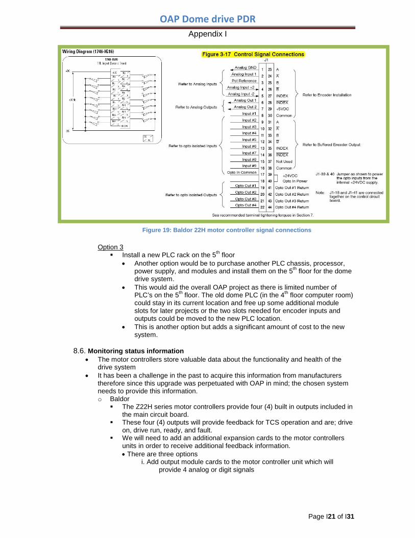
8.5 Motor controller Status from dome drive o The third module in the PLC rack is a 1746-IG16, a 16 bit TTL standard 5v
computer interface Input module. o The information this device currently stores is Dome status drive on/off, drive
enable/disabled, dome ready, etc from the motor controller outputs. These outputs are received by the 4th floor dome control console and stored in the dome PLC status register and can be used by TCS and the dome drive status page for information on dome drive on/off.
o 20-24 gauge wiring will need to be run from the 4th floor CPU room to the 5th floor visitors’ gallery where the dome motor control cabinet will be located.
o The wiring will interface from the I: 3/10-14 pin connecters of the 1746-IG16, a 16 bit TTL output module to the Opto isolated outputs J1:19, 20, 21, 22 pin connectors on the motor controllers. Dome drive enable/disable status - Active when power is applied and no faults
are present Dome drive status on /off, ready – System active when power is applied and no
faults are present Dome drive moving, busy - Active when drive is Ready, Enabled, Speed or Torque
command received with FWD/REV direction issued. Motor controller Fault - Active when a fault condition is present
Figure 18: Manual control from the 4th Floor Telescope Control room
OAP Dome drive PDR Appendix I
Page I21 of I31
Option 3
Install a new PLC rack on the 5th floor • Another option would be to purchase another PLC chassis, processor,
power supply, and modules and install them on the 5th floor for the dome drive system.
• This would aid the overall OAP project as there is limited number of PLC’s on the 5th floor. The old dome PLC (in the 4th floor computer room) could stay in its current location and free up some additional module slots for later projects or the two slots needed for encoder inputs and outputs could be moved to the new PLC location.
• This is another option but adds a significant amount of cost to the new system.
8.6. Monitoring status information • The motor controllers store valuable data about the functionality and health of the
drive system • It has been a challenge in the past to acquire this information from manufacturers
therefore since this upgrade was perpetuated with OAP in mind; the chosen system needs to provide this information. o Baldor
The Z22H series motor controllers provide four (4) built in outputs included in the main circuit board.
These four (4) outputs will provide feedback for TCS operation and are; drive on, drive run, ready, and fault.
We will need to add an additional expansion cards to the motor controllers units in order to receive additional feedback information. • There are three options
i. Add output module cards to the motor controller unit which will provide 4 analog or digit signals
Figure 19: Baldor 22H motor controller signal connections
OAP Dome drive PDR Appendix I
Page I22 of I31
These outputs can be chosen from a table off many different types of conditions such as; speed, torque, voltage, current, etc. This will require an empty slot in the PLC chassis for an analog input module card and the card itself. This method seems simplistic and would provide analog signals to be stored in the PLC registry which could provide the information needed for a status monitoring page.
ii. Add a serial interface communication (RS232) expansion board to the motor controllers This would allow use to receive feedback information for status via and RS232 cable to a Pearle device Using the Pearle device we could receive the information via and Ethernet cable and get the various status information we need. This method also seems straightforward and would provide information needed for a status monitoring page.
iii. Add a device net Ethernet communication output card to the motor controller which will allow status information from the motor controller to be stored in the PLC memory. This may require an empty slot in the PLC chassis for a device net module card. If we use the device net output card an additional device net PLC module will be required to accept the status information and complete the communication link between the two devices This method still does not allow us to talk directly to the motor controller with either a Linux PC or AB PLC. .Device Net protocol requires additional infrastructures to achieve a network connection and communication between the motor controller and PLC. The amount of work involved to achieve the device net method appears unreasonable.
o Rockwell Allen-Bradley The PowerFlex 755 motor controllers series provides 6 digital inputs that may
also be configured as outputs but this information has only been provided to me by word of mouth and I have yet to find the proof in the manual
These outputs will provide feedback for TCS operation as well such as; drive on, drive run, ready, and fault.
We will need to add an additional expansion cards to the motor controllers units in order to receive additional feedback information. • The options
i. As the manufacturer has specified the drive package for our specific application, a Compactlogix processor has be implemented to synchronize the three (3) individual motor controllers. Since the Compactlogix processor supports EtherNet/IP
network and communication protocol These outputs can also be chosen from a table of many
different types of conditions such as; speed, torque, voltage, current, etc.
Ideally all status information from the motor controller should be available to the PLC so the TCS system can acquire this information.
ii. Add a device net Ethernet communication output card to the motor controller which will allow status information from the motor controller to be stored in the PLC memory.
OAP Dome drive PDR Appendix I
Page I23 of I31
This may require an empty slot in the PLC chassis for a device net module card.
If we use the device net output card an additional device net PLC module will be required to accept the status information and complete the communication link between the two devices
This method still does not allow us to talk directly to the motor controller with either a Linux PC or AB PLC
Device Net protocol requires additional infrastructures to achieve a network connection and communication between the motor controller and PLC.
The work needed to implement this method is similar to the description above for the Baldor motor controller and also appears to be unreasonable.
8.7. Comparison of Baldor vs. Rockwell Allen-Bradley drive units (motor controllers)
• Baldor o The proposed Baldor system is similar to the system that is currently operating
effectively at Keck. The potential to share experience, knowledge, and troubleshooting expertise could be very valuable.
o Bill Colton is the District Manager for Baldor and the gentleman who came out as a consultant to look at our system. He is the same person who specified, commissioned, programmed, and installed Keck’s current drive system.
• Rockwell Allen-Bradley o The existing PLC infrastructure for OAP is largely Rockwell Allen-Bradley products,
and the field engineer in Honolulu has a proven track record of good service with CFHT over the years. The additional work that would be required to integrate the new electric drive system would be very similar for either of the proposed systems: Room modifications No modifications would be required if the RPM AC motors are selected. See
figure 6 and figure 0. Although I see no reason to keep the walls and room separation and suggest
removing them to allow for better access to the drive units for access, maintenance, and repairs. • I assume the walls were installed to keep the instruments and detectors
stored in the room clean and free from hydraulic leaks. • This room is now used for storage of spacers for instruments and other
misc equipment.
Table 2: Comparison of Baldor vs. Rockwell Allen-Bradley
Baldor
Rockwell Allen-Bradley
Motors
• Almost any motor will work with the proposed system
• Recommends Baldor motors for driven applications
• Almost any motor will work with the proposed system
• Recommends and specifies Baldor motors for driven applications
Regenerative • The 22H motor controller is a proven and
understood technology, Keck implementation
• The 755 Motor controller is a new line of motor controller products
• One Source Supplier has little experience with newer technology.
Support
• Excellent engineering support from Baldor and Kaman
• Oahu merchandise supplier for Baldor products is Kaman Industrial Technologies
• Excellent track record over the years for support from Allen-Bradley.
• Oahu merchandise supplier for Rockwell-Allen Bradley products is One Source
OAP Dome drive PDR Appendix I
Page I24 of I31
• Lower priced of the two for integration and commissioning
Berkley Engineering •
Communication
• Motor controller provides 4 optical (digit) outputs built into the unit.
• Analog output cards can be added to the motor controller for feedback such as current, voltage, speed, etc.
• RS232 serial interface using a Pearle device will allow Ethernet communication capabilities for remote status
• Requires not additional software or processors
• Motor controller requires a Compactlogix processor to communicate with our SLC 505
• This Compactlogix processor requires a software upgrade to RSLogix 5000
• The processor allows communication by Ethernet IP cable directly to the SLC 505
• Adds another processor to maintain (with a spare) and additional software licenses to purchase and support
Versatility • The 22H motor control is flexible and can be configured for different applications
• The 755 motor control is extremely versatile and can be configured for multiple applications
9. Motor sizing
9.6. From the dome drive electrical upgrade requirements document and the corresponding
calculations needed to determine the system specifications the following motor sizing justification are incorporated below.
Motor Sizing Requirement Requirement • Full running speed (60˚/min) - power output
requirement
• Physical measurement of current system • 3.4 Horsepower (HP) output power needed
per drive wheel
Motor inefficiency
• The RPM AC motors are 94% efficient, therefore the motor inefficiency that must be accounted for is an additional 6%
• 3.4 HP ÷ .94 = 3.6 Hp • The addition added to the requirement = 3.6
HP
Motor de-rating
• The Baldor RPM AC motors and Line Regen AC flux vector controllers have to be de-rated for 14,000ft elevation operation.
• The de-rated was calculated to be 32.4%
• 3 3.6 HP ÷ .676 = 5.35 HP • The addition added to the requirement = 5.35
HP
Safety Factor • From the requirements document of the dome
drive electric upgrade • The safety factor = SF = 2.5-3
• 5.35 HP x 2.5 = 13.4 HP • 5.35 HP x 2.5 = 16.05 HP • The motors should be sized between • 13.4 HP to 16.05 HP per drive wheel (unit)
Reasons for upgrading to a larger motor configuration
Maintenance • A larger motor when compared to a smaller equivalent motor would have a longer run life and require replacement less often
Drive train capacity • The current drive train (gearbox is the limiting component) is rated to accommodate a 20HP motor
Heat Production • A larger motor with the same load as a smaller equivalent motor will produce less heat. Designing for the
future • Future projects may increase the weight of the dome and could affect later performance of the drive
system Function • If one drive fails, we could still operate at full speed (60˚/min) with two drives.
Reliability • A larger motor when compared to a smaller equivalent will have a longer lifetime at the same duty cycle.
Cost difference • The cost difference between a 15HP system and a 20HP is minimal. Unforeseen advantages
• Larger motors could provide the torque needed to break ice built up on the dome • Larger motors could provide the torque needed to battle high winds
Table 3: Motor Sizing
10. PHASE 2
OAP Dome drive PDR Appendix I
Page I25 of I31
Phase 2 will be removing the old hydraulic system; lines, motors, valves, components, etc. and modifying the PLC configuration and PLC code. Since the current infrastructure encompasses module cards and ladder logic for soon to be obsolete hydraulic components and inputs/outputs the PLC system should be cleaned up and some housekeeping should be performed to remove these instances. Bill would also like to begin work with TCS to actively control the PID (Proportional Integral derivative) which controls the dome slew speed and acceleration profiles.
10. Draft Interface Definition
10.1. Integration steps • See time and resource estimates
10.2. Mechanical interfaces • Described above
10.3. Electrical Interfaces • Described above
10.4. Optical interfaces • None
10.5. Dependences on subprojects • The Dome Drive System must integrate with the TCS and OAP PLC control systems
for autonomous operation. 10.6. Remote monitoring of the dome drive system will provide the following state/status:
• On/off state of motor controllers • Rotation speed of each motor • Amperage/torque of each motor • Failure state of motor controllers (detection and notification)
11. Safety implications
11.1. The new electric drive system introduces additional electrical equipment at the observatory with high voltage. However the same safety procedures and PPE will be used for installation and servicing only by qualified staff or service providers.
11.2. The electrical dome drive system upgrade eliminates hazards of the existing hydraulic system, such as large leaks, slip hazards, environmental waste cleanup, and injuries to personnel from leak to name a few.
11.3. An Anti-rotation system (Clutch/Brake/Anti-rotation device) must be in place to prevent unintentional movement of the dome when excessive winds are present.
12. Time and resource estimates
12.1. Table of time, suggested person needed, and remaining design work and implementation
12.2. All values shown are estimates for time needed to complete the work listed. 12.3. The UKIRT aluminization is scheduled to take place July 2010 which could adversely
affect the schedule. 12.4. The second semester schedule also influences operations and projects which will
change priorities and influence schedule priorities. 12.5. The OAP telescope hydraulics project implementation work is also scheduled during
the same timeframe.
Resource Days Description
Post PDR and Detailed Design
Work
Hardware, mechanical
SB 1 Order Brevini Motor Adapter kit Order Spare Motor
SB, Daycrew 3 Finalize Actuator selection SB 1 Order Pneumatic actuators
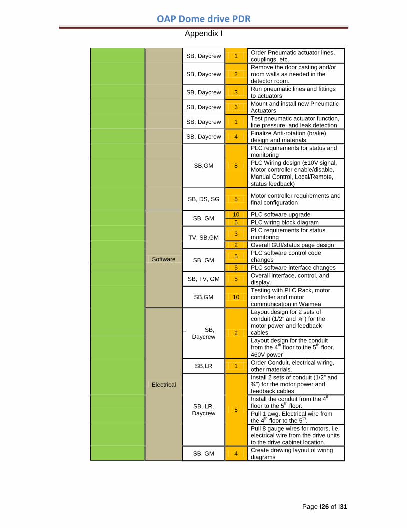
OAP Dome drive PDR Appendix I
Page I26 of I31
SB, Daycrew 1 Order Pneumatic actuator lines, couplings, etc.
SB, Daycrew 2 Remove the door casting and/or room walls as needed in the detector room.
SB, Daycrew 3 Run pneumatic lines and fittings to actuators
SB, Daycrew 3 Mount and install new Pneumatic Actuators
SB, Daycrew 1 Test pneumatic actuator function, line pressure, and leak detection
SB, Daycrew 4 Finalize Anti-rotation (brake) design and materials.
SB,GM 8
PLC requirements for status and monitoring PLC Wiring design (±10V signal, Motor controller enable/disable, Manual Control, Local/Remote, status feedback)
SB, DS, SG 5 Motor controller requirements and final configuration
Software
SB, GM 10 PLC software upgrade 5 PLC wiring block diagram
TV, SB,GM 3 PLC requirements for status monitoring
2 Overall GUI/status page design
SB, GM 5 PLC software control code
changes 5 PLC software interface changes
SB, TV, GM 5 Overall interface, control, and display.
SB,GM 10 Testing with PLC Rack, motor controller and motor communication in Waimea
Electrical
1. SB, Daycrew 2
Layout design for 2 sets of conduit (1/2” and ¾”) for the motor power and feedback cables. Layout design for the conduit from the 4th floor to the 5th floor. 460V power
SB,LR 1 Order Conduit, electrical wiring, other materials.
SB, LR, Daycrew 5
Install 2 sets of conduit (1/2” and ¾”) for the motor power and feedback cables. Install the conduit from the 4th floor to the 5th floor. Pull 1 awg. Electrical wire from the 4th floor to the 5th. Pull 8 gauge wires for motors, i.e. electrical wire from the drive units to the drive cabinet location.
SB, GM 4 Create drawing layout of wiring diagrams
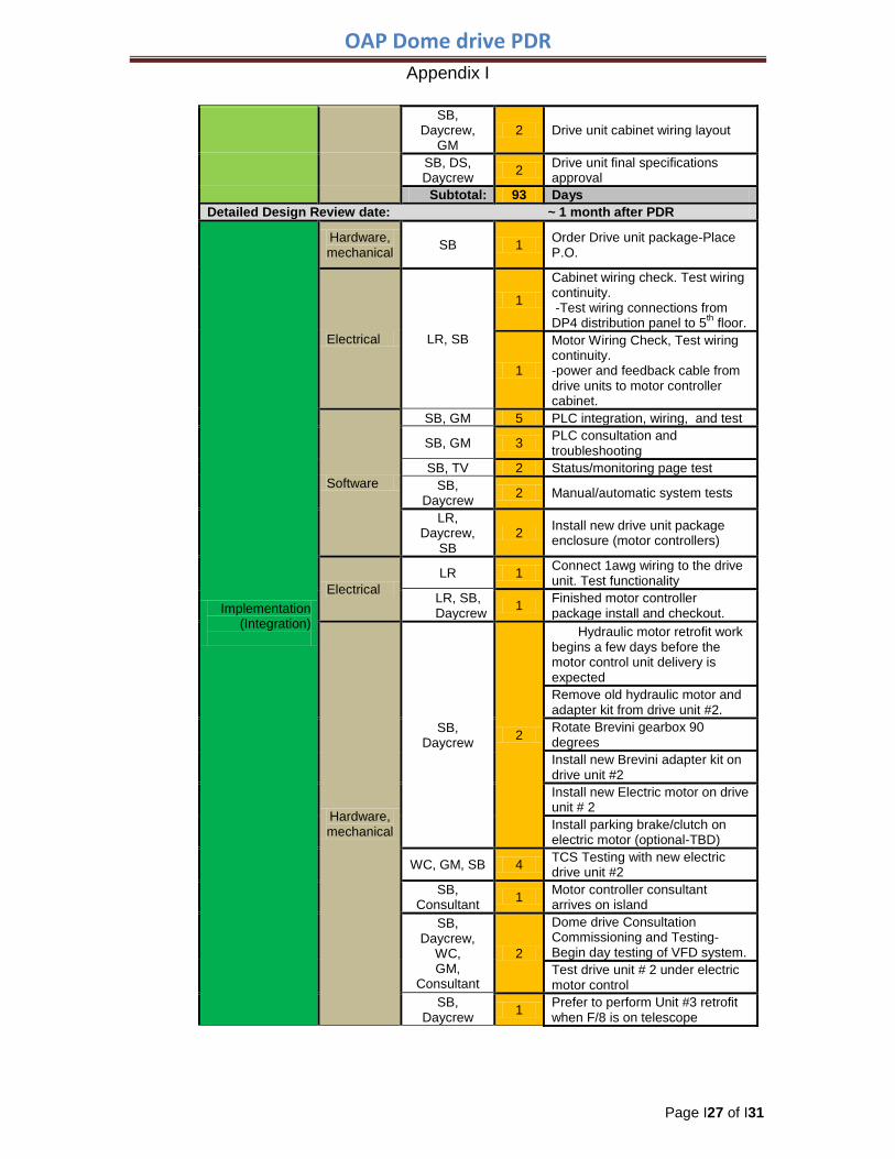
OAP Dome drive PDR Appendix I
Page I27 of I31
SB, Daycrew,
GM 2 Drive unit cabinet wiring layout
SB, DS, Daycrew 2 Drive unit final specifications
approval Subtotal: 93 Days
Detailed Design Review date: ~ 1 month after PDR
Implementation (Integration)
Hardware, mechanical SB 1 Order Drive unit package-Place
P.O.
Electrical LR, SB
1
Cabinet wiring check. Test wiring continuity. -Test wiring connections from DP4 distribution panel to 5th floor.
1
Motor Wiring Check, Test wiring continuity. -power and feedback cable from drive units to motor controller cabinet.
Software
SB, GM 5 PLC integration, wiring, and test
SB, GM 3 PLC consultation and troubleshooting
SB, TV 2 Status/monitoring page test SB,
Daycrew 2 Manual/automatic system tests
LR, Daycrew,
SB 2 Install new drive unit package
enclosure (motor controllers)
Electrical LR 1 Connect 1awg wiring to the drive
unit. Test functionality LR, SB, Daycrew 1 Finished motor controller
package install and checkout.
Hardware, mechanical
SB, Daycrew 2
2. Hydraulic motor retrofit work begins a few days before the motor control unit delivery is expected Remove old hydraulic motor and adapter kit from drive unit #2. Rotate Brevini gearbox 90 degrees Install new Brevini adapter kit on drive unit #2 Install new Electric motor on drive unit # 2 Install parking brake/clutch on electric motor (optional-TBD)
WC, GM, SB 4 TCS Testing with new electric drive unit #2
SB, Consultant 1 Motor controller consultant
arrives on island SB,
Daycrew, WC, GM,
Consultant
2
Dome drive Consultation Commissioning and Testing-Begin day testing of VFD system. Test drive unit # 2 under electric motor control
SB, Daycrew 1 Prefer to perform Unit #3 retrofit
when F/8 is on telescope
OAP Dome drive PDR Appendix I
Page I28 of I31
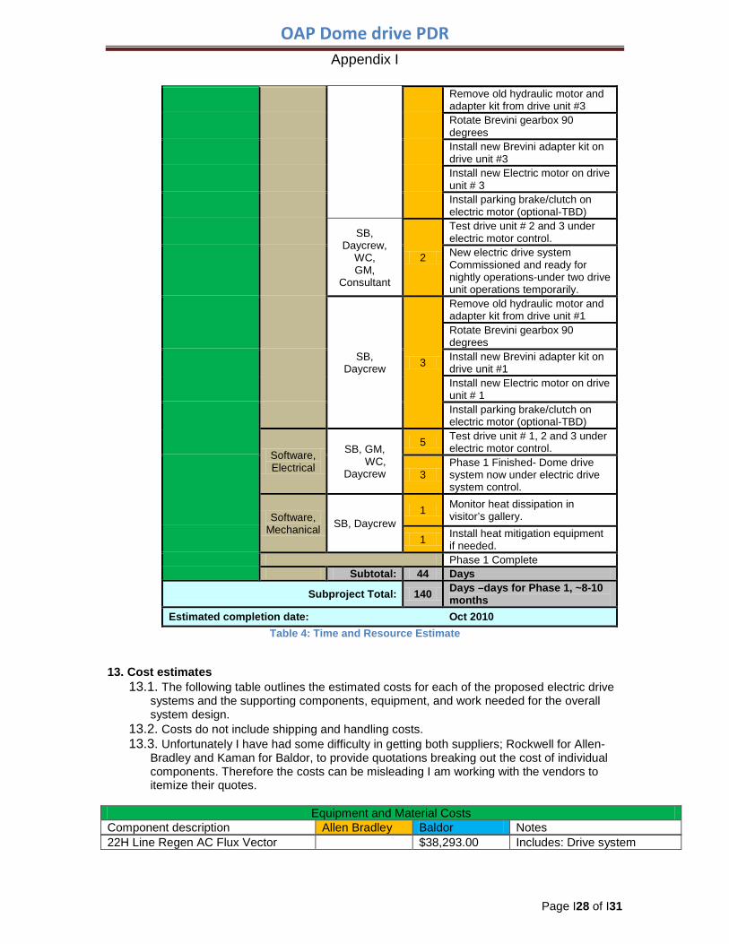
Remove old hydraulic motor and adapter kit from drive unit #3 Rotate Brevini gearbox 90 degrees Install new Brevini adapter kit on drive unit #3 Install new Electric motor on drive unit # 3 Install parking brake/clutch on electric motor (optional-TBD)
SB, Daycrew,
WC, GM,
Consultant
2
Test drive unit # 2 and 3 under electric motor control. New electric drive system Commissioned and ready for nightly operations-under two drive unit operations temporarily.
SB, Daycrew 3
Remove old hydraulic motor and adapter kit from drive unit #1 Rotate Brevini gearbox 90 degrees Install new Brevini adapter kit on drive unit #1 Install new Electric motor on drive unit # 1 Install parking brake/clutch on electric motor (optional-TBD)
Software, Electrical
SB, GM, WC,
Daycrew
5 Test drive unit # 1, 2 and 3 under electric motor control.
3 Phase 1 Finished- Dome drive system now under electric drive system control.
Software, Mechanical SB, Daycrew
1 Monitor heat dissipation in visitor’s gallery.
1 Install heat mitigation equipment if needed.
Phase 1 Complete Subtotal: 44 Days
Subproject Total: 140 Days –days for Phase 1, ~8-10 months
Estimated completion date: Oct 2010 Table 4: Time and Resource Estimate
13. Cost estimates
13.1. The following table outlines the estimated costs for each of the proposed electric drive systems and the supporting components, equipment, and work needed for the overall system design.
13.2. Costs do not include shipping and handling costs. 13.3. Unfortunately I have had some difficulty in getting both suppliers; Rockwell for Allen-
Bradley and Kaman for Baldor, to provide quotations breaking out the cost of individual components. Therefore the costs can be misleading I am working with the vendors to itemize their quotes.
Equipment and Material Costs
Component description Allen Bradley Baldor Notes 22H Line Regen AC Flux Vector $38,293.00 Includes: Drive system
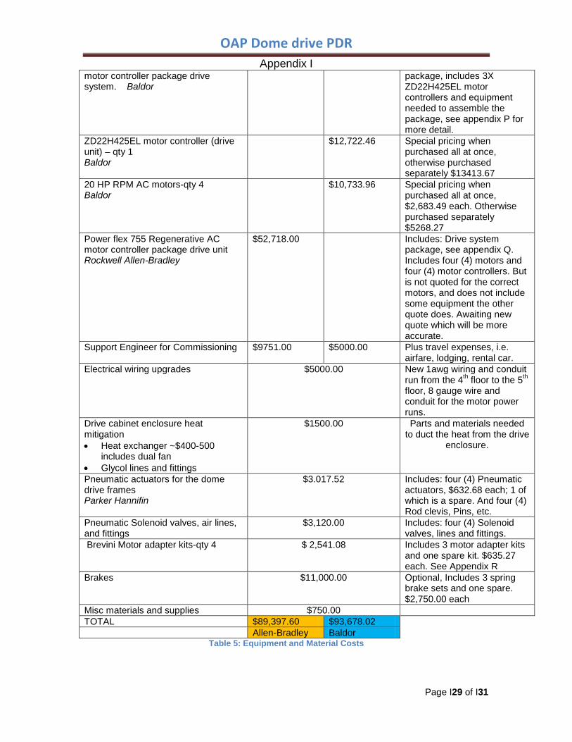
OAP Dome drive PDR Appendix I
Page I29 of I31
motor controller package drive system. Baldor
package, includes 3X ZD22H425EL motor controllers and equipment needed to assemble the package, see appendix P for more detail.
ZD22H425EL motor controller (drive unit) – qty 1 Baldor
$12,722.46 Special pricing when purchased all at once, otherwise purchased separately $13413.67
20 HP RPM AC motors-qty 4 Baldor
$10,733.96 Special pricing when purchased all at once, $2,683.49 each. Otherwise purchased separately $5268.27
Power flex 755 Regenerative AC motor controller package drive unit Rockwell Allen-Bradley
$52,718.00 Includes: Drive system package, see appendix Q. Includes four (4) motors and four (4) motor controllers. But is not quoted for the correct motors, and does not include some equipment the other quote does. Awaiting new quote which will be more accurate.
Support Engineer for Commissioning $9751.00 $5000.00 Plus travel expenses, i.e. airfare, lodging, rental car.
Electrical wiring upgrades
$5000.00 New 1awg wiring and conduit run from the 4th floor to the 5th floor, 8 gauge wire and conduit for the motor power runs.
Drive cabinet enclosure heat mitigation • Heat exchanger ~$400-500
includes dual fan • Glycol lines and fittings
$1500.00 Parts and materials needed to duct the heat from the drive
enclosure.
Pneumatic actuators for the dome drive frames Parker Hannifin
$3.017.52 Includes: four (4) Pneumatic actuators, $632.68 each; 1 of which is a spare. And four (4) Rod clevis, Pins, etc.
Pneumatic Solenoid valves, air lines, and fittings
$3,120.00 Includes: four (4) Solenoid valves, lines and fittings.
Brevini Motor adapter kits-qty 4 $ 2,541.08 Includes 3 motor adapter kits and one spare kit. $635.27 each. See Appendix R
Brakes $11,000.00 Optional, Includes 3 spring brake sets and one spare. $2,750.00 each
Misc materials and supplies $750.00 TOTAL $89,397.60 $93,678.02 Allen-Bradley Baldor
Table 5: Equipment and Material Costs

OAP Dome drive PDR Appendix I
Page I30 of I31
OAP Dome drive PDR Appendix I
Page I31 of I31
Appendix Appendix P – One Source/Rockwell Allen-Bradley proposal Appendix Q – Kaman/Baldor proposal Appendix R – Kaman/Baldor motor adapter kit proposal Appendix S –PowerFlex 750-Series AC Drives Users Manual