obstruction behind mse walls and feasible solutions
TRANSCRIPT

Obstructions behind MSE Walls and Feasible Solutions
David Hutchinson. P.E.Director of Engineering
Southwest Geotechnical ConferenceTexas DOT
June 22-24, 2021
1

Obstruction behind MSE wall and Feasible Solutions
Typical MSE Wall
Facing Element
Select Backfill
SoilReinforcement
2

Obstruction behind MSE wall and Feasible Solutions
Plan View Elevation View
Obstructions hinder the Normal placement of the soil reinforcementthat can affect the MSE Wall Structure.
This presentation will present feasible solutions to deal with obstruction in the MSE Wall backfill.
Vertical Obstructions Horizontal Obstructions
3

Obstruction behind MSE wall and Feasible Solutions
1. Design the surrounding reinforcement layers to carry the additional loadwhich would have been carried by the severed reinforcements.
General Guidelines - Obstructions in the MSE wall Backfill
AASHTO Section 11.10.10.4
4

Obstruction behind MSE wall and Feasible Solutions
2. Place a structural frame around theobstruction
3. Skew the reinforcements around theobstruction.
General Guidelines - Obstructions in the MSE wall Backfill
AASHTO Section 11.10.10.4
5

Obstruction behind MSE wall and Feasible Solutions
Section 5.4 of FHWA-NHI-10-024: Design and Construction of Mechanically Stabilized Earth Walls and Reinforced Soil Slopes – Volume I (FHWA, 2009a).
“A Comprehensive Field Guide for Reconfiguration of MSE Reinforcement Around Obstructions.” research study done by Texas Tech University on - Jayawickrama, Ghebrab, and Lawson.
Additional General Guidelines
6
Obstruction behind MSE wall and Feasible Solutions
1. General guidance only
3. Does not cover the more complex cases.
2. Guidance for only two types of obstructions behind the MSE wall – an inlet and a circular shaft.
The AASHTO recommendations provides:
7
Obstruction behind MSE wall and Feasible Solutions
Drainage Structures Behind MSE Walls
8
Obstruction behind MSE wall and Feasible Solutions
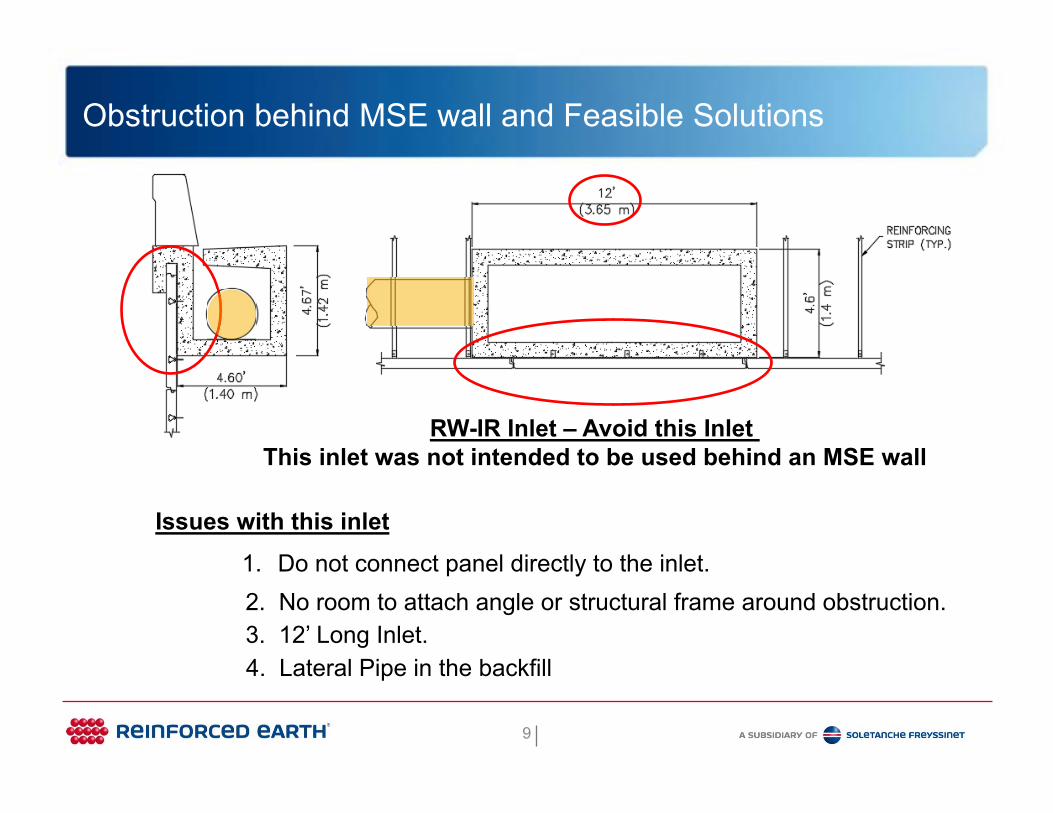
RW-IR Inlet – Avoid this Inlet This inlet was not intended to be used behind an MSE wall
4. Lateral Pipe in the backfill
Issues with this inlet1. Do not connect panel directly to the inlet.2. No room to attach angle or structural frame around obstruction.3. 12’ Long Inlet.
9

Obstruction behind MSE wall and Feasible Solutions
Issues with this inlet1. 16’-4” long inlet – undesirable large skew angle. 2. Design for Bin Pressure between Inlet and panel.
4. Taller inlets – check for the stability of Inlet - may require backer panels 3. Special backfill required
Curb Inlet – A little better but still Avoid this type of Inlet
H
RCP out backof inlet - Good
10
Obstruction behind MSE wall and Feasible Solutions
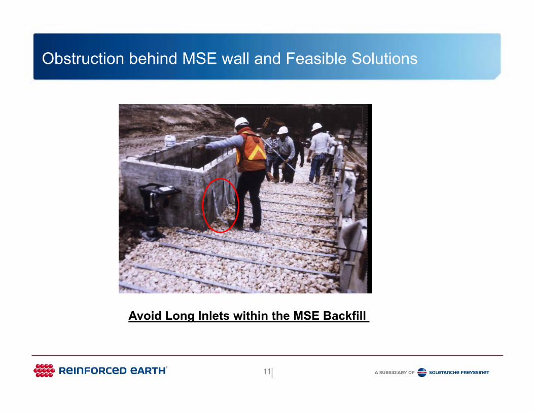
Avoid Long Inlets within the MSE Backfill
11

Obstruction behind MSE wall and Feasible Solutions
1. Difficult to construct and compact around pipes.
Avoid Lateral Pipe in MSE Wall Backfill
2. Skew Soil Reinforcements over or beneath pipe.
4. Flexible connections in RCP should be used and designed to tolerate theestimated movement and stress –NHI Manual.
3. Things change in field - contractor takes matters into his own hands.
12

Obstruction behind MSE wall and Feasible Solutions
Avoid Lateral Pipe in MSE Wall Backfill
13

Obstruction behind MSE wall and Feasible Solutions
Avoid Lateral Pipe in MSE Wall Backfill
14
Obstruction behind MSE wall and Feasible Solutions
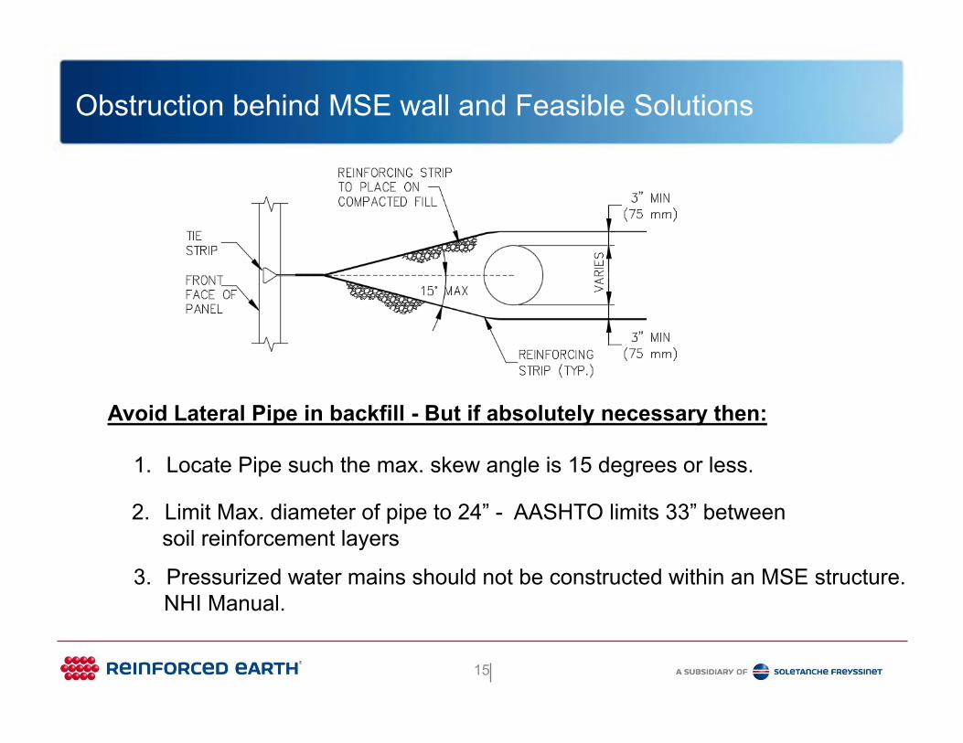
1. Locate Pipe such the max. skew angle is 15 degrees or less.
Avoid Lateral Pipe in backfill - But if absolutely necessary then:
2. Limit Max. diameter of pipe to 24” - AASHTO limits 33” betweensoil reinforcement layers
3. Pressurized water mains should not be constructed within an MSE structure.NHI Manual.
15
Obstruction behind MSE wall and Feasible Solutions
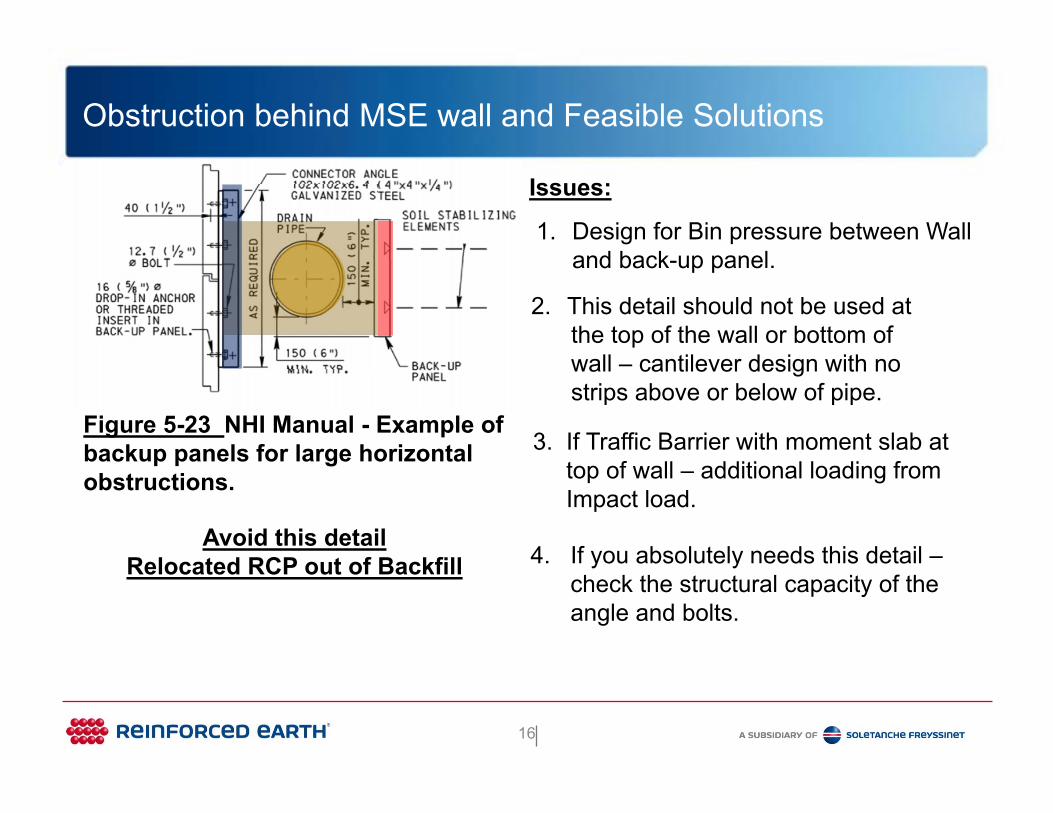
1. Design for Bin pressure between Wall and back-up panel.
Avoid this detailRelocated RCP out of Backfill
2. This detail should not be used atthe top of the wall or bottom ofwall – cantilever design with nostrips above or below of pipe.
Figure 5-23 NHI Manual - Example of backup panels for large horizontal obstructions.
Issues:
3. If Traffic Barrier with moment slab attop of wall – additional loading fromImpact load.
4. If you absolutely needs this detail –check the structural capacity of theangle and bolts.
16

Obstruction behind MSE wall and Feasible Solutions
Feasible solutionInlet and Lateral Pipes
1. Use normal size Inlet (6’ wide max.) and maintain at 6” between the back of panel and the inlet – allow space for the angle iron.
2. Place Lateral pipe outsides the limitsof the soil reinforcements.
3. Exit RCP out back of inlet.
Recommendations:
17
Obstruction behind MSE wall and Feasible Solutions
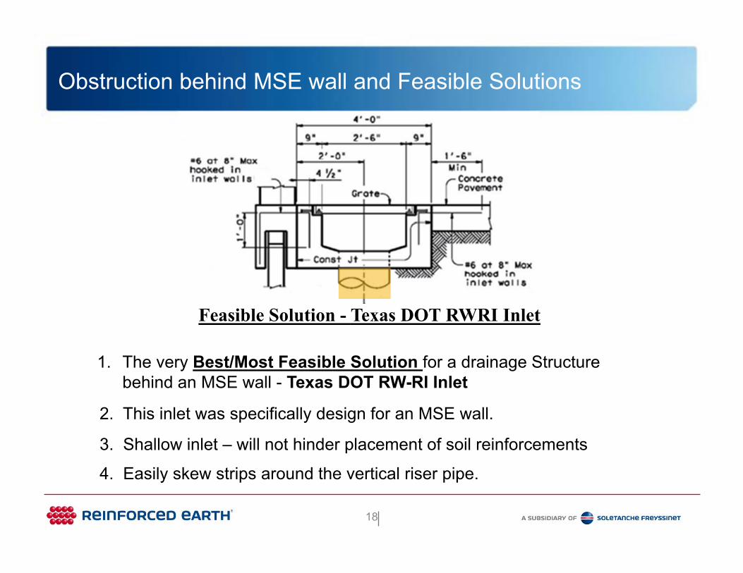
Feasible Solution - Texas DOT RWRI Inlet
1. The very Best/Most Feasible Solution for a drainage Structure behind an MSE wall - Texas DOT RW-RI Inlet
2. This inlet was specifically design for an MSE wall.
3. Shallow inlet – will not hinder placement of soil reinforcements
4. Easily skew strips around the vertical riser pipe.
18

Obstruction behind MSE wall and Feasible Solutions
Box Culvert
Avoid Skewed Box Culvert
1. Creates an acute corner next the Box culvert
2. Special Backfill required 2. Difficult to Design and Construct – potential of panel bulging outwards
19
Obstruction behind MSE wall and Feasible Solutions
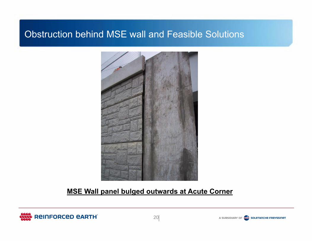
MSE Wall panel bulged outwards at Acute Corner
20

Obstruction behind MSE wall and Feasible Solutions
Feasible solution
2. Alternatively, Box Culvert 25-degree maximum skew angle to MSE Wall.
Box Culvert
Box Culvert
1. Box Culvert perpendicular to MSE Wall.
21

Obstruction behind MSE wall and Feasible Solutions
Shafts behind MSE Walls
22

Obstruction behind MSE wall and Feasible Solutions
3. Limit Size of Shaft diameter toallow placement of the soil reinforcements.
Drilled Shafts behind the MSE wall
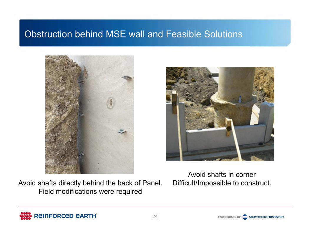
1. Avoid shafts directly behind the back of the panel.
2. Avoid shafts in the corner
Avoid
23
Obstruction behind MSE wall and Feasible Solutions
Avoid shafts directly behind the back of Panel.Field modifications were required
Avoid shafts in corner Difficult/Impossible to construct.
24

Obstruction behind MSE wall and Feasible Solutions
Avoid Large Diameter Shafts/Closely Spaced Shafts.Difficult to construct and cannot attach soil reinforcement to the panel
25

Obstruction behind MSE wall and Feasible Solutions
Feasible Solutions
1. Locate the shaft to achieve a 15-degree skew angle
3. Limit the size of shaft.2. Do not locate shaft in the corner
26

Obstruction behind MSE wall and Feasible Solutions
Feasible Solutions
1. Maintain at least a min.clearance of 1’-6” in all directions
2. Max. skew angle = 30degrees with the necessaryreview and modifications.
27

Obstruction behind MSE wall and Feasible Solutions
Phase Line Construction
28

Obstruction behind MSE wall and Feasible Solutions
Plan View – Phase Line Construction
Most Feasible Solution Construct the temporary MSE wall Perpendicular to
the permanent MSE Wall
Phase 1
TemporaryMSE wire wall
PermanentMSE wall
Phase 1 Phase 2
29

Obstruction behind MSE wall and Feasible Solutions
1. The temporary wire wall could be supplied by a different wall supplier.
Phase Line Construction
2. Concern - non-galvanized Soil reinforcements making contact with the galvanized soil reinforcement.Permanent
MSE Wall
Temporary MSE wire wall with Metallic soil reinforcements
Areas of Concern for overlapping Metallic Soil reinforcements:
30

Obstruction behind MSE wall and Feasible Solutions
PermanentMSE Wall
Temporary MSE wire wall with Geosynthetic soil reinforcements
Areas of Concern for overlapping Metallic & Geosynthetic Soil reinforcement:
1. Two different types of soil reinforcement –metal is inextensible vs geosynthetic is extensible – can cause issues.
2. Depending on the type of geosyntheticreinforcement, the wire wall can bulgeoutward, which is normal, however thiscan cause issue with the permanentprecast wall panel.
31

Obstruction behind MSE wall and Feasible Solutions
Phase Line Construction Issues with Geosynthetic soil reinforcement bulging causing the permanent panels to move horizontally.
32
Obstruction behind MSE wall and Feasible Solutions
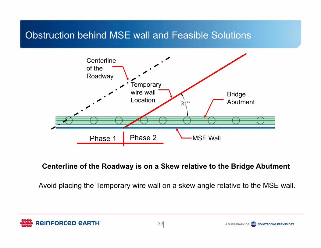
Centerline of the Roadway is on a Skew relative to the Bridge Abutment
Avoid placing the Temporary wire wall on a skew angle relative to the MSE wall.
MSE Wall
Bridge Abutment
Centerlineof the Roadway
Phase 1 Phase 2
Temporary wire wallLocation
33

Obstruction behind MSE wall and Feasible Solutions
Phase 1
PermanentMSE Wall
TemporaryMSE wire wall
Phase 1 is not an issue
34

Obstruction behind MSE wall and Feasible Solutions
Phase 2 has Design and Construction Challenges
35
Phase 1 Phase 2
TemporaryMSE wire wall
PermanentMSE Wall
Challenges
1. An acute corner is formed between the Temporary MSE wire wall and permanent MSE wall (Yellow shade)
2. Permanent Soil reinforcement cannot be extended the full length to reinforce the soil (Green Shade).
3. Need pressure relief wall to remove the horizontal load off the acute corner – basically the Temporary wall becomes a permanent MSE wall
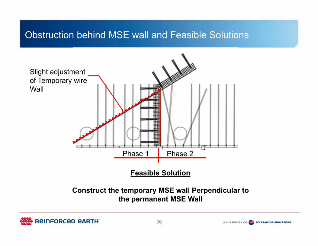
Obstruction behind MSE wall and Feasible Solutions
Feasible Solution
Construct the temporary MSE wall Perpendicular to the permanent MSE Wall
Phase 1 Phase 2
Slight adjustmentof Temporary wireWall
36

Obstruction behind MSE wall and Feasible Solutions
Conclusion
This presentation is being presented to convey the most feasible solutions for the most common obstructions located behind MSE walls.
These solutions could then be considered by the owner’s engineers when developing the contract plans for the owner.
The goal would be to eliminate difficult design and construction issues, potential field problems, and provide an overall better design of the MSE wall for the owner.
37

Obstruction behind MSE wall and Feasible Solutions
Conclusion
Keep in mind, the wall supplier and the contractor are not part of the development of the contract plans. Therefore, they are not part of the initial project planning.
So, it is vital that a careful review and consideration of the proposed feasible solutions for MSE walls be considered during the project planning stage.
If proper coordination among various entities involved can be achieved, then it makes it possible to achieve optimum designs with respect to reinforcement reconfiguration around obstructions found within reinforced fill.
38

Questions
Obstruction behind MSE wall and Feasible Solutions
David L. Hutchinson, P.E.
Director of Engineering The Reinforced Earth Company
817-680-7820
39