octal plug-in accessory power supply - steven … · model apsis - octal plug-in accessory power...
TRANSCRIPT

PROVIDES . . .+12 VDC “HELPER” SUPPLY FOR LOAD SHARING WITHUNREGULATED COUNTER SYSTEMS WITH UNUSUAL SENSORAND ACCESSORY LOADS, OR . . .
“STAND-ALONE” APPLICATIONS FOR POWERING SENSORSAND ACCESSORIES
MODEL APS - OCTAL PLUG-IN ACCESSORY POWER SUPPLY
TYPICAL CONNECTION DIAGRAM
DIMENSIONS In inches (mm)
OUTPUT VOLTS/CURRENT REGULATION CURVE
ORDERING INFORMATION
Bulletin No. APS-F
Drawing No. LP0042
Released 9/06
Tel +1 (717) 767-6511
Fax +1 (717) 764-0839
www.redlion.net
DESCRIPTIONThe Model APS is an unregulated +12 VDC supply designed to load share
when connected in parallel with internal power supplies of many Red LionControls Counters and Rate Indicators. It can also be used as a general purpose“Stand-alone” power supply to power other control circuits, sensors andaccessories. The APS is furnished for 115 VAC or 230 VAC, ±10%, 50/60 Hzprimary supply. Operating temperature range is -20° to +50°C. Output currentis per regulation curve.
MODEL NO. DESCRIPTION PART NUMBER
SKT1
APS01
Base Mount 8-pin Octal Socket
115 VAC Accessory Power Supply
SKT10000
APS01000
--
APS02
DIN Rail 8-pin Socket
230 VAC Accessory Power Supply
SKTDIN00
APS02000
Courtesy of Steven Engineering, Inc.-230 Ryan Way, South San Francisco, CA 94080-6370-Main Office: (650) 588-9200-Outside Local Area: (800) 258-9200-www.stevenengineering.com

These industrial relays have a mechanical lifeexpectancy in excess of 10 million cycles, and are bothUL and CSA recognized.
RELAY SPECIFICATIONSCOIL: 12 VDC Coil - 120 Ω ±10%,
Rated +12 VDC @ 100 mA.115 VAC Coil - 2250 Ω ±10%,Rated 115 VAC @ 52 mA.
CONTACTS: 10 A @ 115 and 230 VAC(1/6 HP @ 115 V, 1/3 HP @ 230 VAC)
OPERATING TIMES:Energize - 30 msec max.De-energize - 30 msec max.Operating times do not include bounce time(approx. 3 msec).
OPERATING TEMPERATURE RANGE:-45° to +60°C
ELECTRICAL LIFE: In excess of 100,000 operations@ rated load.
WEIGHT: 3 oz (85.1 g)
Mating sockets sold separately. See Ordering Information.
PLUG-IN RELAYS PROVIDED FOREASY SERVICING & MAINTENANCE
ACCESSORY PLUG-IN RELAY
CONTACTS SHOWN IN DE-ENERGIZEDPOSITION
ORDERING INFORMATIONDESCRIPTION COIL VOLTAGE PART NUMBER
DPDT Plug-in Relay12 VDC RLY10000115 VAC RLY30000
Base Mount 8-pin Octal Socket SKT10000DIN Rail 8-pin Socket SKTDIN00
LIMITED WARRANTYThe Company warrants the products it manufactures against defects in materials and workmanshipfor a period limited to two years from the date of shipment, provided the products have been stored,handled, installed, and used under proper conditions. The Company’s liability under this limitedwarranty shall extend only to the repair or replacement of a defective product, at The Company’soption. The Company disclaims all liability for any affirmation, promise or representation withrespect to the products.The customer agrees to hold Red Lion Controls harmless from, defend, and indemnify RLC againstdamages, claims, and expenses arising out of subsequent sales of RLC products or productscontaining components manufactured by RLC and based upon personal injuries, deaths, propertydamage, lost profits, and other matters which Buyer, its employees, or sub-contractors are or may beto any extent liable, including without limitation penalties imposed by the Consumer Product SafetyAct (P.L. 92-573) and liability imposed upon any person pursuant to the Magnuson-Moss WarrantyAct (P.L. 93-637), as now in effect or as amended hereafter.No warranties expressed or implied are created with respect to The Company’s products except thoseexpressly contained herein. The Customer acknowledges the disclaimers and limitations containedherein and relies on no other warranties or affirmations.
Red Lion Controls
20 Willow Springs Circle
York PA 17406
Tel +1 (717) 767-6511
Fax +1 (717) 764-0839
Red Lion Controls AP
31, Kaki Bukit Road 3,
#06-04/05 TechLink
Singapore 417818
Tel +65 6744-6613
Fax +65 6743-3360
Red Lion Controls BV
Basicweg 11b
NL - 3821 BR Amersfoort
Tel +31 (0) 334 723 225
Fax +31 (0) 334 893 793
Courtesy of Steven Engineering, Inc.-230 Ryan Way, South San Francisco, CA 94080-6370-Main Office: (650) 588-9200-Outside Local Area: (800) 258-9200-www.stevenengineering.com
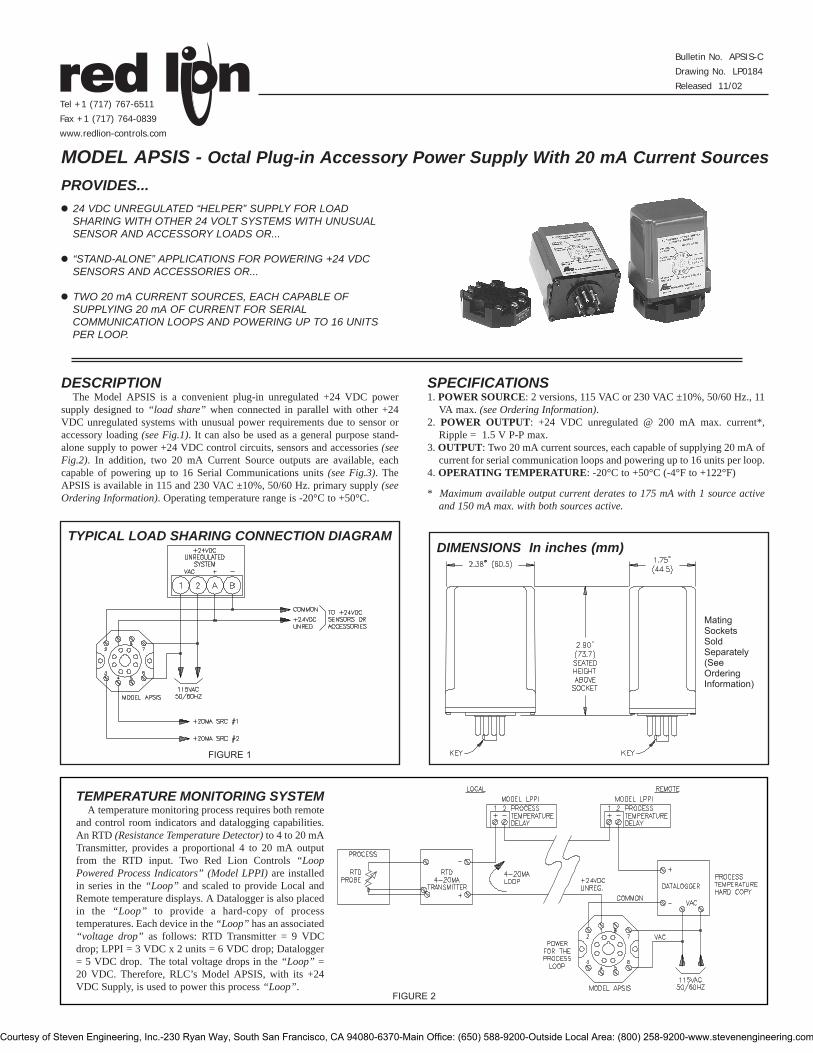
PROVIDES...! 24 VDC UNREGULATED “HELPER” SUPPLY FOR LOAD
SHARING WITH OTHER 24 VOLT SYSTEMS WITH UNUSUALSENSOR AND ACCESSORY LOADS OR...
! “STAND-ALONE” APPLICATIONS FOR POWERING +24 VDCSENSORS AND ACCESSORIES OR...
! TWO 20 mA CURRENT SOURCES, EACH CAPABLE OFSUPPLYING 20 mA OF CURRENT FOR SERIALCOMMUNICATION LOOPS AND POWERING UP TO 16 UNITSPER LOOP.
DESCRIPTIONThe Model APSIS is a convenient plug-in unregulated +24 VDC power
supply designed to “load share” when connected in parallel with other +24VDC unregulated systems with unusual power requirements due to sensor oraccessory loading (see Fig.1). It can also be used as a general purpose stand-alone supply to power +24 VDC control circuits, sensors and accessories (seeFig.2). In addition, two 20 mA Current Source outputs are available, eachcapable of powering up to 16 Serial Communications units (see Fig.3). TheAPSIS is available in 115 and 230 VAC ±10%, 50/60 Hz. primary supply (seeOrdering Information). Operating temperature range is -20°C to +50°C.
SPECIFICATIONS1. POWER SOURCE: 2 versions, 115 VAC or 230 VAC ±10%, 50/60 Hz., 11
VA max. (see Ordering Information).2. POWER OUTPUT: +24 VDC unregulated @ 200 mA max. current*,
Ripple = 1.5 V P-P max.3. OUTPUT: Two 20 mA current sources, each capable of supplying 20 mA of
current for serial communication loops and powering up to 16 units per loop.4. OPERATING TEMPERATURE: -20°C to +50°C (-4°F to +122°F)
* Maximum available output current derates to 175 mA with 1 source activeand 150 mA max. with both sources active.
MODEL APSIS - Octal Plug-in Accessory Power Supply With 20 mA Current Sources
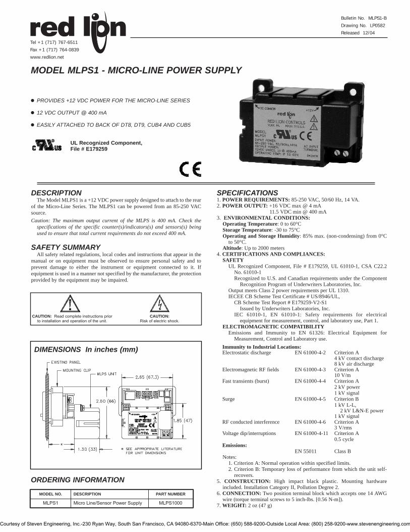
TYPICAL LOAD SHARING CONNECTION DIAGRAMDIMENSIONS In inches (mm)
MatingSocketsSoldSeparately(SeeOrderingInformation)
FIGURE 1
TEMPERATURE MONITORING SYSTEMA temperature monitoring process requires both remote
and control room indicators and datalogging capabilities.An RTD (Resistance Temperature Detector) to 4 to 20 mATransmitter, provides a proportional 4 to 20 mA outputfrom the RTD input. Two Red Lion Controls “LoopPowered Process Indicators” (Model LPPI) are installedin series in the “Loop” and scaled to provide Local andRemote temperature displays. A Datalogger is also placedin the “Loop” to provide a hard-copy of processtemperatures. Each device in the “Loop” has an associated“voltage drop” as follows: RTD Transmitter = 9 VDCdrop; LPPI = 3 VDC x 2 units = 6 VDC drop; Datalogger= 5 VDC drop. The total voltage drops in the “Loop” =20 VDC. Therefore, RLC’s Model APSIS, with its +24VDC Supply, is used to power this process “Loop”.
FIGURE 2
Bulletin No. APSIS-C
Drawing No. LP0184
Released 11/02
Tel +1 (717) 767-6511
Fax +1 (717) 764-0839
www.redlion-controls.com
Courtesy of Steven Engineering, Inc.-230 Ryan Way, South San Francisco, CA 94080-6370-Main Office: (650) 588-9200-Outside Local Area: (800) 258-9200-www.stevenengineering.com

PROCESS MONITORINGSYSTEM
8 Apollo Thermocouples (APLTC) and 8GEMINIs, all with isolated 20 mA CurrentLoop Serial Communications, monitor andcontrol processes within a plant. All units,which are located in different areas of theplant, are tied together in series in two“Loops” (one Transmit Tx, the otherReceive Rx) and are connected to a CentralComputer located in another area of theplant. Since there are more than 7, and nomore than 16 units in the “Loop”, theAPSIS +20 mA Current Source Outputs areused to power each “Loop”. (Both ApolloThermocouple and Gemini units can powerup to 7 units in a “Loop” when using theirinternal 20 mA sources. However, theirsources may not be tied together to powermore than 7 units.) Each unit is assigned adifferent address number and the same Baudrate (see appropriate APLTC or Gemini datasheet). An application program is writtenwhich allows the Central Computer to sendand retreive data from any APLTC orGemini.
FIGURE 3
OUTPUT VOLTS/CURRENT
*Unregulated output +(2) 20 mA currentsources (if used).
ORDERING INFORMATIONPART NUMBERS FOR
MODEL NO. DESCRIPTION AVAILABLE SUPPLY VOLTAGES230 VAC 115 VAC
APSIS Accessory Power Supply- Current Source APSIS010 APSIS000Base Mount, 8-Pin Octal Socket SKT10000Din Rail Mount, 8-Pin Octal Socket SKTDIN00
Courtesy of Steven Engineering, Inc.-230 Ryan Way, South San Francisco, CA 94080-6370-Main Office: (650) 588-9200-Outside Local Area: (800) 258-9200-www.stevenengineering.com
! PROVIDES +12 VDC POWER FOR THE MICRO-LINE SERIES
! 12 VDC OUTPUT @ 400 mA
! EASILY ATTACHED TO BACK OF DT8, DT9, CUB4 AND CUB5
DESCRIPTIONThe Model MLPS1 is a +12 VDC power supply designed to attach to the rear
of the Micro-Line Series. The MLPS1 can be powered from an 85-250 VACsource.Caution: The maximum output current of the MLPS is 400 mA. Check the
specifications of the specific counter(s)/indicators(s) and sensors(s) beingused to ensure that total current requirements do not exceed 400 mA.
SAFETY SUMMARYAll safety related regulations, local codes and instructions that appear in the
manual or on equipment must be observed to ensure personal safety and toprevent damage to either the instrument or equipment connected to it. Ifequipment is used in a manner not specified by the manufacturer, the protectionprovided by the equipment may be impaired.
MODEL MLPS1 - MICRO-LINE POWER SUPPLY
DIMENSIONS In inches (mm)
SPECIFICATIONS1. POWER REQUIREMENTS: 85-250 VAC, 50/60 Hz, 14 VA.2. POWER OUTPUT: +16 VDC max @ 4 mA
11.5 VDC min @ 400 mA3. ENVIRONMENTAL CONDITIONS:
Operating Temperature: 0 to 60°CStorage Temperature: -30 to 75°COperating and Storage Humidity: 85% max. (non-condensing) from 0°C
to 50°C.Altitude: Up to 2000 meters
4. CERTIFICATIONS AND COMPLIANCES:SAFETY
UL Recognized Component, File # E179259, UL 61010-1, CSA C22.2No. 61010-1Recognized to U.S. and Canadian requirements under the Component
Recognition Program of Underwriters Laboratories, Inc. Output meets Class 2 power requirements per UL 1310.IECEE CB Scheme Test Certificate # US/8946/UL,
CB Scheme Test Report # E179259-V2-S1Issued by Underwriters Laboratories, Inc.
IEC 61010-1, EN 61010-1: Safety requirements for electricalequipment for measurement, control, and laboratory use, Part 1.
ELECTROMAGNETIC COMPATIBILITYEmissions and Immunity to EN 61326: Electrical Equipment for
Measurement, Control and Laboratory use.
Notes:1. Criterion A: Normal operation within specified limits.2. Criterion B: Temporary loss of performance from which the unit self-
recovers.5. CONSTRUCTION: High impact black plastic. Mounting hardware
included. Installation Category II, Pollution Degree 2.6. CONNECTION: Two position terminal block which accepts one 14 AWG
wire (torque terminal screws to 5 inch-lbs. [0.56 N-m]).7. WEIGHT: 2 oz (47 g)
CAUTION: Read complete instructions priorto installation and operation of the unit.
CAUTION: Risk of electric shock.
Bulletin No. MLPS1-B
Drawing No. LP0582
Released 12/04
Tel +1 (717) 767-6511
Fax +1 (717) 764-0839
www.redlion.net
MODEL NO. DESCRIPTION PART NUMBER
MLPS1 Micro Line/Sensor Power Supply MLPS1000
ORDERING INFORMATION
UL Recognized Component,File # E179259
Class BEN 55011Emissions:
0.5 cycle
Criterion A3 V/rms Criterion A
EN 61000-4-6
EN 61000-4-11
RF conducted interference
Voltage dip/interruptions
1 kV L-L, Criterion BEN 61000-4-5Surge 1 kV signal2 kV powerCriterion AEN 61000-4-4Fast transients (burst)
1 kV signal2 kV L&N-E power
10 V/mCriterion AEN 61000-4-3Electromagnetic RF fields8 kV air discharge4 kV contact dischargeCriterion AEN 61000-4-2Electrostatic discharge
Immunity to Industrial Locations:
Courtesy of Steven Engineering, Inc.-230 Ryan Way, South San Francisco, CA 94080-6370-Main Office: (650) 588-9200-Outside Local Area: (800) 258-9200-www.stevenengineering.com
INSTALLATION ENVIRONMENTThe unit should be installed in a location that does not exceed the
maximum operating temperature and provides good air circulation. Placingthe unit near devices that generate excessive heat should be avoided.
Installation ProcedureThe MLPS1 is shipped with all the necessary hardware to mount to the
rear of an installed Micro-Line unit. Refer to the instructions that correspondto your Micro-Line unit for proper installation.
TROUBLESHOOTINGFor further technical assistance, contact technical support at the appropriate
company numbers listed.
Red Lion Controls
20 Willow Springs Circle
York PA 17402
Tel +1 (717) 767-6511
Fax +1 (717) 764-0839
Red Lion Controls AP
31, Kaki Bukit Road 3,
#06-04/05 TechLink
Singapore 417818
Tel +65 6744-6613
Fax +65 6743-3360
Red Lion Controls BV
Basicweg 11b
NL - 3821 BR Amersfoort
Tel +31 (0) 334 723 225
Fax +31 (0) 334 893 793
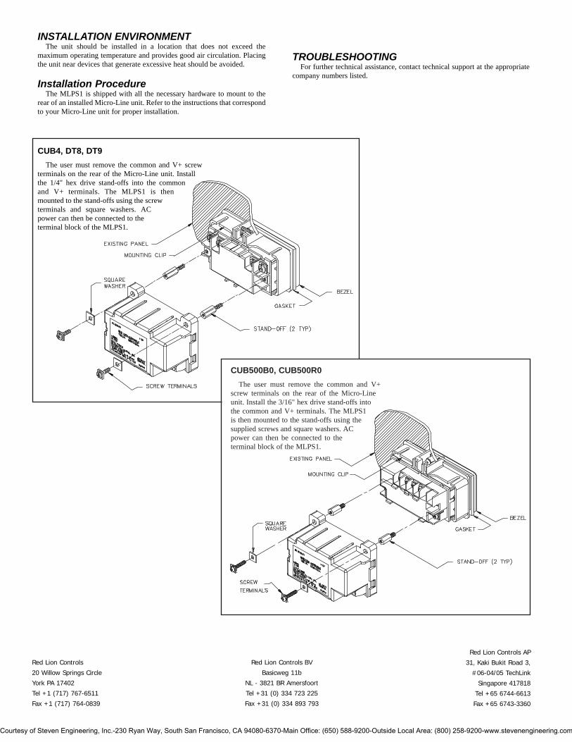
CUB4, DT8, DT9The user must remove the common and V+ screw
terminals on the rear of the Micro-Line unit. Installthe 1/4" hex drive stand-offs into the commonand V+ terminals. The MLPS1 is thenmounted to the stand-offs using the screwterminals and square washers. ACpower can then be connected to theterminal block of the MLPS1.
CUB500B0, CUB500R0The user must remove the common and V+
screw terminals on the rear of the Micro-Lineunit. Install the 3/16" hex drive stand-offs intothe common and V+ terminals. The MLPS1is then mounted to the stand-offs using thesupplied screws and square washers. ACpower can then be connected to theterminal block of the MLPS1.
Courtesy of Steven Engineering, Inc.-230 Ryan Way, South San Francisco, CA 94080-6370-Main Office: (650) 588-9200-Outside Local Area: (800) 258-9200-www.stevenengineering.com

PROVIDES +24 VDC POWER FOR THE MICRO-LINE SERIES
24 VDC OUTPUT @ 200 mA
EASILY ATTACHED TO BACK OF DT8, DT9, CUB4 AND CUB5
DESCRIPTIONThe Model MLPS2 is a +24 VDC power supply designed to attach to the rear
of the Micro-Line Series. The MLPS2 can be powered from an 85-250 VACsource.Caution: The maximum output current of the MLPS2 is 200 mA. Check the
specifications of the specific counter(s)/indicators(s) and sensors(s) beingused to ensure that total current requirements do not exceed 200 mA.
SAFETY SUMMARYAll safety related regulations, local codes and instructions that appear in the
manual or on equipment must be observed to ensure personal safety and toprevent damage to either the instrument or equipment connected to it. Ifequipment is used in a manner not specified by the manufacturer, the protectionprovided by the equipment may be impaired.
MODEL MLPS2 - 24 VDC MICRO-LINE POWER SUPPLY
DIMENSIONS In inches (mm)
SPECIFICATIONS1. POWER REQUIREMENTS: 85-250 VAC, 50/60 Hz, 14 VA.2. POWER OUTPUT: +24 VDC ±10% @ 200 mA3. ENVIRONMENTAL CONDITIONS:
Operating Temperature: 0 to 60°CStorage Temperature: -30 to 75°COperating and Storage Humidity: 85% max. (non-condensing) from 0°C
to 50°C.Altitude: Up to 2000 meters
4. CERTIFICATIONS AND COMPLIANCES:SAFETY
IEC 61010-1, EN 61010-1: Safety requirements for electrical equipmentfor measurement, control, and laboratory use, Part 1.
ELECTROMAGNETIC COMPATIBILITYEmissions and Immunity to EN 61326: Electrical Equipment for
Measurement, Control and Laboratory use.
Notes:1. Criterion A: Normal operation within specified limits.2. Criterion B: Temporary loss of performance from which the unit self-
recovers.5. CONSTRUCTION: High impact black plastic. Mounting hardware
included. Installation Category II, Pollution Degree 2.6. CONNECTION: Two position terminal block which accepts one 14 AWG
wire (torque terminal screws to 5 inch-lbs. [0.56 N-m]).7. WEIGHT: 2 oz (47 g)
Bulletin No. MLPS2-X
Drawing No. LP0741
Effective 1/08
Tel +1 (717) 767-6511
Fax +1 (717) 764-0839
www.redlion.net
MODEL NO. DESCRIPTION PART NUMBER
MLPS2 MLPS2000
ORDERING INFORMATION
Class BEN 55011Emissions:
0.5 cycle
Criterion A3 V/rms Criterion A
EN 61000-4-6
EN 61000-4-11
RF conducted interference
Voltage dip/interruptions
1 kV L-L, Criterion BEN 61000-4-5Surge 1 kV signal2 kV powerCriterion AEN 61000-4-4Fast transients (burst)
1 kV signal2 kV L&N-E power
10 V/mCriterion AEN 61000-4-3Electromagnetic RF fields8 kV air discharge4 kV contact dischargeCriterion AEN 61000-4-2Electrostatic discharge
Immunity to Industrial Locations:
24 VDC Micro Line/Sensor Power Supply
CAUTION: Risk of Danger.Read complete instructions prior to
installation and operation of the unit.
CAUTION: Risk of electric shock.
Courtesy of Steven Engineering, Inc.-230 Ryan Way, South San Francisco, CA 94080-6370-Main Office: (650) 588-9200-Outside Local Area: (800) 258-9200-www.stevenengineering.com

INSTALLATION ENVIRONMENTThe unit should be installed in a location that does not exceed the
maximum operating temperature and provides good air circulation. Placingthe unit near devices that generate excessive heat should be avoided.
Installation ProcedureThe MLPS2 is shipped with all the necessary hardware to mount to the
rear of an installed Micro-Line unit. Refer to the instructions that correspondto your Micro-Line unit for proper installation.
TROUBLESHOOTINGFor further technical assistance, contact technical support at the appropriate
company numbers listed.
CUB5The user must remove the common and V+ screw
terminals on the rear of the Micro-Line unit. Installthe 3/16" hex drive stand-offs into the common andV+ terminals. The MLPS2 is then mounted to thestand-offs using the supplied screws and squarewashers. AC power can then be connected tothe terminal block of the MLPS2.
CUB4, DT8, DT9The user must remove the common and V+ screw
terminals on the rear of the Micro-Line unit. Installthe 1/4" hex drive stand-offs into the common andV+ terminals. The MLPS2 is then mounted to thestand-offs using the screw terminals and squarewashers. AC power can then be connected tothe terminal block of the MLPS2.
Red Lion Controls
20 Willow Springs Circle
York PA 17406
Tel +1 (717) 767-6511
Fax +1 (717) 764-0839
Red Lion Controls AP
Unit 101, XinAn Plaza
Building 13, No.99 Tianzhou Road
ShangHai, P.R. China 200223
Tel +86 21 6113-3688
Fax +86 21 6113-3683
Red Lion Controls BV
Printerweg 10
NL - 3821 AD Amersfoort
Tel +31 (0) 334 723 225
Fax +31 (0) 334 893 793
Courtesy of Steven Engineering, Inc.-230 Ryan Way, South San Francisco, CA 94080-6370-Main Office: (650) 588-9200-Outside Local Area: (800) 258-9200-www.stevenengineering.com
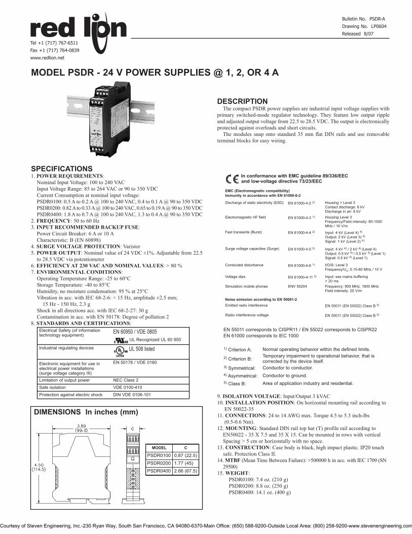
DESCRIPTIONThe compact PSDR power supplies are industrial input voltage supplies with
primary switched-mode regulator technology. They feature low output rippleand adjusted output voltage from 22.5 to 28.5 VDC. The output is electronicallyprotected against overloads and short circuits.
The modules snap onto standard 35 mm flat DIN rails and use removableterminal blocks for easy wiring.
SPECIFICATIONS1. POWER REQUIREMENTS:
Nominal Input Voltage: 100 to 240 VACInput Voltage Range: 85 to 264 VAC or 90 to 350 VDCCurrent Consumption at nominal input voltage: PSDR0100: 0.5 A to 0.2 A @ 100 to 240 VAC, 0.4 to 0.1 A @ 90 to 350 VDCPSDR0200: 0.82 Ato 0.33 A@ 100 to 240 VAC, 0.65 to 0.19 A@ 90 to 350 VDCPSDR0400: 1.8 A to 0.7 A @ 100 to 240 VAC, 1.3 to 0.4 A @ 90 to 350 VDC
2. FREQUENCY: 50 to 60 Hz3. INPUT RECOMMENDED BACKUP FUSE:
Power Circuit Breaker: 6 A or 10 ACharacteristic: B (EN 60898)
4. SURGE VOLTAGE PROTECTION: Varistor5. POWER OUTPUT: Nominal value of 24 VDC ±1%. Adjustable from 22.5
to 28.5 VDC via potentiometer6. EFFICIENCY AT 230 VAC AND NOMINAL VALUES: > 80 %7. ENVIRONMENTAL CONDITIONS:
Operating Temperature Range: -25 to 60°C Storage Temperature: -40 to 85°CHumidity, no moisture condensation: 95 % at 25°CVibration in acc. with IEC 68-2-6: < 15 Hz, amplitude ±2.5 mm;
15 Hz - 150 Hz, 2.3 gShock in all directions acc. with IEC 68-2-27: 30 gContamination in acc. with EN 50178: Degree of pollution 2
8. STANDARDS AND CERTIFICATIONS:EN 55011 corresponds to CISPR11 / EN 55022 corresponds to CISPR22EN 61000 corresponds to IEC 1000
9. ISOLATION VOLTAGE: Input/Output 3 kVAC10. INSTALLATION POSITION: On horizontal mounting rail according to
EN 50022-3511. CONNECTIONS: 24 to 14 AWG max. Torque 4.5 to 5.3 inch-lbs
(0.5-0.6 Nm).12. MOUNTING: Standard DIN rail top hat (T) profile rail according to
EN50022 - 35 X 7.5 and 35 X 15. Can be mounted in rows with verticalSpacing > 5 cm or horizontally with no space.
13. CONSTRUCTION: Case body is black, high impact plastic. IP20 touchsafe. Protection Class II.
14. MTBF (Mean Time Between Failure): >500000 h in acc. with IEC 1709 (SN29500)
15. WEIGHT:PSDR0100: 7.4 oz. (210 g)PSDR0200: 8.8 oz. (250 g)PSDR0400: 14.1 oz. (400 g)
MODEL PSDR - 24 V POWER SUPPLIES @ 1, 2, OR 4 A
DIMENSIONS In inches (mm)
Bulletin No. PSDR-A
Drawing No. LP0604
Released 8/07
Tel +1 (717) 767-6511
Fax +1 (717) 764-0839
www.redlion.net
Industrial regulating devices
Electrical Safety (of informationtechnology equipment)
EN 50178 / VDE 0160
Limitation of output powerSafe isolation
NEC Class 2VDE 0100-410
Protection against electric shock DIN VDE 0106-101
1) Criterion A: Normal operating behavior within the defined limits.
2) Criterion B: Temporary impairment to operational behavior, that iscorrected by the device itself.
3) Symmetrical: Conductor to conductor.4) Asymmetrical: Conductor to ground.5) Class B: Area of application industry and residential.
EN 61000-4-11 2)
I/O/S: Level 3Frequency/Uo: 0.15-80 MHz / 10 V
Discharge of static electricity (ESD)
In conformance with EMC guideline 89/336/EECand low-voltage directive 73/23/EEC
Electromagnetic HF field
EN 55011 (EN 55022) Class B 5)
EN 55011 (EN 55022) Class B 5)
ENV 50204Simulation mobile phones
Emitted radio interference
Radio interference voltage
Input: see mains buffering > 20 ms
Voltage dips
EN 61000-4-6 1)Conducted disturbance
EN 61000-4-5 2)Surge voltage capacities (Surge)
EN 61000-4-4 2)Fast transients (Burst)
EN 61000-4-3 1)
Housing > Level 3Contact discharge: 8 kVDischarge in air: 8 kV
EN 61000-4-2 2)
Frequency: 900 MHz, 1800 MHzField intensity: 20 V/m
Noise emission according to EN 50081-2
EMC (Electromagnetic compatibility)Immunity in accordance with EN 61000-6-2
Input: 4 kV (Level 4) 4)
Output: 2 kV (Level 3) 4)
Signal: 1 kV (Level 2) 4)
Housing Level 3Frequency/Field intensity: 80-1000MHz / 10 V/m
Input: 4 kV 4) / 2 kV 4) (Level 4)Output: 0.5 kV 4) / 0.5 kV 3) (Level 1)Signal: 0.5 kV 4) (Level 1)
EN 60950 / VDE 0805
MODEL C
PSDR0100PSDR0200 1.77 (45)PSDR0400 2.66 (67.5)
0.87 (22.5)
UL Recognized UL 60 950
UL 508 listed C USULR
LISTED
Electronic equipment for use inelectrical power installations (surge voltage category III)
Courtesy of Steven Engineering, Inc.-230 Ryan Way, South San Francisco, CA 94080-6370-Main Office: (650) 588-9200-Outside Local Area: (800) 258-9200-www.stevenengineering.com
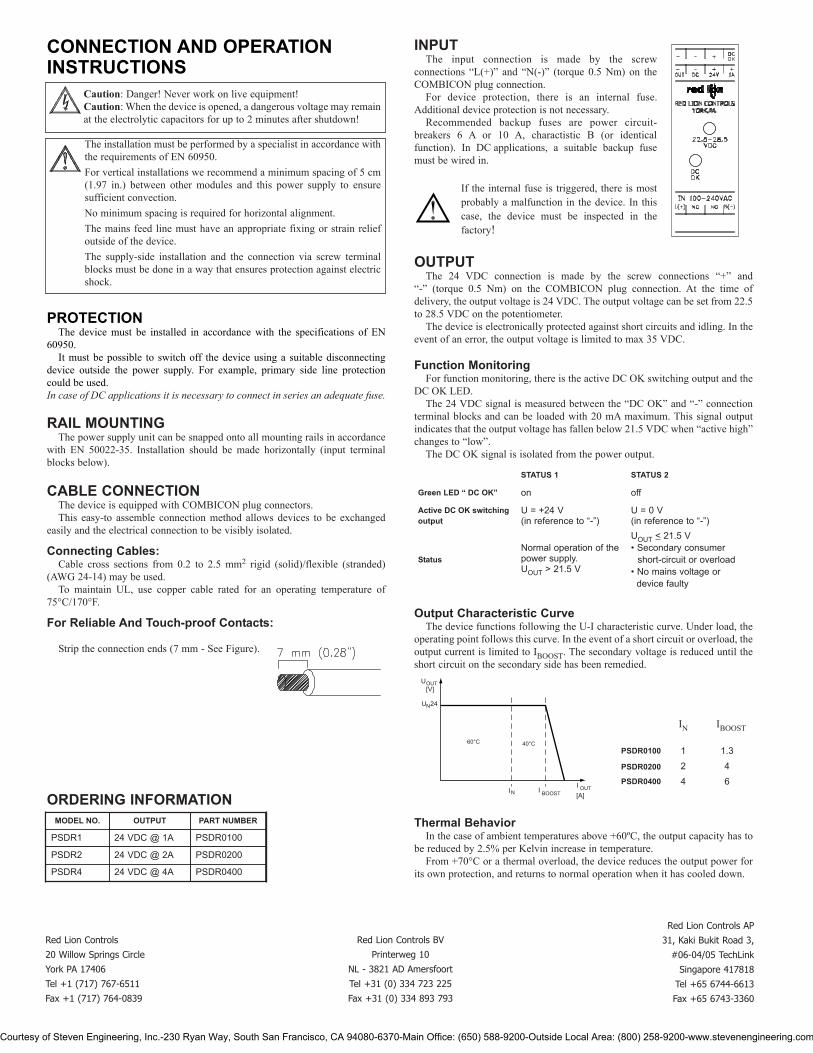
CONNECTION AND OPERATIONINSTRUCTIONS
PROTECTIONThe device must be installed in accordance with the specifications of EN
60950.It must be possible to switch off the device using a suitable disconnecting
device outside the power supply. For example, primary side line protectioncould be used.In case of DC applications it is necessary to connect in series an adequate fuse.
RAIL MOUNTINGThe power supply unit can be snapped onto all mounting rails in accordance
with EN 50022-35. Installation should be made horizontally (input terminalblocks below).
CABLE CONNECTIONThe device is equipped with COMBICON plug connectors.This easy-to assemble connection method allows devices to be exchanged
easily and the electrical connection to be visibly isolated.
Connecting Cables:Cable cross sections from 0.2 to 2.5 mm2 rigid (solid)/flexible (stranded)
(AWG 24-14) may be used.To maintain UL, use copper cable rated for an operating temperature of
75°C/170°F.
For Reliable And Touch-proof Contacts:
Strip the connection ends (7 mm - See Figure).
INPUTThe input connection is made by the screw
connections “L(+)” and “N(-)” (torque 0.5 Nm) on theCOMBICON plug connection.
For device protection, there is an internal fuse.Additional device protection is not necessary.
Recommended backup fuses are power circuit-breakers 6 A or 10 A, charactistic B (or identicalfunction). In DC applications, a suitable backup fusemust be wired in.
If the internal fuse is triggered, there is mostprobably a malfunction in the device. In thiscase, the device must be inspected in thefactory!
OUTPUTThe 24 VDC connection is made by the screw connections “+” and
“-” (torque 0.5 Nm) on the COMBICON plug connection. At the time ofdelivery, the output voltage is 24 VDC. The output voltage can be set from 22.5to 28.5 VDC on the potentiometer.
The device is electronically protected against short circuits and idling. In theevent of an error, the output voltage is limited to max 35 VDC.
Function MonitoringFor function monitoring, there is the active DC OK switching output and the
DC OK LED.The 24 VDC signal is measured between the “DC OK” and “-” connection
terminal blocks and can be loaded with 20 mA maximum. This signal outputindicates that the output voltage has fallen below 21.5 VDC when “active high”changes to “low”.
The DC OK signal is isolated from the power output.
Output Characteristic Curve The device functions following the U-I characteristic curve. Under load, the
operating point follows this curve. In the event of a short circuit or overload, theoutput current is limited to IBOOST. The secondary voltage is reduced until theshort circuit on the secondary side has been remedied.
Thermal BehaviorIn the case of ambient temperatures above +60ºC, the output capacity has to
be reduced by 2.5% per Kelvin increase in temperature.From +70°C or a thermal overload, the device reduces the output power for
its own protection, and returns to normal operation when it has cooled down.
Caution: Danger! Never work on live equipment!Caution: When the device is opened, a dangerous voltage may remainat the electrolytic capacitors for up to 2 minutes after shutdown!
The installation must be performed by a specialist in accordance withthe requirements of EN 60950.For vertical installations we recommend a minimum spacing of 5 cm(1.97 in.) between other modules and this power supply to ensuresufficient convection.No minimum spacing is required for horizontal alignment.The mains feed line must have an appropriate fixing or strain reliefoutside of the device.The supply-side installation and the connection via screw terminalblocks must be done in a way that ensures protection against electricshock.
ORDERING INFORMATION
STATUS 1 STATUS 2
Green LED “ DC OK” on off
Active DC OK switchingoutput
U = +24 V(in reference to “-”)
U = 0 V(in reference to “-”)
StatusNormal operation of thepower supply.UOUT > 21.5 V
UOUT < 21.5 V• Secondary consumer
short-circuit or overload• No mains voltage or
device faulty
U[V]
U 24
60°C 40°C
I I[A]
OUT
N
I OUTBOOSTN
OUTPUT
PSDR1 24 VDC @ 1A PSDR0100
PSDR2 24 VDC @ 2A PSDR0200
PSDR4 24 VDC @ 4A PSDR0400
PART NUMBERMODEL NO.
1 1.3
PSDR0200 2 4PSDR0400 4 6
PSDR0100
IBOOSTIN
Red Lion Controls
20 Willow Springs Circle
York PA 17406
Tel +1 (717) 767-6511
Fax +1 (717) 764-0839
Red Lion Controls AP
31, Kaki Bukit Road 3,
#06-04/05 TechLink
Singapore 417818
Tel +65 6744-6613
Fax +65 6743-3360
Red Lion Controls BV
Printerweg 10
NL - 3821 AD Amersfoort
Tel +31 (0) 334 723 225
Fax +31 (0) 334 893 793
Courtesy of Steven Engineering, Inc.-230 Ryan Way, South San Francisco, CA 94080-6370-Main Office: (650) 588-9200-Outside Local Area: (800) 258-9200-www.stevenengineering.com

1
ALLOWS CUB COUNTERS & DITAKTACHOMETERS TO OPERATE WITH:
2-WIRE PROXIMITY SENSORS,
ROTARY PULSE GENERATORS,
LOGIC MAGNETIC PICKUPS,
MEASURING WHEEL LENGTH SENSORS,
RATE MULTIPLIERS,
4-INPUT ANTI-COINCIDENCE SUMMERS,
CLOCK OSCILLATOR MODULES,
-- AND MANY OTHER SENSORS, CIRCUITS ANDACCESSORIES
* PSMA intended for use with CUB 1, 2, and 4 Counters andDitak 5, 6, and 7 Tachometers.
DESCRIPTIONCub Counters and Ditak Tachometers are basically self-powered devices and
do not have built-in capability for powering electronic sensors or accepting highlevel sensor outputs. The PSMA provides a convenient plug-in answer to thoseapplications requiring electronic sensors or accessories for pulse input to CubCounters or Ditak Tachometers.
The PSMA is available in 115 VAC and 230 VAC primary power inputversions, and delivers regulated D.C. voltage for sensors and accessories. Thesignal conditioning amplifier can accept NPN or PNP Open Collector Inputs, or2-Wire Proximity Sensor Inputs.
The signal conditioning amplifier supplies two separate outputs, one fordirect drive to the H.S. Input of Cub Counters, and the other for direct driveinput to the PSM Input of the Ditak 5 or Input to the Ditak 6 or 7. A ”pulsestretcher” is used in the circuit that provides the output drive to Cub Counters(Terminal 4). This stretcher allows the PSM to accept 50 µsec input pulses,standard on some Red Lion Controls’ sensors and accessories, and expand it tothe 100 µsec pulse, as required by the Cub Counters. The Ditak output(Terminal 8)is not pulse stretched, allowing this output to continue functioningto the full 10 KHz limit of the Ditak.
SPECIFICATIONS1. POWER SOURCE: 2 versions, for 115 VAC ±10% 50/6 0Hz, or 230 VAC
±10% 50/60 Hz. (See Ordering Information.)2. POWER OUTPUT TO SENSORS OR ACCESSORIES: 12 VDC
regulated ±5%, 100 mA max.3. INPUT SIGNAL: (Terminal 3) NPN Open Collector (sink), PNP Open
Collector(source), or 2-wire Input. Built-in 3.3 K resistor (Terminal 5)canbe jumper connected for pull-up, pull-down, or left unconnected as required.Input Schmidt trigger levels as shown on BLOCK DIAGRAM.
4. OUTPUTS: (Terminal 4) Bi-polar drive to H.S. Input of Cub Counterssupplies 100 µsec negative going logic pulse (switches from +3 to 0 volts)inresponse to a trailing (negative going)edge of the input pulse. This outputwill drive up to 3 Cub Counters in parallel.(Terminal 8) NPN Loaded Collector to drive PSM-input of Ditak 5 and Inputof Ditak 6. The output voltage on this terminal is in phase with the inputsignal going into Terminal 3. The high level of this voltage will be clampedto 6.2V by the zener diode in the Ditak. This output can drive up to 3 Ditakunits. For Cub 4 products, use the Ditak output of the PSMA.
5. OPERATING FREQUENCY: 0 to 5000 cps with Cub Counters;0 to 10,000 cps with Ditaks.
MODEL PSMA POWER SUPPLY & INTERFACE MODULEPROVIDES POWER FOR SENSORS & ACCESSORIES WITH SIGNAL
CONDITIONING FOR INPUT TO CUB COUNTERS* & DITAK TACHOMETERS *
BLOCK DIAGRAM (TOP VIEW OF SOCKET)
NOTES1. Inputs and Outputs are referenced to COMMON, on Terminal 2.2. This Power Supply is regulated and cannot be parallel connected with
+12 V outputs from other Red Lion Controls counters or tachometers.
INTERNATIONAL HEADQUARTERS EUROPEAN HEADQUARTERS20 Willow Springs Circle, York, Pa. 17402, (717) 767-6511 FAX: (717) 764-0839 892 Plymouth Road, Slough, Berkshire SL1 4LPWeb site- http://www.redlion-controls.com E-mail- [email protected] ENGLAND +44 1753 696888 FAX: +44 1753 696339
RED LION CONTROLS
BULLETIN NO. PSMA-CDRAWING NO. LP0002REVISED 9/97
Courtesy of Steven Engineering, Inc.-230 Ryan Way, South San Francisco, CA 94080-6370-Main Office: (650) 588-9200-Outside Local Area: (800) 258-9200-www.stevenengineering.com
2
MODEL NO. DESCRIPTION PART NUMBER
PSMA Power Supply & Interface Module (less socket), 115 VAC PSMA1000Power Supply & Interface Module (less socket), 230 VAC PSMA2000
- Base Mount, 8-Pin Octal Socket SKT10000- Din Rail Mount, 8-Pin Octal Socket SKTDIN00
ORDERING INFORMATION
DIMENSIONS “In inches (mm)”
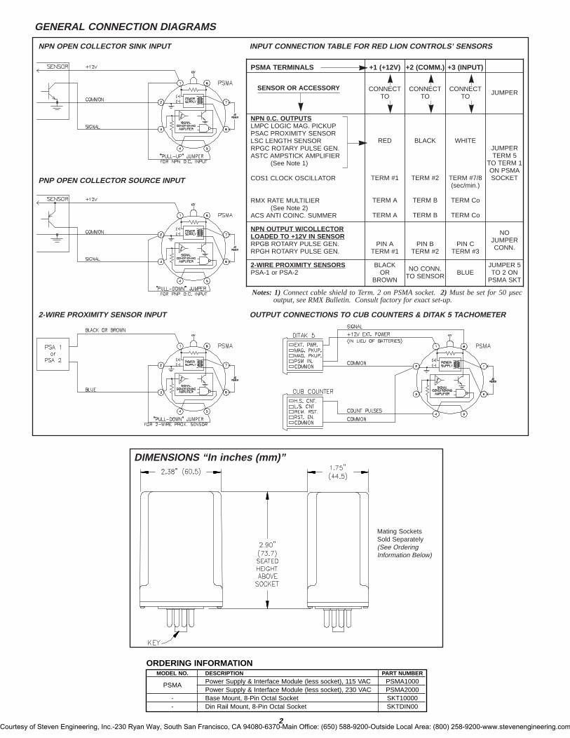
NPN OPEN COLLECTOR SINK INPUT INPUT CONNECTION TABLE FOR RED LION CONTROLS’ SENSORS
PNP OPEN COLLECTOR SOURCE INPUT
Notes:1) Connect cable shield to Term. 2 on PSMA socket. 2) Must be set for 50 µsecoutput, see RMX Bulletin. Consult factory for exact set-up.
2-WIRE PROXIMITY SENSOR INPUT OUTPUT CONNECTIONS TO CUB COUNTERS & DITAK 5 TACHOMETER
GENERAL CONNECTION DIAGRAMS
PSMA TERMINALS +1 (+12V) +2 (COMM.) +3 (INPUT)
SENSOR OR ACCESSORY CONNECTTO
CONNECTTO
CONNECTTO JUMPER
NPN 0.C. OUTPUTSLMPC LOGIC MAG. PICKUPPSAC PROXIMITY SENSORLSC LENGTH SENSORRPGC ROTARY PULSE GEN.ASTC AMPSTICK AMPLIFIER
(See Note 1)
COS1 CLOCK OSCILLATOR
RMX RATE MULTILIER(See Note 2)
ACS ANTI COINC. SUMMER
RED
TERM #1
TERM A
TERM A
BLACK
TERM #2
TERM B
TERM B
WHITE
TERM #7/8(sec/min.)
TERM Co
TERM Co
JUMPERTERM 5
TO TERM 1ON PSMASOCKET
NPN OUTPUT W/COLLECTORLOADED TO +12V IN SENSORRPGB ROTARY PULSE GEN.RPGH ROTARY PULSE GEN.
PIN ATERM #1
PIN BTERM #2
PIN CTERM #3
NOJUMPERCONN.
2-WIRE PROXIMITY SENSORSPSA-1 or PSA-2
BLACKOR
BROWN
NO CONN.TO SENSOR BLUE
JUMPER 5TO 2 ON
PSMA SKT
Mating SocketsSold Separately(See OrderingInformation Below)
Courtesy of Steven Engineering, Inc.-230 Ryan Way, South San Francisco, CA 94080-6370-Main Office: (650) 588-9200-Outside Local Area: (800) 258-9200-www.stevenengineering.com