oeechcraft. duke - weeblyuniklmiatamm.weebly.com/uploads/3/9/6/2/39623959/beechcraft_duke... ·...
TRANSCRIPT

Oeechcraft.DUKE
MODEL 60 (P-4 thru P-126 except P-123)MODEL A60 (P-123, P-127 thru P-246)
MODEL B60 (P-247 and after)
MAINTENANCE MANUAL
PIN 60-590001-25issued: November 2, 1973 PIN 60-590001-25A18
Supersedes: 60-590001-58 Revised: November 20, 1987

PUBLISHED BYCOMMERCIAL PUBLICATIONS
BEECH AIRCRAFT CORPORATIONWICHITA, KANSAS 67201
U. S. A.
Rechcraft Me NGeneral Aviation
AliagilleenCompany menuiscourersAasociaison

Title Page.................................................November 20, 1987"A" Page................................................................A18"B" Page................................................................A18
LOGOF REVISIONS
PART NUMBER DATE CHAPTERAFFECTED
60-590001-25 November 2, 1973 - Original
60-590001-25A1 August 16, 1974 61, 71
60-590001-25A2 May 30, 1975 Intro, 5, 12, 21, 25, 27,30, 32, 36, 56, 61, 71,91, Insp.
60-590001-25A3 October 27, 1975 Intro, 7, 12, 22, 28, 30,32, 53, 57, 91
60-590001-25A4 October 19, 1977 12, 24, 25, 28, 30, 32,33, 61, 73, 79
60-590001-25A5 May 12, 1978 Intro, 5, 11, 12, 20, 23,24, 30
60-590001-25A6 September 14, 1979 Intro, 5, 27
60-590001-25A7 February 22, 1980 Intro, 5, 12, 21, 57, 91
60-590001-25A8 April 18, 1980 Intro, 11, 12, 20, 25, 33,52
60-590001-9A9 August 15, 1980 Intro, 25, 38
60-590001-25A10 November 28, 1980 560-590001-25A11 February 27, 1981 55, 57
60-590001-25A12 April 2, 1981 5, 57, 91
60-590001-25A13 June 21, 1982 5, 30
NOTE: A list of the effective pages will be found in the front of each chapter.
Basic publications are assigned a part number which appears on the title page with the date of the issue. Subsequentrevisions are identified by the addition of a revision code atter the part number. A1 after a part number denotes the firstrevision to the basic publication. A2 the second. etc. Occasionally. it is necessary to completely reissue and reprint apublication for the purpose o1 obsoleting a previous issue and outstanding revisions thereto. As these replacement reissuesare made. the code will âlso change to the next successive letter of the alphabet at each issue For example. B tor the firstreissue. C tor the second reissue. etc.
When ordering a handbook. give the basic number. and the reissue code when applicable, il a complete up-to-date publicationis desired Should only revision pages be requifed. give the basic number and revision code for the particular set of revisionpages you desire.
A
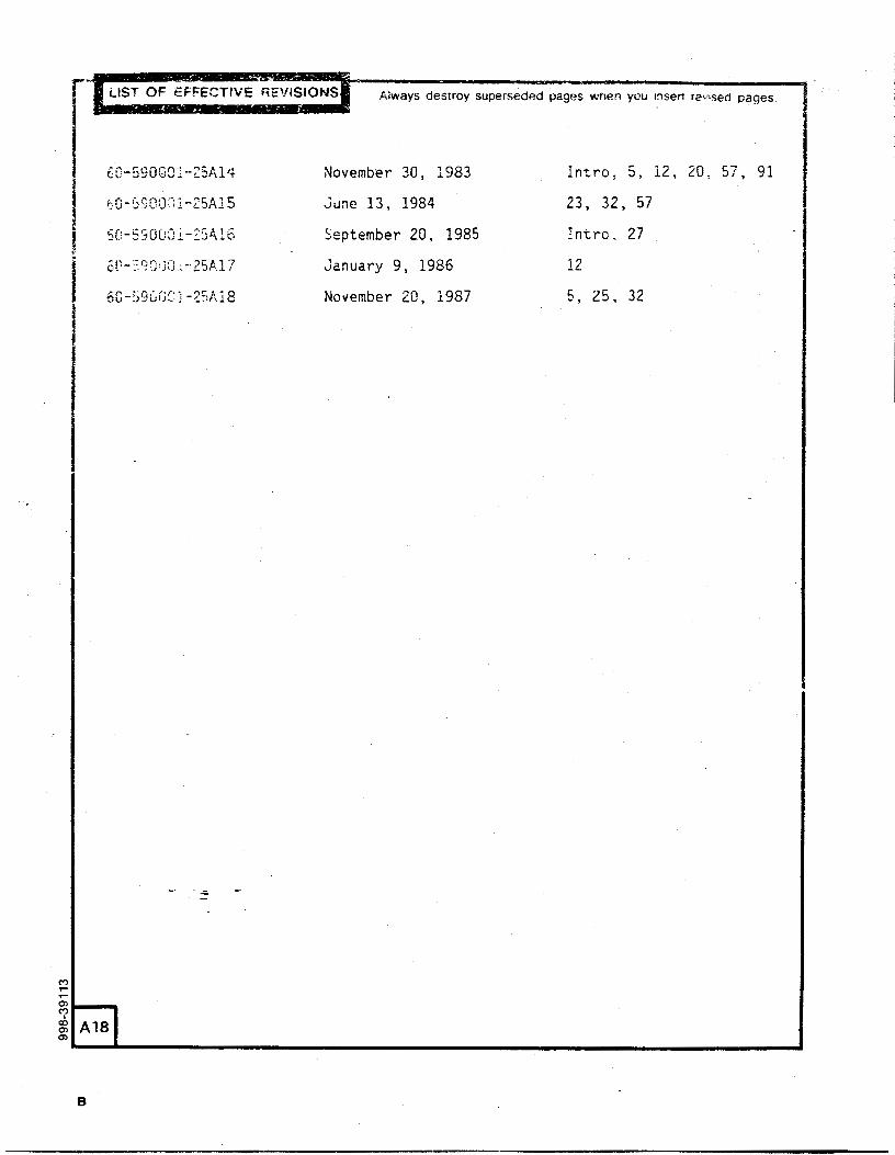
Always destroy superseded pages when you sert revised pages
60-590001-25A14 November 30, 1983 Intro. 5, 12, 20, 57, 91
0-590001-25A15 June 13, 1984 23, 32, 57
60-590Ü01-25416 September 20, 1985 Intro, 27
öf-59000 25A17 January 9, 1986 12
60-59600 25A18 November 20, 1987 5, 25, 32
1B

BEECHCRAFTDUKE60SERIES
MAINTENANŒMANUAL
INTRODUCTION
LIST OF PAGE EFFECTIVITY
CHAPTERSECTIONSUBJECT PAGE DATE
INTRODUCTION-EFFECTIVITY 1 Sep 20/85
INTRODUCTION 1 Nov 30/832 Sep 20/853 Nov 30/834 Nov30/835 Nov 30/836 Nov30/837 Nov 30/838 Nov30/839 Nov 30/83
10 Nov 30/8310A Nov 30/8311 Aug 15/8012 Aug 15/8013 Aug 15/8014 Aug 15/8015 Aug 15/8016 Aug 15/8017 Aug 15/8018 Aug 15/8019 Aug 15/8020 Aug 15/80
"END"
INTRODUCTION-EFFECTIVITYPage 1
A16 Sep 20/85
BEECHCRAFTDUKE60SERIES
MAINTENANCEMANUAL
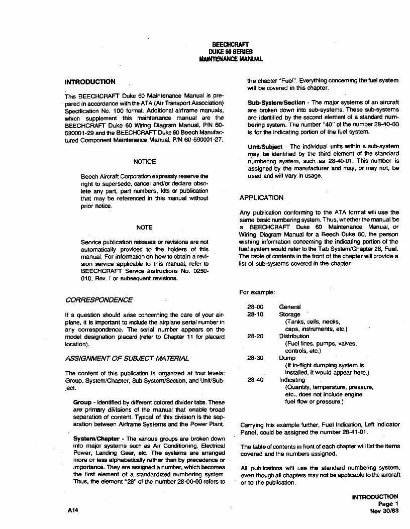
INTRODUCT10N the chapter "Fuel". Everything conceming the fuel systemwill be covered in this chapter.
This BEECHCRAFT Duke 60 Maintenance Manual is pre-
pared in accordance with theATA (AirTransport Association) Sub-System/Section - The major systems of an aircraftSpecification No. 100 format. Additional airframe manuals, are broken down into sub-systems. These sub-systemswhich supplement this maintenance manual are the are identified by the second element of a standard num-BEECHCRAFT Duke 60 Wiring Diagram Manual, P/N 60- bering system. The number "40" ofthe number 28-40-00590001-29 and the BEECHCRAFT Duke 60 Beech Manufac- is for the indicating portion of the fuel system.tured Component Maintenance Manual, PIN 60-590001-27.
Unit/Subject - The individual units within a sub-systemmay be identified by the third element of the standard
NOTICE numbering system, such as 28-40-01. This number isassigned by the manufacturer and may, or may not, be
Beech Aircraft Corporation expressly reserve the used and will vary in usage.right to supersede, cancel and/or declare obso-lete any part, part numbers, kits or publicationthat may be referenced in this manual without APPLICATIONprior notice.
Any publication conformingto the ATA format will use thesame basic numbering system. Thus, whether the manual be
NOTE a BEECHCRAFT Duke 60 Maintenance Manual, orWiring Diagram Manual for a Beech Duke 60, the person
Service publication reissues or revisions are not wishing information conceming the indicating portion of theautomatically provided to the holders of this fuel system would refer to the Tab System/Chapter 28, Fuel.manual. For information on how to obtain a revi- The table ofcontents in the front of the chapter willprovide asion service applicable to this manual, refer to list of sub-systems covered in the chapter.BEECHCRAFT Service Instructions No. 0250-010, Rev. I or subsequent revisions.
For example:CORRESPONDENCE
28-00 GeneralIf a question should arise conceming the care of your air- 28-10 Storageplane, it is important to include the airplane serial number in (Tanks, cells, necks,any correspondence. The serial number appears on the caps, instruments, etc.)model designation placard (refer to Chapter 11 for placard 28-20 Distributionlocation). (Fuel lines, pumps, valves,
controls, etc.)ASSIGNMENT OF SUB./ECT MATERIAL 28-30 Dump
(If in-flight dumping system isThe content of this publication is organized at four levels: installed, it would appear here.)Group, System/Chapter, Sub-System/Section, and Unit/Sub. 28-40 Indicatingject. (Quantity,temperature, pressure,
etc., does not include engineGroup - Identified by different colored divider tabs. These fuel flow or pressure.)are~ priinary divisions of the manual that enable broadseparation of content. Typical of this division is the sep-aration between Airframe Systems and the Power Plant- Carrying this example further, Fuel Indication, Left Indicator
Panel, could be assigned the number 28-41-01.System/Chapter - Re various groups are broken downinto major systems such as Air Conditioning, Electrical The table of contents in front ofeach chapter will list the itemsPower, Landing Gear, etc. The systems are arranged covered and the numbers assigned.more or less alphabetically rather than by precedence orimportance. Rey are assigned a number,which becomes All publications will use the standard numbering system,the first element of a standardized numbering system- even though all chapters may not be applicabletothe aircraftThus, the element "28" ofthe number 28-00-00 refers to or to the publication.
INTRODUCTIONPage 1
A14 Nov 30/83

BEECHCRAFTDUKE60 SERIES
MAINTENANCEMANUAL
ATA 100.PAGE BLOCK GU/DE current issue of the Publications Price List for aenumeration of the maintenance information available
Following is a guide to the assignment of the blocks of Aerofiche form for order from Beech Aircraft Corporationpages within each System/Chapter. Sub-System/Section,Unit/Subject number in the maintenance manual. ATA 100 INDEX GUIDE
Description and Operation Pages 1 to 100 The following is an ATA-100 System/Chapter, SubTroubleshooting Pages 101 to 200 System/Section Index Guide for use with MaintenanoMaintenance Practices Pages 201 to 300 Manuals, Parts Catalogs, Wiring Diagram Manuals ani
Lomponent Maintenance Manuals as required.The text providing the coverage of the description andoperation ofa system or component would appear on pages WARNINGnumbered consecutively 1 through 100, if needed. Theinformation pertaining to the troubleshooting of this same Useon iy genu ine 8 EECHCR A FT orsystem or component would appear on pages numbered SEECHCRAFT approved parts obtained fromconsecutivelyi01through200,itneeded.Themaintenance BEECHCRAFT approved sources, inpractices information would appear on pages numbered 201 connection with the maintenance and repair ofthrough 300. The word "END" at the bottom of a page Beech airplanes.would.indicate the last page in that block.
Genuine BEECHCRAFT parts are producedand inspected under rigorous procedures to
L/ST OF EFFECTIVE REVIS/ONS insure airworthiness and suitability for use in. Beech airplane applications. Parts purchased
The Log of Effective Revisions following the title page of the from sources other than SEECHCRAFT, evenmanual lists the revisions currently effective for the manual. though outwardly identical in appearance, may
not have had the required tests and inspectionsperformed, may be different in fabrication
LIST OF EFFECTIVE PAGES techniques and materials, and may bedangerous when installed in an airplane.
The List of Effective Pages and the Table of Contents in thefront of each chapter will each start with page 1 and be Salvaged airplane parts, reworked partsnumbered consecutively, thereafter, as necessary. obtained from non-BEECHCRAFT approved
sources, or parts, components, or structuralALPHABETICAL INDEX assemblies, the service history of which is
unknown or cannot be authenticated, may haveAn alphabetical index, as part of the introduction, is been subjected to unacceptable stresses orprovided as an assistance in locating the desired temperatures or have other hidden damage, notinformation. The alphabetical index provides the chapter discemible through routine visual or usualand sub-chapter in which any given information may be nondestructive testing techniques. This mayfound. Reference to the Table of Contents in the front of the render the part, component or structuralindicated chapter will provide the exact page on which the assembly, even though originallymanufacturedinformation can be found. by BEECHCRAFT, unsuitable and unsafe for
airplane use.MICROFICHE - AEROFICHE
BEECHCRAFT expressly disclaims anyThe General Aircraft Manufacturers Association has responsibility for malfunctions, iailures, damagedeveloped a spec6cation for microfiche and registered the or injury caused by use of non-BEECHCRAFTname Aerofiche for use by all GAMA Members. Consult the approved parts
l NOTE
ftshall be the responsibility ofthe ownerloperatorto ensure that the latest revision of publicationsreferenced in this handbook are utilized during -operation, servicing, and maintenance ofthe air-plane.
INTRODUCT10NPage 2Sep 20/85 A1(

BEECHCRAFTDUKE60 SERIES
MAINTENANCEMANUAL
ATA-100 SYSTEM/CHAPTER INDEX GUIDE
The following chapters are not covered within this Maintenance Manual: 26, 29, 31, 37, 39, 49, 54, 60, 70, 75, 76, 78,and 83
SYSTEM/ SUB-SYSTEM/CHAPTER SECTION TITLE
INTRODUCTION
AIRCRAFT GENERAL
5 TIME LIMITS/MAINTENANCE CHECKS
10 Time Limits20 Scheduled Maintenance Checks
6 DIMENSIONS AND AREAS
7 LIFTING AND SHORING
00 General
8 LEVELINGAND WEIGHING
00 General
9 TOWING AND TAXIING
00 General
10 PARKING AND MOORING
00 General
11 PLACARDS AND MARKINGS
00 General
12 SERVICING
00 General10 Replenishing20 Scheduled Servicing
AIRFRAMESYSTEMS
20 STANDARD PRACTICES-AIRFRAME
00 Standard Practices-Airframe
INTRODUCTIONPage 3
A14 Nov 30/83

BEECHCRAFTDUKE60 SERIES
MAINTENANCEMANUAL
SYSTEM/ SUB-SYSTEMICHAPTER SECTION TITLE
21 AIR CONDITIONING
00 General10 Compression20 Distribution30 Pressurization Control40 Heating50 Cooling
22 AUTOFLIGHT
00 General10 Autopilot (H14)11 Autopilot (New-Matic)
23 COMMUNICATIONS
60 Static Discharging
24 ELECTRIC POWER
00 General30 DC Generation31 DC Generation (Battery)32 DC Generation (Charge Current Detector)40 External Power50 Electrical Load Distribution
25 EQUIPMENT/FURNISHINGS
00 General60 Emergency
26 FIRE PROTECTION
27 FLIGHT CONTROLS
00 General10 Aileron and Tab20 Rudder and Tab30 Elevator and Tab50 Flaps60 Spoiler, Drag Devices and Variable Aerodynamic Fairings70 Gust Lock and Dampener
28 FUEL
00 General10 Storage20 Distribution40 Indicating
INTRODUCTIONPage 4Nov 30/83 A14

BEECHCRAFTDUKE60 SERIES
MAINTENANCEMANUAL
SYSTEM/ SUB-SYSTEMICHAPTER SECTION TITLE
30 ICE AND RAIN PROTECTION
00 General10 Airfoit20 Air Intakes30 Pitot and Static40 Windows and Windshields60 Propellers/Rotors
32 LANDING GEAR
00 General10 Main Gear and Doors20 Nose Gear and Doors30 Extension and Retraction40 Wheels and Brakes50 Steering60 Position and Warning
33 LIGHTS
00 General40 Exterior
34 NAVIGATION
10 Flight Environment Data
35 OXYGEN
00 General
36 PNEUMATIC
00 General
AIRFRAME SYSTEMS
38 WATER/WASTE
30 Waste Disposal
STRUCTURES
51 STRUCTURES
00 General
INTRODUCTIONPage 5
A14 Nov 30/83

BEECHCRAFTDUKE60 SEAIES
MAINTENANCEMANUAL
SYSTEMI SUB-SYSTEM/CHAPTER SECTION TITLE
52 DOORS
00 General10 Passenger/Crew60 Entrance Stairs70 Door Warning
53 FUSELAGE
30 Plates/Skin
55 STABILIZERS
00 General10 Horizontal Stabilizers20 Elevator30 Vertical Stabilizer40 Rudder
56 WINDOWS
00 General10 Flight Compartment20 Cabin
57 WINGS
00 General30 Plates/Skin40 Attach Fittings50 Flight Surfaces
PROPELLERS
61 PROPELLERS
00 General
POWER PLANT
71 POWER PLANT
00 General10 Cowling
72 ENGINE RECIPROCATING
73 ENGINE FUEL AND CONTROL
30 indicating
INTRODUCTIONPage 6Nov 30/83 A14

BEECHCRAFTDUKE60 SERIES
MAINTENANCEMANUAL
SYSTEM/ SUS-SYSTEM/CHAPTER SECTION TITLE
74 IGNITION
00 General10 Electrical Power Supply20 Distribution
77 ENGINE INDICATING
00 General
79 OIL
00 General
80 STARTING
00 General10 Cranking
81 TURBINES
00 General
91 CHARTS
00 Charts
INTRODUCTIOIPage
A14 Nov 30/8
BEECHCRAFTDUKE60 SERIES
MAINTENANCEMANUAL
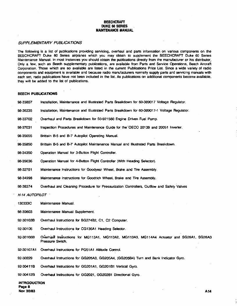
SUPPLEMENTARY PUBLICATIONS
The following is a list of publications providing servicing, overhaul and parts information on various components on theBEECHCRAFT Duke 60 Series airplanes which you may obtain to supplement the BEECHCRAFT Duke 60 SeriesMaintenance Manual. In most instances you should obtain the publications directly from the manufacturer or his distributor.Only a few, such as Beech supplementary publications, are available from Parts and Service Operations, Beech AircraftCorporation. Those which are so available are listed in the current Publications Priœ List. Since a wide variety of radiocomponents and equipment is available and because radio manufacturers normallysupply parts and servicing manuals witheach set, radio publications have not been included in the list. As publications on additional components become available,they will be added to the list of publications.
BEECH PUBLICATIONS
98-33857 installation, Maintenance and illustrated Parts Breakdown for 60-389017 Voltage Regulator.
98-36235 Installation, Maintenance and Illustrated Parts Breakdown for 60-389017-1 Voltage Regulator.
98-33702 Overhaul and Parts Breakdown for 50-921560 Engine Driven Fuel Pump.
98-37031 Inspection Procedures and Maintenanœ Guide for the'OECO 20139 and 20051 Inverter.
98-35655 Brittain B-5 and B-7 Autopilot Operating Manual.
98-35850 Brittain B-5 and B-7 Autopilot Maintenance Manual and illustrated Parts Breakdown.
98-34350 Operation Manual for 3-Button Flight Controller.
98-35636 Operation Manual for 4-Button Flight Controller (With fleading Selector).
98-32751 Maintenance Instructions for Goodyear Wheel, Brake and Tire Assembly.
98-34998 Maintenance Instructions for Goodrich Wheel, Brake and Tire Assembly.
98-36374 Overhaul and Cleaning Procedure for Pressurization Controllers, Outflow and Safety Valves
H-14 AUTOP/LOT
130333C Maintenance Manual.
98-30603 Maintenance Manual Supplement.
92-301038 Overhaul Instructions for BG274B2, C1, C2 Computer.
92-30105 Overhaul Instructions for CG136A1 Heading Selector.
92-301068 Okrh Instructions for MG113A1, MG113A2, MG113A3, MG114A4 Actuator and SG28A1, SG28A3Pressure Switch.
92-30107A1 Overhaul Instructions for PG51A1 Altitude Control.
92-30229 Overhaul Instructions for GG205A3, GG205A4, (GG205B4) Turn and Bank Indicator Gyro.
92-304118 Overhaul Instructions for GG201A1, GG20181 Vertical Gyro.
92-304128 Overhaul Instructions for GG2021, GG202B1 Directional Gyro.
INTRODUCTIONPage 8Nov 30/83 A14

BEECHCRAFTDUKE60 SERIES
MAINTENANCEMANUAL
H-14 AUTOP/LOT (Cont'd.)
98-32523 Overhaul Instructions for MG112A1, MG112B1 Trim Actuator.
98-32839 Overhaul Instructions for CG41781, CG41782 Flight Controller.
VENDOR PUBLICATIONS
ENGINE
Parts Catalog PC-120, Avco Lycoming Division, Williamsport, Pennsylvania. Overhaul Manual 60294-6, Avco LycomingDivision,Williamsport, Pennsylvania. Operator's Manual 60297-13, Avco Lycoming Division,Williamsport, Pennsylvania.
FUEL INJECTION
Operation and Service Manual, Form 15-468, Bendix Corporation, South Bend, Indiana.
PROPELLER
Overhaul Instructions 117B for Hartzell Propeller, Hartzell Propeller Inc., Piqua, Ohio.
Owners Manual 115E for Hartzell HCF3YR2/C7479-2R and Hartzell HCF3YR2F/FC7479B2R Propellers, Hartzell PropellerInc., Piqua, Ohio.
Spinner Assembly Maintenance Instruction Guide, Issued: June 1974, Hartzell Propeller Inc., Piqua, Ohio
Maintenance Handbook for Constant Speed Hydraulic Propeller Governor Type CSSA, Number 33002, Woodward GovernorCompany, Rockford, Illinois.
MAGNETOS
Overhaul Instructions for Bendix S-1200 Series Magnetos, Form L-609, Scintilla Division,Bendix Aviation Corporation, Sidney,New York.
Service Parts List for Bendix S-1200 Series Magnetos, Form L-608, Scintilla Division, Bendix Aviation Corporation, Sidney,New York.
STARTINGMOTOR
Overhaul Instructions, Form OE-A1, Prestolite Company, Toledo, Ohio.
DE/CER DISTRIBUTOR VALVE
Overhaul instructions with Parts Breakdown, Publication Number 38U-2-142, Fluid Power Division, Bendix Aviation Corp.Utica" NefYorki
Operation and Service Instructions, Publication Number 39U-1-810E Fluid Power Division, Bendix Aviation Corp. Utica, NewYork.
ELECTRONICSYNCHRON/ZER
Installation Manual, Bulletin Number 33032A, Woodward Governor Company, Rockford, Illinois.
Propeller Synchronizer for Light Twin Engine Aircraft, Bulletin Number 33049C, Woodward Governor Company, Rockford,Illinois.
INTRODUCTIONPage 9
A14 Nov 30/83

BEECHCRAFTDUKE60 SERIES
MAINTENANCEMANUAL
HYDRAULIC ACCUMULATOR
Maintenance Manual Number 33058, Woodward Govemor Company, Rockford, Illinois.
GENERATOR
Overhaul and Parts Breakdown, Fife 30204, Lear Siegler Inc., Cleveland, Ohio.
BAT7ERY
Operator and Service Manual for Vented-Cell Nickel-Cadmium Battery, GET3593A, General Electric Company, Gainesville,Florida.
Maintenance Manual for Nickel-Cadmium Battery, ABD1100,Gulton Industries, Inc., Metuchen, New Jersey.
Marathon Battery Installation Manua, BA89, Marathon Battery Co., Cold Springs, N.Y.
ELECTRIC PROPELLER DEICER
Installation of Deicer Boots, Report 59-728, B.F. Goodrich Company, Akron, Ohio.
Installation, inspection and Testing of Propeller Deicer System, Report 68-04-708, B,F. Goodrich Company, Akron, Ohio.
HEATER VENT BLOWER
Overhaul instructions for Vane Axial Blower Number M6921N6A, with Motor M3416DA, Dynamic Air Engineering Inc., SantaAna, California.
HEATER
Maintenance Instructions for Janitrol A34D51Aircraft Heater, Publication Number 57083, Janitrol Aero Division, Midland-RossCorporation, Columbus, Ohio.
Maintenance Instructions for Janitrol 52D70 Aircraft Heater ignition Unit, Publication Number 58D42, Janitrol Aero Division,Midland-Aoss Corporation, Columbus, Ohio.
AIR CONDITIONER COMPRESSOR
Series 67 Compressor Service Manual, Form 180.33NM, York Corporation, York, Pennsylvania,
Renewal Parts List, Form 180.33RP, York Corporation, York, Pennsylvania.
OU7FLOW AND SAEETY VALVE
Operation and Maintenance instructions, Report No. 4-268, 15 April 1975, Garrett Airesearch Manufacturing Division, LosAngeles, CA.
EUEL CELLS
Recommended Handling and Storage Procedures for Bladder Type Fuel and Oil Cells, Publication Number FC1473-73,Uniroyal inc., Mishawaka, Indiana 46544.
Repair Procedures for Heated Repairs to Bladder and Self-sealing Fuel Cells, Repair Procedure RK-72, February 3, 1977,Uniroyal, Inc., Mishawaka, Indiana 46544.
INTRODUCTION
Page 10Nov 30/83 A14

BEECHCRAFTDUKE60 SERIES
MAINTENANCEMANUAL
NEWMATIC AUTOP/LOT
B-8 Ground and Flight Check Procedures Manual Number 3957, Brittain Industries, Torrance, Califomia.
LANDING GEAR MOTOR
Component Maintenance Manual with Illustrated Parts List for Landing Gear Motor P/N 27-4 and 27-8, Electro-Mech, Inc.,Wichita, Ks.
BRAKES
Overhaul Information for A22 Brake Shuttle Valve, Publication Number 74456, Hoof Products, Co., Chicago, Illinois.
Overhaul Information for Brake Shuttle Valve, A-SA404, Publication Number 23595, Paramount Machine Co., Stow, Ohio.
EMERGENCY LOG4TOR TRANSMITTER
Operating Instructions for Model CIR-10( ) Emergency Locator Transmitter System, Transmitter P/N TR 70-17,Collins/Communications Components Corporation, Costa Mesa, Califomia.
Operating Instructions for Model C1R-11( ) Emergency Locator Transmitter System, Transmitter P/N TR 70-13;Collins/Communication Components Corporation, Costa Mesa, Califomia.
Owners Manual, Installation and Pilot's Guide P/N 03716-0602 for the Narco ELT 10 Emergency Locator Transmitter, NarcoAvionics, Division of Narco Scientific Industries, Fort Washington, Pennsylvania.
INTRODUCTIONPage 10A
A14 Nov 30/83

BEECNCRAFTDUKE 60 SERIES
MAINTENANCE MANUAL
ALPHABETICAL INDEX
COMPONENT ITEM CHAPTER CHAPTER &OR SYSTEM NAME NAME SUB CHAPTER
AAC GENERATION ELECTRICAL POWER 24-00-00AILERON BALANCING WINGS 57-50-00AILERON CONTROL CABLE INSTALLATION FLIGHT CONTROLS 27-10-00AILERON CONTROL CABLE REMOVAL FLIGHT CONTROLS 27-10-00AILERON CONTROL SYSTEM RIGGING FLIGHT CONTROLS 27-10-00AILERON INSTALLATION FLIGHT CONTROLS 27-10-00AILERON MAINTENANCE WINGS 57-50-00AILERON REMOVAL FLIGHT CONTROLS 27-10-00AILERON SERVO PRESSURE REGULATOR PNEUMATIC 36-00-00AILERON TRIM TAB ACTUATOR INSTALLATION FLIGHT CONTROLS 27-10-00AILERON TRIM TAB ACTUATOR REMOVAL FLIGWT CONTROLS 27-10-00AILERON TRIM TAB CABLE INSTALLATION FLIGHT CONTROLS 27-10-00AILERON TRIM TAB CABLE REMOVAL FLIGHT CONTROLS 27-10-00AILERON TRIM TAB RIGGING FLIGHT CONTROLS 27-10-00AILERON TRIM TAB-CHECKING FREE PLAY FLIGHT CDNTROLS 27-10-00AIR CONOITIONER-CHARGING SERVICING 12-10-00AIR CONOITIONING FUNCTIONAL TEST AIR CONDITIONING 21-50-00AIR CONOITIONING SYSTEM AIR CONDITIONING 21-00-00AIR CONDITIONING SYSTEM SERVICING 12-10-00AIR CONDITIONING SYSTEM CHARGING AIR CONDITIONING 21-50-00AIR SCOOP RIGGING AIR CONDITIONING AIR GONDITIONING 21-50-00AIRPLANE FINISH CARE STANDARD PRACTICES-AIRFRAME20-00-00AIRPLANE FINISH CLEANING & WAKING SERVICING 12-2D-00ALCAL GALIBRATION UNIT ENGINE INDICATING 77-00-00ALTITUDE CONTROLLER INSTALLATION,CABIN AIR CONDITIONING 21-30-00ALTITUOE CONTROLLER REMOVALeCABIN AIR CONDITIONING 21-30-00ASSIST STEP AOJUSTMENT-FDLDED DOORS 52-60-00ASSIST STEP BELL CRANK INSTALLATION DOORS 52-60-00ASSIST STEP BELL CRANK REMOVAL DOORS 52-60-00ASSIST STEP CA6LE INST (P-4 THRU P-509) DOORS 52-60-00ASSIST STEP CABLE INST (P-510 & AFTER) DOORS 52-60-00ASSIST STEP CA6LE REM (P-4 THRU P-509) DOORS 52-60-00ASSIST STEP CABLE REM (P-510 & AFTER) DOORS 52-60-00ASSIST STEP INSTALLATION DOORS 52-60-00ASSIST STEP REMOVAL DOORS 52-60-00ASSIST STEP STRUT ASSY INSTALLATION DOORS 52-60-00ASSIST STEP STRUT ASSY REMOVAL DOORS 52-60-00AUTOPILOT PNEUMATIC SYSTEM AUTO FLIGHT 22-10-00AUTOPILOT REGULATOR-N-14 09EUMATIC 36-00-00AUTOPILOT-H-14 AUTO FLIGHT 22-10-00AUTOPILOT-NEW-MATIC AUTO FLIGHT 22-11-00
BSATT REPL, COLLINS/COMM COMP CORP ELT EQUIPMENT/FURNISHINGS 25-60-00BATTERY ELECTRICAL POWER 24-00-00BATTERY SERVICING 12-20-00BATTERY CAPACITY CHECK ELECTRICAL POWER 24-31-00BATTERY GAPACITY RECONDITIONING ELECTRICAL POWER 24-31-00BATTERY CNARGE CURRENT DETECTOR SYSTEM ELECTRICAL POWER 24-00-00BATTERY CHARGE CURRENT DETECTOR SYSTEM ELECTRICAL POWER 24-32-00BATTERY CHARGING ELECTRICAL POWER 24-31-00BATTERY CLEANING AND INSPECTION ELECTRICAL POWER 24-31-00BAT.TERY CONSTANT CURRENT CHARGING ELECTRICAL POWER 24-31-00BATTERY CONSTANT POTENTIAL CHARGING ELECTRICAL POWER 24-31-00BATTERY ELECTRICAL LEAKAGE CHECK ELECTRIGAL POWER 24-31-00BATTERY ELECTROLYTE LEVEL ADJUSTMENT ELECTRIGAL POWER 24-31-00BATTERY EMERGENGY LOCATOR EQUIPMENT AND FURNISHINGS 25-60-00BATTERY INSTALLATION ELECTRICAL POWER 24-31-00BATTERY MAINTENANCE LOG ELECTRICAL POWER 24-31-00SATTERY MAINTEMANCE PROGRAM ELECTRICAL POWER 24-31-00BATTERY PRE-INSTALLATION INSTRUCTION ELECTRICAL POWER 24-31-00BATTERY RECONOITIONING FREQUENCY ELECTRICAL POWER 24-31-00SATTERY RECONOITIONING PROCEDURE ELECTRICAL POWER 24-31-00BATTERY REMOVAL ELECTRICAL POWER 24-31-00BATTERY REPL, NARCO ELT EQUIPMENT/FURNISHINGS 25-60-00BATTERY STAND-BY CHARGING ELECTRICAL POWER 24-31-00
INTROOUCTIONPAGE 11
AUG 15/80

BEECHCRAFTDUKE 60 SERIES
MAINTENANCE MANUAL
ALPHABETICAL INDEX
COMPONENTITEM CHAPTER CHAPTER SOR SYSTEM NAME NAME SUS CHAPTER
BBRAKE ASSEMBLY LANDING GEAR 32-40-00BRAKE ASSEMBLY INSTALLATION LASOING GEAR 32-40-00BRAKE ASSEMBLY REMOVAL LANDING GEAR 32-40-00BRAKE GRAVIT¥ BLEEDING LAMOING GEAR 32-40-40BRAKE NYORAULIC SYSTEM LANGING GEAR 32-40-00BRAKE MASTER CYLINDER INSTALLATION LANOING GEAR 32-40-00BRAKE MASTER CYLINDER LINKAGE ADJUST LANGING GEAR 32-40-00BRAKE MASTER C¥LINDER REMOVAL LANOING GEAR 32-40-00BRAKE PRESSURE BLEEDING LANDING GEAR 32-40-00BRAKE S¥STEM SERVICING 12-10-00BRAKE SYSTEM BLEE0ING LANDING GEAR 32-40-00BRAKE SYSTEM BLEE0ING-0UAL LAMOING GEAR 32-40-00BRAKE MEAR LIMITS-GOODRICN LANDING GEAR 32-40-00BRAKE WEAR LIMITS-GOOOYEAR LAMUING GEAR 32-40-00
CCABIN ALTITUDE CONTROLLER AOJUSTMENT AIR CONDITIONING 21-30-00CABIN ALTITUOE CONTROLLER FILTER AIR CONOITIONING 21-30-00CABIN ALTITUDE CONTROLLER INSTALLATION AIR"CONDITIONING 21-30-00CABIN ALTITUOE CONTROLLER INSTALLATION AIR.CONOITIONING 21-30-40CABIN ALTITUDE CONTROLLER REMOVAL AIRECOMDITIONING 21-30-00CABIN ALTITUOE CONTROLLER-MANUAL AIRCCONDITIONING 21-30-00CASIN ALTITUOE CONTROLLER-MOTORIZED AIACCONDITIONING 21-30-00CABIN 000R 00045 52-10-00CASIN DOOR INSTALLATION DOGES 52-10-00CABIN 000R LATCH A0JUSTMENT DOORS 52-10-00CABIN DOOR LATCH MECHANISM LUBE DOGRS 52-10-00CABIN DOOR LATCN MECHANISM RIGGING DOGES 52-10-00CABIN DOOR LIGNT SWITCHES DOGRS 52-70-00CASIN 000R REMOVAL DOORS 52-10-00CABIN TEMP SENSORS/CONT RHEO TEST AIR CONDITIONING 21-40-00CABLE TENSION-EFFECT OF TEMP UPON FLIGHT CONTROLS 27-00-00CARRY THROUGH STRUCTURE WINGS 57-00-00CHEMICAL TOILET CLEANING WATER/WASTE 38-30-00COMBUSTION AIR BLOWER INSTALLATION AIR=COMDITIONING 21-40-00CONSUSTION AIR BLOWER REMOVAL AIRiCOMDITIONING 21-40-00COMPRESSION AIACCONDITIONING 21-10-00COMPRESSOR BELT INSTALLATIDN AERCCONDITIONING 21-50-40COMPRESSOR BELT REMOVAL AIR CONDITIONING 21-50-00COMPRESSOR BELT TENSION AOJUSTMENT ATRTCONDITIONING 21-50-00COMPRESSOR BELT TENSION AOJUSIMENT SERVICING 12-10-00COMPRESSOR INSTALLATION AER CONDITIONING 21-50-00COMPRESSOR DIL LEVEL CHECKING SERVICING 12-10-00COMPRESSOR DIL LEVEL CHECKING AER CONDITIONING 21-50-00COMPRESSOR REMOVAL AIR CONOITIONING 21-50-00CONDENSER BLOWER INSTALLATION AER CONOITIONING 21-50-00CONDENSER BLOWER REMOVAL ATR CONDITIONING 21-50-00CONSUMABLE MATERIALS CHARTS 91-00-00CONSUMABLE MATERIALS CHART SERVICING 12-20-00CONTROL COLUMN FCOGNT CONTROLS 27-00-00CONTROL COLUMN $US CABLE INSTALLATION FUEGHΠCONTROLS 27-00-00CONTROL COLUNN BUS CABLE RENOVAL ELEGHT CONTROLS 27-00-00CONTROL COLUMN BUS CABLE RIGGING ERIGHT CONTROLS 27-00-00CONTROLLER INSfALLATIONaCABIN ALTITUOE ABR COMDirIONING 21-30-00CONTR LLEWREMOVALeCABIN ALTITUDE AER CONDITIONING 21-30-00COOLING ARR CONDITIONING 21-50-00COWL FLAP ACTUATOR RIGGING EBRER PLANT 71-10-00COWL FLAP AND ACTUATOR INSTALLATION ROWER PLANT 71-10-00COWL FLAP AND ACTUATOR REMOVAL EGWER PLANT 71-10-00COWLING INSTALLATION ROWER PLANT 71-10-00COWLING REMOVAL POWER PLANT 71-10-00
DDC GENERATION ELECTRICAL POWER 24-00-00OEFUELING-AIRCRAFT EUEL 28-00-00
INTRODUCTIDNPAGE 12AUG 15/80

BEECHCRAFTOUKE 60 SERIES
MAINTENANCE MANUAL
ALPHABETICAL INDEX
COMPDNENT ITEM CHAPTER CHAPTER &OR SYSTEM NAME NAME SUB CHAPTER
DDEICER BOOTS SERVICING 12-20-00DEICER BOOTS-RESURFACING ICE AND RAIN PROTECTION 30-10-00DEICER SYSTEM-AIRFOIL ICE ANO RAIN PROTECTION 30-10-00DIF CONT & SAFETY VALVE ADJUSTMENT AIR CONDITIONING 21-30-00DIF CONT & SAFETY VALVE INSTALLATION AIR CONDITIONIMG 21-30-00DIF CONT & SAFETY VALVE REMOVAL AIR CONDITIONING 21-30-00DIFFERENTIAL CONTROL VALVE AIR CONOITIONING 21-30-00DIMENSIONS-AIRCRAFT DIMENSIONS AND AREAS 06-00-00DISTRIBUTION AIR CONDITIONING 21-20-00
IIELECT TRIM TAB ACT MAG CLUTCH INST FL1GHT CONTROLS 27-3Œ-00ELECT TRIM TAB ACT MAG CLUTCH TEST FLIGHT CONTROLS 27-30-00ELECT TRIM TAB ACT MAG CLUTCH REMOVAL FLIGHT CONTROLS 27-30-00ELECTRIC TRIM TAS ACTUATOR INSTALLATION FLIGHT CONTROLS 27-30-00ELECTRIC TRIM TAB ACTUATOR REMOVAL FLIGHT CONTROLS 27-3Œ-00ELECTRIC TRIM TAS CABLE INSTALLATION FLIGHT CONTROLS 27-30-00ELECTRICAL UTILIZATION LOAD CHART ELECTRICAL POWER 24-50-00ELEVATOR BALAMCING STABILIZERS 55-20-00ELEVATOR CABLE INSTALLATION FLIGHT CONTROLS 27-30-00ELEVATOR CABLE REMOVAL FLIGHT CONTROLS 27-30-00ELEVATOR CONTROL SYSTEM RIGGING FLIGHT CONTROLS 27-30-00ELEVATOR INSTALLATION FLIGHT CONTROLS 27-30-00ELEVATOR REMOVAL FLIGHT CONTROLS 27-30-00ELEVATOR TRIM TAB ACTUATOR INSTALLATION FLIGHT CONTROLS 27-30-00ELEVATOR TRIM TAB ACTUATOR REMOVAL FLIGHT CONTROLS 27-30-00ELEVATOR TRIM TAB CABLE INSTALLATION FLIGHT CONTROLS 27-30-00ELEVATOR TRIM TAB CABLE REMOVAL FLIGHT CONTROLS 27-30-00ELEVATOR TRIM TAB RIGGING FLIGHT CONTROLS 27-30-00ELEVATOR TRIM TAS-CHECKING FREE PLAY FLIGHT CONTROLS 27-30-00ELT BATT REPL, COLLINS/COMM COMP CORP EQUIPMENT/FURNISHINGS 25-60-00ELT BATTERY REPLACEMENT, NARCO EQUIPMENT/FURNISHINGS 25-60-00EMERGENCY LOCATOR.TRANSMITTER EQUIPMENT AND FURNISHIMGS 25-60-00EMPENNAGE STABILIZERS 55-00-00ENGINE AIR INDUCTION SYSTEM TURBINES 81-00-00ENGINE BUILO-UP POWER PLANT 71-00-00ENGINE GRDUND RUNNING ANO WARM-UP POWER PLANT 71-00-00ENGINE IOLE SPEED & MIXTURE ADJUSTMENT POWER PLANT 71-00-00ENGINE INSTALLATION POWER PLANT 71-00-00ENGINE DILS-APPROVED CHARTS 91-00-00ENGINE OILS-APPROVED OIL 79-00-00ENGINE OVERSOOST CONTROL TURBINES 81-00-00ENGINE OVERHAUL ENGINE 72-00-00ENGINE REMOVAL POWER PLANT 71-0Œ-00EQUIPMENTwTEST (PO4 & AFTER) AIR CONDITIONING 21-30-00EVAPORATOR AIR FILTER REPLACEMENT AIR CONDITIONING 21-50-00EVAPORATOR AIR FILTER REPLACEMENT SERVICING 12-10-00EXTERNAL POWER ELECTRICAL POWER 24-40-00EXTERNAL POWER SERVICING 12-20-00
FIBERGLASS CDMPONENTS-REPAIR OF STRUCTURES 51-00-00FIREWALL SHUT-OFF VALVE AIR CONDITIONING 21-10-00FLAP ACTUATOR INSTALLATION FLIGHT CONTROLS 27-50-00FLAP ACTUATOR REMOVAL FLIGHT CONTROLS 27-50-00FLAP CONTROL SYSTEM RIGGING FLIGHT CONTROLS 27-50-00FLAP FUNCTIONAL GROUND TEST FLIGHT CONTROLS 27-50-00FLAP INSTALLATION FLIGHT CONTROLS 27-50-00FLAP MOTOR/GEARBOX INSTALLATION FLIGHT CONTROLS 27-50-00FLAP MOTOR/GEARBOX REMOVAL FLIGHT CONTROLS 27-50-00FLAP POS INO LIGHTS-ADJUST & CHECK FLIGHT CONTROLS 27-50-00FLAP POSITION TRANSMITTER ADJUSTMENT FLIGWf CONTROLS 27-50-00FLAP REMOVAL FLIGHT CONTROLS 27-50-00FLAP TRACK ROLLER INSTALLATION FLIGHT CDNTROLS 27-50-00FLAPS FLIGWT CONTROLS 27-50-00
INTRODUCTIONPAGE 13
AUG 15/80

BEECHCRAFTOUKE 60 SERIES
MAINTENANCE MANUAL
ALPHABETICAL INDEX
COMPONENT ITEM CHAPTER CHAPTER &OR SYSTEM NAME NAME SUB CHAPTER
FFLARE FITTING TOROUE CHART CHARTS 91-00-00FLARED FITTINGS FUEL 28-20-00FLIGHT CONTROLS FLIGHT CONTROLS 27-00-00FUEL BOOST PUMP INSTALLATION FUEL 28-20-00FUEL BOOST PUMP REMOVAL FUEL 25-20-00FUEL BOOST PUMPS FUEL 28-00-00FUEL CELL DRAINS FUEL 28-00-00FUEL CELL FLAPPER VALVE INSP-BAFFLED FUEL 28-10-00FUEL CELL INST-INBOARD LEAOING EDGE FUEL 28-10-00FUEL CELL INST-OUTSOARO LEADING EDGE FUEL 28-10-00FUEL CELL INSTALLATION-BOX SECTION FUEL 28-10-00FUEL CELL INSTALLATION-NAGELLE FUEL 28-10-00FUEL CELL LEAKAGE CHECK FUEL 28-10-00FUEL CELL REMOVAL-BOX SECTION FUEL 28-10-00FUEL CELL REMOVAL-INSD LEAOING EDGE FUEL 28-10-00FUEL CELL REMOVAL-NAGELLE FUEL 28-10-00FUEL CELL REMOVAL-OUTBD LEADING EDGE FUEL 28-10-00FUEL CELL REPAIR-GOODYEAR FUEL 28-10-00FUEL CELL REPAIR-UNIROYAL FUEL 28-10-00FUEL CELL VELCRO TAPE-INST OF FUEL 28-10-00FUEL CELL VENT FLOAT VALVE INSTALLATION FUEL 28-20-00FUEL CELL VENT FLOAT VALVE REMOVAL FUEL 28-20-00FUEL CELL VENT LINE-EXTERNAL rUEL 28-20-00FUEL CELLS FUEL 28-00-00FUEL CELLS-FILLING SERVICING 12-10-00FUEL CROSSFEED FUEL 28-00-00FUEL FILTER5 AND &CREENS-ENGINE SERVICING 12-10-00FUEL FLOW INDICATOR ENGINE FUEL AND CONTROL 73-30-00FUEL GAGING SYSTEM-ADJUST AND TEST FUEL 28-40-00FUEL MANOLING PRACTICES FUEL 28-00-00FUEL PUMP AOJUSTMENT-ENGINE DRIVEN FUEL 28-20-00FUEL PUMP INSTALLATION-ENGINE ORIVEN FUEL 28-20-00FUEL PUMP REMOVAL-ENGINE DRIVEN FUEL 28-20-00FUEL QUANTITY INDICATORS FUEL 28-40-00FUEL SELECT VALVE CONT CABLE REMOVAL FUEL 28-20-00FUEL SELECT VALVE CONT CABLE RIGGING FUEL 28-20-00FUEL SELECT VALVE CONT CABLE INSTALL FUEL 28-20-00FUEL SELECTOR VALVE INSTALLATION FUEL 28-20-00FUEL SELECTOR VALVE REMOVAL FUEL 28-20-00FUEL SYSTEM-ORAINING SERVICING 12-10-00FUEL TRANSMITTER INSTALLATION FUEL 28-40-00FUEL TRANSMITTER REMOVAL FUEL 28-40-00FUSELAGE ACCESS OPENINGS FUSELAGE 53-30-00
GGENERATOR ELECTRICAL POWER 24-00-00GENERATOR BRUSH REPLACEMENT ELECTRICAL POWER 24-30-00GENERATOR CURRENT ADJ-MAXIMUM LOAD ELECTRICAL POWER 2+-30-00GENERATOR INSTALLATION ELECTRICAL POWER 24-30-00GENERATOR PARALLELING ELECTRICAL POWER 24-30-00GENERATOR PARALLELING RHEOSTATS-ADJUST ELECTRICAL POWER 24-30-00GENERATOR PARALLELING-FINAL CHECKS ELECTRICAL POWER 24-30-00GENERATOR REMDVAL ELECTRICAL POWER 24-30-00GENEA&TDR -SYSTEM STABILIZATION ELECTRICAL POWER 24-30-00GENERATOR VOLTAGE ADJUST-MINIMUM LOAD ELECTRICAL POWER 24-30-00GENERATOR VOLTAGE REGULATOR ADJUST ELECTRICAL POWER 24-30-00GUST LOCK FLEGHT CONTROLS 27-70-00GYRO INSTRUMENT PRESSURE REGULATOR PNEUMATIC 36-00-00
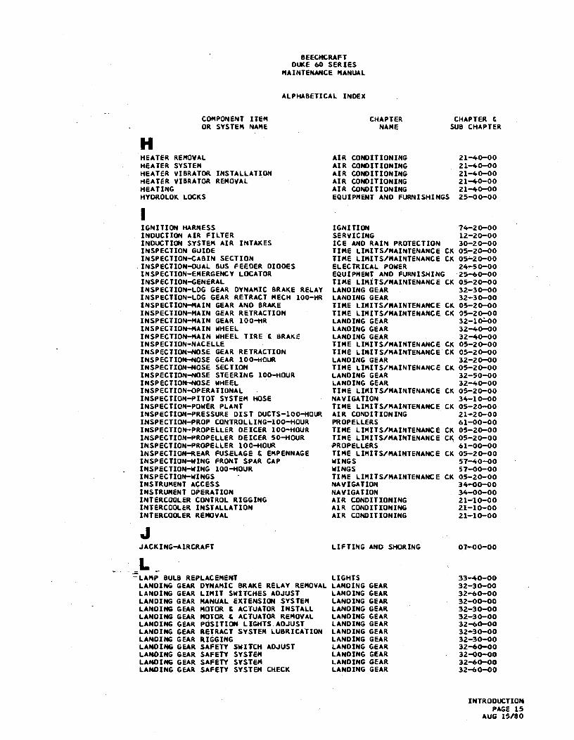
HHEATER CONTRDL SYSTEM AIR CONDITIONING 21-40-00HEATER FUEL PUMP AIR ONDITIONING 21-40-00HEATER IGNITION AIR CONDITIONING 21-40-00HEATER INSTALLATION AIR CONDITIONING 21-40-00HEATER OPERATION AIR CONDITIONING 21-40-00
INTRODUCTIONPAGE 14AUG 15/80
BEECHCRAFTDUKE 60 SERIES
MAINTENANCE MANUAL
ALPMABETICAL INDEX
COMPONENT ITEM CHAPTER CHAPTER &OR SYSTEM NAME NAME SUB CHAPTER
HHEATER REMOVAL AIR CONDITIONING 21-40-00HEATER SYSTER AIR CONDITIONING 21-40-00MEATER VIBRATOR INSTALLATION AIR CONDITIONING 21-40-00HEATER VIBRATOR REMOVAL AIR CONDITIONING 21-40-00HEATING AIR CONDITIONING 21-40-00HYDROLOK LOCKS EQUIPMENT AND FURNISHINGS 25-00-00
IIGNITIDN MARNESS IGNITION 74-20-00INDUCTION AIR FILTER SERVICING 12-20-00INDUCTION SYSTEM AIR INTAKES ICE AND RAIN PROTECTION 30-20-00INSPECTION GUIDE TIME LIMITS/MAINTENANCE CK 05-20-00INSPECTION-CABIN SECTION TIME LIMITS/MAINTENANCE CK 05-20-00INSPECTION-DUAL BUS FEEDER DIODES ELECTRICAL POWER 24-50-00INSPECTION-EMERGENCY LDCATOR EQUIPMENT AND FURNISHING 25,50-00INSPECTION-GENERAL TIME LIMÌTS/MAINTENANCE CK 05-20-00INSPECTION-LOG GEAR DYNAMIC BRAKE RELAY LANDING GEAR 32-30-00INSPECTION-LOG GEAR RETRACT MECH 100-HR LANOING GEAR 32-30-00INSPECTION-MAIN GEAR ANO BRAKE TIME LIMITS/MAINTENANCE CK 05-20-00INSPECTION-MAIN GEAR RETRACTION TIME LIMITS/MAINTENANCE CK 05-20-00INSPECTION-MAIN GEAR 100-HR LANDING GEAR 32-10-00INSPECTION-MAIN WHEEL LANOING GEAR 32-40-00INSPECTION-MAIN WHEEL TIRE & BRAKE LANDING GEAR 32-40-00INSPECTION-NAGELLE TIME LIMITS/MAINTENANCE CK 05-20-00INSPECTION-NOSE GEAR RETRACTION TIME LIMITS/MAINTENANCE CK 05-20-00INSPECTIDM-NOSE GEAR 100-HOUR LANDING GEAR 32-20-00INSPECTION-NOSE SECTION TIME LIMITS/MAINTENANCE CK 05-20-00INSPECTION-NOSE STEERING 100-HOUR LANDING GEAR 32-50-00INSPECTIDM-NOSE WHEEL LANDING GEAR 32-40-00INSPECTION-OPERATIONAL TIME LIMITS/MAINTENANCE CK 05-20-00INSPECTION-PITOT SYSTEM HOSE NAVIGATION 34-10-00INSPECTION-POWER PLANT TIME LIMITS/MAINTENANCE CK 05-20-00INSPECTION-PRESSURE DIST DUCTS-100-HOUR AIR CONDITIONING 21-20-00INSPECTION-PROP CONTROLLING-100-HOUR PROPELLERS 61-00-00INSPECTIOR-PROPELLER DEICER 100-HOUR TIME LIMITS/MAINTENANCE CK 05-20-00INSPECTION-PROPELLER DEICER 50-HOUR TIME LIMITS/MAINTENANCE CK 05-20-00INSPECTION-PROPELLER 100-NOUR PROPELLERS 61-00-401NSPECTIDM-REAR FUSELAGE & EMPENNAGE TIME LIMITS/MAINTENANCE CK 05-20-00INSPECTION-WING FRONT SPAR CAP WINGS 57-40-00INSPECTION-WING 100-HOUR WINGS 57-00-00INSPECTIOR-WINGS TIME LIMITS/MAINTENANCE CK 05-20-00INSTRUMENT ACCESS NAVIGATION 34-00-00INSTRUMENT OPERATION NAVIGATION 34-00-00INTERCDOLER CONTROL RIGGING AIR CONDITIONING 21-10-00INTERCOOLER INSTALLATION AIR CONDITIONING 21-10-00INTERCOOLER REMOVAL AIR CONDITIONING 21-10-00
JACKING-A1RCRAFT LIFTING AND SHORING 07-00-00
LLAMP BULB REPLACEMEMT LIGHTS 33-40-00LANOING GEAR DYNAMIC BRAKE RELAY REMOVAL LANDING GEAR 32-30-00LANDING GEAR LIMIT SWITCHES ADJUST LANDING GEAR 32-60-00LANDING GEAR KANUAL EXTENSION SYSTEM LANDING GEAR 32-00-00LANDING GEAR MOTOR E ACTUATOR INSTALL LANDING GEAR 32-30-00LANDING GEAR MOTOR & ACTUATOR REMOVAL LANDING GEAR 32-30-00LANDING GEAR POSITION LIGHTS ADJUST LANDING GEAR 32-60-00LANDING GEAR RETRACT SYSTEM LUBRICATION LANDING GEAR 32-30-00LANDING GEAR RIGGING LANOING GEAR 32-30-00LANOING GEAR SAFETY SWITCH ADJUST LANDING GEAR 32-60-00LANDING GEAR SAFETY SYSTEM LANOING GEAR 32-00-00LANDING GEAR SAFETY SYSTEM LANDING GEAR 32-60-00LANDING GEAR SAFETY SYSTEM CHECK LANDING GEAR 32-60-00
INTRODUCTIONPAGE 15
AUG 15/80
BEECHCRAFTDUKE 60 SERIE5
MAINTENANCE MANUAL
ALPHABETICAL INDEX
COMPONENT ITEM CHAPTER CHAPTER &OR SYSTEM NAME NAME SUB CHAPTER
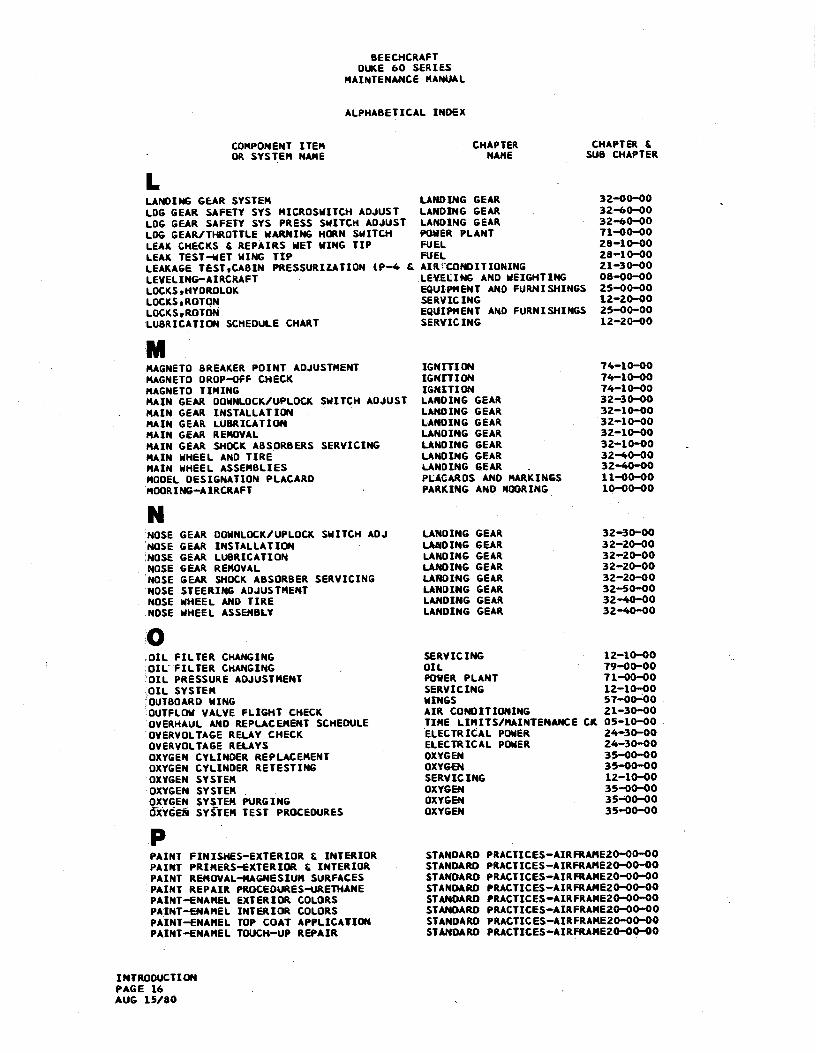
I.LANOING GEAR SYSTEM LANDING GEAR 32-00-00LDG GEAR SAFETY SYS MICROSWITCH ADJUST LANDING GEAR 32-60-00LOG GEAR SAFETY SYS PRESS SWITCH ADJUST LANDING GEAR 32-60-00LDG GEAR/THROTTLE WARNING HORN SWITCH POWER PLANT 71-00-00LEAK CHECKS & REPAIRS MET WING TIP FUEL 28-10-00LEAK TEST-MET WING TIP FUEL 28-10-00LEAKAGE TEST.CASIN PRESSURIIATION (P-4 & AIR CONDITIONING 21-30-00LEVELING-AIRCRAFT LEVELING AND WEIGHTING 08-00-00LOCKS,HYDROLOK EQUIPMENT AND FURNISHINGS 25-00-00LOCKS.ROTON SERVICING 12-20-00LOCKS,ROTON EQUIPMENT AND FURNISHINGS 25-00-00LUBRICATION SCHEDULE CHART SERVICING 12-20-00
MMAGNETO BREAKER POINT ADJUSTMENT IGNETION 74-10-00MAGNETO DROP-OFF CHECK IGNITION 74-10-00MAGNETO TIMING ISMITION 74-10-00MAIN GEAR DOWNLOCK/UPLOCKSWITCH ADJUST LANDING GEAR 32-30-00MAIN GEAR INSTALLATION LANOING GEAR 32-10-00MAIN GEAR LUBRICATION LANDING GEAR 32-10-00MAIN GEAR REMOVAL LANDING GEAR 32-10-00MAIN GEAR SHOCK ASSORBERS SERVICING LANDING GEAR 32-10-00MAIN WHEEL AND TIRE LANDING GEAR 32-40-00MAIN WHEEL ASSEMBLIES LANDING GEAR .
32-40-00MODEL DESIGNATION PLACARD PLACMtDS AND MARKINGS 11-00-00MOORING-AIRCRAFT PARKING AND MOORING 10-00-00
NNOSE GEAR DOWNLOCK/UPLOCK SWITCH ADJ LANDING GEAR 32-30-00emSE GEAR INSTALLATION LANDING GEAR 32-20-00NOSÆ GEAR LUBRICATION LANDING GEAR 32-20-00NOSE GEAR REMOVAL LANDING GEAR 32-20-00NOSE GEAR SHOCK ABSORBER SERVICING LANDING GEAR 32-20-00NOSE STEERING ADJUSTMENT LANDING GEAR 32-50-00NOSE WHEEL AND TIRE LANDING GEAR 32-40-00NDSE WHEEL ASSEMBLY LANOING GEAR 32-40-00
0OIL FILTER CHAMGING SERVICING 12-10-00OIL FILTER CHANGING OIL 79-00-00OIL PRESSURE ADJUSTMENT POWER PLANT 71-00-00OIL SYSTEM SERVICING 12-10-00OUTBOARD WING WINGS 57-00-00OUTFLOW VALVE FLIGHT CHECK AIR CONOITIONING 21-30-00OVERHAUL AND REPLACEMENT SCHEDULE TIME LIMITS/MAINTENANCE CK 05-10-00OVERVOLTAGERELAY CHECK ELECTRICAL POWER 24-30-00OVERVOLTAGERELAYS ELECTRICAL PONER 24-30-00OXYGEN CYLINOER REPLACEMENT OXYGEN 35-00-00OXYGEN CYLINDER RETESTING OXYGEN 35-00-00OXVGEN SYSTEM SERVICING 12-10-00OXYGEN SYSTEM OXYGEN 35-00-00OXYGEN SYSTEM PURGING OXYGEN 35-00-00ÖXYÖEÑSYSTEM TEST PROCEDURES OXYGEN 35-00-00
PPAINT FINISHES-EXTERIOR & INTERIOR STANDARD PRACTICES-AIRFRAME20-00-00PAINT PRIMERS-EXTERIOR & INTERIDR STANDARO PRACTICES-AIRFRAME20-00-00PAINT REMOVAL-MAGNESIUM SURFACES STANOARO PRACTICES-AIRFRAME20-00-00PAINT REPAIR PROCEDURES-URETNANE STANDARD PRACTICES-AIRFRAME20-00-00PAINT-ENANEL EXTERIDR COLORS STANDARD PRACTICES-AIRFRAME20-00-00PAINT-ENAMEL INTERIOR COLORS STANDARO PRACTICES-AIRFRAME20-00-00PAINT-ENANEL TOP COAT APPLICATION STANDARD PRACTICES-AIRFRAME20-00-00PAINT-ENAMEL TDUCH-UP REPAIR STANDARD PRACTICES-AIRFRAME20-00-00
INTRODUCTIONPAGE 16AUG 15/80

BEECHCRAFTDUKE 60 SERIES
MAINTENANCE MANUAL
ALPHABETICAL INDEX
COMPONENT ITEM CHAPTER CHAPTER &OR SYSTEM NAME NAME SUS CHAPTER
PPAINT-PREPARATION OF EXTERIOR FOR STANDARD PRACTICES-AIRFRAME20-00-00PAINT-SPECIAL PROCEDURES STANOARD PRACTICES-AIRFRAME20-OD-00PAINT-URETHANE EXTERIOR COLORS STANDARD PRACTICES-AIRFRAME20-DO-00PAINT-URETHANE PRETREATMENT PRIMER STANDARD PRACTICES-AIRFRAME20-OO-00PAINT-URETHANE STRIPPING & CLEANING STANDARD PRACTICES-AIRFRAME20-OO-00PAINT-URETNANE TOP COAT APPLICATION STANOARD PRACTICES-AIRFRAME20-OO-00PAINT-URETHANE TOUCH-UP REPAIRS STANDARD PRACTICES-AIRFRAME20-OO-00PAINTING KAGRESIUM SURFACES STANDARD PRACTICES-AIRFRAME20-OO-00PARKING BRAKE ADJUSTMENT LANDING GEAR 32-40-00PARKING BRAKE VALVE INSTALLATION LANDING GEAR 32-40-00PARKING BRAKE VALVE REMOVAL LANDING GEAR 32-40-00PARKING-AIRCRAFT PARKING AND MOORING 1Œ-00-00PITOT AND STATIC PRESSURE SYSTEM NAVIGATION 34-10-00PITOT AND STATIC SYSTER ICE AND RAIN PROTECTION 30-30-00PITOT SYSTEM LEAK TEST NAVIGATION 34-10-00PNEUMATIC PRESS REGULATION-TURN/SLIP PNEUMATIC 36-00-00PNEUMATIC PRESSURE SYSTEM PNEUMATIC 36-00-00PNEUMATIC PRESSURE SYSTEM ADJUSTWENT PNEUMATIC 36-00-00PNEUMATIC PRESSURE SYSTEM SERVICING PNEUMATIC 36-00-00PNEUMATIC SUPPLY PRESSURE REGULATORS PNEUMATIC 36-00-00PRESSURIZATION CHARACTERISTICS AIR GONDITIONING 21-30-00PRESSURIZATION CONTROL AIR CONDITIONING 21-30-00PRESSURIZATION LEAKAGE TESTeCABIN AIR CONDITIONING 21-30-00PRESSURIZATION SYSTEM AIR CONDITIONING 21-00-00PRESSURIZATION SYSTEM ADJUSTMENT AIR CONDITIONING 21-30-00PRESSURIZATION TEST PROCEDURE AIR CONDITIONING 21-30-00PRESSURIZATION TEST SWITCH AIR CONDITIONING 21-30-00PROP DEICER BRUSH BLOCK RESIST CHECK ICE AND RAIN PROTECTION 30-60-00PROP DEICER BRUSH REPLACEMENT ICE AND RAIN PROTECTION 30-60-00PROP DEICER BRUSH/SLIP RING RESIST ICE AND RAIN PROTECTION 30-60-00PROP DEICER SLIP RING MACWINING ICE AND RAIN PROTECTION 30-60-00PROPELLER ACCUMULATOR PROPELLERS 61-00-00PROPELLER ACCUMULATOR SERVICING 12-20-00PROPELLER ACCUMULATOR INSTALLATION PROPELLERS 61-00-00PROPELLER ACCUMULATOR REMOVAL PROPELLERS 61-00-00PROPELLER ADJUSTMENT PROPELLERS 61-00-00PROPELLER BLADE BEARING LUBRICATION SERVICING 61-00-00PROPELLER BLADE BEARING LUBRICATION PROPELLERS 61-00-00PROPELLER BLADE REPAIR PROPELLERS 6.1-00-00PROPELLER DEICER BOOT INSTALLATION ICE AND RAIN PROTECTION 30-60-00PROPELLER DEICER BOOT REMOVAL ICE ANO RAIN PROTECTION 30-60-00PROPELLER DEICER BOOT REPAIR ICE AND RAIN PROTECTION 30-60-00PROPELLER DEICER CONTINUITY TEST ICE AND RAIN PROTECTION 30-60-00PROPELLER DEICER HEAT TEST ICE AND RAIN PROTECTION 30-60-00PROPELLER DEICER TIMER CHECK ICE AND RAIN PROTECTION 30-60-00PROPELLER DEICING SYSTEM ICE AND RAIN PROTECTION 30-60-00PROPELLER FEATHERING ADJUSTMENT PROPELLERS 61-00-00PROPELLER GOVERNOR ADJUSTMENT PROPELLERS 61-00-00PROPELLER GOVERNOR INSTALLATION PROPELLERS 61-00-00PROPELLER GOVERNOR REMOVAL PROPELLERS 61-00-00PROPELLER INSTALLATION PROPELLERS 61-00-00PROPELLER LOW RPM AOJUSTMENT PROPELLERS 61-00-00PROPELLER REMOVAL PROPELLERS 61-00-00PROPELLER SERVICING POINTS SERVICING 12-20-00PROPELLER SYNCHRONIZER PROPELLERS 61-00-00PROPELLER SYNCHROSCOPE PROPELLERS 61-00-00PROPELLERS PROPELLERS 61-00-00PUBLICATION-VENDOR INTRODUCTION IN-TR-OOPUBLICATIONS-BEECH INTROOUCTION IM-TR-ODPUBLICATION5-SUPPLEMENTAAY INTRODUCTION IN-TR-OD
RREFRIGERATIVE AIR COOLING SYSTEM AIR CONDITIONING 21-50-00ROTON LOCKS SERVICING 12-20-00ROTON LOCKS EQUIPMENT/FURNISH5 25-00-00RUDDER BALANCIMG STABILIZERS 55-40-00
INTRODUCTIONPAGE 17
AUG 15/80
BEECHCRAFTDUKE 60 SERIES
MAINTENANCE MANUAL
ALPHABETICAL INDEX
COMPDNENT ITEM CHAPTER CHAPTER &OR SYSTEM NAME NAME SUB CNAPTER
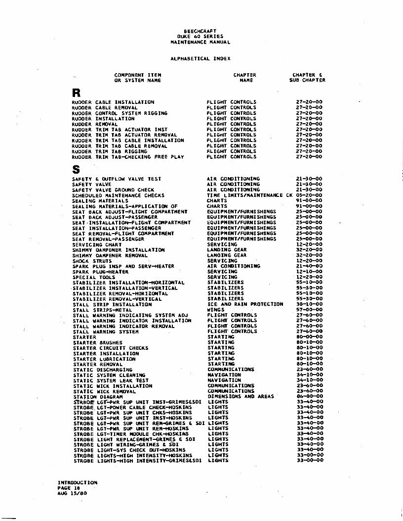
RRUDDER CABLE INSTALLATION FLIGHT CONTROLS 27-20-00RUDDER CABLE REMOVAL FLIGHT CONTROLS 27-20-00RUDDER CONTROL SYSTEM RIGGING FLIGHT CDNTROLS 27-20-00RUDDER INSTALLATION FLIGHT CONTROLS 27-20-00RUDDER REMOVAL FLIGHT CONTROLS 27-20-00RUDDER TRIM TAB ACTUATOR INST FLIGHT CONTROLS 27-20-00RUDDER TRIM TAB ACTUATOR REMOVAL FLIGHT CONTROLS 27-20-00RUDDER TRIA TAB CABLE IN5TALLATION FLIGHT CONTROLS 27-20-00RUDDER TRIM TAB CABLE REMOVAL FLIGHT CONTROLS 27-20-00RUDDER TRIM TAB RIGGING FLIGNT CONTROLS 27-20-00RUDDER TRIM TAB-CHECKING FREE PLAY FLIß¾T CONTROLS 27-20-00
SAFETY & DUTFLOW VALVE TEST AIR CONDITIONING 21-30-00SAFETY VALVE AIR CONDITIONING 21-30-00SAFETY VALVE GROUNO CHECK AIR CONDITIONING 21-30-00SCHEDULEO MAINTENANCE CHECKS TIME LIMITS/MAINTENANCE CK 05-20-00SEALING MATERIALS CHARTS 91-00-00SEALING MATERIALS-APPLICATION OF CHARTS 91-0Œ-00SEAT BACK AOJUST-FLIGHT COMPARTMENT EQUIPMENT/FURNISHINGS 25-00-00SEAT BACK A0JUST-PAS5ENGER EQUIPMENT/FURNISHINGS 25-00-0GSEATrINSTALLATION-FLIGHT COMPARTMENT EQUIPMENT/FURNISHINGS 25-00-00SEAT INSTALLATION-PASSENGER EQUIPMENT/FURNISHINGS 25-00-00SEAT REMOVAL-FLIGHT COMPARTMENT EQUIPMENT/FURNISHING5 25-00-00SEAT REMOVAL-PASSENGER EQUIPMENT/FURMISHINGS 25-0Œ-00SERVICING CHART SERVICING 12-20-00SHIMMY OAMPENER INSTALLATION LANDING GEAR 32-20-00SHIMMY DAMPENER REMOVAL LANOING GEAR 32-20-00SHOCK STRUTE SERVICING 12-20-00SPARK PLUG IN5P AND SERV-HEATER AIR CONDITIONIMG 21-40-00SPARK PLUS-HEATER SERVICING 12-10-00SPECIAL TOOLS SERVICING 12-20-00STABILIZER INSTALLATION-NORIZONTAL STASILIZERS 55-10-00STABILIZER INSTALLATION-VERTICAL STABILIZERS 55-30-00STABILIZER REMOVAL-NDRIZONTAL STABILIZERS 55-10-00STABILIZER REMOVAL-VERTICAL STABILIZERS 55-30-00STALL STRIP INSTALLATION ICE AND RAIN PROTECTION 30-10-00STALL STR1PS-METAL WINGS 57-00-00STALL WARNING INDICATING SYSTEM ADJ FLIGHT CONTROLS 27-60-00STALL MARNIMG INDICATOR INSTALLATION FLIGHT CONTROLS 27-60-00STALL WARNING INDICATOR REMOVAL FLIGHT CONTROLS 27-60-00STALL WARNING SYSTEM FLIGHT CONTROLS 27-60-00STARTER STARTING 80-00-00STARTER BRUSHES STARTIhn 80-10-00STARTER CIRCUITT CHECKS STARTING 80-10-00STARTER INSTALLATION STARTING 80-10-00STARTER LUBRICATION STARTING 80-10-00STARTER REMOVAL STARTING 80-10-00STATIC DISCHARGING COMMUNICATIONS 23-60-00STATIC SYSTEM CLEANING MAVIGATION 34-10-00STATIC SYSTEM LEAK TEST MAVIGATION 34-10-00STATIC MICK INSTALLATION COMMUNICATIONS 23-60-00STATIC MICK REMOVAL COMMUNICATIONS 23-60-00STATION DIAGRAM DIMENSIONS AND AREAS 06-00-00$7RSOEF LGY-PWR SUP UNIT INST-GRIMESESDI LIGHTS 33-40-00STROBE LGT-POWER CABLE CNECK-HOSKINS LIGWTS 33-40-00STROBE LGT-PWR SUP UNIT CHKS-HOSKINS LIGHTS 33-40-00STRO6E LGT-PWR SUP UNIT INST-MOSKINS LIGHTS 33-40-00STROBE LGT-PWR SUP UNIT REM-GRIMES & SOI LIGHTS 33-40-00STROBE LGT-PMR SUP UNIT REM-NDSKINS LIGH15 33-40-00STROBE LGT-TIMER MODULE CHK-HOSKINS LIGHTS 33-40-00STROBE LIGHT REPLACEMENT-GRIMES & SDI LIGHTS 33-40-00STROBE LIGHT MIRING-GRIMES & SOI LIGHTS 33-40-00STROBE LIGHT-SYS CHECK OUT-HOSKINS LIGHTS 33-40-00STROBE LIGHTS-HIGN INTENSITV-NOSKINS LIGHTS 33-00-00STROBE LIGHTS-HIGH INTENSITY-GRIMES&SDI LIGHTS 33-00-00
INTRODUCTIONPAGE 18AUG 15/80

BEECHCRAFTDUKE 60 SERIES
MAINTENANCE MANUAL
ALPHABETICAL INDEX
COMPONENT ITEM CHAPTER CHAPTER &DR SYSTEM NAME MAME SUB CHAPTER
STRUCTURAL REPAIR STRUCTURES 51-00-00SURFACE DEICER BOOT INSTALLATION ICE AND RAIN PROTECTION 30-10-00SURFACE DEICER BOOT REMOVAL ICE AND RAIN PROTECTION 30-10-00SURFACE DEICER COMPONENT LOCATION ICE AND RAIN PROTECTION 30-10-00SURFACE DEICER COMPONENT REPLACEMENT ICE AND RAIN PROTECTION 30-10-00SURFACE DEICER SERVICING ICE AND RAIN PROTECTION 30-10-00SYNCHRONIZER CMECKS PROPELLERS 61-00-00SYNCHRONIZER FLIGHT CHECKS . PROPELLERS 61-00-00SYMCHRONIZER FUNCTIONAL TEST PROPELLERS 61-00-00SYNCHRONIZER RIGGING PROPELLERS 61-00-00SYMCHRONIZER WIRING CHECK PROPELLERS 61-00-00
TTABLE OF TORQUES CHARTS 91-00-00TEST EQUIPMENT AIR CONDITIDMING 21-30-00TEST GUTFLON & SAFETY VALVE AIR CONDITIONING 21-30-00TEST PROCEDURE (P-4 & AFTER) AIR CONDITIONING 21-30-00TESTeCABIN PRESSURIZATIDN LEAKAGE AIR CONDITIONING 21-30-00THREAD LUBRICANTS CHARTS 91-00-00THREAD LU6RICANTS CHART SERVICING -
12-20-00TIRES LANDING GEAR 32-40-00TIRES SERVICING 12-20-00TIT INDICATOR CALIBRATION ENGINE INDICATING 77-00-00TOILET , CHEMICAL, CLEANING WATER/WASTE 38-30-00TOROUE WREMCHES STANDARD PRACTICES-AIRFRAME20-OO-00TOROUING COARSE THREAD BOLTS CHARTS 91-00-00TOROUING FINE THREAD BOLTS CHARTS 91-00-00TOWING-AIRCRAFT TOWING TAXING 09-00-00TRIM TAB FREE PLA¥ CHECK-AILERON FLIGNT COMTROLS 27-10-00TRIM TAB FREE PLAY CHECK-ELEVATOR FLIGHT CONTROLS 27-30-00TRIM TA6 FREE PLAY CHECK-RUODER FLIGHT CONTROLS 27-20-00TROUBLESHOOTING- ICE AND RAIN PROTECTION 30-40-00TROUBLESHOOTING- TURBINES 81-00-00TAOUBLESHOOTING-AIR CONDITIONING SYS AIR CONDITIONING 21-00-00TROUBLESHOOTING-AIRFOIL DEICER SYST ICE AND RAIN PROTECTION 30-10-00TROUBLESHOOTING-BATTERY ELECTRICAL POWER 24-31-10TROUBLESHOOTING-BATTERY SYSTEM ELECTRICAL PONER 24-31-00TROUBLESHOOTING-BRAKE SYSTEM LANDING GEAR 32-00-00TROUBLESHOOTING-ENGINE POWER PLANT 71-00-00TROUBLESHOOTING-GENERATOR SYSTEM ELECTRICAL POMER 24-30-00TROUBLESHOOTING-HEATER SYSTEM AIR CONDITIONING 21-00-00TAOUBLESHOOTING-LANDING LIGHTS LIGHTS 33-40-00TROUBLESHOOTING-LDG GEAR ELECT SYST LANDING GEAR 32-00-00TRDUBLESHOOTING-NEM-MATIC AUTOPILOT AUTO FLIGHT 22-11-00TROUBLESHOOTING-PITOT & STATIC SYST NAVIGATION 34-10-00TROUBLESHOOTING-PRESSURIZATION SYST AIR CONDITIONING 21-00-00TROUBLESHOOTING-PROP DEICING SYSTEM ICE AND RAIN PROTECTION 30-60-00TROUBLESHOOTING-PROP SYNCHRONIZER PROPELLERS 61-00-00TROUBLESHOOTING-STALL MARNING SYSTEM FLIGHT CONTROLS 27-60-00TROUBLESHOOTING-STARTER SYSTEM STARTING 80-10-00TROUBLESHOOTING-STROBE LIGHTS LIGMTS 33-40-00TURBOCRARGER CONTROL SYSTEM TURBINES 81-00-00TURBOCHARGER CRITICAL ALTITUOE TEST TURBINES 81-00-00TURBOCHARGER INSTALLATION & RUN-IN TURBINES 81-00-00TURBOCHARGER SYSTEM TURBINES 61-00-00TURBOCHAR6ER VARIABLE PRESS CONT ADJUST TURBINES 81-00-00TURBOCHARGER WASTEGATE SNAFT LUBE TURBINES 81-00-00TURBOCWARGER WASTEGATE VALVE ADJUST TURBINES 81-00-00TURBOCHARGER-TNRDTTLE/CONTROLLER RIG TURBINES 81-00-00
VVALVE CHECKeGRDUND.SAFETY AIR CONDITIONING 21-30-00VALVE FLIGHT CHECK,0UTFLOW AIR GONDITIONING Z1-30-00VALVE.SAFETY & OUTFLOW TEST AIR CONDITIONING 21-30-00
INTROOUCTIONPAGE 19
AUG 15/80

BEECHCRAFTDUKE 60 SERIES
MAINTENANCEMANUAL
ALPHABETICAL INDEX
COMPONENT ITEM CHAPTER CHAPTER &OR SYSTEM NAME MAME SUS CHAPTER
liu'WASTE DISPOSAL-OESC & OPER WATEK/WASTE 38-30-00WASTE DISPOSAL-MAINT PRACTICES WATER/WASTE 38-30-00WET WING TIP INSTALLATION FUEL 28-10-00WET WING TIP REMOVAL FUEL 28-10-00WIMOOW HINGE INSTALLATION-STORM WINDOWS 56-10-00WINDOW HINGE REMOVAL-STORM WINDOWS 56-10-00WIMDOW INSTALL-FLIGHT COMPARTMENT SIDE WINDOWS 56-10-00WINDOW INSTALLATION-CABIN 510E WINDOWS WINDOWS 56-20-00WINOOW LATCH INSTALLATIDN-STORM WINDOWS 56-10-00WINDOW LATCH REMOVAL-STORM WINDOWS 56-10-00WINDOW REMOVAL-CASIN SIDE WINDOWS 56-20-00WINDOW REMOVAL-FLIGNT COMPARTMENTSIDE WINDOWS 56-10-00WINDOWS-CLEANING SERVICING 12-20-00WINDOWS-CLEANING WINDOWS 56-00-00
INDSHIELD DEICER SYSTEM ICE AND RAIN PROTECTION 30-40-00WINDSHIELO FUNCTIONAL TEST-HEATED ICE AND RAIN PROTECTION 30-40-00WINDSHIELO NEAT SENSOR ELEMENT RES CHK ICE AND RAIN PROTECTION 30-40-00WINDSWIELO INSTALLATION WINDOWS 56-10-00WINDSHIELD REMOVAL WINDOWS 56-10-00WINDSHIELO RESISTANCE CHECK-HEATED ICE AND RAIN PROTECTION 30-40-00WING ACCESS OPENINGS WINGS 57-30-00WING ADJUSTMENT WINGS 57-00-00WING ASSEMBLY WINGS 57-00-00WING ATTACH FITTINGS WINGS 57-40-00WING BOLT REPLACEMENT P-4 THRU P-61 WERGS 57-00-00WING DISASSEM6LY WINGS 57-00-00WING INSTALLATION WENGS 57-00-00
ING REMOVAL WINGS 57-00-00WING TIP INSTALLATION WINGS 57-00-00WING TIP REMOVAL WINGS 57-00-00
"END"
INTRODUCTIONPAGE 20AUG 15/80

BEECHCRAFTDUKE 60 SERIES
MAINTENANCE MANUAL
CHAPTER 5
LIST OF PAGE EFFECTIVITY
CHAPTERSECTIONSUBJECT PAGE DATE
5-EFFECTIVITY 1 Nov 20/875-CONTENTS 1 Nov 20/875-10-00 201 Nov 20/87
202 Nov 20/87203 Nov 20/87204 Nov 20/87205 Nov 20/87206 Nov 20/87207 Nov 20/87
5-20-00 201 ¯
Nov 20/87202 Nov 20/87203 Nov 20/87204 Nov 20/87205 Nov 20/87206 Nov 20/87207 Nov 20/87208 Nov 20/87209 Nov 20/87210 Nov 20/87211 Nov 20/87212 Nov 20/87213 Nov 20/87214 Nov 20/87215 Nov 20/87216 Nov 20/87217 Nov 20/87218 Nov 20/87219 Nov 20/87220 Nov 20/87221 Nov 20/87222 Nov 20/87223 Nov 20/87224 Nov 20/87225 Nov 20/87226 Nov 20/87227 Nov 20/87228 Nov 20/87
"END"
5-EFFECTIVITYPage 1
A.18: Nov 20/87

BEECHCRAFTDUKE 60 SERIES
MAINTENANCE MANUAL
CHAPTER 5 - TIME LIMITS/MAINTENANCE CHECKS
TABLE OF CONTENTS
SUBJECT CHAPTER PAGE
5-10-00
Overhaul and Replacement Schedule . . . . . . . . . . . . . . . . . . . . . 201
Landing Gear . . . . . . . . . . . . . . . . . . . . . . . . . . . . . . . 201Power plant . . . . . . . . . . . . . . . . . . . . . . . . . . . . . . . 202Fuel system . . . . . . . . . . . . . . . . . . . . . . . . . . . . . . . 203Instruments . . . . . . . . . . . . . . . . . . . . . . . . . . . . . . . 204Electrical system . . . . . . . . . . . . . . . . . . . . . . . . . . . . 205Utility system . . . . . . . . . . . . . . . . . . . . . . . . . . . . . . 205Flaps and flight controls . . . . . . . . . . . . . . . . . . . . . . . . 206Miscellaneous . . . . . . . . . . . . . . . . . . . . . . . . . . . . . . 207
5-20-00
Scheduled Maintenance Checks - Maintenance Practices . . . . . . . . . . . . . 201
100-HOURINSPECTION............................202
Operational Inspection . . . . . . . . . . . . . . . . . . . . . . . . . . . 202Power Plant . . . . . . . . . . . . . . . . . . . . . . . . . . . . . . . 206Nacelles . . . . . . . . . . . . . . . . . . . . . . . . . . . . . . . . . . 210Wings And Carry-Through Structure . . . . . . . . . . . . . . . . . . . . . 211Cabin and Baggage Compartment . . . . . . . . . . . . . . . . . . . . . . .
214Nose Section . . . . . . . . . . . . . . . . . . . . . . . . . . . . . . . . 217Rear Fuselage and Empennage . . . . . . . . . . . . . . . . . . . . . . . . 218Main Gear And Brakes . . . . . . . . . . . . . . . . . . . . . . . . . . . . 220Nose Gear . . . . . . . . . . . . . . . . . . . . . . . . . . . . . . . . . 220Landing Gear Operation . . . . . . . . . . . . . . . . . . . . . . . . . . . 222General . . . . . . . .. . . . . . . . . . . . . . . . . . . . . . . . . . . 224
Propeller Deicer System Inspection . . . . . . . . . . . . . . . . . . . . . . 227
Electric Propeller Deicer (50-Hour Guide) . . . . . . . . . . . . . . . . . 227Electric Propeller Deicer (100-Hour Guide) . . . . . . . . . . . . . . . . . 227
"END"
5-CONTENTSPage 1
A18 Nov 20/87

BEECHCRAFTDUKE 60 SERIES
MAINTENANCE MANUAL
OVERHAUL AND REPLACEMENT SCHED- as well as the igniter power relayULE and Landing Gear Control relay.
The first overhaul or replacement must be Airplanes operated for Air Taxi, or otherperformed not later than the recommended than normal operation, and airplanesperiod. The condition of the item at the operated in humid tropics, or cold andend of the first period can be used as a damp climates, etc., may need more fre-criterion for determining subsequent quent inspections for wear, corrosionperiods applicable to the individual air- and/or lack of lubrication. In theseplane or fleet operation, provided the areas, periodic inspections should beoperator has an approved monitoring sys- performed until the operator can set histem. own inspection periods based on experi-
ence.The time periods for inspections noted inthis manual are based on average usage andaverage environmen .al conditions.
NOTENOTE
The date noted on the "STANDARDThe recommended periods do not AIRWORTHINESSCERTIFICATE", EAAconstitute a guarantee the item Form No. 8100-2, which is issuedwill reach the period without with each new airpTane-, is to bemalfunction as the aforementioned used as the basis for all TBO orfactors cannot be controlled by replacement components listed inthe manufacturer. the following schedule.
SPECIAL CONDITIONS CAUTIONARY NOTENOTICE
An engine cycle is defined as theperiod of time from the initial
WARNINH3 start to shutdown of the engine.This encompasses start-up,
Prior to performing maintenance increase to full or partial poweron an engine or the Airframe, (as required during a flightALWAYSpull the starter control regime) and back to completecircuit breakers and the Landing engine shutdown. Normal opera-Gear circuit breaker. This will tion results in the number ofkilT power to the starter control landings being equivalent to
engine cycles.
OVERHAUL AND REPLACEMENT SCHEDULE
ITEM OVERHAUL OR REPLACE
NOTE
"On Condition" items are to be overhauled or replaced wheninspection or performance of these items reveal potentiallyunsafe or unserviceable condition.
LANDING GEAR
Main gear Every 2000 hours
5-10-00Page 201
A18 Nov 20/87

BEECHCRAFTDUKE 60 SERIES
MAINTENANCE MANUAL
OVERHAUL AND REPLACEMENT SCHEDULE (Cont'd)
ITEM OVERHAUL OR REPLACE
LANDING GEAR (Cont'd)
Nose Gear Every 2000 hours
Actuator assembly Every 4000 hours or on condi-tion
Retract motor Every 2000 hours
Retract motor brushes Every 500 hours or on condition
Shimmy damper Every 2000 hours or 3 years
heels and tires On condition
Brake assembly On condition
Brake lining On condition
Master cylinder On condition
Shuttle valve assembly On condition
Parking brake valve On condition
All hose On condition
POWER PLANT
Engine Every 1600 hours for newengines with serial numbersL-804-59 and up and remana-factured engines shippedafter March 1, 1976 andremanufactured and over-hauled engines which incor-porate improved cylinderassemblies (as described isthe latest edition of AverLycoming Service BulletioNo. 334); every 1200 hoursfor all other engines
Engine controls On condition
Engine vibration isolator mounts On condition
Exhaust system On Condition
5-10-00Page 202Nov 20/87 A3

BEECHCRAFTDUKE 60 SERIES
MAINTENANCE MANUAL
OVERHAUL AND REPLACEMENT SCHEDULE (Cont'd)
ITEM OVERHAUL OR REPLACE
POWER PLANT (Cont'd)
Turbocharger and waste gate On condition
Oil cooler On condition (replace whencontaminated)
Propeller (Hartze11) Every 2000 hours or 5 calendaryears, whichever occursfirst
Propeller controls On condition
Propeller governor every 1600 hours
Dry air pressure pump Every 600 hours or on condition
Propeller Accumulator Etery 1600 hours
Hoses carrying flammable liquids When condition warrants, 5years from date of deliv-ery, or at engine overhaul,whichever occurs first
All other hoses On condition
FUEL SYSTEM
Fuel cells On condition
Nacelle fuel quantity transmitter On condition.
Wing fuel quantity transmitter On condition.
Fuel cell drain valve On condition
Fuel system check valves On condition
Fuel selector-valve Every 1000 hours
Fuel boost pump Every 800 hours
Float valve On condition
Hoses carrying flammable liquids When condition warrants, 5years from date of deliv-ery, or at engine overhaul,whichever occurs first
All other hoses On condition
5-10-00Page 203
A18 Nov 20/87

BEECHCRAFTDUKE 60 SERIES
MAINTENANCE MANUAL
OVERHAUL AND REPLACEMENT SCHEDULE (Cont'd)
ITEM OVERHAUL OR REPLACE
FUEL SYSTEM (Cont'd)
Fuel pump, engine driven Every 1200 hours
INSTRUMENTS
Turn and bank indicator On condition
Altimeter Every 24 months per FAAdirec-tive
Directional gyro On condition
Gyro horizon On condtion
Dry air pressure gage On condition
Cabin altitude control On condition
Cabin altitude controller filter - standard On condition
Cabin altitude controller filter - motorized Every 100 hours
Manifold pressure gage On condition
Airspeed indicator On condition
Cabin differential pressure gage On condition
Cabin altitude and pressure differential indicator On conditionRate-of-climb indicator On condition.
Fuel pressure gage On condition
Fuel flow gage On condition
Tachometer On condition
Flap position Ëndicator On condition
Free air temperature indicator On condition
Gyro instrument filter Every 500 hours
Air pump inlet filter On condition
All hoses On condition
5-10-00Page 204Nov 20/87 A1

BEECHCRAFTDUKE 60 SERIES
MAINTENANCE MANUAL
OVERHAUL AND REPLACEMENT SCHEDULE (Cont'd)
ITEM OVERHAUL OR REPLACE
INSTRUMENTS (Cont'd)
Air pump inline filter 300 hours
ELECTRICAL SYSTEM
Landing gear dynamic brake relay On condition
Battery master relay On condition
Para11eling relay On condition
All other relays On condition
Voltage regulators On condition
Heater vibrators Replace at heater overhaul
Starter Inspect at engine overhaul andoverhaul or replace on con-dition
Starter relay On condition
Generator On condition
Battery (Emergency Locator Transmitter) At 50% of useful life (asstated on the battery) orany time transmitter isused more than one cumula-tive hour or after inad-vertent activation ofunknown duration
UTILITY SYSTEM
Cabin _beater . Every 1000 hours or whenever- pressure decay test
requirements cannot be met.See appropriate manufactur-er's manual
Heater igniter and plug On condition
Heater fuel pump On condition
Heater fuel spray nozzle Replace at heater overhaul,
5-10-00Page 205
A18 Nov 20/87

BEECHCRAFTDUKE 60 SERIES
MAINTENANCE MANUAL
OVERHAUL AND REPLACEMENT SCHEDULE (Cont'd)
ITEM OVERHAUL OR REPLACE
UTILITY SYSTEM (Cont'd)
Heater fuel shut-off valve On condition
Combustion blower On condition
Combustion blower brushes Every 500 hours
Vent blower On condition
Vent blower brushes Every 500 hours
Condenser blower On condition
Condenser blower brushes On condition
Oxygen regulator Every 2000 hours or 48 months
Oxygen cylinder (3HT) Hydrostatica11y test every 3years, replace every 24years or 4,380 refills (ICCregulation)
Oxygen cylinder (3A or 3AA) Hydrostatica11y test every 5years: no replacement dura-tion
Differential control valve (P-4 thru P-307) Inspect every 100 hours,replace on condition
Outflow valve (308 and after) Perform functional test every500 hours
Safety valve (P-4 thru P-307) Inspect every 100 hours,replace on condition
Safety valve (P-308 and after) Perform functional test every500 hours
FLAPS AND FLIGHT CONTROLS
Flight controls On condition
Aileron tab actuator On condition
Elevator tab actuator On condition
Rudder tab actuator On condition
Rudder pedal arm On condition or at 2000 hours
5-10-00Page 206Nov 20/87 Alf

BEECHCRAFTDUKE 60 SERIES
MAINTENANCE MANUAL
OVERHAUL AND REPLACEMENT SCHEDULE (Cont'd)
ITEM OVERHAUL OR REPLACE
FLAPS AND FLIGHT CONTROLS (Cont'd)
Flap motor and drives Every 2000 hours
F1ap gearbox Every 2000 hours
Flap actuators Every 2000 hours
Flap flexible shaft Every 2000 hours
MISCELLANEOUS
Wing bolts Replace 10 years after theinitial inspection. or oncondition. See Chapter57-00-00
"END"
5-10-00Page 207
A18 Nov 20/87
BEECHCRAFTDUKE 60 SERIES
MAINTENANCE MANUAL
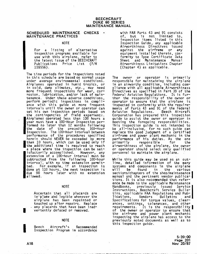
SCHEDULED MAINTENANCE CHECKS - with FAR Parts 43 and 91 consistsMAINTENANCE PRACTICES of, but is not limited to,
Iinspection items listed in this
NOTE Inspection Guide, any applicableAirworthiness Directives issued
For a listing of alternative against the airframe or anyinspection programs available for equipment installed therein, con-use with this airplane, refer to formity to Type Certificate Datathe latest issue of the BEECHCRAFT Sheet and Maintenance ManualPublications Price List (P/N Airworthiness Limitations Chapter118556). (Chapter 4) as applicable.
The time periods for the inspections notedin this schedule are based on normal usage The owner or operator is primarilyunder average environmental conditions. responsible for maintaining the airplaneAirplanes operated in humid tropics, or in an airworthy condition, including com-in cold, damp climates, etc., may need pliance with all applicable Airworthinessmore frequent inspections for wear, cor- Directives as specified in Part 39 of therosion, lubrication, and/or lack of main- Federal Aviation Regulations. It is fur-tenance. Under these adverse conditions, ther the responsibility of the owner orperform periodic inspections in compli- operator to ensure that the airplane isance with this guide at more frequent inspected in conformity with the require-intervals until the owner or operator can ments of Parts 43 and 91 of the Federalset his own inspection periods based on Aviation Regulations. Beech Aircraftthe contingencies of field experience. Corporation has prepared this inspectionAirplanes operated less than 100 hours a guide to assist the owner or operator inyear must have a 100-Hour Inspection per- meeting the foregoing responsibilities.formed no later than 12 months following This inspection guide is not intended tothe date of the preceding 100-Hour be a11-inclusive, for no such guide canInspection. The 100-hour interval between replace the good judgment of a certifiedperformance of the procedures specified airframe and power plant mechanic in theherein should NEVERbe exceeded by more performance of his duties. As the oneIthan10 hours, which can he used only if primarily responsible for thethe additional time is required to reach airworthiness of the airplane, the ownera place where the inspection can be sat- or operator should select only qualifiedlisfactorilyaccomplished. However, any personnel to maintain the airplane.extension of a 100-hour interval must besubtracted from the following 100-hour While this guide may be used as an out-interval, with no time extension permit- line, detailed information of the manyted. For example, if an inspection is systems and components in the airplanedone at 110 hours, the next inspection is will be found in the variousdue 90 hours later with no extension sections/chapters of the shop/maintenanceallowed. manual and the pertinent vendor publica-
tions. It is also recommended that refer-ence be made to the applicable Maintenance
NOTE Handbooks, previously issued ServiceInstructions, Beechcraft Service Bulle-
Ascertain that all placards are tins, applicable FAA Regulations and Pub-in-plate and legible whenever the lications, Vendors Bulletins andairplane has been repainted or Specifications for torque values, clear-touched up after repairs. Replace ances, settings, tolerances, and other
- any placards that have been inad- requirements. It is the responsibilityvertently defaced or removed. of the owner or operator to ensure that
the airframe and power plant mechanicinspecting the airplane has access to the
NOTE previously noted documents as well as to
I Beech Aircraft's Recommendedthis inspection guide.
Inspection Program in accordance5-20-00
Page 201A18 Nov 20/87

BEECHCRAFTDUKE 60 SERIES
MAINTENANCE MANUAL
Beech Aircraft Corporation issues service Service Bulletin to his particular set oinformation for the benefit of owners and operating conditions.operators in the form of two classes ofService Bulletins. MANDATORY(Red Border) In the final analysis it is the responsiService Bulletins are changes, bility of the owner or operator to ensurinspections or modifications that could that all previously issued Class I and Iaffect safety. The factory considers Service Instructions and Beechcraft Sercompliance with these Service Bulletins vice Bulletins which are pertinent to himandatory. OPTIONAL(No Border) Service -particular operation are complied with.Bulletins cover changes, modifications,improvements or inspections which may NOTEbenefit the owner. Due to the wide rangeof information covered by the OPTIONAL In addition to the inspectionsService Bulletin, each owner or operator prescribed by this schedule, theis responsible for conducting a thorough altimeter instrument and staticreview of each Optional Service Bulletin system and all ATC transpondersto determine if compliance is required MUSTbe tested and inspected atbased on the applicability of the OPTIONAL 24-month intervals in compliance
with the requirements specifiedin FARPart 91.
100-HOUR INSEECTION
A. OPERATIONALINSPECTION MECH INSP
L R
1. STARTERS - Check for proper operatton, unusual noisesand dragging. Check starter energized light (ifinstalled) and/or loadmeter to ensure starter disengage-ment when the starter switch is released.
2. CYLINDER HEADTEMPERATURE- Check for;proper operation,temperature and fluctuations.
3. ALTERNATOR- Check the output.
4. PROPELLEROPERATION- Cycle propeller and check forproper rpm drop and smoothness of operation.
5. PROPELLERSYNCHRONIZER- Check for proper operation.
6. PROPELLER DEICER - Check for proper operation andamperage drawn on ammeter.
5-20-00Page 202Nov 20/87 A1
BEECHCRAFTDUKE 60 SERIES
MAINTENANCE MANUAL
A. OPERATIONALINSPECTION(Cont'd) MECH INSP
L R
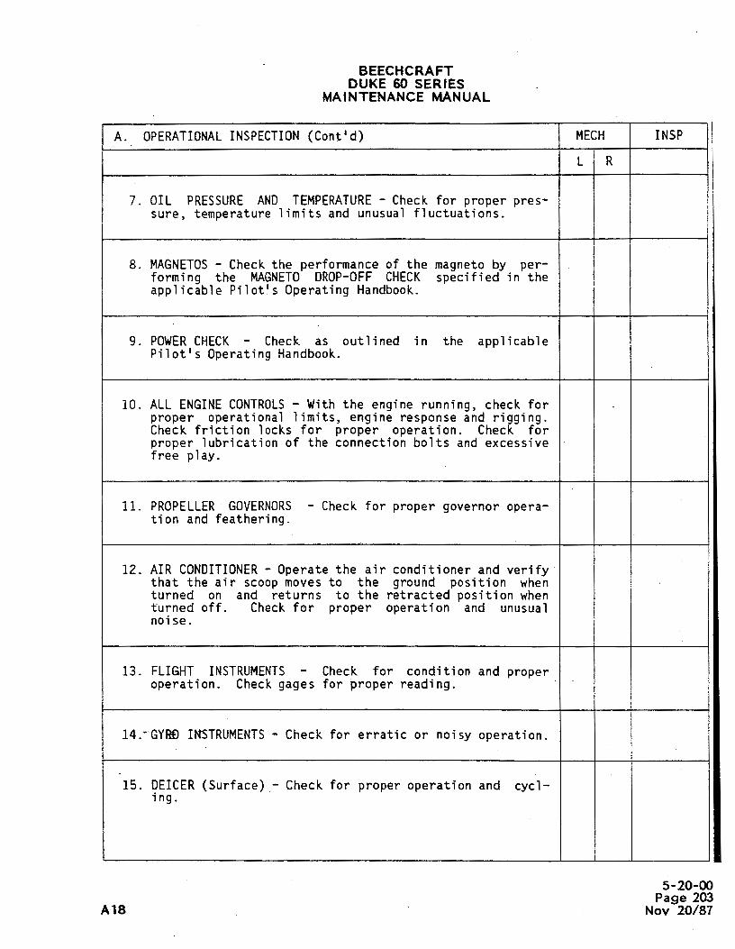
7. OIL PRESSURE AND TEMPERATURE- Check for proper pres-sure, temperature limits and unusual fluctuations.
8. MAGNETOS- Check the performance of the magneto by per-forming the MAGNETODROP-OFF CHECK specified in theapplicable Pilot's Operating Handbook.
9. POWERCHECK - Check as outlined in the applicablePilot's Operating Handbook.
10. ALL ENGINECONTROLS- With the engine running, check forproper operational limits, engine response and rigging.Check friction locks for proper operation. Check forproper lubrication of the connection bolts and excessivefree play.
11. PROPELLER GOVERNORS- Check for proper governor opera-tion and feathering.
12. AIR CONDITIONER- Operate the air conditioner and verifythat the air scoop moves to the ground position whenturned on and returns to the retracted position whenturned off. Check for proper operation and unusualnoise.
13. FLIGHT INSTRUMENTS- Check for condition and properoperation. Check gages for proper reading.
14. GYRÐINSTRUMENTS- Check for erratic or noisy operation.
15. DEICER (Surface) - Check for proper operation and cycl-ing.
|5-20-00
Page 203A18 Nov 20/87

BEECHCRAFTDUKE 60 SERIES
MAINTENANCE MANUAL
A. OPERATIONALINSPECTION (Cont'd) MECH INSP
L R
..16. IDLE RPM AND MIXTURESETTINGS - Check for both proper
rpm and mixture settings. Check controls for freedom ofoperation.
17. IGNITION SWITCH- Rotate the ignition switch through theOFF position to the extreme limit of switch travel; ifthe engine stops firing, the switch is normal. If theengine continues to run with the switch held in the pastOFF position, it is an indication that one magneto isstill "hot" or ungrounded. When the switch is releasedfrom the past OFF position, it should automaticallyreturn to normal OFF and the engine should stop running.However, any ignition switch exhibiting this abnormalcondition should be replaced.
18. HEATINGANDVENTILATINGSYSTEM- Cneck for proper opera-tion, heat and airflow output. Check controls for free-dom of operation.
19. PRESSURIZATIONSYSTEM- Check for proper 'operation.
20. FUEL QUANTITYANDFUEL FLOWGAGES - Check for properoperation and unusual fluctuations.
21. FUEL BOOSTPUMPS - Check for proper operation.
22. FUEL TANKSELECTOR- Check for proper operation and feelfor positive detent and proper placarding.
23. ALL LIaWTS - Check for condition, attachment, cracked orbroken lenses. Check switches, knobs and circuit break-ers for looseness and operation.
24. STALL WARNINGSYSTEM- Check for proper operation.
5-20-00Page 204Nov 20/87 A

BEECHCRAFTDUKE 60 SERIES
MAINTENANCE MANUAL
A. OPERATIONALINSPECTION(Cont'd) MECH INSP
L R
25. RADIO OPERATION - Check for proper operation, securityof switches and knobs.
26. FLAPS - Check for noisy operation, full travel and prop-er indication.
27. PITOT HEAT- Check for proper heating of the unit.
28. BRAKES- Check for condition and wear, ease of operationand proper release of the parking brake. Check for unu-sual brake chatter.
29. EMERGENCYLOCATORTRANSMITTER- Check for proper opera-tion. Tune radio to 121.5 MHz on VHF or 243 MHz on UHF,then turn ELT switch to ON and monitor for one signal.Turn ELT switch OFF, then place in ARMposition.
30. OXYGENSYSTEM- Functionally check the oxygen system forproper operation. Check the oxygen bottle shutoff valvefor proper operation.
31. SWITCHES, CIRCUIT BREAKERS- Check for proper operation.
32. FLIGHT CONTROLS, TRIM CONTROLSAND TRIM INDICATOR-
Check freedom of movement and proper operation throughfull travel with and without flaps extended. Checkelectric trim controls for operation.
33. IDLE CUT-OFF - Check for proper operation and freedom ofmovement.
5-20-00Page 205
A18. Nov 20/87

BEECHCRAFTDUKE 60 SERIES
MAINTENANCE MANUAL
B. POWERPLANT MECH INSP
L R
NOTE
After the first 25 hours of engine operatingtime, a new, remanufactured, or newly over-hauled engine should be given a 100-hourinspection including draining and renewing ofoil.
1. COWLING - Check for condition and security. Remove theupper and lower cowling and clean. Inspect for cracks.
2. COWLFLAPS - Check for travel, deformation and security.Inspect for cracks.
3. SPARKPLUGS - Clean, inspect, regap, test and replace asnecessary. Tighten spark plugs to proper torque andcheck ignition harness condition and for proper attach-ment.
4. COMPRESSION- Perform differential compression test.
5. PLUMBING- Inspect plumbing and associated accessoriesfor condition (such as cracks) and attachment. Checkplumbing clearance and secure against possible chafing.
6. ENGINEOIL SUMP- Check for cracks, leaks, deformationand security.
7. OIL DIPSTICK - Check the dipstick for rust and generalconditico. Inspect the dipstick tabs for security andthat the-tabs are not bent.
8. OIL SUMP DRAINSANDFILTERS - Check for metal particleson filters. Check for proper torque after installation.Check drain plugs for leaks.
5-20-00Page 206Nov 20/87 A18

BEECHCRAFTDUKE 60 SERIES
MAINTENANCE MANUAL
B. POWERPLANT (Cont'd) MECH INSP
L RNOTE
Change oil and oil filter per LycomingT10-541 Series Operating Manual.
9. OIL COOLER- Check oil cooler, lines and fittings forcondition, security, chafing and leaks.
10. PROPELLER AND MOUNTINGBOLTS - Check for condition andsecurity. Check the tip of the blades for evidence oflightning strikes. If there is evidence of lightningstrikes, consult the propeller manufacturer, the enginemanufacturer and Beech Aircraft Corporation. Inspect theblades for cracks, dents, nicks, scratches, erosion,corrosion, security and movement in the hub.
11. PROPELLERSPINNER - Check for deformation, security andcracks.
12. PROPELLER HUB - Check for cracks, excessively leakingseals and condition.- Check propeller dome pressure.
13. PROPELLERACCUMULATOR- Check for proper operation.
14. STARTER- Check for condition, attachment and chafed orloose wires.
15. MAGNETOS- Check contact points for proper clearance.Points with deep pits or excessively burned areas mustbe discarded. Inspect the cam follower felt pad forprd)er lubrication and clean the compartment with aclean, dry cloth. Check timing.
16. IGNITION HARNESS- Inspect for fraying and attachment.
5-20-00Page 207
A16l Nov 20/87

BEECHCRAFTDUKE 60 SERIES
MAINTENANCE MANUAL
B. POWERPLANT(Cont'd) MECH INSP
L R
17. CYLINDERSANDBAFFLES - Check cylinders and exhaust man-ifold for obvious leaks, security and cracks; checkbaffles for cracks and security. Check cylinders forbroken cooling fins and loose or missing base nuts.
NOTE
Accomplish valve inspection every 400 hoursof operation per Lycoming T10-541 SeriesOperating Manual.
18. EXHAUST SYSTEM - Check for deformation, security,cracks, leaks, loose or missing nuts and clamps. Checkfor thin wall condition which may occur due to normalinternal erosion on stacks which have long service time.
19. FIREWALL- Check for wrinkles, damage or cracks. Checkall electrical and control access holes for proper seal-ing.
20. HOSE AND DUCTS - Check all fuel, oil and air hose orduct for leakage, cracks, deterioration and damage.Check fittings for security.
21. ENGINE ACCESSORIES - Check for condition, security andleaks. Check wiring, hoses and tubes for chafing, secu-rity and leaks.
22. GENERATOR- Check for condition, attachment and chafedor loose wires.
23. ENGINE 1MOUNTS- Check for cracks, corrosion and securi-ty. Inspect rubber cushions, mount bolts and nuts, andgrounding straps for condition and security.
24. PROPELLERGOVERNOR- Check for leaks and control arm forsecurity.
5-20-00Page 208Ncar 20/87 Alf

BEECHCRAFTDUKE 60 SERIE:S
MAINTENANCE MANUAL
B. POWERPLANT(Cont'd) MECH INSP
L R
25. ENGINE CONTROLS - Check controls and associated equip-ment for condition, attachment, alignment and rigging.Each 300 hours remove the throttle cable connectionbolts and check for wear.
26. ELECTRICALWIRINGAND EQUIPMENT - Inspect electricalwiring and associated equipment and accessories forfraying and attachment.
27. AIR CONDITIONERCOMPRESSOR- Check for security andattachment. Check refrigerant and oil levels. Check beltfor tension and worn or frayed condition,
28. INDUCTION AIR FILTER - Check for condition, cleanlinessand security.
29. INDUCTION SYSTEMANDALTERNATEAIR - Check flexible airducts for delamination of the inner lining. Check thealternate air valve for blockage, security, cracks,operation and wear.
30. FUEL INJECTION CONTROLVALVE - Clean the screen andcheck for damage. Install screen and check for leaks.
31. FUEL INJECTION SYSTEM- Inspect all fuel injection com-ponents, lines and fittings for evidence of fuel leaks,fraying and cracking.
32 TUËBOCHARGERS- Check the compressor wheel for nicks andcracks. Check linkages for security and proper opera-tion.
33. TURBINE INLET TEMPERATUREINDICATOR- Check the indica-tor for accuracy and calibrate as outlined under theheading TIT INDICATORCALIBRATION in Chapter 77-00-00.
5-20-00Page 209
A18 Nov 20/87

BEECHCRAFTDUKE 60 SERIES
MAINTENANCE MANUAL
B. POWERPLANT(Cont'd) MECH INSP
L R
34. ELECTRIC PROPELLERDEICER - Check for service damage tothe deicer heaters, brush rods, springs and brushes.Check the lead strap and all other clamps, connectorsand wiring for electrical soundness. Check the sliprings for roughness, cracks, burned or discolored areasand for deposits of oil, grease or dirt. Check forsecurity and attachment of all components. Check deicerboots for wrinkles, loose or torn areas.
C. NACELLES MECH INSP
L R
1. NACELLE SKIN - Check for deformation and obvious damageor cracks. Check for loose or missing rivets.
2. NACELLESTRUCTURE- Check for cracks and deformation.Check for loose or missing rivets and concealed damage.
3. PNEUMATIC PRESSURE REGULATORS- Check for condition,security and attachment.
4. INLINE FILTERS - Clean or replace, as required, the fil-ter in each nacelle as outlined under the heading SER-VICING in Chapter 36-00-00.
5. BATTERY - Inspect for clean, tight connections and cor-rect fluid level. Add distilled water as required.Inspect the vent hose at the battery box forobstructions. The battery box should be washed out thor-oughly and dried each time the battery is removed andcleaned.
6. FUEL QUANTITY TRANSMITTER - Check for attachment andelectrical connection.
5-20-00Page 210Nov 20/87 A1

BEECHCRAFTDUKE 60 SERIES
MAINTENANCE MANUAL
C.. NACELLES(Cont'd) MECH INSP
L R
7. FUEL CELLS AND VENTS - Inspect fuel cells for leakageand vent lines for security as outlined in Chapter28-10-00.
8. PLUMBING - Check for leakage, chafing, condition andsecurity.
9. ELECTRICALWIRINGAND EQUIPMENT- Inspect for chafing,damage, security and attachment.
10. AIR CONDITIONING - Check for condition, security andattachment.
D. WINGSANDCARRY-THROUGHSTRUCTURE MECH INSP
L R
1. SKIN - Check for deformation and obvious damage. Checkfor cracks, loose -or missing rivets. If damage isfound, check adjacent structure. Check for indicationsof hard landing or excessive flight loading.
2. STRUCTURE - Check for cracks, deformation and concealeddamage. Check for loose or missing rivets.
3. ACCESS DOORSAND PANELS - Inspect for cracks, proper fitand attachment.
4. CAÚLES, PULLEYSANDTURNBUCKLES- Check the wing flightcontrol components, cables and pulleys. Replace controlsystem components (push rods, turnbuckles, end fittings,castings, etc.) that have bulges, splits, bends, orcracks. Check.control cables, pulleys, and associatedequipment for condition, attachment, alignment, clear-ance, and proper operation. Replace cables that havebroken strands or evidence of corrosion. Check cablesfor proper tension at the first inspection and every100-hours thereafter.
5-20-00Page 211
A18 Nov 20/87

BEECHCRAFTDUKE 60 SERIES
MAINTENANCE MANUAL
D. WINGSANDCARRY-THROUGHSTRUCTURE(Cont'd) MECH INSP
L R
5. AILERONS- Check for condition and security. Check forcracks, loose or missing rivets and freedom of movement.Check hinge bearings and brackets for condition, push-pull rods for security and rod ends for corrosion.
6. AILERONTRIM.TAB - Check for attachment and freedom ofmovement. Check free play as outlined under the headingCHECKINGAILERONTAB FREE PLAY IN Chapter 27-00-00.
7. FUEL CELLS AND VENTS - Inspect fuel cells for leakageand vent lines for security as out1Ìned in Chapter28-10-00.
8. PLUMBING - Check for leakage, chafing, condition andsecurity.
9. ELECTRICALWIRINGANDEQUIPMENT- Inspect for chafing,damage, security and attachment.
10. FLAP LIMIT SWITCHES- Check for condition, security andfreedom of operation.
11. FLAPS ANDACTUATORS- Check for condition, security,binding or chafing of actuator cables. Check flap skinand structure for cracks, loose or missing rivets. Checkroller bearings and tracks for condition. Check stoparea for condition and damage.
12. FLAP POSITION TRANSMITTER- Check for security and oper-ation.
13. DRAIN HOLES - Check the drain holes in the left andright upper wing attach fittings to assure that they areopen and free of obstruction.
5-20-00Page 212Nov 20/87 A1

BEECHCRAFTDUKE 60 SERIES
MAINTENANCE MANUAL
D. WINGSANO CARRY-THROUGHSTRUCTURE(Cont'd) MECH INSP
L R
14, WING SPAR CAP - Inspect the wing spar cap for corrosionas outlined in Chapter 57-00-00.
15. WINGBOLTS - Check wing bolts for proper torque at thefirst 100-hour inspection and at the first 100-hourinspection after each reinstallation of the wing attachbolts. Refer to Chapter 57-00-00 for wing bolt, nut andfitting inspection criterion and frequency.
16. STALL WARNINGVANE - Check for condition andobstructions.
17. FUEL QUANTITY TRANSMITTER- Check for attachment andelectrical connection.
18. NAVIGATIONLIGHTS - Check for cracked or broken lensesand replace bulbs as necessary.
19. LANDING LIGHTS - Check for security and operation.Replace lens and bulbs as necessary.
20. FUELBOOSTPUMPSANDFUEL LINES - Check for condition,i security and leaks. Check lines for signs of chafing or
cracks.
21. FUEL SELECTORVALVE- Check for security, operation andleakage.
22. FUELSTRAINERS - Inspect ati clean as outlined under theheading ENGINE FUEL FILTERS AND SCREENS in Chapter12-10-00 of this Maintenance Manual.
5-20-00Page 213
A18 Nov 20/87

BEECHCRAFTDUKE 60 SERIES
MAINTENANCE MANUAL
E. CABINANDBAGGAGECOMPARTMENT MECH - INSP
1. SKIN - Inspect skins for deformation, cracks and looseor missing rivets. If damage is found, check adjacentstructure.
2. STRUCTURE- Check for cracks and deformation. Check forloose or missing rivets and concealed damage.
3. CABLES, PULLEYSANDPRESSURESEALS - Check the flightcontrol components, cables and pulleys. Replace controlsystem components (push rods, turnbuckles, end fittings,castings, etc.) that have bulges, splits, bends, orcracks. Check control cables, pulleys, and associatedequipment for condition, attachment, alignment, clear-ance and proper operation. Replace cables that have bro-ken strands or evidence of corrosion. Check cables forproper tension at the first inspection and every100-hours thereafter.
4. PRESSURIZATION CONTROLVALVES- On airplane serials P-4thru P-307, check the cabin pressurization safety valveand outflow valve differential adjustment every 300hours of airplane operation or annually. On airplaneserials P-308 and after,perform a functional test of theoutflow and safety valves every 500 hours. On airplaneserials P-308 and after, clean the cabin pressurizationcontroller filter and orifice each 500 hours; clean thesafety valve filter and orifice each 1000 hours. Forchecking, cleaning and testing procedures, refer toChapter 21-30-00.
5. FLAP MOTORANDSHAFTS- Check for condition, securityand wear at all points. Check cable housing for securi-ty and check jam nuts for tightness.
6. BRAKE MÀSTER CYLINDER ANDPARKING BRAKEVALVE- Checkfor condition, security and leaks. Check lines forsigns of chafing or cracks.
5-20-00Page 214Nov 20/87 All

BEECHCRAFTDUKE 80 SERIES
MAINTENANCE MANUAL
E.- CABINANDBAGGAGECOMPARTMENT(Cont'd) MECH INSP
7. RUDDERPEDALS- Check for freedom of movement. Checkcables, push/pull rods, bell cranks, pulleys,turnbuckles, fairleads, for proper routing, conditionand security. Check rudder pedal fore and aft positionsfor wear. Check locks and pins to ensure positive lock.
NOTE
On airplane serials P-555 and after, and ear-lier airplanes with the noted replacementrudder pedal arms, the following inspectionis.accomplished at 300-hour intervals.
8. RUDDERPEDAL ARMS - Check pedal arms for cracks andreplace at 2000 hours or sooner if cracks are found.Replace P/N 50-524326-7 with P/N 50-524326-17 amd P/N50-524326-8 with P/N 50-524326-18.
9. CONTROLCOLUMN,TRIM CONTROLANDINDICATOR(Electric andManual) - Check for freedom of movement. Inspectpulleys, sprockets, bearings, actuators, chairs andturnbuckles for condition, security and operation. Checktrim indicator for proper indication.
10. ELECTRICALWIRINGANDEQUIPMENT- Check for condition,security and signs of chafing.
11. WINDSHIELD HEATER - Check the voltge as outlined underthe heading ELECTRCALLY HEATEDWINDSHIELDVOLTAGECHECKin Chapter 30-40-00.
12. PLUMBING- Check all plumbing and connections for secu-, riti, laakage and general condition.
13. WINDOWSAND DOORS - Inspect windows for scratches,crazing and general condition. Check doors for conditionand attachment. Check latching mechanism for properengagement and ease of operation. Check that the CABINDOORwarning light in the annunciator panel remainsilluminated until the door is closed, latched andlocked.
5-20-00Page 215
A18 Nov 20/87

BEECHCRAFTDUKE 60 SERIES
MAINTENANCE MANUAL
E. CABINANDBAGGAGECOMPARTMENT(Cont'd) MECH INSP
14. INSTRUMENTSAND INSTRUMENTPANEL - Inspect instrumentpanel, subpanels, placards and instruments for conditionand attachment. Check all knobs for security. Inspectshock mounts, ground straps for cracks and security.
15. SEATS, SEAT BELTS ANDSHOULDERHARNESSES- Inspect cabinseats, seat belts and shoulder harnesses for- properoperation, condition and security of attachment. Inspectfloorboards for condition and seat attachment. Check foroperation of the seat stops.
16. OXYGEN - Check the oxygen masks for cleanliness andstowage. Check the system for leakage. Replace any com-ponent that is leaking.
17. VENTILATINGSYSTEM- Check all fresh air and heat outletvents for proper movement and operation.
18. FUEL SELECTORVALVE- Inspect for security, freedom ofmovement, proper detent feel and condition. Check forproper placarding.
19. FILTERS - Replace individual instrument air filters.
20. EMERGENCYEXIT HATCH- Check the emergency release han-dle and latch assembly for proper operation. Check thatthe hatch moves out freely. Check the complete hatchassembly for condition and all moving parts for properoperation. With the hatch installed, check for properlatching and seal.
21. STATIC SYSTEM - Check and drain water from the staticlines.
5-20-00Page 21ßNov 20/87 A11

BEECHCRAFTDUKE 60 SERIESI
MAINTENANCE MANUAL
F. NOSESECYION MECH i INSP
1. SKIN - Inspect skin for corrosion, condition, and looseor missing rivets. If damage is found, check adjacentstructure.
2. STRUCTURE- Check for corrosion, cracks, loose or miss-ing rivets, and concealed damage.
3. RADAR.ANTENNACOVER- Check the fiberglass for security,attachment and cracks.
4. BRAKE FLUID RESERVOIR - Check reservoir for security,attachment, open vent, proper fluid level and for leaks.
5. ELECTRICAL WIRINGAND EQUIPMENT - Inspect electricalwiring and associated equipment and accessories for con-dition, fraying, and attachment.
6. HEATER FUEL SYSTEM - Check lines for connection andchafing.
7. HEATERDUCTINGANDWIRING - Check security and chafing.
8. AIR CONDITIONER EVAPORATOR- Check for condition andattachment.
9. OXYGEN(If applicable) - Inspect oxygen cylinder andva_1ves for condition and security of attachment. ChecktBë valves for proper condition.
10. TAXI LIGHT - Check for security and operation. Replaceif necessary.
11. BAGGAGEDOOR- Check for condition and proper latching.
5-20-00Page 217
A18; Nov 20/87

BEECHCRAFTDUKE 60 SERIES
MAINTENANCE MANUAL
F. NOSESECTION(Contid) MECH INSP
12. PITOT MAST- Check for condition and obstruction. Checkheating if applicable.
G. REARFUSELAGEAND EMPENNAGE MECH INSP
1. SKIN - Check -for deformation, cracks and obvious damage.Check for loose or missing rivets. If damage is found,check adjacent structure.
2. STRUCTURE- Inspect the two most aft bulkheads forcracks, distortion, loose rivets or other obvious dam-age.
3. CABLES, PULLEYSANDTURNBUCKLESAND PRESSURE SEALS -
Check the elevator and rudder flight control components,cables and pulleys. Replace control system components(push rods, turnbuckles, end fittings, _castings, etc.)that have bulges, splits, bends, or cracks. Check con-trol cables, pulleys, and associated equtpment for con-dition, attachment, alignment, clearance, and properoperation. Replace cables that have broken strands orevidence of corrosion. Check cables for proper tensionat the first inspection and every 100-hours thereafter.
4. CONTROLSURFACES- Check for deformation, cracks andsecurity. Check for loose or missing rivets. Check forfreedom of movement and travel limits. Check for securi-ty of hinges and bond cable.
5. STRUCTURE - Check for cracks, deformation and concealeddamage.
6. TRIMTABS ANDACTUATORSCheck for security and wear.Check allowable free play as outlined in Chapter27-20-00 and 27-30-00. Check hinges and trim tabactuator for security and wear. Check trim tabs forcracks and control rods for attachment. Lubricate thetrim tab hinges as outlined in Chapter 12-20-00.
5-20-00Page 218Skrv 20/87 All
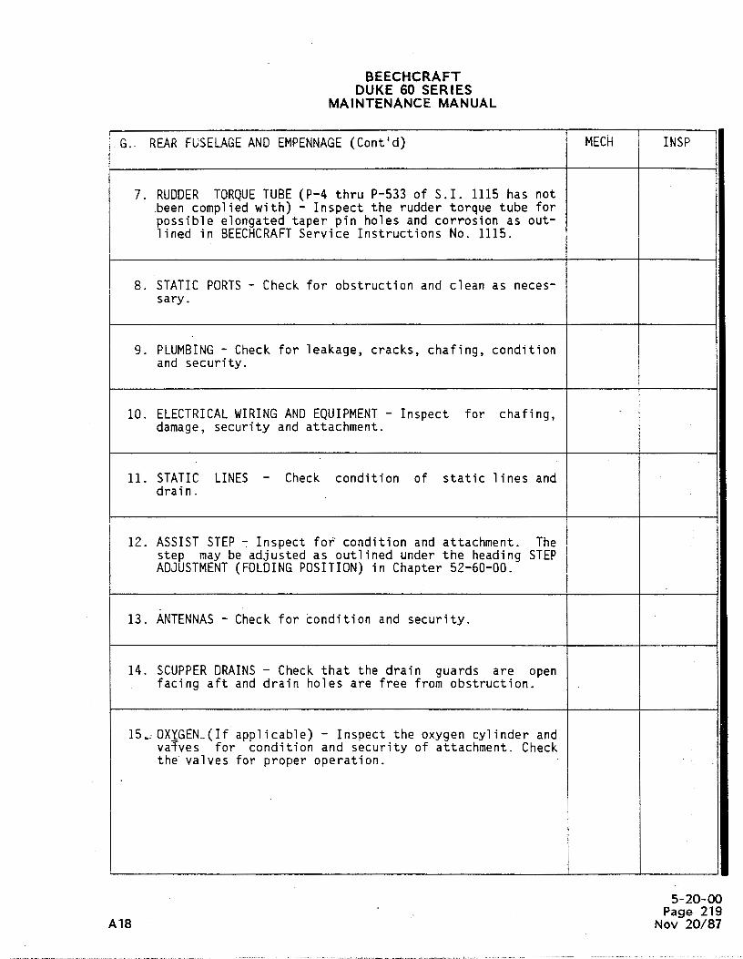
BEECHCRAFTDUKE 60 SERIES
MAINTENANCE MANUAL
G.- REARFUSELAGEANDEMPENNAGE(Cont'd) MECH INSP
7. RUDDER TORQUETUBE (P-4 thru P-533 of S.I. 1115 has not.been complied with) - Inspect the rudder torque tube forpossible elongated taper pin holes and corrosion as out-lined in BEECHCRAFTService Instructions No. 1115.
8. STATIC PORTS- Check for obstruction and clean as neces-sary.
9. PLUMBING- Check for leakage, cracks, chafing, conditionand security.
10. ELECTRICALWIRINGANDEQUIPMENT- Inspect for chafing,damage, security and attachment.
11. STATIC LINES - Check condition of static lines anddrain.
12. ASSIST STEP - Inspect for' condition and attachment. Thestep may be adjusted as outlined under the heading STEPADJUSTMENT(FOLDINGPOSITION) in Chapter 52-60-00.
13. ANTENNAS- Check for condition and security.
14. SCUPPERDRAINS- Check that the drain guards are openfacing aft and drain holes are free from obstruction.
15, OXYGEN-(If applicable) - Inspect the oxygen cylinder andvaTves for condition and security of attachment. Checkthe valves for proper operation.
I
5-20-00Page 219
A18 Nov 20/87

BEECHCRAFTDUKE 60 SERIES
MAINTENANCE MANUAL
H. MAIN GEARANDBRAKES MECH INSP
L R
1. BRAKES, LINES, LINING ANDDISCS - Check for condition,wear and security. Check lines for chafing and signs ofleakage or cracks. Check discs for wear or warping.Check brake discs for cracks.
2. WHEELSANDTIRES - Check wheels for cracks and tires forwear, damage, condition and proper inflation. Checkwheel bearings for condition and wear.
3. LANDING GEARSTRUTS - Inspect the shock struts and com-ponents for cracks, attachment, corrosion, properinflation and evidence of leakage.
4. ACTUATING LINKAGE- Check for wear and cracks at attachpoints. Check for condition and security.
5. GEARDOORSANDLINKAGE- Check doors for damage andcracks to the structure and skins. Check linkage forwear and cracks at the attach points. Check for condi-tion and security. Determine that all clevis retainingpins are in place and secured with cotter pins.
6. STRUTFLUID LEVEL - Check and maintain the properhydraulic fluid level in the struts as outlined in Chap-ter 12-20-00.
7. STRUT AND A-FRAMEHINGE BOLTŠ- Inspect for cracks andsecurity of attachment.
I. NOSEßllAR_ _MECH INSP
1. WHEELANDTIRE - Check wheel for cracks and tire forwear, damage, condition and proper inflation. Checkwheel bearings for condition and wear.
5-20-00Page 220Nov 20/87
· All

BEECHCRAFTDUKE 60 SERIES
MAINTENANCE MANUAL
I. NOSE GEAR(Cont'd) MECH INSP
2. LANDINGGEARSTRUT- Inspect the shock strut and compo-nents for cracks, attachment, proper inflation and evi-dence of leakage.
3. ACTUATINGLINKAGE- Check for wear at attach points.Check for cracks and security.
4. GEAR .DOORS AND LIKKAGE - Check doors for damage andcracks to the structure and skins. Check linkage forwear and cracks at the attach points. Check for condi-tion and security.
5. NOSE GEAR STEERING LINKAGE - Inspect linkages fortightness, condition and security. Check linkage bootsfor condition.
6. SHIMMYDAMPER- Check for condition and attachment.Check attach points for cracks. Check fluid level asoutlined in Chapter 12-20-00.
7. STRUTFLUID LEVEL - Check and maintain the properhydraulic fluid level in the strut as outlined in Chap-ter 12-20-00.
8. STRUTANDA-FRAMEHINGE BOLTS - Inspect for cracks, cor-rosion and security of attachment.
9. NOSEGEARUPLOCKPIN - Remove and inspect for corrosion.Lubricate with MIL-G-81322 prior to reinstallation.
10. NOSEGEARASSEMBLY(P-3 thru P-296) - After the first1000 flight hours and each 1200 flight hours thereafter,inspect the nose gear assembly as noted in BEECHCRAFTService Instructions No. 0669-206, Rev I (or subse-quent).
5-20-00Page 221
A18 Nov 20/87

BEECHCRAFTDUKE 60 SERIESi
MAINTENANCE-MANUAL
J. LANDINGGEAROPERATION MECH INSP
CAUTION
Under no circumstances should the landinggear be operated electrically whil.e thehandcrank is engaged. In the event of suchan operation, a teardown and magneticinspection should be performed for damage toengagement slot in worm shaft.
NOTE
Since the battery voltage is not sufficientto properly cycle the landing gear for thisinspection, use only an external power sourcecapable of delivering and maintaining 28.25±.25 VDC, to the airplane's electrical systemthroughout the extension and retractioncycles when performing the landing gearretraction inspection. For more:specificinformation which may be necessary to accom-plish the following items, refer to Chapter32-30-00.
1. LANDINGGEARACTUATORASSEMBLY- With the airplane onjacks and the retraction cycle started enough to breakthe downlock tension, apply a sharp load by hand in anaft direction against the nose gear strut. If thiscauses the main gear wheels to move approximately 1/2 to1 inch, it is a good indication that the gear actuatorassembly needs overhaul and/or adjustment. °
2. LANDING GEAR GEARBOXANDACTUATINGLINKAGE- Check forleakage, wear, condition and attachment. Check for unu-sual noise. Check oil level by engaging and turning theemergency handcrank 1/2 turn to determine that oil isbeing picked up on the worm gear. The oil level shouldbe maintained no more than necessary to cover 1/2 of thediameter of the worm gear. Check actuator gearbox, motorand switches for leakage, condition and security.
3. DOORS- Check door operation, fit and fair. Check forunusual noise.
5-20-00Page 222Nov 20/87 A1

BEECHCRAFTDUKE 60 SERIES
MAINTENANCE MANUAL
J. LANDINGGEAROPERATION (Cont'd) MECH INSP
4. GENERAL OPERATION- Cycle the landing gear while check-ing to ascertain that the position light switches oper-ate in conjunction with the landing gear position. Checkthe condition and operation of the complete landing gearsystem as outlined in Chapter 32-30-00.
5. POSITION LIGHTS - Check for security, adjustment, wiringfor breaks, condition of insulation, loose connectionsand proper indication. .
6. EMERGENCYEXTENSION- Check system for freedom of opera-tion and positive engagement of the downlocks. Check forunusual noise.
7. LIMIT SWITCHRIGGING- Check for security and properadjustment of the limit switches. Refer to Chapter32-30-00 for correct landing gear gearbox internalclearance.
8. DYNAMICBRAKING ACTION - Verify proper operation ofdynamic brake relay.
9. WARNINGHORN- Check for proper operation.
NOTE
Downlock tension should be checked at thefirst 100-hour inspection and every 200 hoursthereafter.
I
10. UPLOCK- CABLETENSION - Check uplock cable mechanism forcondition and security. Check uplock cable for propertension and for possible fraying.
| 11. DOWNLOCK TENSION (MAIN GEAR) - Check for properdeflection force on the main gear knee joints.
5-20-00Page 223
A18 Nov 20/87

BEECHCRAFTDUKE 60 SERIES
MAINTENANCE MANUAL
J. LANDINGGEAROPERATION (Cont'd) MECH INSP
12. DOWNLOCKTENSION(NOSE GEAR) - Check the downlock ten-sion on the nose gear as outlined in Chapter 32-30-00.
13. UPLOCKROLLERS- Check condition and clearance of uplockrollers per Chapter 32-30-00 and lubricate as outlinedin Chapter 12-20-00. Check for binding.
14. SAFETYSWITCH- Check for secu.rity, proper rig and oper-ation.
15. NOSEGEARUP TENSION - Check the up tension on the nosegear per Chapter 32-30-00.
16. NOSEGEARSTEERING- Check for condition and security.
K. GENERAL MECH INSP
1. Airplane cleaned and serviced.
2. Airplane lubricated, after cleaning, as cutlined inChapter 12-20-00 and BEECHCRAFTSafety Communique No. 57dated June 3, 1981.
3. Inspect all placards to assure that they are easilyreadable and securely attached.
4. Assure -that. all Airworthiness Directives, BEECHCRAFTService Bulletins and previously issued ServiceInstructions are reviewed and complied with as required.
For a complete or annual inspection of the airplane, allitems on the airplane that are noted in this guideshould be inspected.
5-20-00Page 224Nov 20/87 A18

BEECHCRAFTDUKE 60 SERIES
MAINTENANCE MANUAL
PILOT'S DISCREPANCIES REMARKS
iI
5-20-00Page 225
A18 Nov 20/87

BEECHCRAFTDUKE 60 SERIES
MAINTENANCE MANUAL
PILOT'S DISCREPANCIES REMARKS
5-20-00Page 226Nov 20/87 Alf

BEECHCRAFTDUKE 60 SERIES
MAINTENANCE MANUAL
PROPELLER DEICER SYSTEM c. Remove the spinner dome and openINSPECTION all access doors pertaining to the wiring
and components of the deicer system. TurnThe various components of the propeller the deicer switch ON and station andeicer system should be inspected every assistant in the pilot's compartment to50 hours for the appearance of defects. observe the system ammeter. Flex allThe following inspection may provide a accessible wiring, particularly the leadmeans of detecting and correcting such straps, leads from the slip ring assembly,defects before they render the deicer and the firewall electrical connectors andsystem inoperative. their wiring. Any movement of the ammeter,
other than the cycling flicker that mayELECTILIC PROPELLER DEICER (50-HOUR occur when the step switch of the timerG'UIDE) cycles, indicates a short or open circuit
that must be located and corrected.a. Lock the brakes and operate the
engines at near takeoff power. Turn the d. To extend the life of the leaddeicer system switch ON and observe the strap between the hub clamp and clip,ammeter for at least 2 minutes. If the reposition the bend at least 1/2 inch fromammeter needle does not rest within the the existing location of the bend.shaded band (except for a flicker that mayoccur when the step switch of the timer e. Check for damaged springs, andcycles) refer to the troubleshooting chart worn or damaged brushes.in Chapter 30-60-00 for the probablesources of trouble. ELECTRIC PROPELLER DEICER
(100-IEJUR GlJIDE)NOTE
a. Check for radio noise or compassTimers with electronic stepping interference by operating the engines atcircuits may not "flick" notice- near takeoff power with the radio gearably between cycles. turned ON. If, under these conditions,
noise or interference occurs when theb. With the engine shut down, turn deicer systems switch is turned ON and
the deicer switch ON and feel the deicer disappears when the switch is OFF, referboots on the propeller for the proper to the troubleshooting chart for thesequence of the heating elements. The probable source of trouble.presence of local hot spots indicatesdamage to the heating elements, which b. Check all clamps, clips,should be repaired before more serious mountings, electrical connections, anddamage develops. connectors for tightness and electrical
soundness. Check also for loose, broken,C3dTTION or missing safety wire.
When following the instructions c. Closely check deicer boots forof step "b", move the propeller wrinkles, loose, or torn areas, partic-back and forth to prevent arcing u1arly around the outboard end and at thebetween the brushes and the slip point where the strap passes under the hubring_. _ clamp. Look for abrasions or cuts along
the leading edge of the flat or thrustWARNING face. If the heater element wires are
exposed in the damaged areas or if theBefore moving the propeller, make rubber is found to be tacky, swollen, orcertain that the ignition switch deteriorated (as from contact with oil oris OFF and that the engine has solvent fluids), replace the boot.cooled completely. There isalways some danger of a cylinder d. Check that the hub clamps arefiring when a propeller is moved. tight. Inspect for cracks or other damage.
Check to see that the cushioning materialis not missing or damaged in the area
5-20-00Page 227
A18 Nov 20/87

BEECHCRAFTDUKE 60 SERIES
MAINTENANCE MANUAL
under the hub clamp or on the edge of the thrust bearing plate and mounting brackespinner dome. Manually operate the until the brush is properly located.propeller from low pitch to high pitchwhile checking that the deicer lead straps j. Estimate the contact angle of thdo not come under tension. brush block in reTation to the slip rings
If this angle is not approximately-e. Check the slip rings for gouges, degrees, loosen the mounting bolts at
roughened surfaces, cracks, burned or reposition the brush block until ttdiscolored areas, and for deposits of oil, proper angle exists between the brusgrease, or dirt. Clean greasy or contam- block and slip rings. It should be noteinated slip rings with PD680 solvent (15, that the spacing established in step "iChart 207, 91-00-00). After such cleaning, must also be maintained after proper cona run-in time of five hours of engine tact angle is obtained.operation must be allowed before thedeicer system is turned on. k. With the deicer system operatin
and a man in the pilotas compartmenf. If uneven wear or wobble is observing the ammeter, visually inspec
detected, check the alignment of the slip and physically flex the wiring from thrings to the propeller shaft with a dial brush block to each component of toindicator. While turning the propeller to defcer system and to the airplane powecheck .the slip ring alignment, push in on supply. Jumps of the ammeter needle, othethe propeller to eliminate play in the than the momentary flicker that may occtpropeller thrust bearing. If the runout when the step switch of the timer-cyclesover 360 degrees of rotation is over .005 indicate loose or broken wiring in ttinch, or if over any 4-inch are it exceeds area under examination at the moment. I.002 inch, refer to step "h". such instances, continue to flex the wir
ing in the area that- first indicateg. Examine the brush mounting brack- trouble while checking the continuit
ets and housing for cracks, deformation, through the individual wires of ttor other indications of damage. Check for affected harness until the source ctight connections and that the leads are trouble is located. Use the applicablnot chafed or binding. Wiring Diagram Manual to trace the circe
ttry of the deicer system.h. Check to see that each brush rides
on its slip ring over 360 degrees of.
CÄUTIONrotation. If the brush is not properlyaligned, raise or lower the brush block While following the instructionsto the proper position. If the brushes of step "k", move the propellerride both high and low with respect to the back and forth to prevent arcingslip rings in 360 degrees of rotation, the between the brushes and the slipslip ring is eccentrically mounted and the ring.shaft clamp or slip ring must be replaced.
WARNINGi. Check for proper spacing between
the brush block and slip rings. If this Before moving the propeller, makedistance is not within the specified lim- certain that the ignition switchits, loosen the .mounting screws and repo- is OFF and that the engine hassition them.in_the elongated holes until cooled completely. There isthe block is properly positioned. If nec- always some danger of a cylinderessary, shims can be added between the firing when the propeller is
moved.
"END"
5-20-00Page 228Nov 20/87
Al

BEECHCRAFTDUKE60 SERIES
MAINTENANCEMANUAL
CHAPTER 6
LIST OF PAGE EFFECTIVITY
CHAPTERSECTIONSUBJECT PAGE DATE
&EFFECTIVITY/CONTENTS 1 Nov 2/73
00-00 1 Nov 2/732 Nov 2/73
CHAPTER 6 - DIMENSIONS AND AREAS
TABLE OF CONTENTS
CHAPTERSECTION
SUBJECT SUBJECT PAGE
DIMENSIONS AND AREAS &00-00 1Description and Operation 1
Aircraft Dimensions 1Stations Diagram 2
"E ND"
6-EFFECTIVITY/CONTENTSPage 1
Nov 2/73

BEECHCRAFTDUKE60 SERIES
MAINTENANCEMANUAL
17 00
39 3 25
74.00 DIA
1124"
12 3.75
10" / A
9'2.37"
33 10 "60-607-¡A
Aircraft DimensionsFigure 1
6-00-00Page 1
Nov 2/73

BEECHCHAFTDUKE60 SERIES
MAINTENANCElufANUAL
10 00 45 18 81 a 100.0 RK.95 127.12 128.62 146 50 i T5 187 00 201 00 214 .00 265 00 00 306 421 311 ISO 335 0
W LGO
25 00 57.40 67 00 LOS.W 110 00 12T.50 13LOG 148.00 IT3 50 W.L 16.W 333 OL
FUSELAGE
29.375
40.340 35.301
L13.tT2 59,000 4T.000 4.31523 881
129.T 583 I 0 55 500 ogg 21.T50
226 188113 125
-FRONT SPAR FtJS STA138.00
-REAR SPAR FAUS3STA
WING
12. G0g 0 000
L 1508
los.sta so.Teo
W. L ISS. 54-rus sta
336.939
es. .menan
53 020 12 2M FUS STA
HORR0NTALSTABILEER VERTKËSTABILEER60.603.10
Stations DiagramFigure 2
00-00Page 2 "END"Nov 2/73

BEECHCRAFTDUKE60 SERIES
MAINTENANCEMANUAL
CHAPTER 7
LISTOF PAGE EFFECTIVITY
CHAPTERSECTIONSUBJECT PAGE DATE
7-EFFECTIVITY/CONTENTS 1 Oct 27/75
74)O-00 1 Oct 27/75
CHAPTER 7 - LIFTING AND SHORING
TABLE OF CONTENTS
CHAPTERSECTION
SUBJECT SUBJECT PAGE
LIFTING AND SHORING 7-00-00 1Description and Operation . 1
Jacking 1
"END"
7-EFFECTIVITY/CONTENTSPage 1
Oct 27/75
BEECHCRAFTDUKE 60SERIES
MAINTENANCEMANUAL
LIFTING AND SHORING - DESCRIPTION AND ground. Each jack pad is identified and located on theOPERATION under side of the fuselage. One jack pad is located on each
lower wing-to-fuselage attachment fitting along the rearJA CKING spar. The forward jack pad is located in the middle of the
fuselage just aft of the nose gear wheel well.
I CAUTION The Model 400 service jack and three adapters (P/N60-590013 on P-3 through P-61, 60-590013-1, P-62 and
Prior to Jackingthe airplane, ensure that an after) are designed to be used with this airplane.unbalanced condition does not exist. Fuelshould be distributed evenly in both wings to When one engine or one wing is to be removed, a standprevent an unbalanced condition which could should be placed under the opposite wing and the tail tocause the airplane to be unstable while on jacks. counteract the resulting unbalanced condition of the
airplane. Individual main wheels may be jacked by placing aA three-point Jack is used to lift the airplane off the floor jack under the jacking point located under each axle.
"END"
7-00-00Page 1
Oct 27/75

BEECHCRAFTDUKE60SERIES
MAINTENANCEMANUAL
CHAPTER 8
LIST OF PAGE EFFECTIVITY
CHAPTERSECTION.SUBJECT PAGE DATE
8-EFFECTIVITY/CONTENTS 1 Nov 2/73
8-00-00 201 Nov 2/73
CHAPTER 8 - LEVELING AND WEIGHING
TABLE OF CONTENTS
CHAPTERSECTION
SUBJECT SUBJECT PAGE
GENERAL 8-0040 201Maintenance Practices 201
Leveling 201
"END"
8-EFFECTIVITYlCONTENTS
Page 1Nov 2/73

BEECHCRAFTDUKE60SERIES
MAINTENANCEMANUAL
GENERAL - MAINTENANCE PRACTICES d. Inflate or deflate the nose gear shock strut asnecessary to pass the cord through the center of a second
LE VELING Ievel point directly below.
The aircraft may be leveled longitudinally as follows: NOTE
a. Remove the phillips head screw from the upper Suspending the plumb bob in a can of lightlevel point, located just aft of the cabin door. engine oil will assist in stabilizing it.
b. Install a screw, approximately three inches long, inthe upper level point nutplate. Lateral leveling is accomplished by placing a bubble level on
c. Attach a cord and plumb bob to the outboard end the rear spar and deflating the tire or shock strut on theof the screw installed in step "b". high side of the aircraft to center the bubble.
"END"
84040Page 201Nov 2/73

BEECHCRAFTDUKE80 SERIES
MAINTENANCEMANUAL
CHAPTER 9
LIST OF PAGE EFFECTIV/TY
CHAPTERSECTIONSUBJECT PAGE 0ATE
9-EFFECTIVITY/CONTENTS 1 Nov 2/73
9-00-00 201 Nov 2/73
CHAPTER 9 - TOWING AND TAXilNG
TABLE OF CONTENTS
CHAPTERSECTION
SUBJECT SUBJECT PAGE
GENERAL 9-00-00 201Maintenance Practices 201
"END"
9-EFF ECTIVITY/CONTENTSPage 1
Nov 2/73
BEECHCRAFTDUKE60 SERIES
MAINTENANCEMANUAL
GENERAL - MAINTENANCE PRACTICES placarded on the nose gear to prevent damageto the gear.
Attach the hand towbar to the tow lug on the nose gearlower torque knee. CAUTION
Do not push on propeller or control surfaces.CAUTION Do not place your weight on the horizontal
stabilizers to raise the nose wheel off theWhen towing with a tug, observe turn limits as ground.
"END"
940-00Page 201
Nov 2/73

BEECHCRAFTDUKE60SERIES
MAINTENANCEMANUAL
CHAPTER 10
L/STOF PAGE EFFECTIVITY
CHAPTERSECTIONSUBJECT PAGE DATE
10-EFFECTIV1TY/CONTENTS 1 Nov 2/73
10-00-00 1 Nov 2/73
CHAPTER 10 - PARKING AND MOORING
TABLE OF CONTENTS
CHAPTERSECTION
SUBJECT SUBJECT PAGE
GENERAL 10-00-00 1Description and Operaton 1
Parking 1Mooring 1
"END"
10-EFFECTIVITYlCONTENTS
Page iNov 2/73

BEECHCRAFTDUKE60SERIES
MAINTENANCEMANUAL
GENERAL - DESCRIPTION AND OPERATION on the lower aft fuselage. To moor the airplane, chock thewheels fore and aft, install the control lock and tie down
PARKING the aircraft with a nylon fine or chain of sufficient strengthat each mooring eye. Avoid overtightening the rear line,
The brakes are set for parking by pulling out the parking which pulls the nose up so that wind will create higher liftbrake control and depressing the pilot's brake pedals to on the wings. If bad weather is anticipated, it is advisable topressurize the system. Do not attempt to lock the parking nose the airplane into the wind.brake by applying force to the parking brake handle; itcontrols a valve only, and cannot apply pressure to thebrake master cylinders. NOTE
Do not set the parking brakes during lowMOORING temperatures when an accumulation of
moisture may cause the brakes to freeze, orThree mooring eyes are provided; one in each wing and one when they are hot from severe use.
"END"
10-00-00Page 1
Nov 2/73
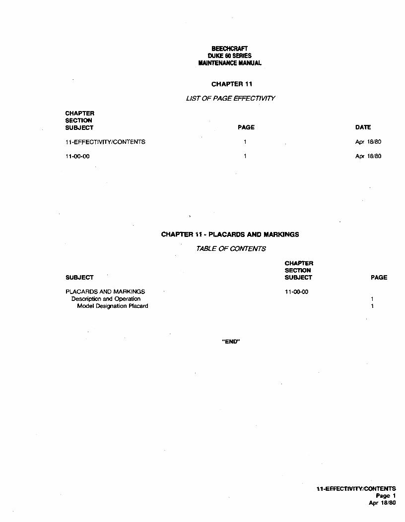
BEECHCRAFTDUKE60 SERIES
MAINTENANCEMANUAL
CHAPTER 11
LIST OF PAGE EFFECTIVITY
CHAPTERSECTIONSUBJECT PAGE DATE
11-EFFECTIVITY/CONTENTS 1 Apr 18/80
11-00-00 1 Apr 18/80
CHAPTER 11 - PLACARDS AND MARKINGS
TABLEOF CONTENTS
CHAPTERSECTION
SUBJECT SUBJECT PAGE
PLACARDS AND MARKINGS 11-00-00Description and Operation 1
Model Designation Placard 1
"END"
it-EEFECTLVITY/CONTENTSPage 1
Apr 18/80

BEECHCRAFTDUKE60 SERIES
MAINTENANCEMANUAL
PLACARDS AND MARKINGS - DESCRIPTION AND in any correspondence to Beech Aircraft Corporation.OPERATION
MODEL DESIGNATION PLACARD NOTE
The modei designation placard is located on the left side of Ascertain that all placards are in place andthe fuselage adjacent to the inboard end of the flap. The legible whenever the airplane has beenflaps must be lowered to observe the placard. The placard repainted or touched up after repairs. Replaceidentifies the airplane by its model number and serial any placards that have been inadvertentlynumber. Should a question arise concerning the care of the defaced after such repainting or repairs.airplane, it is important to include the airplane serial number
"END"
11-00-00Page 1
Apr 18/80

BEECHCRAFTDUKE60 SERIES
MAINTENANCEMANUAL
CHAPTER 12
LIST OF PAGE EFFECTIVITY
CHAPTERSECTIONSUBJECT PAGE DATE
12-EFFECTIVITY 1 Jan 9/86
12-CONTENTS 1 Nov 30/83
12-00-00 1 Oct 19/77
12-10-00 201 Jan 9/86202 Jan 9/86202A Jan 9/86203 Nov 2/73204 Nov 2/73205 Nov 2/73
12-20-00- · 201 May 12/78202 May 12/78202A May 12/78203 Apr 18/80204 Nov 2/73205 Nov 30/83206 Nov 30/83207 Nov 30/83208 Nov 30/83209 Nov 30/83210 Nov 30/83211 Nov 30/83212 Nov 30/83212A Nov 30/83212B Nov 30/83213 Feb 22/80214 May 30/75215 Nov 2/73216 May 30/75217 May 30/75218 May 30/75219 May 30/75220 May 30/75221 Nov 2/73222 Nov 2/73223 Nov 2/73224 Oct 27/75225 Oct 27/75226 Nov 2/73227 Nov 30/83228 Oct 27/75
"END"
12-EFFECTIVITYPage i
A17 Jan 9/86

BEECHCRAFTDUKE60SERIES
MAINTENANŒMANUAL
CHAPTER 12 - SERVICING
TABLEOF CONTENTS
CHAPTERSECTION
SUBJECT SUBJECT PAGE
GENERAL 12-00-00 1Description and Operation 1
REPLENISHING 12-10-00 201Maintenance Practices 201
Filling the Fuel Cells 201Draining the Fuel System 201Engine Fuel Filters and Screens 201Oil System 201Changing the Oil Filter 202Brake System 202Air Conditioning System 202Charging the Air Conditioning System 202Checking Compressor Oil Level 203Evaporator Air Filter Replacement 204Compressor Belt Tension Adjustment 204Heating System 204Heater Spark Plug 204Oxygen System 205
SCHEDULED SERVICING 12-20-00 201Maintenance Practices 201
Tires 201External Power 201Battery 201Deice Boots 202Shock Struts 202Propeller Blade Bearing Lubrication 202Propeller Servicing Points 202APropeller Accumulator 202AInduction Air Filter 203Roton Locks 203Cleaning and Waxing the Airplane Finish 203Cleaning Plastic Windows 204Chart 201 Thread Lubricants 204Clot 202 Consumable Materials 205Chart 203 Servicing 212AChart 204 Lubrication Schedule 214
- Fuselage Access Openings 222Wing Access Openings 224Special Tools 226
"END"
12-CONTENTSPage t
A14 Nov ©

BEECHCRAFTDUKE60 SERIES
MAINTENANCEMANUAL
GENERAL - DESCRIPTION AND OPERATION applicable following chapters. For overhaut procedures forcomponents of a system refer to the BEECRCRAFT Duke 60
The information in this chapter pertains to general servicing Beech Manufactured Components Maintenance Manual, P/Nprocedures and maintenance practices used when servicing 60-590001-27. For electrical wiring diagrams refer to thethe various systems of theairplane -Detailed maintenance BEECHCRAFT Duke 60 Wiring Diagram Manual, PIN 60-information pertaining to these systems will be found in the 590001-29.
"END"
12-0040Page 1
Oct 19/77

BEECHCRAFTDUKE60SERIES
MAlNTENANCEMANUAL
REPLENISHING - MAINTENANCE PRACTICES producing sparks.d. Do not insert the fuel nozzle more than 3 inches
FILL/NG THE FUEL CELLS into the filler neck; to do so may cause damage to the rubberfuel cell.
NOTE DRA/N/NG THE FUEL SYSTEM
Because the deice boots are made of soft flex- To ensure that all fuel is removed from the system, the fuelible material, care must be exercised against should be drained through the boost pumps. To expedite thedragging gasoline hoses over them or resting defueling operation, the boost pumps may be used to pumpladder or platforms against the surface of the the fuel out of the system. The following steps must beboots. accomplished before energizing the pumps:
a. Apply extemat power to the airplane electricalThe fuel system installation consists of an inboard main fuel system.ceit and an outboard cell inthe leading edge, a nacelle tank, b. Place the fuel selector valve in the ON position anda wing panel fuel cell in each wing and a wet wing tip tank the mixture lever in the IDLE CUT-OFF.(optional on serials P-348, P-365 and after). AIIof the fuel c. Remove the filler caps to vent the system.cells in each wing and wing tip are interconnected in order to d. Disconnect the fuel line at the firewall and attach amake all ofthe usable fuel in each wing available to its engine drain hose. Provide a suitable container for the fuel.when the fuel selector valve is turned ON. The interconnect- e. Energize the boost pumps.ing fuel cells are serviced either through the single filler on f. When fuel is no longer pumped from the airplane,each wing or the filler in each of the optional wet wing tips, open the sump drains to complete the defueling operation.providingsingle point fillingfor each side. The fuel sight gage(P-402 and after) located outboard of each naceite may be ENGINE FUEL F/LTERS AND SCREENSused for partial filling of the fuel system, or for balancing thefuel load, when the fuel load is within the range of this gage Most fuel injection systern malfunctions can be attributed to(40 to 60 gallons for each wing). The combined capacity of contaminated fuel. Inspecting and cleaning the fuel strainersthe standard and optionaf system is shown below: should be considered to be of the utmost importance as a
regular part of preventive maintenance.SERIALS CAPACITY USABLE
IN GALLONS IN GALLONS Normally the fuel strainers should be inspected and cleanedevery 100 hours. However, the strainers should be inspected
P-3 thru P-195 and cleaned at more frequent intervals depending on serviceinboard leading 207 192 conditions, fuel handling equipment, and when operating inedge fuel cells localitites where there is an excessive amount of sand orunbaffled dust.
P-3 and after Open each of the seven snap-type fuel drains daily to allowwith inboard leading 207 202 condensed moisture to drain from the system. On the option-edge baffled fuel al system (P-348, P-365 and after) open the fuel drain in thecells wet wing tip using the special tool PIN 101-590020-1.
Optional fuelsystem P-348, 237 232 NOTEP-365 and after
if the cells are to remain unfilled for 10 days orWhen fillingthe airplane fuel cells, always observe the follow- more, apply a thin coating of light engine oil toing: the inside surface of the cellto prevent deteriora-
tion and cracking.
I a. Service the fuel cells with grade 100 (blue) or100LL (green) fuel or if not available, use 115/145 octanefuel (1, Chart 202, 12e20-00)- OIL SYSTEM
b. Make sure the airplane is statically grounded to theservicing unit. The engines are equipped with a wet sump, pressure type oil
c. Do not fill fuel cells near open flame or within 100 system. Each engine sump has a capacity of 13 quarts. Thefeet of any open energized electrical equipment capable of oil system may be checked through access doors in the
12-10-00
A17 Page 201Jan 9/86

BEECHCRAFTDUKE60 SERIES
MAINTENANCEMANUAL
engine cowling. A calibrated dip stick attached to the fillercapindicates the oil level. Due to the canted position of theengines, the dip sticks are calibrated for either right or leftengines and are not interchangeable. The oil should be •
changed every 75 to 100 hours under normal operating con-ditions and the oilfilter changed every 50 hours.
I CAUTION
Any Time the oli system has been contaminatedby metal particles, the oil cooler must be re-placed and the oil system flushed to prevent en-gine damage.
All TIO-541series engines are limited to using only MIL-L-22851 ashless dispersant multi-grade oil (2, Chart 202, 12- Brake Fluid Reservoir20-00). Oil equivalent to SAE 50 or SAE 60 above 60°F; Figure 201below 30°F SAE 40 is recommended. However, newly over-hauled engines of this series may be run-in on the test stand she new aluminum ring and O-ring seal which replace ihwith sîngle viscosity, grade SAE 50 oil conforming with MIL- existing rubber gasket. (Refer to Lycoming Service Bulleti-L-6082, (6. Chart 202, 12-20-00). No. 337.)
d. Torque the retainer bolt to 30-35 foot-pounds anThe oildrain is accessible throughthe cowlflap opening. The sáfety.engines should be warmed to operating temperature to as- e. Remove cap (P-3 through P-20) and reinstall thsure complete drainage. fuel fine.
£RAKE SYSTEM
l NOTE Figure 201)
The engine oil must be of the proper viscosity SEake system servicing is limited primarily to maintaining thand meet the requirements of the current Avco hydraulic fluid level in the reservoir. The brake fluid reservoiLycoming specification 301 and Avco Lycoming accessible throughthe forward baggage compartment dooService Instruction 1014K or subsequent. is hinged on the aft frame of the door.
Loosening the screw securing the reservoir to the airplarThe determining.factor for choosing the correct grade of oilis structure allows the reservoir to swing out for easy servicinthe oil inlet temperature observed furing flight;however, inlet Fill the reservoir with MlL-H-5606 hydraulic fluid (13, Chatemperatures consistently near the maximum allowable indi- 202, 12-20-00) to the full mark on the dip stick. Maintacate a heavier oil is needed. Lycoming recommends use of fluid level between "full" and "add" marks. Do not overfithe lightest weight oil that willgive adequate cooling. or detailed information relating to the proper inspectic
and repair procedures for the brake assembly, refer to ttBeech Manufactured Component Maintenance Manus
CHANGING THE OIL FILTER 7/N 60-590001-27.
The oil filter should be replaced every 50 hours. Replace the A/R CONDITIONING SYSTEMfilter as follows.
Servicing the air conditioning system consits of periodicala. Disconnect the fuel line to the inlet side of the checking the refrigerant level, checking compressor oil leve
engine-driven fuel pump. Cap the fuel line (P-3 through P-20) and changing the system air filter. Recharge the system aand push the line down to allow clearance for oil filter outlined under CHARGING THE AIR CONDITIONING SYIremoval. TEM whenever the refrigerant level is low, air has entered th
b. Cut the safety wire and remove the filter housing. system, or components carrying refrigerant are replacelc. After making sure all traces of gasket material and Refrigerant leaks may be detected by inspection with
cement are removed from the oil filter adapter recess, install flameless leak detector.
12-10-00Page 202Jan 9/86

BEECHCRAFTDUKE60 SERIES
MAINTENANCEMANUAL
CHARGING THE AIR CONDITIONING SYSTEM compressor. The abbreviation DISCH or the letter D on thecompressor cylinder head designates the discharge service
When working on a refrigerative air cooling system, observe valve. The word SUCTION or the letter S on thethe following special servicing precautions: compressor cylinder designates the suction serviœ valve.
When charging a completely purged system, charge with 5a. Remember, this is a high pressure system. When pounds of refrigerant. After charging, the sight glass should
disconnecting a line, loosen the fittings just enough to bleed be observed for bubbles or a milky appearance caused by anoff pressure slowly, then disconnect the fitting. insufficient refrigerant level.
b. Whenever a line is disconnected, purge the entiresystem with a vacuum pump operating at the 125 micron If it is necessary to add refrigerant to a partially chargedlevel. system, add refrigerant slowly until a satisfactory condition
c. Use only R-12 refrigerant (17, Chart 202, is observed through the sight glass, then add an additional ¼12-20-00) in this system. Other refrigerants, particularly to ½ pound of refrigerant.those containing methyl chloride, will cause rapiddeterioration of the aluminum compressor components.
d. When servicing the system with refrigerant, avoid NOTEsmoking or working near an open flame. Refrigerant passingover an open flame will produce a highly toxic phosgene After the system has been charged, thegas. compressor oit level should be checked as
outlined under CHECKING COMPRESSORHook the service unit to the connectÌons on the OIL LEVEL.
12-10-00Page 202A
A17 Jan 9/86

BEECHCRAFTDUKE60SERIES
MAINTENANCEMANUAL
CHECKINGCOMPRESSOR OIL LEVEL e. Close the discharge service valve.(Figure 202) f. With both service valves closed, the suction
pressure will slowly rise to about five pounds gage pressure.The compressor oil level should be checked by a qualified g. The remaining pressure is relieved by unscrewingair conditioner man at the following times: the plug for 5 full turns and bleed to zero pressure.
h. Remove the oil plug and 0-ring.a. After the air conditioner has operated for the first i. To place the crank throw in the best position for
time. dip stick insertion, point the keyway on the compressorb. At the beginning of each season's operation. shaft up toward the cylinder head.c. When oil is emitted from the compressor during j. Insert an oil dipstick until the end contacts the
servicing operation, bottom of the crankcase. Remove and measure the oild. After the air conditioning system has been depth.
recharged.e. If a component is replaced.
NOTEThe compressor is charged with Texaco Capella E or SunisoNo. 5 oil (18, Chart 202, 12-20-00). Only thése or A compressor oil level depth of 1.5 to 1.8equivalent oils should be used when adding oil. To check inches is satisfactory. If the oil level is belowthe compressor oil level, use the following procedure: 1.5 inches, add oil per Chart 202, then
remeasure.a. Operate the air conditioner for approximately 15
minutes in which the last 5 minutes should be at low engine CHART 202rpm (1,000 to 1,100}.This allows the oil to accumulate in CHECKING COMPRESSOR OIL LEVELthe compressor for an accurate oil level reading.
b. Attach service gages to compressor service valve Dip Stick Oi! toports.
* Depth (In.) be Added (Oz.)c. With air conditioner operating, slowly close the
suction service valve until the suction pressure gage reads .6 8.0zero or slightly below. .8 6.5
d. Stop the air conditioner and quickly close the 1.0 5.0suction service valve when the suction gage reads a little 1.2 3.0above zero. 1.4 1.5
FINGER RING
33\ -OIL CHECK PLUG(ALSO OTHER SIDE)
60-451-1A
NOTCHES1/10 IN. APART
Dipstick and Compressor Oil Check PlugFigure 202
12-10-00Page 203Nov 2/73
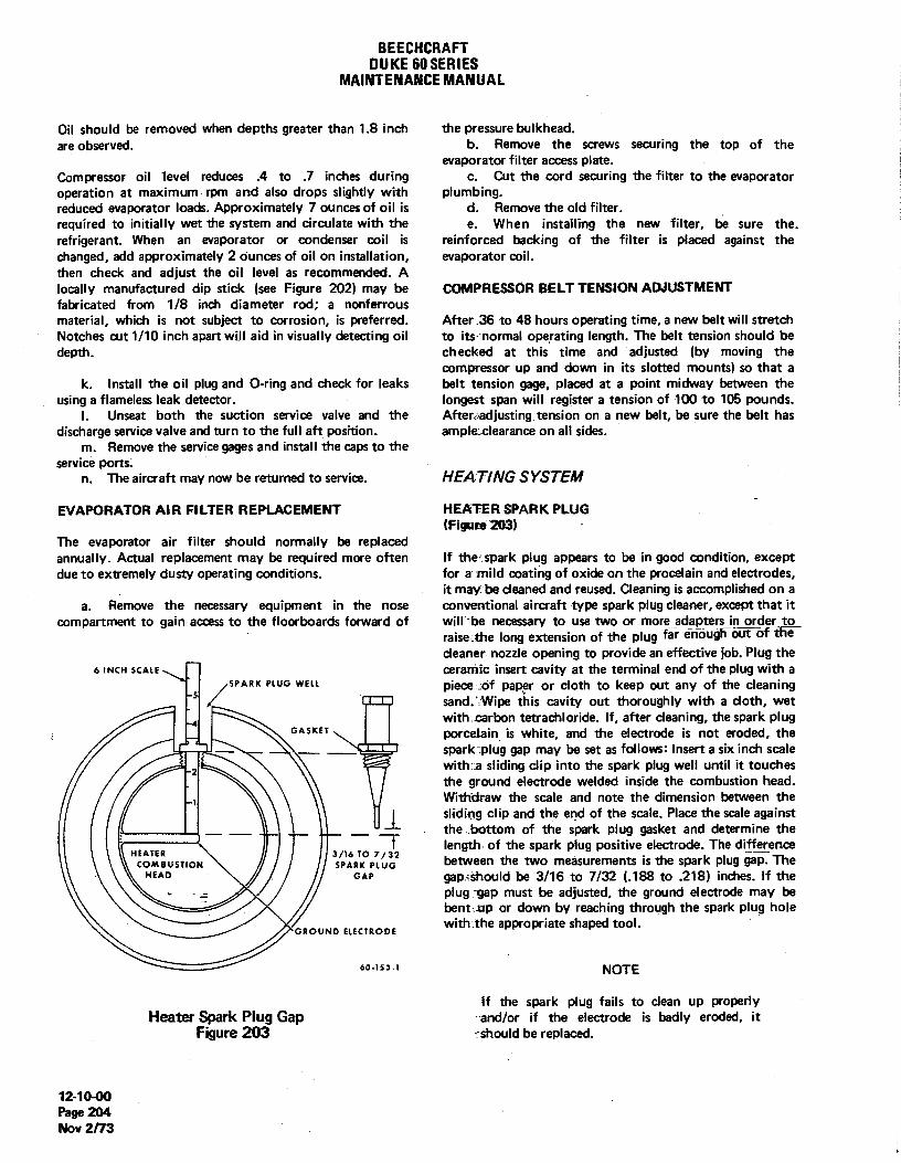
BEECHCHAFTDUKE60SERIES
MAINTENANCEMANUAL
Oil should be removed when depths greater than 1.8 inch the pressure bulkhead.are observed. b. Remove the screws securing the top of the
evaporator filter access plate.Compressor oil level reduces .4 to .7 inches during c. Cut the cord securing the filter to the evaporatoroperation at maximum rpm and also drops slightly with plumbing.reduced evaporator loads. Approximately 7 ounces of oil is d. Remove the old filter.required to initially wet the system and circulate with the e. When installing the new filter, be sure the,refrigerant. When an evaporator or condenser coil is reinforced backing of the filter is placed against thechanged, add approximately 2 ounces of oil on installation, evaporator coil.then check and adjust the oil level as recommended. Alocally manufactured dip stick (see Figure 202) may be COMPRESSOR BELT TENSION ADJUSTMENTfabricated from 1/8 inch diameter rod; a nonferrousmaterial, which is not subject to corrosion, is preferred. After 36 to 48 hours operating time, a new belt will stretchNotches cut 1/10 inch apart will aid in visually detecting oil to its normal operating length. The belt tension should bedepth. checked at this time and adjusted (by moving the
compressor up and down in its slotted mounts) so that ak. Install the oil plug and O-ringand check for leaks belt tension gage, placed at a point midway between the
using a flameless leak detector. longest span will register a tension of 100 to 105 pounds.I. Unseat both the suction service valve and the Afteraadjusting tension on a new belt, be sure the belt has
discharge service valve and turn to the full aft position. ampktclearance on all sides.m. Remove the service gages and install the caps to the
service ports.n. The aircraft may now be returned to serviœ. HEAT/NG SYSTEM
EVAPORATOR AIR FILTER REPLACEMENT HEATER SPARK PLUG(Figum 203)
The evaporator air filter should normally be replacedannually. Actual replacement may be required more often If the spark plug appears to be in good condition, exceptdue to extremely dusty operating conditions. for a mild coating of oxide on the procelain and electrodes,
it may be cleaned and reused. Cleaning is accomplished on aa. Remove the necessary equipment in the nose conventional aircraft type spark plug cleaner, except that it
compartment to gain access to the floorboards forward of will be necessary to use two or more adapters in order toraise the long extension of the plug far enöugh öWöf tWcleaner nozzle opening to provide an effective job. Plug the
6 INCH SCALE COf8tWÎC ÎnSert cavity at the terminal end of the plug with a-5
SPARK PLUG WELL pieCecOf paper Or CIOth to keep out any of the cleaningsand. Wipe this cavity out thoroughly with a cloth, wetwith carbon tetrachloride. If, after cleaning, the spark plug
GASKET POfCei8in ÎS white, and the electrode is not eroded, the.r
_ _ _ spark plug gap may be set as follows: Insert a six inch scalewith a sliding clip into the spark plug well until it touchesthe ground electrode welded inside the combustion head.Withdraw the scale and note the dimension between thesliding clip and the end of the scale. Place the scale againstthe bottom of the spark plug gasket and determine thelength of the spark plug positive electrode. The differenceHEATER 3/16 TO 7/32
COMBUSTION SPARK PLUG between the two measurements is the spark plug gaTTheHEAD GAP gapiShould be 3/16 to 7/32 (.188 to .218) inches. If the
plug gap must be adjusted, the ground electrode may bebent up or down by reaching through the spark plug hole
GROUND ELECTRODEwith the appropriate shaped tool.
60-153-1 NOTE
If the spark plug fails to clean up properlyHeater Spark Plug Gap and/or if the electrode is badly eroded, it
Figure 203 should be replaced.
12-1040Page 204Nov 2/73

BEECHCRAFTDUKE60 SERIES
MAINTENANCEMANUAL
If a new spark plug is being installed, be sure to measure the valve. The system may be fitted with an 11, 22, 49 or 65gap. Do not bend the positive electrode. Torque the spark cubic foot cylinder. When the system is not in use, theplug to 28 foot-pounds. control valve on the console should be shut off to prevent
oxygen loss.
NOTE To recharge the oxygen system, remove the protective capfrom the filler valve.
The spark plug can be checked visually forsparking prior to installing the plug as follows:Disconnect the wire from the terminal on the WARNINGheater wiring side of the terminal strip tode-energize the fuel solenoid valve. Connect the Keep fires, cigarettes and sparks away whenhigh-voltage lead temporarily and lay the spark outlets are in use. Open and close all oxygenplug on the heater jacket. valves slowly. Inspect the filler connection for
cleanliness before attaching it to the filler valve.Keep tools, hands and components clean, as fire
WARNING or explosion may occur when pure oxygenunder pressure comes in contact with organic
Be sure to plug the spark plug hole in the heater material such as grease or oil.to prevent any possibility of residual fuelblowing out and igniting. Do not touch the Attach a hose from an oxygen recharging cart to the fillerspark plug while energized because of valve. To prevent overheating, fill the oxygen system slowlydangerously high voltage. by adjusting the recharging rate with the pressure regulating
valve on the cart. The oxygen cylinder should be filled to apressure of 1800 ± 50 psi at a temperature of 70°F. This
OXYGEN SYSTEM pressure may be increased an additional 3.5 psi for eachdegree of increase in temperature; similarly, for each degree
CAUTION of drop in temperature, reduce the pressure by 3.5 psi.When the oxygen system is properly charged, disconnect
All persons handling and servicing oxygen the hose from the filler valve and replace the protective cap.systems should review proper precautions to be If at any time, in the process of servicing and purging theobserved during servicing. FAA Advisory system or replacing the oxygen cylinder, it becomesCircular 43.13-1 contains the necessary necessary to disconnect a fitting, the threads should beinformation. treated with MIL-T-27730 tetrafluoroethylene tape (Chart
201, 12-20-00). The system should then be checked forleaks with MIL-L-25567 leak testing compound (14, Chart
The oxygen system consists of an oxygen regulator, six 202, 12-20-00). After testing, if no leaks are found, wipeoutlets, a nose or rear mounted cylinder and recharging the system clean and dry.
"END"
12-10-00Page 205Nov 2/73
BEECHCRAFTDUKE60 SERIES
MAINTENANCEMANUAL
SCHEDULED SERVICING - MAINTENANCE PRAC- b. Before connecting the external power unit, tum offTICES - all radio equipment and generator switches, but leave the
battery on to protect transistorized equipment against trans-T/RES ient voltage spikes.
I NOTE CAU710N
"Aero Seal" is a tire additive which is very effec- When the battery switch is tumed off for ex-tive in stopping small leaks and weep-hole leaks tended ground power operation, place an exter-in tubeless tires. The proper procedure for the nal battery in parallel with the output of the exter-use of this additive may be obtained by referring nal power unit before operating any transis-to Service Instructions No. 0916. torized avionics equipment.
c. If the unit does not have a standard AN plug, checkThe nose gear is equipped with a 15 x 6.00 x 6, 4 ply, type VI, the polarity and connect the positive lead from the externaltube type tire. The main gear tires are either 6.50 x 8, 8 ply power unit to the center post and the negative lead to thetubeless, rim-inflated type (P-4 through P-191, except P-190) front post of the airplane's external power receptacle. Theor 19.5 x 6.75 x 8, 10 ply, tube type (P-190 and after, except small pin of the receptacle must be supplied with + 24 vdc toP-191 and those airplanes prior to P-190 which have com- close the extemal power relay that provides protectionplied with Service Instructions No. 0536-202, Rev II).A max- against damage by reverse polarity.imum outside diameter of 15 inches on the nose gear tire isrequired to ensure proper clearance of the nose gear shock BAT7ERYabsorber assembly. Inflate the nose gear tire to 47-50 psi.Inflate the 8 ply main gear tires to 69-75 psi and the 10 ply Airplanes prior to P-446 are equipped with 24 volt, 13.5main gear tires to 76-82 psi. If necessary to comply with ampere-hour batteries. To obtain optimum service from thelanding restrictions, main gear tire inflation may be reduced nickel-cadmium battery, proper and regular maintenance ofto 65 psi for 8 ply tires. Maintaining recommended tire infla- the battery must be performed.tionwill help to avoid damage from landing shock and contactwith sharp stones and ruts, and will minimize tread wear. Serials P-4 through P-225 are equipped with either GeneralWhen inflating tires, inspect them visually for cracks, breaks Electric or Gulton batteries. Serials P-226 through P-445 areor evidence of external damage. equipped with General Electric air cooled batteries.
EX7ERNAL POWER Airplanes, P-446 and after, are equipped with two 25 am-pere-hour, 12 volt, lead-acid batteries connected in series
The airplane electrical system is protected against damage and supplying a total system capacity of 24 volts.from reverse polarity by a relay and diodes in the extemalpower circuit. The extemal power receptacle is located just A Systematic Battery Maintenance Program should be estab-outboard of the left engine nacelle. The receptacle is de- lished and carefully followed:signed for a standard AN type plug. To supply power forground checks and air conditioner operation, a ground power a. The battery should be removed from the airplanesource capable of delivering a continuous load of 300 am- for service.peres at 24 to 30 volts is required. Use of an inadequate b. A log of the services performed on each batteryground power unit can cause a voltage drop below the drop- should be maintained.out voltage of the starter relay, resulting in relay chatter and c. The battery should be removed from the airplanewelded contacTs.By the same token, a maximum continuous and serviced after: 100 Flight Hours or 30 days, whicheverload in excess of 350 amperes will damage the extemal occurs first. If the ambient temperatures are above 90°F orpower relay and power cables of the airplane. Observe the the time between engine starts averages less than 30following precaution when using an extemal power source. minutes, the duty cycle should be reduced.
d. The log of battery services performed should bea. Use only an auxiliary power source that is nega- evaluated to determine the need to service the battery at the
tively grounded. If the polarity of the power source is un- above recommended intervals or to extend the intervals ifknown, determine the polarity with a voltmeter before con- justified. Accurate water consumption data is a valid baro-necting the unit to the airplane. meter to use for adjustment of the servicing intervals.
12-2&40Page 2ol
May 12/78

BEECHCRAFTDUKE60SERIES
MAINTENANCEMANUAL
CAUTION CAUTION
Methods of servicing lead-acid batteries do not Do not unscrew the air valve assembly until theapply for the servicing of nickel-cadmium bat- air pressure has been released or it may beteries. blown off with considerable force, causing injury
to personnel or property damage.
Since the proper servicing of nickel-cadmium batteries re-quires two days, an additional battery (or batteries) will be b. Remove the air valve assembly.required where airplane utilization warrants. For additional c. Compress the strut and fillthrough the air valveinformation on battery maintenance, refer to Gulton Instruc- assembly hole with MIL-H-5606 or MIL-H-83282 hydraulictions for Use and Care of Sintered Plate Vented Nickel. fluid (13, Chart 202) (approximately one pint) until the fluidCadmium Storage Batteries (P/N ABD-1100), or Marathon overflows.Battery Instruction Manual (P/N BA-89), or Operating and d. Cycle the strut (full extension to compressed) andService Manual for General Electric Nickel-Cadmium Ven- refill.Repeat until fluid can not be added to the strut in theted-Cell Batteries (P/N GET-3593A), which ever the airplane compressed position.is equipped with. Advisory Circular AC 00-33, printed byDepartment of Transportation, Federal Aviation Administra-tion, is another good source of battery maintenance NOTEinformation.
Cycling of shock strut is necessary to expel anyDE/CE BOOTS -trapped air within the strut housing.
Because the deice boots and related components operate onclean air supplied from the pressure manifold, little is re- e. Install the air valve assembly.quired in the form of servicing the system. The boots should f. With the airplane resting on the ground and the fuelbe checked for engine oil after servicing and at the end of cells full; inflate the nose gear strut until 4-1/16 to 4-5/16each flight, and any oil found should be removed. This can be inches of the piston is exposed, and inflate the gear strut untilaccomplished by the use of a neutral soap and water solu- 3 inthes of pistion is exposed. Rock the airplane gently totion.Care should be exercised to avoid scrubbing the surface prevent possible binding of the pistion in the barrel whileof the boot as this will tend to remove the special conductive infating.surfacing.
NOTENOTE
It is recommended that the nose strut inflationBecause the deice boots are made of soft flex- dimension and the tire inflation pressure beible material, care must be exercised against carefully adheared to. Properly inflated tires anddragging gasoline hoses over them or resting struts reduce the possibility of ground damageladder or platforms against the surface of the occurring to the propellers. Exercise cautionboots. when taxiingover rough surfaces.
For surface deice boot maintenance, refer to Chapter 30-10- g. The shock strut pistion must be clean. Remove00. foreign material by wiping the strut with a cloth dampened in
hydraulic fluid.SROCK STRUTS -
-
PROPELLER BLADE BEARING LUBRICATIONThe shock struts are filled with compressed dry air or nitro- (Figure 201)
I gen and MIL-H-5606 or MIL-H-83282 hydraulic fluid (13,Chart 202). The same procedure is used for servicing both a. Remove the propeller spinner.the main and nose gear shock struts. The shock strut may be b. Remove the safety wire and covers from the sixserviced as follows: zerks. See Figure 201 for location.
c. Aemove one zerk from each blade.a. Remove the air valve cap and depress the valve d. Lubricate the blade bearings with Hartzell DG
core to release the air pressure. Grease by placing the grease gun fitting on the remaining
12-20-00Page 202May 12/78

BEECHCRAFTDUKE60SERIES
MAINTENANCEMANUAL
zerk of each blade. Fill until the grease is visible in the hole b. Charge the dome with dry air or nitrogen to awhere the opposite zerk was removed. pressure of 80 psi at 70°F. Increase the pressure an addition-
e. Reinstall the zerk on each blade. al 2 psi for every 10 degrees of increase in temperaturef. Clean excess grease from the propeller, reinstall similarly for every 10 degrees of drop in temperature, reduce
the grease zerk covers and safety, the pressure by 2 psi.g. Reinstall the spinner.
PROPELLER ACCUMULATOR
PROPELLER SERVIC/NG POINTS The propeller accumulators are located on the lower rear(Figure 201) section of each engine. The accumulators should be in-
spected every 100 hours and charged with dry air or nitrogena. Remove the access cap from the propeller spinner to 125 psi. If a unit will not hold 70% of its normal charge,
to expose the filler valve. from inspection to the next, it should be replaced.
12-2440P•e• 202 AMay 12/78

BEECHCRAFTDUKE60 SERIES
MAINTENANCEMANUAL
AIR VALVE specified by the manufacturer's instructions stamped on thefilter.
ROTON LOCKS(Figure 202)
Usually, Roton locks will need no service. If there is a
GREASE ZERK GREASE ZERK grinding and binding in the lock as the seat rectines or theretum action becomes jerky, a little grease properly appliedas follows should improve the operation.
a. Apply grease (30, Chart 207, 91-00-00) to thethreads as shown in Figure 202.
b. Compress the spring guide and counter-balancespring approximately one inch.
c. Remove the retaining ring.d. Relax pressure on the spring guide and counter-
- balance spring slowly until the spring is fully extended.e. Remove the lock from the fixture and remove the
spring guide, counter-balance spring, and spring guide tube.f. Apply a small quantity of grease to the completely
oc extended thrust screw.--- o g. Reassemble the lock. For service other than
o lubrication a new lock will need to be purchased.
CLEANING AND WAX/NG THE AIRPLANE F/N/SHe
60 - N 4 BOCSUSe the wax seals the paint from the outside air, a newpaint job should not be waxed for a period of 90 days to
Propeller Servicing Points allow the paint to cure. Wash uncured painted sudaces withFigure 201 only cold or lukewarm (never hot) water and a mild non-
detergent soap. Any rubbing of the painted surface shouldINDUCTION A/R FILTER be done gently and held to a minimum to avoid cracking the(Wet or Dry Element) paint film.
The induction air filter should be cleaned every 50 hours After the paint cures, a thorough waxing will protect paintedand replaced every 500 hours of service. Clean the filter as and unpainted metal surfaces from a variety of
FULLY EXTENDED RETAINING RING
SPRING GUIDE
3/4" (APPROX) - APPLY GREASE(LIGHTLY HERE ONLY)
ABSOLUTELY NO GREASE 'SPRING GUIDE TUBEIN THIS AREA MAIN ASSY
COUNTERBALANCESPRING
60-314-1
Roton LockFigure 202
12-20-00Page 203
Apr 18/80

BEECHCRAFTDUKE60SERIES
MAINTENANCEMANUAL
highly corrosive elements. Flush loose dirt away first with commercial cleaner, follow the instructions on theclear water, then wash the airplane with a mild soap and container.water. Harsh, abrasive, or alkaline soaps or detergentsshould never be used. Use soft cleaning cloth or chamois toprevent scratches when cleaning and polishing. Any good If a commercial cleaner is not available, the followinggrade automobile wax may be used to preserve painted instructions should be followed:surfaces. To remove stubborn oil and grease, use a softcloth dampened with naphtha. After cleaning with naphtha,the surface should be polished and rewaxed. Cleaning of the acrylic plastic windows should never be
atteropted when dry. The window should first be flushedwith water or a mild soap solution, then rubbed slightly
NOTE with a grit-free soft cloth, chamois or sponge. Stubborngrease or oil deposits are readily removed with aliphatic
Frequently inspect the underside of the wing naphtha or hexane. Rinse with clear water.and flaps in the area covered by the engineturbocharger exhaust stream for fuel leaddeposits. If such deposits are discovered, theyshould be removed immediately with a water CAUTIONand mild detergent solution and the surfacerewaxed. Do not use thinner or aromatic abrasive
cleaners to clean the windows as they willCLEANING RLASTIC WINDOWS damage the surface of the plastic. Aliphatic
naphtha and similar solvents are highlyA commercial cleaning compound made specifically for inflammable, and extreme care must beacrylic plastic windows may be used. When using a exercised when used.
CHART 201THREAD LUBRICANTS
The vendor products appearing in this chart have been selected at random tohelp field personnel determine products conforming to the specificationslisted in this publication. The brand names are listed for ready reference andare not specifically recommended by Beech Aircraft Corporation. Anyproduct which conformsto the referenced specification may be used.
SYSTEM MATERIAL SPEC/FICATION VENDOR PRODUCTS
Fuel Petrolatum VV-P-236
Oil, Manifold Pressure, Lubricating Grease (Gas- MIL-G:6032 L-237, Lehigh Chemical Co.Air Pressure oline and Oil Resistant) Chestertown, Maryland
Rockwell 950, Rockwell Mfg.Pittsburg, 8 Pa.
Royco 32, Royal Lubricants Co.Hanover, New Jersey
Deicer, Static, Pitot Anti-Seize, White Lead TT-A-580 Armite Product, Armite Labora-Base tories, Los Angeles, California
Autopilot (Pipe Threads Anti-Seize, White Lead JAN-A-669Only) Base
Brakes Hydraulic Fluid or Anti- MIL-H-5606 orSeize, White Lead Base TT-A-580
12-20-00Page 204Nov 2/73

BEECHCRAFTDUKE60 SERIES
MAINTENANCEMANUAL
CHART 201 (Cont'd)THREAD LUBRICANTS
SYSTEM MATERIAL SPECIFICATIONS VENDOR PRODUCTS
Air Conditioner A nt i - Se i ze , Gr a ph i te MIL-T-5544 orPetrolatum or Anti-Seize, TT-A-580White Lead Base
Oxygen Tetrafluoroethylene Tape MIL-T-27730 Johnson and Johnson Inc.,Permacel Div., U.S. Highway1, New Brunswick, New Jersey00901
Turbocharger Inlet Probe Anti-Seize Compound MIL-A-907D Anti-Seize Compound C5A,Fel-Pro Inc., 7450 McCormick,Skokie, Illinois
CHART 202CONSUMABLE MATERIALS
Only the basic number of each Military Specification is included in the Consumable Materials Chart. No attempt has beenmade to update the basic number with the letter suffix that designates the current issues of the various specifications.
Vendors that are listed as meeting the Federal and Military Specifications are provided as reference only and are notspecifically recommended by Beech Aircraft Corporation; consequently, any product conforming to the specificationlisted maybe used. The products listed below have been tested and approved for aviation usage by Beech Aircraft Corporation, thevendor, or by compliance with the applicable specifications. Other products that are locally procurable which conform to therequirements of the applicable Military Specification may be used even though not specificallyincluded herein.
It is the responsibility of the operatorluser to determine the current revision of the applicable Military Specification prior tousage of that item. This determination may be made by contacting the vendor of a specific item.
ITEM MATERIAL SPECIFICATIONS VENDOR PRODUCTS
1. Fuel, Engine 100/130 octane (If notavailable, use 115/145)Never use 91/96 octane fuel. I
2. Oil, Engine MIL-L-22851 Global Concentrate A(Ashless Dispersant) Delta Petroleum Company Inc.
P.O. Box 10397New Orleans, La. 70121
Paranox 160 and 165Enlay Chemical Company60 West 49th StreetNew York, N.Y. 10020
RT-451, RM-173E, RM-180EMobil Oil Corporation150 East 42nd StreetNew York, N.Y. 10017
12-20-00Page 205
A14 Nov 30/83

BEECHCRAFTDUKE60 SERIES
MAINTENANCEMANUAL
CHART 202 (Cont'd)CONSUMABLE MATERIALS
ITEM MATERIAL SPECIFICATIONS VENDOR PRODUCTS
2. Oil, Engine Shell Concentrate A Code 60068(Ashless Dispersent Aeroshell W120, Aeroshell WSOCont'd.) Shell Oil Company
One Shell PlazaHouston, Texas 77002
TX-6309 Aircraft Engine Oil,Premium AD120, Premium ADSOTexaco inc.135 East 42nd StreetNew York, N.Y. 10017
PQ Aviation Lubricant 753American Oil and Supply Co.238 Wilson AvenueNewark, N.J. 07105
Chevron Aero Oil Grade 120Chevron Oil Co.1200 State StreetPerth Amboy, N.J. 08861
Esso Aviation Oil E-120,Enco Aviation Oil E-120,Esso Aviation Oil A-100,Enco Aviation Oil A-100,Esso Aviation Oli E-80,Enco Aviation Oil E-80Exxon Company, U.S.A.P. O. Box 2180Houston, Texas 77001
Chevron Aero Oil Grade 120Standard Oil Co. of Calif.225 Bush StreetSan Francisco, Calif. 94120
3. Corrosion Preventive MIL-C-6529 Anti-Corrode No. 205,Compound Cities Service Oil Co.
60 Wall Tower, New York 5,N.Y.
Rust Foil No. 652-2Franklin Oil and Gas Co.Bedford, Ohio
Kendex No. 7038, KendallRefining Co., Bradford, Pa.
12-20-00Page 206Nov 30/83 A14

BEECHCRAFTOUKE60 SERIES
MAINTENANCEMANUAL
CHART 202 (Cont'd)CONSUMABLE MATERIALS
ITEM MATERIAL SPECIFICATIONS VENDOR PRODUCTS
4. Lubricating Oil MIL-L-6081 Gulflite Turbojet OilNo. 1010, Gulf Oil Corp.Pittsburg, Pa.
Aeroshell No. 3-1286Shell Oil Co., 50 West50th Street, New York,N.Y. 10020
Jet Engine Oil No. 1010Texaco Inc., 135 East42nd Street, New York,N.Y. 10017
5. Lubricating Oil SAE 20 or SAE 10W30
6. Lubricating Oil, Aircraft MIL-L-6082 Conoco Aero Oil No. 1065Reciprocating (Piston) Continental Oil Co.Engine Ponca City, Oklahoma
Phillips 66 AviationEngine Oil, Grade 1065Phillips Petroleum Co.Bartiesville, Oklahoma
Skilflite No. 100, SkellyOil Co., El Dorado, Kansas
Avrey 10V1100,Socony Mobil Oil Co.Inc., 150 East 42nd StreetNew York, N.Y. 10017
Or any approved aircraftengine oil (gradedat1065 or 1100).
7. Lubricating Oil (Gear) MIL-L-6086 Grade M Trojan Gear Oil No. 6086 M.Cities Service Oil Co.60 Wall Tower, New York 5,N.Y.
Aeroshell Fluid 5 M,Shell Oil Co., 50 West50th Street, New York,N.Y. 10020
L-1195, Sinclair RefiningCo., 600 Fifth Avenue,New York, N.Y.
12-20-00A14
Page 207Nov 30/83

BEECHCRAFTDUKE60 SERIES
MAINTENANCEMANUAL
CHART 202 (Cont'd)CONSUMABLE MATERIALS
ITEM MATERIAL SPECIFICATIONS VENDOR PRODUCTS
8. Lubricating Grease MIL-G-7711(Supersededby MIL-GB1322,see Itemi9)
9 Lubricating Grease MIL-G-87322 Mobilgrease 28Mobil Oil Corporation
I NOTE Shoreham BuildingMIL-G-81322is not compatible with Washington, D.C. 20005Aeroshell No. 5 and contains chemi-cals harmful to painted surfaces. Aeroshell Grease 22
Shell Oil Co., 50 West50th Street, New York,N.Y. 10020
10. Lubricating Grease (Gear) Mobile Compound G.G.
11. Lubricating Grease MIL-G-23827 Supennil Grease(Aircraft and Instruments, No. A72832, AmericanLow and High Temperature) Oil Co., 910 South
Michigan Avenue
I NOTE Chicago, Ill. 60680
Precautions should be taken Royco 27A, Royal Lubri-when using MIL-G-23827and cants Co., River Road,M1L-G-81322,since these greases P.O. Box 95, Hanover,contain chemicals harmful to N.J. 07936painted surfaces.
Shell 6249 Grease,Shell Oil Co., 50 West50th Street, New York 20,N.Y.
12. Lubricant, Molybdenum MIL-M-7866 Molykote Z Wilco Co.Disulfide Powder Wichita, Kansas
Molykote Z StandardOil of Kentucky
Molykote Z,Haskeli Engineeringand Supply Company100 East Graham PlaceBurbank, California 91502
Moly-Paul No. 4. K.S.Paul Products Ltd.Nobel Road, London,England
12-20-00Page 208Nov 30/83 A14

BEECHCRAFTDUKE60 SERIES
MAINTENANCEMANUAL
CHART 202 (Cont'd)CONSUMABLE MATERIALS
/TEM MATER/AL SPEC/FICAT/ON VENDOR PRODUCTS
13. Hydraulic. Fluid MIL-H-5606 Brayco 756D, Bray Oil Co.3344 Medford StreetLos Angeles 63, California
PED 3656, Standard Oil Co.of California,225 BushStreet, San Francisco 20,California
14. Oyxgen-System, Leak MIL-L-25567Testing Compound
15. Solvent, Dry Cleaning or PD680 or BritishWhite Spirit Specification 245 -
16. Lubricating Oil SAE-10
17. Air Conditioner R-12Refrigerant
18. Oil (Air Conditioner Suniso No. 5, VirginiaCompressor) 500 Viscosity Chemical and Smelting Co.
West Norfolk, Virginia
Texaco Capella E,Texaco inc., 135 East42nd Street, New York,N.Y. 10017
19. Aviator's Breathing Oxygen MIL-O-27210
20. Naphtha TT-N-95
21. Methyl Ethyl Ketone MIL-M-13999
22. Toluol (Toluene) TT-T-548
23. Paint Remover Turco No. 4260, TurcoProducts Inc., LosAngeles, Califomia
24. Epoxy Primer Ameron IndustrialCoatings Division,P.O. Box 2153,Wichita, Kansas
25. Wash Primer EX2016G Ameron lndustrialCoatings Division,P.O. Box 2153,Wichita, Kansas
12-20-00
Page 209A14 Nov 30/83

BEECHCRAFTDUKE60 SERIES
MAINTENANCEMANUAL
CHART 202 (Cont'd)CONSUMABLE MATERIALS .
ITEM MATERIAL SPECIFICATIONS . VENDOR PRODUCTS
26. Zinc Chromate Primer MIL-P-8585
27. Rubber Hose MIL-H-5593
28. Oil, Engine Preservative MIL-H-5593
29. Graphite, Lubricating SS-G-659
I(Supersedes
NOTE MIL-G-6711)Lubricating Graphite Supersededby Item 12
30. Lubricating Grease Enco Andok-B Humble Oil Co.Houston, Texas
31. Solvent CRC-2-26, CorrosionReaction ConsultantsLimeklim PikeDresher, Pa.
32. Laminated Glass Cloth MIL-F-9084 Trevano, Coast Manufactur-ing and Supply Inc., Box 71Livermore, Califomia
Uniglass, United Merchantsand Manufacturing Inc.1407 Broadway, New York,New York 10018
33. Resin MIL-R-7575 Laminac 4116, AmericanCyanamid Co., Wallingford,Connecticut
Glidpol 1001, The GliddenCompany, 925 Euclid Ave.Cleveland, Ohio 44114
34. Lubricating Grease Aeroshell 7A Shell OilCo., 50 West50th Street, New York, N.Y.
35. Urethane Primer U.S. Paint Lacquer andChemical Co., 1501 N.Belmont P.O. Box 8151Wichita, Kansas 67208
I Ameron industrialCoating Division,P.O. Box 2153,Wichita, Kansas
12-20-00Page 210Nov 30/83 A‡

BEECHCRAFTDUKE60 SERIES
MAINTENANCEMANUAL
CHART 202 (Cont'd)CONSUMABLE MATERIALS
ITEM MATERIAL SPECIFICATIONS VENDOR PRODUCTS
36. Thread Locking Compound Loctite Sealant, Grade A Loctite Corp.705 N. Mountain RoadNewington, Conn. 06111
37. Penetrating Oil Mouse Milk Worldwide Aircraft FiltersCorp., 1685 Abram Ct.San Leandro, Calif. 94577
Kano Kroil Kano Labratories Inc.Nashville, Tennessee
38. Lubricating Grease MIL-G-3545 Aeroshell Grease 5Shell Oil Co., 50 West50th Street, New York, N.Y.
39. Cement EC2262 Minnesota Mining andManufacturing CompanySt. Paul, Minnesota
40. Primer Locquic "N" Loctite Corp.705 N. Mountain RoadNewington, Conn. 06111
41. Cleaner Turco Metat-glo Turco Products Inc.No. 3 24600 S. Main
Los Anglels, California90746
42. Paint Stripper Turco 4260 Turco Products Inc.26400 S. MainLos Angeles, California90746
43. Corrosion Preventive MIL-C-16173 Braycote 137,Compound Grade 2 Bray Oil Co.
1925 N. Marianna Ave.Los Angeles, California90032
Petrotech 1-4Pamreco,P.O. Box 671,But\er, Pa. 16001
44. Lubricating Grease MIL-G-7118
45. Primer, Degreasing EC3911 Minnesota Mining andManufacturing Co.,St. Paul, Minnesota
12-20-00Page 211
A14 Nov 30/83

BEECHCRAFTDUKE60 SERIES
MAINTENANCEMANUAL
ITEM MATERIAL SPECIFICATIONS VENDOR PRODUCTS
46. Lubricating Silicone G-322L General ElectricWaterford, New York 12188
47. Anti-Seize Compound Locatite 76764 Loctite Corp.Paste Form 1 Ib. 705 N. Mountain RoadBrush Top Can Newington, Conn. 06111
48. Coating Alodine 1200, 1200S Amchem Products Inc.or 1201 Spring Garden Street
Ambler, Pennsylvania
12-20-00Page 212Nov 30/83 A14

BEECHCRAFTDUKE60SERIES
MAINTENANCEMANUAL
CHART 203SERV1C1NG
/TEM LOCATION SERVICE WITH INTERVAL
CHECKEngine OilLevel Access door on upper cowling MIL-L-22851 Preftight
(2)
Battery Electrolyte Access plate on LHrear nacelle See Chapter 24 for detailed instruc- Every 100 hrs.(1) tions
Air Conditioner Compressor See Chapter 21 for location and Suniso No. 5 or Texaco Capella E, As RequiredOil Level special instructions 500 Viscosity oil
Air Conditioner Refrigerant See Chapter 21 for location and Refrigerant No. 12 As Requiredspecial instructions.
Propeller AirDome Access cap on propeller spinner Dry airor nitrogen Every 100 hrs.(2)
Propeller Accumulator Lower rear of engine (2) Dry air or nitrogen Every 100 hrs.
Differential Control Valve Aft pressure bulkhead Refer to Chapter 21-30-00 Every 100 hrs. orand Safety Valve (P-4 Annuallythru P-307)
Outflowand Safety Valve Aft pressure bulkhead Refer toChapter 21-30-00 Perform Function-(P-308 and After) al Test Every 500
Hours
CHANGEEngine Oil Access plate on lower nacelle (2) MIL-L-22851 Every 75 - 100
hrs.
Engine OilFilter RH side of engine (2) Every 50 hrs.
CLEANAir Pump Intake Filter Forward side of aftengine baffle Wash with soap and water, rinse Every 100 hrs.
(2) (P-3through P-246) and dry
induction AirFilter RH rear side of engine (2) Clean per instructions on filter Every 50 hrs.
Servo Fuel Fifter Fuel injection (2) Clean with solvent and blow dry Every 100 hrs.with airpressure.
Manual Cabin Altitude Con- RH subpanel (1) Clean with solvent and blow dry Every 100 hrs.trol Filter (P-3 thru P-307) with airpressure.
Cabin Pressurization RH Subpanel (1) Remove filter, disassemble, clean Every 500 hrs.Controller Filter and with solventand air dry. EnsureOrifice (P-308 and orifice is open, reassemble andafter) reinstall.
12-20-00Page 212A
A14 Nov 30/83

BEECHCRAFTDUKE60 SERIES
MAINTENANCEMANUAL
CHART 203 (Cont'd)SERVICING
/TEM LOCATION SERVICE WITH INTERVAL
CLEAN \(Cont'd)Cabin Pressurization Aft Pressure Bulkhead (1) Remove filter, disassemble, clean Every 1000 hrs.
Safety Valve Filter with solvent and airdry. Ensureand Orifice(P-308 orificeis open, reassemble andand after) reinstall.
Static Air Button Aft fuselage skin (4) Clean with solvent and wipe dry Every 100 hrs.swith clean rag.
Engine Oil Screen Engine oilsump (2) Clean with solvent and blow dry At Oil Change.with airpressure.
Heater Fuel-Supply Strainer LH wing stub (1) Elean with solvent and blow dry Every 100 hrs. oftwith air pressure. heater operation.
Heater Fuel Pump Filter LH wing stub (1) Diean with solvent and blow dry Every 100 hrs. ofwith.air pressure. heater operation.
Heater Inline Nose Wheel Clean with solvent and Every 100 hrs. ofFuel Fitter Well (1) blow dry with air - heater operation.
pressure.
DRAINFuel Sump Drain Lower wing surface (2) Preflight
Fuel Strainer Drain Lower wing surface (2) Preflight
Fuel Tank Drain Lower wing surface (2) Preflight
Heater Fuel Drain Aft bulkhead of nose wheel well Preftight
Static Drain On uphoistery panel below Every 100 hrs.copilot's subpanel (1)
REPLACEPressure System Inline Air RH rear side of nacelle (2) (P-3 Every 150 hrs.
Filter through P-159, except P-158)
Pressure System Inline Air RH rear side of nacelle (2) Every 300 hrs.Filter (P-158, P-160 and after)
Air Pump intake Filter Forward side of aftengine baffle Every 300-500(P-247 and after) hrs.
Induction Air Filter RH rear side of each engine (2) Every 500 hrs.
Motorized Cabin Altitude Mounted on controller behind RH Every 1000 hrs.Controiter Filter subpanel
Electric Trim Tab Actuator Aft fuselage Every 1000 hrs.Motor Brushes
12-20-00Page 212BNov 30/83 A14

BEECHCRAFTDUKE60 SERIES
MAINTENANCEMANUAL
CHART 203 (Cont'd)SERVICING
/TEM LOCATION SERVICE WITH INTERVA
REPLACE (Cont'd)
Emergency Locator Aft fuselage One half of bat-Transmitter (ELT) tery service life orBattery when in use for
one cumulativehour, or afterin-advertant activa-tionof unknownduration.
SERVICEBrake Fluid Reservoir Forward baggage compartment MIL-H-5606 hydraulic fluid As Required
Oxygen Cylinder Forward baggage compartment MIL-O-27210, aviators breathing ox- As Required(1) ygen
Main and Nose Landing Top of each strut (3) MIL-H-5606, hydraulic fluidand Every 100 hrs.Gear Struts compressed air.
( ) Indicates number of points to be serviced.
12-20-00Page 213
Feb 22/80

BEECHCRAFTDUKE60 SERIES
MAINTENANCEMANUAL
CHART204LUBRICATION SCHEDULE
AK
DK F
G
NOTE
Apply MIL-G-81322 lubricating grease at all points of friction in the cabin door except where Oilite bearings areinstalled. The time interval for lubrication is as required.
Precaution should be taken when using MILD-23827 and MIL-G-81322,since these greasescontain chemicals harmfulto painted surfaces.
* Flaps track rollers (pre-lubed sealed bearings). Pressure lubricate at 1000 hours inspection using MIL-G-23827lubricating grease.
** MIL-G-23827grease is recommended for use in lubricating the blade bearings in the Hartzel1Propeller.This grease will insure against a possible freeze up of the pitch change mechanism when prolonged flightsare inade it altitudes where the ambient temperature is below -20°C. Lubricate at 100 hours inspection.(6)
( ) Indicates the number of points to be lubricated.
A64404-7B
12-20-00Page 214May 30/75

BEECHCRAFTOUKE60 SERIES
MAINTENANCEMANUAL
CHART 204 (Cont'd)LUBRICATION SCHEDULE
INDEX LOCATION LUBRICANT INTERVAL
CONTROL COLUMN DETAIL A
Control column chain (3) SAE-20 100 hrs.
DETAIL A
O
DETAIL B
INDEX LOCATION LUBRICANT INTERVAL
RUDDER PEDALS DETAIL B
Pedals linkage (6) SAE-20 100 hrs.
A60-604-SA
12-20-00Page 215Nov 2/73

BEECHCRAFTDUKE60SERIES
MAINTENANCEMANUAL
CHART 204 (Cont'd)LUBRICATION SCHEDULE
INDEX LOCATION LUBRECANT INTERVAL
LANDING GEAR ACTUATOR DETAIL C
Landing gear motor gear box (1) MIL-G-81322 300 hrs.
g t Landing gear actuator gear box (1) MobileCompound GG 300 hrs.
DETAIL C
† When properly filled, the oil level orradip stick insertedthrough the filter hole will be approximately ¼ inch.
DETAIL D
INDEX LOCATION LUBRICANT INTERVAL
FLAP ACTUATOR DETA1L D
Flap motor gear box (1) MILE-23827 300 hrs.
Flap actuator (2) MIL-L4086 Grade M 1000 hrs.
Aeoeoe-se
12-20-00Page 216May 30/75

BEECHCRAFTDUKE60SERIES
MAINTENANCEMANUAL
CHART 204 (Cont'd)LUBRICATION SCHEDULE
INDEX LOCATION LUBRICANT INTERVAL
RUDDER TRIM DETAIL E
Rudder trim tab actuator (1) MIL-G-23827 AR
tRudder trim tab hinge (1) Mt L-M-7866 100 hrs.
t Mix MIL-M-7866 with naptha and apply with a brush
DETAIL E
N
DETAIL F
INDEX LOCATION LUBRICANT INTERVAL
ELEVATOR TRIM DETAIL F
Elevator trim tab actuator (1) MIL-G-23827 AR
†Elevator trim tab hinge (1) MIL-M-7866 100 hrs.
†Mix MIL-M-7866 with Naphtha and apply with a brush.
A6tMIO4-10;
12-20-00Page 217
May 30/75

BEECHCRAFTDUKE80SERIES
MAINTENANCEMANUAL
CHART 204 (Cont'd)LUBRICATION SCHEDULE
INDEX LOCATION LUBRICANT INTERVAL
AILERON BELL CRANK DETAIL G
Aileron bell crank (6) SAE10W-30 100 hrs.
DETAIL G
a
DETAIL H
INDEX LOCATION LUBRICANT INTERVAL
AILERON TRIM TAB DETAIL H
Aileron trim tab actuator (1) MIL4-23827 AR
I g †Aileron trim tab hinge (1) MIL-M-7866 100 hrs.
†Mix MIL-M-7866 with naphtha and apply with abrush
Aso404-)18
12-20-00Page 218May 30/75

BEECHCRAFTDUKE60 SERIES
MAINTENANCEMANUAL
CHART 204 (Cont'd)LUBRICATION SCHEDULE
INDEX LOCATION LUBRICATION INTERVAL
MAIN LANDINGGEAR DETAIL I
Main wheel bearings (4) MIL-G-3545 100 hrs.
g Main shock struts (2) MIL-H-5606 100 hrs.
Uplock rollers (2) *SAE10W-30 50 hrs.
HAND PACK WITH MIL-G-23827 100 hrs.
**MIL-G-23827 100 hrs.
*P-3 THRU P-154, P-156 THRU P-162,P-167 THRU P-171 AND P-182, PRIORTO COMPLIANCEWITH S.I.0482-211.
**P-155, P-163 THRU P-166, P-172 THRUP-181, P-183 AND AFTER, AND PREV-10US AIRPLANE SERIALS IN COMPLIANCEWITH S.I. 0482-211.
NOTE
Refer to Chapter 32 of the Maintenance Manual for instructions onperiodic lubrication of uplock rollers.
DETAIL I -s /
INDEX COCATION LUBRICANT INTERVAL
Main retract fittings (8) MIL-G-81322 100 hrs.
Main gear door hinges (10) SAE10W-30 100 hrs. ||
A60-604-1
12-20-00Page 219
May 30/75
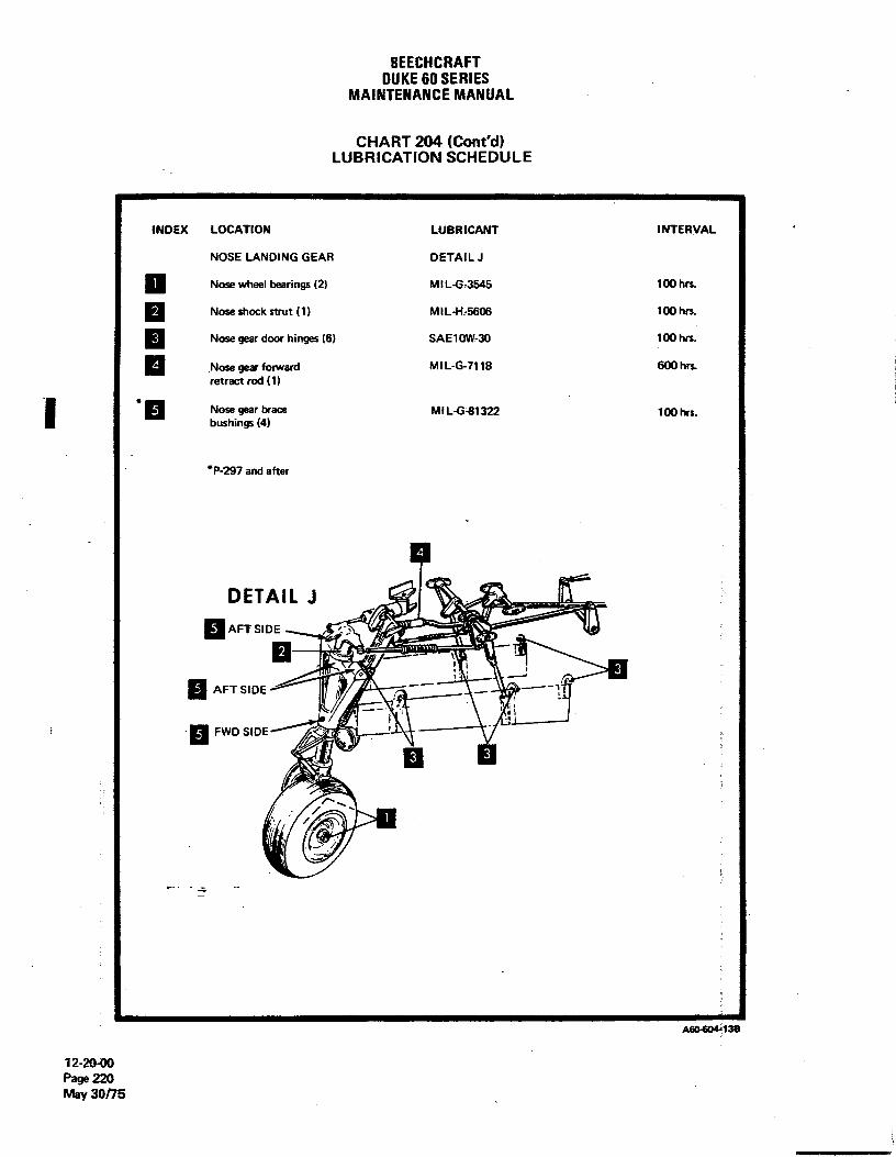
BEECHCRAFTDUKE60 SERIES
MAINTENANCEMANUAL
CHART 204 (Cont'd)LUBRICATION SCHEDULE
INDEX LOCATION LUBRICANT INTERVAL
NOSE LANDING GEAR DETAIL J
Nose wheel bearings (2) MIL-G-3545 100 hrs.
g Nose shock strut (1) MIL-H-5606 100 hrs.
g Nose gear door hinges (6) SAE10W-30 100 hrs.
Nose gear fonward MIL-G-7118 600 hrs.retract rod (1)
Nose gear brace MIL-G411322 100 hrs.- bushings (4)
*P-297 and after
DETAIL J
g AFT SIDE
AFTSIDE ..--
---¯¯lt
FWD SIDE
- -
12-204)0Page 220May 30/15

BEECHCRAFTDUKE60 SERIES
MAINTENANCEMANUAL
CHART 204 (Cont'd)LUBRICATION SCHEDULE
INDEX LOCATION LUBRICANT INTERVAL
CABLE PRESSURE SEALS DETAIL K
Control cable pressure seals (8) MIL-G-23827 1000 hrs.
g Trim tab cable pressure seals (3) MIL-G-23827 1000 hrs.
DETAIL K
A60 604-14A
12-2040Page 221Nov 2/73

untunonarsDUKE60SERIES
MAINTENANCEMANUAL
1 1 2 31 1
6 7
4
e o o¯]
25
10 11
12 13
15
10 1116
9
17
60131A
8 8 14
Fuselage Access Openings (Sheet 1 of 2)Figure 203
12-20-00Page 222Nov 2/73

BEECHCRAFTDUKE60 SERIES
MAINTENANCEMANUAL
1. Elevator Hinges 11. Uplock Cable, Retract Rods, Retract RodPressure Seals and Wing Stub Fuel Fittings
2. Tail Cone12. Lower Pedestal
3. Elevator Trim Tab Actuator13. Landing Gear, Gearbox and Actuator
4. Rudder Trim Tab Actuator14. Assist Step Mechanism
5. Deicer Dump Valve, Elevator Bell Crank,Rudder Bell Crank and Control Cables 15. Autopilot Aileron, Rudder and Elevator
Servos, Magnetic Navigation Sensing Element6. Vertical Stabilizer Deicer Hose (B-5P Autopilot) and Autopilot Computer
(H-14 Autopilot)7. Emergency Exit
16. Oxygen Filler and Bottle, Heater, Ram Air8. Wing Bolts Plenum, Brake Fluid Reservoir, Avionics
Equipment and Baggage Compartment9. Nose Cone
17. Cabin Door Hinges10. Intercooler
Fuselage Access Openings (Sheet 2 of 2)Figure 203
12-20-00Page 223Nov 2/73

BEECMCRAFTDUKE60 SERIES
MAINTENANCEMANUAL
28 8
31 12 10 11 9 8 7 6 2 1 1 29 6 5 2 9 18 12 31
32 5 4 3 26 17 4 3 32
LEFT WING (UPPER) RIGHT WING (UPPER)
12 14 18 27 4 25 25 2 27 21 18 18 14 1213
30 30
21 2318 19 20 22 2322 29 15 19
26
RIGHT WING (LOWER) LEFT WING (LOWER)6612-1A
Wing Access OpeningsFigure 204 (Sheet 1 of 2)
12-2%Page 224Oct 27/75

BEECHCRAFTDUKE60 SERIES
MAINTENANCEMANUAL
1. Leading Edge Fuel Cell Transmitter 15. Aileron Tab Actuator
2. Alternate Air and Fuel Pressure Solertoid 16. Leading Edge Fuel Cell
3. Nacelle Fuel Cell Transmitter and Plumbing 17. Nacelle Fuel Cell Plumbing
4. Nacelle Fuel Cell and Vent Line Plumbing 18. Box Section Fuel Cell
5. Fuel Vent Check Valve and Plumbing 19. Aileron Actuator and Pulley
6. Battery, Battery Relays, Voltage Regulators, 20. Aileron Cable, Fuel Vent and Battery VentOvervoltage Relays, Starter Relays, ParallelingRheostat, Fuel Flow inverter, Loadmeter Shunt, 21. Box Section Fuel CellFuse Block, Radio Inverter, Radio InverterCircuit Breaker and Relay, External Power 22. Fuel Vent Line and Alleron Tab CableDiode and Current Limiter for Battery
23. Fuel Vent Line7. External Power Receptacle
24. Landing Gear Attach Bolt8. Reverse Current Diode, External Power
and LH Control Relay 25. Fuel Boost Pump
9. Leading Edge Fuel Cell Transmitter and 26. Wing Attach BoltFuel Cell Installation
27. Cowl Flap10. Fuel Filler
28. Oil Level Indicator11. Remote Compass
29. Reverse Current Diode** 12. Landing Light
** 30. Remote Compass Detector* 13. Wing Tip Wiring and Fuel Vent Float Valve
14. Fuel Siphon Valve† 31. Fuel Filler
† 32. Wing Tip Access Openings
One rectangular opening on P-223 through P-347, P-349 through P-364P-223 through P-347, P-349 through P-364Optional P-348, P-365 and after
Wing Acess Openings (Sheet 2 of 2)Figure 204
12-20-00Page 225
Oct 27/75
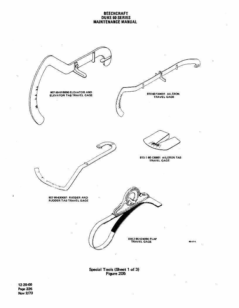
BEECHCRAFTDUKE60 SERIES
MAINTENANCEMANUAL
807 610Ø00 ELEVATOR ANDELEVATOR TAB TRAVEL GAGE 8104130001 AILERON
TRAVEL GAGE
810-1 130001 AILERON TABTRAVEL GAGE
807 60-630001 RUDDER ANDRUDDER TAB TRAVEL GAGE
81 9 E52 FLAP
Special Tools (Sheet 1 of 3)Figure 205
12-20-00Page 226Nov 2/73

BEECHCRAFTDUKE60 SERIES
MAINTENANCEMANUAL
50-590013TS1171-1TS1176-1TS1176-2TS1171-2
TS1222-4922 60-960000 PROPELLER TS1222-8 50-590014
TORQUE WRENCH ADAPTER
TS1176-10WING BOLT WRENCHES TS1171-10
TK1817 922-4 UPPER FORWARD WING BOLT WRENCH.
TS1171-2orTS1176-2 UPPER FOAWARD WING NUT TORQUE
WRENCH ADAPTER (for internal wrenchingnut).
TS1171-10 yorTS1176-10 UPPER FORWARD WING NUT TORQUE
WRENCH ADAPTER (for external wrenchingnut).
TK1817 922-5 LOWER FORWARD WING BOLT WRENCH. / TK1817 922-4
50-590014 LOWER FORWARD WING NUT TOROUE / TX1817 922-5
WRENCH ADAPTER.
TS1222-4orTS1222-8 UPPER AFT WING BOLT WRENCH.
TS1171-1OfTS1176-1or50-590013 UPPER AFT WING NUT TOROUE WRENCH
ADAPTER.
TK1817 922-4 LOWER AFT WING BOLT WRENCH.
TS1171-2-or -TS1176-2 LOWER AFT WING NUT TOROUE WRENCH
ADAPTER (for intemal wrenching nut).
.
TS117,1-10orTS1176-10 LOWER AFT WING NUT TOROUE WRENCH
ADAPTER (for extemat wrenching nut). so-o-7
Special Tools (Sheet 2 of 3)Figure 205
12-20-00Page 227
A14 Nov 30/83

BEECHCRAFTDUKE 60 SERIES
MAINTENANCEMANUAL
.: MODEL 400 SERVICE JACK
I
P/N 60-590013 (P-3 thru P41)P/N 60-590013-1 (P-62 and after)
101-590020-1FUEL SUMP DRAINWRENCH SERVICE JACK ADAPTER
SG17-8A.
Special Tools (Sheet 3 of 3)Figure 205
"END"
12-20-00Page 228Oct 27/75

BEECHCRAFTDUKE60 SERIES
MAINTENANCEMANUAL
CHAPTER 20
UST OF PAGE EFFECTIVITY
CHAPTERSECTIONSUBJECT PAGE DATE
20-EFFECTIVITY 1 Nov 30/83
20-CONTENTS 1 May 12/78
20-00-00 201 Apr 18/80202 Nov 30/83203 May 12/78204 May 12/78205 May 12/78206 May 12/78207 May 12/78208 May 12/78
"END"
20-EFFECTIVITY
Page 1A14 Nov 30/83

BEECHCRAFTDUKE60 SERIES
MAINTENANCEMANUAL
CHAPTER 20 - STANDARD PRACTICES - AIRFRAME
TABLEOF CONTENTS
CHAPTERSECTION
SUBJECT SUBJECT PAGE
STANDARD PRACTICES 20-00-00
Torque Wrenches 201Airplane Finish Care 202
Cleaning and Waxing Airplane Finish 202During Curing Period (90 days) 202After Curing Period 202
Exterior and Interior Finishes 202Exterior and interior Primers 202Enamel (Exterior Colors) 203Urethane (Exterior Colors) 203Lacquer (Interior Colors) 203Enamel (Interior Colors) 204
Painting Magnesium . 204Enamel Paint 204Urethane Paint 204
Special Paint Procedures 207
"END"
20-CONTENTSPage 1
May 12/78

BEECHCRAFTDUKE60 SERIES
MAINTENANCEMANUAL
STANDARD PRACTICES - AIRFRAME
TOROUE WRENCHES TOTA LENGTH
LWhen a torque wrench and adapter is used, (Figure 201)compensation must be made for the extra leverage gained.New indicator readings must be calculatedbefore the wrenchis used. To figure the desired lower readings which will actu-ally give the torques specified, use the following formula:
Original wrench length x specified torque = Desiredlengthof wrench + adapter reading
Example: D = Desired readingL = Length of torque wrenchA = Adapter length Torque Wrench and AdapterT = Torque Figure 201
D = ?L = 33 inches An acceptable method of checking the torque if a torqueA = 11 inches wrench is not available (Figure 202), is to attach a springT = 5,000 inch-pounds scale to a conventional flex or "T" handle inserted in an
adapter. Force should be applied in a direction= 165,000 = 3,750 inch-pounds perpendicular to an imaginary line extending from the center
33 + 11 7 of the bolt through the spring scale attaching point.
(LB)
90°
TOTAL LENGTH60-17-2
Computing Torque with Spring ScaleFigure 202
20-00-00Page 201Apr 18/80
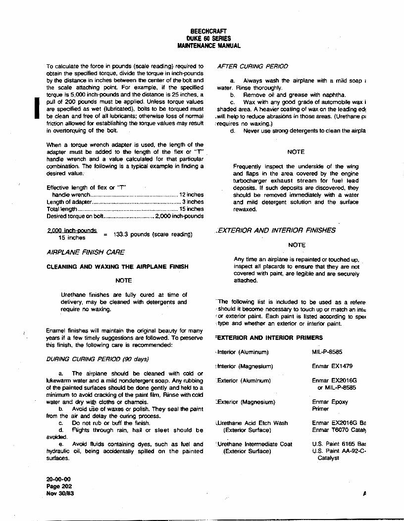
BEECHCRAFTDUKE60 SERIES
MAINTENANCEMANUAL
To calculate the force in pounds (scale reading) required to AFTER CURING PERIODobtain the specified torque, divide the torque in inch-poundsby the distance in inches between the center of the bolt and a. Always wash the airplane with a mild soap i
the scale attaching point. For example, if the specified water. Rinse thoroughly.torque is 5,000 inch-pounds and the distance is 25 inches, a b. Remove oil and grease with naphtha.
I pull of 200 pounds must be applied. Unless torque values c. Wax with any good grade of automobile wax iare specified as wet (lubricated), bolts to be torqued must shaded area. A heavier coating of wax on the leading ed!be clean and free of all lubricants; otherwise loss of normal .will help to reduce abrasions in those areas. (Urethane pifriction allowed for establishing the torque values may result riequires no waxing.)in overtorquing of the bolt. d. Never use strong detergents to clean the airpla
When a torque wrench adapter is used, the length of theadapter must be added to the tength of the flex or "T" NOTEhandle wrench and a value calculated for that particularcombination. The following is a typical example in finding a Frequently inspect the underside of the wingdesired value. and flaps in the area covered by the engine
turbocharger exhaust stream for fuel leadEffective length of flex or "T" deposits. If such deposits are discovered, they
handle wrench....................... .. .. ....................... 12 inches should be removed immediately with a waterLength of adapter............................ ........................ 3 inches and mild detergent solution and the surfaceTotal length ............................................................. 15 inches rewaxed.Desired torque on bolt...............................2,000 inch-pounds
2.000 inch-pounds .EXTERIOR AND INTERIOR FINISHES15 inches
= 133.3 pounds (scale reading)
NOTEAIRPLANE FINISH CARE
Any time an airplane is repainted or touched up,CLEANING AND WAXING THE AIRPLANE FINISH inspect all placards to ensure that they are not
covered with paint, are legible and are securelyNOTE attached.
Urethane finishes are fully cured at time ofdelivery, may be cleaned with detergents and The following list is included to be used as a refererequire no waxing. should it become necessary to touch up or match an inte
or exterior paint. Each paint is listed according to speltype and whether an exterior or interior paint.
Enamel finishes will maintain the original beauty for manyyears if a few timelysuggestions are followed. To preserve EXTERIOR AND INTERIOR PRIMERSthis finish, the following care is recommended:
laterior (Aluminum) MIL-P-8585DURINGCURINGPERIOD (90 days)
interior (Magnesium) Enmar EX1479a. The airplane should be cleaned with cold or
lukewarm water and a mild nondetergent soap. Any rubbing Txterior (Aluminum) Enmar EX2016Gof the painted surfaces should be done gently and held to a or MIL-P-8585minimum to avoidcracking of the paint film, Rinse with coldwater and dry with cloths or chamois. Ixterior (Magnesium) Enmar Epoxy
b. Avoid uše of waxes or polish. They seal the paint Primerfrom the air and delay the curing process.
c. Do not rub or buff the finish. ilJtethane Acid Etch Wash Enmar EX2016G Bed. Flights through rain, hail or sleet should be (Exterior Surface) Enmar T6070 Catal3
avoided.e. Avoid fluids containing dyes, such as fuel and IJrethane intermediate Coat U.S. Paint 6165 Ba:
hydraulic oil, being accidentally spilled on the painted (Exterior Surface) U.S. Paint AA-92-C-surfaces. Catalyst
20-00-00Page 202Nov 30/83 A

BEECHCRAFTDUKES)SERIFJi
MAINTENANCEMANUAL
ENÀMEL Huntsman Red 118684-315Toreador Red 118684-316
(Exterior Colors) Chianti Red 118684-317Matterhorn White 118684-318
Pacific Blue 118684-1 Black 118684-319
Morning Glory Blue 118684-3 Sable Brown 118684-320
Blueberry Blue 118684-5 Capri Blue 118684-322Surf Green 118684-7 Champagne Gold 118684-323Shamrock Green 118684-9 Omaha Orange 118684-324Turquoise 118684-11 Kingston Gray 118684-325San Mateo Wheat 118684-13 MarlinBlue 118684-393Lemon Yellow 118684-15 Bahama Blue 118684-395Saturn Gold 118684-17 Pavonne Blue 118684-397CastleTan 118684-19 MatadorFkad 118684-399BeaverBrown . 118684-21 SunburstYellow 118684-031Flaniingo 118684-23 JadeWiistGreen 118684-403Huntsman Red 118684-25 Astro Blue 118684-405Toreador Red 118684-27 Peacock Turquoise 118684-407Chianti Red 118684-29 Terrace Blue 118684-409Matterhorn White 118684-31 Sahara Tan 118684-411Black 118684-33 Prairie Beige 118684-413Champagne Gold 118684-39 Antique Gold 118684-415Jubilee Gold 118684-221 Beechwood 118684-419Sable Brown 118684-223 Embassy Red 118684-421Sunshine Yellow 118684-231CapriBlue 118684-265 LACOULTROmaha Orange 118684-273Kingston Gray 118684-299 (Interior Colors)Peacock Turquoise 118684-333
Terrace Blue 118684-335 AJpineBlue 118684-63SaharaTan 118684-337 Anchor Gray 118684-75
Prairie Beige 118684-339 DullBlack 118684-133Antique Gold 118684-341 Autumn Smoke 118684-155Beachwood 1186&‡-345 DesedBeige 118684-181Embassy Red 118684-347 Driftwood 118684-183Marlin Blue 118684-349 Artic Beige 118684-235
Bahama Blue 118684-351 Sandusky (Gold) 118684-237Pavonne Blue 118684-353 Frontier (Gold) 118684-239Matador Red 118684-355 BanffBlue 118684-241Sunburst Yellow 118684-357 Sable Brown 118684-257JadeMistGireen 118684-359 Turquoise 118684-275Astro Blue 118684-361 Mist Green 118684-277
Pumpkin 118684-279
047E77447/E Broadvvay Blue 118684-283
SunBeitge 118684-285(Exterior Golors) Torch Red 118684-329
Spanish Gold 118684-423Jubilee Gold 118684-302 Canyon Blue 118684-427
Morning Glory Blue 118684-304 GulfBlue 118684-429Blueberry Blue 118684-305 Maize Gold 118684-455SudGreen 118684-306 SilverGray 118684-457Shamrock Green 118684-307 Green 118684-461Turquoise 118684-308 EksvBlue 118684-471
LernonYellow 118684-310 NewBronze 118684-475
CastleTan 1186&4-312 VamityBlue 11969e‡-477
20-0(M)OPage 203
tiay 12/78

BEECHCRAFTDUKE60 SERIES
MAINTENANCEMANUAL
ENAMEL c. Proceed to prime with a wet coat of MIL-P-8585zinc chromate pdmer (26, Chart 207, 91-00-00) thinned one
(Interior Colors),
part primer and two parts toluol. A heavy hiding coat of thisprimer is not desired and will impair performance.
Insignia Red 94-509 d. The exterior surfaces are now ready for color coat.Black 94-515 e. Spray on twothin topcoats of enamel.Instrument Black Color No. 514 per
ANA Bulletin EXTERIOR PAINT TOUCH-UP REPA/R (ENAMEL)No. 157
a. Mask around the skin containing the damagedShort cut masking jobs for your paint department are possi- area.ble when you use pre-cut paint patterns and numbers. Stripe b. Remove any loose edges of paint by using a highand numeral pattems are available from Mid-America Mark- tack adhesive tape around the edge of the damaged area.ing inc., 1720 S. 151 W., Wichita, Kansas 67052, or any c. Using a coarse sandpaper, fair the edge of theother equivalent product may be used. Current listings in- damaged area with the metal.clude 4, 12, and 20 inch Call Numbers and Letters. Time can d. When the edge of the paint begins to "feather" intobe saved when using these pattems and a much neater final a smooth joint,use a fine grade ofsandpaper to eliminate thepaint job can be expected. sand scratches left by the coarse paper so that the finish will
be perfectly smooth. Take care to avoid removing any morePA/NT/NG ALUM/NUM metal then is absolutely necessary.
e. Wash the sanded area with a solvent, such asENAMEL PAINT naphtha or toluol. Change the wash cloths used _for this
purpose frequently so that all the sanding dust willbe pickedPREPARATION OF AIRPLANE ALUMINUM EXTERIOR up.FOR PA/NT f. After the area to be touched up has been cleaned
with solvent until all trace of discoloration is gone, applya thina. Mask windows with a double thickness of paper. coat of pretreatment primer to the damaged area.
Cover all openings where paint might enter airplane. g. Spray two or three coats of the zinc chromateb. Sand scratches and rough areas to improve primer for a heavier than normal build-up.
smoothness. h. After the primer has dried, sand the area beingc. Clean surface of airplane with solvent, (lacquer repaired with a medium fine sandpaper. Sand the edge ofthe
thinner or methyl ethyl ketone), to remove shop primer, ex- repair area until the indentation where the metal and the oldposed sealer, and other shop soils. paint meet is gone. Ifit is necessary, apply additional primer
d. Lightly roughen all scratches with nylon pad to until the junction of the paint and metal is no longer visible.insure a satisfactory paint base. i. Spray on twothin topcoats of finish paint.
e. Reclean the roughened surface with solvents toensure removal of all hand prints and dirt. URETHANE PAINT
APPLICA T/ON OF EXTERIOR PAINT ON ALUMINUM The need for an extremely hard finish for protection againstSKINS sandblast during takeoffand landings led to the development
of urethane coatings for airplanes. Urethane paint dries into aa. Prime surfaces with wash primer (25, Chart 207, high gloss and retains color much better than standard fin-
91-00-00). Mix only enough primer for use within an eight ishes. It is unaffected by the chemicals in hydraulic fluids,hour priod. Primer mixed longer than eight hours must be deicer fluids and fuels and requires less care and mainte-discarded. nance than other finishes.
b. Apply one coat of wash primer. Keep air pressureat a minimum to prevent overspray. URETHANE PAINT REPAIR PROCEDURES
NOTE NOTE
Temperature and humidity willeffect drying time The_time normally required for urethane paint toof the primer. It should dry at least 15 minutes cure must be extended at temperatures belowbefore recoating the surface (test surface with 70°F. The paint will not cure at temperatureslight fingernail pressure). below 60°F.
2ooo-ooPage 204May 12/78

BEECHCRAFTDUKE60 SERIES
MAINTENANCEMANUAL
Dukes painted with urethane paints are finished with pre- PRETREATMENT (WASH) PRIMER FOR URETHANEtreatment'(wash) primer, urethane primer and a topcoat of PAINTurethane enamel. The following procedures include cleaning,paint stripping, repaint preparation, priming, applying a An acid etching primer that conforms to MIL-C-8514 shouldurethane topcoat and an altemate method for small repairs be applied to improve adhesion of the finishing coats.not requiring paint stripping. Careful observation of these EX2016Gbase and T6070 catalyst (products of Enmar Paintprocedures should result in a smooth, hard, glossy finish with Company, Wichita, Kansas) are used in equal parts as afirm adhesion for maximum life. pretreatment wash primer at the factory.
a. Mix the primer in accordance with the manufactur-STRIPPING AND CLEANING URETHANE PAINT ers instructions.
b. Apply a thin coat of primer. It should be permittedBecause of their resistance to chemicals and solvents, to dry for at least an hour, but not over six hours, before theurethane paints and primers require a special paint stripper. next coat of urethane paint is applied.If a urethane stripper is not available, a good enamel strippermay be used. Removing the finish with such a substitute will URETHANE PR/MERrequire several applications while working the stripper in witha stiff brush or wooden scraper. a. Mix two parts of the 6165 primer base to one part
AA-92-C-4A catalyst (products of U.S. Paint Company,a. Mask around the edge of the skin or skins contain- Wichita, Kansas) for intermediate primer.
ing the damaged area. Use a double thickness of heavypaper to prevent accidental splashes of paint stripper frompenetrating the masking. NOTE
b. Apply urethane stripper as indicated by the manu-facturer's direction. Try to stay approximately 1/8 inch away For the best results, these directions must befrom the masking tape. This will necessitate a little more followed carefully; for some manufacturers re-cleanup upon finishing, but will prevent damage to the finish quire that the primer be allowed to set for 1/2on the next skin. The stripper will not attack aluminum during hour after the catalyst and base have been mix-the stripping process and can be neutralized afterwards by ed while others recommend immediate use afterrinsing the affected area with water. mixing.
b. Apply a coat of urethane primer with a spray gunCAUTION using 35 to 40 psi of air pressure. A dappled appearance
indicates that the coat is thin.Urethane strippers usually contain acids that irri- c. The primer should be permitted to dry approxi-tate or burn the skin. Wear rubber gloves and mately two hours at a temperature of 85° to 90°F at loweye protection when using the stripper. humidity. When the primer can not be scratched with a finger-
nail or will not ballup with sandpapering it is ready for thetopcoat application.
d. If the initial primer coat is allowed to cure for morethan 24 hours before the topcoat is applied, sand the primer
c. Rinse the area with water and dry. coat slightly to roughen the surface and ensure adhesion.d. Wash the stripped area carefully with a solvent Wipe off the sanding dust with a cloth dampened with a
such as methyl ethyl ketone or lacquer thinner. This will solvent (such as lacquer thinner), then apply the topcoat.preverit ting particles of loose paint from adhering to thestripped area. URETHANE TOPCOAT APPLICATION
e. Using a nylon scratch pad or aluminum wool dip-ped in water, clean the surface with a cleanser such as Bon a. Mixthe paint and catalyst as directed by the manu-Ami, Ajax, Comet cleaner, etc. A good scouring will leave the facturer.surface completely clean. b. Apply the topcoat with a spray gun at 35 to 45 psi
f. Thoroughly rinse with clean water and carefully dry of air pressure. Two coats are normally required to fullythe affected area. If the stripped area includes several joints conceal the primer and build up the topcoat filmfor adequateor skin laps, let the airplane sit until all moisture has dried. service life and beauty. The urethane finish will normally cureThis may be accelerated by blowing the skin laps and seams to 85% of its full hardness in 24 hours at temperatures ofwith compressed air. Wet masking should be replaced.
80°F or higher.
20410410Page 205
May 12/78

BEECHCRAFTDUKE60 SERIES
MAINTENANCEMANUAL
URETHANE TOUCH-UP REPA/R CAUT/ON
a. Mask around the skin containing the damaged Strippingshouldbeaccomplishedinawellventi-area. lated area since prolonjed exposure to high con-
b. Remove all loose edges of paint by using a high centrates of vapor may irritate the eyes andtack adhesive tape around the edge of the damaged area. lungs.
c. Using a coarse sandpaper, fair the edge of thedamaged area.
d. When the edge of the paint begins to fair into a o. Allow the paint stripper to work for 20 to 30smooth joint, use a fine grade of sandpaper to eliminate the minutes, then work the remaining paint loose with a bristlescratches left by the coarse paper. Take care to avoid remov. brush,ing any more metal than is absolutely necessary.
e. Wash the sanded area with a solvent, such aslacquer thinner or toluene. (Do not use methyl ethyl ketone CAUTIONas it will soften urethane paint.) Change the wash cloths usedfor this purpose often so that all the sanding dirt will be picked Never use a wire brush for it will damage theup. magnesium surface.
f. After the area to be touched up has been cleanedwith solvent until all traces of discoloration are gone, apply athin coat of pretreatment primer to the damaged area. d. Remove the masking paper and wash the affected
arearthoroughlywith water under high pressure. Remove allretaanents of paint with lacquer thinner.
NOTE se. Sand the repaired area lightly, then apply Dow No.
If a metal conversion coating such as iridite or194o aid in the prevention of corrosion.
alodine is used, the wash primer coating can be PAINTING MAGNESIUM SURFACESdispensed with. If the metal has not been treatedwith a metal conversion coating and no wash ra. Prepare the surface to be repainted as indicatedprimer is available, carefullyclean the surface to under PAINT REMOVALFROM MAGNESIUM SURFACES.be touched up and apply urethane primer to the Clean the affectedarea thoroughlywith lacquer thinner or anbare metal. This should produce a satisfactory eguivalent solvent.undercoat for the repair area.
NOTE
g. After the urethane primer has cured for 24 hours, Unprimed areas of magnesium castings are tosand the area under repair with medium fine sandpaper. be coated with MIL-C-16173 corrosionpreventa-Sand the edge of the repair area until the indenta on.where tive compound (43, Chart 207, 91-00-00) unlessthe metal and old paint meet is gone. If necessary, apply these areas will come into contact with oil oradditional urethane primer until the juncture of old paint and grease afterassembly. Any holes in the castingsmetal is no longer visible. which will receive bushings or bearings shall be
h. Spray on two topcoats. coated with wet unreduced zinc chromate primeror corrosive preventative compound at the timeof installation.
PAINTING MAGNES/UM b. Prime the affected area and apply either theenamel or urethane topcoat if applicable.
PAINT REMOVAL FROM MAGNESIUM SURFACES
a. Mask around the edge of the damaged area with a NOTEdouble thickness of heavy paper to prevent accidentalsplashes of paint stripper from penetrating the masking. Do not apply wash primer to magnesium sur-
b. Apply paint stripper (42, Chart 207, 91-00-00) to faces. Allowa minimum of four hours drying timethe skin under repair with a brush or non-atomizing gun. between applicationof the primer and top coat.
2ooo-ooPage 206May 12/78

BEECHCRAFTDUKE60SERIES
MAINTENANCEMANUAL
SPECIAL PAINT PROCEDURES Apply a thin coat of Dow Corning No. 7 after the finish topcoat is dry.
PROPELLER BLADESENCLOSED AREAS SUBJECT TO HIGH HUMIDITY
Paint the backs of the propeller blades with quick dryingenamel per MIL-E-5556, color No. 37038 per Federal Stan- Steel, aluminum or magnesium parts and assemblies whichdard 595. are enclosed and subject to high humidity should be pro-
tected against corrosion by coating with either epoxy primer,LANDING LIGHTS MIL-C-16173 corrosion preventative compound, light grease
or heavy oil.Paint the landing light wells, excluding the ribs at the inboardand outboard ends, the spar arid attaching angles, withquick LOWER WING AND FLAP SKINSdrying enamel per MIL-E-5556, color No. 37038 per FederalStandard 595.. If inspection of the lower wing and flap area aft of the exhaust
stacks disclose corrosion from fuel lead deposits, removeAIR CONDITIONER EVAPORATOR COMPARTMENT with a mild soap and water solution. Use a stainless steel
wire brush to remove deeper, more resistive corrosion. IfApply epoxy primer (24, Chart 207, 91-00-00) to the entire corrosion is so deep that 15% or more of the skin thickness issurface area of the parts which make up the compartment. removed, the surface should be replaced. If skin thickness
has been reduced by less than 15% (after the corrosion hasbeen removed), the area should be treated with cleaner (41,
NOSE RADOME Chart 207, 91-00-00) or an equivalent corrosion removingcompound conforming to MIL-C-38334. The skin should be
Sanding surfacer or filler may be used to obtain a smooth treated both externally and (where accessible) intemally andsurface. Sand with 180 sandpaper just enough to remove the given a protective coating as described below, then primedglaze. After sanding, the radome contour shall be free of pits, and painted. Inspection door nut plates should be removedholes or irregularities which may reduce radar transmissivity prior to treating the skins with corrosion removing compound.and range. If glass laminate fibers are exposed, a hot resin If corroded, the nut plates should be replaced.wipe should be applied to seal the Iaminate and followed witha light sanding with No. 400 sandpaper to remove the glaze.Do not repair with Devcon, body putty or any other plastics CAUT/ONwhich have a different expansion coefficient than the originalresin. Apply three thin cross-coats of white elastromeric The corrosion removing compound should bepolyurethane (product of Hughson Chemical Co. Erie, Penn.) applied in accordance with the manufacturersconsisting of CD 857-40A (two parts by volume) and CD instructions and cautions.857-408 (one part by volume) to the forward 15 to 17 inchesof the nose cone. The accelerator and base are available inthe kit form (P/N CD857-40 1-1/2 pint) through the in addition to the above noted treated skins, new flaps andBEECHCRAFT Dealer Organization. Allow one hour drying new skin splices should be treated externally with a protec-time between coats and 48 hours drying time before applica- tive coating, as described below, primed and painted, and alltion of urethane topcoat. accessible interior aluminum wing parts on the lower side of
the wing, between wing stations 66.00 and 108.281 and aft ofSURFACES SUSCEPTIBLE TO MUD AND SPRAY the second stringer att of the front wingspar, should be given
a protective coating, as described, and then primed with zincAppigone coat of white epoxy paint to the following areas: chromate.
1. Main and nose landing gear wheel wells, a. MixAlodine 1200 or 1200S (a product of Amchem2. Interior surface of landing gear doors. Products, Inc., Ambler, Pennsylvania) with water in a ratio of
,3. Main and nose landing gear assemblies. 3 to 4 ounces per gallon of water.
b. Place in a plastic container and allow to dissolve atRUBBER SEALS least one hour.
c. Add 10 milliliters nitric acid per gallon of solution.Apply one coat of a thoroughlydissolved solution of one part d. Prepare the surface by wiping with Stoddard Sol-Oakite No. 6 and two parts water to all rubber sudaces that vent or methyl ethyl ketone, then scrubbing with a nylonare to come into contact with metal or other rubber surfaces. abrasive pad to remove oxide films. Rinse with water and
2(M)O-00Page 207
May 12/78
BEECHCRAFTDUKE60 SERIES
MAINTENANCEMANUAL
repeat the above procedure until water will not bead on the than a heavier coating is preferable for a paint base, espe-surface. cially for epoxy primers. Streaks from brushing, or rundown
e. After cleaning, immediately treat the sudace, using of excess solution are allowable, as are slight chromic acida cheesecloth pad, cellulose sponge, or nylon brush to apply stains.the solution with light pressure and continuous, even motion. f. Remove excess solutionwith coldrunning water orOn curved or inclined surfaces, begin application at thelower a cheesecloth pad wetted with clean water. Never use a highedge of the work to minimize streaking. Keep the surface wet pressure hose rinse, since the freshly formed chemical filmwith the solutionfor 1 to 3 minutes so that acontinuous film is will be removed or damaged. Alltreated parts should be keptobtained, with neither a grayish appearance nor a dark, pow- clean before priming and painting, which should follow thedery, non-adherent coating. Generally, a light coating, rather chemical film application as soon as practical.
"END"
2040.00Page 208May 12/78

BEECHCRAFTDUKE60 SERIES
MAINTENANCEMANUAL
CHAPTER 21
LIST OF PAGE EFFECTIVITY
CHAPTERSECTIONSUBJECT PAGE DATE
21-EFFECTIVITY 1 Feb 22/802 Feb 22/80
21-CONTENTS 1 May 30/752 Feb 22/803 Feb 22/80
21-00-00 1 May 30/752 May 30/75
101 May 30/75102 May 30/75103 May 30/75104 _ May 30/75105 May 30/75106 May 30/75107 May 30/75108 May 30/75109 May 30/75110 May 30/75111 May 30/75
21-10-00 1 Nov 2/73201 Nov 2/73
21-20-00 201 Nov 2/73202 May 30/75203 May 30/75
21-30-00 1 May 30/752 May 30/753 May 30/754 May 30/755 May 30/756 May 30/757 May 30/75
201 May 30/75202 May 30/75203 May 30/75204 Feb 22/80205 Feb 22/80206 Feb 22/80207 Feb 22/80208 Feb 22/80209 Feb 22/80210 Feb 22/80211 Feb 22/80
21-EFFECTIVITYPage 1
Feb 22/80

BEECHCRAFTDUKE60SERIES
tiAINTENANCEKANUAL
CHAPTER 21
L/ST OF PAGE EFFECTIVITY (Cont'd)
CHAPTERSECTIONSUBJECT PAGE DATE
21-HNDO 1 Nov2DK!2 May 30/75
201 Nov 2/73202 Nov 2/73203 Nov2/X3204 Nov2DRI205 Nov2AK3
21-50-CK) 1 May30/75201 Nov2ft3202 Nov2/73203 Nov 2/73204 Nov 2ft3205 Nov2ft3
"END"
21-EFFECTIVITYPage 2Feb 22/80

BEECHCRAFTDUKE60 SERIES
MAINTENANCEMANUAL
CHAPTER 21 - AIR CONDITIONING
TABLE OF CONTENTS
CHAPTERSECTION
SUBJECT SUBJECT PAGE
GENERAL 21-00-00 1Description and Operation 1
Pressurization System 1Air Conditioning System 1Heater System 2
Troubleshooting 101Pressurization System 101Heater System 107Air Conditioning System 109
COMPRESSION 21-10-00 1Description and Operation 1Maintenance Practices - 201
Intercooler Removal 201Intercooler Installation 201Intercooler Control Rigging 201Firewall Shut-Off Valve 201
DISTRIBUTION 21-20-00 201Maintenance Practices 201
100-Hour Inspection 201
PRESSURIZATION CONTROL 21-30-00 1Description and Operation(P-3 thru P-307) 1
Pressurization System Operational Characteristics 1Cabin Altitude Controller (Manual) 3Cabin Altitude Controller (Motorized) . 3Differential Control Valve and Safety Valve 4Pressurization Test Switch 4
Description Operation (P-308 and after) 5Maintenance Practices (P-3 thru P-307) 201
Cabin Altitude Controller Filter (Motorized) 201Differential Control Valve and Safety Valve Removal 201Differential Control Valve and Safety Valve Installation 201Differential Control Valve and Safety Valve Adjustment 201Pressurization System Adjustment Procedures 201Cabin Altitude Controller Removal (Manual) 202
abin Altitude Controller Installation (Manual) 202Cabin Altitude Controller Adjustment (Manual) 202Cabin Altitude Controller Removal (Motorized) 203Cabin Altitude Controller Installation (Motorized) 203Cabin Altitude Controller Adjustment (Motorized) 203Pressurization Test Procedure 203
21-CONTENTSPage 1
May 30/75

BEECHCRAFTDUKE60 SERIES
MAINTENANCEMANUAL
CHAPTER 21 - AIR CONDITIONING
TABLE OF CONTENTS (Cont'd)
CHAPTERSECT10N
SUBJECT SUBJECT PAGE
PRESSURIZATION CONTROL (Cont'd)Maintenance Practices (P-308 and after) 21-30-00 204
Outflow Vafve and Safety Valve Aemoval 204Outflow Valve and Safety Valve Installation 204Outflow Valve and Safety Valve Adjustment 204Outflow and Safety Valve Cleaning 204Safety Valve Filter and Orifice Cleaning 205Functional Test of Outflow and Safety Valve (P-308 and after) 205
Outflow Valve Flight Check 205Safety Valve Ground Check 205
Cabin Altitude Controller Removal 205Cabin Altitude Controller Installation 205Cabin Pressurization ControllerAdjustment 206Cabin Altitude Controller Filter and Orifice Cleaning 206Auxiliary Volume Tank Removal 206Auxiliary Volume Tank instaffation 206Pressurization Test Procedure (P-308 and after) 206Cabin Pressurization Leakage Test (P-4 and after) 207Test Equipment (P-4 and after) 207Test Procedure (P-4 and after) 208
HEATING 21-40-00Description and Operation i
Heater Control System 1Heater Operation 1
Maintenance Practices 201Heater Removal 201Heater Installation 201Combustion Air Blower Removal 201Combustion Air Blower Installation 201Heater Ignition 202Vibrator Aemoval 202Vibrator installation 202Inspection and Servicing (Spark Plug) 202Temperature Sensors and Control
Rheostat Test 203Fuel Pump 205
COOLING - -21-50-00 1
Description and Opëration 1Refrigerative Air Cooling System 1
Maintenance Practices 201Charging the Air Conditioning System 201Air Conditioning Functional Test 201Checking Compressor Oil Level 201Evaporator Air Fifter Replacement 203Rigging the Air Scoop 203Condenser Blower Removal 204
21-CONTENTSPage 2Feb 22/80

BEECHCRAFTDUKE60 SERIES
MAINTENANCEMANUAL
CHAPTER 21- AIR CONDITIONING
TABLE OF CONTENTS (Cont'd)
CHAPTERSECTION
SUBJECT SUBJECT PAGE
COOLING (Cont'd) 21-50-00Maintenance Practices (Cont'd) 201
Condenser Blower Installation (Cont'd) 204Compressor Belt Tension Adjustment 204Compressor Belt Removal 204Compressor Belt Installation 204Compressor Removal 204Compressor installation 205
"END"
21-CONTENTSPage 3
Feb 22/80

BEECHCRAFTDUKE60 SERIES
MAINTENANCEMANUAL
GENERAL - DESCRIPTION AND OPERATION valves on the rear pressure bulkhead. When placed in theMANUAL COOL HI position, the switch bypasses theautomatic controls and allows maximum air conditioningoutput. The maximum output is limited by an evaporator
PRESSURIZA T/ON SYSTEM thermal switch and an overpressure switch. The MANUALCOOL LO position allows a hot-gas bypass valve (if
Pressurized air for the cabin is taken downstream from the installed) to be cycled on and off by a timer. The bypassturbocharger compressor of each engine and reduced to a valve regulates the flow of the refrigerant to the condenserusable flow by a sonic nozzle (or venturi). When sonic allowing partial cooling of the cabin.velocity is reached by the air flowing through the throat ofthe nozzle, each engine is producing the maximum flow On serials P-123, P-127 and after, and prior airplanes whichrate of 4 to 5 pounds per minute. Total air flow from both have complied with Service Instructions 0320426 aengines will deliver approximately 8 to 10 pounds per MANUAL COOL position replaces the MANUAL COOL Hlminute and maintain a cabin pressure differential of 4.6 psi. and LO positions on the mode selector switch. Two
BLOWER positions are placed on the mode switch to allowThe air then passes through a firewall shutoff valve, through the blower to be selected without cycling through thean intercooler and into the cabin beneath the pilot and opposite mode.copilot floorboards. The intercooler reduces the heatacquired by the air during pressurization with a flow of ram The air scoop and ramp assembly located in the upper RHair from a scoop at the leading edge of each wing root. nacelle controls the air circulation through the condenserWithin the cabin pressure vessel a check valve is installed at compartment and is completely automatic. The air scoopeach pressurization outlet. In the event of an engine failure and ramp assembly has three positions; "closed" (when theat altitude the check valve will close on the dead engine air conditioning is not in use), "flight" (air scoop extendedside, preventing a loss of cabin pressurization. about 2 inches above the nacelle), and "ground" (air scoop
fully extended). When the air conditioning is turned on, aLocated on the forward side of the aft pressure bulkhead switch incorporated on the landing gear selects air scoop(P-3 through P-246) and on the aft side of the aft pressure position; gear down, the air scoop will open to thebuikhead (P-247 and after) are two valves; the differential "ground" position; gear off the ground, the air scoop willcontrol valve and the safety/dump valve. A pressurization open or lower to the "flight" position. The condenser fan,controller on the right subpanel pneumatically regulates the which is wired in circuit with the landing gear uplockdifferential control valve to maintain the selected cabin switch, operates only when the air conditioning mode isaltitude. selected and the airplane is on the ground.
The air conditioning system is similar to many home andA/R CONDITIONING SYSTEM automotive units and consists of six major components.
The belt-driven compressor, which is coupled by a magneticThe optional air conditioning system is a recirculating air clutch, compresses the refrigerant to a high pressure, highcooling system containing a 16,000 BTU refrigerative type temperature gas. This gas passes through the condensercooler. The unit is controlled by an automatic temperature where cooling air removes heat from the gas, condensing itcontrol and three sensing elements. to a liquid state. The liquid is then passed through the
receiver-dryer where any moisture or foreign material isA six position mode switch controls the heater and air removed from the system. The refrigerant flows to theconditioner system; however, each system operates expansion valve where it is metered into the evaporator at aindependently of the other. When placed in AUTO rate which allows all the liquid to return to a gas. The heatposition, the temperature is automatically controlled required for evaporation is absorbed from the cabin airthrough thitemperature controller located on the forward passing over the evaporator coils. After passing through thepressure bulkhead above the pilot pedals. It also regulates evaporator, the refrigerant returns to the compressor at athe cabin temperature variations monitored at the sensing reduced pressure. For partial cooling, a hot gas bypass valveunits. The sensing units are located in the ram air inlet, allows a portion of the gas to bleed off from the condenser,heater outlet duct and forward of the two pressure control cycling back through the compressor.
21-00-00Page 1
May 30/75

BEECHCHAFTDUKE60 SERIES
MAINTENANCEMANUAL
NOTE NOTE
Beginning with airplane serials P-123, P-127 and The low pressure switch which was originallyafter, and prior airplanes having installed Kit installed on airplane serials P-275 throughNumber 60-5006, the hot gas bypass valve, line P-292 and P-294, prior to complianœ with ·
and suction accumulator were removed from Service instructions 0599-427, actuated at athe system. pressure of 18 ± 2 psi.
An overpressure switch and a pressure relief valve areincorporated into the system to regulate system(compressor discharge) pressure. The overpressure switch islocated in the condenser compartment of the right nacelleand is set to actuate at 375 ± 10 psi. When this switch is HEATER SYSTEMactuated, power is removed from the compressor magneticclutch and the 3 amp fuse is shorted through a resistor tothe airplane structure. The fuse is thus opened, preventing The heater system consists of a 45,000 BTU combustion airfurther operation of the compressor magnetic clutch and heater, (located under the nose baggage compartmentthe compressor until the system has been serviced. A floor), a six position mode switch, vent air blower,pressure relief valve, located on the compressor discharge combustion air blower, heater fuel pump, five outlets, anline immediately before it enters the condenser, is set to automatic temperature control and three sensing elements.bleed off pressure at 450 psi.
In flight, when pressurized, the vent blower obtains airOn airplane serials, P-275 and after, and on those prior through the cabin air check valve, forces it through theairplanes which are in compliance with the Serviœ heater and to the cabin outlets. Inthe unpressurized mode,Instructions 0599-427, a low pressure switch is installed on in flight and for ground operations, the vent blower obtainsthe evaporator. This switch is designed to actuate when the air from the cabin and the ram air plenum chamber andrefrigerant pressure drops to 7 ± 1 psi. The actuation of the forces it through the heater and to the cabin outlets.Iow pressure switch shorts the 3 ampere fuse to airplanestructure through the resistor located near the evaporator. On serials P-3 through P-126, except P-123, a vent airThe fuse, located in the right nacelle, is thus opened, distribution bypass valve, located on the forward pressurepreventing further operation of the compressor magnetic bulkhead, allows air to be directed into the pilot'sclutch and the compressor until the air conditioner system compartment area and is regulated by a control knob onhas been serviced. the pilot's left subpanel.
"END"
21-00-00Page 2May 30/75
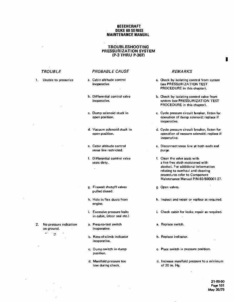
BEECHCRAFTDUKE60 SERIES
MAINTENANCEMANUAL
TROUBLESHOOTINGPRESSURIZATION SYSTEM
(P-3 THRU P-307)i
TROUBLE PROBABLE CAUSE REMARKS
1. Unable to pressurize a. Cabin altitude control a. Check by isolating control from systeminoperative. (see PRESSURIZATION TEST
PROCEDURE in this chapter).
b. Differential control valve b. Check by isolating control valve frominoperative. system (see PRESSURIZATION TEST
PROCEDURE in this chapter).
c. Dump solenoid stuck in c. Cycle pressure circuit breaker, listen foropen position. operation of dump solenoid; replace if
inoperative.
d. Vacuum solenoid stuck in d. Cycle pressure circuit breaker, listen foropen position. operation of vacuum solenoid; replace if
inoperative.
e. Cabin altitude control e. Disconnect sense line at both ends andsense line restricted. purge.
f. Differential control valve f. Clean the valve seats withseats dirty. a lint-free cloth moistened with
alcohol. For additional informationrelating to overhaul and cleaningprocedures refer to ComponentMaintenance Manual PIN 60-590001-27.
g. Firewall shutoff valves g. Open valves.pulled closed.
h. Hole in flex ducts from h. Inspect and repair or replace as required.engine.
i. Excessive pressure leaks i. Check cabin for leaks; repair as required.in cabin, (door seal etc.)
2. No pressure indication a. Press-to-test switch a. Replace switch.on ground. inoperative.
¯b. Rate-of-climb indicator b. Replace indicator.
inoperative.
c. Dump switch in dump c. Place switch in pressure position.position.
d. Manifold pressure too d. Increase manifold pressure to a minimumlow during check. of 20 in. Hg.
21-00-00Page 101
May 30/15

BEECHCRAFTDUKE60 SERIES
MAINTENANCEMANUAL
TROUBLESHOOTINGPRESSURIZATION SYSTEM (Cont'd)
(P-3 THRU P-307)
TROUBLE PROBABLE CAUSE REMARKS
3. Maximum cabin differ- a. Differential control valve a. Clean valve as described in the Componentential pressure exceeds inoperative. Maintenance Manual, P/N 6Œ590001-27,4.6 psi. or replace valve.
b. Cabin altitude and dif- b. Replace indicator.ferential pressure in-dicator inoperative.
c. Ambient air sense line c. Inspect lines and fittings; tighten orbetween safety and replace as required.differential control valveleaking.
4. Maximum cabin differ- a. Safety valve and a. Clean valve as described in theential pressure exceeds differential control Component Maintenance Manual, P/N4.9 psi. valve inoperative. 60-590001-27, or replace valve.
b. Ambient air sense line b. Inspect lines and fittings; tighten orbetween safety and differential replace as required.control valve ruptured,loose fittings.
5. Cabin pressure slow to a. Cabin altitude control sense a. Inspect and repair or replace as required.respond to change in line kinked or restricted.selected cabin altitude.
b. Cabin altitude control b. Replace filter.filter clogged.
6. Cabin altitude higher a. Cabin altittide controller a. Adjust controller.than selected altitude. out of adjustment.
b. Cabin altitude indicator b. Replace indicator.inoperative.
c. Cabin altitude control c. Inspect and repair or replace as required.sense line kinked orrestricted.
d. Cabin altitude control d. Replace control.inoperative.
e. Cabin altitude control e. Clean filter.filter restricted.
7. Cabin altitude lower a. Cabin altitude controller a. Adjust controller.than selected altitude out of adjustment.(not exceeding maximumcabin differential b. Cabin altitude control b. Inspect and repair or replace as required,pressure). sense line leaks.
21-00-00Page 102May 30/75

BEECHCRAFTDUKE60SERIES
MAINTENANCEMANUAL
TROUBLESHOOTINGPRESSUR1ZATION SYSTEM (Cont'd)
(P-3 THRU P-307)
TROUBLE PROBABLE CAUSE REMARKS
7. Cabin altitude lowerthan selected altitude(Not exceeding maximumcabin differential c. Cabin altitude indicator c. Replace indicator.pressure). inoperative.
8. Cabin pressure a. Valve seats dirty. a. Clean the valve seats withfluctuation. a lint-free cloth moistened
with alcohol. For additional t
information relating to over-haul and cleaning proceduresrefer to Components Maintenance ManualP/N 60-590001-27.
9. Cabin pressure fluc- a. The check valve in the a. Install check valve properly.tuates when deice system differential contr i valveis cycled (with dump vacuum line is installedswitch in either dump backward.or pressure mode).
b. Check valve is dirty. b. Clean check valve.
10. Cabin pressure fluc- a. Vacuum solenoid inoperative a. Replace vacuum solenoid.tuates with dump switchin dump mode. b. Dump solenoid inoperative. b. Replace safety valve.
11. Pressure circuit breaker a. Dump solenoid shorted. a. Locate cause, repair and reset circuittripped. breaker.
b. Vacuum solenoid shorted. b. Locate cause, repair and reset circuitbreaker.
c. Press-to-test switch c. Locate cause, repair and resetshorted. circuit breaker.
d. Landing gear safety d. Locate cause, repair and resetswitch shorted. circuit breaker.
e. Wire harness shorted. e. Locate cause and repair.
f. Wire harness improperly f. Inspect and rewire as required.installed.
g. Pressure circuit breaker g. Replace circuit breaker.inoperative.
12. Airplane pressurizes a. Landing gear safety switch a. Replace switch.on ground. inoperative.
b. Open lead in wire bundle. b. Locate and repair.
21-00-00Page 103
May 30/75

BEECHCRAFTDUKE60 SERIES
MAINTENANCEMANUAL
TROUBLESHOOTINGPRESSURIZATION SYSTEM (Cont'd)
(P-3 THRU P-307)
TROUBLE PROBABLE CAUSE REMARKS
12. Airplane pressurizeson ground. c. Circuit breaker tripped. c. See "11" above.
d. Press-to-test switch d. Replace switch.inoperative.
TROUBLESHOOTINGPRESSURIZAT10NSYSTEM
(P-308 AND AFTER)
TRQUBLE PROBABLE CAUSE REMARKS
1. Unable to pressurize. a. Cabin altitude con- a. Check by performingtroller inoperative. PRESSURIZATION TEST.
b. Outflow valve inop- 6. Check by performingerative. PRESSURIZATION TEST.
c. Dump valve solenoid c. Cycle pressurization systemstuck in open position. circuit breaker, check for
operation of solenoid; replaceif inoperative.
d. Shutoff solenoid in d. Cycle pressurization systemcabin controller supply circuit breaker, check forline stuck in closed operation of solenoid; replaceposition. if inoperative.
e. Outflow valve control e. Check for restrictions;line restricted. repair or replace.
f. Outflow valve and f. Clean the valve seats with asafety valve seats dirty. lint-free cloth moistened with
isopropyl alcohof.
g. Firewall shutoff valves g. Open valves.pulled closed.
h. Hole in flex ducts h. Inspect and repair or replacefrom engine. as required.
i. Excessive pressure leaks i. Check cabin for leaks; repairin cabin (door, seal, etc.) as required.
21-00-00Page 104May 30/75

BEECHCRAFTDUKE60SERIES
MAINTENANCEMANUAL
TROUBLESHOOTINGPRESSURIZATION SYSTEM (Cont'd)
(P-308 and after)
TROUBLE PROBABLE CAUSE REMARKS
2. No pressure indication a. Pressurization system a. Replace switch.on ground. switch inoperative.
b. Rate-of<Iimb indicator b. Replace indicator.inoperative.
c. Manifold pressure too c. Increase manifold pressure tolow during check. a minimum of 20 in. Hg.
3. Maximum cabin differ- a. Cabin altitude and a. Replace indicator.ertial pressure exceeds differential pressure in-4.6 psi. dicator inoperative.
b. Safety valve and out- b. Replace valves.flow valve out ofadjustment.
c. True static air vent c. Inspect lines and fittings;tubes loose or damaged. tighten or replace as required.
4. Cabin pressure slow to a. Cabin pressurization a. Inspect lines and fittings;respond to change in control supply line or the repair or replace as required.selected cabin outflow valve control linealtitude. kÌnkedor restricted.
b. Cabin pressurization b. Clean filter.controller filterrestricted.
5. Cabin altitude higher a. Cabin altitude con- a. Replace controller.than selected altitude. troller out of adjustment.
b. Cabin altitude indicator b. Replace indicator.inoperative.
c. Cabin pressurization c. Replace controller.controller inoperative.
d. Cabin pressurization d. Clean filter.controller filter restricted.
e. Outflow valve control e. Inspect, repair asline kinked or restricted. necessary.
6. Cabin altitude lower a. Cabin pressurization a. Replace controller.than selected altitude. controller out of(Not exceeding maximum adjustment.differential pressure).
21-00-00Page 105
May 30775

BEECHCRAFTDUKE60SERIES
MAINTENANCEMANUAL
TROUBLESHOOTINGPRESSURIZATION SYSTEM (Cont'd)
(P-308 and after)
TROUBLE PROBABLE CAUSE REMARKS
6. Cabin altitude lower b. Cabin altitude controller b. Inspect, repair or replacethan selected altitude supply line or outflow as required.(not exceeding maximum valve control line leaks.differential pressure).
c. Cabin altitude indicator c. Replace indicator.inoperative.
7. Cabin pressure a. Valve seats dirty. a. Clean the valve seats with afluctuation. lint-free cloth moistened with
isopropyl alcohol.
8. Cabin pressurization a. Dump valve solenoid a. Locate cause, repair or replacesystem circuit breaker shorted. defective component, reset circuittripped. breaker.
b. Shutoff solenoid in b. Locate cause, repair or replaœcabin pressurization defective component, resetcontroller shorted. circuit breaker.
c. Pressurization system c. Locate cause, repair or replacecircuit shorted. defective component, reset
circuit breaker.
9. Airplane pressurizes a. Landing gear safety a. Replace or adjust the RH landingon ground. switch inoperative or gear safety switch.
improperly rigged.
b. Open circuit in cabin b. Locate cause, repair or replacepressurization circuit. defective component.
21-00-00Page 106May 30/75

BEECHCRAFTDUKE60 SERIES
MAINTENANCEMANUAL
TROUBLESHOOTINGHEATER SYSTEM
TROUBLE PROBABl..ECAUSE REMARKS
1. Heater fails to light. a. Master switch or circuit a. Turn on master switch or closebreaker off. circuit breaker.
b. Low voltage supply. b. Apply external power supply,Attempt to start heater.
c. Fuel cut off from tank. c. Turn on manual shutoff valve(if used) or master solenoid.
d. Suction leak ahead of pump. d. Secure all fittings.
e. Insufficient fuel pressure. e. Low or no current to fuel pump.Check for operation of pump andremove for repairs if not operating.
f. Regulator not operating f. Check for low pressure or replaceproperly. regulator.
g. Fuel pump operating but not g. Remove and repair or replacebuilding up sufficient pressure. fuel pump.
h. Restriction in fuel nozzle h. Remove the nozzle and clean ororifice. replace it.
i. Fuel heater solenoid not i. Remove and check solenoid. Replaceoperating. if faulty.
j. Fuel lines clogged or broken. j. Inspect all lines and connections.It may be necessary to disconnectlines at various points to deterrninewhere the restriction is located.
k. Fuel filter clogged. k. Clean fuel filter element.
I, Ignition vibrator inoperative. I. Replace vibrator; check fordefective radio noise filter.
rn. Manual reset limit (overheat) m. Press reset button firmly andswitch open. recheck to determine reason for
switch opening.
n. Combustion air pressure switch n. Check for low blower output dueopen. (Defective switch or low to low voltage and correct it. If -combustion air blower output.) switch is defective, replace it.
o. Cycling switch open. o. Replace if defective.
p. Duct switch open. p. Operate control to see if switchwill come on. Replace switch ifdefective.
21-00-00Page 107
May 30/75

occanonariDUKE60 SERIES
MAINTENANCEMANUAL
TROUBLESHOOTI NGHEATER SYSTEM (Cont'd)
TROUBLE PROBABLE CAUSE REMARKS
2. Ventilating air blower a. MASTER switch OFF. a. Energize the MASTER switch.fails to run. Broken or loose wiring to Check and repair wiring.
motor.
b. Circuit breaker open. b. Close circuit breaker.
c. Worn motor brushes. c. Replace motor brushes.
d. Blower wheel jammed. d. Remove and check the ventilatingair blower wheel and realign ifnecessary.
e. Motor burned out. e. Remove blower assembly andremove motor.
f. Defective radio-noise filtei. f. Replace filter.
3. Combustion air blower a. Faulty wiring to motor. - a. Inspect and replace faulty wiring.fails to run.
b. Poor ground connection. b. Tighten ground screw.
c. Worn motor brushes. c. Replace motor brushes.
d. Blower wheel jammed. d. Overhaul the combustion air(Usually indicated by hot blower.motor housing.)
e. Defective radio-noise filter. e. Re;$1acefilter.
f. Faulty or burned-out motor. f. Remove combustion air motorfor overhaul or replacement ofmotor.
4. Heater fires but burns a. Insufficient fuel supply. a. Inspect fuel supply to heaterunsteadily. including shuteff valve, solenoid
valve, fuel filter, fuel pump andfuel lines. Make all necessary repairs.
b. Spark plug partially fouled. b. Replace spark plug.
c. Loose primary connectionat c. Tighten the connection.ignition assembly.
d. Faulty vibrator. d. Replace the vibrator.
e. Combustion air blower speed e. Remove and overhaul the com-fluctuates. (Can be caused by bustion air blower assembly aslow voltage, loose blower wheel, required or correct low voltageworn brushes or motor.) condition.
21-00-00Page 108May 30/75

BEECHCRAFTDUKE60 SERIES
MAlNTENANCEMANUAL
TROUBLESHOOTINGHEATER SYSTEM (Cont'd)
TROUBLE PROBABLE CAUSE REMARKS
4. Heater fires but burns f. High-voltage leak in lead f. Replace ignition assembly.unsteadily (Cont'd). between ignition assembly
and spark plug.
g. Inoperative ignition assembly. g. If vibrator is in good condition,replace ignition assembly only.
h. Restriction in fuel nozzle h. Remove nozzle for cleaning ororifice. replacement.
i. Nozzle loose in retainer or i. Tighten or replace the nozzleimproper spray angle. as required.
5. Heater starts then a. Lack of fuel at heater. a. Check fuel supply through allgoes out. components from the tank to the
heater. Make necessary corrections.
b. Inoperative or chattering b. Check, adjust, or replace switch.combustion air pressure switch.
c. Inoperative overheat switch. c. Check or replace switch.
d. Inoperative cycling switch. d. Adjust or replace the switch.
e. Low voltage. e. Attach external power.
6. Heater fails to shut off. a. Fuel solenoid valve in heater a. Remove and replace solenoidstuck open. assembly.
b. Inoperative duct and cycling b. Check and repair.switch.
c. Defective MASTER switch. c. Replace the MASTER switch.
AIR CONDITIONING SYSTEM
1. Insufficient cooling. a. Blower not functioning. a. Repair.
b. Obstructed or disconnected b. Remove obstruction or repair.air duct.
c. Compressor clutch or belt c. Repair or adjust.slipping.
d. Evaporator filter clogged. d. Replace.
e. Refrigerant level low. e. Leak-test and recharge.
f. Hot gas bypass valve f. Replace.defective.
21-0040Page 109
May 30/75

BEECHCRAFTDUKE60 SERIES
MAINTENANCEMANUAL
TROUBLESHOOTINGAIR CONDITIONING SYSTEM (Cont'd)
TROUBLE PROBABLE CAUSE REMARKS
A 2. No cooling, a. Loose connection. a. Check connections,continuity.
b. Blower not functioning. b. Repair.
c. Leak in system. c. Leak-test and recharge.
d. Compressor reed valves d. Repair or replace.inoperative.
e. Expansion valve stuck open. e. Replace.
I f. Blown fuse. f. Service air conditioningsystem. Check for over-possure, purge and rechargeif necessary. Leak-test andrecharge if pressure is low.
3. Air conditioner will not a. Misadjustment of heater a. Replace,operate in AUTO mode control box.but will function in theMAN COOL mode.
b. Malfunction of control box. b. Replace.
c. Malfunction of temperature c. Replace.sensing elements.
4. Air conditioner runs a. Malfunction of temperature a. Replace.constantly in either sensing elements.AUTO or MAN COOL.
5. Excessive vibration of a. Overcharged. a. Correct refrigerant charge.unit.
b. Air in system. b. Purge and recharge system.
c. Mount or compressor bolts c. Tighten.loose.
d. Drive pulley loose. d. Tighten.
6. Noisy unit. a. Compressor oil level low. a. Add oil.
b. Defective belt. b. Replace.
c. Low refrigerant level. c. Add refrigerant.
d. Excessive moisture in system. d. Replace receiver-dryer andrecharge.
21-00-00Page 110May 30/75

BEECHCRAFTDUKE60 SERIES
MAINTENANCEMANUAL
TROUBLESHOOTINGAIR CONDITIONING SYSTEM (Cont'd)
TROUBLE PROBABLE CAUSE REMARKS
6. Noisy unit. (Cont'd¶ e. Fan hitting shroud. e. Align and tighten shroud.
f. Defective compressor. f. Replace.
7. Hissing in evaporator a. Low charge- a. Add refrigerant.case.
8. Chatter or knock in a. Defective expansion valve. a. Replace.evaporator case.
9. Belt slipping. a. Loose a. Adjust.
b. Overcharged. b. Correct refrigerant level.
c. Air in system. c. Evacuate and recharge.
10. Excessive belt wear. a. Pulleys not in line. a. Align pulleys.
b. Belt too tight. b. Adjust or replace.
c. Pulley groove wrong size. c. Replace.
d. Belt width wrong. d. Replace.
11. Broken belt. a. Check all causes above. a. Replace.
"END"
21-00-00Page 111
May 30/75

BEECHCRAFTDUKE60 SERIES
MAINTENANCEMANUAL
COMPRESSION - DESCRIPTION AND 10 pounds per minute and maintain a cabin pressureOPERATION differential of 4.6 psi,(Figure 1)
A pressurization air intercooler, located in each wing root,Pressurized air for the cabin is supplied by the turbodharger is used for temperature control of pressurization air beforecompressor mounted on the same shaft as the turbocharger. it enters the cabin. Air flow through the intercoolers isIn operation, engine exhaust gas passing over the turbine controlled by a butterfly valve located in a ram air scoopwheel causes the turbocharger compressor to rotate. under each wing root leading edge. The butterfly valves areAmbient ram air, supplied through the RH cowl door, is manually actuated by the intercooler temperature controlsfiltered and routed to the compressor where it is located on the RH subpanel. For maximum temperaturecompressed and delivered to the cabin through a sonic control and to reduce the load on the heating and airnozzle. When sonic velocity is reached by the air flowing conditioning system, the intercooler temperature controlsthrough the throat of the nozzle, each engine is producing should be positioned in the closed position when the airthe maximum flow rate of 4 to 5 pounds per minute. Total condition system is in the HEAT mode and in the operair flow from both engines will deliver approximately 8 to position when in the COOL mode.
\ / I- THROTTLE -----
;- SUTTERFLYV
RAMAiR HAMAIR
RAM AIR DOOR --
TURBO GHARGER
FEREWALLSHUTOFF
L --- CABIN CHECK VALVE ---
INT RCOOLER
*DIFFERENTIALCONTROL VALVE
'P4thruP246''P247andatter -•SAFETY VALVE ••DIFFERENTIAL
CONTROL VALVE
6040174
Pressurization SystemFigure 1
,,END"
21-10-00Page 1
Nov 2/73

BEECHCRAFTDUKE 60 SERIES
MAINTENANCEMANUAL
COMPRESSION - MAINTENANCE PRACTICES INTERCOOLERCONTROLS
INTERCOOLER REMOVAL
a. Remove the fiberglass air intake duct located onthe lower forward side of the wing stub.
b. Remove the skin panel under the air intake duct.c. Loosen the clamps attaching the flex duct on each
end of the intercooler.
cont IcLoosen the set screw and remove the push-pull
e. Remove the three lower screws and the upper boltattaching the intercooler to the outboard wing stub rib.
f Remove the intercooler through the bottom access
a. Position the intercooler in place through thebottom access opening. o-453-1
b. Install the three lower screws and the upper boltattaching the intercooler to the outboard wing stub rib.
c. Attach the push-pull control cable and tighten theset screw. Intercooler and Firewall Shut-off
d. Attach the flex duct on each end of the intercooler Valve Controlsand tighten the clamps. Figure 201
e. Install the skin panel under the air intake duct.f. Install the fiberglass air intake duct and seal with
EC 1792 sealant (Chart 205, Chapter 91-00-00). F/REWALL SHUT-OFE VAL VE(Figure 201)
/NTERCOOLER CONTROL R/GGING(Figure201) During normal flight operations, the FIREWALL
SHUT-OFF VALVE controls are pushed in against theThe controls used on the intercooler installation are the lower RH subpanel. This will allow ma×imurn airflow topush-pull type. In the event the control needs minor enter the cabin. In the event of a fire inside the engineadjustment, a set pin with a hole provided for the control cowl, immediately pull the red handled control out to thewire, may be tightened if loose. stop. This will shut off the air flow from the inoperable
engine. A check valve located just inside the pressurizationairflow inlet will close and prevent complete loss of cabin
NOTE pressurization.
Make an operational check of the push-pull This control is preset at the factory and should not needcontrol for correct adjustment and full travel. any further adjustment.
"END"
21-10-00Page 201Nov 2/73

BEECHCRAFTDUKE60 SERIES
MAINTENANCEMANUAL
PRESSURIZATION CONTROL - DESCRIPTION safety valve) is considered normal and again will rarelyi AND OPERATION (P-3 THRU P-307) produce passenger discomfort.
c. Altitude Control - As the airplane reaches andCabin altitude is selected and controlled by the cabin climbs through the pre-set altitude, the cabin rate-of-climb
altitude controller, located on the RH subpanel. A will slowly come to a zero point. As the cabin altitude andstandard, manual controller is utilized by the various series the selected altitude begin to come together (at the pre-set
of the Duke which do not use the optional motorized altitude), a pressure fluctuation may be noticed (1,000 fpmcontroller. The optional motorized controller is utilized by is normal). Stabilization of the two altitudes within 500the various series of the Duke as either a factory installed feet of each other can be expected until maximumunit or upon compliance with Service Instructions differential pressure is reached.0479-453. The motorized controller is similar to the d. Maximum Differential Pressure - As the cabinmanual controller except in the method of changing cabin leaves the isobaric altitude control and goes on maximumaltitude. Both controllers employ an aneroid differentialpressurecontrol,itwillmakeanadjustmentandbellows-controlled valve to allow a calibrated amount of air a fluctuation of 500 fpm may be noted before it stabilizesflow to the control diaphragm of the differential control to the normal rate-of-climb of the airplane. Again little orvalve. no passenger discomfort should be experienced.
e. Power Reductions - A sudden power reduction orPRESSURIZA T/ON SYSTEM OPERA T/ONAL toss of power on one engine below 20 in. Hg MP will causeCHARACTERISTICS a change in,engine pressurization air flow. Therefore, cabin
pressure will be affected and cabin pressure fluctuation willa. Power Changes - Normal application of power from be exper¡enced. A fluctuation of 2,000 fpm is normal under
a standing start or taxiing will produce a momentary these conditions.fluctuation of the pressure level. A momentary fluctuation f. Pressurization at Minimum Power - A maximumof 1,000 fpm (read on the cabin rate-of-climb indicator) is differential pressure. (4.6 psi) may be expected at anynormal and should provide little or no passenger throttle setting of 20 in. Hg MPor above on both engines ordiscomfort. This variation is minimized by slower during single engine operation with the operating engine atapplication of power. More rapid application of power will 65% power or above, at an altitude of 20,000 feet or above.cause a higher momentary fluctuation and is alsoconsidered normal. Once the isobaric altitude is set (this is the altitude at which
b. Lift Off - As the airplane leaves the ground, a the cabin starts to pressurize), it should be left there untilmomentary cabin pressure fluctuation of as high as 1,500 the cabin reaches maximum differential pressure. Once thisfpm (1,000 fpm for airplane with a dashpot installed on altitude is reached, the controller can be reset to any lower
altitude with no effect on cabin altitude. To change itPRESS TO TEST CABIN ALTITUDE
under any other condition should be done with c.aution asSWITCH AND PRESSURE
rapid fluctuations can take place. A recommended practiceDIFFERENTIALCABIN RATE INDICATOR is, prior to take-off, set the controller to 1,000 feet aboveOF CLIMB the altitude of the departure field or the arrival fieldINDICATOR whichever is the highest. By doing this the controller does
not have to be reset in flight and a smooth comfortablepressurized flight can be expected.
The following graph is provided to determine therelationship between cruise altitude, cabin altitude anddifferential pressure. The zero differential pressure line
PRESSURIZATION
60-453-11A6045340
Pressurization ControlsFigure 1
21-30-00Page 1
May 30/75
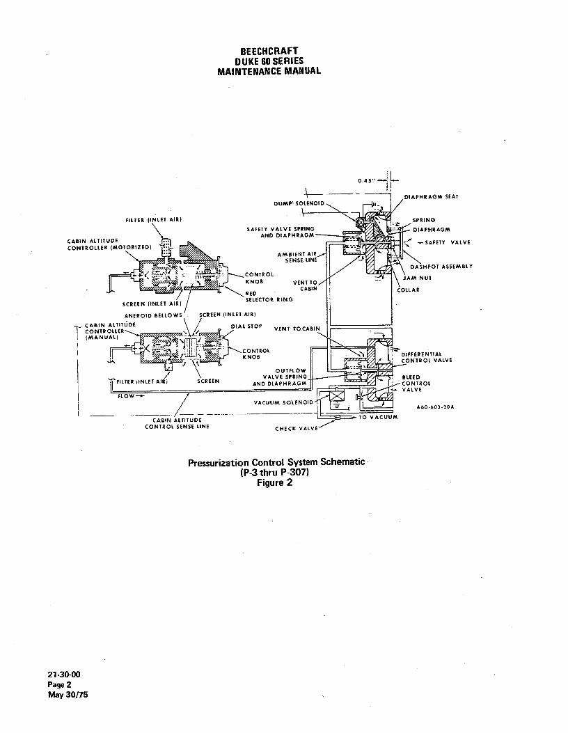
BEECHCRAFTDUKE60SERIES
MAINTENANCEMANUAL
0.45
DIAPHRAGM SEATDUMP'500ENOID 11
FILTER (INLET AIR)SPRING
SAFETY VALVE SPRING DIAPHRAGMCABIN ALTITUDE AND DIAPHRAOM
CONTROLLER (MOTORIZED) -SAFETY VALVE
AMWIENT AIR/SENSE LINE
CONTROLDASHPOT ASSEMBLY
r KNOB VENT TO/ JAM NUT
REDCABIN COLLAR
SCREEN (INLET AIR) SELECTOR RING
ANEROtD BELLOWS SCREEN (fNLET AIR)
CABIN ALTITUDECONTROLLER DIAL STOP VENT TOCABIN
l (MANUAL)
CONTROLDIFFERENTIALCONTROL VALVE
FitTER (INLET AIR SCREEN
VALVEUN BLEED
AND DIAPHRAGM CONTROL
FLOW VALVE
VACUUM SQLINOIDA60-603-20A
CABIN ALTITUDE TO VACUUMCONTROL SENSE LINE
CHECK VALVE
Pressurization Control System Schematic(P-3 thru P-307)
Figure 2
21-30-00
Page 2May 30/75

BEECHCRAFTDUKE60 SERIES
MAINTENANCEMANUAL
indicates that the cruise altitude and the cabin altitude are accomplished with a minimum of abrupt cabin pressureidentical (unpressurized). The 4.6 psi line indicates the change by turning the selector dial very slowly andmaximum differential pressure obtainable in the cabin. To monitoring the rate of change on the cabin pressuredetermine the lowest cabin altitude which can be indicator. A time lapse of approximately two minutes formaintained for a given cruise altitude: enter the graph at each thousand-foot increment change on the dial will effectthe desired cruise altitude and read right to the 4.6 psi a comfortable change of pressure. Rapid cabin pressuredifferential pressure line. Then read down the graph to the changes will be experienced if the altitude selector is movedaltitude which can be maintained in the cabin. quickly before reaching the maximum differential pressure
of 4.6 psi.DIFF. PRESS.PSI.
4.6 CAB/N ALTITUDE CONTROLLER30
74 3 2 1 o (MOTORIZED) (PRIOR TO P-308)
The motorized controller is designed to maintain a constant25 cabin altitude rate of change during airplane climbs and
descents and to make available a means of cabin altitude20 programming. It can best be described as an adjustable
o isobaric controller incorporating a variable speed drivemotor with automatic shut off. The additional controls forthe unit are the red altitude selector ring, the motor rate
15- rheostat and the directional toggle switch. The inner cabin
altitude selector is normally operated with the directionaltoggle switch. The control can be moved to override themotor drive but under normal operation all movement
10 should be made with the toggle switch. The inner scaleshows the cabin altitude when read at the index mark (12o'clock position). The outer scale under the window showsthe selected airplane altitude. The inner scale adjacent to
5. the window shows what the cabin altitude will be whenmaximum differential pressure (4.6 psi) is reached.
To ready the unit for operation, place the rate rheostatknob in the mid-range and insure that the directional toggleswitch is in the off position.
a 5 10 15 20 25 30
CABIN ALTITUDE ~ THOUSANDSOF FEET CAUTIONA60-601-33
In event the directional toggle switch is
i Effectual Pressure Graph positioned improperly, the controller will driveFigure 3 to the end of the scale and damage to the slip
clutch may result.CABIN ALTITUDE CONTROLLER (MANUAL)
| (PRIOR TO P-308) Manually set the cabin altitude controller (inner scale) toapproximately 1,000 feet above the take-off field elevation.
Cabin altitude is maintained by the cabin altitude controller (The red altitude selector ring will turn with the inner scalewith the control anywhere from zero pressure to the when this adjustment is made). Now set the window on themaximum differential of 4.6 psi. red altitude selector ring to 1,000 feet above the planned
airplane's cruise altitude. This will avoid reaching maximumThe controller is rotated until the desired cabin altitude for differential pressure in the cabin prior to achieving cruiseflight is at the 12 o'clock position under the index mark. altitude.Any selected cabin altitude will be maintained during theflight provided the cabin pressure is at or below the After take-off and during the climb when the cabin rate ofmaximum differential pressure. If the cabin reaches the climb has returned to zero, move the directional togglemaximum differential of 4.6 psi and the airplane is still switch to the up position. This gradually climbs the cabinclimbing the cabin altitude will climb with the airplane. to the altitude which is opposite the altitude in the window
on the red selector ring. The controller should be driven atif a cabin altitude change is required in flight it can be a rate to arrive at the cabin altitude shortly before the
21-30-00Page 3
May 30/75

BEECHCRAETDUKE60 SERIES
MAINTENANCEMANUAL
airplane arrives at the cruise altitude. This can be feature of the valve maintains cabin pressure at maximumaccomplished by increasing or decreasing the rate rheostat differential pressure (4.6 to 4.7 psi) only. The differentialknob. A few seconds lag time must be allowed for the control utilizes a diaphragm that applies pressure against apressurization controls to respond and stabilize before spring-loaded needle valve. When cabin pressure reachesreading the cabin altitude rate of climb indicator. The maximum differential pressure, the diaphragm pushescontroller will automatically turn off when the window in against the needle valve, allowing cabin air to bleed off iritothe red selector ring reaches the 12 o'clock position. the :tail section. As cabin air bleeds off, the diaphragmHowever, the directional switch should be placed in the ahows the needle valve to return to its normal position;OFF position. thus the diaphragm modulates the needle valve between the
open and closed position to maintain the proper pressure.CAUTION
Onsserials P-3 through P-126, except P-123, the safety valveIn the event the directional toggle switch is incorporates a solenoid valve which is wired to the landingpositioned improperly, the controller will drive gear safety switch. When the airplane touches down, theto the end of the scale and damage to the slip safety valve will energize and dump the cabin pressureclutch may result. overboard. A manual dump switch, located on the RH
subpanel will also energize the solenoid and dump pressureFor normal descent turn the red selector ring until the overboard while in flight. On serials P-123, P-127 and after,window is opposite the altitude which is 1,000 feet above the:dump solenoid is actuated by the dump switch only,the landing altitude. After departing the original altitude, while the vacuum solenoid is actuated by the landing gearplace the directional toggle switch in the down position. In safety switch. The safety valve functions the same as thethe event that a rapid descent rate is required, set the rate differential control section of the differential control valverheostat for an increased rate of descent so as to maintain a except that the pressure setting is slightly higher.higher airplane altitude than cabin altitude throughout thedescent. - A:solenoid valve is also located on the differential control
value. The primary function.of this solenoid is to eliminateif the cruise altitude selected is less than 11,000 feet or pressurization fluctuation during ground run-up and flightcorresponding cabin altitude (below the window) is less in the unpressurized mode. When energized, the solenoidthan the take-off field elevation, then the controller need valve allows vacuum to be applied to the control diaphragmnot be moved. However, if the landing altitude is less than which holds it in the open position allowing cabin pressurethe take-off field elevation then the controller can be driven toffreely dump overboard. The solenoid valve is energizeddown to the selected cruise altitude. when the manual dump switch is in the dump position or
anyttime the airplane is on the ground. The vacuum sourceDIFFEREN T/AL CON TROL VAL VE AND is an ejector, located in the aft fuselage which obtains its er
i SAFETY VAL VE (PRIOR TO P-308) suggy from the instrument air or deicer system.
A differential control valve and a safety valve are located onthe forward side of the aft pressure bulkhead. PRESSUR/ZA T10N TESTSWITCH
Apressurization press-to-test switch is located on the RH
I NOTE sulppanel. The press-to-test switch de-energizes the solenoidvalves on the differential control valve and the safety valve
On airplane serials P-247 and after the outflow . so¾e pressurization system can be checked during groundvalve and safety valve are mounted within a box run-up. Pressurization ground check may be accomplishedstructure which is a portion of the aft pressure asifollows:bulkhead.
-=
- a. Place the manual dump switch in the pressureThe differential contfoi valve regulates cabin pressure up to position and the firewall shut-off valves in the openmaximum differential pressures of 4.6 to 4.7 psi. A position.diaphragm in the valve, controlled by the cabin altitude b. Run the engines at 2,000 rpm and press thecontrol, closes but allows a preset amount of cabin air to press-to-test switch.bleed off into the tail section through an adjustable bleed c.
.A momentary indication of a descent in cabin
valve. This maintains the selected cabin altitudes up to attitude on the cabin rate-of-climb indicator shows that themaximum differential pressure. The differential control system will pressurize.
21-30-00Page 4May 30/75
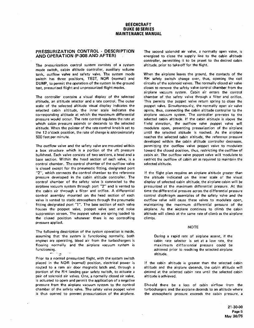
BEECHCRAFTDUKE60SERIES
MAINTENANCEMANUAL
PRESSURIZATION CONTROL - DESCRIPTION The second solenoid air valve, a normally open valve, isAND OPERATION (P-308 AND AFTER) . energized to close the supply line to the cabin altitude
controller, permitting it to be preset to the desired cabinThe pressurization control system consists of a system altitude, prior to take-off for the flight.mode switch, cabin altitude controller, auxiliary volumetank, outflow valve and safety valve. The system mode When the airplane leaves the ground, the contacts of theswitch has three positions, TEST, NOR (normal) and RH safety switch change over, thus, opening the coilDUMP, to permit the operation of the system in the ground circuits of the solenoid valves. The normally closed air valvetest, pressurized flight and unpressurized flight modes. closes to remove the safety valve control chamber from the
airplane vacuum system. Cabin air enters the controlThe controller contains a visual display of the selected chamber of the safety valve through a filter and orifice.altitude, an altitude selector and a rate control. The outer This permits the poppet valve return spring to close thescale of the selected altitude visual display indicates the poppet valve. Simultaneously, the normally open air valveselected cabin altitude, the inner scale indicates the opens, thus, connecting the cabin altitude controller to thecorresponding altitude at which the maximum differential airplane vacuum system. The controller pre-rates to thepressure would occur. The rate control regulates the rate at selected cabin altitude. If the cabin altitude is above thewhich cabin pressure ascends or descends to the selected field elevation, the outflow valve poppet valve willaltitude. When the pointer of the rate control knob is set to modulate open, preventing pressurization of the airplanethe 12 o'clock position, the rate of change is approximately until the selected altitude is reached. As the airplane500 feet per minute. reaches the selected cabin altitude, the reference pressure
developed within the cabin altitude controller decreases,The outflow valve and the safety valve are mounted within permitting the outflow valve poppet valve to modulatea box structure which is a portion of the aft pressure toward the closed position, thus, restricting the outflow ofbulkhead. Each valve consists of two sections, a head and a cabin air. The outflow valve poppet valve will modulate tobase section. Within the head section of each valve, is a restrict the outflow of cabin air as required to maintain thecontrol chamber. The control chamber of the outflow valve selected altitude.is closed except for the pneumatic fitting, designated port"2", which connects the control chamber to the reference If the flight plan requires an airplane altitude greater thanpressure developed in the cabin altitude controller. The the altitude indicated on the inner scale of the visualcontrol chamber of the safety valve is connected to the display of selected cabin altitude, the airplane cabin will beairplane vacuum system through port "2" and is vented to pressurized at the maximum differential pressure. At thisthe cabin air through a filter and orifice. A differential time the differential pressure across the differential pressurecontrol assembly mounted on the head section of each control diaphragm assemblies of the safety valve and thevalve is vented to static atmosphere through the pneumatic outflow valve will cause these valves to modulate open,fitting designated port "1". The base section of each valve maintaining the maximum differential pressure of thehouses the poppet valve, poppet valve seat and noise airplane. As the airplane continues to climb the cabinsuppression screen. The poppet valves are spring loaded to altitude will climb at the same rate of climb as the airplanethe closed position whenever there is no controlling climbs.pressure applied.
NOTEThe following description of the system operation is made,assuming that the system is functioning normally, both During a rapid rate of airplane assent if theengines are operating, bleed air from the turbochargers is cabin rate selector is set at a low rate, theflowing normally and the airplane vacuum system is maximum differential pressure could befunctioning. achieved prior to reaching the selected airplane
altitude.Prior to a normal pressurized flight, with the system switchplaced in the NOR (normal) position, electrical power is If the cabin altitude is greater than the selected cabinrogted to a ram air door magnetic latch and, through a altitude and the airplane decends, the cabin altitude willportion of the RH Ianding gear safety switch, to actuate a decend at the selected cabin rate until the selected cabinpair of solenoid air valves. One, a normally closed air valve, altitude is achieved.is actuated to open and permit the application of a negativepressure from the airplane vacuum system to the control Should there be a loss of cabin airflow from thechamber of the safety valve. The safety valve poppet valve turbochargers and the airplane decends to an altitude whereis thus opened to prevent pressurization of the airplane. the atmospheric pressure exceeds the cabin pressure, a
21-30-00Page 5
May 30/75

BEECHCRAFTDUKE80 SERIES
MAINTENANCEMANUAL
negative pressure differential will exist across the inner air valve opens to connect the control chamber of thediaphragms of both the outflow valve and the safety valve. safety valve to the airplane vacuum system. The safety valveWhen the control chamber-to-atmosphere pressure poppet valve is thus opened, permitting the cabin air flowdifferential is sufficient to overcome the force of the to exhaust to the atmosphere without restriction.poppet valve return springs, the poppet valves will openpermitting air at atmospheric pressure to flow into the When the airplane touches down after a pressurized flight,cabin counteracting the negative pressure differential. the;actuation of the RH landing gear safety switch will
again energize the two solenoid air valves to open the safetyDepressurizing the cabin for emergencies, such as smoke in valve poppet valve and to block the source of vacuum fromthe cabin, may be accomplished by placing the mode select the cabin air controHer.switch in the DUMP position. The normally closed solenoid
21-30-00PageSMay 30/75
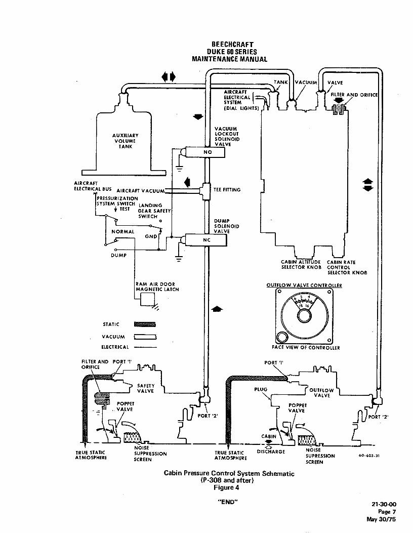
BEECHCRAFTDUKE60SERIES
MAINTENANCEMANUAL
TANK VACUUM VALVE
AIRCRAFT FILTERAND ORIFICEELECTRICALSYSTEM(DIAL LIGHTS)
VACUUMLOCKOUT
AUXILIARY SOLENOIDVOLUME VALVE
TANKNO
AIRCRAFTELECTRICALBUS AIRCRAFT VACUUM TEE FITTING
PRESSURIZATIONSYSTEM SWITCH LANDING
TEST GEAR SAFETYSWITCH
o DUMP• SOLENOID
MALG
VALVE
CABIN ALTITUDE CASIN RATESELECTOR KNOB CONTROL
SELECTOR KNOB
RAM AIR DOOR OUTFLOW VALVE CONTROLLERM C LATCH
STATIC RVACUUM i )ELECTRICAL FACE VIEW OF CONTROLLER
FILTERAND PORT T PORT TORIFICE
PLUG OUTAFLLOEW
POPPET POPPETVALVE VALVE ¡
PORT "2· POf T '2'
CABIN
TRUE STATICSNOlP
ESSION TRUE STATIC DIS ARGE SNUPRSEESSION6 3-31
ATMOSPHERE SCREEN ATMOSPHERE SCREEN
Cabin Pressure Control System Schematic(P-308 and after)
Figure 4
"END" 21-30-00Page 7
May 30/75

BEECHCRAFTDUKE60 SERIES
MAINTENANCEMANUAL
PRESSURIZATION CONTROLS - NOTEB MAINTENANCE PRACTICES (P-3 THRU P-307)
Tighten the differential control valve ELBOWCABIN AL TITUDE CONTROLLER FILTER or, the safety valve TEE fitting to 50 ± 10(MOTORIZED) inch-pounds and secure with safety wire.
A cabin altitude controller filter is utilized on Duke serials c. On airplane serials P-247 and after; install the plateP-229 and after, and those prior airplane's which have over the differential control valve and the safety valve.complied with Service Instructions 0528-453 that have the Secure it with the two AN4-5A bolts, top and bottom, andoptional motorized cabin altitude controller installed. sixteen AN3-5A bolts. Tighten the bolts evenly to a torque
of 50 to 70 inch-pounds for the AN4-5A bolts, and 20 toThe filter is designed to improve filtration and prevent the 25 inch-pounds for the AN3-5A bolts.poppet valve from sticking due to tobacco tars and othercontaminents. Under normal operating conditions theaverage life of the filter is 1,000 hours. This will vary WARNINGaccording to extremes in cabin smoke density. Anindication of need for filter replacement would be a slow The airplane must not be pressurized prior toresponse to variations in altitude. installation of the plate.
d. Install the access door on the lower LH fuselage.DIFFEREN TIAL CONTROL VALVE AND e. Reinstall the upholstery panetSAFETY VALVE REMOVAL
DIFFERENTIAL CONTROL VALVE ANDa. Remove the upper and middle upholstery panels SAFETY VAL VEADJUSTMENT
from the forward side of the aft lower pressure bulkhead
Imaking the valve accessible. On airplane serials, P-247 and NOTEafter, remove the plate which is attached by two AN4-5Abolts and sixteen AN3-5A bolts, to gain access to the Check the differential control valve and safetydifferential control valve and the safety valve. va Ive for adjustment every 300 hours or
b. Loosen and remove all necessary plumbing from annually.the valve. Cap open plumbing to keep shop soil, dirt andforeign objects from entering. The differential control valve and safety valve adjustments
c. Remove the access door on the lower LH fuselage, may be made in accordance with PRESSURIZATIONjust aft of the rear pressure bulkhead. SYSTEM ADJUSTMENT PROCEDURES. For information
d. Station a man inside the aft fuselage to remove the relating to overhaul and cleaning procedures, refer tosix attaching bolts and remove the valve. Component Maintenance Manual, P/N 60-590001-27.
DIFFERENTIAL CONTROL VALVE AND PRESSURIZATION SYSTEM ADJUSTMENTSAFETY VALVE INSTALLATION PROCEDURES
a. Station a man inside the aft fuselage to position a. Remove the middle upholstery panels from the aftthe valve and install the six attaching bolts. pressure bulkhead to provide .access to the differential
control valve and safety valve.
Ib. Open the bleed control valve 1-1/4 turns
NOTE counterclockwise.c. Preset the cabin altitude controller to the nearest
Tighten the attaching bolts to a torque of 15 index mark above field altitude. (Minimum of 1,000 feet.)inch-pounds. d. Adjust the dashpot spring to position the
diaphragm approximately 0.45 inch from valve mountingb. Remove the caps and install all plumbing to the face surfaœ.
valves. e. Check ram air door for resistance to opening by
21-30-00Page 201
May 30/75

BEECHCRAFTDUKE60 SERIES
MAINTENANCEMANUAL
pushing with a long stiff rod with pressurization switch in CABIN ALTITUDE CONTROLLER REMOVALpressurization mode and power on, (MANUAL)
f. Cabin bleed-off rate at 4.6 psi should not exceed6,000 fpm. (Required only if excessive leak rate is a. Remove the four attaching screws at the subpanel.suspected.) b. Loosen and remove plumbing from the controlle_r.
g. Execute a normal take-off and record maximum Cap open plumbing to keep shop soil, dirt and foreigncabin descent which occurs approximately 20 seconds after objects from entering.lift-off. Acceptable range is 300 to 1,000 fpm. c. Remove the controller.
h. Place the airplane in a 1,000 fpm climb at normalclimb power and record maximum cabin descent as the C A B I N A L T/ TUDE CO N TR OLLERairplane begins to pressurize. Maximum descent rate is 500 INSTALLATION (MANUAL)fpm.
i. After climbing through an altitude 2,000 feet a. Remove plumbing cap and install plumbing toabove the altitude selected on the cabin altitude controller, controller.adjust the bleed control valve (if required) as follows: b. Position the controller in the subpanel.
1. If the cabin climbs as the airplane climbs, close c. Install the four attaching screws at the subpanel.the bleed control valve to obtain a zero rate-of-climb on thecabin rate-of-climb indicator. C A B I N A LT I TUDE CONTROLLER
ADJUSTMENT (MANUAL)NOTE
a. Make a reference mark on the outer ring of theBecause of the sensitivity of the pressurization controller controi head to match the triangular mark on thecontrol system, the bleed control valve should edge light panel directly above the control.be moved in increments of no more than 1/8 : b. Remove the controller from the subpanel.turn.
2. If the cabin dives as the airplane climbs, OPEN NOTEthe bleed control valve to obtain a zero rate-of-climb on thecabin rate-of-climb indicator- The controller should be removed from the
j. Level the airplane at an altitude approximately subpanel prior to take-off if the need for8,000 feet above the selected cabin altitude and compare adjustment is anticipated.the selected altitude on the controller with the indicatedcabin altitude on the cabin attimeter. If the difference in c. Loosen the control head retention Allen screw andthe two altitudes is in excess of 500 feet, the control head slide the control head off the bellows shaft without turningon the cabin altitude controlfer should be removed and the shaft.adjusted to correspond with the altitude on the cabinaltimeter.
NOTENOTE
Do not loosen the slot head screw in the knobThe manual controller should be removed from on the control head.the subpanet prior to take-off if the need foradjustment is anticipated. d. Hold the outer ring of the control head and rotate
the cabin altitude selection knob until the actual cabink. After landing, if lift-off descent is excessive and altitude, as indicated on the cabin altimeter, aligns with the
isobaric descentTs srnall, as fecorded in steps "g." and "h.", reference mark (see step "a.").adjust the dashpot clockwise approximately 1/2 turn for e. Align the guide pin and slide the control head backeach 400 fpm. Maximum clockwise adjustment is one turn. on the bellows shaft without turning the shaft.
1. If lift-off descent is small and isobaric descent is f. Secure the control head in place with the AIIenexcessive, as recorded in steps "g." and "h.", adjust the screw and reinstall the controller in the subpanel.dashpot counterciockwise approximately 1/2 tum for each400 fpm. Eor proper information relating to overhaul and cleaning
m. Reinstall the upholstery panels to the aft pressure procedures refer to Component Maintenance Manual, P/Nbulkhead. 60-590001-27.
21-30-00Page 202May 30/75

BEECHCRAFTDUKE60SERIES
MAINTENANCEMANUAL
CABIN ALTITUDE CONTROLLER REMOVAL For proper information relating to overhaul and cleaning(MOTORIZED) procedures refer to Component Maintenance Manual, P/N
60-590001-27.a. Remove the four attaching screws at the subpanel.b. Remove the screw, washer and support clamp, PRESSUR/ZA T/ON TEST PROCEDURE
located behind the subpanel, from the controller.c. Loosen and remove plumbing from the controller. (Refer to "1.a." and "1.b." under TROUBLESHOOTING
Cap open plumbing to keep shop soil, dirt and foreign PRESSURIZATION SYSTEM.objects from entering.
d. Remove the controller. This test provides a means of isolating the cabin altitudecontrol to determine if it or the differential control valve is
CA B / N A LT / TUDE CON TR OLLE Ñ defective when the system cannot be properly pressurized.INSTALLATION (MOTORIZED)
a. Remove the upholstery panels providing access toa. Remove plumbing cap and install plumbing to the differential control valve at the aft pressure bulkhead.
controller. b. Disconnect the cabin altitude control sense lineb. Position the controller in the subpanel. from the differential control valve.c. Install the support clamp on the controller and c. Pull the pressurization control circuit breaker.
attach with the screw and washer. d. Start both engines and VERY SLOWLY increased. Install the four attaching screws at the subpanel. Power to a minimum of 20 in. Hg manifold pressure (cabin
rateof-descent not to exceed 1,000 feet per minute).CABIN ALTITUDE CONTROLLERADJUSTMENT (MOTORIZED)
NOTE WARNING
The controller does not need to be removed Increasing power rapidly could cause the cabinfrom the subpanel for this adjustment. to pressurize to maximum differential within a
short time, to the subsequent discomfort ofa. Loosen the control head retention Allen screws personnel in the airplane-
and slide the control head off the bellows shaft withoutturning the shaft.
e. If the cabin rate-of-climb indicator shows a descentNOTE as power is increased above a minimum of 20 in. Hg
manifold pressure, the cabin altitude control is defective.Do not loosen the slot head screw in the knob f. If the cabin rate-of-climb does not show a descenton the control head. as power is increased above a minimum of 20 in. Hg
manifold pressure, the isobaric control portion of theb. Rotate the control head until the altitude in the 12 differential control valve is defective. The differential
o'clock position on the selection knob is the same as the control portion of the valve may also be checked byactual cabin altitude, as indicated on the cabin altimeter. allowing the cabin to pressuri2e to maximum differentisi
c. Align the guide pin and slide the control head back pressure. If cabin pressure stabilizes at 4.6 to 4.7 psi ason the bellows shaft without turning the shaft. monitored by the cabin differential pressure gage, the
differential control portion of the valve is functioningCAUTION properly.
g. SLOWLY decrease power until the cabin isIncorreçt positioning of the control head on the depressurized, then shut down both engines.bellovis shaft may cause improper travel h. If any components were found defective, replaceclearances and result in damage to the slip them and repeat the test.clutch. i. Reset the pressurization control circuit breaker.
j. Reconnect the cabin altitude controll sense line tod. Tighten the Allen screws to secure the control head the differential control valve, then reinstall the upholstery
on the bellows shaft. panets on the aft pressure bulkhead.
21-30-00Page 203
May 30/75

BEECHCRAFTDUKE60SERIES
MAINTENANCEMANUAL
PRESSURIZATION CONTROL - MAINTENANCE evenly to a torque of 50 to 70 inch-pounds for the AN4-SaPRACTICES (P-308 AND AFTER) and 20 to 25 inch-pounds for the AN3-5A bolts.
OU7FLOW VALVEAND SAFETY VALVEREMOVALWARNING
The safety valve and the outflow valve are nearly identical.The safety valve is installed in the lower position and the The airplane must not be pressurized prior tooutflow valve is installed in the upper position. installation of the plate.
a. Remove the upholstery panel from the aftpressure bulkhead. g. Reinstall the access door on the lower LI
b. Remove the plate to gain access to the outflow fuselage, aft of the rear pressure bulkhead.and safety valves. The plate is secured with two AN4-5A h. Reinstall the upholstery panel.bolts and sixteen AN3-SA bolts.
c. Loosen and remove the plumbing, as necessary,to permit removal of the valve. Tag the plumbing asremoved to facilitate reinstallation. Cap all open plumbing OU TFL OW VAL VE A NO SA FE TY VA L Vaand valve fittings to prevent shop soil and foreign objects ADJUSTMENTfrom entering.
d. Remove the access door on the lower LH The outflowvalve and the safety valve are each preset afuselage, just aft of the rear pressure bulkhead. the factory to regulate the cabin pressurization to
e. Station a man inside the aft fuselage to remove maximum differential pressurization of 4.6 ± .1 psi. Fielthe six attaching nuts and washers securing each valve. adjustment of these valves is not recommended. In th
f. Remove the valve. event of a malfunction, the valves should be returned tg. Remove and discard the old gasket. Beech Aircraft Corporation in exchange for an Overhaulet
Exchange unit.
OUTFLOW VALVE AND SAFETY VALVEINSTALLATION
OU7FLOW AND SAFETY VALVECLEANINGa. Remove all traces of the old gasket.b. Station a man inside the aft iuselage to install the
attaching washers and nuts that secure each valve. CAU770Nc. Install the safety valve in the lower position and/or
the outflowvalve in the upper position, using a new gasket. The outflowand safety valves are preset at thed. Secure the valve to the pressure bulkhead factory and field adjustment is not
structure by installing a washer and a nut at each of the six recommended. Any time the valve seal isplates. Tighten the nuts evenly to a torque of 4 ± 1 inch- broken, the WARRANTY (6 months in duration)pounds. is VOIDED.
I NOTE Fluctuation of cabin pressure often indicates ditty outfkand safety valves. The seats of these valves should
Earlier airplane serials have valves with flared cleaned at 100 hour inspections, or more frequentlyfittings, while later serials, equipped with plastic needed. The inspection and cleaning of the valve seat aoutflow valves, use a beaded tube fitting and bellows may be accomplished by the following suggestclamps to secure the plumbing. Use water only procedure:as a lubricant on -EVA tubing being installedover beaded tubing or fittings. a. Remove the aft fuselage access panel from ti
lower LH fuselage aft of the aft pressure bulkhead.b. Compress the bellows to permit inspection a
e. Remove the caps and install the plumbing as cleaning.tagged when the plumbing was removed. c. Clean the bellows and the inner rim of the vat
f. Install the plate over the outflow and safety housing where the bellows contacts the housing when tvalves. Secure it with the two AN4-SA bolts, at top and bellows is extended, using a clean rag dampened wbottom, and the sixteen AN3-5A bolts. Tighten the bolts isopropyl alcohol (45, Chart 207, 91-00-00).
21-so-ooPage 204Feb 22/80

BEECHCRAFTDUKE60 SERIES
MAINTENANCEMANUAL
SAFETY VALVE FILTER AND OR/FICE CLEANING b. If the cabin pressure goes to maximum differentialand cannot be controlled at 1/2 psid below maximum
The filter and orificein the head section of the safety valve differential, the outflow valve must be replaced.should be removed, cleaned and inspected every 1,000 c. The outflow valve is removed and installed ashours. The filter may be cleaned by the following suggested described in this Chapter under the headings OUTFLOWprocedure: VALVE AND SAFETY VALVE REMOVAL and OUTFLOW
VALVE AND SAFETY VALVE INSTALLATION.a. Remove the upholstery panel.b. Remove the plate to gain access to the safety
valve. The plate is secured with two AN4-5A bolts and SAFETY VALVE GROUND CHECKsixteen AN3-5A bolts.
c. Remove the filter from the head section of the a. Connect a regulated cabin pressurization test unitsafety valve. Do not lose the packing. to the airplane as outlined under the heading CABIN
d. Remove the retaining ring from the filter assembly PRESSURIZATION LEAKAGETEST (P-4 and after) in thishousing. Remove one screen, the copper ribbon and the Chapter. (Do not pressurize at this time.)remaining screen from the housing of the filter assembly. b. Working through the access opening behind the
e. Wash both screens, the copper ribbon, and the aft pressure bulkhead, locate the line that connects thefilter assembly housing in solvent (15. Chart 207, 91-00-00). dump solenoid valve to the safety valve and disconnect theEnsure that the orifice of the filter housing is free of foreign line from the solenoid valve.material. c. Connect a regulated vacuum source to the line
f. Install one screen in the housing of the filter which was disconnected from the solenoid valve. (Do notassembly. Install the copper ribbon in the filter assembly apply vacuum at this time.)housing. Do not over compress the ribbon. Install the d. Pressurize the cabin to 3 psid.remaining screen and secure the filter in the housing using e. Slowly apply regulated vacuum to the safetythe retaining ring. valve. If the valve opens before the vacuum reaches 4
g. Install the filter assembly in the safety valve, using inches Hg indication on the test unit, the valve is operatingthe packing removed with the filter assembly. Tighten to a satisfactorily. If more than 4 inches Hg are required to opentorque of 15 to 20 inch-pounds. the safety valve, the valve must be replaced.
h. Reinstall the plate over the outflow and safetyvalves. Secure it with the two AN4-5A bolts, at top andbottom, and the sixteen AN3-5A bolts around the perimeter CABIN ALTITUDE CONTROLLER REMOVALof the plate. Tighten the bolts evenly to a torque of 50 to 70inch-pounds for the AN4-5A bolts and 20 to 25 inch-pounds a. Remove the knobs, handles, screws, etc. tofor the AN3-5A bolts. facilitate the removal of the edge-lighted panel from the RH
inboard subpanel.WARNING b. Tag the plumbing as removed to facilitate
reinstallation. Loosen and remove all plumbing from theThe airplane must not be pressurized prior to cabin pressurization controller, as necessary to permitinstallation of the plate. removal of the controller. Cap all open plumbing to keep
shop soil and foreign material from entering the plumbingand the controller. Disconnect the electrical wiring from the
i. Reinstall the upholstery panel. controtter lamp wires.c. Remove the three screws securing the cabin
altitude controller to the printed circuit board of the RHFUNCTIONAL TEST OF OU7FLOW VALVE AND inboard subpanel.SAFETY VALVE (P-308 and after) d. Remove the cabin altitude controller.
OUTFLOW VALVE FLIGHT CHECKCABIN ALTITUDE CONTROLLER INSTALLATION
TNe following check must be accomplished with the airplanein itight. a. Install the cabin altitude contro!!er in the printed
circuit board of the RH inboard subpanel. Secure with thea. If the cabin pressure can be controlled at 1/2 psid three screws.
(pounds per square inch differential) less than maximum b. Remove the caps and reinstall the plumbing asdifferential of 4.6 ± .1 psi, the outflow valve is operating tagged during removal. Reconnect the wiring to thesatisfactorily. controller lamps.
21-30-00Page 205
Feb 22/80
BEECHCRAFTDUKE60 SERIES
MAINTENANCEMANUAL
c. Install the edge-lighted panel. Secure with the cabin pressure bulkhead and secure with the two screwsscrews. Replace the knobs and handles. previously removed.
. b. Remove the caps and connect the plumbing tothe=auxiliaryvolume tank.
CABIN PRESSUR/ZATION CONTROLLERADJUSTMENT
The cabin pressurization controller is preset at the factory. PRESSUR/ZA T/ON TEST PROCEDUREField adjustments and maintenance of the controiter is not (Ri308 AND AF7ER)recommended. In the event of a malfunction, the cabinpressurization controller should be returned to Beech The pressurization system may be functionally checked forAircraft Corporation in exchange for an Overhauled- operation by the following suggested procedure:Exchanged unit.
a. If the outflowvalve and the safety valve are to betested for proper differential pressure operation, proceed as
CAB/N ALT/TUDE CONTROLLER FILTER AND follows:ORIFICE CLEAN/NG
1. Remove the upholstery panel from the aftThe filter and orificein the cabin attitude controller should be pressure bulkhead. Remove the access plate to gain accessremoved, cleaned, and inspected every 500 hours. The filter to the outflow valve and safety valves.may be removed and cleaned by the following suggested 2. Loosen and remove the plumbing from theprocedure: true static air vent (port 1) on the head section of each
valve. (Tag each tube to facilitate reinstallation.) Add aa. Remove the filter assembly from the housing of section of tubingto each static air vent of sufficient length to
the cabin altitude controller. Do not lose the packing. reach through the holes in the access plate after it has beenb. Remove the retaining ring from the filter assembly reinstalled, since the airplane must not be pressurized prior
housing. Remove one screen, the copper ribbon and the to installation of the plate. Provide a means of disconnectingremaining screen from the housing of the filter assembly. and capping each true static air vent with the plate
c. - Wash both screens, the copper ribbon and the reinstalled. Tag each tube for identification during the test.filter assembly housing in solvent (15, Chart 207, 91-00-00). 3. Reinstall the plate. Secure the plate andEnsure that the orifice of the filter housing is free of foreign tighten the bolts evenly to a torque of 50 to 70 inch-poundsmaterial. for the AN4-5A bolts at the top and bottom of the plate and
d. Install one screen in the housing of the filter 20 to 25 inch-pounds for the remaining bolts.assembly. Install the copper ribbon in the filter assemblyhousing. Do not over compress the copper ribbon. Installthe remaining screen and secure the filter in the housing WARNINGusing the retaining ring.
e. Install the filter assembly in the cabin altitude The airplane must not be pressurized prior tocontroller using the packing removed with the filter installation of the plate.assembly. Tighten to a torque of 15 to 20 inch-pounds.
b. Close and secure the cabin door.AUX/L/ARY VOLUME TANK REMOVAL c. Rotate the cabin rate control selector knob to the
12 o'clock position.a. Loosen and remove the plumbing. Cap the d. Select a cabin altitude that is approximately 500
plumbing and the auxiliaryvolume tank to prevent shop soil, feet above the field elevation.dirt and foreign material from entering the auxiliary volume e. Set the airplane brakes and start the engines astank or the plumbing. instructed in the applicable Duke Pilot's Operating Manual.
b. Remove the two screws securing the auxiliary Operate both engines at a minimum power setting of 20 in.volume tank to the forward cabin pressunzation bulkhead. Hg manifold pressure to establish a steady flow of cabin air.Remove the tank. f. Open the pressurization system circuit breaker.
Note that the safety valve on the aft pressure bulkheadcloses and the airplane starts to pressunze.
AUX/L/ARY VOLUME TANK INSTALLAT/ON g. Select a cabin altitude that is approximately1,500feet below the field elevation. The cabin will pressurize at a
a. Mount the auxiliary volume tank on the forward rate-of-change rate to decrease the cabin altitude.
21-3040Page 206Feb 22/80
BEECHCRAFTDUKE60 SERIES
MAINTENANCEMANUAL
h. Rotate the rate control selector knob outflow valve and the safety valve. Reinstall the plate.counterciockwise and note a reduction in rate-of-change of Tighten the bolts evenly to a torqueof 50 to 70 inch-poundscabin pressurization. for the AN4-5A bolts at the top and bottom of the plate and
i. Rotate the rate control selector knob clockwise 20 to 25 inch-pounds for the remaining bolts.and note a reduction in the rate-of-change of cabinpressurization. WARNING
j. Rotate the cabin altitude selector knob to the fullcounterciockwise stop and select a rate-of-change that is The airplane must not be pressurized prior tocomfortable. The cabin-to-atmosphere pressure differential installation of the plate.will increase. The value of the differential pressure attainedwill depend upon the field elevation at which the test isconducted. r. Reinstall the upholstery panel.
k. When the cabin pressure has stabilized,disconnect and cap the plumbing from the cabinpressurization controller port labeled VACUUM. Cap the CABINPRESSUR/ZATIONLEAKAGETEST(P-4andplumbing and the controller port to prevent the entrance offoreign materials. (Figure 201)
The cabin-to-atmosphere pressure differential will now Test equipment is available for ground testing the cabin forincrease to the normal positive differential pressure setting pressurization leaks and for troubleshooting theof the outflow valve and the safety valve. pressurization system. Such equipment must be capable of
delivering 4.50 psi of air at 80 cubic feet per minute andmust be protected by a complete safety system to prevent
NOTE damage to the airplane. The test unit listed in the followingparagraph consists of an electric motor and blower
Cabin pressure will increase to the maximum assembly, a dry air filter, a flowmeter, a cabin pressuredifferential value at an uncontrolled rate when gage, and a large relief valve to protect the pressure vessel
the vacuum line is disconnected. of the airplane.
I. After the cabin pressure has again stabilized, note NOTEthe readings on the CABIN ALT and DIFF PRESS indicator.
m. Disconnect the true static air vent which is It should be noted that the test unit to be usedconnected to the outflow valve. (Refer to step "a." of this must be set at the psi of pressurization forprocedure.) The DIFF PRESS indicator shall indicate a which the airplane is designed if the safetychange that is no greater than .1 psi. system of the test unit is to fulfill its function.
n. Reconnect the static air vent to the outflow valveand disconnect and cap the true static air vent from thesafety valve. The DIFF PRESS indicator should again The units listed in the following paragraph, TESTindicate a change that is not greater than .1 psi. Reconnect EQUIPMENT, also include a pneumatic air system thatthe safety valve true static air vent. delivers from zero to 30 pounds of air at 25 cubic feet per
o. Reconnect the plumbing to the VACUUMfitting of minute for checking the deicer boot system, and pressurethe cabin pressurization controller. The cabin altitude will instruments.return to the altitude selected on the cabin pressurizationcontroller. The cabin altitude, as indicated on the CABINALT indicatorsshould stabilize at an altitude within 500 feet TEST EOUIPMENT (P-4 and after)of the selected cabin altitude.
p. Rotate the cabin altitude selector to select an The following pressurization test units, or their equivalent,altitude that is approximately 500 feet above the field may be utilized for the cabin pressurization leakage test.elevation. After the cabin altitude has again stabilized, resetthe cabin pressurization circuit breaker. Shut down the a. Cabin Pressurization Test Unit: Manufactured byengines as described in the applicable Duke Pilot's Kitco Tool and Die Inc., 21 Water Street, Mill Hall, PA.Operating Manual. 17751.
q. Remove the plate over the outflow and safetyvalves. Remove the test plumbing installed in step "a.", 1. Model 1200 - for domestic use.above. Reconnect the true static air vent tubes to the 2. Model 1300 - for export use.
21-30-00Page 207
Feb 22/80

BEECHCRAFTDUKE60 SERIES
MAINTENANCEMANUAL
NOTE c. Place high strength webbing, P/N 60-000000-D939-1 or equivalent in position over the pressure vessel
The test equipment hoses, fumished with the (doors and windows).test unit, may be connected in only one (either), d, Connect a 2-1/2 inch air supply hose between theor both nacelles. The TEST EQUIPMENT text test unit (PRESSURIZING AIR fitting)and the flexible ducts,and Figure 201 illustrates the test equipment forward of the LH and RH firewall.hoses connected in both nacelles. e. Connect the PNEUMATICAIR fitting on the test
Unit to the pneumatic line in each nacelle, forward of thepressure regulator.
b. Use low pressure hose, 2 1/2 inches in diameter,to connect the PRESSURIZING AIR fitting of the test unit tothe flexible ducts, forward of the LH and RH firewall's. NOTE
c. Two pieces of 1/4-inch high pressure hose is usedto connect the PNEUMATIC AIR fitting on the test unit to the Ensure that all connections are secure at thepneumatic line in each nacelle, forward of the pressure airplane and at the test unit. Ensure that all "T"regulator. and/or "Y" fittings are secure.
d. High pressure hose, 3/8-inch in diameter,connects the lNSTRUMENT AIR or CABIN PRESSUREfitting on the test unit to the brake reservoir sense line at the f. Slowly open the air valve to pressurize the cabin.'orward pressure bulkhead, located in the nose baggage Monitor the RATE-OF-CLIMS and CABIN PRESSUREcompartment. indicators. The rate-of-climb should not exceed 1,000 feet
e. Tee or Y-shaped fittings and clamps to connect per minute to a maximum of 25,000 feet. The cabinthe hoses as described in steps "b" through "d". differential pressure shall not exceed 4.6 ±-.1 psi as
f. High strength webbing or restraining straps to observed on the CABIN PRESSURE indicator.encompass fuselage doors and windows for safety of g. Pressurize the cabin to a differential pressure oftesting personnel during performance of test. (P/N 60- 4.00 ± .50. Allow five minutes for the cabin pressure to000000-D939-1 or equivalent.) stabilize. After stabilization is established, check the cabin
for excessive leakage. A 38 cubic feet per minute leakage ispermissible. If the leakage is indicated at more than 38cubic feet per minute, isolate the cause and repair as
TEST PROCEDURE (P-4 and after) described in the following paragraphs.
a. Gain access to the outflow and safety valves at 1. Check all connections to the pressurethe aft pressure bulkhead. Remove the control port tubing vessel, test unit, and the "T" and/or "Y" fittings in the testfrom both the outflow and safety valves. hoses to ensure that no leaks exist. Repair all leaks and
b. Connect the 3/8-inch high pressure hose from the repeat steps "f." through "g."INSTRUMENT AIR or CABIN PRESSURE fitting on the test 2. If leaks through the outflow or safety valvesunit to the brake reservoir sense line at the fotward pressure are suspected, a slightadjustment of the outflowand safetybulkhead, located in the nose baggage compartment. The valve mounting screws may reduce the leakage rateair supply must be capable of maintaining 4.50 psi. considerably. If the outflow and/or safety valves are
determined to be defective, replace as necessary. Performthe leak test described in steps "f." through "g".
NOTE 3. Check around the windows for leaks, removeand replace windows found to be defective.
Ensure that all windows and doors are closedand securely latched.
NOTE
WARNING Ensure that the test unit is working properly andall gages are accurate.
Personnel who work under pressurizedconditions must be carefully chosen.Pressurization may prove dangerous topersonnel which are overweight, have heart orrespiratory disorders, ear infection, or are not 4. Gain access to the points where the contrc
emotionallystable. cables, electrical wire bundles, plumbing, and landíng ges
21-30-00Page 208Feb 22/80

BEECHCRAFTDUKE60 SERIES
MAINTENANCEMANUAL
retract rods enter the pressure vessel by removing the leaks. Isolate and repair all leaks. Repeat steps "a" throughseats, floorboards, and upholstery. Fill the control cable "g".pressure seals with MIL-G-23827 grease (11, Chart 202, 12-20-00 and Chart 207, 91-00-00) and paint the control h. With the pressure leak test within tolerance,cables, through-out its full travel through the pressure seals depressurize the pressure vessel and remove the safetywith MIL-G-23827 grease (11, Chart 202, 12-20-00 and net.Chart 207, 91-00-00). Spread the electrical wire bundles i. Remove all test hoses from the airplane andapart and apply EC1239A½ sealant around each wire. After connect the hoses between the fuselage and the engines.each wire is covered, wrap Scotch #33 vinyl around the wire j. Install the control port tubing on each outflowandbundle (butted against seal fitting) and inject EC1239A½ safety valves.sealant in the notch of the seal fitting. Apply EC1239B½ k. Remove the plug from the atmosphere port of thesealant to all plumbing fittings at the pressure vessel. outflow valve and ensure that the back pressure test hose isEnsure that the landing gear retract rods pressure boots are removed from the atmosphere vent fitting of the safety valveproperly installed without damage. Perform the (located on the aft side of the aft bulkhead).pressurization leak test as described in "a" through "g". l. Install floorboards, upholstery panels, seats, and
5. Remove all seats, floorboards, and access panels which were removed during the testupholstery panels. Check the complete pressure vessel for procedure.
21-30-00Page 209
Feb 22/80
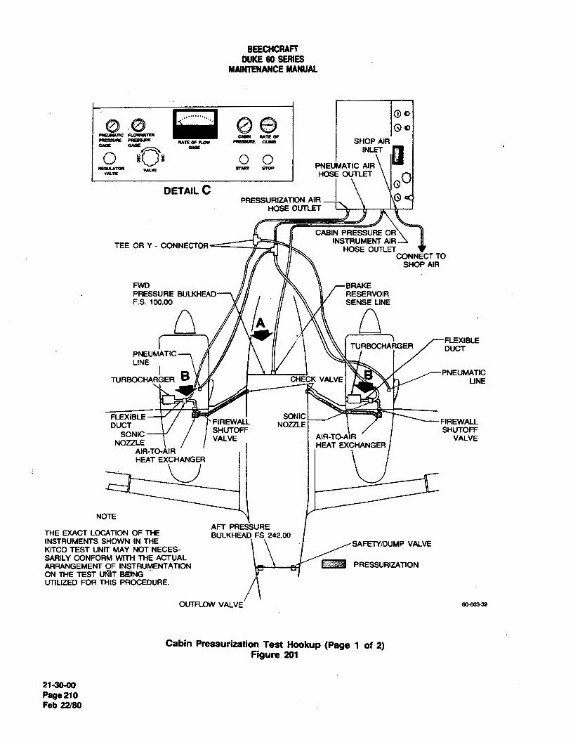
BEECHCRAFTDUKE60 SERIES
MAINTENANCEMANUAL
SHOP AIR
oo INLET
REGUMWR V SURF SmP PNEU WATICAIR-" HOSE OUTŒT O
DETAILCPRESSURIZATION AIR I O <
HOSE OUTLET
CABIN PRESSURE ORINSTRUMENT AIRTEE OR Y - CONNECTOR HOSE OUTLET
CONNECT TOSHOP AIA
FWD BRAKEPRESSURE BULKHEAD RESERVOIRF.S. 100.00 SEN NE
FLEXIBLETURBOCHARGER DUCT
PNEUMATICLINE
PNEUMATICTURBOCHAAGER S CHE K VALVE LINE
FLEXIBLE SONICDUCT FIREWALL NOZZLE FIREWALL
SHUTOFF SHUTOFFSONIC VALVE AIR-TO-AIR VALVENOZZLE HEAT EXCHANGERAIA-TO-AIR
NOTEAFT PRESSURE
THE EXACT LOCATION OF THE BULKHEAD FS 242.00INSTRUMENTS SHOWN IN THE SAFETY/DUMP VALVEKITCOTEST UNIT MAY NOT NECES-SARILY CONFORM WITH THE ACTUALARRANGEMENT OF INSTRUMENTATION PRESSURIZATIONUNIL EED
RUTH
EDURE.
OUTFLOW VALVE 39
Cabin Pressurization Test Hookup (Page 1 of 2)Figure 201
21-30-00Page 210Feb 22/80

BEECHCRAFTDUKE60 SERIES
MAINTENANCEMANUAL
DETAIL A
BRARE RESERVOIRSENSE UNE(FWD PRESSURE BULKHEAD)
DETAIL B0
so-soam
Cabin Pressurization Test Hookup (Page 2 of 2)Figure 202
"END"
21-30-00Page 211
Feb 22/80

BEECHCRAFTDUKE80 SERIES
MAINTENANCEMANUAL
HEATING - DESCRIPTION AND OPERATION
MODE SWITCHThe heater system consists of a 45,000 BTU combustion airheater, (located under the nose baggage compartmentfloor), a six position mode switch, vent air blower,combustion air blower, heater fuel pump, five outlets, anautomatic temperature control and three sensing elements.
In flight, when pressurized, the vent blower obtains airthrough the cabin air check valve, forces it through the eheater and to the cabin outlets. In the unpressurized modein flight and for ground operations, the vent blower obtainsair from the cabin and the ram air plenum chamber and .
forces it through the heater and to the cabin outlets.
On serials P-4 through P-126, except P-123. a vent air tr,distribution bypass valve, located on the forward pressurebulkhead, allows air to be directed into the pilot'scompartment area and is regulated by a control knob onthe pilot's left subpaneL
60-324-1
Exchanging the cabin air is accomplished by exhausting acontrolled amount of air through the isobaric control valve Cabin Temperature Controlson the aft pressure bulkhead. Figure 1
HEATER OPERATIONHEATER CONTROL SYSTEM(Figure 1)
a. To place the heating system in operation select anoperational mode; either MANUAL HEAT or AUTO
The heater controls are located on the copilot's LH HEAT.subpanel. Serials P-4 through P-126, except P-123, b. If the AUTO position is chosen, set the controlincorporates a six-position switch placarded; AUTO H EAT, rheostat for the desired heat. The heater is now set up forMANUAL HEAT, BLOWER, AUTO COOL, MANUAL normal operation providing therrnostatic temperatureCOOL, HI, MANUAL COOL LO, and OFF. On serials regulation.P-123, P-127 and after the mode selector switch differs c. If MANUAL heat control is desired or required byslightly in that a MANUAL. COOL position replaces the a malfunction in the AUTO system, move the switch to theMANUAL COOL Hl and MANUAL COOL LO positions. In MANUAL position. This removes the automatic controlleraddition, two blower positions are placed on the selector and the sensing elements from the control system. Theswitch to allow the blower to be selected without cycling heater will then cycle continuously by the preset integralthrough the opposite mode. The mode switch controls both heater cycling switch.the heating and cooling systems; however, each system d. The CABIN AIR control which regulates theoperates independently of the other. In the manual heat amount of outside ram air to the cabin is located on theposition, the switch bypasses the automatic cabin heat copilot's LH subpanel. Pull the CABIN AIR control fullcontrols and allows maximum heat output. However, the aft for maximum air. The CABIN AIR control isheater output in the manual position is limited by a heater overridden when the cabin is pressurized.cycling switch. In the automatic heat position a e. For windshield defrosting, operate the heater intemperature control rheostat placarded CABIN TEMP either the auto or manual mode and pull out the DEFROSTINCREASE calf be set for the desired cabin temperature. control located on the pilot's LH subpanel.
f. Heated air is normally directed onto the pilot'sOutlet air velocity may be changed in either MANUAL feet. To shut off this air, pull out the PILOT AIR controlHEAT or AUTO HEAT mode by moving the VENT located on the pilot's LH subpanel.BLOWER switch, located in the copilot's LH subpanel to g. The COPILOT AIR control, identical to the P1LOTeither the Hl or LO position. AIR control is located on the copilot's RH subpanel.
21-40-00Page 1
Nov 2/73

BEECHCRAFTDUKE60 SERIES
MAINTENANCEMANUAL
NOTE CAUTION
The volume of air available for the pilot outlet Ma ke certain any malfunction.causing an
and copilot outlet can be divided between the overheat condition is corrected beforetwo outlets as desired by adjusting each control attempting to operate the heater.individually. More heated air will be availablefor defrosting by reducing the flow of air from For additional heat, the PRESSURIZATION AIR TEMIthe pilot and/or copilot outlets. CONTROLS located on the copilot's RH subpanel can b
pulled out to restrict cooling air flow through the cabin aiIf a malfunction resulting in dangerously high temperatures heat intercooler. For maximum heat in the unpressurizel(300°F. to 400°F.) should occur, the heater mode, push the CABIN AIR control full forward tostoiover-temperature switch will lock out and blow either the the flow of incoming cold air.over-temperature fuse (manual mode) or theover-temperature fuse (auto mode) in the heater powercircuit. This renders the heater system, except the blower, NOTEinoperative. The over-temperature fuses are located behindthe LH upper side panel. The heater over-temperature The intercooler doors should be closed during
Iswitch is located on the heater assembly. The switch must all heating operations to reduce the load on thebe manually reset during heater system servicing after an heater. Conversely, the doors should be open toover-temperature condition has occured. reduce load during all cooling operations.
"END"
21-40-00Page 2May 30/75

BEECHCRAFTDUKE60 SERIES
MAINTENANCEMANUAL
HEATING - MAINTENANCE PRACTICES b. Install the clamps at each end of the heater.c. Position the clamp on the heater exhaust shroud
HEA TER REMO VAL located under the heater and secure and safety.d. Install the fuel line to the heater. Slide the boot
The heater should be removed from the aircraft and down the fuel line and secure the clamps around the boot.disassembled. All parts should be thoroughly inspected and e. Install the wire harness to the heater.necessary repairs and parts replacements made every 500 f. Connect the duct to the combustion air blower andhours of operation. secure the clamps.
g. Instalt the nose baggage compartment floorboards.The heater is removed as follows:
COMBUST/ONA/R BLOWER REMOVALa. Remove the necessary nose baggage compartment
floorboards to gain access to the heater. a. Remove the heater.b. Loosen the clamp and disconnect the duct from b. Tag the wires and disconnect the wiring from the
the combustion air blower. combustion air blower and combustion air controtIer.c. Tag the wires and disconnect the wire harness from c. Loosen the clamps and disconnect the ducts on the
the heater. combustion air blower.d. Loosen the clamps around the fuel inlet line boot d. Remove the attaching screws from the combustion
and slide the boot up the fuel line. Disconnect the fuel line air blower and the two controller mounting brackets.from the heater. e. Remove the combustion air blower and controller
e. Remove the safety wire and loosen the clamp on from the aircraft as a unit.the heater exhaust shroud (located under the heater).
f. Remove the clamps, located at each end of the COMBUSTION A/R BLOWER /NSTALLATIONheater.
g. Lift the heater up and out of the aircraft. a. Install the combustion air blower and controller inthe aircraft as a unit.
HEATER INSTALLATION b. Install the two controller mounting brackets andsecure the combustion air blower with the attaching screws.
a. Position the heater in the aircraft taking care to c. Install the ducts on the combustion air blower andguide the fuel drain through the grommet in the skin and secure with the clamps.the exhaust shroud through its opening. d. Install the wiring to the combustion air blower and
HIGH VELOCITYIRLING FLAME
SPARK PLUG COMBUSTION AIRINLET
FUEL INLET
HEATED A
LAELNOID
EXHAUST GASES
GROUND ELECTRODE FRESH AIRWELDED IN COMBUSTION HEAD FROM BLOWER
60.412-1
Aircraft HeaterFigure 201
21-40-00Page 201Nov 2/73

BEECHCRAFTDUKE60 SERIES
MAINTENANCEMANUAL
combustion air controller. VIBRA TOR INSTALLA T/ONe. Install the heater.
a. To install a new vibrator, carefuhy rotate the newHEA TER IGNITION vibrator until the index marks are aligned and the(Figure 201) connector pins on the vibrator can be felt entering the pin
sockets in the vibrator socket, then press the vibrator fullyThe controlled atomized spray from a specially designed and firmly into position.spray nozzle, coupled with high-voltage spark plug ignition, b. Check the heater for operation and close all accessinsures instant firing and continuous burning under all openings.flight conditions. Heat is produced by burning a fuel-airmixture in the combustion chamber of the heater. Aviation INSPECTION AND SER VIC/NG (SPARK PLUG)gasoline is injected into the combustion chamber through (Figure 202)the spray nozzle. The resulting cone-shaped fuel spraymixes with combustion air and is ignited by a spark from If the spark plug appears to be in good condition, exceptthe spark plug. Electric current for ignition is supplied by for a mild coating of oxide on the porcelain and electrodes,an ignition unit which converts 24 volts to a high-voltage, it may be cleaned and reused. Cleaning is accomplished on aoscillating current to provide a continuous spark across the conventional aircraft type spark plug cleaner, except that itspark plug gap. A shielded, high voltage lead connects the will be necessary to use two or more adapters in order toignition assembly to the spark plug. Combustion air enters raise the long extension of the plug far enough out of thethe combustion chamber tangent to its surface and imparts cleaner nozzle opening to provide an effective job. Plug thea whirling or spinning action to the air. This produces a ceramic insert cavity at the terminal end of the plug with awhirling flame that is stable and sustainscombustion under piece of paper or cloth to keep out any of the cleaningthe most adverse conditions because it is whirled around sand. Wipe this cavity out thoroughly with a cloth, wetitself many times. Therefore, ignition is continuous and the with.carbon tetrachloride. If, after cleaning, the spark plugcombustion process is self-piloting. The burning gases travel porcelain is white, and the electrode is not eroded, thethe length of the combustion tube, flow around the outside spark plug gap may be set as follows. Insert a six inch scaleof the inner tube, pass through cross-over passages into an with a sliding clip into the spark plug well until it touchesouter radiating area, then travel the length of this surface the ground electrode welded inside the combustion head.and out the exhaust. Withdraw the scale and note the dimension between the
síîding clip and the end of the scale. Place the scale againstthe bottom of the spark plug gasket and determine the
Ventilating air passes through the heater between the jacket length of the spark plug positive electrode. The differenceand combustion tube assembly duter surface and throughan inner passage in the assembly. Consequently, ventilatingair comes into contact with two or more heated, cylindrical
6 IN<H SCALEsurfaceS• SPARK PLUG WELL
VIBRATOR REMOVALGASKET
a. Remove the necessary access panels, in the nosecompartment, to reach the ignition unit on the heaterassembly.
1
NOTE
Measure the distance the vibrator protrudes out HEATER 3/16 TO 7/32. . COMBUSTION SPARK PLUGof the igmtion assembly to determine when a HEAD GAP
new unit is nserte_dpro.perly.
b. Grasp the vibrator and with a slight back and forthmovement, pull it straight out of the ignition unit. GROUND ELECTRODE
60-153-1
NOTE
For a friction grip, it may be necessary to use apiece of masking or friction tape around the Heater Spark Plug Gapexposed portion of the vibrator. Figure 202
21-40-00Page 202Nov 2/73

BEECHCRAFTDUKE60 SERIES
MAINTENANCEMANUAL
between the two measurements is the spark plug gap. The high-voltage lead temporarily and lay the sparkgap should be 3/16 to 7/32 (0.188 to 0.218) inches. If the plug on the heater jacket.plug gap must be adjusted, the ground electrode may bebent up or down by reaching through the spark plug holewith the appropriate shaped tool. WARNING
Be sure to plug the spark plug hole in the heaterNOTE to prevent any possibility of residual fuel
blowing out and igniting. Do not touch theif the spark plug fails to clean up properly spark plug while energized because ofand/or if the electrode is badly eroded, it dangerously high voltage.should be replaced.
If a new spark plug is being installed, be sure to measure the TEMPERA TURE SENSORS AND CONTROLgap. Do not bend the positive electrode. Torque the spark RHEOSTA T TESTplug to 28 foot-pounds.
NOTENOTE
The aircraft must be in a location, such as aThe spark plug can be checked visually for hangar, where temperatures inside and outsidesparking prior to installing the plug as follows: of the aircraft are equal and stable. WhenDisconnect the wire from the terminal on the making the tests, slight variances may occur;heater wiring side of the terminal strip to however, a defective component will give ade-energize the fuel solenoid valve. Connect the definite indication.
I
700
200
0 10 20 30 40 50 60 70 30 90 100
TEMPERATURE -•Fes.oos.us
Temperature Resistance Curve for Cabin Sensing ElementFigure 203
21-40-00Page 203Nov 2/73

BEECHCRAFTDUKE60 SERIES
MAINTENANCEMANUAL
60
0 40 GO 120 160 200 240 250 320 360 400
TEMPERATUGE-'F
Temperature Resistance Curve for Heater Discharge Sensing ElementFigure 204
a. Using the graph in Figure 203, determine the sensing element and the outside air sensing elementcorrect resistance for the cabin air sensing element. respectively, then add these resistance values. Remove wireDisconnect wire number H78E18 from terminal "S"of the number H73F18 from terminal "8" of the temperaturetemperature control. box terminal strip. Measure the control box terminal strip. Measure the resistance betweenresistance between the terminal on wire number H78E18 the terminal on wire number H73F18 and the terminal onand terminal "6" on the temperature control box terminal wiire H75A18 on terminal "5" of the temperature controlstrip. Disconnect wire number H75B18 from terminal "5" box terminal strip. This resistance should equal the addedof the temperature control box terminal strip. Measure the resistance of the two sensing elements. If not, measure theresistance between the terminal on wire number H75B18 resistance of the two sensing elements. If the resistanceand terminal "10" on the temperature control box terminal does not equal the determined amount, it is defective. Ifstrip. If the measured resistances do not correspond to the the resistance is correct, the heater discharge sensingvalue obtained from the graph, the cabin air sensing element is defective.element is defective. c. Rotate the cabin temperature control to the full
increase position Using the graph in Figure 204, determinethe resistance for heater discharge sensing element.
d. Disconnect wire number H77818 from terminalNOTE "2" of the temperature control box terminal strip. lÝIeasure
the resistance between the terminal on wire H77818 andDo not reinstall the disconnected wires on the terminal "1" of the temperature control box terminal strip.terminal strip until all tests are complete. If the resistance does not equal the determined value, the
heater discharge sensing element is defective.e. With the test probes still attached as noted in step
b. Using the graphs in Figures 204 and 205, "d", rotate the cabin temperature control to the fulldetermine the correct resistance for the heater discharge decrease position.
21-40410Page 204Nov 2/73
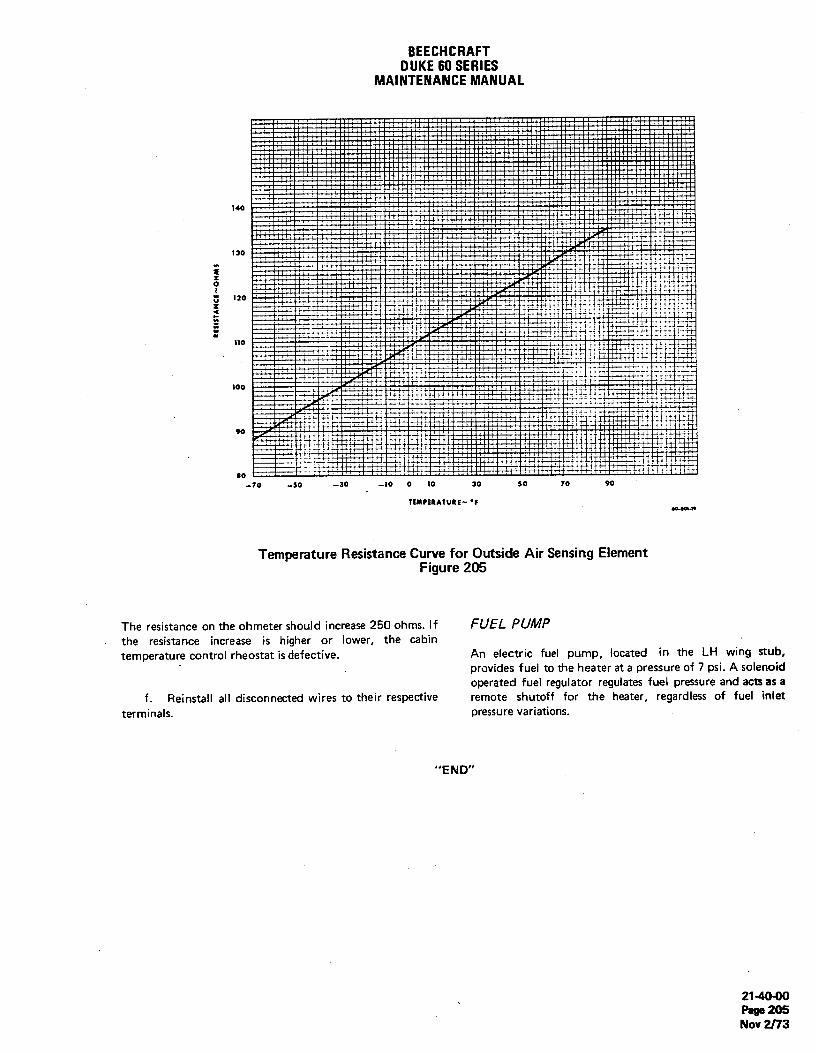
BEECHCHAFTDUKE60 SERIES
MAINTENANCEMANUAL
140
130
110
80-70 -50 -30 -10 0 10 30 50 10 90
TEMPERATURE~ 'Feo-eet.to
Temperature Resistance Curve for Outside Air Sensing ElementFigure 205
The resistance on the ohmeter should increase 250 ohms. If FUEL PUMPthe resistance increase is higher or lower, the cabintemperature control rheostat is defective. An electric fuel pump, located in the LH wing stub,
provides fuel to the heater at a pressure of 7 psi. A solenoidoperated fuel regulator regulates fuel pressure and acts as a
f. Reinstall all disconnected wires to their respective remote shutoff for the heater, regardless of fuel intetterminals. pressure variations.
"END"
21-40-00Page 205Nov 2f/3

BEECHCRAFTDUKE60 SERIES
MAINTENANCEMANUAL
COOLING - DESCRIPTION AND OPERATION temperature gas. This gas passes through the condenserwhere cooling air removes heat from the gas, condensing it
The optional air conditioning system is a recirculating air to a liquid state. The liquid is then stored in thecooling system containing a 16,000 BTU refrigerative type receiver-dryer where any moisture or foreign material iscooler. The unit is controlled by an automatic temperature removed from the system. The refrigerant flows to thecontrol and three sensing elements. expansion valve where it is metered into the evaporator at a
rate which allows all the liquid to return to a gas. The heatA six position mode switch controls the heater and air required for evaporation is absorbed from the cabin airconditioner systems: however, each system operates passing over the evaporator coils. After passing through theindependently of the other. When placed in AUTO evaporator, the refrigerant returns to the compressor at aposition, the temperature is automatically controlled reduced pressure. For partial cooling, a hot gas bypass valvethrough the temperature controller located on the forward allows a portion of the gas to bleed off from the condenser,pressure bulkhead above the pilot pedals. It also regulates cycling back through the compressor,the cabin temperature variations monitored at the sensingunits. The sensing units are located in the ram air inlet,heater outlet duct and forward of the two pressure control NOTEvalves on the rear pressure bulkhead. When placed in theMANUAL COOL HI position, the switch bypasses the Beginning with airplane serials P-123, P-127 andautomatic controls and allows maximum air conditioning after, and prior airplane's having installed Kitoutput. The maximum output is limited by an evaporator Number 60-5006, the hot gas bypass valve, linethermal switch and an overpressure switch. The MANUAL and suction accumulator were removed fromCOOL LO position allows a hot-gas bypass valve (if the system.installed) to be cycled on and off by a timer. The bypassvalve regulates the flow of refrigerant to the condenser An overpressure switch and a pressure relief valve areallowingpartialcoolingofthecabin. incorporated into the system to regulate system
(compressor discharge) pressure. The overpressure switch isOn serials P-123, P-127 and after, a MANUAL COOL located in the condenser compartment of the right nacelleposition replaced the MANUAL COOL HI and LO positions and is set to actuate at 375 ± 10 psi. When this switch ison the mode selector switch. Two BLOWER positions are actuated, power is removed from the compressor magneticplaced on the mode switch to allow the blower to be clutch and the 3 amp fuse is shorted through a resistor toselected without cycling through the opposite mode. ground. A pressure relief valve, located on the compressor
discharge line immediately before it enters the condenser, isThe air scoop and ramp assembly located in the upper RH set to bleed off pressure at 450 psi.nacelle controls the air circulation through the condensercompartment and is completely automatic. The air scoop On airplane serials, P-275 and after, and on those priorand ramp assembly has three positions, "closed" (when the airplanes which have complied with Service Instructionsair conditioning is not in use), "flight" (air scoop extended 0599-427, a low pressure switch is installed on theabout 2 inches above the nacelle), and "ground" (air scoop evaporator. This switch is designed to actuate when thefully extended). When the air conditioning is turned on, a refrigerant pressure drops to 7 ± 1 psi. The actuation of theswitch incorporated on the landing gear selects air scoop low pressure switch shorts the 3 ampere fuse to the airplaneposition; gear down, the air scoop will open to the structure through the resistor located near the evaporator."ground" position; gear off the ground, the air scoop will The fuse, located in the right nacelle, is thus opened,open or lower to the "flight" position. The condenser fan, preventing further operation of the compressor magneticwhich is wired in circuit with the landing gear safety switch, clutch and the compressor until the air conditioner systemoperates only when the air conditioning mode is selected has been serviced.and the air;5fanè n on the ground.
NOTEREFR/GERATIVE AIR COOLING SYSTEM
The low pressure switch which was originallyThe air conditioning system is similar to many home and installed on airplane serials P-275 throughautomotive units and consists of six major components. P-292 and P-294, prior to compliance withThe belt-driven compressor, which is coupied by a magnetic Service instructions 0599-427, actuated at aclutch, compresses the refrigerant to a high pressure, high pressure of 18 ± 2 psi.
"END"
21-50-00Page 1
May 30/75

BEECHCRAFTDUKE 60 SERIES
MAINTENANCEMANUAL
COOLING - MAINTENANCE PRACTICES be observed for bubbles or a milky appearance caused by aninsufficient refrigerant level.
Servicing' the air conditioning system consists ofperiodically checking the refrigerant level, checking If it is necessary to add refrigerant to a partially chargedcompressor oil level and changing the system air filter, system, add refrigerant slowly until a satisfactory conditionRecharge the system whenever the refrigerant level is low, is observed through the sight glass, then add an additionalair has entered the system or components carrying 1/4 to 1/2 pound of refrigerant.refrigerant are replaced. Refrigerant leaks may be detectedby inspection with flameless teak detector.
NOTEThe refrigerant level may be observed through the sightglass located in the RH wheel well (P-4 through P-144) or After the system has been charged theby removing a plug button from the forward section compressor oil level should be checked asfloorboard forward of the copilot's seat (P-145 and after). outlined under CHECKING COMPRESSOR
OIL LEVEL.CHARGING THE A/R CONDITIONING SYSTEM
A/R CONDITION/NG FUNCTIONAL TESTWhen working on a refrigerative air cooling system, observethe following special servicing precautions: With the compressor running at 1,100 rpm a functional
check may be made in accordance with Chart 201. Chargea. Remember, this is a high pressure system. When the system as outilned in CHARGING THE AIR
disconnecting a line, loosen the fittings just enough to bleed CONDITIONING SYSTEM.off pressure slowly, then disconnect the fitting.
b. Whenever a line is disconnected, purge the entiresystem with a vacuum pump operating at the 125 micron CHECKING COMPRESSOR O/L LEVELlevel. (Figure 201)
c. Use only refrigerant (17, Chart 207, 91-00-00);other refrigerants, particularly those containing methyl The compressor oil level should be checked by a qualifiedchloride, will cause rapid deterioration of the aluminum air conditioner man at the following times:compressor components.
d. When servicing the system with refrigerant, avoid a. After the air conditioner has operated for the firstsmoking or working near an open flame. Refrigerant passing time.over an open flame will produce a highly toxic phosgene b. At the beginning of each season's operation.gas. c. When oil is emitted from the compressor during
servicing operation.Hook the service unit to the connections on the d. After the air conditioning system has beencompressor. The abbreviation DISCH or the letter "D" on recharged.the compressor cylinder head designates the discharge e. If a component is replaced.service valve. The word SUCTION or the letter "S" on thecompressor cylinder designates the suction service valve. The compressor is serviced with oil (18, Chart 207,
91-00-00). Only these or equivalent oils should be usedWhen charging a completely purged system, charge with 5 when adding oil. To check the compressor oil level, use thepounds of refrigerant. After charging, the sight glass should following procedure:
CHART 201AIR CONDITIONING FUNCTIONAL TEST
TEMPERATURE °F COMPRESSOR PRESSURE (PSI)AMBlENT (OAT) PLENUM (MAX)* SUCTION DISCHARGE
60 45 15-20 120-17070 49 15-22 140-20080 54 15 - 25 165 - 23090 59 18 - 30 185 - 260
100 64 20 - 35 205 - 290110 69 22 -40 230 - 320
*Measure temperature at outlet nearest plenum 21-50-00Page 201Nov 2/73

BEECHCRAFTDUKE 60 SERIES
MAINTENANCEMANUAL
FINGER RING
108°
siA -OIL CHECK PLUG(ALSO OTHER SIDE)
60-451-1A
NOTCHES1/10 IN. APART
Dipstick and Compressor Oil Check PlugFigure 201
a. Operate the air conditioner for approximately 15 CHART 202minutes in which the last 5 minutes should be at low engine CHECKING COMPRESSOR OIL LEVELrpm (1,000 to 1,100).This allows the oil to accumulate inthe compressor for an accurate oil level reading. Dip Stick Oil to
b. Attach service gages to compressor service valve Depth (In.) be Added (Oz.)ports. .6 8.0
c. With air conditioner operating, slowly close the .8 6.5suction service valve until the suction pressure gage reads O 1.0 5.0or slightly below. 1.2 3.0
d. Stop the air conditioner and quickly close the 1.4 1.5 isuction service valve when the suction gage reads a littleabove zero. Oil should be removed when depths greater than 1.8 inch
e. Close the discharge service valve, are observed.f. With both service valves closed, the suction
pressure will slowly rise to about five pounds gage pressure. Compressor oil level reduces .4 to .T inches duringg. The remaining pressure is relieved by unscrewing operation at maximum rpm and also drops slightly with
the plug for 5 full turns and bled to zero pressure. reduced evaporator loads. Approximately 7 oz. of oil ish. Remove the oil plug and O-ring. required to initially wet the system and circulate with thei. To place the crank throw in the best position for refrigerant. When an evaporator or condenser coil is
dip stick insertion, point the keyway on the compressor changed, add approximately 2 oz. of oil on installation,shaft up toward the cylinder head. then check and adjust the oil level as recommended. A
j. Insert an oil dipstick until the end contacts the locally manufactured dip stick (see Figure 201) may bebottom of the trankeese. Remove and measure the oil fabricated from 1/8 inch diameter rod; a nonferrousdepth. material, which is not subject to corrosion, is preferred.
Notches cut 1/10 inch apart will aid in visually detecting oildepth.
NOTE k. Install the oil plug and O-ring and check for leaksusing a flameless leak detector.
A compressor oil level depth of 1.5 to 1.8 I. Unseat both the suction service valve and theinches is satisfactory. If the oil level is below discharge service valve and turn to the full aft position.1.5 inches, add oil (18, Chart 207, 91-00-00), m. Remove the service gages and install the caps onthen remeasure. the service ports.
21-50-00Page 202Nov 2/73

BEECHCRAFTDUKE60SERIES
MAINTENANCEMANUAL
n. The aircraft may now be returned to service. R/GGING THE AIR SCOOP(Figure 202)
EVAPORATOR AIR FILTER REPLACEMENTTwo limit switches control the air scoop actuator travel for
The evaporator air filter should normally be replaced the flight and ground positions. The extend limit switchannually. Actual replacement may be required more often limits the air scoop travel from the closed position to thedue to extremely dusty operating conditions. flight position. The retract switch limits the air scoop travel
from the ground position to the flight position. The aira. Remove the necessary equipment in the nose scoop and limit switches may be adjusted as follows:
compartment to gain access to the floorboards forward of a. Disconnect the air scoop actuator rod end bythe pressure bulkhead. removing the attaching bolt and nut.
b. Remove the screws securing the top of the b. With power on, run the actuator in to its internalevaporator filter access plate. limit and loosen the rod end check nut.
c. Cut the cord securing the filter to the evaporator c. With the air scoop faired to the nacelle adjust theplumbing. rod end to the attaching bolt but do not secure the actuator
d. Remove the old filter. to the air scoop at this time. Tighten the rod end check nut.e. When installing the new filter, be sure the d. Manually raise the air scoop 1.9 inches above the
reinforced backing of the filter is placed against the top of the nacelle and hold this position while adjusting theevaporator coil, switches.
AIR SCOOP FLIGHT POSITION
GROUND POSITION
1.91NCHES t' N'
AIR SCOOP ACTUATOR
RETRACT LIMIT SWITCH(EXTEND SWITCH ONOPPOSITEC
ENSER
AIR PRESSURE , •, •
RELIEF DOOR ¡ .
"CONDENSER BLOWER
60-426-tA
Air ScoopFigure 202
21-50-00Page 203Nov 2fl3

BEECHCRAFTDUKE60SERIES
MAINTENANCEMANUAL
e. Loosen the attaching screws and move the switches the terminals on the blower.in their slotted mounts until they actuate (a distinct click is e. Position the air ramp to align the air ramp hingesaudible) in the following order: the extend switch actuates and install the hinge pins.first when the air scoop moves up from the closed position; f. Position the air scoop and ramp vertically to installthe retract switch actuates first when the air scoop moves the skin covering the condenser compartment.down from the ground position. Secure with the attaching g. Secure the skin with attaching screws.screws.
f. Because the ground position is automatically COMPRESSOR BEL T TENS/ON AD.JUSTMEN7achieved by the internal limits of the actuator noadjustment is needed. After 36 to 48 hours operating time, a new belt will stretch
g. Install the actuator rod end to the attaching bolt to its normal operating length. The belt tension should beand securethe nut, checked at this time and adjusted (by moving the
h. Check for proper operation. compressor up and down in its slotted mounts) so that abelt tension gage, placed at a point midway between the
CONDENSER BLOWER REMOVAL longest span will register a tension of 100 to 105 poundsAfter adjusting the tension on a new belt, be sure the beh
The condenser compartment is located aft of the right has ample clearance on all sides.nacelle firewall.
COMPRESSOR BELT REMOVALa. Remove the screws securing the skin covering the
condenser compartment. Position the air scoop and ramp a. Remove the RH engine cowling to gain access tcvertically to remove the skin. the compressor belt.
b. Remove the pins at the air ramp hinge points and b. Loosen compressor attaching nuts and slide thelift the air ramp out. compressor upward in its slotted mount to relieve tensior
c. Disconnect the electrical wiring at the terminals on on the belt. Roll the belt off the compressor pulley.the condenser blower. Remove the screws securing the c. Remove the bolts a tt a ch i ng t heblower to its mounting bracket and then lift out the compressor/turbocharger mount support to the engine.blower. d. Remove the belt from the engine crankshaft pulley
d. Remove the screws securing the blower mount and slip it out between the compressor/turbocharger moun1bracket and the two baffles to the condenser compartment. and the engine.Lift out the mounting bracket and baffles.
e. Disconnect the fittings on the condenser and cap. COMPRESSOR BELTINSTALLATION
a. Slip the compressor belt between theWARNING compressor/turbocharger mount and the engine and
position the belt on the crankshaft pulley.The lines connected to the condenser are under b. Secure the compressor/turbocharger mounihigh pressure. Refer to CHARGING THE AIR support to the engine with attaching screws.CONDITIONING SYSTEM, in this chapter c. Roll the belt onto the compressor pulley. Slide thebefore disconnecting any fitting in the compressor downward in its slotted mount to apply tensiorrefrigerant system. on the belt and secure the compressor attaching nuts.
d. Install the RH engine cowling.
f. Remove the screws securing the condenser to its COMPRESSOR REMOVALmounting flange and lift the condenser out of thecompartment. a. Remove the RH engine cowling to gain access to
the air conditioner compressor.CONDENSER BLOWER INSTALLATION b. Disconnect electrical leads to the magnetic clutch.
c. Disconnect refrigerant lines at compressor servicea. Position condenser in condenser compartment and valves.
secure with attaching screws.b. Remove cap and install the fittings to the WARNING
condenser.c. Position the two baffles to the condenser The lines connected to the compressor are
compartment and the blower mount bracket and secure under high pressure. Refer to CHARGlNG THEwith attaching screws. Al R CO NDt TIO NtNG SYSTEM, in this
d. Position the blower to its mounting bracket and chapter before disconnecting any fitting in thesecure with attaching screws. Attach the electrical wiring at refrigerant system.
21-50-00
Page 204Nov 2/73

BEECHCRAFTDUKE60 SERIES
MAINTENANCEMANUAL
d. Loosen the compressor mounting nuts. brackets. Position washers on the compressor studs ande. Slide the compressor up in its slotted mounting to loosely install the attaching nuts,
relieve tension on the drive belt. Rolf belt off the b. Roll the compressor drive belt onto the compressorcompressor pulley, pulley. For adjustment of the belt refer to COMPRESSOR
f. Remove mounting nuts and washers and remove BELT TENSION ADJUSTMENT.compressor. c. Torque the compressor mounting nuts to 160-190
inch-pounds.d. Install the refrigerant lines to the compressor
COMPRESSOR INSTALLATION service valves.e. Install the electrical leads to the magnetic clutch,
a. Position the compressor in its slotted mounting f. Install the RH engine cowling.
"END"
21-50-00Page 205Nov 2/73

BEECHCRAFTDUKE60 SERIES
MAINTENANCEMANUAL
CHAPTER 22
L/ST OF PAGE EFFECT/VITY
CHAPTERSECTIONSUBJECT PAGE DATE
22-EFFECTIVITY/CONTENTS 1 Oct 27/75
22-10-00 1 Oct 27/75201 Oct 27/75
22-11-00 1 Oct 27/752 Oct 27/75
101 Oct 27/75102 Oct 27/75103 Oct 27/75104 Oct 27/75105 Oct 27/75106 Oct 27/75201 Oct 27/75
CHAPTER 22 - AUTO FLIGHT
TABLE OF CONTENTS
CHAPTERSECTION
SUBJECT SUBJECT PAGE
GENERAL 22-10-00 1Description and Operation 1
H-14 Autopilot 1Maintenance Practices 201
H-14 Autopilot 201
GENERAL 22-11-00 1Description and Operation 1
New-Matic Autopilot 1Troubleshooting 101Maintenance Practices 201
New-MaScAutopilot 201
"END"
22-EFFECTIVITY/CONTENTSPage 1
Oct 27/75

BEECHCRAFTDUKE60 SERIES
MAINTENANCEMANUAL
GENERAL - DESCRIPTION AND OPERATION through the autopilot control valves.
Servo actuators, powered by air pressure move the aircraftH-14 AUTOPILOT control surfaces. The autopilot may be turned on anytime
after the aircraft engines have been started. Because theequipment is transistorized, no warmop tinie is required;
The primary components of the autopilot pneumatic however, make certain that the gyros are erect and stablesystem are shown in Figures 202 and 204 in Chapter prior to engaging the system. Electrical power to the36-00-00. Air pressure picked up from the pressure autopilot is interrupted by pulling the autopilot circuitmanifold is admitted to the autopilot pneumatic system breaker.
"END"
22-10-00Page 1
Oct 27/75

BEECHCRAFTDUKE60SERIES
MAINTENANCEMANUAL
GENERAL - MAINTENANCE PRACTICES removable panel on the left underside of the fuselageimmediately aft of the rear pressure bulkhead.
H-14 AUTOP/LOT
For maintenance, repair, troubleshooting and testing refer Adjustment of the pneumatic pressure system is performedto the procedures described in the BEECHCRAFT H-14 by adjusting the various regulators in a specified sequence.Autopilot Maintenance Manual (P/N 130333F) and the A PRESSURIZATION SYSTEM ADJUSTMENT CHARTMaintenance Manual Supplement (P/N 98-30603). corresponding to applicable illustrations and a general
adjustment procedure for each individual regulator areAccess for adjustment of the autopilot is through a provided in Chapter 36-00-00.
"END"
22-10-00Page 201
Oct 27/75
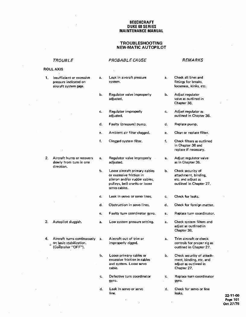
BEECHCRAFTDUKE60SERIES
MAINTENANCEMANUAL
TROUBLESHOOTINGNEW-MATIC AUTOPlLOT
TROUBLE PROBABLE CAUSE REMARKS
ROLL AXIS
1. Insufficient or excessive a. Leak in aircraft pressure a. Check all lines andpressure indicated on system. fittings for breaks,aircraft system gage. looseness, kinks, etc.
b. Regulator valve improperly b. Adjust regulatoradjusted. valve as outlined in
Chapter 36.
c. Regulator improperly c. Adjust regulator asadjusted. outlined in Chapter 36.
d. Faulty (pressure) pump. d. Replace pump.
e. Ambient air filter clogged. e. Clean or replace filter.
f. Clogged system filter. f. Check filters as outlinedin Chapter 36 andreplace if necessary.
2. Aircraft hunts or recovers a. Regulator valve improperly a. Adjust regulator valveslowly from turn in one adjusted. as in Chapter 36.direction.
b. Loose aircraft primary cables b. Check security ofor excessive friction in attachment, binding,aileron and/or rudder cables, etc. and adjust aspulleys, bell cranks or loose outlined in Chapter 27.servo cables.
c. Leak in servo or servo lines. c. Check for leaks.
d. Obstruction in servo lines. d. Check for foreign matter.
e. Faulty turn coordinator gyro. e. Replace turn coordinator.
3. Autopilot sluggish. a. Low system pressure setting. a. Check system filters andadjust as outlined inChapter 36.
4. Aircraft turns continuously a. Aircraft out of trim or a. Trim aircraft or checkon basic stabilization. improperly rigged. controls for proper rig as(Coiltroller "OFF"). outlined in Chapter 27.
b. Loose primary cables or b. Check security of attach-excessive friction in cables ment, binding, etc, andand system. Loose servo adjust as outlined incable. Chapter 27.
c. Defective turn coordinator c. Replace turn coordinatorgyro. gyro.
d. Leak in servo or servo d. Check for servo or lineline. leaks. 22-11-00
Page 101Oct 27/75

BEECHCRAFTDUKE60 SERIES
MAINTENANCEMANUAL
TROUBLESHOOTINGNEW-MATIC AUTOPILOT (Cont'd)
TROUBLE PROBABLE CAUSE REMARKS
ROLL AXIS (Cont'd)
5. Aircraft rate of turn a. Improper regulator a. Adjust regulator as outlinedtoo fast or too slow. adjustment. in Chapter 36.
b. Turn coordinator faulty. b. Replace turn coordinator.
6. Continuous control wheel a. Turn coordinator faulty. a. Replace turn coordinator.oscillation in smoothair. b. Improper gyro speed or b. Adjust system pressure as
excessive pressure in outlined in Chapter 36.system.
7. No turns or turns in one a. Faulty turn coordinator. a. Replace tum coordinator.direction only, in responseto turn control or on all b. Faulty controller/amplifier. b. Replace controller/amplifier.modes of navigationcoupler operation.
8. Aircraft rolls in one a. Servos improperly phased. a. See System Block Diagram,direction only either • Figure 2.
.Ieft or right.
b. Turn coordinator not b. Plumb per System Blockplumbed properly. Diagram, Figure 2.
9. Aircraft turns in the a. Nav input signal reversed. a. Reverse connectors to VOR.wrong direction in"CAP"and "TRK"modes.
10. No aircraft response from a. Faulty turn coordinator a. Replace turn coordinator.navigation coupler in any gyro.mode, ground check showselectrical. b. Obstruction in pressure lines. b. Check for foreign matter.
11. Aircraft fails to turn a. Faulty magnetic heading a. Replace magnetic headingto and hold magnetic sensor. sensor.headings.
b. Faulty heading selector b. Replace controller/amplifier.resolver.
c. Faulty controller/amplifier. c. Replace controller/amplifier.
12. Magnetic heading con- a. Heading sensor misaligned in a. Check for proper installation.sistently higior toi. aircraft.
b. Heading azimuth dial shifted b. Tighten screw and re-on shaft. calibrate,
c. Improper adjustment of c. Calibrate for the magneticcontroller/amplifier. cardinal points.
13. Cardinal headings in- a. Controller/amplifier im- a. Calibrate for the magneticaccurate. properly adjusted. cardinal points.
22-11-00Page 102Oct 27/75

BEECHCRAFTDUKE60 SERIES
MAINTENANCEMANUAL
TROUBLESHOOTINGNEW-MATICAUTOPILOT (Cont'd)
TROUBLE PROBABLE CAUSE REMARKS
ROLL AXIS (Cont'd)
13. Cardinal headings in- b. Leak in servo system. b. Check for leaks.accurate.(Cont'd)
c. Low primary pressure. c. Adjust system as outlinedin Chapter 36.
14. Cardinal headings accurate a. Faulty heading sensor. a. Replace the heading sensor.but intermediateheadings inaccurate. b. Faulty controller/amplifier. b. Replace controller/amplifier.
15. Insufficient or no control a. Faulty controller/amplifier. a. Replace controller/amplifier.in "CAP" and "TRK"modes. b. Faulty omni converter. b. Replace omni converter.
c. insufficient signal from c. Repair or replace omniomni. indicator.
d. "NAV SENS" improperly d. Readjust.adjusted. °
16. Localizer approach is a. "LOC GAIN" is set high or low. a. Adjust.either sluggish or toosensitive.
17. No electrical output left a. No A+ input or improperly a. Check A+ and ground.or right on controller/ grounded.amplifier test jacks.
b. Defective controller/ b. Replace controller/amplifier or power supply. amplifier or power
supply.
18. Output only one way on a. Defective controller/ a. Replace controller/controller/amplifier test amplifier. amplifier.jacks.
19. No output on HDG mode a. Defective controller/ a. Replace controller/on controller/amplifier amplifier, or harness, or amplifier; or harness, ortest jacks. heading sensor. heading sensor.
20. Heading output on two a. Defective sensor; or a. Replace heading sensor,reciprocal headings, but harness; or faulty or check harness. Replace
.not-o.g the other two. controller/amplifier. controller/amplifier.
21. "O" output when in a. Defective nav switching a. Check nav input leads.CAP, TRK, or APP console;or no nav informa- Replace controller/amplifier.mode, with nav signal. tion; or defective
controller/amplifier.
22. Output voltage in CAP a. Wrong nav input signals. a. Check wiring,mode decays to "O"voltage. b. Defective switching console b. Repair or replace console.
(if installed).22-11-00Page 103
Oct 27/75

BEECHCRAFTDUKE60 SERIES
MAINTENANCEMANUAL
TROUBLESHOOTINGNEW-MATIC AUTOPILOT (Cont'd)
TROUBLE PROBABLE CAUSE REMARKS
ROLL AXIS (Cont'd)
22. Output voltage in CAP c. Dirty input signal (AC c. Check indicators.mode decays to "O" volts).voltage. (Cont'd)
23. Voltage output in MAN, a. Polarization pins reversed a. Reverse pins. See SystemCAP, TRK, and APP mode on heading sensor plug. Block Diagram, Figurebut none in HDG mode. 2.
24. Nav indicator needle a. One of the components is a. Check for shorts.deflects left or right shorted to ground,when controller/amplifieror radio is turned on.
25. Low or high intercept a. Incorrect setting on a. Adjust intercept angle.angle. controller/amplifier.
b. Low or high voltage output b. Check nav indicators toon nav indicators. manufacturer's specs.
PITCH AXIS
1. Pitch channel will not a. Defective pitch/altitude a. Check on Test Set TS-108center up electrically. sensor or amplifier. or replace one at a time.
2. Altitude channel will not a. Defective pitch/altitude a. Check on Test Set TS-108center up electrically. sensor or amplifier. or replace one at a time.
3. Altitude hold solenoid a. Pressure switch on servo a. Check for faulty switch andvalve will not actuate. control valve out of circuit. replace if necessary,
b. Defective solenoid valve. b. Replace solenoid valve.
c. Defective altitude switch c. Check continuity. Seeon controller/amplifier. System Block Diagram,
Figure 2.
4. Servo control valve a. Improper pressure ad- a. Adjust pressure as outlinedwill not center, justment. in Chapter 36.
b. Sticky valve. b. Replace valve.
5. Output voltageis¯
a. Pitch/altitude amplifier a. See System Blockinadequate. sensor or harness shorted Diagram, Figure 2,
or improperly wired. run check for shorts.
6. Pressure switch will not a. Defective pressure switch a. Replace pressure switch.make contact when or not set at properpressure is on. pressure.
7. Output voltage one way a. Servo control valve shorted a. Replace valve.only on pitch and to ground.altitude channels.
22-11-00Page 104Oct 27/75

BEECHCRAFTDUKE60 SERIES
MAlNTENANCEMANUAL
TROUBLESHOOTINGNEW-MATIC AUTOPILOT (Cont'd)
TROUBLE PROBABLE CAUSE REMARKS
PITCH AXIS (Cont'd)
8. System will not maintain a. Servo control valve not a. Disconnect electrical power.trimmed configuration pneumatically centered. Center valve pneumaticallyeven though centered by use of differential gageelectrically. to ±
.04 in Hg.
b. Leak in servos or improperly b. Check for leaks and rig.rigged.
c. Leak in pitch/altitude c. Replace sensor.sensor.
9. System will not respond to a. Primary vacuum (pressure) a. Adjust pressure as outlinedairspeed changes. not set properly. in Chapter 36.
b. Pitot pressure inadequate. b. Check pitot plumbing.
c. Decay rate improperly c. Adjust as required.adjusted.
10. System will not respond a. Defective pitch/altitude a. Replace pitch/altitudeto up command adjust- amplifier. amplifier.ment.
b. No EVT potentiometer. b. Replace turn coordinator.
11. System will not respond a. Pitch/altitude amplifier a. Adjust as required.to altitude gain adjust- limiter improperly set.ment.
12. Aircraft has long term a. Decay rate improperly a. Adjust as required.oscillation about pitch adjusted.axis with altitude holdOFF. b. Pitch altitude gain improperly b. Adjust as required.
adjusted.
c. Friction in elevator or servo c. Check for friction andsystem. . correct.
13. Aircraft has short term a. Decay rate too tight. a. Adjust as required.oscillation about pitchaxis. b. Pitch gain too high. b. Adjust as required.
c. Primary pressure too high, c. Readjust pressure as outlinedin Chapter 36.
14. Aircraft oscillates with a. Altitude gain too high. a. Adjust as requiredaltitude hold ON.
b. Decay rate improperly b. Adjust as required.adjusted.
15. Aircraft does not return a. Altitude hold solenoid a. Replace solenoid.to altitude when displaced. inoperative.
22-11-00Page 105
Oct 27/75

BEECHCRAFTDUKE60 SERIES
MAINTENANCEMANUAL
TROUBLESHOOTINGNEW-MATIC AUTOPILOT (Cont'd)
TROUBl.E PROBABLE CAUSE REMARKS
PITCH AXIS (Cont'd)
15. Aircraft does not return b. Leak in altitude system. b. Check for leaks.to altitude when dis-placed. (Cont'd) c. Altitude limiter improperty c. Adjust as required.
adjusted.
16. Aircraft descends or a. Servo control valve not a. Apply positive 6.0 voltsascends continually when phased correctly. - (max) to blue lead andsystem engaged. verify nose up response.
"END"
22-11-00Page 106
oct27/75

BEECHCRAFTDUKE 60SERIES
MAINTENANCEMANUAL
GENERAL - MAINTENANCE PRACTICES to the procedures described in the BEECHCRAFTNew-Matic Autopilot 8-8 Ground and Flight Check
NEW-MAT/CAUTOP/LOT Procedures Manual (P/N 3957).
For maintenance, repair, troubleshooting and testing refer
"END"
22-11-00Page 201
Oct 27/15

BEECHCRAFTDUKE60 SERIES
MAINTENANCEMANUAL
CHAPTER 23
LIST OF PAGE EFFECTIVITY
CHAPTERSECTIONSUBJECT PAGE DATE
23-EFFECTIVITYlCONTENTS 1 Jun 13/84
23-60-00 1 Jun 13/84201 Jun 13/84202 Jun 13/84
CHAPTER 23 - COMMUNICATIONS
TABLE OF CONTENTS
CHAPTERSECTION
SUBJECT SUBJECT PAGE
STATIC DISCHARGING 23-60-00Description and Operation 1Maintenance Practices 201
Static Wick Removal (Prior to P-581) 201Static Wick Installation (Prior to P-581) 201Static Wick Removal (P-581 and after) 201Static Wick Installation (P-581 and after) 201
"END"
23-EFFECTIVITYlCONTENTSPage 1
A15 Jun 13/84

BEECHCRAFTDUKE60 SERIES
MAINTENANCEMANUAL
STATIC DISCHARGING - DESCRIPTION AND Therefore, static wicks are installed on the trailing edges ofOPERATION the flight surfaces and wing tips to aid in the dissipation of
the electrical charge. Prior to serial P-581 two static wicksA static electrical charge may build up in the surface of the are installed on each wing tip, two on each elevator, andairplane while it is in flight. This electrical charge, if retained, two on the rudder. At serial P-581 and after three staticcan cause interference in radio and avionics equipment wicks are installed on each wing tip, three on each elevator,operation. It is also dangerous to personnel disembarking and three on the rudder.after landing and to personnel servicing the airplane.
"END"
23-60-00Page 1
A15 Jun 13/84

BEECHCRAFTDUKE60 SERIES
MAINTENANCEMANUAL
STATIC DISCHARGING - MAINTENANCE NOTEPRACTICES
Acceptable substitutes for the preceding may be
IPrior to serial P-581 static wicks, two on each wing tip, two used in accordance with MIL-B-5087B or theon each.elevator, and two on the rudder, are bolted to the surface may be prepared in accordance withflight surfaces. Each of these ten static wicks are removed MIL-M-3171C.and installed in the same manner. Starting at serial P-581and after, there are three static wicks on each wing tip, each NOTEelevator, and the rudder. These fifteen static wicks arescrewed into their bases which are riveted to the flight Dissimilar materials are not to be used insurfaces. These bases should not need to be removed in intimate contact unless suitably protectednormal service. against electrolylic corrosion. Whenever it is
necessary that any combination of such metalsbe assembled, an interposing material
STATIC WICK REMOVAL (Prior to P-581) compatible to each should be used.
a. Remove the two screws and lock washerssecuring the wick to the surface. b. Install the wick, using the two screws and lock
b. Remove the wick from the surface. washers.c. Refinish the surface area around the wick
attachment point with the original finish or a clear laquerconforming to MIL-L-6806.
I STATIC WICK INSTALLATION (Prior to P-581)STATIC WICK REMOVAL (P-581 and after)
a. Unscrew the static wick from the base.Clean around the static wick area by: b. Remove the static wick and lock washer.
a. Removing all anodic film, grease, oil, paints, STATIC WICK INSTALLATION (P-581 and after)lacquer, rnetal finishes or other high resistance propertieswith Minnesota 3M No. 600 grit sandpaper, or equivalent, The threads must be clean and free of grease, oil and paint.and solvent (41, Chart 201, 91-00-00). The mating surfacesmust be smooth and contoured so that maximum surface a. Install the static wick and lock washer.area is in actual contact. b. Torque the static wick to 4.7 inch-pounds.
23-6040Page 201
A15 Jun 13/84

BEECHCRAFTDUKE60 SERIES
MA1NTENANCEMANUAL
DETAIL
DETAIL A
DETAIL NOTEThe static wick installation shown is for airplanes prior to P-581 with static wicks installed in groups of two (ten perairplane). On later serials the static wicks are installed in the
187 same general location, in groups of three (fifteen perairplane). Detail "A" is only for the earlier installation.
2 2
3
1
A B60 353 2
DETAIL
Static WicksFigure201
"END"
23-60-00Page 202Jun 13/84 A15

BEECHCRAFTDUKE60SERIES
MAINTENANCEMANUAL
CHAPTER 24
LIST OF PAGE EFFECTIVITY
CHAPTERSECTIONSUBJECT PAGE DATE
24-EFFECTIVITY 1 May 12/78
24-CONTENTS 1 May 12/782 May 12/78
24-00-00 1 May 12/78
24-30-00. 101 May 12/78
201 May 12/78202 May 12/78203 May 12/78204 May 12/78
24-31-00 101 May 12/78102 May 12/78103 May 12/78104 May 12/78201 May 12/78202 Nov 2/73203 Nov 2/73204 Nov 2/73205 Nov 2/73206 Nov 2/73207 Nov 2/73208 May 12/78209 May 12/78
24-32-00 201 May 12/78
24-50-00 201 Nov 2/73202 May 12/78202A May 12/78203 Nov 2/73204 Nov 2/73205 Nov 2/73206 Nov 2/73
"END"
24-EFFECTIVITY
Page 1May 12/78

BEECHCRAFTDUKE60 SERIES
MAINTENANCEMANUAL
CHAPTER 24 - ELECTRICAL POWER
TABLEOF CONTENTSCHAPTERSECTION
SUBJECT SUBJECT PAGE
GENERAL 24-00-00 TDescription and Operation 1
AC Generation 1AC Voltage Frequency indicator 1
DC Generation 1Generators 1Battery 1Battery Charge Current Detector System 1
DC GENERATION 24-30-00 101Troubleshooting 101
Generator System 101Maintenance Practices - 201
Generator Removal 201Generator Installation ' 201Generator Brush Replacement 201Overvoltage Relays 201Overvoltage Relay Check 201Voltage Regulator Adjustment and Generator Paralleling 202
Preliminary Potentiometer Check 202
Preliminary Adjustment of Paralleling Rheostats 202Stabilization of Generator System 203Voltage Adjustment (Minimum Load) 203Current Adjustment (Maximum Load) 204Final Paralleling Checks 204
DC GENERATION 24-31-00-101
Troubleshooting 101Battery System 101Nickel-Cadmium Battery 101Lead-Acid Battery 103
Maintenance Practices 201Battery Maintenance Program (Airplanes Prior to P-446) 201
Maintenance Log 201Battery Removal 201Pre-Installation Instructions for Nickel-Cadmium Batteries 201Battery Installation 201
Bqltery Charging 203Special Notes on Charging 203
Constant Current Charging 203Constant Potential Charging 205' Battery Stand-By Charging 205Capacity Reconditioning 205Frequency of Reconditioning 206Reconditioning Procedure 206Battery Electrolyte Level Adjustment 206Electrical Leakage Check 207Capacity Check 207Cleaning and Inspection 207
2di-CONTENTSPage 1
May 12 Y

BEECHCRAFTDUKE60 SERIES
MAINTENANCEMANUAL
CHAPTER 24 - ELECTRICAL POWER
TABLEOF CONTENTS (Cont'd)
CHAPTERSECTION
SUBJECT SUBJECT PAGE
DC GENERATION (Cont d) 24-31-00
Maintenance Practices (Cont'd)Battery Maintenance Program (P-446 and after) 208
Battery Removal 208Battery Installation 208Battery Cleaning 208Battery Box Cleaning 209Battery Servicing 209
Recharging Batteries Using Auxiliary Power 209
DC GENEAATION 24-32-00Maintenance Practices 201
Battery Charge Current Detector Functional Check 201
EXTERNAL POWER 24-40-00 201Maintenance Practices 201
ELECTRICAL LOAD DISTRIBUTION 24-50-00 201Maintenance Practices 201
Periodic inspection of Dual Bus Feeder Diodes 201Oual Bus Conformity Inspection 201Electrical Utilization Load Chart 201
"END"
24-CONTENTSPage 2May 12/78

BEECHCRAFTDUKE60 SERIES
MAINTENANCEMANUAL
GENERAL - DESCRIPTION AND OPERATION plane bus by reverse current diodes and generator controlrelays, and are regulated individually by a carbon-pile type
AC GENERA T/ON regulator. The circuit of each generator contains an overvol-tage relay to protect the airplane system from excessive
Since the major portion of the airplane instrumentation func- voltage. Paralleling relays are used to connect the equaliza-tions on dc power, the ac power requirements are confined to tion circuits of the voltage regulators and to sense generatoronly the fuel flow indicator, windshield heat, and some avion- output to the annunciators in the pilot's compartment.ics. The inverter for the fuel flow indicator is a small unitdesigned to supply power only to this instrument. An inverteris installed for the operation of the left windshield heat and isactivated by a switch on the pilot's subpanel marked L. BA T7ERYWSHLD - OFF. This inverter is also used as a standby for theavionics inverter. The Duke 60 Series airplanes, P-4through P-225, are equip-
ped with either General Electric or Guiton nickel-cadmiumAvionics power is obtained by two switches mounted on the batteries. P-226 through P-445 are equipped with Generalupper switch panel. One is marked MASTER - OFF and Electric air cooled nickel-cadmium batteries. For mainte-activates power to the avionics equipment. For that equip- nance on these type batteries, refer to BATTERY MAINTE-ment requiring ac current, a three position switch marked MN NANCE PROGRAM (Airplanes prior to P-446), Chapter 24-INV - OFF - STBY INV must be placed in the MN INV 31-00.position. Should a failure occur in the main inverter, theswitch can be placed in the STBY INVposition. This opens arelay to direct the current from the windshield heat inverter tothe avionics provided the L. WSHLD switch is on. Because Airplanes P-446 and after are equipped with two 12 voltthe STBY INV switch position is designed only to direct the lead-acid batteries connected in series to provide24 volts. Tocurrent flow, no power can be supplied to the avionics with obtain optimum service from the twin battery, proper andthe L. WSHLD switch in the OFF position. Power for the regular maintenance of the batteries must be performed. Foroperation of both systems cannot be supplied by this inverter maintenance procedures on the lead-acid batteries, refer toat the same time. BATTERY MAINTENANCE PROGRAM (P-446 and after),
Chapter 24-31-00.
AC VOLTAGE FREQUENCY INDICATOR
On airplanes that are equipped with the AC Voltage Frequen- BATTERY CHARGE CURRENT DETECTOR SYSTEMcy indicator, the instrument is located in the pilot's instrumentpanel below and to the left of the standard turn and slip The battery charge current detector system installed on air-instrument. This instrument informs the flight crew when the plane serials P-243 through P-445 and those prior airplanesac voltage and frequency are not within the required limits for which have complied with Service Instructions No. 0587-356,accurate operation of the ac power to the tum and slip, provides an indication of the amount of battery chargedirectional gyro, attitude and gyro horizon. Two terminal current.posts are located on the back of the instrument. The electri-cal wire leading from the main bus is connected to the leftterminal post and the line supply is connected to the rightterminal post. The system consists of a shunt in the negative lead of the
battery, a current detector assembly located adjacent to thebattery and a yellow caution light (BATTERY CHARGE) on
DC GENER4 T/ON the annunciator panel. The detector assembly receives pow-er through a 5 ampere circuit breaker. The system senses
GENERATORS the battery current through the shunt. Any time the batterycharge current exceeds approximately 3 amperes for a
The Duke 60 Series electrical system includes two 125 am- period longer than approximately 6 seconds, the yellow lightpere generators. The generators are isolated from the air- will be illuminated.
"END"
24-00-00Page 1
May 12/78

BEECHCRAFTDUKE60 SERIES
MAINTENANCEMANUAL
TROUBLESHOOTINGGENERATOR SYSTEM
TROUBLE PROBABLE CAUSE REMARKS
1. Zero or low charge indicated. a. Engine speed too low. a. Increase speed.
b. Loose connections. b. Check connections throughout system.
c. Open or shorted field circuit in c. Test resistance of field. Check field circuitgenerator; defective armature. connections. Replace generator if defec-
tive.
d. Brushes not contacting com- d. Clean brushes and holders with a cleanmutator. lint-free, dry cloth. Replace weak springs.
e. Brushes worn out. e. Replace brushes if wom to a length of 1/2inch or less.
f. Dirty commutator. f. With generator running, clean commutatorwith No. 0000 sandpaper. Use filtered airjet to remove grit.
g. Defective voltage regulator. g. Replace regulator.
h. Defective loadmeter. h. Replace loadmeter.
2. No generator output. a. Current limiter blown. a. Check for short circuit; replace.
b. Open circuit. b. Check continuity of circuit.
c. Defective generator control c. Test switches, relay, or diode. Replace ifswitches, generator control re- defective.lay, or reverse current diode.
d. Generator not tuming. d. Check generator drive belts. Replace ifnecessary.
3. Low generator output. a. Generators not paralleled. a. Readjust minimum-load voltage. Thenreadjust paralleling rheostats.
4. Loadmeter reads off scale in a. Generator field magnetized in a. Flash field. (Do not flash field whenwrong direction. wrong direction. generator is running.)
5. Loadmeter does not read. a. Loose connection or ground in a. Check entire system.airplane wiring.
b. Open fuse in loadmeter circuit. b. Check for short circuit; replace.
"END"
24-30-00Page 101
May 12/78

BEECHCRAFTDUKE60 SERIES
MAINTENANCEMANUAL
DC GENERATION - MAINTENANCE PRACTICES OVERVOL TAGE RELA YS
GENERA TOR REMOVAL No attempt should be made to adjust the overvoltage relays.They are preset at the factory to trip at a voltage of 33.00 +
a. Remove the lower engine cowling· 0.0 - 0.25 volts. When the relay is determined defective, itb. Remove the generator wirin9 should be replaced with a new or exchange relay.c. Remove the generator cooling air duct.d. Remove the bolt from the adjusting bracket and
loosen the attaching bolts of the mounting bracket until the OVERVOL TAGERELA Y CHECKgenerator can be rotated to permit removal of the drive belts (Figure 201)from the generator.
e. Remove the attaching bolts and remove the The overvoltage relays should be functionally checked forgenerator frorri the airplane- proper operation at 500 hour intervals or whenever an over-
voltage relay, voltage regulator or generator is replaced. This
GENERA TOR INSTALLA TIONtest may best be accomplished in the airplane.
A variable resistance introduced in series with the voltagea. Secure the generator to the mounting brackets regulator input will allow the generator system to be driven
with the attaching bolts. Leave the bolts loose enough to into an overvoltage condition without disturbing the voltageallow the generator to rotate sufficiently to install the drive regulator adjustment. The electrical components involved inbelts. this check are located in the electrical equipment compart-
ment, immediately aft of the LH nacelle firewall. Test eachovervoltage relay separately as outlined in the following pro-
NOTE cedure:
To equalize belt service life, the belts must be a. Attach a set of 16 gage test leads to a 2 amperereplaced in pairs. circuit breaker (or fuse) and a 150 ohm rheostat with a
minimum rating of 50 watts.b. Disconnect the wire, P117A18, from the voltage
b. Install the bolt and washer in the adjusting bracket regulator base terminal which may be marked "B" or "L+".c. Position the generator in the mounting brackets so Then, disconnect the wire P116A18 from the terminal
that a four pound pressure applied at the center of the belts marked "C" or "G+".will result in 1/4 inch deflection. Tighten the attaching bolts toa torque of 160 to 190 inch-pounds.
d. Safety as necessary To "c" oR "o+"e. Attach the generator cooling air duct TERMINAL OF VOLTAGEf. Attach the electrical wiring and tightensecurely' REGULATOR
T16 GAGE
GENERATOR BRUSH REPLACEMENTCIRCUIT
2A BREAKERDuring periodic maintenance inspections, the generator bru- (oR FUSE)
shes should be inspected for cracks, chipped edges, loose orfrayed wire. A lateral groove in the edge of the brush is anindication of the minimum wear length (approximately 1/2 iso ainch). Tlfe brush shöuld be replaced if it has been worn to the Sowindicator or if it is obvious that the brush will reach the RHEOSTAT
minimum length before the next inspection time. 16 GAGE
New brushes must be properly seated on the commutatorTO "B" OR "L+"surface before the generator is subjected to heavy loads to TERMINAL
prevent arcing which will cause burning and pitting of the oF voifAGEcommutator. New brushes should be sanded and run-in to REGULATOR
properly seat them on the commutator surface. Refer to the °°3
applicable Vendor Publication (Chapter 20-00-00) for re-placement and run-in procedures. Overvoltage Test Circuit
Figure 201
24-30-00Page 201
May 12/78

BEECHCRAFTDUKE60 SERIES
MAINTENANCEMANUAL
NOTE below 10 percent of full scale, observe the precision voltmeter while slowly increasing the resistance setting of the 15(
Refer to the Wiring Diagram Manual, PIN 60- ohm Theostat. A sharp drop in voltage will indicate the opera590001-29, for the applicable wiring code. tion of the voltage relay. This should occur when the preci
sion voltmeter registers a reading of 32 to 34 volts. TheGENERATOR OUT light on the annunciator panel shoult
Attach the test lead from the wiper contact of the 150 ohm illuminate at the same time the overvoltage relay trips. If thtrheostat to the "B" or "L +
" terminal of the RH voltage overvoltage relay does not operate within the prescribecregulator. limits, it should be replaced with a new one, then rechecket
for proper operation as in steps "f" through "h".c. Attach the test lead from the 2 ampere circuit
breaker (or fuse) to the "C" or "G+" terminal of the RH VOLTAGE REGULATOR ADJUSTMENT ANLvoltage regulator. Do not remove the existing wire from the GENERA TOR PARALLELING"C" or "G +
" terminal.d. Monitor the overvoltage relay trip voltage with a lt is desirable that both generators share the electrical loac
precision voltmeter that is known to be accurate within one equally. To obtain this condition, the voltage regulators anc
Ipercent over a range of 0 to 50 volts. Connect the voltmeter the paralleling rheostats must be properly adjusted. Thetest leads to the voltage test jacks located on the right circuit paralleling rheostats and voltage adjustment potentiometenbreaker panel (P-436 and after). On airplanes prior to P-436, are located in the cabin (P-466 and after) for convenient ancconnect the positive lead of the circuit breaker bus behind the precise adjustments. The adjustment procedure is outlined irsubpanel. Connect the negative lead of the voltmeter to the the following paragraphs.airplane structure.
e. Adjust the 150 ohm rheostat to its minimum resist- PRELIMINARY POTENTIOMETER CHECKance setting.
A potentiometer located on each voltage regulator in the lenacelle, must be permanently adjusted to minimum resis!
CAUTION ance (fully ccw). Ifthe regulators have been changed or thsetting altered for any reason, remove the access cover o
To prevent excessive ovenroltage, check the re- top of the left nacelle, aft of the engine cowling, and ensursistance with an ohmmeter to ensure the rheo- that these potentiometers are adjusted fully counterclockstat is set for minimum resistance prior to initiat- wise. No other adjustments or connections to componenting this test. Do not operate the system above 29 located within the nacelle compartment will be necessary fcvolts for more than two minutes during the test. If voltage and paralleling settings.the battery is subjected to voltages in excess of32 volts for more than two minutes, the battery PRELIMINARY ADUSTMENT OF PARALLELING RHEDmust be removed from the airplane and com- STATS.pletely serviced.
a. On airplanes prior to P-466, open the electricacomponents compartment access cover on top of the lei
f. Start the engines and advance the throttles as nacelle aft of the engine cowling. On P-466 and after, removrequired to obtain desired voltage output. the access panel (placarded GENERATOR VOLTAGE AC
g. Turn off all switches and circuit breakers except JUSTMENT) located behind the copilot's seat on the riglthe battery master switch and the generator protection circuit side.breakers. b. On airplanes prior to P-466, connect the negativ
lead of a voltmeter to terminal "D" on the left voltage tegulator base and the positive lead to the airplane structur(
CAUTION (Terminal "D" carries a voltage that is negative with respetto the airplane structure.) On P-466, connect the negativ
Should the test equipment be improperly instal- lead of a voltmeter to the terminal point of wire P113818 oled, the airplane electrical equipment may be the left paralleling rheostat and the positive lead to the termdamaged unless all switches and circuit break- nal point of wire P113C18N on the same rheostat. (Thers except those noted above are turned off. negative test point carries a voltage that is negative wit
respect to the airplane structure.)c. Operate the LH engine with the generator chargin
h. After the airplane's loadmeters stabilize at a point and carrying a moderate to heavy electrical load.
24-30-00Page 202
May 12/78

BEECHCRAFTDUKE60 SERIES
MAINTENANCEMANUAL
CAUTION b. Operate both engines at 1 300 to 1 500 rpm withboth generators ON, and the electrical load reduced to a
Monitor the bus voltage as soon as the minimum.generators are turned on. Voltages in excess of c. Tum the RH generator OFF. Determine the bus32 volts for two minutes will damage the battery- voltage as maintained by the LH generator.
d. Tum RH generator ON and LH generator OFF.Determine the bus voltage as maintained by the RH
d. Monitor the voltmeter and tum the LH paralleling generator.rheostat first clockwise then counterclockwise to determine e. Turn the LH generator ON, and idle the engines.which direction of rheostat rotation results in an increasingnegative voltage.
e. Turn the LH paralleling rheostat to a maximum NOTEnegative voltage then decrease the voltage by turning therheostat back 1/8 turn. Maintain temperature stabilization by operating
f. Repeat steps "c", "d", and "e" for the RH system. the generators individually for only short periods.
STABILIZATION OF GENERATOR SYSTEMf. Make the necessary voltage adjustments by turn-
The generators and regulators must be stabilized for temper- ing the voltage adjusting potentiometer on the voltage re-
ature changes before any final adjustments are attempted. gulator clockwise to increase the voltage and counterclock-Operate both engines at approximaely 1,000 rpm with both wise to decrease the voltage. Make the adjustments in smallgenerators ON and a heavy electrical load turned on. Use the increments only. Allow ample time for the vöitage to stabilizelights, blowers, radio equipment, etc. to obtain a 20% electri- before making further adjustment.cal load for each generator. Allow a minimum of 20 minutes g. Repeat steps "b" through "f" until the minimumto stabilize the system. Ioad voltage is satisfactory.
CAUTION CAUTION
Do not operate the heated windshield or pitot Never adjust the core or carbon pile adjustingheat for extended periods during ground opera- screw (slotted heads in the ends of the regula-tion. Excessive heat buildup may cause damage tors}. The regulating characteristics of the regu-
to these components. lators will be altered as well as the voltagesetting.
VOLTAGE ADJUSTMENT (MINIMUMLOAD)P-466 AND AFTER
PRIOR TO P-466On airplanes P-466 and after, the voltage regulators are
On airplanes prior to P-466, the voltage regulators are ad- adjusted to produce a voltage of 28.25 ± 0.25 volts mea-justed to produce a voltage of 28.25 ± 0.25 volts measured sured at the main bus with a minimum electrical load on theat the battery relay with a minimum electrical load on the system as follows:system as follows:
NOTENOTE
If the airplane is to be operated continuouslyif the airplane is to be operated continuously where temperatures are 32°F or below, the volt-where temperatures are 32°F or below, the volt- age should be adjusted to 28.50 ± 0.25 volts.age should be adjusted to 28.50 ± 0.25 volts.
a. Connect the positive lead of a portable precisiona. Connect the positive lead of a portable precision voltmeter to the positive (red) test jack located on the right
voltmeter to the battery relay. The meter must be capable of circuit breaker panel. Connect the negative lead to the nega-measuring 28.25 volts with an accuracy of 1%. Connect the tive (black) test jack. The meter rnust be capable of measur-negative lead of the voltmeter to a good ground. ing 28.25 volts with an accuracy of ± 0.25 volts.
24-30-00Page 203
May 12/78

BEECHCRAFTDUKE60 SERIES
MAINTENANCEMANUAL
b. Operate both engines at 1300 to 1500 rpm with NOTEboth generators ON, and the electrical load reduced to aminimum. Adjustment of both voltage potentiometers in steps To maintain sensitivity, keep both rheostats as"c" and "d" will provide an increase in voltage when the nearthemaximumvoltageendoftherheostataspotentiometers are turned clockwise. Make the adjustment in possible. There is a possibility of excessive sen-small increments only. Allow ample time for the voltage to sitivity resulting in a "hunting" condition. Shouldstabilize before making further adjustments. such a condition be encountered, sensitivity may
c. Turn the right generator OFF and adjust the left be reduced by turning both paralleling rheostatsvoltage potentiometer to 28.25 ± 0.25 volts. away from the high voltage end.
d. Turn the right generator ON and the left generatorOFF and adjust the right voltage potentiometer to 28.25 ±
0.25 volts. e. Check both minimum current voltage and míe. Repeat steps "c" and "d" until the minimum load imum current paralleling at cruise engine rpm (2,750 rpm
voltage is satisfactory.FINAL PARALLELING CHECKS
CURRENT ADJUSTMENT (MAXIMUMLOAD) PRIOR TO P-466
The paralleling rheostats are adjusted to produce equal out- a. Secure the access cover in place using sufficitputs from the generators at heavy loads. fasteners to hold the cover securely in place during engi
operation.b. Stabilize the regulator and generator temperatur
a. Check the accuracy of the loadmeters on the in- as outlined in STABILIZATIONOF GENERATOR SYSTE]strument panel by alternately switching from one generator to c. Check both minimum load voltage and maximithe other while a normal load is turned on. If equal readings current paralleling at cruise engine rpm (2,750 rpm).are obtained as each generator supplies the current individu- d. Remove the cover and make any necessary aally, the loadmeters are satisfactory. Ifexcessive deviation in justments. Replace the access cover and repeat the checloadmeter readings exist, the loadmeters should be replaced. e. After determining that the adjustments are sai
b. Operate both engines at i 300 to 1 500 rpm with factory, secure the access cover in place using all fasteneboth generators ON. Tum on all feasible electrical loadsusing lights, blowers, radio equipment, etc, except pitot heat P-466 AND AFTERand heated windshield.
c. Read the loadmeters. Each generator should take a. Stabilize the regulator and generator temperatuiits share of the load within 10% of the loadmeter full scale as outlined in STABILIZATIONOF GENERATOR SYSTEreading. b. Check both minimum load voltage and maximi
d. Adjust the paralleling rheostats until the load is current paralleling at cruise engine rpm (2750 rpm).equally shared by increasing the output from the low c. Make all necessary adjustments before replacigenerator and decreasing the output from the high generator. the access panel.
"END"
24-30-00Page 204May 12/78

BEECHCRAFTDUKE60 SERIES
MAINTENANCEMANUAL
TROUBLESHOOT1NGBATTERY SYSTEM
TROUBLE PROBABLE CAUSE REMARKS
1. No power indicated with bat- a. Battery discharged or defec- a. Recharge or replace battery.tery master switch ON. tive.
b. Open circuit between battery b. Check continuity.and master switch.
c. Master switch defective. c. Check switch for operation.
d. Defective relay. d. Check relay operation.
2. Power on with master switch a. Master switch defective. a. Check switch for operation.in OFF position.
b. Relay contacts stuck. b. Check and replace relay if necessary.
TROUBLESHOOT1NGNICKEL-CADMlUMBATTERY
1. Apparent loss of capacity. a. Cells unbalanced. a. Equalize cell voltage by perfornling full ca-pacity discharge cycle.
b. Electrolyte level too low. b. Charge, adjust electrolyte level, and ca-pacity test.
c. Charging rate too low in air- c. Check and adjust airplane charging system.plane.
d. Too little usage or shallow dis- d. See "a" above.charges.
2. Complete failure to operate. a. Loose or broken lead. a. Repair or replace.
b. Loose or disengaged termi- b. Repair or replace any damaged hardware,nals in battery. and capacity test.
c. Battery not charged. c. Charge and capacity test.
d. Cell open internally. d. Replace defective cell and capacity test.
3. Txcessive spewage (crystal- a. Excessive charge rate. a. Clean the battery, recondition, adjust theline deposits on outside of electrolyte level and capacity test. Adjustcells). voltage regulator of airplane.
b. Electrolyte level too high. b. Clean cell.
c. Vent caps loose or broken. c. Clean cell, replace or tighten vent cap.
d. Cracked cell case. d. Replace cell, clean battery.
2¥31-00Page 101
May 12/78

BEECHCRAFTDUKE60 SERIES
MAINTENANCEMANUAL
TROUBLESHOOTINGNICKEL - CADMIUM BATTERY (Cont'd)
TROUBLE PROBABLE CAUSE REMARKS
4. Cell cases distorted. a. Excessive charge rate. a. Clean the battery, recondition, adjust theelectrolyte level and capacity test. Adjustvoltage regulator of airplane.
b. Ce!I with internal short. b. Replace defective cell, recondition and ca-pacity test.
c. Plugged vent caps, minor ex- c. Disassemble, replace defective parts,plosion. Clean the battery, recondition and capacity
test.
5. Unequal voltages among a. Cells unbalanced. a. Equalize cell voltages (perform a full ca-cels. pacity discharge cycle) and capacity test.
6. Foreign matter within cells. a. Imoure or acid-contaminated a. Such cells will not normally respond towater. charging. They will show up as unba-
lanced celis and must be replaced.
7. Frequent addition of water a. Unbalanced cells. a. Equalize cell voltages.
b. Leaky or defective cells, dam- b. Replace defective parts and inspect forage to O-ring or vent cap. electrolyte leakage. Clean, recondition and
level electrolyte.
8. Burn marks on connectors. a. Loose connectors. a. Tighten connectors.
9. Overheating of inter-cell con- a. Loose or dirty inter-cell con- a. Disassembly, clean, reassemble and pro-nectors, nectors. perly torque inter-cell connectors, and ca-
pacity test.
10- Foam or bubbling during a. Oil or grease contamination in a. Replace defective cells.charging. the electrolyte.
b. Low concentration of electro- b. Recondition, replace cells that continue tolyte. foam.
11- Below normal output. a. Battery switch left ON. a. Recharge and capacity test.
b. Voltage regulator set too low. b. Recharge and capacity test. Reset voltageregulator.
c. Internal connection links c. Torque, recharge and capacity test.loose.
d. External connector bumed or d. Clean or replace, recharge and capacitypitted. test.
e. Cell case current leakage. e. Disassemble, clean and recondition, re-place any defective cells, and capacitytest.
24-31-00Page 102
May 12/78

BEECHCRAFTDUKE60SERIES
MAINTENANCEMANUAL
TROUBLESHOOTINGLEAD-ACID BATTERY
TROUBLE PROBABLE CAUSE REMARKS
1. Battery will not hold its charge. a. Battery is worn out. a. Replace battery.
2. Battery will not come up to full a. Charging rate set too low. a. Adjust voltage regulator on airplane.charge.
3. Battery consumes water a. Faulty battery. a. Replace battery.rapidly.
b._Voltage regulator set too high. b. Adjust voltage regulator on airplane.
4. Electrolyte runs out of vent a. Electrolyte level too high. a. Remove excess electrolyte down toplugs. specified level.
b. Excessive charging rate. b. Adjust voltage regulator on airplane.
c. Vent caps loose or broken. c. Replace or tighten vent.caps.
5. Battery low. a. Standing too long. a. Remove battery and recharge.
b. Equipment left on acci- b. Remove battery and recharge.dentally.
c. Short circuit or ground in c. Check wiring and correct malfunction, thenwiring. remove battery and recharge.
d. Broken cell partition. d. This is usually indicated by two or moreadjacent cells running down continually,particularly, if Jeft standing a few days. Re-place battery.
6. Compound on top of battery a. Charging rate too high. a. Adjust voltage regulator on airplane.melts.
7. Cell connector melted in a. Shorted or grounded cable a. Check cables and repair malfunction. Re-center. causing direct full discharge of place battery.
battery.
8. Battery freezes. a. Discharged. a. Replace battery.
b. Water added in cold weather b. Replace battery.without charging the batterysufficiently afterward tothoroughly mix the water withelectrolyte before lettingstand.
c. Too low specific gravity of the c. Replace battery.electrolyte caused by impro-per filling.
24-31Page 103
May 12/78
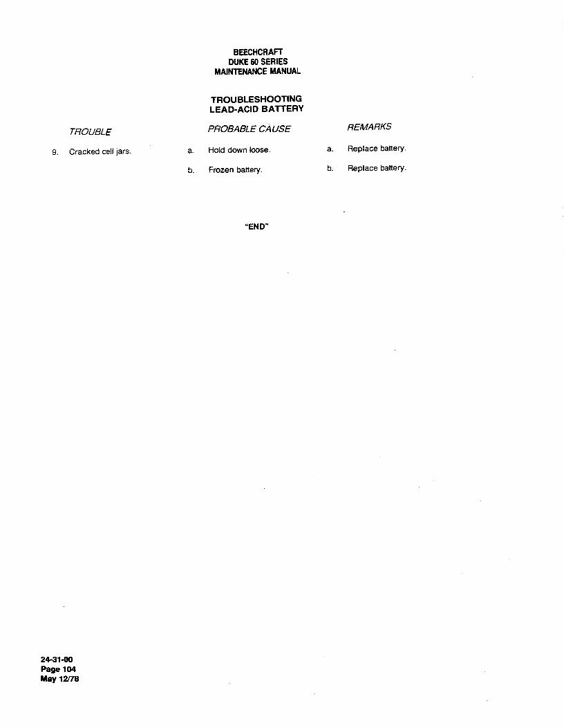
BEECHCRAFTDUKE60 SERIES
MAINTENANCEMANUAL
TROUBLESHOOTINGLEAD-ACID BATTERY
TROUBLE PROBABLE CAUSE REMARKS
9. Cracked cell jars. a. Hold down loose. a. Replace battery.
b. Frozen battery. b. Replace battery.
"END"
24-31-00Page 104
May 12/78

BEECHCRAFTDUKE60 SERIES
MAINTENANCEMANUAL
DC GENERATION - MAINTENANCEPRACTICES b. Cut the safety wire and remove the battery quick-disconnect.
I BATTERY MA/NTENANCE PROGRAM (Airplanes c. On serials P-226 through P-445, equipped withprior to P-446) General Electric air cooled batteries, disconnect the cooling
ducts.A Systematic Battery Maintenance Program should be estab- d. Disconnect the battery vent tubing.lished and carefully followed. e. Cut the safety wire, remove the two nuts from the
battery hold-down bar and lift the battery out of the well.
CAUT/0N PRE-lNSTALLATION INSTRUCTIONS FOR NICKEL-CADMIUMBATTERIES
Methods of servicing lead-acid batteries do notapply for the servicing of nickel-cadmium bat- Unless otherwise indicated by a red waming tag, a nickel-teries. cadmium battery is shipped in fully discharged state and
contains the proper amount of electrolyte.
a. The battery should be removed from the airplane Observe the following precautions to ensure maximum per-for service. formance and to protect the battery warranty.
b. A log of the services performed on each batteryshould be maintained. a. Do not remove the shorting strap until prepared to
c. The battery should be removed from the airplane charge the battery. Batteries from which the shorting strapand serviced after: 100 flight hours or 30 days, whichever has been removed (for even a short peñod of time) must beoccurs first. If the ambient temperatures are above 90°F or considered in an unknown state of charge condition and mustthe time between engine starts averages less than 30 be completely discharged prior to charging and installation.minutes, the duty cycle should be reduced. b. Inspect batteries shipped from the factory for ship-
d. The log of battery services performed should be ping plugs in the vent holes of each of the battery cells. Theevaluated to determine the need to service the battery at the blunt aluminum screws that serve as shipping plugs must beabove recommended intervals or to extend the intervals if removed priorto operation of the battery. The Bunson valves,justified. Accurate water consumption data is a valid baro- included with the battery in a separate plastic bag, shouldmeter to use for adjustment of the servicing intervals. then be screwed into the vent cap assembly in place of the
screw plugs. The Bunson valves will release excessive pres-Since the proper battery servicing requires two days, an sure from gas accumulation to prevent cell rupture.additional battery (or batteries) will be required where air-plane utilization warrants. For additional information on bat-
tery maintenance, refer to Gulton Instructions for Use and NOTECare of Sintered Plate Vented Nickel-Cadmium Storage Bat-teries (P/N ABD-1100), or Marathon Battery Instruction Man- On batteries not equipped with the screw-typeual (P/N BA-89), or Operating and Service Manual for Gener- plugs and Bunson valves, remove the shippingal Electric Nickel-Cadmium Vented-Cell Batteries (P/N GET- plugs and clean the filler cap vent plugs as noted3593A), which ever the airplane is equipped with. Advisory under CLEANINGAND INSPECTION. RetightenCircular AC 00-33, printed by Department of Transporation, the celi vents with the vent plug wrench includedFederal Aviation Administration, is another good source of with the battery.battery maintenance information.
c. Check for a torqueof 6 foot-pounds on the terminalMAINTENANCELOG screws securing the cross links connecting the cells together.
d. Before charging, determine that all cells are pro-Customers are advised to keep a complete and up-to-date perly installed by making a cumulative voltage check.maintenance log on each battery. This information will help e. After determining the battery is in good physicaldetermine the source of any battery problems and will assist condition and is properly assembled, it should be charged asill substantiating warranty claims. A sample format for a outlined under BATTERY CHARGING and the electrolytemaintenance log is illustrated on the following page. level adjusted.
BATTERY REMOVAL BATTERY INSTALLATION
a. Remove the upper access door to the electrical a. Place the battery in the well, install the batteryequipment compartment, aft of LH nacelle firewall. hold-down bar and the two nuts. Safety wire the nuts.
24-314)0Page 201
May 12/78

BEECHCRAFTDUKE60 SERIES
MAINTENANCEMANUAL
MAINTENANCE LOG
Catalog No. Serial No.
Date Installed On
REMOVAL DATE GENERAL END OFAND REASON CONDITION CC CHARGE REMARKS
VOLTAGE RANGEM - Maintenance Lowest Highest Indicate:
F -- Failure 5 Ë Reading Reading Average water added, hardware
(Indicate o i > Minimum Maximum or cell replacements, burns or
Type) 1.50 1.70 u discolorations, etc.
24-31-00Page 202Nov 2/73

BEECHCRAFTDUKE60 SERIES
MAINTENANCEMANUAL
b. Connect the battery vent tubing. c. Do not charge batteries in parallel using thec. On serials P-226 and after, connect the cooling constant current method.
ducts. d. Do not charge individual cells unless the plasticd. install the battery quick-disconnect and safety case is supported on each side. A special frarne may be built
wire. to fit the cell, or two boards or plates may be placed one. Reinstall the upper access door aft of the LH each side of the cell and held together by a C-clamp. The
nacelle firewall. sides of the cell must be kept flat during charging.e. Perform necessary inspection, cleaning and repairs
BATTERY CHARGING before charging.f. Do not energize charging equipment until after the
The two basic methods of charging nickel-cadmium battery has been connected to the charging circuit.batteries are the constant potential and constant current g. When charging a battery in the shop, amethods. Variations of the two basic methods may be thermometer should be placed so that the bulb is below andincorporated in automatic equipment. between the top of the cells. Do not place on charge any
battery that has a temperature of 100°F or higher.WARNING h. The foam sometimes seen in cells during charging
does not indicate a defect. Foaming usually occurs afterComplete servicing of the battery is required if water is added and will disappear after a few cycles ofthe battery is subjected to more than 32 volts operation.for 2 minutes.
The various charging procedures for the nickel-cadmiumSPECIAL NOTES ON CHARGING battery are outlined in the following paragraphs:
The following special comments are made with respectto CONSTANTCURRENTCHARGINGcharging nickel-cadmium batteries:
CAUTIONa. Charging is most efficient at battery temperatures
between 40°F and 80°F. Monitor the battery closely during chargingb. Two or more batteries may be charged in parallel (especially during the latter stages) to prevent
on a constant potential charging bus, provided the charging an overcharge that will heat up and damage orequipment has the proper current producing capability. destroy the battery.
AIRCRAFT BATTERY INSTALLATION CHECKLIST
INSPECT FOR VISIBLE DAMAGE
REMOVE SHIPPING HARDWARE
ENSURE THAT ALL CONNECTORS ARE PROPERLY TIGHTENED(Do not level electrolyte on new battery prior to charging.)
CONNECT BATTERY CORRECTLY TO CHARGER
CHARGE BATTERY (Constant current recommended)
MEASURE END-OF-CHARGE VOLTAGE
REST BATTERY 2 TO 4 HOURS
CHECK ELECTROLYTE LEVEL
CLEAN AND CHECK A/RCRAFT'S BATTERY CONNECTOR
8 INSTALL BATTERY
CHECK AIRCRAFT'S BATTERY CHARGER SYSTEM
24-31-00Page 203Nov 2/73

BEECHCRAFTDUKE60 SERIES
MAINTENANCEMANUAL
PREVENTIVE MAINTENANCE CHECKLIST NICKEL-CADMlUM 19 CELL AIRCRAFT BATTERY-CONSTANTCURRENT CHARGE,ROOM TEMPERATURE AT C/10 RATE
sEAENCTBAFOVRISIBLE
DAMAGE
WASH VENT CAPS
RECONDITION 2°
DISCHARGE AND SHORT
CONSTANT CURRENT CHARGE 1 2 3 4 5 6 7 8 9 10 11 12 13 14 15 16TIME (HOUR5)
MEASURE END-OF-CHARGEVOL TAGE Constant Current Charge at C/10 Rate
Figure 201REST BATTERY 2 TO 4 HOURS
LEVEL ELECTROLYTE amperes per hour for the 13.5 ampere-hour battery forseven hours. The slow charging rate is 1.4 amperes per hour
MEASURE ELECTRICAL LEAKAGE for the 13.5 ampere-hour battery for 14 hours. See Figure201 for slow (capacity/10), single rate, constant current
DISCHARGE, MEASURING CAPACITY charging voltage. A battery is charged at the START rateuntil the battery temperature takes a sharp rise or until theterminal voltage (while battery is charging) reaches 29.5
Although slower, the constant. current method is the volts (for a 24-volt 19-cell battery). When the 29.5 voltrecommended way of charging the battery. Most shops are point is reached or the temperature takes a sharp rise, theequipped with constant current chargers. In cases where the charging current is reduced to the FINISH rate andchargers are limited to 6 ampere capability, it will be continued until one-third of the initial charge innecessary to start the charge of most batteries at a lower ampere-hours is added. When the voltage rises to 29.5 volts,rate than recommended on the battery nameplate. If a the charge received by the battery is approximately equalreduced rate is used, a longer charging time is required. The to that removed when it was previously discharged. Theconstant current method is much more effective in addition of ampere-hours at the FINISH rate equal tocorrecting cell imbalance and temporary loss of capacity, one-third of the ampere-hour input at the START rate willand it permits easy computation of the charge capacity in usually ensure that the battery is fully charged.ampere-hours. When using this method, one must usuallymonitor and maintain the constant current by manually NICKEL-CADMIUM 19 CELL 34 AHadjusting the charger· 2oo AIRCRAFT BATTERY -CONSTANT
POTENTIAL CHARGE AT 28.5The following procedures for constant current charging are 180 VOLTS, ROOM TEMPERATURE,
generally applicable to all aircraft nickel-cadmium storage ggeFULLY DISCHARGED BATTERY.
batteries:T40 --
a. The time required to charge a nickel-cadmium i 120 estorage battery varies with respect to the dischargingcurrent, capacity rating, and amount of charge already in 4the battery. If fully discharged, the battery should becharged to 140 percent of its nortiinal ampere-hour rating.
b. When trsing she constant current method of \ 2 -
charging, the battery may be charged in two steps by usingthe START rate of current and the FINISH rate of current. 20(Lower starting rates may be used if required by such ' ' ' ' 'factors as equipment limitations.) These rates are usually o .2 .4 .6 .a i o i 2 a 4 5 6
given on the battery nameplate. The two step method is TIME ( HOURS ) 9440,23
commonly used by the military. Single rates, slow or fast,are usually preferred by commercial service shops because Constant Potential Chargingof their simplicity. The single fast charging rate is 2.7 Figure 202
24-31-00Page 204Nov 2/73
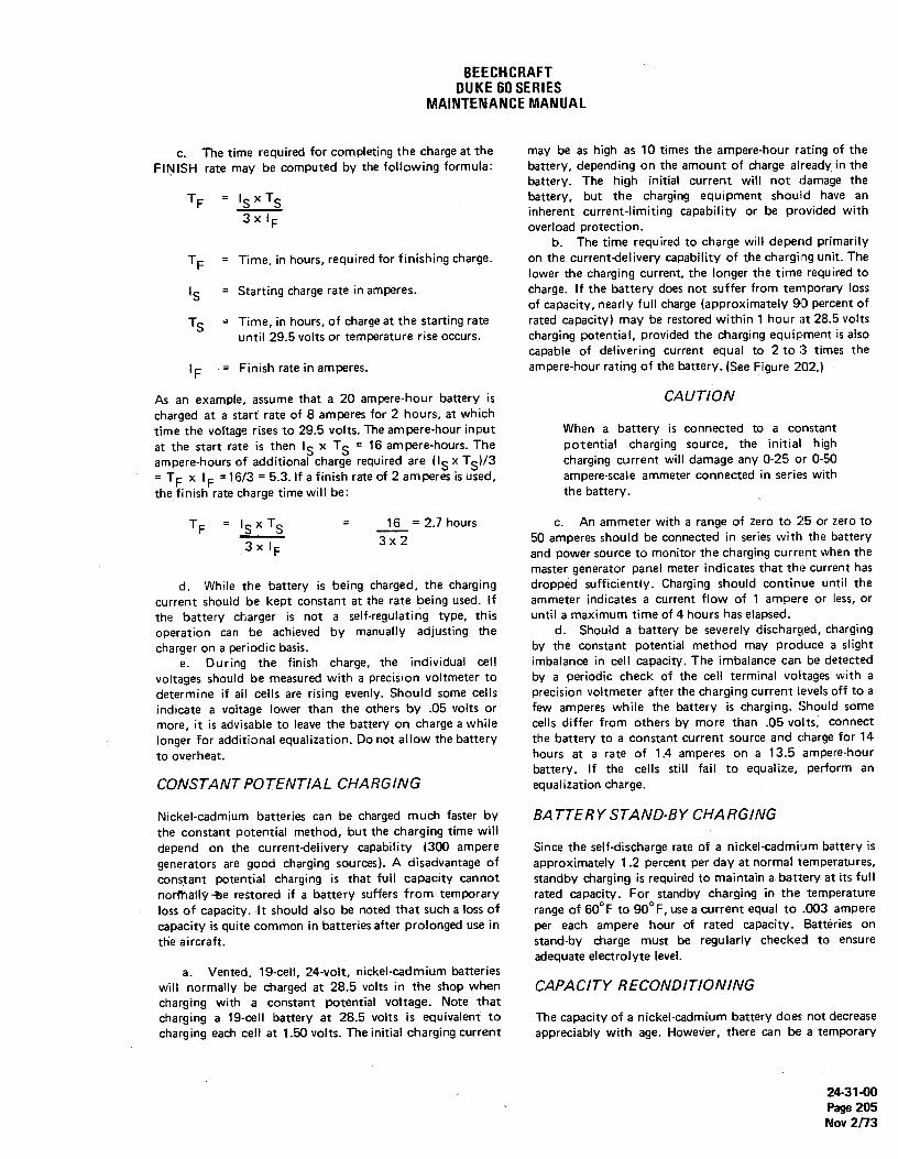
BEECHCRAFTDUKE60 SERIES
MAINTENANCEMANUAL
c. The time required for completing the charge at the may be as high as 10 times the ampere-hour rating of theFINISH rate may be computed by the following formula: battery, depending on the amount of charge already in the
battery. The high initial current will not damage theTF - IS S battery, but the charging equipment should have an
3 x I inherent current-limiting capability or be provided withF overload protection.
b. The time required to charge will depend primarilyTF = Time, in hours, required for finishing charge. on the current-delivery capability of the charging unit. The
lower the charging current, the longer the time required toIS = Starting charge rate in amperes. charge. If the battery does not suffer from temporary loss
of capacity, nearly full charge (approximately 90 percent ofTS = Time, in hours, of charge at the starting rate rated capacity) may be restored within 1 hour at 28.5 votts
until 29.5 volts or temperature rise occurs. charging potential, provided the charging equipment is alsocapable of delivering current equal to 2 to 3 times the
IF = Finish rate in amperes, ampere-hour rating of the battery.(See Figure 202.)
As an example, assume that a 20 ampere-hour battery is CAUTIONcharged at a start rate of 8 amperes for 2 hours, at whichtime the voltage rises to 29.5 volts. The ampere-hour input When a battery is connected to a constantat the start rate is then IS S
= 16 ampere-hours. The potential charging source, the initial highampere-hours of additional charge required are (IS X S)/3 charging current will damage any 0-25 or 0-50= TF 'F
=16/3 = 5.3.lf a finish rate of 2 amperes is used, ampere-scale ammeter connected in series withthe finish rate charge time will be: the battery.
TF ISX S= 1= 2.7 hours c. An ammeter with a range of zero to 25 or zero to
3 x I 3 x 2 50 amperes should be connected in series with the batteryF and power source to monitor the charging current when the
master generator panel meter indicates that the current hasd. While the battery is being charged, the charging dropped sufficiently. Charging should continue until the
current should be kept constant at the rate being used, if ammeter indicates a current flow of 1 ampere or less, orthe battery charger is not a self-regulating type, this until a maximum time of 4 hours has elapsed.operation can be achieved by manually adjusting the d. Should a battery be severely discharged, chargingcharger on a periodic basis. by the constant potential method may produce a slight
e. During the finish charge, the individual cell imbalance in cell capacity. The imbalance can be detectedvoltages should be measured with a precision voltmeter to by a periodic check of the cell terminal voltages with adetermine if all cells are rising evenly. Should some cells precision voltmeter after the charging current levels off to aindicate a voltage lower than the others by .05 volts or few amperes while the battery is charging. Should somemore, it is advisable to leave the battery on charge a while cells differ from others by more than .05 volts, connectlonger for additional equalization. Do not allow the battery the battery to a constant current source and charge for 14to overheat. hours at a rate of 1.4 amperes on a 13.5 ampere-hour
battery. If the cells still fail to equalize, perform anCONSTANT POTENTIAL CHARGING equalization charge.
Nickel-cadmium batteries can be charged much faster by BATTERYSTAND-BYCHARGINGthe constant potential method, but the charging time willdepend on the current-delivery capability (300 ampere Since the self-discharge rate of a nickel-cadmium battery isgenerators are good charging sources). A disadvantage of approximately 1.2 percent per day at normal temperatures,constant potential charging is that full capacity cannot standby charging is required to maintain a battery at its fullnormelIÿ±e restored if a battery suffers from temporary rated capacity. For standby charging in the temperatureloss of capacity. It should also be noted that such a loss of range of 60°F to 90°F, use a current equal to .003 amperecapacity is quite common in batteries after prolonged use in per each ampere hour of rated capacity. Batteries onthe aircraft. stand-by charge must be regularly checked to ensure
adequate electrolyte level.a. Vented, 19-cell, 24-volt, nickel-cadinium batteries
will normally be charged at 28.5 volts in the shop when CAPACITY RECONDITIONINGcharging with a constant potential voltage. Note thatcharging a 19-cell battery at 28.5 volts is equivalent to The capacity of a nickel-cadmium battery does not decreasecharging each cell at 1.50 volts. The initial charging current appreciably with age. However, there can be a temporary
24-31-00Page 205Nov 2/73

BEECHCRAFTDUKE60 SERIES
MAINTENANCEMANUAL
loss of capacity under certain duty cycles. A temporary loss inch above the baffle. Do not remove any electrolyte fromof capacity is normally an indication of imbalance between the cells.cells. Imbalance can be caused by differences in e. Measure and record the voltage at 24 charge hourstemperature, charge efficiency, self-discharge rate, etc. The and compare with the 20 hour reading. If the 24 hourpurpose of reconditioning is to restore a battery to its full voltage reading is below the 20 hour reading by more thancapability and to prevent premature damage and failure. .04 volts, replace the cell. Also replace any cell thatEffective reconditioning requires specific procedures for measured below 1.50 volts at 24 charge hours. Aftercertain periods of time. No step in the procedure can be removing the battery from charge, measure the electrolyte.eliminated nor can any time period be shortened and still temperatures. If the electrolyte temperature of any cell isyield effective battery reconditioning. greater than 30°F
above the ambient, replace that cell.
FREQUENCY OF RECONDITIONING B A TTERY ELECTROLYTE LEVELADJUSTMENT
Due to the variables involved in usage, it is impossible toestablish a time interval for reconditioning that will cover Although the electrolyte level in the nickel-cadmiumall batteries. Until service experience dictates otherwise, a battery varies with the state of charge, it should be visiblevisual and electrolyte check of the battery should be made above the bottom of the baffle when the battery is fullyafter the first 50 hours of flight. If the condition of the charged. When the state of charge of the battery is low, thebattery is normal and the level of electrolyte in the battery plates absorb some of the electrolyte, then release it as theis satisfactory, schedule the initial reconditioning at 100 battery is recharged. The electrolyte level on any batteryhours. Repeat the reconditioning procedure outlined below must be adjusted after a full charge and a two to four hourat 100-hour intervals until servicing experience justifies a rest on open circuit. Check the electrolyte level of thechange. battery (fully charged) in the following manner:
NOTE CAUTION
The log of battery services performed should be Never use acid or tools contaminated with acidevaluated to determine the need for servicing during this adjustment, for both bodily injurythe battery at the above recommended intervals and equipment damage may result. If possible,or extending the intervals. Accurate water use equipment reserved for nickel-cadmiumconsumption data is a valid barometer to use batteries. If lead-acid battery equipment mustfor adjustment of the servicing intervals, be used, remove all possible acid contamination
with a sodium bicarbonate solution and rinse.Even minute traces of acid can damage a
RECONDITIONING PROCEDURE nickel-cadmium battery.
a. Discharge the battery at a current equal to or lessthan the one-hour rate. Short out each cell as it drops a. Remove the battery from the aircraft.below .5 votts. The cells may be shorted by clips or by b. With the battery removed from the. aircraft,wires having clips on each end. Allow the shorts to remain remove the filler cap vent plug on each cell, one cell at aon the cells for a minimum of 16 hours, and preferably for time.24 hours. c. Insert a transparent tube (approximately 6 inches
b. Remove the shorting clips and charge for 24 hours long and 1/4 inch in diameter) perpendicularily into theat 1.1 amperes for a 13.5 ampere-hour battery. After filler well until the open end rests lightly on the cell baffle,approximately 5 minutes of charge, measure the individual then place the index finger over the top open end andcell voltages. If any cell voltage is greater than 1.50 volts, withdraw the tube.add distilled water. The amount of water required isapproximately 1 'Ed ßef rated ampere-hour capacity, forexample, a 13.5 ampere-hour cell may require about 13.5 CAUTIONcc of water at this time.
c. After approximately 10 minutes of charge, Do not push down, for the light material of theremeasure the cell voltages. Replace any cell that measures baffle will give enough to result in a falsebelow 1.20 volts or above 1.55 volts. indication of the electrolyte level.
d. Continue charging for 20 hours. After 20 hours ofcharging, measure and record the individual cell voltages. If d. The electrolyte level of a fully charged batterynecessary, add distilled water to level the cell 1/8 to 1/4 should be between 1/8 and 1/4 inch above the bottom of
24-31-00Page 206Nov 2/73

BEECHCRAFTDUKE60 SERIES
MAINTENANCEMANUAL
the baffle. If the level of liquid in the tube exceeds 1/4 possible damage to an expensive precision meter). Connectinch, remove the excess with a syringe or squeeze bottle. If the positive terminal of the ammeter to the positive batterythe level of the electrolyte is less than 1/8 inch above the terminal and the negative ammeter terminal to the batterybottom of the baffle, add distilled water with a syringe or case. Decrease the ammeter current range to obtain asqueeze bottle. readable value of current and record the value. Perform the
same measurement at the negative battery terminal byconnecting it to the negative terminal of the ammeter and
CAUTION connecting the positive terminal of the ammeter to thebattery case. If the current reading at either terminal is
Tap water contains minerals, chlorines, more than 13.5 ma on 13.5 ampere-hour batteries, thesoftening agents, and other foreign materials battery should be cleaned. This test should be made againwhich will contaminate a storage battery and after the battery has been completely cleaned and charged.shorten its life. If the current measure is again more than 13.5 ma on 13.5
ampere-hour batteries, it may be assumed that one of thecells has a seal leak. That cell may be found by measuring
WARNING connector-to-battery case voltages. The lowest voltages witIoccur at the connectors on each side of the defective cell. A
The battery may be damaged if the proper cell found leaking in this manner should be replaced.procedure is not followed when adding distilledwater to the cells.
CAPACITY CHECK
e. Clean and reinstall the filter cap, vent cap, vent a. Discharge the battery at a rate of 6.0 amperes onplugs and check the battery terminal links for tightness. 13.5 ampere-hour batteries until an average voltage of oneDiscolored links or melted nylon around cell terminals voit per cell is reached. Measure the time required for theindicate loose link connections, battery to reach that discharged state. Any battery that
discharges to one vott per cell in 84 minutes or less shouldbe given another reconditioning (deep) cycle.
CAUTION b. After the second reconditioning cycle, recheck thebattery capacity by discharging at the rate used in step "a".
If water or electrolyte is spilled into the battery Measure the individual cell voltages after 84 minutes ofcontainer, the resultant electrolyte corrosion discharge. If any cell is below one volt, replace it.may cause battery failure. The battery casemust be cleaned as instructed in CLEANINGAND INSPECTION. CLEANING AND INSPECTION
a. Scrub each cell with a 5 percent solution of boricELECTRICAL LEAKAGE CHECK acid in water, but take great care to prevent the solution
from entering the cell.The self (internal) discharge rate of a vented b. Wash each cell off under running water and drynickel-cadmium battery cell is ¡n the order of C/1000 when with an air hose or clean absorbent towel.fully charged. "C" in this formula represents capacity in c. Inspect each cell for defects such as cracks, holes,ampere-hours. This is about 13.5 ma for 13.5 ampere-hour or burn spots. Replace defective cells with new or rebuiltbatteries. The only pertinent measure of external leakage is cells.the rate of discharge caused by the leakage. The rate is d. Niake sure that battery hardware is clean and insignificant only when it approaches the rate of internal good mechanical condition. Wash the hardware, liners, case,leakage. Therefore, external leakage need be considered cover, and other associated parts in a warm soapy solutionexcessive only when an ammeter shorting the battery to remove accumulated dirt and carbonate deposits. Use apositive -os negative terminal to the battery case indicates stiff brush to remove heavy deposits. After washing, rinse13.5 ma or more on 13.5 ampere-hour batteries. Any the parts free of soap and spread them out to dry.current less than the preceding limits indicates a magnitude e. Remove corrosion preventive from connectors,of leakage that has a negligible effect on battery screws, nuts, and washers with alcohol or by degreasing.performance. f. Wash vent caps thoroughly with hot \Nater and no
soap.Perform the following test to determine if external leakage g. After the parts are dry, sort out damaged oris sufficient to necessitate cleaning the battery. Set the heavily corroded pieces. Scrap any links having burns,range selector of a multi-range ammeter to the 500 ma scale bends, or defective nickel plating. If a link is tarnished ator higher (a low cost meter is recommended to preclude the terminal connection, it should be polished with a wire
24-31-00Page 207Nov 2/73

BEECHCRAFTDUKE60 SERIES
MAINTENANCEMANUAL
brush. It is recommended that new terminal screws and nuts e. Remove the POSITIVE cable terminal from thebe used to ensure proper electrical connection. batteries.
h. Check the battery receptacle for burns, cracks, and f. Remove the bus bar interconnect from the twobent or pitted terminals. Defective receptacles can overheat, batteries.cause arcing. and decrease output voltage to result in prema- g. Remove the batteries frorn the airplane.ture battery failure.
i. Scrap bent or torn battery cases and covers thatare beyond repair. BATTERY INSTALLAT10N
j. Replace or repair loose or damaged cover gasketsand cell holddown bars. a. Position the batteries in the battery box.
b. Coat the battery terminals and cable terminals witha lightmating of petroleum jelly.
NOTE
Refer to the maintenance manual of the batterymanufacturer for additional details on battery dis- CAUTIONassembly and assembly.
If the POSITIVE battery temlinal is not marked÷, POS or painted red and the NEGATIVEbat-
BATTERY MAINTENANCE PROGRAM (P446 and tery terminal is not marked -, NEG or paintedafter) black, use a voltmeter to determine the battery
polarity before connecting the battery in the air-A systematic battery maintenance program should be estab- plane. Reverse polarity will destroy the diodeslished and carefully followed. and other electronic components in the electrical
system.a. The batteries should be removed from the airplane
for service.b. A log of the services performed on each battery
should be maintained. c. Position the POSlTIVE cable terminal on the bat-c. The battery should be removed from the airplane tery and secure.
and serviced after: 100 flight hours or 30 days, whichever d. Position the NEGATIVEcable terminal on the bat-occurs first. If the ambient temperatures are above 90°F or tery and secure.the time between engine starts averages less than 30 e. Install the bus bar interconnect on both batteries.minutes, the duty cycle should be reduced. f. Remove any excess petroleum jelly from the termi-
d. The log of battery services performed should be nals.evaluated to determine the need to service the batteries at g. Position the battery box lid on the battery box andthe above recommended intervals orto extend the intervals if secure.justified.Accurate water consumption data is avalid barome- h. Install the nuts on the hold-down strap bolts.ter to use for adjustment of the servicing intervals. i. Install the access door.
BATTERY REMOVALBATTERY CLEANING
a. Remove the upper access door to the electricalequipment compartment aft of the left nacelle firewall. For peak performance, the batteries must be kept clean and
b. Remove the nuts from the hold-down strap bolts. dry. if foreign materials are present in sufficient quantities,c. Release the battery box lid Iatches and remove the the resultant deposits may form conductive paths that permit
box lid. a rapid.discharge of the batteries. To prevent thecollection ofd. Remove fhe TNEGÁTIVE battery cable from the suchlieposits, use the following steps in cleaning the bat-
batteries. teries:after each 100 hours of service or every 30 days,whichever occurs first
CAUT/ONa. Remove the batteries as described in the section
Always remove the ground cable terminal first BA L !±NY REMOVAL.and install it last to prevent accidental short cir- :b. Ensure that the battery cell filler caps are tight incuits. place.; Brush dirt off with a stiff bristle brush.
24-31-00Page 208May 12 8

BEECHCRAFTDUKE60 SERIES
MAINTENANCEMANUAL
CAUTION BATTERY SERVICING
Never use a wire brush or brush with a metal The batteries should be maintained in a fully charged state atconstruction for this purpose as short circuiting all times and the electrolyte level checked at regular inter-or other damage may result. vals. Clean fully charged batteries will provide peak perform-
ance. Never add anything but distilled water when adjustingthe electrolyte level in the batteries. If electrolyte is added
c. Scrub the batteries with a solution of ammonia or each time the level in the batteries are low, a high concentra-bicarbonate of soda (one part of soda to a gallon of water). tionof electrolyte may cause dissolution of the plates. UnderThis will neutralize any electrolyte sprayed or spilled out. high temperature conditions, this may be indicated by the
presence of black particles in the electrolyte of the affectedcells.
CAUTIONNOTE
Entrance of ammonia or soda solution into abattery ceit will neutralize the cell electrolyte. Do not fill the batteries over one-half inch aboveNever use solvents to clean the batteries, for the separators. Only lead-acid equipment shouldthese may damage the battery case. be used when servicing lead-acid type batteries.
RECHARG/NG BATTERIES US/NG AUX/L/ARYd. Rinse the batteries with clear water, then sponge POWER
off the excess water. Allow the batteries to air-dry.e. Wash the battery filler caps with clean hot water The following steps should be used in using auxiliary power
and no soap, then examine the vent holes in the battery filler to recharge the batterycaps to make sure they are clear.
f. Inspect the battery for cracks, holes or burn spots. a. Place the battery master switch in the on position.Replace if necessary. b. Place both alternator switches and all electrical
g. Make sure that all batteries hardware is clean and and avionics equipment switches in the off positions.in good mechanical condition, c. Connect the auxiliary power unit to the external
power receptacle.
NOTE CAUTION
If additional cleaning of the battefy terminalsand Make certain that the battery switch is in the oncable terminal is required, use a wire brush and position, all avionics and electrical switches arebrighten up the terminals to ensure a good elec- in the off positions and batteries are in the sys-trical connection. tem before connecting an external power unit.
This protects the electrical voltage regulatorsand associated electrical equipment from volt-age transients (power fluctuations).
BATTERY BOX CLEANING
Thtflatteg box is vented overboard to dispose of electrolyte . d. Set the output of the auxiliary power unit at 27.0 toand hydrogen gas fumes discharged during normal charging 28.5 vdc.operation. To ensure the disposal of these fumes, the vent e. Place the auxiliary power unit in the on position.hose connections at the battery box should be checked fre-quently for obstructions. The battery box should be washed If the battery master relay will not close, the batteries must beout thoroughly and dried each time the battery is removed removed from the airplane for recharging. Check the batteryand cleaned. master relay control circuit for a malfunction.
"END"
24-31-00Page 209
May 12/78

BEECHCRAFTDUKE60SERIES
MAINTENANCEMANUAL
DC GENERATION-MAINTENANCE PRACTICES observing the loadmeter for load change. If the load changeis satisfactory and the light has gone out, the battery is
BA T7ERY CHARGE CURRENT DE7ECTOR SYS- charged and the system is operating properly.I TEM FUNCTIONAL CHECK (Prior to P-446) 2. Battery is charged and is being excessively
overcharged. If the loadmeter stabilizes and indicates anNOTE unsatisfactory load change when the battery is turned OFF,
the battery is overcharging excessively and the light shouldSatisfactory load change as used herein, is de- not have gone out. Check the battery and charging circuit forfined as deflection of the loadmeter needle equal condition and proper operation.to or less than a .025 load change (approximate-ly 3 amperes) for airplanes with a 13.5 ampere- NOTEhour battery. A load change of .025 or .050 isbarely perceptible, As the battery approaches full charge, the
charge current may decrease slowly enough thatThe system may be checked in the airplane with either en- the loadmeter would appear to stabilize beforegine running. After the engine is started, turn the applicable the charge current has decreased enough for thegenerator ON. After a time delay of approximately 6 seconds light to go out.(provided the battery is sufficiently discharged and will accepta charge), the amber caution light (BATTERY CHARGE) In the event of doubt as to the amount of charge current afterlocated on the instrument panel should illuminate. The light the loadmeter appearsto have stabilized, an ammeter can beshould remain illuminated until the battery is recharged. Un- integrated into the charging circuit. Install the ammeter andder normal circumstances, the battery should be recharged check the charge current as follows:and the light should go out within 5 minutes. However. if thebattery has had unusually low or high drain, the recharge (a) An ammeter that will indicate approxi-time could be considerably shorter or longer. When the light mately 10 amperes, lead lines that will reach from the batterydoes go out. turn the battery switch OFF while observing the relay to the pilot's compartment and an on-off switch for theaffected loadmeter; the loadmeter should indicate a satisfac- ammeter leads will be required.tory load change. (b) Wire the on-off switch into one of the
leads and connect the leads to the ammeter.Listed below are possible situations that could be experi- (c) Connect the negative side of the amme-enced and corresponding action that is recommended: ter to the battery side of the battery relay and the positive side
of the ammeter to the generator side of the battery relay.a. Light does not illuminate - If the bulb is operational (d) With the switch in the ammeter lead
but the light does not come on within approximately 6 sec- turned off, start either engine. Allow the battery to chargeonds after the operating generator is turned ON, it is possible until the loadmeter appears to stabilize.that the battery is not sufficiently discharged to accept a (e) Turn the switch in the ammeter lead oncharge. This can be determined by turning the battery OFF and turn the battery switch OFF, in that order to prevent awhile observing the loadmeter needle deflection. A satisfac- current surge and possible damage to the ammeter.tory load change indicates the battery is charged and the light (f) Note the charge current as indicated onshould not be on. An unsatisfactory load change indicates the ammeter. The charge current should decrease until thethe light should be on and that there is a malfunction in the light goes out at approximately 3 or 7 amperes and maydetector system. Repair or replace the defective parts and continue to decrease to a lower level.repeat the functional check. If the battery was not dischargedenough to accept a charge, turn the generator OFF and Repair or replace any parts found to be defective and repeatpartially discharge the battery by operating electrical equip- the functional check.ment Repènt the functional check.
b. Light stays on - Check the following possibilities: 3. Battery is charged and is not being excessive-
ly overcharged. If the light is on and the charge current has1. Battery is partially discharged and is charg· dropped to a satisfactory level, the detector assembly is
ing. If the light stays on after charging for approximately 5 malfunctioning and should be replaced.minutes, careful attention should be given the airplane load-
meter. With a constant load on the airplane electrical system, (a) Light is erratic or does not operate incontinue to charge the battery. The loadmeter should indic- unison with suitable charge current values as previously out-ate a constantly decreasing charge current until the battery is lined. Check the wiring and detector assembly for propercharged. When the loadmeter appears to stabilize (see operation. Repair or replace defective parts and repeat theNOTE in condition 2 below), turn the battery OFF while functional check.
"END" 24-32-00Page 201
May 12/78

BEECHCRAFTDUKE60 SERIES
MAINTENANCEMANUAL
EXTERN A L POWER - MA INTEN A NCE unknown, determine the polarity with a voltmeter beforePRACTICES connecting the unit to the aircraft.
b. Before connecting the external power unit, turnThe aircraft electrical system is protected against damage . off all radio equipment and generator switches, but leavefrom reverse polarity by a relay and diodes in the external the battery on to protect transistorized equipment againstpower circuit. The external power receptacle is located just transient voltage spikes.outboard of the left engine nacelle. The receptacle isdesigned for a standard AN type plug. To supply power forground checks and air conditioner operation, a ground CAUTIONpower source capable of delivering a continuous load of300 amperes at 24 to 30 volts is required. Use of an When the battery switch is turned OFF forinadequate ground power unit can cause a voltage drop extended ground power operation, place anbelow the drop-out voltage of the starter relay, resulting in external battery in parallel with the output ofrelay chatter and welded contacts. By the same token, a the external power unit before operating anymaximum continuous load in excess of 350 amperes will transistorized avionics equipment.damage the external power relay and power cables of theaircraft. c. If the unit does not have a standard AN plug,
check the polarity and connect the positive lead from theObserve the following precautions when using an external external power unit to the center post and the negative leadpower source: to the front post of the aircraft's external power receptacle.
The small pin of the receptacle must be supplied with + 24a. Use only an auxiliary power source that is VDC to close the external power relay that provides
negatively grounded. If the polarity of the power source is protection against damage by reverse polarity.
"END"
24-40-00Page 201Nov 2/73

BEECHCRAFTDUKE60 SERIES
MAINTENANCEMANUAL
ELE CT RICAL LOAD DI STRI BUT ION - DUAL BUS CONFORMITY lNSPECTIONMAINTENANCE PRACTICES (Figure 201)
The dual bus feeder diodes should be inspected at 600 A dual bus conformity inspection shoud be performedflight -hour intervals as instructed under PERIODIC whenever the console or subpanel bus system has beenINSPECTION OF DUAL BUS FEEDER DIODES. modified or whenever repairs have been made that mayWhenever the dual bus has been modified or extensive result in the dual bus loops being interconnected or open.repairs have been made that could result in the dual bus Either battery or auxiliary power may be used whenloops being interconnected or open, it is necessary to conducting this inspection. Check for correct circuitperform a DUAL BUS CONFORMITY INSPECTION. This connections by actual operation of the circuit as describedwill ensure that the original design of the dual bus is by the appropriate power distribution circuit in the Wiringmaintained. Diagram Manual, P/N 60-590001-29. The conformity
inspection may be performed as follows:PERIOD/C INSPECTION OF DUAL BUSFEEDER D/ODES a. Open the four 50 ampere bus feeder circuit(Figure 202) breakers labeled ELECTRICAL POWER on the right circuit
breaker subpanel.An open or shorted dual bus feeder diode cannot be b. Turn the battery ON. External power may be used.detected during the normal operation of the aircraft c. Close the LH # 1 bus feeder circuit breaker, checkelectrical system. Should a malfunction occur which would each circuit and record the results.cause a bus isolation limiter to open, such as a ground fault d. Open the LH # 1 bus feeder circuit breaker andon a generator bus, an open dual bus feeder diode could not close the LH # 2 bus feeder circuit breaker. Repeat thesupply power to its respective dual bus loop. A shorted circuit checks and record the results.diode would not isolate its respective dual bus from a e. Open the LH # 2 bus feeder circuit breaker andground fault. The inspection procedure outlined here will close the RH # 1 bus feeder circuit breaker. Repeat theensure the dual bus capability. The inspection may be circuit checks and record the results.performed at a normal periodic inspection of the aircraft f. Open the RH #1 bus feeder circuit breaker andand either battery power or an auxiliary ground power unit close the RH # 2 bus feeder circuit breaker. Repeat theconnected to the external power receptacle may be used. A circuit checks and record the results.suggested inspection procedure follows: g. If any of the results that have been recorded reveal
a discrepancy, locate and repair to obtain the desired result.a. Remove all power from the aircraft. h. Close all circuit breakers and return the aircraft tob. Open the four 50 ampere bus feeder circuit normal.
breakers labeled ELECTRICAL POWER on the right circuitbreaker subpanel. WS
c. Turn the battery and/or auxiliary ground powerunit ON.
d. Confirm the continuity of each dual bus feeder 50A 50A SOA SOAdiode. This may be accomplished by closing a singleELECTRICAL POWER feeder diode circuit breaker andconfirming the presence of voltage on the corresponding #1 #2 #1 #2dual bus loop. The presence of voltage may be determined FEEDERby the operation of circuits which receive power from thedual bus loop. Refer to the Power Distribution Schematic, Dual Bus Conformity InspectionFigure 202, or to the applicable wiring diagram for the Figure 201appropriate aircraft serial in the Wiring Diagram Manual,60-590001-29, to determine which circuits receive power ELECTRICAL UTILIZATION LOAD CHARTfrom each dual bus loop. Repeat for each circuit breaker.
e. Confirm that each dual bus is not shorted. This The following chart provides information pertaining to themay be accomplishedby closing a single ELECTRICAL capacity of the generator for supplyingthe electrical loadPOWER feedei circuit breaker and determining that no on the aircraft while maintaining a full charge on thevoltage is present at the load side of each of the three battery. To determine the total electrical load of theremaining ELECTRICAL POWER feeder circuit breakers. aircraft, add the continuous load for standard equipment toRepeat for each circuit breaker. the load of the optional equipment installed in the aircraft
(accessories and radio). Since the aircraft is equipped withShould any diode prove to be either shorted or open,.this two 28 volt, 125 ampere generators, the total load shall notdiode must be replaced and the inspection repeated. After exceed 80 percent of the total generating capacity. When ancompletion of the inspection, reset all circuit breakers and item of equipment functions at various times in differenttighten all connections securely. Ensure that all wires and systems, the load per unit value listed in the chartterminals are not chafing against the aircraft structure. represents the highest value required to operate thatCheck the system for normal operation. particular unit in the various systems in which it functions.
24-50-00Page 201Nov 2/73

BEECHCRAFTDUKE60 SERIES
MAINTENANCEMANUALESHOLOliCNT TE NAL FCVERE EANAL
BATTERYBATTERY BLLAY
BA FTE BY SWITCH
LIMITERON
T GE 225A
5 rEAF TER
LOADMETFR LOADMETER
LEFT REVERSE 12DA 120AREVERSE RK:HT
GENEAATOR CURAENT cuRRENT GFNERATORDIODE
OA
VOLTACCE R&GULATONI LF ACFLL VOLTD^GE NEGULATOR
ER OLTAGERELAY
LA OVER LTAGERELAY
45A lyr)A 1WlA 49A
Ritin1 WINOSilif LU LEFI WINUSHILLOANFI ICE INvENTER ANTI ICE Av10NK:5(IF INSTALLED) STANDBY INV[IITER
LEFT AvrONICSE1.ECTRICAL POWER LEFTAviONICS
ELECTRICALPOWEB CONTROL Bus MI * POWERAVt0N1CS
2A 25A IST AND 3nO AOW 2ND ANO arH now BUS 25A
AVIGANIEC5CIRCUIT ICAAlc5CIRCUIT
SOA BOA SOA
AVIONACSPOWERCIRCUITPALO
O^60A EC
NLY 1 N 2OÑ Si
2
I SERIALSP-243 THAu P.sas Av!ONICS :ANO THOSE PRION AIACAAFT MASTE R OF FWHICH HAVE INSTALLED SWITCH
KiTPNGO-3005
PAINHOUGHP61 P62ANDAFlER
LEFT FUEL QUANTITY CtGARETTE LIGHTER
FUEL FLOW 5TALL WTR
\ CYLINOFR HEAD TEMPERATURE L AP AND LANDiNG GE AN INDICATORS
OIL TEMPERATURE VOt.I MrTER [FREBOC5T 4TURNANDSLIP
) COWLFLAPS CA8tNPRESSURECONTROL
LIUANANOSLIP LEFTPITOTHEATP-4THROUGMP61
FLAPANDLANDINGGEARINDICATORS MSURFACEDEICEVENT DLOWER j ANNUNCIATOR R1GHT WINDSH1ELD ANTI ICE (IF INSTALLEOl
AIRCONOITIONER CAGINPRESSURECONTROL OVERVOLTAGERELAY
CABIN TEMPERATURECONTROL LEFT PITOT HEAT FLAP MO
\ ROTATING BEACON SURFACE DEtCE STARTER AND IGN1TION P 4THROUGH P 61 --|
| LEFT LANDINGL1GMT WINDSHIELD OEICE (tF INSTALLEDI LANOING GEAR
| TAXI LiG VTATRELAV5 RIGHT LANDING LIGHTS
I WING ICE LIGNT LEFT FUEL VE HEAT NAVIGATION LIGHTScorator S INSTRUMENT LIGHTS PITCH TRIM PILOT S INSTRUMENT LIGHTS
DOME ANO READING LIGHTS ( HOUR METER SUSPANEL LIGNTS
P62ANDAFTER I
(VENT BLOWER , PA THROUGHP-61 P62ANDAFTFR P62ANOAFTER----
Ala CONOFrt0NER RIGHT FUEL BOOST ROTATING BEACON LANDINGGEAR
CABIN TEMPERATURE CONTROL FLAP MOTOR LANDING GEAn wARN RlGNT LANDING LIGHT I(LEFT CYLINDER HEAD TEMPERA'URE ) STARTER AND IGNITION NAVIGATiON LIGHTS (LLFT LANDING LIGHT)
FTCOWL Fa.aP | RIGHT.FUELVENTHEAT ANNUNCIATOR COPit0T51NSTRUMENTLIGHTS
LEFT FUEL VENT NEAT VOLTMETER FUEL FLOW g 5UBPANEL LIGHTS
LEFTFUELOUANTITy | RIGHT FUELOUANTlTY HOUR METER DOMELlGHTS
LEFT FUELBOOST \ CtGARETTE LIGHTER AUTOPitOT BATTERY CHAAGE **
LEFT I.ANDING LIGHT i STALL WARNtNG PITCH TRIM RIGHT CYLINDER MEAD TEMPERATL
INSTRUMENT LIGHTS (LANDING GEAR WARN PROPELLER SYNCHRONizER flIGHT COWL F LAP |itNSTRUMENT FLOOD LIGHTS LEFTWINDSHIELD DE1CE CONTROL LEFT WINOSHIELOANTI ICE Cm O NIGNT FUEL VENT NEAT |
| TAXi LIGHT PROPELLER DEICE PROPELLEA DEICE i RIGMT FUEL QUANTITY
\ 1CE LIGHT \ RIGHT PITOTHEAT HIGHT PITOT HEAT HIGNT FUEL BOOSTA60603-:
E Power Distribution Schematic (P-4 thru P-445)Figure 202
24-50-00Page 202May 12/78

BEECHCRAFTDUKE60 SERIES
MAINTENANCEMANUAL
THAESHOLD LIGHT VOLTAGELxRNAL POEwEpR EA ERNAL
OSE BAGGAGE LIGHTTEST REtav
LtMITER
T EL
BATTERYSwtTCH
CONTROL
25A
ELEFTSTAATER LAY Af6MT
STAATEA RELAY STARTER
LOADMETFR LOADMETER
LEFT REVERSE 120A 120AREVERSE RIGHT
G OR RRENT GENERATOR
ISOA 150A
/ iLTAGE REGULATOA LENLEUSOLNAACEOLL5
VOLTDAGEREGULATOR
ER VOLTAGE RELAY
NLFT5OLAATELON BUS OvER vOLTAGE RELAY
45A 120A 120A 45A
RIGHTWINDSHIELD - i LEFTWINDSHIELD ÌANTI CE INVERTER ANTI-tCE AvtONICSN INSTALLSDI STANDev NVE ATER
LEFT AVtONICSELLETRICAL POWER L6?T AVIONIC5POWEA CONTAOL BUS RIGNT
ECTarCAL
AVIONic2A 25A 15T AND 3RD ROW 2ND AND ATM ROW
BUS 25A
50A SOA
AVIOANIECSC18CUIT AVEOANiECSCIRCUIT
BUS o BUS BUS1 NO 7 .- -. NO I NO 2
AvrONICS C gi MASTER OFF
SWITCH
RCIGARETTE LIGHTER)
STALL WARNING
$ FLAP ANO LANotNG GEAR INDICATORS
VOLT METER
BTUANANDSLlP |BCABIN PRESSURE CONTROL |
LEFT PifOT MEAT
| VENTELOWERSURFACE DEICE (
AIR CONOTTION6A IMRIGHT WrNOSHIELD ANTI ICE flF INSTALLED
j CAalNTEMPERATUAE CONTROL iOvEAVOL1AGE RELAY
LEFICYLINDERHEADTEMPERATURE .
MFLAPMOTOR \LEFT COWL FLAP
STARTER ANO IGNiffON
¡ LEFTGUELVENTHEATLANDINGGEAR
\ LEFT FUEL QUANTITYRIGHT LANDING LIGHT
LEF T FUEL BOOST|LEFT LANDING L1GHT
LEFT LANDING LIGHT COPitOTS INSTRUMENT LIGHTS
PtLOTSINSTRUMENTLIGHTSSUSPANELLIGHTS
liNSTRUMENT FLOOD L1GHTS DOME LIGHTS
TAxt LIGHT BATTERY CHARGE
I-ic6 LIGHT WROTATING BEAC AIGHT CYLlNDER HEAD TEMPERATURE
LANotNG GEAR WARN AIGHT COWL FLAP |NAvlüATION LicwTs A1GHT FUEL vENT HEAT
ANNuNCIATOR RIGHT FUELOUANTtTY (GUEL FLOW RIGHT FUEL 800ST
NOURMETER (AUTOPtLOT
PITCHTR141
PROPELLEA SYNCHRONIZER
LEFT WlNOSH1ELO ANTI ICE CONTROL |PROPELLER DEICE
RIGHTPITOT NEAT
Power Distribution Schematic (P-446 and after)Figure 203
24-50-00Page 202AMay 12/78

BEECHCRAFTDUKE60SERIES
MAINTENANCEMANUAL
CHART 201ELECTRICAL UTILIZATION LOAD
Load Per Load PerNumber Per Unit Aircraft
Aircraft in Amps. In Amps.
CONTINUOUS LOAD-STANDARD EQUIPMENT
Battery Relay 1 0.60 0.60
Cabin Pressure Control System
Ram Air Magnetic Door Catch 1 0.21 0.21Isobaric Control Valve 1 0.90 0.90Cabin Pressure Differential
Control Valve 1 0.50 0.50
Cylinder Head and Oil Temperature System
Cylinder Head Temperature Indicator 2 0.49 0.98Oil Temperature Indicator 2 0.31 0.62
Flap Position System
Flap Position Indicator 1 0.001 0.001Flap Position Printed Circuit Board 1 0.059 0.059
Fuel System
Fuel Flow Indicator Inverter 1 0.94 0.94Fuel Quantity indicator 2 0.05 0.10Fuel Vent Heater 2 1.35 2.70
Heater System
Vent Blower 1 17.00 17.00* Vent Blower Relay 2 0.35 0.35
Combustion Air Blower 1 2.90 2.90Manual or Automatic Select Relay 1 0.09 0.09Heater Cycle Control Relay 1 0.09 0.09Heater Fuel Pump 1 0.40 0.40Remote Heater Solenoid Valve 1 0.33 0.33Heater Assembly 1 1.30 1.30Combustion Air Select Valve 1 0.63 0.63Heater Safety Relay 1 0.09 0.09Cabin Temperature Control Box 1 0.18 0.18Çabiogir Sensing Element 1 0.25 0.25
Pitot Heater (LH) 1 3.30 3.30
Turn and Slip Indicator 1 0.15 0.15
Voltmeter 1 0.001 01.001
Lighting
Dim Switches 8 0.05 0.40*Only one used at a time.
24-50-OfPage ?Nov

BEECHCRAFTDUKE60 SERIES
MAINTENANCEMANUAL
CHART 201ELECTRICAL UTILIZATION LOAD Cont'd)
Load Per Load PerNumber Per Unit Aircraft
Aircraft in Amps. In Amps.
CONTINUOUSLOAD-STANDARD EQUIPMENT
Lighting (Cont'd)
Edge Lights 163 0.04 6.52Cabin Altitude Warning Light 2 0.04 0.OßCabin Door Warning Light 2 0.04 0.08Annunciator Lights Dim Relay 1 0.09 0.09Inverter Out Light 2 0.04 0.08
* Landing Gear Position LightsLanding Gear Uplock Light 1 0.04 0.04Landing Gear Down Lock Light 3 0.04 0.12
Compass Light 1 0.04 0.04Engine Instrument Lights 10 0.04 0.40Instrur11ent Flood Lights (Red) 10 0.17 1.17Instrument Flood Lights (White) 8 0.17 1.36Outside Air Temperature (Post Light) 1 0.04 0.04Pilot's Clock Light 1 0.04 0.04Pilot's instrument Lights (Post Light) 18 0.04 0.72Pilot's Map Light 1 0.17 0.17Reading Lights 6 0.30 1.80Navigation Lights (Wing) 4 0.75 3.00Navigation Light (Tail) 1 0.65 0.65Rotating Beacon (Lower) 1 3.10 3.10Rotating Beacon (Upper) 1 3.10 3.10
CONTINUOUSLOAD-OPTIONAL EQUIPMENT
Air ConditionerCombustion Blower 1 2.90 2.90Condenser Blower 1 15.00 15.00Condenser Blower Relay 1 0.35 0.35Cabin Temperature Control Box 1 0.17 0.17Cabin Air Sensing Element 1 0.25 0.25Heating or Cooling Temperature
Control Relay 1 0.09 0.09Hot Gas By-pass Solenoid Valve
(P-4 through P-126, except P-123) 1 0.75 0.75Solenoid Valve Timer 1 0.06 0.06Magnetic Clutch 1 2.00 2.00Nacelle Scoop Relay 1 0.35 0.35Vent Blower -
-- 1 17.00 17.00**Vent Blower Relav 2 0.35 0.35Propeller Deice System 1 18.00 18.00Pitot Heater (RH) 1 3.30 3.30Cabin Air lnlet Deice Boot 1 2.50 2.50Flight Hour Meter 1 0.02 0.02Engine Hour Meter 1 0.02 0.02Generator Control System
Overvoltage Relay 2 0.03 0.03*Maximum of three on at a time.**Only one used at a time.
24-5040Page 204Nov 2/73

BEECHCRAFTDUKE60 SERIES
MAINTENANCEMANUAL
CHART 201ELECTRICAL UTILIZATION LOAD (Cont'd)
Load Per Load PerNumber Per Unit Aircraft
Aircraft in Amps. In Amps.
CONTINUOUS LOAD-OPTIONAL EQUIPMENT
Generator Control System (Cont'd)
Generator Out Light 4 0.04 0.16Paralleling Relay 2 0.09 0.18Generator Control Relay 2 0.60 1.20
LH Wing lee Light 1 2.14 2.14
Oxygen Panel Post Light 1 0.04 0.04
Copilot's Instrument Post Lights 18 0.04 0.72
Copilot's Clock Light 1 0.04 0.04
Copilot's Map Light 1 0.17 0.17
LH Heated Windshield System
inverter 1 29.00 29.00Windshield Temperature Control Box 1 0.03 0.03Windshield Temperature ControERelay 1 0.35 0.35
RH Heated Windshield System
Inverter 1 29.00 29.00Windshield Temperature Control Box 1 0.03 0.03Windshield Temperature Control Relay 1 0.35 0.35
INTERMITTENT LOAD-STANDARD EQU/PMENT
Lights
Landing Lights 2 8.90 17.80Taxi Light 1 9.00 9.00Threshold Light 1 0.17 0.17Nose Baggage Compartment Light 1 0.30 0.30Fuel Boost Out Lights 4 0.04 0.16
Cowl Elas Motor 2 1.20 2.40
*Cigarette Lighter 5 7.50 7.50
Fuel Boost Pumps 2 14.00 28.00
Landing Gear Warning Horn 1 1.50 1.50
Landing Gear Warning Flasher 1 0.40 0.40
Landing Gear Dynamic Brake Relay 1 0.40 0.40*Only one used at a time.
24-50-00Page 2OrNov 27

BEECHCRAFTDUKE60 SERIES
MAINTENANCEMANUAL
CHART 201ELECTRICAL UTILIZATION LOAD (Cont'd)
Load Per Load PerNumber Per Unit Aircraft
Aircraft in Amps. In Amps.
INTERM/TTENT LOAD-STANDARD EQUIPMENT
Landing Gear Motor 1 20.00 20.00
Wing Flap Motor 1 13.00 13.00
*Starter Relay 2 0.06 0.06
**Starter 2 275.00 275.00
Starting Vibrator 1 2.00 2.00
Stail Warning Horn 1 1.50 1.50
INTERMITTENT LOAD-OPTIONAL EQU/PMENT
Electric Trim System (Elevator)
Trim Motor 1 0.85 0.85Trim Clutch 1 0.50 0.50
Magic Hand Switch 1 2.50 2.50
Surface Deice System
Deice Relay 1 0.09 0.09Time Delay Relay 1 0.17 0.17Deice Valve 2 0.59 1.18Control Valve 1 1.75 1.75
1 1.20 1.20Nacelle Scoop Actuator
*Only one used at a time.
**Maximum stall load, only one used at a time.
"END"
24-50-00Page 206Nov 2/73

BEECHCRAFTDUKE 60 SERIES
MAINTENANCE MANUAL
CHAPTER 25
LIST OF PAGE EFFECTIVITY
CHAPTERSECTIONSUBJECT PAGE DATI
25-EFFECTIVITY 1 Nov 20/825-CONTENTS 1 Nov 20/825-00-00 201 Apr 18/8\
202 Apr 18/81
25-60-00 1 Nov 20/8:201 Nov 20/8:202 Nov 20/8:203 Nov 20/8:204 Nov 20/8:
"END"
25-EFFECTIVITYPage 1
A18 Nov 20/81

BEECHCRAFTDUKE 60 SERIES
MAINTENANCE MANUAL
CHAPTER 25-EQUIPMENT/FURNISHINGS
TABLE OF CONTENTS
SUBJECT CHAPTER PAGE
25-00-00
General - Maintenance Practices . . . . . . . . . . . . . . . . . . . . . . . 201
Flight Compartment Seat Removal . . . . . . . . . . . . . . . . . . . . . . 201Flight Compartment Seat Installation . . . . . . . . . . . . . . . . . . . . 201Flight Compartment Seat Back Adjustment . . . . . . . . . . . . . . . . . . 201Passenger Seat Removal . . . . . . . . . . . . . . . . . . . . . . . . . . . 201Passenger Seat Installation . . . . . . . . . . . . . . . . . . . . . . . . 201Passenger Seat Back Adjustment . . . . . . . . . . . . . . . . . . . . . . . 201
25-60-00
Emergency - Description And Operation . . . . . . . . . . . . . . . . . . . . 1
Emergency Locator Transmitter . . . . . . . . . . . . . . . . . . . . . . . . 1
Emergency - Maintenance Practices . . . . . . . . . . . . . . . . . . . . . . 201
Emergency Locator Transmitter Maintenance . . . . . . . . . . . . . . . . . 201Collins/Communications Components Corporation Battery Replacement . . . . . 201
Narco Battery Replacement . . . . . . . . . . . . . . . . . . . . . . . . 202Testing Emergency Locator Transmitter. . . . . . . . . . . . . . . . . . . . 203
"END"
25-CONTENTSPage 1
AI8 Nov 20/87

BEECHCRAFTDUKE60 SERIES
MAINTENANCEMANUAL
GENERAL - MAINTENANCE PRACTICES side. The Roton of Hydrolok adjustment lever is located onthe inboard side of the seat. For information concerning
FLIGHT COMPARTMENT SEA T REMOVAL Roton or Hydrolok servicing refer to ROTON LOCKS orHYDROLOK LOCKS in this chapter.
a. Remove the three seat stops at the forward end ofthe three seat tracks.
b. Release the fore and aft seat adjustment lock. PASSENGER SEATREMOVALc. Slide the seat forward and off the seat tracks.d. Unhook the seat spring on the bottom of the seat. a. Remove the seat stop from the middle seat track.
b. Release the fore and aft seat adjustment lock.c. Slide the seat forward and off of the seat tracks.
FLIGHT COMPARTMENT SEAT INSTALLATION
a. Hook the seat spring on the bottom of the seat. PASSENGER SEA T INSTALLAT/ONb. Position the seat and slide aft onto the seat track.c. Secure the fore and aft seat adjustment lock. a. Position the seat and slide aft onto the seatd. Install the three seat stops at the forward end of tracks.
the three seat tracks and secure. b. Secure the fore and aft seat adjustment lock.c. Install the seat stop at the forward end of the
middle seat track and secure.
FLIGHT COMPARTMENT SEAT BACKADJUSTMENT PASSENGER SEAT BACK ADJUSTMENT
On airplanes P-4 and after, the pilot's seat back On airplanes P-4 thru P-510 and P-512 thru P-519,adjustments are controlled by a mechanical three-position adjustment for the passenger seat backs is controlled by astop. The adjustment selector is located at the base of the mechanical three-position stop or by a Roton lock forseat back, on the inboard side. selected positioning. On airplanes P-511, P-520 and after,
adjustment for the passenger seat backs is controlled by a|On airplanes P-4 thru P-510 and P-512 thru P-519, the mechanical three-position stop or by a Hydrotok lock for
copilot's seat back adjustments are controlled by a selected positioning. The adjustment selector for themechanical three-position stop or by a Roton lock for mechanical stop is located at the base of the seat back onselected positioning. On airplanes P-511, P-520 and after, the inboard side. The adjustment lever for the Roton orthe copilot s seat back adjustments are controlled by a Hydrolok lock is located on the inboard side of the seat.mechanical three-position stop or by a Hydrolok lock forselected positioning. The mechanical adjustment selectors On airplanes P-511, P-520 and after, adjustment for theare located at the base of the seat backs, on the inboard optional fifth and sixth passenger seat backs is controlled by -
FULLY EXTENDED RETAINING RING
SPRING GUIDE
3/4" (APPROX) - APPLY GREASE(LIGHTLY H ONLY)
ABSOLUTELY NO GREASE SPRING GUIDE TUBEIN THIS AREA MAIN ASSY
COUNTERBALANCE -
SPRING60-314 1
Roton LockFigure 201
25-00-00Page 201Apr 18/80
BEECHCRAFTDUKE60 SERIES
MAINTENANCEMANURL
two individually operated Hydrolok locks. The adjustment springapproximately one inch.levers for the Hydrolok locks are located on the outboard c. Remove the retaining ring.armrests. d. Relax pressure on the spring guide and counter-
balance espring slowly until the spring is fully extended.
I For information concerning Roton or Hydrolok servicing e. Remove the lock from the fixture and remove therefer to ROTON LOCKS or HYDROLOK LOCKS in this springsguide,counter-balance spring, and springguide tube.chapter. f. Apply a small quantity of grease to the completely
extended thrust screw (see Figure 201).g. Reassemble the lock.
ROTON LOCKS(Figure 201)
NOTEUsually Roton locks will need no service. If there is agrinding and binding in the lock as the seat reclines or the a new lock will need to be purchased if servicereturn action becomes jerky, a little grease properly applied other than tubrication is required.as follows should improve the operation.
a. Use only grease (30, Chart 207, 91-00-00) on the HYDROLOK LOCKSthreads as shown in Figure 201. Too much grease orgrease in the wrong place can cause improper operation. Hydrotok locks will usually need no service, but if service is
b. Compress the spring guide and counter-balance requited return the unit to the manufacturer.
"END"
25-00-00Page 202Apr 18/80

BEECHCRAFTDUKE 60 SERIES
MAINTENANCE MANUAL
EMERGENN:Y - DESCRIPTICUM AND OPER- set to operate automatically upon impact.ATR3N A reset switch, located on the forward end
of the transmitter, resets the transmitterEMERGENCY LOCATOR TRANSMITTER in the event the impact switch is acci-
dentally triggered. Airplane serialsAirplane serials P-166, P-183 thru P-185, P-166, P-183 thru P-185, P-187 thru P-244P-187 thru P-244 and P-246 and after are and P-246 thru P-536 equipped with Kit No.equipped with an emergency locator trans- 101-3039-1 have a remote switch locatedmitter (ELT) to assist in the tracking and on the RH side of the rear fuselage. Therecovery of any airplane and crew in the remote switch, placarded REARM-ARM-XMIT,event of a .crash, or if an emergency is accessible thru an access hole with alanding is necessitated. Airplane serials spring-loaded door located adjacent to theP-166, P-183 thru P-185, P-187 thru P-244 transmitter. The XMIT position turns theand P-246 thru P-536 are equipped with set on for testing and the ARMpositionCollins/Communications Corporation ELT actuates the set to operate automaticallyunits. Narco ELT units are installed on upon impact. The REARMposition resets theairplane Serials P-537 and after and ear- transmitter in the event the impact switchlier airplanes equipped with Kit No. is accidently triggered. Airplane serials101-3046-1. P-537 and after, and earlier airplanes
equipped with Kit No. 101-3046-1 have aThe ELT is mounted in the aft fuselage on remote switch installed on the RH side ofthe RH side at approximately F.S. 290.00. the rear fuselage. The remote switch,An antenna for the ELT is mounted on top placarded ARM-XMIT,is accessible thru anof the fuselage under the vertical access hole with a spring-loaded doorstabilizer at approximately F.S. 297.00. located adjacent to the transmitter. AnThe output frequencies of the ELT are optional installation is available for the121.5 and 243.0 MHz simultaneously. Range remote switch so that it may be installedis approximately line of sight. The in the instrument panel. The remote switchARM-OFF-ONswitch located on the trans- is a Romentary switch that enables manualmitter controls the operation of the set. activation of the ELT for testing purposesThe ON position turns the set on for while the unit is installed in the air-testing and the ARM position actuates the plane.
"END"
25-60-00Page 1
A18; INov 20/87

BEECHCRAFTDUKE 60 SERIES
MAINTENANCE MANUAL
EME.RGENCY - MAINTENANCE PRAC- as those sold for flashlights,TICES portable radios, etc., are usual-
ly unknown.EMERGENCY LOCATOR TRANSMITTERbiAINTENANCE CA17TION
Maintenance on the ELT is normally limited The ELT switch should not beto replacing the battery. The following turned ON unless the ELT is con-is a list of the various conditions which nected to its associated antennawarrant battery replacement. or a 50-ohm dummy load.
a. Visual inspection shows signs of COLLINS/COMMUNICATIONS COMPONENTSleakage, corrosion, or unsecured leads. CORPORATION BATTERY REPLJúlEMENT
b. Elapsed replacement date noted on NOTEthe battery case (this date represents 50%of the useful life of the battery). The Narco ELT may be supplied by
Kit No. 101-3046 for airplanesNOTE originally equipped with units
produced byThe useful life of the battery is Collins/Communications Componentsthe length of time which the bat- Corporation.tery may be stored without losingits ability to continuously oper- a. Place the RM-OFF-ONswitch on theate the ELT for 48 hours. ELT in the OFF position.
c. After any emergency use. b. Disconnect the antenna cable andthe remote switch wiring, if installed,
d. After one cumulative hour of use. and remove the ELT from the airplane.
e. After operation of unknown dura- c. Remove the screws which hold thetion. mounting base on the transmitter and
remove the base.f. If the transmitter is stored in
an area where the temperature is normally d. Remove the old battery and dis-above 38°C (100°F), battery life will be connect the electrical connector. Discardshortened. the old battery.
CAUTION WARN ING
Avoid storage of batteries at DO NOT discard the battery intemperatures in excess of 55°C fire.(130°F).
NOTEThe information on battery life andreplacement is included in the data fur- Inspect for and properly treat anynishest arith . each ELT, and is usually corrosion in the area when theplacardeΠon the battery. battery is replaced.
NOTE e. Connect a fresh battery and
Replacement batteries should beinstall it in the compartment.
obtained only from ELT and air- f. Replace the base and screws.plane manufacturers or otheracceptable suppliers, since the g. Install the transmitter in thecondition and useful life of airplane and attach the antenna cable andover-the-counter batteries, such remote switch wiring, if installed.
25-60-00Page 201
A18; Nov 20/87

BEECHCRAFTDUKE 60 SERIES
MAINTENANCE MANUAL
h. The new replacement date should WARNINGbe marked on the ELT in a visible area.This will aid in future inspections of the IX3 NOT discard the battery inELT. This date is 50% of the useful life fire.of the battery as defined by the batterymanufacturer. g. Connect the terminals of the .ne
battery to the bottom of the transmitteNARCOBATTERYREPLACEMENT PC.board.
a. Place the ARM-0FF-ONswitch on the h. Using a stick, apply a bead oELT in the OFF position. sealant (supplied with each battery pack
around the area of the control head whicb. Disconnect the antenna cable from .is joined with the battery case whe
the ELT. Disconnect the remote switch reassembled.wiring, if installed, from the terminalson the ELT. NOTE
c. Unlatch the mounting strap and This sealant provides a water-remove the ELT from the airplane. tight seal when the unit is
assembled.d.· Extend the portable antenna.
i. Insert the control head sectioCAITTION into the battery case, being careful no
to pinch the wires, and install the fouTo avoid damage to the antenna or attaching screws. Wipe any excess sealanthe plastic tab on the upper end, from the outside of the unit.care must be exercised in extend-ing the portable antena and han- NOTEd1ing the control head.
If the four screw holes do note. Remove the four screws attaching line up, rotate the battery case
the control head to the battery casing and 180° and reinsert.slide the control head and the batterycase apart. The battery connection leads j. Stow the portable antenna.are approximately 3 inches long.
CAUTIONNOTE
Exercise extreme care in order toDo not remove the sealant on the avoid damage to the antenna or theinside lip of the battery pack or plastic tab on the upper end.a water tight seal will not bemade when the ELT unit is reas- k. Install the transmitter in thsembled. airplane and secure the mounting strap.
I f. Disconnect the battery by unsnap- 1. Connect the fixed antenna cab1ping the battery terminals from the bottom to the ELT. Ensure that the (plasticof the transmitter C board. Discard the contact separator is inserted between thold battery.. portable antenna contact and the portab1
antenna.NOTE
NOTEInspect for and properly treat anycorrosion in the area when.the Without the contact separator inbattery is replaced. place, a very weak signal may be
transmitted. This signal may bestrong enough for a functionaltest but too weak for emergencyuse.
25-60-00Page 202Nov 20/87 A1

BEECHCRAFT'DUKE 60 SERIES
MAINTENANCE MANUAL
I _m. Connect the remote switch wiring, Federal Communications Comission regu-if installed, to the terminals on the ELT. lations require that this testing be per-
formed in a screened or shielded testn. Press the RESET button and place room, or in a test enclosure that will
the ARM-OFF-ONswitch on the ELT in the hold the self contained ELT unit with theARMposition. antenna fully extended.
o. The new replacement date should CAUTIONbe marked on the ELT in a visible area.This will aid in future inspections of the The ELT switch should not beELT. This date is 50% of the useful life turned ON unless the ELT is con-of the battery as defined by the battery nected to its associated antennamanufacturer. or a 50-ohm dummy load.
TESTING EMERGENCY LOCATOR TRANS- Operational testing of installed ELTs mayMITTER. be accomplished as follows:
Generally, tests will be performed fol- NOTElowing maintenance or repair of ELTs,other than battery replacement, to deter- Tests should not be 1.onger thanmine their operational capability. Test- three audio sweeps. One audioing the ELT, if improperly done, could sweep may be defined as amplitudetrigger false alerts and create frequency modulating the carrier with anjamming and may interfere with the recep- audio frequency sweeping downwardtion of a bonafide emergency transmission. over a range of not less than 700
CONTACTSEPARATOR
PORTABLE •
ANTENNACONTACT PORTABLEFINGER ANTENNA
CONTACTFINGER
PORTABLEANTENNABLADENOT
MAKINGCONTACT
FIXEDANTENNACABLECONNECTOR
CONTACTSEPARATOR
COAXCABLETO ."AIRPLANE" TO REMOTE - FIXED ANTENNA
PORTABL HANDLESWITCH
ANTENNA RE3ET ys,STOP PIN SWITCH
Narco ELTFiigure 201
25-60-00Page 203
A18 Nov 20/87

BEECHCRUAFTDUKE 60 SERIES
MAINTENANCE MANUAL
Hz, within the range 1600 to 300 NOTEHz, and a sweep repetition ratebetween two and four Hz. Tests If there is no audible signal, theshould be 'conducted only in the battery is probably disconnectedfirst five minutes of any hour. or dead, assuming that the VHFIf the operational tests must be transceiver is operational.made at a time not included withinthe first five minutes after the d. Place the ARM-0FF-ON (TEST Athour, the tests should be coordi- XMIT, .XMIT ARM) switch on the ELT to inated with the nearest FAA tower OFF position. The audio signal shotor flight service station. disappear completely.
a. Turn COMM-1 ON and tune the e. Place the switch in the ARMpo:transceiver to 121.5 MHz. tion. There should be no audio sigt
present.
I b. Turn the COMM-1audio switch tothe SPEAKERposition and place the volume NOTEcontrol in the center of its range.
If a signal is heard, the impactc. Turn the ELT ARM-0FF-ON(TEST AUTO switch has probably been acti-
XMIT, XMIT ARM) switch to ON and monitor vated and should be reset.the ELT signal.
f. Firmly press the reset switchthe front of the ELT and listen to enstthe audio signal disappears from COMM-:
"END"
25-60-00Page 204Nov 20/87 A
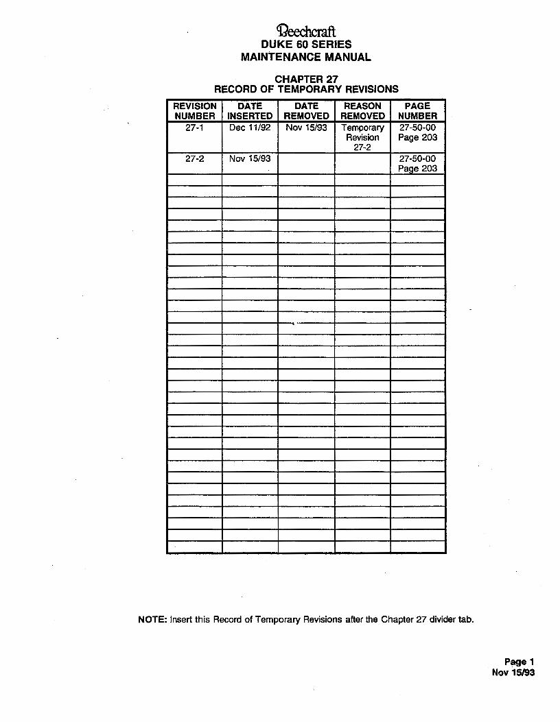
DUKE 60 SERIESMAINTENANCE MANUAL
CHAPTER 2"RECORD OF TEMPORARY REVISIOhS
REVISION DATE DATE REASON PAGENUMBER INSERTED REMOVED REMOVED NUMBER
27-1 Dec 11/92 Nov 15/93 Temporary 27-50-00Revision Page 203
27-227-2 Nov 15/93 27-50-00
Page 203
NOTE: Insert this Record of Temporary Revisions after the Chapter 27 divider tab.
Page 1Nov 15/93

BEECHCRAFTDUKE60 SERIES
MAINTENANCEMANUAL
CHAPTER 27
L/ST OF PAGE EFFECTIVITY
CHAPTERSECTIONSUBJECT PAGE DIATE
27-EFFECTIVITY 1 Sep 20/85
27-CONTENTS 1 Sep 20/852 Sep 20/85
27-00-00 1 Nov 2/73201 Nov 2/73202 Nov 2/73
27-10-00 201 Nov 2/73202 Nov 2/73203 Sep 14/79204 Sep 14/79205 - Sep 14/79
27-20-00 201 Nov 2/73202 Nov 2/73203 Nov 2/73204 Sep 14/79205 Sep 14/79
27-30-00 201 Sep 20/85202 May 30/75203 Sep 20/85204 Sep 20/85204A Sep 20/85205 Sep 14/79206 Sep 14/79207 Sep 14/79
27-50-00 1 Nov 2/73201 Nov 2/73202 Nov 2/73203 Nov 2/73
27-60-00 1 Nov 2/73101 Nov 2/73201 Nov 2/73
27-70-00¯
201 Nov 2/73
"END"
27-EFFECTIVITYPage i
A16 Sep 20/85
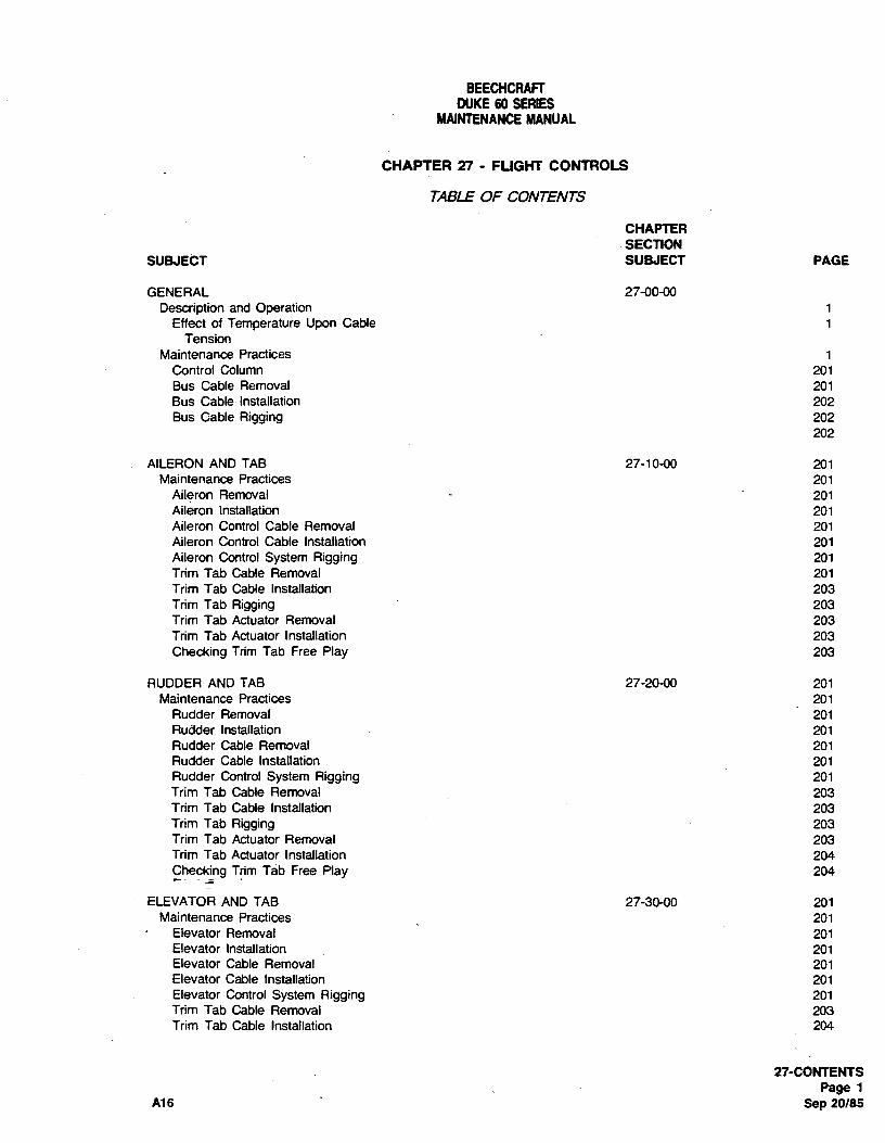
BEECHCRAFTDUKE60 SERIES
MAINTENANCEMANUAL
CHAPTER 27 - FLIGHT CONTROLS
TABLE OF CONTENTS
CHAPTERSECTION
SUBJECT SUBJECT PAGE
GENERAL 27-00-00Description and Operation 1
Effect of Temperature Upon Cable 1Tension
Maintenance Practices 1Control Column 201Bus Cable Removal 201Bus Cable Installation 202Bus Cable Rigging 202
202
AILERON AND TAB 27-10-00 201Maintenance Practices 201
Aileron Removal 201Aileron Installation 201Aileron Control Cable Removal 201Aileron Control Cable Installation 201Aileron Control System Rigging 201Trim Tab Cable Removal 201Trim Tab Cable Installation 203Trim Tab Rigging 203Trim Tab Actuator Removal 203Trim Tab Actuator Installation 203Checking Trim Tab Free Play 203
RUDDER AND TAB 27-20-00 201Maintenance Practices 201
Rudder Removal 201Rudder Installation 201Rudder Cable Removal 201Rudder Cable Installation 201Rudder Control System Rigging 201Trim Tab Cable Removal 203Trim Tab Cable Installation 203Trim Tab Rigging 203Trim Tab Actuator Removal 203Trim Tab Actuator Installation 204Checking Trim Tab Free Play 204
ELEVATOR AND TAB 27-30-00 201Maintenance Practices 201
Elevator Removal 201Elevator Installation 201Elevator Cable Removal 201Elevator Cable Installation 201Elevator Control System Rigging 201Trim Tab Cable Removal 203Trim Tab Cable Installation 204
27-CONTENTSPage 1
A16 Sep 20/85

BEECHCRAFTDUKE60 SERIES
MAINTENANCEMANUAL
CHAPTER 27 - FLIGHT CONTROLS
TABLE OF CONTENTS(Cont'd)
CHAPTERSECTION
SUBJECT SUBJECT PAGE
ELEVATOR AND TAB 27-30-00Maintenance Practices (Cont'd)
Trim Tab Rigging 204Trim Tab Actuator Removal 204ATrim Tab Actuator Installation 204AElectric Trim Tab Actuator Removal 204AElectric Trim Tab Actuator Installation 204AElectric Trim Tab Cable Installation 204AElectric Trim Tab Actuator Magnetic
Clutch Removal 205Electric Trim Tab Actuator Magnetic
Clutch Installation 205Electric Trim Tab Actuator Magnetic
Clutch Torque Test 205Checking Trim Tab Free Play 206
FLAPS 27-50-00 1Description and Operation 1Maintenance Practices 201
Flap Removal 201Flap Installation 201Flap Track Roller Installation 201Control System Rigging 201Functional Ground Test 201Position Transmitter Adjustment
(P-4 through P-246) 201Position indicator Lights -
Adjustment and FunctionalTest (P-247 and after) 203
Actuator Removal 203Actuator Installation 203Motor/Gearbox Removal 203Motor/Gearbox installation 203
STALL WARNING SYSTEM 27-60-00 1Description and Operation iTroubleshooting 101Maintenance Practices 201
Stall Waming InŠcator Removat 201Stall Warning Indicator Installation 201Stall Warning Indicating System Adjustment 201
GUST LOCK 27-70-00 201Maintenance Practices 201
"END"
27-CONTENTSPage 2Sep 20/85 A16

BEECHCRAFTDUKE60 SERIES
MAINTENANCEMANUAL
GENERAL - DESCRIPTION AND OPERATION hand threaded cable end. Cable routing off the pedestal,control column and actuator drums is shown in Figure 201
The flight controls, with the exception of the flaps, are of 27-10-00, 27-20-00, and 27-30-00.conventional cable operated surfaces requiring no powerassistance for normal control by the pilot or copilot. The EFFECT OF TEMPERA TURE UPON CABLEaileron, elevator, and rudder have cable operated flight TENS/ONadjustable trim tabs. The flaps have electrically poweredactuators controlled by a switch on the subpanel. Graphs specifying the correct maximum and minimum
cable tension permissible for the various controls appear onPositive stops on the control surface bell cranks limit their the individual rigging control system illustrations. Thetravel, while travel stops secured on the tab cables limit the graphs provide rigging limits at temperatures varying fromtrim tab movement.
30°to
110°F. The horizontal scale on the graphs designatesthe temperature in degrees fahrenheit at which the control
Since the control cables can be disconnected at the cables may be rigged, and the vertical scale designates theturnbuckles, each cable has one right hand and one left correct tension in pounds for each temperature reading.
"END"
274)0-00Page 1
Nov 2/73

BEECHCRAFTDUKE60SERIES
MAINTENANCEMANUAL
GENERAL - MAINTENANCE PRACTICES regarding chain and cable tension, control wheel movementand force, and system friction. Any time the control
CONTROL COLUMN column has been removed and disassembled, the following(Figure 201)
Refer to the applicable rigging procedures for details
15
14
13
60-155.
1. Wheel 9. Collar2. Collar Assembly 10. Coltar Assembly3. Column Torque Tube 11. Elevator Push Rod4. Elevator Torque Arm 12. Connector5. Elevator Torque Tube 13. Inner Column6. Elevator Bell Crank 14. Sprocket7. Elevator Torque Tube Support 15. Bearing Support .8. Bob Weight Assembly 16. Chain
Control ColumnFigure 201
27-0040Page 201Nov 2/73
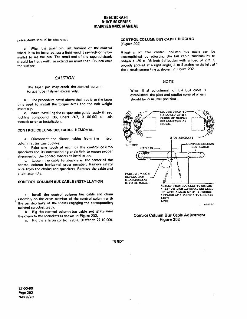
BEECHCRAFTDUKE60SERIES
MAINTENANCEMANUAL
precautions should be observed: CONTROL COLUMN BUS CABLE RIGGING(Figure 202)
a. When the taper pin just forward of the controlwheel is to be installed, use a light weight rawhide or nylon Rigging of the control column bus cable can bemallet to set the pin. The small end of the tapered shank accomplished by adjusting the bus cable turnbuckles toshould be flush with, or extend no more than .06 inch over obtain a .25 ± ,05 inch deflection with a load of 2 ± .5
the surface. pounds applied at a right angle, 4 to 5 inches to the left of '
the aircraft center line as shown in Figure 202.
CAUTIONNOTE
The taper pin may crack the control columntorque tube if driven excessively. When final adjustment of the bus cable is
established, the pilot and copilot control wheelsb. The procedure noted above shall apply to the taper should be in neutral position.
pins used to instalt the torque arms and the bob weightassembly.
c. When installing the torque tube guide, apply thread SECURE CHAIN TO ¯ 'locking compound (36, Chart 207, 91-00-00) t< olt M - --
threads prior to installation. C32 LOCKWIRE ASSHOWN.
CONTROL COLUMN BUS CABLE REMOVAL_ _
\
a. Disconnect the aileron cables from the strol C ( OF AIRCRAFTcolumn at the turn buckles.
LH SIDE CONTROL COLUMNb. Paint one tooth of each of the control column 4 TO 5 IN. --
BUS CABLEsprockets and its corresponding chain link to ensure properalignment of the control wheels at installation.
c. Loosen the cable turnbuckle in the center of the -
--
control column horizontal cross member. Aemove safetywire from the chains and sprockets. Remove the cable andchain assembly. POINT AT WHICH
DEFLECTION
CONTROL COLUMN BUS CABLE INSTALLATION MEASUREMENTIS TO BE MADE.
ADJUST TURN BUCKLES TO OBTAINA .2S*
.05 INCH LATERAL DEFLECT-ION WITH A LOAD OF 2*
.5 POUNDSa. Install the control column bus cable and chain APPLIED AT A POINT 4 TO 5 INCHESassembly on the cross member of the control column with LEFTthe painted links of the chains engaging the corresponding
60-155-1painted sprocket teeth.
b. Rig the control column bus cable and safety wirethe chain to the sprockets as shown in Figure 202. Control Column Bus Cable Adjustment
c. Rig the aiferon control cable. (Refer to 27-10-00). Figure 202
"END"
274)O-00Page 202Nov 2/73

BEECHCRAFTDUKE60 SERIES
MAINTENANCEMANUAL
left side of the pedestal. travel. This will place the actuator in the neutral position.c. Remove the forward left passenger seat and the d. If the trimtab is not in the neutral position upon
floorboard. completion of step "c", adjust push rod to place tab ind. Remove the necessary access plates to gain neutral position.
access to the trimtab cables, the actuator, and the cable e. Center the chain on the sprocket and tighten thepulley brackets. cable. Rig cable tension and adjust travel as noted on the
e. Remove the cable retaining pins at the pulley Aileron Tab Rigging Illustration (Figure 201).brackets. f. Check trim tab travel, adjust cable stops and
f. Disconnect the tab cables at the turnbuckles in safety turnbuckles.the left wing. Identify and connect lead lines on the cableends.
g. Remove the cable stops and the pressure seals. NOTEh. Remove the outboard cable from the actuator
sprocket. Remove the cable through the actuator access After rigging the aileron and aileron tab controlopening. system, check for correct movement of the
i. Remove one chain link at the sprocket on the control surfaces with respect to the movementpedestal.. Remove the cable through the pilot's of the controls.compartment.
AILERON TR/M TAB CABLE INSTALLAT/ON Since the alleron tab is an anti-servo tab, every time thealleron moves up the tab should move up.
a. Position the chain of the forward tab cable aroundthe pedestal sprocket and instalt the chain link. A/LERON TR/M TAB ACTUATOR REMOVAL
b. Route the cable ends aft in the fuselage andoutboard into the left wing. a. Remove the access plates at the actuator and tab
c. Position the chain of the outboard cable around cable tumbuckles.the actuator sprocket and route the cable ends inboard. b. Disconnect the outboard cable at the tumbuckles
d. Install the cable stops and connect the cables at in the wing.the tumbuckles in the wing. c. Remove the outboard cable from the actuator
e. Install all cable retaining pins in the pulley sprocket.brackets. d. Disconnect the actuator from the trimtab linkage.
f. Using PD680 solvent (15, Chart 207, 91-00-00), e. Remove the bolts attaching the actuator to theclean the cables for the length oftravel throughthe pressure wing structure. Remove the actuator.seals. Lubricate to one inch beyond the cleaned area withMIL-G-23827 grease (11, Chart 207, 91-00-00).
g. Fill the pressure seals with MIL-G-23827 grease A/LERON TR/M TAB ACTUATOR INSTALLAT/0N(11, Chart 207, 91-00-00). Install the seals.
h. Rig the aiteron trim tab control system. a. Position the actuator against the wing structurei. Install all access plates in the left wing. and install the attaching bolts.j. Install the floorboard and the left forward b. Connect the actuator to the tab linkage.
passenger seat. c. Install the outboard cable on the actuatork. Install the floorboard and the pilot's seat. sprocket.l. Install the upholstery panel on the left side of the d. Connect the cables at the turnbucklesin the wing.
pedestal. e. Rig the aileron trim tab control system.f. Install the access plates at the actuator and the
tab cable turnbuckles.AIL,ERON TR/M TAB R/GGING(Figure TO1)
CHECKING A/LERON TAB FREE PLAYa. Place cockpit aileron trim tab control in neutral
position. Visually inspect the left aileron tab for damaige, security ofb. Place aileron in neutral position and connect trim hinge attach points, and for tightness of the actuating
tab to tab actuator. system. Inconsistancies should be corrected prior toc. By turningthe sprocketon the actuator, adjust the checking the free play of the tab. The alteron tab free play
trim tab to both extremes of travel;measure both settings check should be performed at least once a year to ensureand return the tab to the mid-point of the two extremes of that the trim tab free play falls within the prescribed limits.
27-1040Page 203
Sep 14/79

BEECHCRAFTDUKE60 SERIES
MAINTENANCEMANUAL
A check fixture (P/N 45-135030-9/810) or the equivalent as 3. Multiply "D" by 2 and record as "2D".shown in Figtire 202, a dial indicator, and a push-pull scalefor applying accurate loading to the tab is required for 4. Subtract "C" from "2D" and record as "Y".making the inspection for free play of the tab.
a. Securely lock the control surfaces to prevent NOTErnovement of the ailerons. Set the allerontab in the neutralposition. The results of "X" and "Y" can be negative
b. Using shot bags, affix the dial indicator check numbers.fixture so that the dial indicator point is 2.30 inches aft of thetab hinge line and on the outboard edge of the aileron tab.
c. Apply a small piece of masking tape (for paint 5. Add "X" and "Y" and record as "E".protection) 4.00 inches aft of the tab hinge line and alongthe centerline of the tab actuator. This will be the point ofpressure against the tab by the push-pull scale.
d, Apply another piece of masking tape in the CHART 201côrresponding position on the bottom surface of the tab for AILERON TAB FREE PLAY LIMITSihe same purpose.
e. Zero the dial indicator at no load initially. Do not 1.5-POUND 3-POUNDreset during the checking procedure. READING READING
f. With the push-pull scale at the point of maskingtape, apply a full 3-pound downward load. Record the dial Breading as "A". 28 -A =X
g. Release half the load until a 1.5-pound downward ·
load is obtained. Record the dial reading as "B". Dh. Apply a full 3-pound upward load at the masking 2D -C = Y
tape on the bottom surface. Record the dial reading as "C".i. Release half the load until a 1.5-pound upward X +Y = E
load is obtained. Record the dial reading as "D".j. Enter the recorded values on a copy of Chart 201 (E = 0.032 inch maximum)
and proceed as follows:k. If the aileron trimtab free play exceeds the 0.032
1. Multiply "B" by 2 and record as "2B". inch maximum noted above, inspect all components of thetab actuation system to determine the cause. Allwom parts
2. Subtract "A" froin "28" and record as "X". should be replaced.
27-10-00Page 204Sep 14/79

BEECHCRAFTOUKE60 SERIES
MAINTENANCEMANUAL
10 1213 6 7 8
11
.81N -----------------------------------
.SIN
4AA
TAB
314 -15
2· -1.30 IN 7 IN -
ITEM QUANT. DESCRIPTIONNO.
1 2 3/4 x 1 x 6 aluminum or equiv.2 2 1 x 1 3/8 x 1 3/4 aluminum or equiv. .68 IN ...-
3 1 1/2 x 7 1/2 x 10 aluminum or equiv.4 1 CB1Q Indicator"5 1 3/4 x 2 1/2 x 14 aluminum or equiv.6 1 1/4 Dia. x 2 corrosion res. sti- 1.6 IN7 1 1/4 Dia. x 1 corrosion res. sti.8 1 1/4-28 nut .31
IN--•
9 1 3/8 x 5 x 10 rubber10 1 3/8 x 2 x 10 rubber11 1 1/4 x 2 x 10 corrosion res. stl.12 2 1/2 x 13 x 3 VLIER Torque screw13 - 2 KN813 Keensert or tap 1/2 - 13
SECTION A A14 2 1/8 x 1 x 3/4 rubber* THIS GROOVE TO BE A SNUG FIT
TO THE SCREW BRACKET ON"P/N of Federal Products Corp., Providence, R.I· THE DIAL INDICATOR
100-135-8
(P/N 45-135030-9/810) Check Fixture for Tab DeflectionFigure 202
"END"
27-10-00
Page 205
Sep 14/79

BEECHCRAFTDUKE60 SERIES
MAINTENANCEMANUAL
RH horizontal stabilizer, and the access panel in the aft e. Route the forward cable end aft and install all
floorboard, cable retaining pins in the pulley brackets.f. Using PD680 solvent (15, Chart 207, 91-00-00),
RUDDER TRIM TAB CABLE REMOVAL clean the cables for the length of travel through the pressure(Figure 201) seals. Lubricate to one inch beyond the cleaned area with
MIL-G-23827 grease (11, chart 207, 91-00-00).a. Remove the tail cone, the access plate beneath the g. Fill the pressure seals with MIL-G-23827 grease
RH horizontal stabilizer, and the access plate at the trim (11, Chart 207, 91-00-00). Install the seals.tab actuator. h. Install the cable stops and connect the cables to
b. Remove the pilot's seat and the left floorboard- the turnbuckles in the aft fuselage. Rig the rudder trim tabc. Remove both upholstery panels on the left side of control system.
the pedestal. i. Install the access panel in the floorboard aft of thed. Remove the left passenger seat, the floorboard rear spar, the floorboard between the main and rear spar,
between the main and rear spar, and the access panel in the and the left passenger seat.floorboard aft of the rear spar. j. Install both upholstery panels on the left side of
e. Remove the cable retaining pins from the pulleV the pedestal.brackets and the pressure seals from the rear pressure k. Install the left floorboard and the pilot's seat.bulkhead. . 1. Install the tail cone, the access plate beneath the
f. Disconnect the trim tab cables, in the aft fuselage, RH horizontal stabilizer and the access plate at the trimat the turnbuckles and connect lead lines to the forward tab actuator.cables. Identify the lead line for tab left and tab right
movement to ensure proper cable rerouting. RUDDER TR/M TAB R/GGINGg. Remove the taper pin from the forward universal
and remove the attaching shaft and cable reel. Note and a. Disconnect the tab from its acfuator.record the number of cable revolutions on the reel- b. Position the rudder in neutral and set the tab
h. Remove the forward trim tab cable through the indicator at zero degrees.pilot's compartment. c. Rig the tab cables to the proper tension as
i. Remove the tab cable stops and disconnect the determined by the Temperatuæ-Cable Tension Chart.chain and cable assembly at the trim tab actuator. Remove Safety wire the turnbuckles.the aft cable chain and cable assemblY- d. Position the tab actuator screw at the midpoint of
its travel.RUDDER TRIM TAB CABLE INSTALLATION e. Adjust the actuator linkage until the tab is in the(Figure 201) neutral position with the chain centered on the actuator
sprocket and connect the tab to the actuator.a. With the rudder tab in neutral, position the aft f. Adjust the cable stops until the rudder tab has a
chain and cable assembly on the trim tab actuator sprocket travet of 19 to 21 degrees to both the left and right.so that the ends of the chain are equi-distant at the g. Torque the cable stops to 40 to 60 inch-poundssprocket centerline within ±
.20 inch- and safety.b.. Route the aft chain and cable assembly forward in h. Check the tab control and tab surface for correct
the aft fuselage. movement as indicated by the tab indicator. When the tabc. Place the rudder trim tab control wheel in neutral control is moved to the left, the tab should move to the
position and wrap the forward cable around the reel the right.same number of revolutions noted during removal, i. Check the rudder trim tab control system formaintainingthecableendsequi-distant- friction at the tab control wheel shaft. At room
d. Install the attaching shaft, washer and reel; align temperature, the maximum allowable torque limit is 12the shaft with the forward universal and install the taper inch-pounds.pin.
RUDDER TRIM TAB ACTUATOR REMOVALNOTE
a. Remove the access plate at the trim tab actuator.. When the trim tab control cable is disconnected b. Remove the tail cone and the access plate beneath
at the pedestal, the tab wheel shall turn the RH horizontal stabilizer.smoothly with very little resistance. Bearings c. Remove the access panel in the floorboard aft ofnot previously lubricated may be tubricated the rear spar.with MIL-L-6086 lubricating oil (7, Chart 207, d. Disconnect the tab control cables at the91-00-00). Lubricate shafts and thrust surfaces turnbuckles in the aft fuselage.in all trim tab systems with MIL-G-23827 e. Disconnect the tab actuator at the tab.grease (11, Chart 207, 91-00-00) for friction f. Remove the aft chain and cable assembly from thereduction. actuator sprocket.
27-20-00Page 203Nov 2/73

BEECHCRAFTDUKE60 SERIES
MAINTENANCEMANUAL
g. Remove the bolt attaching the actuator to the f. With the push-pull scale at the point of maskingactuator hinge. Remove the actuator. tape, apply a full 3-pound load to the right. Record the dial
reading as "A".g. Release half the load until a 1.5-pound load is
RUDDER TR/M TAB ACTUATOR INSTALLATION obtained. Record the dial reading as "B".h. Apply a full 3-pound load at the masking tape on
a. Position the tab actuator on the actuator hinge the opposite surface. Record the dial reading as "C".and install the attaching bolt, i. Release half the load until a 1.5-pound load is
b. Connect the actuator at the tab. obtained. Record the dial reading as "D".c. With the rudder tab in neutral, position the aft
,j. Enter the recorded values on a copy of Chart 201
chain and cable assembly on the actuator sprocket so that and proceed as follows:the ends of the chain are equi-distant at the sprocketcenterline within ± .20 inch, 1. Multiply "B" by 2 and record as "28".
d. Connect the tab control cables to the turnbucklesin the aft fuselage. 2. Subtract "A" from "2B" and record as "X".
e. Rig the rudder tab control system.f. Install the access panel in the floor board aft of 3. Multiply "D" by 2 and record as "2D".
the rear spar.g. Install the tail cone and the access plate beneath 4. Subtract "C" from "2D" and record as "Y".
the RH horizontal stabilizer.h. Install the access plate at the trim tab actuator.
NOTE
CHECKINGRUDDER TAB FREE PLAY The results of "X" and "Y" can be negativenumbers.
Visually inspect the rudder tab for damage, security of hingeattach points, and for tightness of the actuating system.Inconsistancies should be corrected prior to checking the 5. Add "X" and "Y" and record as "E".free play of the tab. The rudder tab free play check shouldbe performed at least once a year to ensure that the trimtabfree play falls within the prescribed limits.
CHART 201A check fixture (PIN 45-135030-9/810) or the equivalent as RUDDER TAB FREE PLAY LIMITSshown in Figure 202, a dial indicator, and a push-pull scalefor applying accurate loading to the tab is required for 1.5 POUND 3-POUNOmaking the inspection for free play of the tab. READING READING
a. Securety lock the control surface to prevent 8movement of the rudder. Set the rudder tab in the neutral 2B - A = Xposition.
b. Tape the dial indicator check fixture to the rudder Dso that the dial indicator point is positioned 8.70 inches aft 2D -C =Yof the tab hinge line and at the top edge of the tab.
c. Apply a small piece of masking tape (for paint X + Y = Eprotection) 9.0 inches aft of the tab hinge line and along thecenterline of the tab actuator. This will be the point of (E = 0.061 inch maximum)pressure against _the tab by the push-pull scale.
d. Appl¶ ariofher þiece of masking tape in thecorresponding position on the opposite side for the same k. If the rudder trim tab free play exceeds the 0.061purpose. inch maximum noted above, inspect all components of the
e. Zero the dial indicator at no load initially. Do not tab actuation system to determine the cause. All wom partsreset during the checking procedure. should be replaced.
27-2O•OOPage 204Sep 14/79
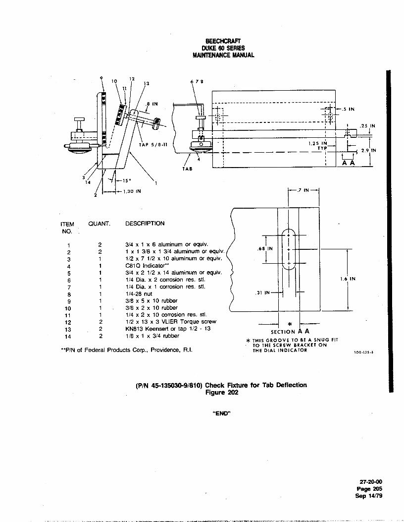
BEECHCRAFTDUKE60 SERIES
MAINTENANCEMANUAL
10 1213 6 7 8
11
.8 IN ----------- -------------------- --
.25 IN
(-1 TA P 5 / 8 -11 1.
N
A ATAB '
14 7 -15°
2x -- - 1.30 IN .7 N --
ITEM QUANT. DESCRIPTIONNO.
1 2 3/4 x 1 x 6 aluminum or equiv,2 2 1 x 1 3/8 x 1 3/4 aluminum or equiv. .68 IN --
3 1 1/2 x 7 1/2 x 10 aluminum or equiv.4 1 CB1Q Indicator** - ¯
5 1 3/4 x 2 1/2 x 14 aluminum or equiv.6 1 1/4 Dia. x 2 corrosion res. stl. 1.6 IN7 1 1/4 Dia. x 1 corrosion res. sti.8 1 1/4-28 nUt .31
IN---• •-
9 1 3/8 x 5 x 10 rubber10 1 3/8 x 2 x 10 rubber11 1 1/4 x 2 x 10 corrosion res. stl.12 2 1/2 x 13 x 3 VLIER Torque screw13 . 2 KN813 Keensert or tap 1/2 - 13
SEx:TION A A14 2 1/8 x 1 x 3/4 rubber
* THIS GROOVE TO BE A SNUG FITTO THE SCREW BRACKET ON**P/N of Federal Products Corp., Providence, R.I- THE DIAL INDICATOR
(P/N 45-135030-9/810) Check Fixture for Tab DeflectionFigure 202
"END"
27-20-00
Page 205Sep 14/79

BEECHCRAFTDUKE60 SERIES
MAINTENANCEMANUAL
I NOTE e. On airplane serials prior to P-438, insert a 1/4 inchdiameter rig pin in the control lock pin hole in the control
To position the elevator in neutral on airplane column. Insert a 3/16 inch diameter rig pin in the aft elevatorserials P-438 and after, fabricate a tool from 5/16 bell crank and adjacent structure.inch diameter steel rod as shown in Figure 201A. f. To set the elevator controls in neutral on airplane
serials P-438 and after, insert the short end of the fabricateda. Remove the tail cone and the access plate on tNe tool (see Figure 201A)in the control column hanger. Move the
side of the fuselage beneath the RH horizontal stabilizer, control aft and insert the other end of the tool into the controlb. Position the aft elevator bell crank in neutral by shaft and torque tube. Insert a 3/16inch diameter rig pin in the
inserting a 3/16 inch diameter rig pin through the bell crank aft elevator bell crank and adjacent structure.and adjacent structure. 9- With the rig pins and elevator down springs
c. Adjust the elevator push rods to place the elevator installed, rig the elevator cable tension as noted on thein neutral. Elevator Rigging Illustration, Figure 201.
h. Remove the rig pins, securely tightenall lock nutsand safety wire the turnbuckles.
NOTE
After the push rods are adjusted, the threads on NOTEthe rod ends must be visible in the inspectionholes at each end of the push rods. With the system fully installed (including the
autopilot when installed) measure the forcerequired to move the control column from the
d. Remove the rig pin from the aft elevator bell crank full forward position through neutral with a handand adjust the elevator travel stops to obtain 17°
± 1° up force gage. This force should measure betweentravel and 15° ± 1° down travel. 32 and 36 pounds. The force required to
restrain the control column when passingthrough neutral from a position not rnore thanone inch aft of neutral should measure between16 and 20 pounds when the system is properly
FABRICATEFROM 5/16-tNCH DIAMETER STEEL AOD rigged.
1.35" NOTE
After rigging the elevatorand elevator tab controli system, check for correct movement of thecontrol
surfaces with respect to the movement of thecontrols. When the elevator trimtab control wheelis moved toward the NOSE DOWN position, the
2.20. elevator tab should move URI
i. Install the tail cone and the access plate on theside of the fuselage beneath the RH horizontal stabilizer.
as- ELEVATOR TR/M TAB CABLE REMOVAL(Rgure 20 i)
60-17-15
a. Remove the tail cone, the access plate beneaththe RH horizontal stabilizer, and the access plate at the trimtab actuator.
Elevator Neutral Rigging Tool b. Remove the pilot's seat and the left floorboard.(P-438 and after) c. Remove both upholstery panels on the left side of
Figure 201A the pedestal.
27-3600Page 203
A16 Sep 20/85

BEECHCRAFTDUKE60 SERIES
MAINTENANCEMANUAL
d. Remove the left passenger seat, the floorboard f. Using PD680 solvent (15, Chart 207, 91-00-00),between the main and rear spar, and the access panel in clean the cables for the length of travelthrough the pressurethe floorboard aft of the rear spar. seals. Lubricate to one inch beyond the cleaned area with
e. Remove the cable retaining pins from the pulley MIL-G-23827 grease (11, Chart 207, 91 -00).
brackets and the pressure seals from the rear pressure g. Fill the pressure seals with MIL-G-23827 greasebulkhead. (11, Chart 207, 91-00-00). Install the seals.
f. Disconnect the trimtab cables, in the aft fuselage, h. Install the cable stops and connect the cables toat the turnbuckles. Identify the cable for tab up movement the turnbuckles in the aft fuselage. Rig the elevator trim taband connect lead lines to the cables. control system.
g. Remove the pressure seals in the rear pressurebuikhead. NOTE
h. Remove the tab cable stops and disconnect thechain and cable assembly at the trimtab actuator. Remove The force in line with the elevator tab cables re-the aft cable and chain assembly. quired to move the cable shall not exceed 23
i. Remove the bolt attaching the cable drum and pounds measured with a hand held force gage,sprocket to the lower pedestal. Note and record the number with or without electric trim.of cable revolutions on the reel.
j. Remove the cable through the pilot's .i. Instalt the access panel in the floorboard att of thecompartment. rear spar, the floorboard between the main and aft spar, and
the left passenger seat.j. Install the left floorboard and the pilot's seat.
ELEVATOR TR/M TAB CABLE INSTALLATION k. Install both upholstery panels on the pedestal.(Figure 201) I. Install the tail cone, the access plate beneath the
Ri÷horizontal stabilizer, and the access plate at the trim tab. a. Place the elevator trimtab control wheel in neutrai actuator.
position and wrap the cable around the drum the samenumber of revolutions noted during removal, maintaining thecable ends equidistant. ELEVATOR TR/M TAB R/GGING
b. Position the cable drum and sprocket in the lowerpedestal, with the chain and sprocket teeth engaged, andinstall the attaching bolt. Route the forward cable aft to theLH trim cable pulley located in the lower fuselage area. NOTERoute the aft cable aft to the RH trimcable pulley located inthe lower fuselage area. BEECHCRAFT recommends the use of the eleva-
tor travel gage shown in SPECIAL TOOLS inChapter 12-20-00.
NOTE
When the trim tab control cable is disconnectedat the pedestal, the tab wheel shall turnsmoothly with very little resistance. Bearings not a. Place the elevator trim tab control in neutralpreviously tubricated may be lubricated with position.MIL-L-6086 oil (7, Chart 207, 91-00-00). b. Place the elevator in neutral position and connectLubricate shafts and thrust surfaces with MIL-G- the trim tab to the trim tab actuator.23827 grease (11, Chart 207, 91-00-00) for c. By turningthe sprocket on the actuator, adjust thefriction reduction. trim tab to both extremes of travel; measure both settings
and return the tab to the mid-point of the two extremes oftravel. This will place the actuator in the neutral position.
c. With the elevator tab in neutral, position the aft d. If the trimtab is not in the neutral position uponcable and chain assembly on the trim tab actuator sprocket completion of step "c.", adjust the actuator push rod toso that the ends of the chain are equidistant at the sprocket place the tab in neutral position.centerline within ± .20 inch. e. Center the chain on the sprocket and tighten the
d. Route the chain and cable assembly inboard and cable. Rig cable tension as noted on the Elevator Riggingforward in the aft fuselage. Illustre on, Figure 201.
e. Install all cable retaining pins in the pulley f Check trim tab travel, adjust stops and safetybrackets. turnbu es.
27-30-00Page 204Sep 20/85 A16
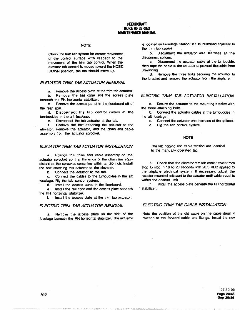
BEECHCRAFTDUKE60 SERIES
MAINTENANCEMANUAL
NOTE is located on Fuselage Station 311.19 bulkhead adjacent tothe trim tab cables.
Check the trim tab system for correct movement b. Disconnect the actuator wire harness at theof the control surface with respect to the disconnect splices,movement of the trim tab control. When the c. Disconnect the actuator cable at the tumbuckle,elevator tab control is moved toward the NOSE then tape the cable to the actuator to prevent the cable fromDOWN position, the tab should move up. unwinding.
d. Remove the three bolts securing the actuator tothe bracket and remove the actuator from the airplane.
ELEVATOR TRIM TAB ACTUATOR REMOVAL
a. Remove the access plate at the trim tab actuator.b. Remove the tail cone and the access plate ELECTRIC TRIM TAB ACTUATOR INSTALLATION
beneath the RH horizontal stabilizer.c. Remove the access panel in the floorboard aft of a. Secure the actuator to the mounting bracket with
the rear spar. the three attaching bolts.d. Disconnect the tab control cables at the b. Connect the actuator cables at the tumbuckles in
turnbuckles in the aft fuselage. the aft fuselage.e. Disconnect the tab actuator at the tab. c. Connect the actuator wire harness at the splices.f. Remove the bolt attaching the actuator to the d. Rig the tab control system.
elevator. Remove the actuator, and the chain and cableassembly from the actuator sprocket.
NOTE
ELEVA TOR TRIM TAB ACTUATOR INSTALLAT/ON The tab rigging and cable tension are identicalto the manually operated tab.
a. Position the chain and cable assembly on theactuator sprocket so that the ends of the chain are equi-distant at the sprocket centerline within ± .20 inch. Install e. Check that the elevator trimtab cable travels fromthe bolt attaching the actuator to the elevator. stop to stop in 18 to 20 seconds with 28.5 VDCapplied to
b. Connect the actuator to the tab. the airplane electrical system. If necessary, adjust thec. Connect the cables to the tumbuckles in the aft resistor mounted adjacent to the actuator until cable travel is
fuselage. Rig the tab control system. within the desired limit.d. Install the access panel in the floorboard. f. Install the access plate beneath the RH horizontale. Install the tail cone and the access plate beneath stabilizer.
the RH horizontal stabilizer.f. Install the access plate at the trim tab actuator.
ELECTRIC TR/M TAB ACTUATOR REMOVAL ELECTRIC TR/M TAB CABLE INSTALLATION
a. Remove the access plate on the side of the Note the position of the old cable on the cable drum infuselage beneath the RH horizontal stabilizer.The actuator relation to the forward cable end fittings. Install the new
27-30-00A16 Page 204A
Sep 20/85
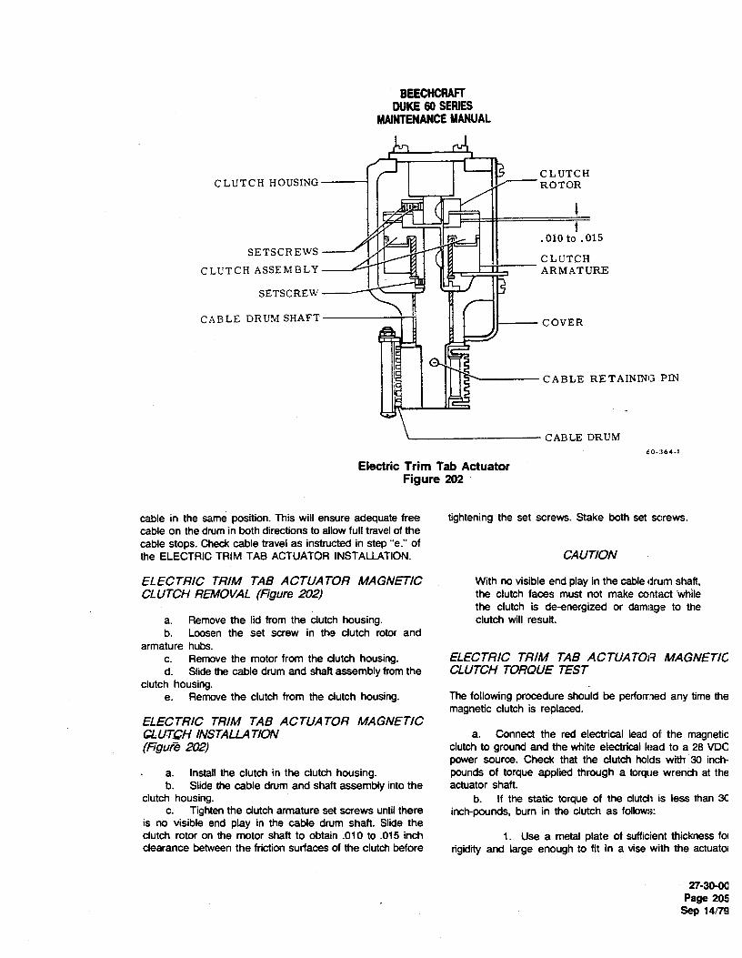
BEECHCRAFTDUKE60 SERIES
MAINTENANCEMANUAL
CLUTCH HOUSING CLUTCHROTOR
.010 to .015
SETSCREWS
CLUTCH ASSEMBLY CLUTCHARMATURE
SETSCREW
CABLE DRUM SHAFT----- COVER
CABLE RETAINING PIN
CABLE DRUM60-364-1
Electric Trim Tab ActuatorFigure 202
cable in the same position. This will ensure adequate free tightening the set screws. Stake both set screws.cable on the drum in both directions to allow full travelof thecable stops. Check cable travel as instructed in step "e." ofthe ELECTRIC TRIM TAB ACTUATOR INSTALLATION. CAUTION
ELECTRIC TRIM TAB ACTUA TOR MAGNETIC With no visible end play in the cabledrum shaft,CLUTCH REMOVAL (Figure 202) the clutch faces must not make contact while
the clutch is de-energized or damage to thea. Remove the lid from the clutch housing. clutch will result.b. Loosen the set screw in the clutch rotor and
armature hubs.c. Remove the motor from the clutch housing. ELECTRIC TRIM TAB ACTUATOR MAGNETICd. Slide the cable drum and shaft assembly from the CLUTCH TOROUE TEST
clutch housing.e. Remove the clutch from the clutch housíng. The following procedure should be performed any time the
magnetic clutch is replaced.ELECTRIC TRIM TAB ACTUATOR MAGNETICGLUTOH INSTALLAT/ON a. Connect the red electrical lead of the magnetic(Figura 202) clutch to ground and the white electrical lead to a 28 VDC
power source. Check that the clutch holds with 30 inch-- a. Install the clutch in the clutch housing. pounds of torque applied through a torque wrench at the
b. Slide the cable drum and shaft assembly into the actuator shaft.clutch housing. b. If the static torque of the clutch is less than 30
c. Tighten the clutch armature set screws until there inch-pounds, bum in the clutch as follows:is no visible end play in the cable drum shaft. Slide theclutch rotor on the motor shaft to obtain .010 to .015 inch 1. Use a metal plate of sufficientthickness foiclearance between the friction surfaces of the clutch before rigidity and large enough to fit in a vise with the actuatoi
27-30-00Page 205
Sep 14/79

BEECHCRAFTDUKE80 SERIES
MAINTENANCEMANUAL
assembly attached. Anchor the plate in a vise and mount d. Apply another piece of masking tape in thethe actuator on the plate. corresponding position on the bottom surface of the tab for
2. Insert the retaining pin in the actuator shaft. the same purpose.3. Slot the end of the tube so that it will fit e. Zero the dial indicator at no load initially. Do not
snugly into the .375 inch diameter hole in the end of the reset during the checking procedure.shaft. f. With the push-pull scale at the point of the
4. Insert the tube into the shaft until the slot masking tape, apply a full 3-pound downward load. Recordengages the retaining pins, the dial reading as "A".
5. Attach the free end of the tube to a slow g. Aelease half the load until a 1.5-pound downwardspeed (approximately450 rpm) half-inch drill motor. Ioad is obtained. Record the dial reading as "B".
6. Remove the access plate from the clutch b. Apply a full 3-pound upward load at the maskinghousing and blow the housing and clutch clean. tape on the bottom surface. Record the dial reading as "C".
7. Connect the red electrical lead of the clutch i. Release half the load until a 1.5-pound upwardto ground and the white electrical lead to a regulated power load is obtained. Record the dial reading as "D".source set at 14 to 16 VDC. j. Enter the recorded values on a copy of Chart201
8. Start the drill motor and run for fifteen and proceed as follows:seconds, then remove the white lead from the powersource. Let the clutch cool for approximately one minute 1. Multiply "B" by 2 and record as "28".before reattaching the lead for another fifteen secondinterval. Repeat the foregoing sequence until the clutch will 2. Subtract "A" from "2B" and record as "X".hold 30 inch-poundsof torque as indicated in step "a", thenblow the clutch and housing clean with compressed air. 3. Multiply "D" by 2 and record as "2D".
4. Subtract "C" from "2D" and record as "Y".CAUTION
Exceeding the fifteen second bum-in periods NOTEmay overheat and damage the magnetic clutch.
The results of "X" and "Y" can be negativenumbers.
CHECKING ELEVATOR TAB FREE PLAY5. Add "X" and "Y" and record as "E".
Visually inspect the elevator tabs for damage, security ofhinge attach points, and for tightness of the actuatingsystem. Inconsistancies should be corrected prior to CHART 201checking the free play ofthe tabs. The elevator tab free play ELEVATOR TAB FREE PLAY LIMITScheck should be performed at least once a year to ensurethat the trimtab free play falls within the prescribed limits. i.S POUND 3-POUND
READING READINGA check fixture (PIN 45-135030-9/810) or the equivalent asshown in Figure 203, a dial indicator, and a push-pull scale Bfor applying accurate loading to the tab is required for 2B -A =Xmaking the inspection for free play of the tab.
Da. Securely lock the control surfaces to prevent 2D -C =Y
movement of the elevators. Set the elevator tabs in theneutral position X + Y = E
b. Using shot bags, affix the dial indicator checkfixture so that the dial indicator point is positioned 2.90 (E = 0.020 inch maximum).inches aft of the tab hinge line and on the outboard edge ofthe elevator tab.
c. Apply a small piece of masking tape (for paint k. If the elevator trimtab free play exceeds the 0.020protection) 4.50 inches aft of the tab hinge line and along inch maximum noted above, inspect all components of thethe centerline of the tab actuator. This will be the point of tab actuation system to determine the cause. AIIworn partspressure against the tab by the push-pull scale. should be replaced.
27-30-00Page 206Sep 14/79

BEECHCRAFTDUKE60 SERIES
MAINTENANCEMANUAL
10 1213 6 7 8
.8 IN ------- ---------- --------------- ---
.5 IIN
.25 IN
C TAP 5/8-11 1.25 1N--
---- - -- --- - 2 .9 IN4
AATAB '
314 -15°
2, --1.30 IN.7 IN -
ITEM QUANT. DESCRIPTIONNO.
1 2 3/4 x 1 x 6 aluminum or equiv.2 2 1 x 1 3/8 x 1 3/4 aluminum or equiv. .68 IN
3 1 1/2 x 7 1/2 x 10 aluminum or equiv.4 1 C81Q Indicator** + -- -
5 1 3/4 x 2 1/2 x 14 aluminum or equiv.6 1 1/4 Dia. x 2 corrosion res. sti 1.6 IN7 1 1/4 Dia. x 1 corrosion res. sti.8 1 1/4-28 nut
.31
tN--- --
9 1 3/8 x 5 x 10 rubber10 1 3/8 x 2 x 10 rubber11 1 1/4 x 2 x 10 corrosion res. sti.12 2 1/2 x 13 x 3 VLIER Torque screw13 2 KN813 Keensert .or tap 1/2 - 1314 2 1/8 x 1 x 3/4 rubber SECTION A A
* THIS GROOVE TO BE A SNUG FITP/N of Federal Products Corp., Providence, R.I. TO THE SCREW BRACKET ON
THE DIAL INDICATOR100-135-8
(P/N 45-135030-9/810) Check Fixture for Tab DeflectionFigure 203
"END"
27-30-00
Page 207Sep 14/79

BEECHCRAFTDUKE60 SERIES
MAINTENANCEMANUAL
FLAPS - DESCRIPTION AND OPERATION position.
The flaps consist of a section on each wing driven by asingle electric motor. A flexible drive shaft extends from On serials P-247 and after, the position of the flaps arethe motor assembly to a jackscrew actuator for each indicated by three indicator lights located on the righisection. Limit switches, installed on the outboard side of subpanel. The illumination of these lights are controlled bythe inboard flap track of the left wing panel, stop the flap the flap limit switches. When the flaps are UP, all lights aretravel at
0°(full up),
15°(approach), and
30° (full down) out. A red TRANSIT light illuminates to indicate that thedepending on the position of the flap control switch flaps are not in the selected position. The red TRANSITfocated to the right of the control console on the subpanel. light goes out and either the blue APH (approach) or the
amber DN (down) light illuminates to indicate the flaps areTo indicate the position of the flaps on serials P4 through in the position selected. The intensity of illumination isP-246, an adjustable flap position transmitter is installed on reduced for night operations when the NAV lights arethe flap actuator in the right wing. An indicator on the turned on. The lights may be checked by pressing theright subpanel provides a visual indication of the flap PRESS-TO-TEST switch on the annunciator panel.
"END"
27-5040Page 1
Nov 2/73

BEECHCRAFTDUKE60 SERIES
MAINTENANCEMANUAL
FLAPS - MAINTENANCE PRACTICES NOTE
FLAP REMO VAL Rig the ffaps under a simulated flight load toreduce overtravel to a minimum after the limit
a. Fully extend the flaps and remove the bolt from switches have been adjusted.the flap actuating arm.
b. Remove the bonding cable from the flap tracks. a. Adjust the up limit switch so the flap will stopc. Remove the bolts from the flap track brackets and approximately 3/32 inch from the forward portion of the
remove the flap. slot on the inboard flap track.b. Adjust the 14°
Iimit (inboard) switch in itsFLAP INSTALLA T/ON mounting slot until the flap is positioned at 14°
to14.5°
after the flap has been actuated from the up to takeoffa. Hold flap in position and instaff the rollers and the position (15°
range). Adjust the16°
Iimit (outboard)bolts in the flap track bracket. switch(es) in its mounting slot until the flap is positioned at
b. Connect the bonding cable and install the bolt in 15.5°to
16° after the flap has been actuated from thethe flap actuating arm. down to takeoff position,
c. Adjust the down limit switch in its mounting slotsuntil it actuates at
28°to
30° of flap travel.NOTE d. Remove the bolt attaching the right actuator to the
right flap.The contour of the flap must be within .0625 e. Turn the jackscrew on the right actuator in or outinch of the contour of the wing on either or to align the right flap with the left.both sides. The inboard trailing edge of the flap f. Install the bolt connecting the actuator to the f1ap.must be within .20 inch above or below thetrailing edge of the wing stub on either ör both CAUTIONsides. The gap between the flap and aileronmust be between .13 and .50 inch. If flaps are removed for any reason the flap
actuator switch should be in the "Neutral"FLAP TRA CK ROLL ER INSTALLA T/ON position or the main power switch OFF.
Install the rollers (four per flap and two per track) in the NOTEflap track brackets with the flanges to the outboard side ofthe inboard track and to the inboard side of the outboard After the flap is completely rigged, adjust thetrack. Install a 50-105000-3 washer between each of the aft rubber bumper (flap down) installed on the flaprollers and its respective track. Use only the wide flanged and aileron dividing rib. Turn the adjustingrollers in the aft locations. The clearance between the roller screw in or out as required to take out play orand the front end of the forward slot in each track must be stop vibration when the flap is in the up.03 to .12 inch. position. A distinct change in sound of the flap
motor near the completion of the flap up travelFLAP CONTROL SYSTEM R/GGING may indicate an excessive outward adjustment(Figure 201) of the bumper.
The flap limit switches are mounted on a bracket and FLAP FUNCTIONAL GROUND TESTinstalled on the outboard side of the inboard flap track inthe left wing panel. The limit switches, one for up, two for a. Connect a ground power unit (regulated at 28.25 ±the approach position, and one for down travel, control the .25 VDC) to the aircraft.travet of the flaps by breaking the circuit to the flap motor b. Check flap motor amperage during down and upat the extreme limits of selected travel. The switches are cycles. (Maximum 7.0 amps down;9.0 amps up.)accessibleiy lowering the flaps. c. If the amperage is exceeded during the up or down
cycle, the system must be inspected for excessive friction,rough flap tracks or misrigging.
NOTE d. Avoid continuous operation of the flaps to preventoverheating of the motor.
An additional 16°Iimit switch is installed on
serials P-247 and after. FLAP POS/TION TRANSMITTER ADJUSTMENT(P-4 through P-246)
The flap travel is adjusted by moving the limit switches. (Figure 201)The left flap is rigged first and then the right flap issynchronized with it. Rig as follows: An adjustable flap position indicator transmitter is installed
27-5040Page 201Nov 2/73

BEECHCRAFTDUKE60 SERIES
MAINTENANCEMANUAL
FLAP SETTINGS FLAP SYSTEM
Approach- 15° from NeutralFull Down- 30°from Neutral
4, Limit Switches
43
FLAP TRANSMITTER AND POSITION INDICATORS
24
TRANSIT UP
APH
3 I DN
TO ADJUST, LOOSEN MOUNTINGBOLTS AND MOVE FORE AND AFT, e- JOR RDTATE SLIGHTLY.
1. Transmitter 3. Indicator
FLAP LIMIT SWITCHES
2. Flap Actuator *4.Indicator Lights
3
1. Down Limit Switch2. Up Limit Switch3. 14° Limit Switch4. 16° Limit Switches
'INDICATOR LIGHTS AND (2)16° LIMIT SWITCHESARE IN-STALLED ON SERIALS P-247AND AFTER.
6 161-1A
Flap SystemFigure 201
27-50-00Page 202Nov 2/73

DUKE 60 SERIESMAINTENANCE MANUAL
TEMPORARY REVISION NO. 27-2Manual Affected: Duke 60 Series Maintenance Manual (60-590001-25)
Filing Instructions: Insert adjacent to 27-50-00, Page 203, dated Nov 2/73.
Reason: Revise procedures for flap drive cable connection.
FLAP DRIVE CABLE CONNECTIONConnect the LH and RH flap drive cables to the flap drive motor as follows, using the illustration for componentlocations:
a. Install the outboard nut and washer as far as it will go on the threaded portion of the flap cable.b. Insert the retainer through the mount support and onto the motor shaft as far as it will go. Align the retainerkeyway with the key slot in the flap motor drive shaft and tighten one set screw temporarily.c. While inserting the flap cable through the mount support, install the inboard washer and nut. Install the cablethrough the retainer and into the motor drive shaft until the keyway is just past the key slot in the retainer.d. Loosen the set screw that was tightened in Step b. Ensure that the retainer is still installed on the motor shaftas far as it will go and rotate the retainer 90°.
e. Keep inboard pressure on the retainer and tighten both retainer set screws.f. ee the flap drive cable to the mounting support by tighteningthe nuts. Tighten the inboard nut to ensurethat is sufficientclearance between the outboard edge of the retainer and the cable housing to allow thereta rotate without coming into contact with the cable housing. If the threaded part of the cable housing isnot L ough to install the two nuts and washers, using a die, add 5/8-24 UNEF threads until .88 inch threadleng ched. Tighten the outboard nut against the mounting support.
60 AIRPLANES ARE EOUIPPEDA SPRING IN THIS LOCATION.
THAT THE SPRING IS INSTALLED; FORWARDV
RETAINER (50-36 I l 3 I )
MOUNTINGSUPPORT
LAO
STSOC
W
OUTBOARD SET SCREW RETAINERSET/ NUT KEYWAYSCREW
, OUTBOARDWASHER
KEY SLOT IN INBOARD INBOARDMOTOR SHAFT NUT WASHER
ENSURE THAT THERE IS SUFFICIENT CLEAR-ANCE BETWEEN THE OUTBOARD EDGE OF THERETAINER ANO THE CABLE HOUSING TO ALLOWTHE RETAINER TO ROTATE WITHOUT COMING INBOARD END VIEW OF OUTBOARDEND VIEW OFINTO CONTACT WITH THE HOUSING. RETAINER [50-361131) RETAINER [50-36l l31)
C93DGO480Ii6 C
27-50-00Page 1 of 1
Temporary Revision No. 27-2 Nov 15/93

BEECHCRAFTDUKE60 SERIES
MAINTENANCEMANUAL
on the flap actuator in the right wing just forward of the wing bracket. Remove the bushings from the actuator.rear spar.
a. Adjust the flap travel limit switches to provide the FLAP ACTUA TOR INSTAL LA TIONcorrect flap travel. (Refer to FLAP CONTROL SYSTEMRIGGING.) a. Position the actuator in the wing bracket and
b. Run the flaps down and check the pilot's install the bushings and attaching bolts.compartment flap position indicator for 100% flaps. If full b. Couple the flexible drive shaft to the actuator.down flaps are not indicated, loosen the transmitter Install the access plate on the lower surface of the wing.attachment bolts and adjust fore and aft or rotate slightly c. Extend the actuator until the flap synchronizesuntil the reading is correct, then tighten the transmitter with the opposite flap, then connect the actuator to theattaching bolts. flap.
c. Run the flaps up and check the indicator for up d. Check rigging of the wing flap control system.flaps reading. e. If a new or overhauled actuator is installed, lift
lightly on the flap trailing edge while running the flapFLAP POSITION INDICA TOR LIGHTS - through a complete extend-retract cycle. There should beAD./USTMENT AND FUNCTIONAL CHECK no roughness or evidenceof binding in the actuator.(P-247 and After)(Figure 201)
FLAP MOTOR/GEARBOX REMOVALThe flap position indicator lights, installed on the rightsubpanel, provide the operator with a visual indication of a. Gain access to the flap motor through the cabinthe wing flap position. These lights are controlled by the floor panel at the rear spar carry through.flap limit switches. b. Disconnect the electrical wiring at the motor.
c. Remove the drive shaft retainers on each side ofa. Adjust the flap limit switches to provide the the gearbox and disconnect both flexible drive shafts from
correct travel. (Refer to FLAP CONTROL SYSTEM the support bracket.RIGGING). d. Remove the four bolts, attaching the
b. Select DN (down) position. Observe that the red motor/gearbox to the support bracket, and remove theTRANSIT light illuminates and remains illuminated until motor/gearbox as a unit.the amber DN (down) light illuminates.
c. Select the APH (approach) position. Observe thatthe amber DN (down) light goes out and the red TRANSIT FLAP MOTOR/GEARBOX INSTALLA T/ONlight illuminates and remains illuminated until the blueAPH (approach) light is illuminated. a. Position the flap motor/gearbox against the
d. Select the UP (full up) position. Observe that the support bracket and install the four bolts. Secure the boltsblue APH (approach) light goes out and the red TRANSIT with safety wire.light illuminates. When the flaps are in UP (full up) b. Connect the flexible drive shafts to the gearboxposition, the red TRANSIT light will go out. and install the drive shaft retainers.
c. Connect both flexible drive shafts to the supportFLAP ACTUATOR REMO VAL bracket.
d. Degrease the retainer threads with primer (40,a. Fully extend the flaps and disconnect the actuator Chart 207, 91-00-00). Apply thread locking compound (36,
from the flap. Chart 207, 91-00-00) to the retainers prior to installation.b. Remove the access plate on the lower surface of e. Connect electrical wiring at the motor.
the wing and uncouple the flexible drive shaft. f. Install the cabin floor access panel.c . Remove the mounting bolts and actuator from the g. Perform a FLAP FUNCTIONAL GROUND TEST.
"END"
27-5040Page 203Nov 2/73

BEECHCRAFTDUKE60 SERIES
MAINTENANCEMANUAL
STALL WARNING SYSTEM - DESCRIPTION indicates that a stall is imminent, the transistor switch isAND OPERATION actuated to complete the circuit to the stall warning horn.
The lift transducer senses the angle of attack and istriggered by reverse air flow.
The stall warning system consists of a stall warning hornmounted forward of the instrument panet; a lift transducer,a lift transducer vane heater element, a face plate heater CAUTIONelement on the leading edge of the left wing; a landing gearswitch, a circuit breaker, and a stall and pitot switch The heater element protects the lift transducerlocated on the pilot's subpanel. from ice, however, a buildup of ice on the wing
may disrupt the airflow and prevent the systemWhen aerodynamic pressure on the lift transducer vane from accurately indicating an incipient stall.
"END"
27-60-00Page 1
Nov 2/73

BEECHCRAFTDUKE60 SERIES
MAINTENANCEMANUAL
TROUBLESHOOTINGSTALL WARNING SYSTEM
TROUBLE PROBABLE CAUSE REMARKS
1. Warning system inoperative. a. Warning circuit breaker tripped. a. If circuit breaker persists intripping, check for grounded circuit.
b. Open circuit. b. Check for continuity.
c. Defective warning horn c. Replace switch.switch.
d. Defective warning horn. d. Replace horn.
2. Horn continues to blow. a. Defective warning horn switch. a. Replace switch.
"END"
27-60-00Page 101Nov 2/73

BEECHCRAFTDUKE60 SERIES
MAINTENANCEMANUAL
STALL WARNING - MAINTENANCEPRACTICES --
/ Adjust Up toActuate Sooner
STALL WARNING INDICATOR REMOVALO ea. Remove the four screws attaching the doubler and
indicator to the lower wing leading edge.b. Disconnect electrical wires at the indicator and \ 4
I
heater switches. 1 +
Adjustment ScrewsSTALL WARNING INDICATOR q)INSTALLATION O
oi O Oa. Connect the electrical wires to the indicator and
heater switches. , _.......>
b. Position the indicator in the opening in the lower Adjust Down towing leading edge, install the doubler and the four screws. Actuate Later 44.22,
c. Adjust the indicator. See STALL WARNINGINDICATION SYSTEM ADJUSTMENT. Stall Vane Adjustment
Figure 201
STALL WARNING INDICATING SYSTEMADJUSTMENT As a rule of thumb, moving the vane 1/4 inch will change(Figure 201) the time the stall warning actuates by about 4.4 knots of
indicated air speed. The only way to test the accuracy ofThe stall warning switch is carefully adjusted when the the setting is to fly the airplane into a stall, noting theairplane is test flown at the factory. Should it require speed at which the warning horn comes on and the speed atreadjusting, proceed as follows: Locate the switch which the full stall occurs. The stall should be made withinstallation on the under surface of the left wing leading the flaps and gear up and power off. Prior to stalling,edge and loosen the two phillips-head screws, one on either decelerate no faster than one knot per second. It may beside of the vane. If the stall warning has been coming on necessary to make several alternate adjustments and testtoo early, pull the vane back and down, if the stall warning flights before the desired setting can be reached. The stallhas been coming on too late, push the vane up and forward. warning should actuate at 5 to 7 knots ahead of theMoving the vane with the phillips-head screws loosened complete stall. The switch setting should be checked andmoves the entire unit up or down inside the wing, causing adjusted as necessary whenever a wing or wing leading edgethe switch to be closed earlier or later. Retighten the screws is replaced or extensively repaired, or if a new switch isafter making each adjustment. NEVER TRY TO ADJUST installed. The switch should require no adjustment inTHE SWITCH BY BENDING THE VANE. normal service.
"END"
27-60-00Page 201
Nov 2/73

BEECHCRAFTDUKE60 SERIES
MAINTENANCEMANUAL
GUST LOCK A ND D A MPENER - placarded RUDDER PEDALS LOCKED.MAINTENANCE PRACTICES c. Position the throttle control kick, placarded
THROTTLE CONTROLS STOP, forward of the throttleIf it is necessary to park the airplane outside for extended levers in the closed position and secure it to the consoleperiods, install the control locks and tie down the airplane. with the Dzus fastener.Installing control locks may be done as follows: d. The aileron control locking device, placarded
AILERON AND ELEVATOR CONTROLS LOCKED, isa. Insert the spring end of the rudder control locking installed by inserting the pin through a hole in a flange
pin into the hole at the top of the pilot's left rudder pedal protruding from the subpanel, and through a matching holearm. in the lower side of the control column tube,
b. Neutralize the pedals with the locking pin springcompressed and insert the opposite end of the locking pin To remove the control locks remove in the followinginto the--right pedal arm. The rudder pedals locking pin is order: rudder, aileron/elevator and throttle.
"END"
27-70-00Page 201Nov 2/73
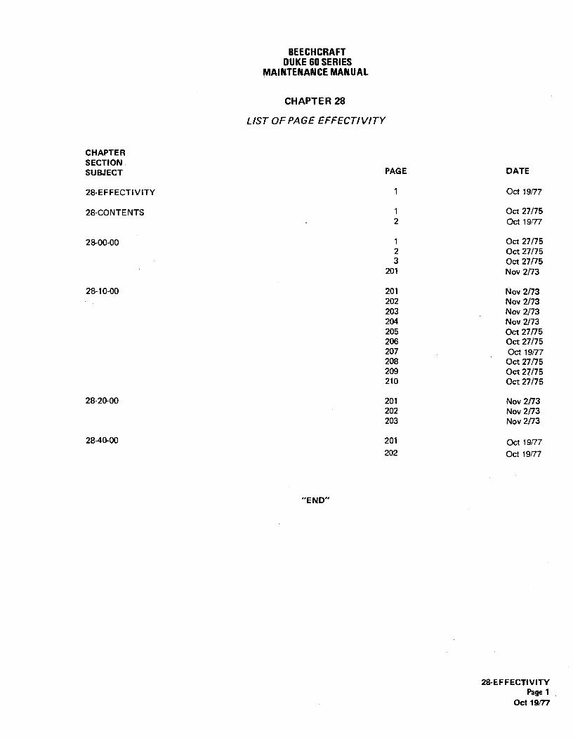
BEECHCRAFTDUKE60 SERIES
MAINTENANCEMANUAL
CHAPTER 28
LIST OF PAGE EFFECTIVITY
CHAPTERSECTION .
SUBJECT PAGE DATE
28-EFFECTIVITY 1 Oct 19/77
28-CONTENTS 1 Oct 27/752 Oct 19/77
28-00-00 1 Oct 27/752 Oct 27/753 Oct 27/75
201 Nov 2/73
28-10-00 201 Nov 2/73202 Nov 2/73203 Nov 2/73204 Nov 2/73205 Oct 27/75206 Oct 27/75207 Oct 19/77208 Oct 27/75209 Oct 27/75210 Oct 27/75
28-20-00 201 Nov 2/73202 Nov 2/73203 Nov 2/73
28-40-00 201 Oct 19/77202 Oct 19/77
"END"
28-EFFECTiVITYPage 1
Oct 19/77

BEECHCRAFTDUKE60 SERIES
MAINTENANCEMANUAL
CHAPTER 28 - FUEL
TABLE OF CONTENTS
CHAPTERSECTION
SUBJECT SUBJECT PAGE
GENERAL 28&OO 1Description and Operation 1
Fuel Cells 1Fuel Crossfeed 1Fuel Boost Pumps 1Fuel Ceff Drains 1
Maintenance Practices 201Fuel Handling Practices 201Airplane Defueling 201
STORAGE 28-10-00 201Maintenance Practices 201
Nacelle Fuel Cell Removal 201Nacelle Fuel Cell Installation 201Inboard Leading Edge Fuel Cell
Removal 201Inboard Leading Edge Fuel Cell
Installation 202Installation of Velcro Tape with
Replacement Fuel Ce!Is 202Inboard Leading Edge Baffled
Fuel Cell-Flapper Valve Inspection 203Box Section Fuel Cell Removal 204Box Section Fuel Cell Installation 204Outboard Leading Edge Fuel Cell
Removal 204Outboard Leading Edge Fuel Cell
installation 205Wet Wing Tip Removal 205Wet Wing Tip Installation 205Leak Test 207Leakage Checks and Repairs
(Wet Wing Tip) 207Fuel Cell Leakage Check 208
Fuel Cell Repair 209Goodyear Fuel Cells 209Unireyal Fuel Cells 210
DISTR IBUT ION 28-20-00 201, Maintenance Practices 201
Fuel Boost Pump Removal 201Fuel Boost Pump Installation 201Engine Driven Fuel Pump Removal 201Engine Driven Fuel Pump Installation 201Engine Driven Fuel Pump Adjustment 201Fuel Selector Valve Removal 201
28-CONTENTSPage 1
Oct 27/75

BEECHCRAFTDUKE60SERIES
MAINTENANCEMANUAL
CHAPTER 28 - FUEL
TABLE OF CONTENTSTCont'd)
CHAPTERSECTION
SUBJECT SUBJECT PAGE
DISTRIBUTION 28-20-00Maintenance Practices
Fuel Selector Valve Installation 201Fuel Selector Valve Control Cable Removal 201Fuel Selector Valve Control Cable Installation 202Fuel Selector Valve Control Cable Rigging 202Vent Float Valve Removal 202Vent Float Valve installation 203Flared Fittings 203External Fuel Cell Vent Line 203
IND1CATING 28-40-00Maintenance Practices 201
Fuel Quantity Indicators 201Fuel Transmitter Removal 201Fuel Transmitter installation 201Adjusting and Testing Fuel
Gaging System 201Fuel Flow indicator 201Fuel Sight Gage 202Fuel Sight Gage Removal 202Fuel Sight Gage Installation 202
"END"
28-CONTENTSPage 2Oct 19/77