of high energy aviation fuels from rdyanced coal … · unit volume than conventional fuels....
TRANSCRIPT
AD-A192 333 PRODUCTION OF HIGH ENERGY AVIATION FUELS FROM RDYANCED 1/1COAL LIQUIDS PHASE 1(U) STRAT CO SALT LAKE CITY UTJ DOWNEN APR 9? AFWRL-TR-87-2036 F33615-86-C-2668
UIlCLASSIFIED F/G 21/2 N
Flu
MICRcUPY RESOLUTO TEST CHART
-q lip, -. AV 1w
*10

AD-A 182 333 lCIfC
AFWAL-TR-87-2036
PkODUCTION OF HIGH ENERGY AVIATION FUELSFROM ADVANCED COAL LIQUIDS
* JOHN DOWNEN
STRAT CO.4597 JUPITER DRIVESALT LAKE CITY, UTAH 84124
APRIL 1987
FINAL REPORT FOR THE PERIOD JUNE 1986 - FEBRUARY 1987
APPROVED FOR PUBLIC RELEASE; DISTRIBUTION UNLIMITED
AERO PROPULSION LABORATORYAIR FORCE WRIGHT AERONAUTICAL LABORATORIESAIR FORCE SYSTEMS COMMANDWRIGHT-PATTERSON AIR FORCE BASE, OHIO 45433-6563
87

Um WV_ 7
NOTICE
When Government drawings, specifications, or other data are used for anypurpose other than in connection with a definitely related Government procure-ment operation, the United States Governent thereby incurs no responsibilitynor any obligation whatsoever; and the fact that the government may haveformulated, furnished, or in any way supplied the said drawings, specifica-tions, or other data, is not to be regarded by implication or otherwise as inany manner licensing the holder or any other person or corporation, or convey-ing any rights or permission to manufacture, use, cr sell any patentedinvention that may in any way be related thereto.
This report has been reviewed by the Office of Public Affairs (ASD/PA)and is releasable to the National Technical Information Service (NTIS). AtNTIS, it will be available to the general public, including foreign nations.
This technical report has been reviewed and is approved for publication.
WILLIAM E. HARRISON III ARTHUR V. CHURCHILL, ChiefFuels Branch Fuels BranchFuels and Lubrication Division Fuels and Lubrication DivisionAero Propulsion Laboratory Aero Propulsion Laboratory
F3R TEE COMMANDER
Fuels and Lubrication DivisionAero Propulsion Laboratory
"If your address has changed, if you wish to be removed from our mailinglist, or if the addressee is not longer employed by your organization, pleasenotify AFWAL/POSF , Wright-Patterson AFB, Ohio 45433-6563 to help usmaintain a current mailing list."
Copies of this report should not be returned unless return is required bysecurity considerations, contractual obligations, or notice on a specificdocument.
I41 i " T l l Y .. |

DISCLAIMER NOTICE
THIS DOCUMENT IS BEST QUALITYPRACTICABLE. THE COPY FURNISHEDTO DTIC CONTAINED A SIGNIFICANTNUMBER OF PAGES WHICH DO NOTREPRODUCE LEGIBLY.

UNCLASSIF lED
STRATRCE.ORT DOUMNATO PAGE OAS OftTOIN ORGNIZTO
UPO MONE (op LSW. TON In b.~ RE4KII A
4597JupFierDrv
4a.- "AM OF PUNOONG SPONIN b. OFFICE SYMBO 70. MA T gF NITOMIN OAU TION NME
or dokew AFo Prpulsin LCbrator
NOA"TO INACCE1SPONONO
II-TTEX Xuc*cait* 65502F 1 3005 I 20 r 63
Production of High Energy Aviation Fuels From Advanced Coal Liquids
12. PESONAL AUTHORS)
John Downen
CUTI CODS is. SUDIECYTERM (Cer4Weuon rown 0 noem adwf y bloc numnber)
from coal liquids. The coal liquids used in this program were pruduced from the CloseCoupled Integrated Two Stage Liquifactior System (ISTL) plant at Wilsonville Alabama. Theliquids were derived from subituminous coal, Wyodack upper seam, from Gillete Wyoming. Thecoal liquids were distilled into a 300-625'F fr~ction. Hydrogenation experiments werecon~ucted on this distillate fraction usin~g the Hydrogenation Reactor System (HRS) locateddt Wright-Pattersun AFB, Ohio. Shell 424 nickel/mlybdenum CatdlySt Was used forheteroatwn removal and aromnatics saturation. The report details the analysis ut these
* hydrogenated candidate fuels.
20 L)iSTRIBUTIOWAVAIILABILITY Of AIISTRA(T 1 AARTRA(T ',ICURTy (C ASII(AION
9)UNCLA$SgIIi0UftLMITfD 0 SAWE AS RPT Lii DilL kjSIR% UNCLASSIFIED22& NAME O RESPONtSIOLf INDIVIDUAL 2 1b tFif P40NF (fIclude Area CMMd,) 0111(i %YM1I4t
DOe.,1473. JUN as ftwous edons ae Ato SECRIY C iFICATON~ 01 T-4; IIA(i
~ UNCLASSIFIED
I'12 -A.f* *~ : x % % .y .< .. . I-

TABLE OF CONTENTS
I NTRPDUCTION AND ACKNOWLEDGMENTS ...................... .1HE §YDROGENATION REACTION SYSTEM ............... .
TEST RESULTS .........................................-- 4SEST DATA .............. ... ..............................
TABLE 1 TEST MATRIX .................... 9.............
TABLE 2 DATA ON COAL LiuI FEEDSToCK ................. 8
t ABLE EFFECT OF ;EACTION TEMPERATURE ON PRODUCTS....8TABLE LFFECT OF PRESSURE ON PRODUCTS ................ 9ABLE 5 EFFECT OF RESIDENCE TIME ON PRODUCTS .......... 9ABLE 6 EFFECT OF CATALYST TYPE ON PRODUCTS-......i...
- TABLE 7 EFFECT OF LATALYST TYPE ON PRODUCTS.......... LTABLE 8 EFFECT OF CATALYST TYPE ON PRODUCTS......... : 18
RESULTS OF FURTHER ANALYTICAL WORK ........ ........ 1-- RYABLE 9 GC/MS RESULTS ON SELECTED PRODUCTS ........... 12
TABLE 10 EFPECT OF REACTION TEMPERATURE ON PRODUCTCOMPOSITION .................................. 12
-- TABLE 11 PROPERTIES OF C10 HYDROCARBONS ............... 13
RECOMMENDATIONS .. 9....................................... IsREFERENCES ........ . ................................ .... 16APPENDIX A GRAPHIC PRESENTATION OF TEST DATA....... !.:A
FIGURE 1 EFFECT OF IEMPERATURE ON SULFUR........ .. AtFIGURE 2 EFFECT OF TEMPERATURE ON NITROGEN ........... A2FIGURE 3 EFFECT OF TEMPERATURE ON HYDROGEN ........... A3FIGURE 4 EFFECT OF /EMPERATURE ON DENSITY............A4FIGURE 5 EFFECT OF PRESSURE ON SULFUR ................ A5FIGURE 6 EFFECT OF PRESSURE ON NITROGEN ............. :AFIGURE 7 EFFECT OF PRESSURE ON HYDROGEN ............. A9FIGURE 8 EFFECT OF PRESSURE ON DENSITY ............... A8FIGURE 9 EFFECT OF PRESSURE ON SULFUR ........ o.....A9FIGURE 10 EFFECT OF PRESSURE ON NITROGEN-...'.......A10FIGURE 11 EFFECT OF PRESSURE ON HYDROGEN ............. AllFIGURE 12 EFFECT OF PRESSURE ON DENSITY ..............AlFIGURE 13 EFFECT OF CATALYST TYPE ON SULFUR.......... AlFIGURE 14 EFFECT OF CATALYST TYPE ON NITROGEN ........ A14FIGURE 15 FFECT OF CATALYST TYPE ON HYDROGEN ........ A15FIGURE 16 EFFECT OF CATALYST TYPE ON DENSITY ......... A16FIGURE 17 EFFECT OF CATALYST TYPE ON SULFUR .......... A17FIGURE 18 EFFECT OF CATALYST TYPE ON NITROGEN........AFIGURE 19 EFFECT OF CATALYST TYPE ON HYDROGEN ........ A1FIGURE 20 EFFECT OF CATALYST TYPE ON DENSITY ......... A20FIGURE J EFFECT OF CATALYST TYPE ON SULFUR .......... A21FIGURE 2 FFECT OF CATALYST TYPE ON NITROGEN ........ A22FIGURE 23 EFFECT OF CATALYST TYPE ON HYDROGEN.........A23FIGURE 24 EFFECT OF CATALYST TYPE ON DENSITY ......... A24FIGURE 25 EFFECT OF TEMPERATURE ON AROMATICS ......... A25FIGURE 26 EFFECT OF TEMPERATURE ON NAPHTHENES ........ A26FIGURE 27 FFECT OF TEMPERATURE ON OLEFINS...........A27FIGURE 28 EFFECT OF TEMPERATURE ON PARAFFINS ......... A28FIGURE 29 TEMPERATURE VS SATURATES & UNSATURATES ..... A 29
ii

ANALYSIS OF COAL LiquID....... .. .. . .... . .. . .. ......... B81RuN CONDITIONS AND SCHEMATIC OF THE TSI FACILITY ...... B5LETTER AND REPORT FROM J 9 A ASSOCIATES, INC .......... B9SCHEMATIC OF THE HRS. .. .. . .. .. . .... . .. . ............... .B19BROCHURE ON THE SHELL 424 CATALYST ................... B20DIAGRAM AND DISCUSSION OF REACTOR..... .. .. ........ ... .B22
Brig A&xDITI ?AD
Ava11ab1l1ty codes
11 11p ,,dllj .

P7DCTION OF HIGH ZRGY AVIATION FUELS
from
WJAMCED COAL LIQUIDS
John Downen, Principal Investigator
Strat Co., 4597 Jupiter Drive, Salt Lake City, Utah
March 15, 1987
Introduction and Acknowledgments
Strat Co. initiated an innovative research effort supported bythe AFWAL/Aero Propulsion Laboratory to examine the feasibilityof producing higher energy aviation fuels from domestic coalresources. This effort would address two issues; first, it wouldassess aspects of a domestic resource, coal liquids, that haveheretofore been considered to be of little value as an aviationfuel feedstocki and, secondly, it would produce liquids suitableas fuels for aircraft of increased speed and range.
The work was conducted at the Fuels Branch of the Aero PropulsionLaboratories at Wright-Patterson Air Force Base. The assistanceof the staff of the Fuels Branch is gratefully acknowledged, forits conduct of the experimental and analytical work of theproject.
Conventional aviation fuels are comprised primarily of normal andiso-paraffins which are the major constituents of most crudeoils. Aromatic molecules naturally exist in some.crude oils andothers are generated in refinery cracking and rot~rmingprocesses. Olefins are almost exclusively a result of thecracking and coking process. Aromatic molecules aresignificantly more dense than paraffinic molecules and thereforecontain substantially more energy per unit volume.Unfortunately, aromatics do not burn well in conventional enginesand as a consequence maximum aromatics specifications andcorresponding minimum smoke point specifications have been
* established for conventional jet fuels.
Naphthenic molecules appear to be the best prospects for improvedhydrocarbon aircraft fuels. They retain most of the advantagesof both paraffins and aromatics. Like paraffins, the naphthenesare saturated and thus are more stable than the unsaturatedaromatics and olefins. Naphthenes also burn more like paraffins,without most of the smoke problems related to aromatics. Becausenaphthenes are cyclic paraffins, their density is greater thanthe normal and iso paraffins that make up most of the volume of
i '~( V f~.~ ~ * d Y.Ed\~ . a

conventional fuels. Naphthenes therefore contain more energy perunit volume than conventional fuels.
Unfortunately, naphthenes do not naturally occur in most crudesin high enough concentrations to significantly affect the energydensity of conventional aviation fuels. The most likelyprocesses for making the volumes of naphthenes needed foradvanced fuels will involve careful hydroprocessing of aromaticmolecules of the appropriate size in order to saturate theirdouble bonds without breaking their rings, thus converting themto naphthenes. Hydrocarbon liquids derived from certain coalscontain high percentages of those aromatic molecules and maybecome one of the prime sources of the feedstocks needed forproduction of advanced fuels.
Coal tars as secondary products from coal gasification projectswere originally considered as possible feedstocks for thisprogram. As a first approximation, the characteristics of thesematerials were found to be not suitable for volume production ofhigh quality fuels. The difficulties related to theirprocessing, transport and storage and the potentialcarcinogenicity of the heavier tars were the principal factors inthis decision. These materials also are now not expected tobecome widely available on the domestic market in the nearfuture. For a number of reasons, therefore, a middle distillateof the coal liquids from the DOE/EPRI Advanced Two-StageLiquifaction Facility (TSL) which is operated by Catalytic Inc.at Wilsonville, Alabama was determined to be a better feedstockfor Phase I of this program.
The feedstock evaluated in this effort was derived from upperseam Wyodak (Wyoming subbituminous) coal which was processed atthe TSL. It was produced in Run #251 during August 1986 underthe sponsorship of the Department of Energy, the Electric PowerResearch Institute (EPRI) and several industrial supporters. Aschematic of the TSL facility is included in Appendix B as is areport on the composition of the liquid before it wasfractionated.
Two drums of the TSL liquids were fractionated by J&A Associates,Inc of Gold8 n, Colorado in a 25 gallon batch still. Only the340 F to 590 F cut (ASTM D86) was shipped to AFWAL forhydrotreatment into candidate fuels (see Table 2). Appendix Balso includes a letter report from J&A outlining the results ofthe distillation of the two drums along with pertinent data.
Sullivan 1,2,3 had previously evaluated coal liquids from the TSLand produced fuels which met current jet fuel specifications. Inthis effort, the objective was not necessarily to producespecification fuels but to produce a variety of liquids whichmight be considered for future advanced applications. Because ofa lack of product fractionation equipment and of fuel "polishing"facilities such as clay treatment and additives, no real attemptwas made to produce finished specification fuels.
2
.- |.-% £ ; m,'l %. .. lfa.%V'[ -- %a y, 9 '
4. . * .'

The effect of reaction conditions on the quality of fuel wasdetermined within the limitations of the analysis equipment atAFWAL. In addition, this effort was Phase I of a morecomprehensive program which would optimize fuel productionconditions and evaluate these materials in simulated advancedpropulsion applications. In the Phase II e3pansion of thiseffort, feedstocks other than coal liquids, including energeticgases, would also be evaluated and compared. Some details of thePhase II effort will be further discussed in the"Recommendations" Section of this report.
The Hydrogenation Reaction System
The reaction system used in this program was located in the Fuelsand Lubrication Building (Building 490) in Area B at Wright-Patterson Air Force Base near Dayton, Ohio. The HydrogenationReaction System (HRS) was an automated pilot plant capable ofstudying the processing associated with feedstocks such aspetroleum, heavy oils, tars, coal liquids, shale oil etc. Itsmain function, however, is to study hydrogenation andhydrocracking processes needed to produce suitable candidates fortransportation fuels such as jet and diesel from a variety ofsources. The unit was built by Xytel Inc. of Chicago from adesign based on Air Force requirements.
Appendix B includes a schematic of the HRS. It is basically atwo-reactor system with the capability of operating the reactorsin series. For instance, in upgrading high fuel-bound nitrogenfeed like western shale oil, the first reactor could be used as a"guard" reactor to remove nitrogen to the parts per millionrange, remove metals such as arsenic and iron and to saturateolefinic hydrocarbons, to keep the main hydrocracking reactorfrom being poisoned. This procedure is analogous to typicalrefinery operations with these materials and is used in theUnocal shale oil upgrading facility near Parachute, Colorado.However, in this study only one reactor was used since "lifestudies" on the catalyst were beyond the scope of the effort.
The HRS facility has the normal capability of supplying liquidand gaseous fluids to the reactors. The temperatures in thereactor are monitored and controlled by a thermocouple located ina thermowell on the centerline of the reactor. The thermocouplecan traverse the length of the reactor. The facility has thecapability of liquid feed rates up to 600 cc/hr with hydrogenflows being limited to approximately 35 standard cubic feet perhour. The reaction temperatures are limited to approximately950°F with a pressure capability of nearly 3000psig. Thereaction products can be scrubbed to remove hydrogen sulfide andammonia and the gaseous products can be separated from theliquids. Gas analysis using an on-stream gas chromatograph canbe made to facilitate accurate material balances. The facilityis physically located in Room 154 of Building 490 in a high-bay
3V !4

area equipped with more than adequate safety precautions. Acomplete description of the HRS is expected to be available inreports originating from the AFWAL Fuels and Lubrication Divisionand will not be presented here.
This facility will be of great value to the USAF as it developsits understanding of the processes for producing high qualityfuels for future hypersonic aircraft. In addition the basicsystem is being modified so it can be configured to evaluatecatalyst systems for endothermic fuels needed for high speedflight in the atmosphere. The operations made possible by thisconfiguration will become the focus of the Phase II part of thisprogram.
Test Results
A segies 8f hydrogenation tests were performed on the coal liquid(340 -590 F) distillate to evaluate the effect of the reactionparameters on the resulting products. Sufficient products wereobtained to provide analytical data to ascertain the quality ofthe products as suitable feedstock for candidate fuels. Completejet fuel specifications on the products were not run since noattempt was made to produce "polished" usable fuels. Such testsas corrosivity and thermal stability could be met through correctfinishing processes such as stripping and clay treatment. Theobject of this study was to produce suitable material for furtherrefining including desired fractionation.
No attempt was made to evaluate catalyst life. Before a valideconomic analysis of the cost of the products could be made, dataon the life of the catalysts would have to be obtained by furtherwork, as it has a major effect on refinery economics and must bemaximized for production operations. Further work would also beneeded in order to develop information for projections for scale-up and continuous production of any of these liquids. This wasoutside the scope of the Phase I study and will be developed fromthe Phase II data.
For this effort two catalysts were selected to representconventional off-the-shelf hydrotreating catalysts. They were anickle-molybdenum (NiMo) and a precious metal catalyst whichusually has increased hydrogenation activity. Shell 424, NiMo onalumina, was tested on the feedstock in 85% of the runs and thisdata was compared to an Engelhard sulfided 0.5 wt% Pt on carboncatalyst which was acquired from the Hercules Research Center atWilmington, DE. A descriptive brochure on the Shell 424 catalystis included in Appendix B.
Reaction conditions studied included temperatures: 6000-7000 F,pressures: 200-2500 psig, and feedrates: 0.19-0.39 ibm/hr(LHSV: 9.5 to 1.0). Table 1 is the test matrix as the projectwas conducted. Further tests were scheduled with the Pt catalystand another series was planned with a nickle-zinc catalyst but
4
..................vv vvvv ~~ 9 vv-.vv ~**v*
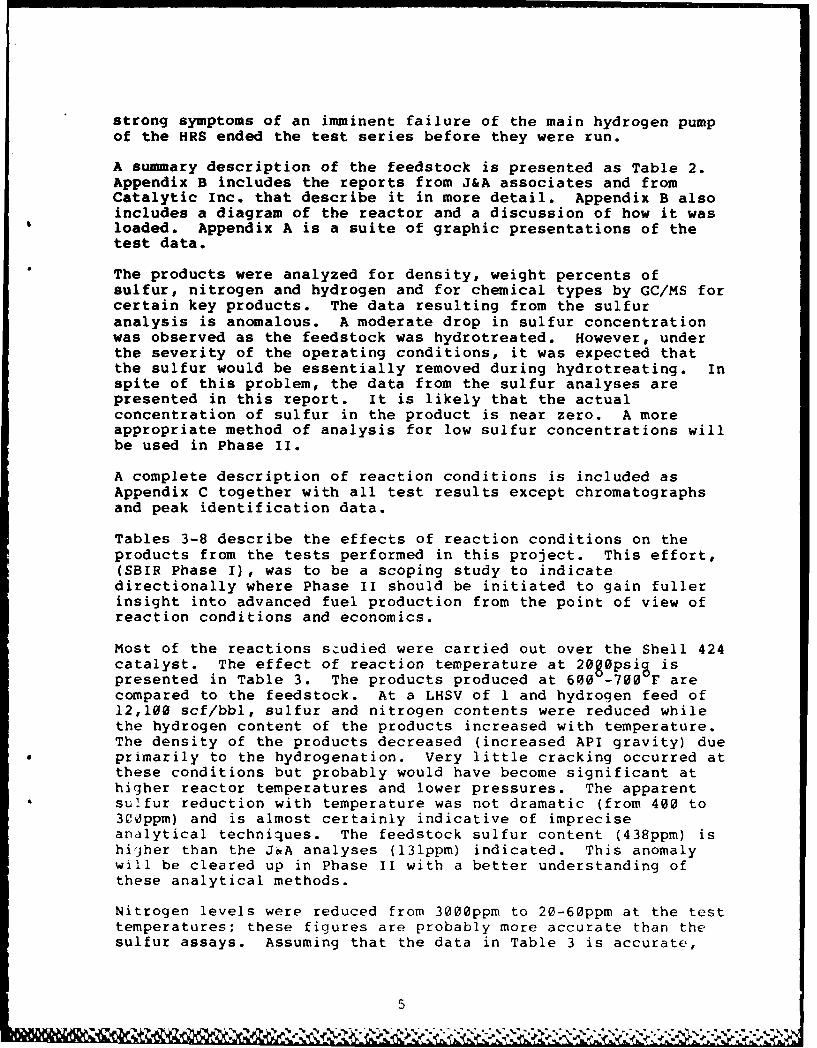
strong symptoms of an imminent failure of the main hydrogen pumpof the HRS ended the test series before they were run.
A summary description of the feedstock is presented as Table 2.Appendix B includes the reports from J&A associates and fromCatalytic Inc. that describe it in more detail. Appendix B alsoincludes a diagram of the reactor and a discussion of how it wasloaded. Appendix A is a suite of graphic presentations of thetest data.
The products were analyzed for density, weight percents ofsulfur, nitrogen and hydrogen and for chemical types by GC/MS forcertain key products. The data resulting from the sulfuranalysis is anomalous. A moderate drop in sulfur concentrationwas observed as the feedstock was hydrotreated. However, underthe severity of the operating conditions, it was expected thatthe sulfur would be essentially removed during hydrotreating. Inspite of this problem, the data from the sulfur analyses arepresented in this report. It is likely that the actualconcentration of sulfur in the product is near zero. A moreappropriate method of analysis for low sulfur concentrations willbe used in Phase II.
A complete description of reaction conditions is included asAppendix C together with all test results except chromatographsand peak identification data.
Tables 3-8 describe the effects of reaction conditions on theproducts from the tests performed in this project. This effort,(SBIR Phase I), was to be a scoping study to indicatedirectionally where Phase II should be initiated to gain fullerinsight into advanced fuel production from the point of view ofreaction conditions and economics.
Most of the reactions s.udied were carried out over the Shell 424catalyst. The effect of reaction temperature at 20g0psig ispresented in Table 3. The products produced at 600 -700 F arecompared to the feedstock. At a LHSV of 1 and hydrogen feed of12,100 scf/bbl, sulfur and nitrogen contents were reduced whilethe hydrogen content of the products increased with temperature.The density of the products decreased (increased API gravity) dueprimarily to the hydrogenation. Very little cracking occurred atthese conditions but probably would have become significant athigher reactor temperatures and lower pressures. The apparentsulfur reduction with temperature was not dramatic (from 400 to300ppm) and is almost certainly indicative of impreciseanalytical techniques. The feedstock sulfur content (438ppm) ishigher than the J&A analyses (131ppm) indicated. This anomalywill be cleared up in Phase II with a better understanding ofthese analytical methods.
Nitrogen levels were reduced from 3000ppm to 20-60ppm at the testtemperatures; these figures are probably more accurate than thesulfur assays. Assuming that the data in Table 3 is accurate,
5

then the Shell 424 catalyst is not effective in producing asulfur-free or nitrogen-free product for advanced fuelapplications where these components would cause high temperatureinstabilities, although further work and better analyses may leadto conditions of better performance by the catalyst. In anyevent, the Shell 424 catalyst could be used in guard reactors toreduce nitrogen levels and perhaps trace metal and olefincontents to levelp where extremely active catalysts would not bepoisoned in downstream hydrogenation/hydrocracking operations.
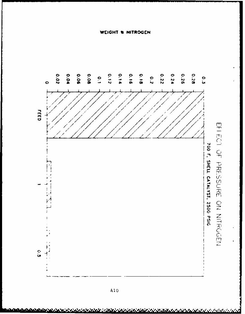
In Table 4 the effect of reaction pressure on hydrogenation wasevaluated in several of the tests. The effect of increasedpressure on the reduction of sulfur and nitrogen and the increasein hydrogen content are not apparent from tests run at 2000psigand 2500psig. Tests at lower and higher pressures were beyondthe scope of this effort and probably would have given moreinsight into the effect of greater pressure range. The tests inTable 4 were all run at 700 F, LHSV=I and using the Shell 424catalyst. From this minimal data there would seem to be no needto hydrotreat at higher pressures.
The effect of residence time was evaluated and presented in Table5. These tests were performed at LHSV of 1 and 0.5, at apressure of 2500psig and temperature of 700 F using the Shell 424catalyst. Here again, sulfur content of the product wasapparently not greatly influenced by the greater residence time(lower flow rate). The nitrogen content was reduced from 74ppmto 50ppm at the lower flow rate and the hydrogen contentincreased by 2% to 12.93%
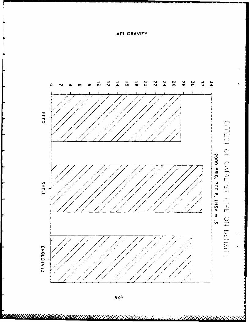
Table 6 evaluates the effect of the Shell 424 catalyst comparedwith the presulfided Engelhard 0.5 wt% Pt on carbon and clearlyindicates, with the minimum data obtained, that the Pt is not aseffective as the NiMo in removing sulfur and nitrogen from thefeed. Also the hydrogen content of the Pt catalyst-producedproduct was lower than that with the Shell 424 material. Thesebracketed tests were run at reaction temperature of 6000 F,pressure of 2000psig and LHSV=l.
The effect of a higher reaction temperature, 7000 F, wasdemonstrated on the two catalyst types in Table 7. The sameresults are found as those observed at the lower reactiontemperatures. At 700°F the Pt catalyst also produced a muchhigher gravity (41.700 API) indicating that some cracking mayhave been occurring. It is highly likely that such tracecompounds as sulfur, nitrogen and metals may have poisoned theusually highly reactive Pt catalyst.
In Phase II the Pt catalyst will be used to evaluate advancedfuel production but an appropriate guard reactor will be used.As Pt catalysts are expected to function well in an endothermicregime, the data from the Pt catalyst in this program may serveas baseline information for the next phase. In Phase I, this
6 I

L approach was not practical based on scheduling and fundinglimitations.
Results on the two catalyst types at lower feedrates arepresented in Table 8 and the results and conclusions are similarto those in Table 7.
Test Data
TABLE 1
TEST MATRIX
test no. 6emp. catalyst press. feedrate LHSV gas rateF type psig lbs mass/hr scfh **
HRS-016 FEEDSTOCKHRS-017 600 NI-MO 2000 0.39 1 15HRS-018 600 NI-MO 2000 0.39 1 15HRS-019 600 NI-MO 2000 0.39 1 15HRS-020 650 NI-MO 2000 0.39 1 15HRS-021 695 NI-MO 2000 0.39 1 15HRS-022 FEEDSTOCKHRS-023 700 NI-MO 2000 0.39 1 15HRS-024 700 NI-MO 2000 0.39 1 15HRS-025 700 NI-MO 2500 0.39 1 15HRS-026 700 NI-MO 2500 0.39 1 15
- HRS-027 700 NI-MO 2500 0.39 1 15HRS-028 700 NI-MO 2500 0.19 0.5 15HRS-029 700 NI-MO 2500 0.39 1 15HRS-030 700 NI-MO 2500 0.19 0.5 15HRS-031 600 NI-MO 2000 0.39 1 15HRS-032 600 NI-MO 2000 0.39 1 15HRS-033 600 NI-MO 2000 0.39 1 15
- HRS-034 600 Pt 2000 0.39 1 15HRS-035 700 Pt 2000 0.39 1 15HRS-036 700 Pt 2000 0.19 0.5 15
** NOTE: This converts to 12,096 (12,100) scf/bbl of feedstock atLHSV of 1, and 24,200 scf/bbl at LHSV of 0.5, on a one passthrough basis (no hydrogen is recycled).
7
lab9 I

LTABLE 2
DATA ON COAL LIQUID FEEDSTOCK(From J & A Associates Report)
Quantity: 61.3 gallons (at 60 degrees F)_ Volume per unit of liquid: 58.4
Elemental Analysis, wt%Carbon 86.83Hydrogen 12.84Nitrogen 0.25Sulfur 0.01
Distillation (ASTM-D86) OF
1BP 34010% recovered 38230% recovered 43750% recovered 48670% recovered 52490% recovered 566end point 590
TABLE 3
EFFECT OF REACTION TEMPERATURE ON PRODUCTS
- Catalyst: Shell 424(Ni/Mo) Feed Rate: 0.39 lbm/hrPressure: 2000 psig H2 Feed: 12,100 scf/bbl
LHSV: 1
Analyses
Reaction zemperature Sulfur Nitrogen Hydrogen GravityF wgt % wgt % wgt % API
feed 0.044 0.300 12.01 27.45600 0.041 0.070 12.44 29.77650 0.033 0.002 12.93 31.61695 0.006 12.76 31.27700 0.034 0.006 12.78 31.27
•8

TABLE 4
EFFECT OF PRESSURE ON PRODUCTS
Catalyst: Shell 424 Feed Rate: 0.39 ibm/hrTemperature: 700 F LHSV: 1
a
Analyses
Reactor Pressure Sulfur Nitrogen Hydrogen Gravitypsig wgt% wgt% wgt% API
feed 0.044 0.300 12.01 27.452000 0.034 0.006 12.78 31.272500 0.036 0.007 12.73 31.24
TABLE 5
EFFECT OF RESIDENCE TIME ON PRODUCTS
Catalyst: Shell 424 Temperature: 7000FPressure: 2500 psig
Analyses
Feed Rate ibm/hr Sulfur Nitrogen Hydrogen Gravity(LHSV) wgt % wgt % wgt % API
feed 0.044 0.300 12.01 27.450.39 (1) 0.032 0.0074 12.70 31.140.19 (0.5) 0.029 0.0050 12.93 32.03
TABLE 6
EFFECT OF CATALYST TYPE ON PRODUCTS
Pressure: 2000 psigTemperature: 6000 F
Feedrate: 0.39 ibm/hrLHSV: 1
Analyses
Catalyst Type Sulfur Nitrogen Hydrogen Gravitywgt % wgt % wgt % API
feed 0.044 0.300 12.01 27.45Shell 424 (Ni/Mo) 0.041 0.070 12.44 29.77Englehard (0.5 Pt) 0.040 0.262 12.29 28.53
911%*1,11 1 1, 16 1i

TABLE 7
EFFECT OF CATALYST TYPE ON PRODUCTS
Pressure: 29 psigTemperature: 700 F
Fedrate: 0.39 Ibm/hrLUSVu 1
Analyses
-------------------------------------------Catalyst Type Sulfur Nitrogen Hydrogen Gravity
wgt% wgt % wgt % API
feed 0.044 0.300 12.01 27.45Shell 424 (Ni/Mo) 0.034 0.006 12.78 31.27Englehard (0.5%Pt) 0.038 0.161 12.57 41.78
TABLE 8
EFFECT OF CATALYST TYPE ON PRODUCTS
Pressure: 2000 psigTemperature: 700° F
Feedrate: 0.19 Ibm/hrLHSV: 0.5
Analyses
Catalyst Type Sulfur Nitrogen Hydrogen Gravitywgt % wgt % wgt % API
feed 0.044 0.300 12.01 27.45Shell 424 (Ni/Mo) 0.029 0.005 12.93 32.03Engelbard (0.5% pt)0.040 0.151 12.49 29.74
Results of Further Analytical Work
For selected hydrotreating tests, gas chromatographic/massspectographic analyses were run. This data is useful inidentifying basic hydrocarbon types. Saturated hydrocarbons areeither straight-chained normal and iso paraffins or mono-and di-cycloparaffins. These types of structures represent the highesthydrogen content possible, with n-paraffins having the highestpossible content for a given carbon number. The most stableunsaturated hydrocarbons are aromatics, here represented byalkylbenzenes, indans and tetralins, and naphthalenes. Thesematerials are deficient of hydrogen atoms but are stable due toresonance within the aromatic ring. The cyclic compounds can behydrogenated to cyclic paraffins, i.e. naphthalenes becomedicycloparaffins with the saturation of all carbon atoms.
10
A AU" '0 V -a-.

In this effort, the GC/MS data were obtained on selected productsand compared to the feedstock. This data is presented in Table9. Seven classes of compounds are quantified. The first threecategories are paraffinic (completely saturated) while the lastfour are unsaturated aromatics and olefins. Olefins areunsaturated hydrocarbons which are not stabilized by resonance,are usually identified as being unstable and are characterized asgum formers, depending on type. Di-olefins are usually the mostunstable.
The coal liquid from Wilsonville was an excellent potentialrefinery feedstock. It was hydrogenated to a fairly high degreein its production as its hydrogen content was 12.01 wt% with only25.3% aromatics and 1.2 wt% olefins. This data is summarized bygeneral group (paraffins, naphthenes, aromatics and olefins).Table 10 shows the effect of reaction conditions on thesehydrocarbon types. Using the Shell 424 catalyst and reactionpressure of 2666 psig and liquid feedrate of 6.39 lb (mass) /hour (LHSV-l) the effect of increasing reaction temperature ispresented. The paraffin content dropped slightly from 16.1% to13-14% as the temperature was increased. The naphthenes, whichare the candidate compounds for use as high density fuels,increased with temperature commensurate with the decrease ofaromatics. Also, as would be expected, the total hydrogencontent of the product increased as the aromatics and olefinsbecame saturated. As its hydrogen content approaches 13%, a fuelbecomes more acceptable for contemporary jet engines. Futureengines will benefit from the increased volumetric energy bybeing designed to operate efficiently on lower hydrogen contentand heavier cyclic fuels.
The high remaining paraffin content is probably representative ofthe long chained waxes which are typical of liquids fromsubbituminous coal, which have higher freeze points and whichwould tend to raise the freeze point of the products. The freezepoints of these products are significantly higher than those ofmost conventional fuels. Not much cracking occurred under thesetest conditions. The freeze points could be decreased bydewaxing or isomerization of the products although a lessexpensive procedure may be just to decrease the end point byfractionation. Another option would be to use a higher rank coalas the liquifier feedstock which would produce a higherpercentage of aromatics and less paraffins. The fractionationfacilities were not operable at the Air Force laboratory forPhase I but should be available in Phase II to facilitateproduction of as broad a range as possible of suitable matetials.Process economics will be compared based on using wider cuts andconverting the waxes to lower melting isomers versusfractionating a more narrow boiling range product.
Cyclohydrocarbons are more dense than the correspondingparaffins, see Table 11 where n-decane is compared todecahydronaphthalene (decalin). Both molecules contain tencarbon atoms. The specific gravity of the straight chained n-
1I

decane is 6.7342 compared to 0.9611 for the cis-decalin. Alsothe dicyclic decalin produces a lower freeze point and an 18%increase in volumetric heating value. The drawback in usingcyclic hydrocarbons is the reduction in hydrogen content whichaffects fuel combustibility in terms of increased flame radiationand soot formation. These shortcomings can be dealt with and toa considerable extent overcome by engine design.
Table 9
GC/MS RESULTS ON SELECTED PRODUCTS
Test Number, HRS-
(See Table 1 For Corresponding HRS Test Operating Conditions)
016 018 026 021 624 028 631 034
Hydrocarbon type, wt%
Paraffins 16.1 13.3 13.4 13.2 14.6 12.1 15.0 13.9Monocycloparaffins 33.4 37.0 38.0 38.0 39.1 39.6 34.9 33.8Dicycloparaffins 24.0 26.6 33.7 32.2 30.6 35.3 25.3 27.5Alkylbenzenes 7.1 6.3 5.5 5.9 5.8 5.2 6.4 6.8Indan & Tetralins 13.9 13.1 7.4 8.6 8.3 6.0 13.4 14.0Naphthalenes 4.3 3.1 1.5 1.6 1.8 1.1 3.4 3.1Olefins 1.2 0.7 0.5 0.5 0.5 0.6 0.6 0.9
Table 10
EFFECT OF REACTION TEMPERATURE ON PRODUCT COMPOSITION
Catalyst: Shell 424Pressure: 2000 psig
Feed Rate: 0.39 lbm/hrH2 Feed: 12,100 scf/bbl
Reaction Temperature, FHydrocarbon type, wt % feedstock 600 650 695 700
Paraffins 16.1 13.3 13.4 13.2 14.0Naphthenes 57.4 63.6 71.7 70.2 69.7Aromatics 25.3 22.5 14.4 16.1 15.9Olefins 1.2 0.7 0.5 0.5 0.5Total saturates 73.5 76.9 85.1 83.4 83.7Total unsaturates 26.5 23.2 14.9 16.6 16.4Hydrogen, wt% 12.01 12.40 12.93 12.76 12.93
12

Table 11
PROPERTIES OF ClI HYDROCARBONS
n-decane decalin
Formula C1 0 H22 C1 0 H18
Molecular Weight 142.29 138.25Specific Gravit: ,.7342 0.9011Boiling Point, F 345.5 384.5Freeze Point, F -21.4 -45.6Characterization Factor, K 12.61 10.50Hydrogen, Wt% 15.59 13.12Net Heat Of CombustionBTU/lb 19,017 18,324BTU/gal 116,410 137,660
Conclusions
Although the US interest in alternative domestic fossil fuelresources is currently in a lull, it is of interest to visualizethe potential for producing from them not only high qualityconventional fuels but the families of advanced fuels needed forthe next generations of aircraft. Future effort in this areamust be timely, aggressive, meaningful and technically sound.
Comparisons of characteristics of products made with current fuelspecifications4 indicates that the Strat Co. effort demonstrated,within the constraints of the SBIR Phase I resources, that coalliquids could be processed into quality fuels. The feedstockwhich was fractionated into a cut suitable for jet fuelproduction was a high grade material; as received, theconcentrations in it of sulfur, nitrogen and oxygen were lowerthan in most petroleum crudes. This material had beenhydrostabilized as part of its production. Liquids from theproper coals processed in this facility undoubtedly represent oneof the best sources currently available for feedstocks forexperimental high density jet fuels. Developing the concept ofendothermic or heat sink fuels and the need for cyclichydrocarbons, like those available from liquified coal, couldprovide an impetus not only for initiating a viable domestic coalliquids industry but for producing quality advanced fuel for 21stcentury fighters, interceptors, cruise missiles and aerospaceplanes and ultimately for production of refinery feedstocks tosupplement conventional crudes.
Using conventional processing technology and limited support,Strat Co. demonstrated that advanced fuels are possible withinthe state-of-the-art. The Shell 424 catalyst is representativeof this technology and produced suitable feedstock for futurefuels. More extensive information is needed, however, to fully
41 1

define future fuel candidates and areas where more sophisticatedprocessing is needed. Pure or nearly pure hydrocarbon compoundsor mixtures of them will probably be needed for certain advancedmissions; these materials must be identified and specified andarrangements made for their production in a timely and economicalmanner.
Future efforts and modifications to the hydrotreating facilityshould enable the AF to study basic heat effects on fuels to gaininsight into the realistic reaction kinetics and potential heatsink capabilities of candidate fuels. This information wouldthen be used to design, build and operate a simulator forcompletely evaluating the fuel/fuel systems interface under morerealistic conditions.
In looking at the applications of this data to further study forthe production of advanced fuels from coal liquids, thehydrocarbon species needed for endothermic fuels, high densityfuels and the other advanced concepts are most likely to benaphthene molecules that are fully saturated and that don't havethe problems associated with fuels containing high percentages ofaromatics. From the data it is clear that we have substantiallyincreased the percentage of naphthenes. Most coal liquids arevery rich in aromatics and most of the aromatics can be convertedto naphthenes by proper hydrotreating. Obviously, most of thedouble bonds are saturated to form naphthenes although some ofthe rings are broken and the aromatics in that case are convertedto alkanes.
Under the operating conditions of this study, the aromaticspercentage of the treated product was higher than forspecification fuels. By further variations of the operatingparameters and catalyst selection this liquid could certainly bemade into specification fuel. In addition, this treatment wouldalso increase the concentration of naphthenes in the liquid.
The relative concentrations of the various hydrocarbon speciesvary greatly among coals of different origin, quality, and rank.For start material, one would select a high volatile, low-ash,low sulfur coal of medium rank. The details of the operatingparameters of the coal-to-liquid conversion unit will alsoaffect the relative concentrations of the hydrocarbon speciesformed. These processes can typically be varied to affect,within limits, the amount of aromatics produced from anyparticular coal; hence the selection process for producing anyparticular advanced fuel should commence with coal selection,followed by coal-to-liquid process selection and optimization ofprocess operating parameters, then proceed through selection of asequence of processes and corresponding operating parameters todistill, hydrotreat, and further fractionate and concentrate thedesired species. Final concentration would probably beaccomplished mainly by liquid-liquid extraction techniques.
14
i b.

Initially it would appear that producing an advanced fuel byselecting an optimum coal that is rich in aromatics , producingliquids from it under the proper conditions, hydrotreating thearomatics to naphthenes and concentrating them may furnishadvanced fuels at lower cost than making them by synthesis frompure compounds. It also is likely that, although a group ofsimilar naphthenic compounds would be produced rather than singlecompounds, the desired fuel characteristics that are beingdetermined from work with single compounds could be obtained fromsuch a group.
After hydrotreating there will still be some aromatics andparaffins remaining in the liquids. There are a number ofcommercial processes available to remove both paraffins andaromatics to arrive at a liquid that is composed entirely ofnaphthenic compounds of similar molecular weight. Following arerepresentative examples:
For extracting the aromatics, one of a number of commercialliquid-liquid extraction processes could be used. Conceptually,this involves a solvent that dissolves the aromatics but not theparaffins or naphthenes. Commercial processes of this type aresulfolane extractors used to remove benzene, toluene, and xylenefrom high-octane reformate, NMP (n-methyl pyrrolidine) used toremove aromatics from lube oils, and S02 extraction used toremove aromatics from jet fuel. These are the obvious processesand there are others that could be adapted to this application.
A number of commercial processes exist for eliminating paraffins.Molecular sieves are available designed so that naphthenes andprobably much of the iso-paraffins will pass through the sieveand the paraffins will not, and therefore can be recovered byback-flushing. In addition, there are two common commercialdewaxing catalysts, one licensed by British Petroleum whichselectively breaks the long chains into light ends underhydrotreating conditions and lowers the pour point (or freezepoint) of the liquid. The other, licensed by Mobil, behaves muchlike a fluid catalytic cracking unit with a hydrogen atmospherewhere the paraffins are generally converted to olefins andaromatics in almost a de-hydrogenation reaction. A thirdcatalytic dewaxing process was developed by Union Oil Co. in thelate 1970s for dewaxing hydrotreated shale oil to reduce its pourpoint so it could be pipelined from Parachute Creek to the Fruitarefinery without the necessity for heating the pipeline. Thiswas not commercially available as of two or three years ago, butarrangements could probably now be made for it.
Recoaeodations
The AF Fuels Branch has prided itself in keeping pace with fueldevelopment activities. This became clear with the leadershiprole it took in developing fuels from domestic (western) oilshale. However, recent cutbacks in energy research by bothindustry and government dictate that the AF play a larger role ifadvanced fuels are ever to be practical. Recent funding cuts andmanpower reductions require assessment of the modus operandi ofthe Laboratory. Research contracts must be well defir!d and hardhitting; opening up new areas of advancement and not merely"reploughing old turf".
Strat Co. plans to assist the AF in this challenging newendeavor. For Phase II, an aggressive, imaginative program willbe proposed to assist in upgrading the in-house capability of theAF Fuels Laboratory. Outside consultants from industry andacademia will be made available to review the background of fuelrequirements and areas of future development. The internalfacilities of the AF will be operated in an efficient manner todevelop prototype fuels in a timely fashion. Current equipmentshould be modified to supply basic heat sink and chemicalreaction parameters for future designs. Chemical analyses mustbe improved in both type and precision. Difficulty in obtainingcorrect data in a timely fashion will not be satisfactory if theAF is to move out in this area.
Strat Co. will present a proposal for a Phase II program whichwill enable the AF to begin to answer the major fuels-relatedquestions posed by Project Forecast II before they disappear bydefault from lack of attention.
References
1. Richard F. Sullivan, "Two-Stage Catalytic Hydrocracking ofITSL Oil for Jet Fuel and Naphtha", Symposium on CatalyticProcesses in Coal Conversion, presented before the Division ofPetroleum Chemistry, Inc., American Chemical Society, ChicagoMeeting, September 8-13, 1985
2. Richard F. Sullivan, "Effects of Feed Boiling Range onHydrotreating of Wyodak and Illinois ITSL Oils", Paper for DOEDirect Liquefaction Contractor's Conference, Pittsburg,Pennsylvania, November 19-21, 1985
3. Richard F. Sullivan and Harry A. Frumkin, "Refining CoalLiquids: Where We Stand" Chevron Research Company, undated
4. Coordinating Research Council, Inc. "Handbook of AviationFuel Properties" 1983, CRC Report No. 530, CRC, Inc. 219Perimeter Center Parkway, Atlanta GA 30346
16

A PP ENMD IX A
GRAPHIC PRESENTATION OF TEST DATA
A-1
..... ......... .. . .. .. '

W~IGIIT % SULFUR
C' C' C' 0 C)0 Ca 0
A C' ~ C' 0 0o - C' C' Cu C'
C' Ul -~ 01 NJ 01 CA 01 -~ 01
/1* / - A!
-, / - / I,r-i
m
- ' I ' *- - ..
C,/ 7 /
- / / " ' " / ~
A* . / "i
C, I' 'IC'- 4 . / .-
7 , , ~-fl
C) 1)r-.
I -4 -~
/ I
* - 'C!)/ - A. /~
. .. .9
01 -~ 7 7 7 - .-* 9 KC' -- . - ~ (9
* - I* A - / -. / ,, - . - - 'I
A. A
K ~ -~----~--~ - - -~-
'- -1 9 211
-. . . A,
I', A,
-I-I.
r- A, j
.'~ 1-a
-C -. ~ -,

WEIGHT %NITROGEN
C) C) C) C) ) 1 a C ) C rco m) cc N) Il -PI -. -o L4 ) N) N
~T-/ / ' /F']
CIO'
~ r .' /
h. _7
L z r
/~ 23
rr

WEIGH-T % HYDROGEN
N W -4 -n -n 1 o oN
7'1
7~~~~~r -, *, T-7 , / I9-
rn
/o -jT*
C,-
c~n A3

AM! GRAVITY
a) C~o o _ ) ..- o sj: c ~ z
S. . -I _
-. . 2 S .F l
7".' ' ..
"A4

WEIGHT % SULfUR
0 0 00 C' 0
0 * 0 0 0£ C C' -0' 0 Li 00
0 01 - 01 Nj 01 (A 01 . 01
K / / //
' / / ,./ ,,9 ,/ / -i/,"
r IkFT
,~~ ~~~~ ,..,........., .. , , ,. ,
I " / i " , " , . .1./ " i / / .,I"
H f / 1 / " / , ' , " ,"..'/" .i *, , / / , . 7-
-".' * / A " "<~ . / 7/".""$. V- 7." " /" / ' " " . ' I '
Ir / .i7 A / ,. /" / P14' i .7 / ' ". " '"" / / /" A
I 7 .- -" .- -" 7 7 ' / ' .- 77,"
-i
.. 7 .. ' . .
, --r
2• -n '
oIT]
/o / , / - .. L,/iv
xx I
/ , , / i / . t / .,, r'-
I , : , , , . ) I > ( ! )
- -- -- -- -
" .' ". I -1' " 7 / 9/"'"
I' C " ",' / -
/" .*"' / / i . /1
w . . .% j 7 % '

WCIGIfT %NITROGEN
o 00 C$ 0 0 0 0 C
0 N O O - ) .41 Mb Co N)j N) -A mb CO L4
I I
H7~L~FTI , A ' '
I' ,/ //// * . A - / /
m d / /V/
rnLI '7'-
/ A / - A0
I.. - - . - " -A 6

WEIGHT HYDPOGEN
N 0 &C -
o rN iL O J C)rO lN i
A 7
I .. . '

AP CRVT
I.-77

W~I(31IT ~t ~UL7UR
r. e.C, - 1~,
- -, .1.r. -. Ul
.1~~-~~ -
I-,
I~1
-4
-4
Zn
.9
-~ . ~ %V% VVVV~..~'Y%~%.~ .. V
WIGHT SNITROGEN
oh oo N 0 0ob 0A 0b 0w
* * * 0o *-* N N 4 N
0 NI4 * ~ ~4 0 0 N ) 4 ' ~ L
I, A I I I I i I I x7 ~ 1~ ~ A
~ / ~/ ,/ 7 / /r/
I~~~~C 7,/ ,//7'
LIAC')
C' A
A10

WEIGHT t HYDROGEN
O N) Ci A CR 0 S tO C' - N 1,4
I,
Vt / /77/ / I1/ / / / ,/- A
/
/ /7 /7 7/'tn-f 7"'. .7 ' -* 7 / ~,/ i I
7's> //7 7" / ,Qj// 7 7// / t / '~1,K7 / .7, 4 I C)
1-4 -~
'Sn-r
/ LA-uS/ 7 -t
/ rn7' .7 / / / ".7 2 i~
-fr / _
7 / ./ 7/ ,z/~ S17 ~// /
// ,//// A -/4>7> ~fl _
~0IC'
~1
' /
1/ / / / 7 ' ' / / . I.
r / , / / /
/I,
P 4/ ./ / / /11i/i__/ /7 ;,~*j/;ji~ ~tLa 7 / ~, A.
'7,.
1/ I
V /I
/ A,V
.1' 'I
All

API GRAYrTY
. ,, ,'7 . /7/ /7,/,' /, '.. // /7, / /'7 // / "/"/!7.,/ /' , / , ,/ ,,//
o 1, / /- / / / / / / /" / II " / " /4 7, " / . / /" 7" /" A",
,7 / / /. /, / " /2" / 7 A
r
A-,< /, /1//,/
I " / . / / . /, / '/ . / r-, I) . ' , j' ," / / , , / I " / I 4 t.
/7 17, , , //77 , /// /7 ,7
S /' / // / , 7 ' ," / / / A, .I -
/"- / 2~ ."7 /,/ /", / /A.,- "- 7 /-_ , / / /7 /7 ./ /" . .I -
, / / ,/ / / - 7
.7- / 1, / /7 . 7' /
7, / ,//<7 / A -*_ , / / 7/ ',./-/ /
P '0-
AI r'
k .' . ..1 ' 1 .' 2 i ¢. . ; ;: .v ;. : ; ; . . ; :. .'.,',,...:,',.,.,.

WEIGHT *SULFUR
o o 0 0A
* 00
-A LA
A, // -. f7
// /iA/ / / /
/ ,7 /A/37~ %A

WEIGHT % NITROGEN
0P NCoW -A N al C N N P 0) 0
.',m
C)
-r
>
0
V m
SC.
N
ran
A14A
0---
r /-Ar- -K
tor: / /o
.z
A21)
0|"i € ' g' x,.,o ' k, '2 o: 9 . ' ' ""-',,,,,z.. '- ,(,v9..'/. ".'- .,;, .2-) -".:.
[ " li.If lVi f~ii lll ogl g N INIMH 4..,,. .. . / 9.. .-. .C t . .. *J * #. . •

WEIGHT %HYDROGEN
/ / m
C)
-
rrr1
m
U 11>

API GRAVITY
-' -'N N N N N L4o K~ 4L c O 0 N) .m CD CD 0 NJ .4 CP O C'
M
/~~~~ / >i7 17
-77)
A16

WEIGHT 91 SULFUR
C) 0 ' 0 J LA C'C4
/ FT"/
- /7/r
V.' .. ' A17

WEIGHT % NITROGEN
o 0o 0 0 0 IO 0 0 0
0b p) :_ :_ Po -j N) ;' C C ) N)) CD Cd
OD/ ol OD 1/I, (n CD L4 I
7/ //" "///
/ /1'/ ; / // / ""
/ 7 /F-ri.// 7,, / C;In
0-q
m~C)
A18AIo .
K--
U , I-(- " i 0
.I , / , " /
>1/ /i/
I, / / ,' t0 , , / / / / / , ,/
k /7 " " J" / 7 ./ 7"1
A18
*~U,~*~( U~'.f. ~ '~ '~

WEIGHT , HYDROGEN
/7 ,.~/1 /// /7 //"/
/,//// '7,/ ,,7, / / ,. /
' // . / / / "" /7 /" / - 1 q/ / 7' / // /., //
.t,/ "//,/ / _/ _ 7)' / ' -K" '" /' _iC:,.-n-
i / / ,.1t // '.'I--/ / ,/ i
.i,'/ / / !. t /H, . 7' 7 / ' If'
-//7/ // /,. 7-/ // // /I 4 -
rt / . / / "" / " / /' -C
K7 " ! / 7 7 t /7,/ .. " 7.
n " / / /"/- 1 / / i/ /'" t"/ /t ." 1 .' (
/ / / '" I'l / " I..'- ll / / ,//"' / . I G-/" /7 / / //, // ./// 7/ ' ,"IA
Z / / / t ! 7' 7 " / (7 il I./ ,i i / ii/ -
I" 1"/~ ;/ 7 I>[ t, IX > . .7 ,7 ,'"77t' ' ./
/I/ I / 1 ,,1 i ./' li"/ 7 '/ 7. 1 / - / " ' I z-
/ ," ,/ -- , ., / / , / / .' / " 7 ',.
.,P, ," / 1 . ..PI ,/ . , eq P ,/ /" ' V . ' b 1 p -~

API GRAVITY
o ul 0 0n 0 LA 0 LA 0 0
9,, ,,/// /I,'- , ,/" 7',/
-/ "/-m
7 9
-A
A20
1/ 1 7 1- / ' . / / / / II/ /,/ / 0
/ / " "" / Li- U,=/// //< m
< / 77,/ "/,, ., / / 1 / . /,.,/" ,/ .,-
ii I /9 /--7'j, / // ,",/ / - ,." " /"I / I
P1 t / ,' / / / / / / / ./A/
- I t/ / / / / 7,/ / ' 7,9 ,' / / , .
n 1/ / 7 /" "/. / / ,// 77 /, 7 / / , 9/,/" / ,/7 /// /
i, /V / / I / ,/ '9 / " ,.v A7 .. ,9 ,/ - / / /,/
7/ .7 / .. " ," / " 9 7 / 7 / 7 ,./I / / / / 1 9" z /' 9I • ' / - /7 1
A20

WEIGHT • SULFUR
o~c 0'0Co* 0 0 L4
Ci C , ' U 0 ,
I, I/ -', I ' " I '," , " ,, ,
7 /" / 7,//7 f /, ' ,. ,,./ ,, 77 I/ t " / / / ! / / / ,/ i
i " " / t i / ,./I ft i // / . / 7j1
o " -/ ' / _ /. .' " / . ' ,i 7/ .1" i- / I I - I . f . - .," /7 I i
! -",r / " ,/ t/ " ,, ,' /7. ,, i .V..l /7 i i 1 ' , 7 / .," " .t' .i." 1"'7 //" / 7/ ",// / /"A
!/ _ / L. . /t LA t"/ /., L "
-4-
'
/ -1 " YC-)
7-/ / ,"7 /1i , rn"- , I," I ,I/ / I¢ •I _
I. (.
* 7' / ,7/ .,/7 i7 ;/ ,,;7; /n / ix / > 7/ 7'/1/'/" , 7,/7 I' / ,I,-
I, / / /7 / / y.71 yC'/
}i,: 1/,//' /- / I/ / /
aJ / 1 /~ / / 7 ,' ,'/,// ,,,/ ,/ / // i
& I ,' ./ ,/, W ,/,/ ./ .",,.-,./

WEIGHIT %I NITROGEN
o c 0 00o 0 0 0 0b 0
oP 0o 0- ? co 'J
0 ) 4 C ) 4 0 W N ) 40i i
I I I
1/ / /
v /A7I. / / /
/~7 // / /1
7' / / A/2

E~ - ____
WEIGHT ~ HYDROGEN
o .a N) LiE 4 US C~ -J 03 ID 0 -~ NJ LiE
V / / /7 /7' 77 / ,1,I I I, // I I I I I 7j I
I ~ / 7/ 7,' 4 I
I / / / 7/7/ 7/7 77/ ty 7/ -
/ / ,,/ 7 77 7)// / / 7 7 - -7 ,/7 / ,/I
o /7 // "7 77 7/ , - I mI' / / / ,/y /7 7/ /7 /7 1
I' / / / 7," ~ 77 // I
1/ / /7 7/ 7/ '7 ~,/.' Jy 7/ / ' -~ /7 I
/7 /7 ,/ 7' ,,z$/' 7/ /~/CI
NJI ~'
0'0 ~I>-, * / 1~ ~ / / ' /
-JI' /7 / ,/ / / / 'I; -UI / /7 / /'7 7/2 / / A "~7 / ,/,/ ,/// 7/7 / / /7 / / ~ -.
/ /7 / - 7 ' // aI / / / '
- I / / ( /' / , ,7 ,/ /7 '"~ -
/7 // ' / / / */ // ,/ ,7 // 77~7 / Cr I / 7," // ~ / 7/ 7/ , IIi/7
.7 'r y ,I' ~ /7 *// 7/ , /
* ' '~'/ ' / 7"' 7' 7 / - 2F / , ,/ 77 /~ 7' ' "' / / / ~ Lh7, // /7 7 / / / 7/ /
iii C)I. a'Li'
-- / / / ~/ ,, . - 7 / 7 -. I* r ' ' / , / 7 7 ' I / 7 - / 2 4 I -A,7,7 ' / /
/ / / - 7 ,'
/ / / / 7<' '"' /4f/f /7/7/ / / / / 777 7/> ~ 1> *~7/ / , // / /
j~ /,7 / / / / / 7 .7 7/ 7/ ,./ // A= 7-"ai 7 - ' / / / ' / 7 ' / .7 ~
/ 7/ / / ', </7,/7 /7/ " 7 / -'.7 ,// WY~' '/ /7 / /
x> 77 / / 77' ./y 7)
A? 3
~ C Ct .7 "w'.. '~. '. Ct*# ' .~ t....c...-... *c.:.--t.J& -. tsP. 2 7
1 ~~'--'--
APi GRAVITY
oi ,- i, 9/i/ i . I I / A ,.." / ', 71' ,
3 / 7 .1 /"/ ,// / /// / i / / ,
/ // ' - /, / / ¢ I /7,I / /" /" 7", / / / '
l/ /7 / // 7'/ 7"/ /7/ ,,1 / / i / / / " 7/ // A i--V ," , / . / / ,/ /" I -/// '1 /'/ // t,/',/ " "A I
//? 7 "' //./ 7 //r." / / i -i/ ,,,- ,,/ // ,/7 / ,/ .I/ I .
-,// ///-r
,/U3,- II K-'/7 ,./ / , , / / , 'A - "
r- L/ /. t / -j./ 7 " i / " .' t "m / / ,r//t / ' "" 1 ilt ,t.
,/, " " / " // , / / ,/ / /
/7. " ' . .1 " / " "/ "7 / /" "" /
A24
~~W1 ~ *J V *\~ . %b~%.%j"'A

WrIcilT AROMATIC5
o NI ., W 0 N,,, i, Um C' NI, . i
I I . .. I .. . 1 i I IS- 7,/ /.i //" /7, / ,-7 ,7 , / / / ,r"" / /" /7' / • " " / IX
/7,7, /,/ /. ,, / ., / '"7 / ,;I/ ' " ' , l . . / . /_ / , " . • 7
"""/~' 1-- " 7 " ." / / 77 / 7'j?-
o . " / 7 ' ,- /. . " / ' /' /- / ," .-' 1
I> ', .. ~ ' / .7 / ..," ," / / 7 .1" / tr// 77 " "7 H-7, '7/ ,/7iI i
7' "/ i/ -/ " -, / /' '. ,,' /I . " / " / r- -
/ / / 7 ' , ,
- J - /" 7 .7/ --
#"/ , ' '"i'/ ~ i -).4
-f, .' 7, / 7 7"- - '
. ., -
.__ __/_,__ _ _ ._ _"_/_._ ,- __,'
7 . I. - -,," t I.' , ' ," 71 ' V
/ / ' ,' .' , . / / ,4D .
7 " / / ' .' , " I ' C
, / .. . ." . . , . .t!
S t 1 / , .,'" // / , / ,/ , ,7 ,,,.' A
". ,i" / " I . t' / .
A25

WEIGHT 9NAPHTHENES
-L4' 41 OD
7/T
/ A , 'V ' ,
7 , - 7 / 2 / ,'
'7LM' 7/ '//
9~ -4, 77' /'I - 7 I
o~~~~~- C / // -/. '
* LM/ ~
£ c. l ,V
A26n

WEIGHT It OLcrNS
oCo 0 Cb 0 0 Cs - -
F7
A2.7

WEIGHT % PARArrINS
o -' N) CA ~ LI' 01 %J CX) tO o .a N) (A & LI' C' %J
t i ~ ; i ; I I
7.. , /
'7 // ' . , 7 / / i I
i /7 7/ /7 ', / ' / / .7- / , 2 /n ~ ~ / 7/ , - - / / / 7,' 7 I
O / .. ~ ~ // ,' IA - /I. ' ' / , / 7 / // , / / // ,/7 ,> . / A . / ,2 I I
-- . 2 .9 A *' 7? I I
-r________________________ rn
t / / 7/ i/ 7/ A I Ik .7/ /7 /7 7/ *x~ / 7/ :r -J// / / / .f p1
- /1 ~' / .7 ,/ I Lfl -
o V / ,. 7/ 7 IC K17 / / -/ 2 Ir / / / // .. ~ ~~ 7 /j
.77 ,7 // >./ y~ /77/ ,~..7p K..I ,. ,1 ,. -
0
________________ ILO
If -" -,/ 7 ,
V // - ~ /7 /7 '1I 7/ 7+ / ,7 I' In ni
IT- -/ - , -' / 7 7 / ***** 'A.// 77 'V
LI'- ft. / 7 ,7/ -~
o ,' / ./* -,/ A ,//~ ,/ /Is / ~ 7/V ~ ~'<' / /*/y' ,/~ -4 _
77 77' /7 77 // 'I I> -
7,7 -, / / / 7 / 77/ 7/f ~ -~-c'U)
-II -
_________________________________________________ _______________________________________________ \ I
N -
7,' 7 / 7 / a IC,S '-"'' Y/77/7~ -K> <~ 7' 7 I'
/ //7 7" / / ii I -p y..
Li~ t/ 4/ .~ ~" 7,7 7. A I U), / 7~ / / I
/ ~ 7 /t ~ / 7 1' / / S A C)7 7 I fl
I, 7 ~/ 2'~ 7 7 .9' -, ' /~ I7' / 7 I 1
-4 y/t 7'>' <~ /7,' / f / / 7 .9
CA- A '7 '7 , , - 'I0 / " / -- ' - ' 7 ~ 9 "7 /.7 " / /7,7 -,/ A >' 7 -' ''' ~ V / / -~V ,/~/ ~'/>/ .7 7' .9.' .7' .7 /7' /
A28
- % s ~ s

WEIGHT
-,40
U 0 0 0 C 0 Co 0 C Cl C.
-4> ./ -l t' " / , , , /7 .".,, ,IIi / - /", / / " ""'" ""7
" • "
i"
/ " ,, " //""I , ," A , ,'
)tn
A2 "A" 9I [' I
I . . " N " " 4 J
-'J t / .' .. ,. '.
"" ' .' ,/ 7 , / , ) W,
C' "
i 1 , / I . ... " ,' ,,- , / /" / /7 .." /" . I,
C, ., A ,7 /7 7'- -
0" ' f .
1--" C i, ", , \ ,, I IlI/ ,-A * ,.,
L-, A~ . - " ," ," , . ' A_ "
-, . A ,\ . . ..
l ' ' \ " " A'
A29

A PP EN D IX B

CATALYTIC. INC., P. 0. Box 239. Wilsonville. AL (205) 669-6747 i
3 October 1986
Carl SmitsJ & A Associates18200 West Highway 72Golden, CO 80401
Dear Mr.Smits:
Attached is analysis of subbituminous solvent shipped to you on23 September 1986.
W. R. Hollenack
Assistant Plant Manager
WRH :mp
cc: J. R. GoughT. W. JohnsonH. D. SchindlerJ. Downer
Note: Subbituminous coal feedstock was from Wyodak UpperSeam, produced from Kerr-McGee mine near Gillete, WY.
The liquid was produced on Run #251 of the AdvancedCoal Liquefaction Facility.
Bl1-a
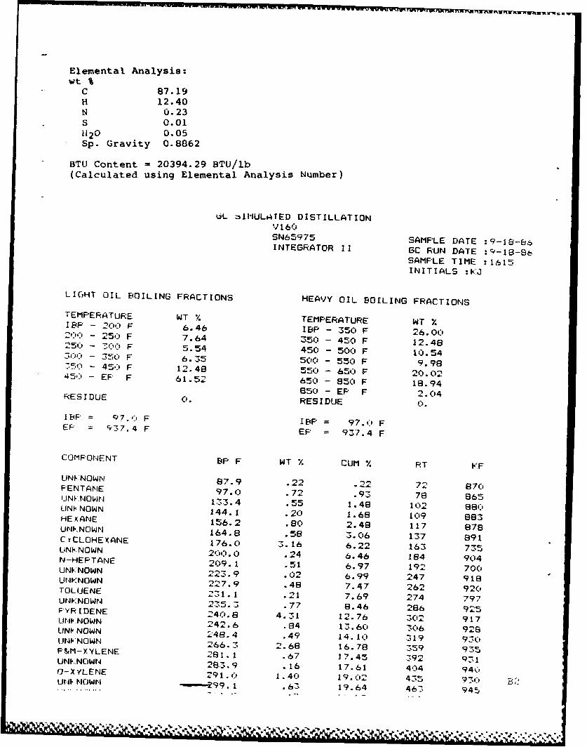
Elemental Analysis:wt %
C 87.19H 12.40N 0.23S 0.01H20 0.05Sp. Gravity 0.8862
BTU Content = 20394.29 BTU/lb(Calculated using Elemental Analysis Number)
OL. 1MULATED DISTILLATIONV 160SN65975 SAMPLE DATE :9-18-66INTEGRATOR IT GC RUN DATE :9-18-6
SAMPLE TIME :1615INITIALS :KJ
LIGHT OIL BOILING FRACTIONS HEAVY OIL BOILING FRACTIONS
TEMPERATURE WT % TEMPERATURE WT %IE'P - 20) F 6.46 IBP - 350 F 26.0020'' - 250 F 7.64 350 - 450 F 12.48250 - 7-W') F 5.54 450 - 500 F 10.54- 350 F 6.35 500 - 550 F 9.98750 - 45) F 12.48 550 - 650 F 20.02450 - EF F 61.52 650 - 850 F 18.94
850 - EP F 2.04RESIDUE 0. RESIDUE 0.
I(F = Q7. 1)F IBP = 97.f FEP = 937.4 F EP = 937.4 F
COMPONENT 8P F WT % CUM % RT KF
UN NOWN 87.9 .22 .22 72 870FENTANE 97.0 .72 .93 78 865UNNOWNr 13_.4 .55 1.48 102 860LJNI NOWN 144.1 .20 1.68 109 683HEY.ANE 156.2 .80 2.48 117 878UNKNOWN 164.8 .58 3.06 137 891CYCLOHEXANE 176.0 3.16 6.22 163 735LINP NOWN 200.0 .24 6.46 184 904N-HEPTANE 209.1 .51 6.97 192 700UNKNOWN 223.9 .02 6.99 247 918UNKNOWN 227.9 .48 7.47 262 920TOL(JENE 231.1 .21 7.69 274 797UNK NOWN 235.3 .77 8.48 286 925FYRIDENE 240.8 4.31 12.76 302 917LINKNOWN 242. 6 .84 13.60 306 926LINiNOWN a48.4 .49 14. 10 319 930UN NOWN 266. 3 2.68 16.78 359 935P&M-XYLENE 281.1 .6b7 17.45 392 931U2NOWN 283.9 .16 17.61 404 940O-X'YLENE 291 . o1. 40 19. - 435 930UNI'NOWN "-,---99.1 .63 19.64 463 945

-..... ... ... "
.NKNOWN 304.8 .09 19.90 483 947UNKNCMN 308.6 1.68 21.58 496 948UNKNOWN 319.5 1.03 22.61 534 951UNKNOWN 333.6 2.78 25.39 583 954UNKNOWN 341.9 .61 26.00 612 957INDAN 350.0 1.10 27.10 640 997
UNKNOWN 354.4 1.11 28.21 658 960'
PHENOL 359.6 .11 28.32 679 1059
UNKNOWN 360.3 1.13 29.45 681 962
UNV NOWN 365.2 .47 29.92 695 963
UNI NOWN 376.5 1.67 31.59 727 968
UNVNOWN 388.5 .32 31.90 761 969UN NOWN 388.6 .29 32.19 762 969LINV NOWN 3Q6.2 1.16 33.35 783 971TETRFALIN 405.0 1.68 35.03 808 1()22
NAPHTHALENE 424.0 .44 35.47 840 1001UNKNOWN 428.9 1.21 36.68 859 980LJNINOWN 434.6 1.12 37.79 881 983UNI.'NOWN 444.7 .68 38.48 920 989UNKNOWN 450.9 1.79 40.27 944 993OUINOLINE 460.0 .31 40.58 979 11162-METHYLNAPHTHALENE 465.8 1.74 42.32 984 971)UNKNOWN 473.8 2.01 44.33 1014 1006UNKNOWN 481.6 .80 45.13 1043 1013UNKNOWN 485.0 .68 45.81 1 )56 1015BIPHENYL 492.0 1.51 47.32 1082 979DIPHENYL-ETHER 496.3 1.70 49.02 1104 97'3UNKNOWN 501.9 .63 49.65 1120 11:31UNP NOWN 511.3 1.63 51.28 1147 1039UNKNOWN 517.2 2.56 53.84 1164 1044ACENAPHTHENE 531.1 .75 54.59 1204 1114UNNOWN 536.0 1.90 56.49 1217 1060UNINOWN 541.0 .78 57.27 1230 1064DIBENZOFURAN 548.6 1.72 58.99 125(0 1123UNKNOWN 560.7 1.83 60.83 1260 1081FLOURENE 568.4 1.53 62.35 1299 1137UNKNOWN 577.3 3.52 65.87 1325 1098ULI0 NOWN 586.3 .88 66.76 1351 11 06SUNPNOWN 593.8 .52 67.27 1373 1117UNKNOWN .,i98.0 2.06 69.33 1385 11.2UNKNOWN 611.0 1.72 71.05 1423 1139UNKNOWN 615.2 1.58 72.63 1435 1144Ut . N OWN 620.3 1.54 74.17 1450 1151UNKNOWN 633.4 2.52 76.69 1488 1169FHENANTHRENE 643.0 1.67 78.36 1516 1187
cJr* NOWN 647.0 .65 79.02 1529 1189UNI NOWN 650.1 1.70 80.72 1539 1194UrNNOWN 661.5 1.00 81.72 1576 1212LWNNOWN 665.8 .610 82.31 1590 12201
UNI NOWN 670. 8 1.6(0 83.91 1606 1228I-METHYLPHENANTHRENE 676.0 1.25 85.16 1623 1358UNKNOWN 680.7 .75 85.91 1640 12469-METHYLANTHRACENE 685.4 .46 66.38 1657 1236UNN NOWN 689.8 .63 87.01 1669 1262UNKNOWN 697.9 2. 18 89.18 1691 1274UNINOWN 711.6 1.17 90.35 1728 1295FLOUIRANTHENE 721.9 .79 91.15 1756 1295UNKNOWN 727.0 1.09 92.24 1771 1320UNKNOWN 732.5 .49 92.73 1787 1329FYRENE 740. 0 .91 93.64 1809 1365UNKNOWN 755.6 1. 13 94.77 1850 1366UNKNOWN 761.3 .30 95.07 1865 1374UNKNOWN 767.0 .19 95.27 1880 1383UNt NOWN 776.5 .43 95.69 1905 1398 B3urItN, OWN 783.7 .84 96.54 1924 140'9
' ,", ,.,7 Ii I, ,",,A . I"ll - - '. ',., ". " ", , 4- _ '-' ._- - - , .T - -:"4' , " "' " "' " ""- -- ".

am 0O .71 if. V.3la
LNKNOWN 649.9 .03 97.96 2116 1517LAR<OWN 857.4 .33 98.29 2147 1532UNKNOWN 857.6 .28 98.57 2148 1533UNKNOWN 870.2 .07 98.64 2200 1558UNKNOWN 879.7 .43 99.07 2239 1576
UNKNOWN 906.1 .37 99.44 2348 1618PERYLENE 937.4 .24 99.68 2477 1651
UNKNOWN 975.0 .17 99.85 2632 1678
UNKNOWN 1020.3 .09 99.94 2819 1759UNKNOWN 1074.9 .06 100.00 3044 1855
B4
. .. . " ." , ." . , ° b ",• % '"% . "%" % ," .% ... '•. ''-'..j. , .%

- CATALYTIC. INC.. P.O0. Box 239, Wilsonville. AL 35186 (205) 669-6747
15 December 1986
Mr. John Downer4597 Jupiter DriveSalt Lake City, Utah 84124
Dear Mr. Downer:
Enclosed are the run conditions and schematic sample location forthe sample of solvent sent to you on 23 September 1986. Thesolvent you received was generated during Run 251-IID period.The solvent was from the low pressure flash (10-15 psig) of the2nd stage reactor effluent.
If I can be of further assistance please advise.
Sincerely,
William R. HollenackAssistant Plant Manager
WRH :mp
cc: J. R. Gough w/out encl.H. L. Crean w/out encl.G. A. Styles w/out encl.T. W. Johnson w/out encl.
B5

Overall ?SL Tiolds
Ihaes 3 Oat&)
Operatinq Ptriod 251-118 251-XC 2S1-XD
Date. 1906 8/2-6/S /7-S/11 8/14-8/18
Days selected 8/2.6/3 0/7.6/8 0/14I/15s
9/4.8/S 6/101/11 8117.8/18
Coal feed rate. I lb/hr 353 354 249
Coal conc. in slrry. Vt M r 33.0 33.1 33.3
Process solvent# wt
Marnd (a) 25(33) 26(34) 26'14)
CI 24 24 24
lot stage
Reaction tmp., oF (average) 919 BIl G0'
Inlet N2 part. press., psi& 2,SI0 2,530 2,530
Coal apace rate.
N? lb/hr/ft3 (700e) 23.7 23.9 16.8
F*203 addition. wt c Mt coal 0.6 1.5 1.5
2nd *tage"eaction temp. or * (average) 743 745 745
Inlet N, part. press.. psia 2.550 2.560 2.580
Space velocity, hr"1
2.79 2.79 1.99
Catalyst type Amocat IC Asocat IC Aeocat IC
Catalyst age. lb (resid*CII/Lb cat 915-1028 1105-1254 1339-1443
CSD
DAS type 2204 2204 -2.2..4 2254
M.1 consumption, wt K AF 6.3*0.1 6.0*0.1 6.3*0,
bnerqy reection, 0 12.7t0.7 13.711.2 12.6t0.6
Yield, wt %--KA coal
Water 13.6*1.1 13.0t0.7 14.1z0,5
N 2 S, CO, CO 2 , N3 10.1t0.4 10.4t0.6 8.2*0.S
Ci-C 3 gas 0.1*0.3 7.0*0.4 6.0*0.8
C4 - distillate 61.0*1.3 58.41.6 60.7t1.8
C 4 . naphtha 19.?ti.1 19.3t1.4 10.9t1.1
Middle distillate 0.3t0.6 11.4t0.7 11.010.4
Distillate solvent 31.1t*.9 27.60.9 30.813.0
IAR d (Wi 3.9 2.2 7.3*1. 7.f 1. 7
AsI concentrate 9.4*0.0 9.3t1.0 .?tO. 3
M2 efficlency
lb C 4 ' dALt/lb 12 Cols 9.7*0 9.7*0.3 9. 7t0.3
,-C 1 selectivity (100)
to C4 . distillate 13.0t1.0 120*1.0 10.012.0
Coal conversion. wt % (N" )
1it stage 94.2*0.0 94.7ti. 94.#xI.0
let and 2nd stage 9S.4t0. 95.7*0.4 96.OtO.3
TWo stage 9S.4I.3 95.3tO.4 94.7g0.7
(lemid # UC) converson,wt 0 feed Id)
lot sta" (e) 34.tl. 1(1.0l.0) 3S.6*1.7(62.3t3.I) 37.0*I.4164. Itl.8,
2nd stage 23.4l.(27.21.4) 17.0t2. 1(20.I*2.7) I. 451.7(20.2z2..i
(a) Data in parenthessa on CI-f-a basis.
(b) Lcl~edO TSL *yet= UC acc lstLo 0
IC) Cresol soluble.
(d) Data in parenthese e are based on W" coal.
(e) OW? coal as 100 Vt UC.

-I0
Ip(AL

SLIDE 27
ccTS "K ash recycle
dM- md
piwrs o
Fj nq twdmpn
vem "owiey 1"buted dkofuia
" h bdtatd iusl + ash
ash concanate
B

J&A ASSOCIATES, INC.1S200 WW HWY 2 GOMen. Coorado 60401 (303) 425-6021
October 27, 1986
Mr. John DOwnen Subject: Preparation of Coal LiquidAPWAL/POSF Hydrotreater FeedWright Patterson Air Force Base Reference:J&A Data Report UOHIO 45433-6563 86-10-582-3510
Dear John,
As you requested in your P. 0. # WL1, we have distilled two drums ofSubbituminous Coal Liquid to your specifications in order to prepare afeedstock for hydrotreating tests. The drums were received fromCatalytic, Inc. Wilsonville, Alabama on August 29, 198 and the desireddistillate was shipped to Wright-Patterson AFB on 4eMi 15, 1986. Thefeedstock produced consisted of 61.3 gallons of 26.60API oil.
The distillation equipment used was our 25 gallon Batch Still (Figure3) which was run at atmospheric pressure until the kettle reached 550 Fand then under vacuum to take the 625°F cut (approximately 500 F maxkettle temperature). This still takes cuts similar to those obtained froma True Boiling Point (TBP) distillation, ASTM D 2892. Each run of 25gallons took two (2) days, even using a reflux ratio of 1:1 in order tospeed up the work. During the distillations, data were recorded each timea receiver was drained (3.5 liter). Products were nitrogen blanketed asthey were collected in order to preclude oxidation and polymerization.
Results are given in the enclosed tables and figures.
Table , gives the overall results and the analyses requested on the300-625 F fraction (hydrotreater feedstock).
Tables 2 - 5 are the distillation reports giving weights, volumes,recoveries, and readings from the four (4) runs performed.
Figure 1 is a composite distillation graph, showing points from allfour (4) runs.
Figure 2 is a plot of the product (300-6250 F) density versustemperature, as requested by Captain William Harrison III.
Results obtained agreed reasonably well with the Catalytic, Inc.simulatgd distillation which predicted a 55.5 weight percent yield of300-625 F, versus our result of 59.0 weight percent. Our initial D86distillation indicated a 53% yield, but this distillation was run veryslowly due to intense foaming of the sample. Therefore the D86 result on
the whole oil is not reported here and should be discarded if you have a
copy.
B9

Page 2
The IBP-30OOF and 6250, fraction have been retained. Pleaseadvise us as to their disposal. Small samples of the whole oil and the300-625°F traction have also been retained If you need more analysesperformed.
If you have any questions about the results or prooedures, please callme or Dr. Mark Atwood at 303-425-6021.
Very truly yours,
CARL M. SMKTSLaboratory Supervisor
CI4S/eao
SEs.
cc: Mr. Dennis Morrell, Hercules Res.Mr. Timothy Dues, WPAFBCaptain William Harrison III, VPAFBDr. Mark T. Atwood, J&A AssociatesFile Copy
BlO

Table 1
OVERALL RESULTS ON TWO DRUM OF SUBBITUHINOUS COAL LIQUID
J" Sample 0 #56503-A 056503- #56303-CTBP Fraction IBP-300"F 300-625"F 625'F+ Totals
Weights, g 50,330 207,780 94,355 352,465Wt $ of charge 14.29 58.98 26.78 100.05Volumes, mis at 600F 66,990 232,098 98,178 397,266Vol uesgallon at 60°F 17.7 61.3 25.9 104.9Volume peroent of charge 16.8g 58.52 24.7a 100.16API Gravity, 60/60 56.9 26.60 15.7 27.80
Specific Gravity 0.7513 0.8952 0.9611 0.8882Elemental Analysis, Wt %Carbon (PE 240C) 86.83Hydrogen (PE 240C) 12.84Nitrogen (Antek) 0.25Sulfur (XRF) 0.01 (131 wppm)Oxygen (by difference) 0.07
D86 Distillation, OF at 1 atmosIBP/5 vol % over 340/36010/20 vol % over 382/40930/40 437/46650/60 486/50670/80 524/54490/9g 566/581EP, F/EP, Vol 5 over 590/98.5% Residue 0.5% Recovery 99.0
111

%n ukqn y) 4t~Q % C 0 %
C00 000-
i L i L Ico C- -
'- 0.0 0. OW wCo
b% 0%0 w 0
0 LUS .0J0- -JW
0%0%UC>%ICoLJ 1 L0 C >-J -- 0z0 0 O A CI
r CA~
00
m 0V
0 D0
i~~~~~~n~A 0r a y % ol~ 4 o 0 a 0 E
ty,' ZO N D 0' 0 'S lCa 01%
6 0 p:N
'In= 1 )

Cl ~ 0 1 W %0 OUJ0O'Lu0y% 0)C% 0 0% OR.t4 '-a ca- ,11 LIJ
wm w- w 9 C- %tb. 0 : r
lb a 0-: F.0 LeLA ' O 11
O6N060%" W In HW0 aC0f 0 4 W NO~3. CU t0V 0
to* 0 0 g( - WW W f -3O4 1~ c-0- -- 0* a+ i-v w t 0 '< C%00 N C>. 0 0 -4O A * w w V-
+~e 0%w - a fu uw - 0
o rt W 0 ra w c011.- 10 0 C*
a tv
uV ,n 0 or0
a-., 10fD
00 ) 0 t
ko. Ct
(b 0 ru-o-to f:.1- f ~ a' N
0-
0- 0 0
Ctt
0 E
Is (DC- C
a, aw
0 0o L)C c r0
0 t
C*
13 rn 01%mo' r. 0
00
CY, 0 -S--4 -4 - %A ru- - 0 E
Is~ 0 K

wct t__ JI IJ11 ntnf 0 %A * ALoi 0D". -II I -W'-.: C_ f 0 C- o b
M0 :1 0t <OO"
0 0 0
C= o0 :r0 0w 0 0~ to IDzo w 0a t .~~ALAW t)W A W )rw )% %''n c0oI 0 V knH
( to 13 wC L - ~nw -4 A= g - 0 P+ 1 -~ rI ct C7%w0 tv o 0i ' 0 t l co- )w %- < I _0 4 -u
Ca' 0\ -4 0 0
3 o ~~w (D( wo#-1~* 0)c 0
0~~ ~ ~ ~ .oWN 0 o C ~
0 D %0/c )
0 f
A..7
0- r -4 LA LQ
C ~~~' 0 .4 ,t C
koo q.
(AD
0)AC 0004a O N 0 O )('S M %D <. 0t -. IV:0
r. mm L) 0C ct sk
;7n 0 ' 0 pI% 0 t
E. -,a '-'
-0 0(D
0.- M W'J .9 _CLA %)C 0 !r c:0 0
0 0n kn < i Qc o ciO1 0Y %00 s *Y
0 0
m-. 4 (DllaI 01- iN CLc %0%0% m 1
0 0NIt I-O
o C1C
a'B1J4 o %.0- C) ' 0 0

<
00*0-6- 0 -w 0o U-. * 0 O OO' I AA-.C'3 0% ZoLJ* O- I 0 c 0 t'-OW~~ :;. . .ra . ~
I~n %A W w w lCDOD C 'n C) o :I i--
oy% :b 0w ' c, **0
r* w 0 0 (7% -3 LZ7 0 : Q)0C 4 FtV D H
CD (aO .2 %0 CCT% LJC 0k C o+co < e ot t< K) a ) sn wI- Ln0 +CDm 0 SO M n K) w0
< 0t 0t c>
V CD CD
C,
07.
rUv -N) Ot- -. C
o novi Nl 'Mr Ir0c
C)[a
0 0t qu~t
~' N~ ?DLa 0i- ..Q W, .9
0
0. LA sr C)-<C>Ft%. 0 m C
CD .0 I J D-
~~~~~~ F ~ i i i i ~ .,-A
CD~ C3rtr w %0
0 0< t-o~~ (Dt-D
0~ H F0 1-4
:r 0 W C7% to1- :3
IIH H S1~ 0
ClCcl 0 (, -
'.0
Ea, c,:I $)
- 000 CN " C
CM 0(DD
'13C7% OD%0 O
c) w co t
C7% D r\) -4OD 6 0
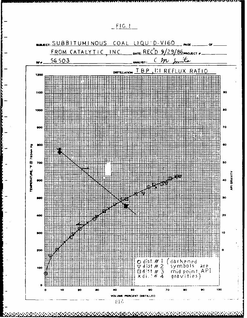
FIG. I
sJMjC:SUBB ITUM INOUS COAL L QU!D-V 160 mc___ OF _
FROM CATALYTIC INC.- DA, RECD 9 29 /8rc,.Kjc, .__
5r %503 ANALYST: C PAI 1~J; 2.STBP ,IW REFLUX RATIO
IR
-++4- 4-111 if II6A04 +I
1 4w000014 M so
11B0
910 1+++- t i____________TO__
0 tO 0 80 40 S SO 7 30 TITO
___ ___ _- _ VLL~ P~CI1DS~tED-4.-

Figure 2
DENSITY VERSUS TEMPERATURE, 3004625OF FRACTION- SUBBITUMINOUS COAL LIQUID
140 __ DesI, Tillc5010 -0.900?I I
1+1
- .". 1 .' 1.- Till 11 14 . *.~ ** *

FIG- 3
25 GALLON BATCH STILL
Rellux RatioControlGa
Distilloticn Head-
External Strip Vcu
KettleIHecte rs
B18
isNs,

-~~ 2 'Irn4
z
* m in a eon Cb 0 0 0 0
Mm PC -4 fl
't'A
Enr
0 In,
CC
r f cl
fl -
4mm
I e f" -
Ej"I

O Technical Bulletin C884
Shell Chemical Company
Shell 424 Ni/MoHydrotreating CatalystIntroduction 0 The base has been modified to make the cata-Shell 424 is a third generation nickel molybdenum lyst more tolerant to metals and contaminantscatalyst on an extruded alumina base It was devel- * Shell 424 was the first shaped catalyst Shelloped for use in severe, heavy oil services in which produced commercially The tni-lobed shapediffusional limitations may be a problem This ap- also reduces dittusional limitations This Cata-plies to all heavier than distillate feedstocks. Shell lyst has the same high strength characteristics424 provides much better activity and stability than that all Shell catalysts share, and the producttraditional Ni-Mo catalysts This catalyst diflers from has been dense loaded in nearly every applica-Shell 324 in several ways tion to date The tni-lobed shape also provides
reduced pressure drop compared with the same0 The most significant change is a totally new sized cylinder
technology for distributing the metals on the 0 The metal content was optimized for heaviercatalyst The technique provides a much more feedstockseven dispersion of metals throughout thecatalyst
Typical properties
Sh~ape I k .I{,* I, iT,,ei
Norrmai size. r i ,l 1L , I ';
Chemical composition, "',NickelMolybdenum (
Physica pwopeiessurface area. (i-o 162 *71.
Powe volume. (_ (4 (041 4; 04-Side plaft crushlivength', I Iikg) 24 (10 91 .3, 1088 4' 1,0 9Bulk crushing Strength. kg . rm 16 17 18Atirdon indes' 99. 98. %6RaNctor loding denaty, lbs/il (kg/,il
sock loaded 47-48 47-48 47 48dense loaded 52-53 52 53 52 53
Compacted bulk densely, ios II 1Jkgr'il 52 (0 83) 52 (0 f1ii !2 (0 h3)Loss of innion atO 90F (482 C), % W4 07 07 0 7
16.n~ ong fh particle'sPre'SUfr apprlied to pfoe edkurr' 0 50'oW linec, 40 mei-i'%W~f (#etanm.1iiii 0 es Mp~t ff#. t * figtnmbiui ' c 4( 11
'A,, indr ara ,jrw i
Conainr *'q -,rS) 4JOI Iii noIl
bi, 15 () It fifa

Co~ ~ ~ -I. -- 8 CI e.....Deleehyibs
VGO hydieN wMilhildiw plb'ed V Shell 424 is in service treating coker and crackedShell 424 has found immedialle acceptance through- distillates The high hydrogenation, denitrificat ionOut the industry. In less than one yer it has been activity will yield improvement in product quality atpurchased by a dozen companies in over twenty high seventy operationslocations throughout North America. It has beenextremely successful in both first-stage hydro- Packing and Jaalabi"tycrackersandVGOhydrotreaters. The diforences in Shell 424 is available as 1/16, 1/10, and 1/8 inchthe base have also allowed refiners to put a signifi- extrudates packed at 300 lbs net weight in 55 galloncant amount of residue into cat. cracker pretreaters steel drums or 1500 lbs net weight in sling binsand also to treat de-asphalted oils at relatively low Orders normally can be filled on short notice frompressures Shell 424 has improved stability and ac- inventories maintained at Shell's West Coast manu-tivity in all of these applications facturing plant Small inventories are typically kept
on the Gulf Coast for emergency or top up needs
Mid loy* ac cd-9An additional use of Shell 424 has been in mild Health, s~Ity, and environmenlMhydrocracking services. Several cat. cracker pre- pluu 4mtreaters are being used with Shell 424 to produce Shell 424 Catalyst is made from chemicals which20-30% additional distillate from VGO The distillate span a range from being practically nontoxic tohas cetane indeces between 40 and 45 depending being potential carcinogens Full attention to theseon the feedstock and cracking severity. Since the hazards, and to appropriate precautions and prevent-cracking reaction is primarily de-alkylation of poly- ative measures is essential Before ordering, testingaromatics, the bottoms product has a very low poly- or using these catalysts, available information onaromatic content and makes a superior cat cracker health, safety, and environmental hazards, precau-feed Shell 424 gives this 20-30% conversion with tions, and preventative measures must be obtainedvery low production of C4 and lighter materials from your Shell Chemical Catalyst Sales
Representative
For addtional information, call or wrte: Warranty
Shell Chemical Company All products purchased from Sh,,ii are Subject to leInS
Catalyst Business Center and conditions set out in the contract order acknowledq.,One Shell Plaza ment and/or bill of lad.riq Shell warrants only that IsPO Shell Plaa product will meet those specifications designaled as st,chP 0 Box 2463 herein or in other publications All other information sup-Houston, Texas 77252 plied by Shell is considered accurate but is furnished uporTelephone (713) 241-4997 or 241-4927 the express condition that the custorrier shall make 'Is owrl
assessment to determine the product s suitability for aparticular purpose No warranty Is expressed or impliedregardling such other information, the data upon which lhesame is based, or the results to be obtained from the useIhereof; that any product shall be merchantable ort forany particular purpose; or that the use of such otherinformation or product will not infringe any patent
fePtw -ow, ,..
B". I
_. S 5 ,, . ~. , .*.* . . .** . ,.- - -,,... . w

*, ,.,I rdvi I iinog rI'etMLJ LpLIt
Thermoucouple Well
/Threaded Hexagonal Nut
-Mounting bracket
Ceramic Ins sat on
I ii l tStainless S eel Girdle
Gas/I iquid mnl
Nichrome He, tin Elemen,\~//' / ~"Refractory
6 Zone
bo " 8' 30" \ 74 Zone
(Totl) (Rxr,. 4 " J611"
\ \ ,\ J-' Zone (T .C . Well)
, / b /
T\ 3" h
Zo e
g~ot tom
/ \ and
, i,/I AiqlI Hi (l Iv / --'- 2>K x " ketatnin
"%

cZ4Lk.,PAGE 3
2. -3,6
to*T4P 13-1 il3 L
t4I
~~e C
.111
vht -7c
Tr-
CAT
* ~ a.. 3
B2

SUSJECTPACE
Kj C-POC11 ~ or o e H1C A .0.A4
O
cec
t)
K N Ia- I 81~'
C. P. A~ TJ J -- 0

A PP EN D I X
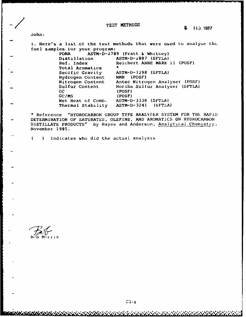
-/ TEST METHODS
john:6 F0 98
1Here's a list ot the test methods that were used to analybe thf-
fuel samples tor your program:PONA ASTM-D-2789 (Pratt & Whitney)Distillation ASTM-D-k887 (SFTLA)Ref. index Reichert ABBE MARK 11 (POSF)Total AromaticsSecific Gravity ASTM-D-1298 (SFTLA)Hydrogen Content N14R (POSF)Nitrogen Content Antec Nitrogen Analyser (POSF)Sulfur Content Horiba Sulfur Analyser (SFTLA)GC (POSF)GC/MS (POSF)Net Heat of Comb. ASTM-D-3338 (SFTLA)Thermal Stability ASTM-D-3241 (SFTLA)
*Reference "HYDROCARBON GROUP TYPE ANAL~rER SYSTEM FOR THE RAPID- DETERMINATION OF SATURATES, OLEFINS, AND AROMATICS ON HYDROCARBO0N
DISTILLATE PRODUCTS" by Hayes and Anderson, Analytical Chemistry,November 1985.
Indicates who did the actual analysis
B',b Mot i is
Cl-a
w ~ ~ ~ ~ ~ ~ ~ ~ ~ ~ ~ I A .. ~,V~ .\4 ~ ~ *W, *-

-. i-~L. FTLA- (3'. irOLI4'______ __
FLEri E PE r-!-lrl PEEFLLCU'NWCS 9_C IF I C-TIC4 J TES :4 Wo FOFIR, 14 THEJ C ~~-F'T.-r - Fjld'i-qL, FC'-.F, PL, 4;'* FfC 4
0 U EC2- T~4 Q'ETCl 4 FE , T -'E FP'FOEPT:E OF THI S S-.MPLE'- E= rIIFECTEC) TO Cl 0*ftik- GCF III FE S0.CH-i-CliER~ "T 5-.1-120.
T 4_ '01, FCgr ____UPOP
K- *: ~'ilAft~i
* 4l"-l A E -I mu.
4' '.
C22
_n.~ -

Q V22 ?1C) -
4 5 003 0. I~ltNK oC,2-q NP,
~~-4 R 3 - c LN 52-_ __ _
-7) o C)iI C) 47 2s P\ C) G '9 L4 C..
-' .4,%-~~0 C)~ E L 9 .2Lc L
1NfoO~~~~~ o-729 7___ ~ p
~]P~073or ?~O'' o.l'- i__ __ -cz____ ___ ____ __ ____ __ _ ___ __ _ ____ _ 2
2- S9# _ _ _ _i
-C, - S g- 23 :. i-- 0C7
-~~ -------- -- ~ --
I I-, I-' -o'
k- G>-Il~ -g ffc C- 3 4
190 748L~ 06 6 3&32

U
S
- I.
p
p - 5, 'b ~SP~%% 1,* %V