of talpo.it talpo€¦ · · 2017-12-02contents. page. listofplates 7 list of equipment, 9...
TRANSCRIPT

CONTENTS.
Page.
List of plates 7
List of equipment ,9
The gun:
Weights, dimensions, etc 11
Nomenclature of parts 11
Serial list of component parts of breech mechanism 12
Description of 12
Mechanism :
Action of . 14
Mounting and dismounting 15
Ammunition 16
Cartridge case 16
Primer 16
Powder charge 18
The projectile 18
Common shrapnel . 18
Frankford Arsenal combination fuze, model of 1907 M 19
Frankford Arsenal combination fuze, model of 1915 22
Base percussion fuze, medium and major caliber 23
Marking on ammunition packing boxes 23
Blank ammunition 24
The cartridge c ase 24
The primer 25
The charge 25
Preparation of blank metallic ammunition 25
Precautions to be observed 26
Care of cartridge cases 26
Reloading and cleaning outfit 27
Misfires and hangfires 27
Hand fuze setter, model of 1905 M .- 28
Range table, 12^-pound projectile t 29
Hand fuze setter, model of 1912 30
Disassembling and assembling 31
Adjusting 32
Operation'
32
Care and preservation 33
Range table, 18-pound projectile 34
Subcaliber cartridge 34
Drill cartridge 35
Subcaliber and drill cartridge kit 36
Carriage:
"Weights, dimensions, etc 37
Nomenclature of parts 37
General description of carriage 39
(5)
TALP
O.IT
TA
LPO
.IT
TALP
O.IT

Detailed description of carriage: Page.
The cradle 39
The buffer mechanism 40
Cradle axis bolt 40
Elevating gear 40
The trail 41
Theaxletree 42
The wheels 42
Dismounting and mounting gun and carriage 43
To fill buffer cylinders , 44
Care and cleaning of parts 45
Sights:
Sight model of 1912 47
Open sight 48
Panoramic sight, model of 1904 49
Panoramic sight, model of 1915 52
Use of the open sight 58
Use of the panoramic sight 58
Care of sights 58
Adjustment of sights 60
Verification of parallelism of line of sight and axis of bore 62
Additional tests 63
Tools and accessories for the gun and Carriage, description 65
The pack harness:
Description 67
Instructions for setting up the aparejo 69
Care of leather 72
The special pack equipment:Nomenclature 73
Description 73
Tools and accessaries for special pack equipment:Nomenclature 76
Description 76
Dummy pack 78
Allowance of ammunition 79
General information:
Painting artillery material 80
Oils for artillery material 81
Repairs for field artillery material 82
Suggestions for care and maintenance of material 83
Supplies in general 84
Method of loading the battery equipment on railroad cars 85
Equipment 85
Statement of total equipment for one mountain-gun battery 86
Index.. 103
TALP
O.IT
TA
LPO
.IT
TALP
O.IT

LIST OF PLATES.
Faces page.
PLATE I. 2.95-inch mountain gun ". . 11
II. Breech mechanism 12
III. Breech mechanism 14
IV. Projectiles 16
V. Combination fuze and base percussion fuze 22
VI. Handfuze setter, model of 1912 and 1905 M 28
VII. Subcaliber and drill cartridge 34
VIII. 2.95-inch mountain gun carriage 37
IX. Panoramic sight, model of 1904 49
X. Panoramic sight, model of 1915 52
XI. Aparejo, model of 1911, frame, left half 68
XII. Cradle mule 72
XIII. Wheel mule 73
XIV. Trail mule 74
XV. Gun mule 75
XVI. Pioneer tools (roll open) 74
XVII. Pioneer tools (roll closed). 75
XVIII. Blacksmith's roll 74
XIX. Supply mule 75
XX. Saddler's tool kit 74
XXI. Signal mule 75
XXII. Carpenter's tool kit ..." 76
XXIII. Special pack equipment 77
XXIV. Schaller forge, model of 1910 78
XXV. Blacksmith's tool kit 79
(7)
TALP
O.IT
TA
LPO
.IT
TALP
O.IT

TALP
O.IT
TA
LPO
.IT
TALP
O.IT

Part I (a). THE GUN, AMMUNITION, AND ACCOMPANYINGPARTS.
The gun, weights, dimensions, etc.
Weight of gun, including breech mechanism pounds. . 236
Caliber inches. . 2. 953
Total length do. ... 35. 85
Length of bore, including chamber :. ,1do 31 . 6
Length of rifled portion of bore do. ... 24. 33
Rifling, uniform. 1 turn in 25 calibers, right-hand twist:
Number of grooves 30
Width of grooves inch. . . 23
Depth of grooves do . 023
Capaci1
y of powder chamber cubic inches. .
'
34. 9
f 1 2 5Wei ;:ht of projectiles. . . pounds. .
-Lg'
Weight of powder charge (N. (\ smokeless):
For 12i-pound projectile ounces. . 8
For 18-pound projectile do . 7
Weight of cartridge case pounds. . 1. 45
Mu/zle velocity:
J 2.1 -pound projectile feet per second . . 920
18-pound projectile do 750
Maximum chamber pressure pounds per square inch. . 18, 000
Nomenclature of parts of gun.
Part. Description or location. Class. Section.
Body With lugs for carrier and piston rods integralGuide button Screwed into barrel underneath : . .
Eyebolt On rear of barrel, interchangeable with eyebolt oncradle.
Breechbloclc In breech of gunPallet, hardened steel Attached to breechblock with 2 screws
Fixing screw Secures cockjng cam in breechblockCarrier Pivoted to breech of gun bodyCarrier axis pin With split pin fixes carrier to gunCocking cam In breechblockExtractor Pivoted to breech near carrier hingeExtractor axis pin With split pin fixes extractor to gunFiring pin In center of breechblock
Firing-pin point Screwed into firing pinGuide plate On rear of breechblockHand lever Pivoted to carrier IVHand-lever axis pin With split pin fixes lever to carrier
Hand-lever catch Locks hand lever in closed position to carrier
Hand-lever catch spring !Actuates hand-lever catch. I
Hand-lever catch pivot Special split pinLocking bolt .' In a recess in the carrier
Locking-bolt rivet Secures the locking-bolt spring to bolt
Lock ing-bolt spring Actuates the locking bolt
Mainspring Coiled spring in firing pinTrigger sear Pivoted in carrier
Trigger sear spring Returns the trigger sear to engagementTrigger, complete, consisting
of--
Trigger Assembled in breech of barrel, left side
Trigger lever With split pin, has an eye for lanyardTrigger spring Coiled spring on trigger
(ID
TALP
O.IT
TA
LPO
.IT
TALP
O.IT
''
"' v< /""'/
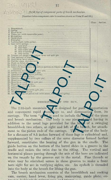
7'-list of component parts of breech mechanism.
[Numbers before components refer to numbers shown on Plates II and III.]
Class. Section.
1 . Breechblock2. Carrier3. Hand lever .
4. Firing pin (with removable point) :
5. Mainspring6. Guide plate7. Extractor8. Locking bolt (with spring)9. Sear (with spring)
9a. Sear stud,.
9?). Sear bent9c. Sear safety arm9d. Sear actuating arm9e. Sear spring
10. Trigger and spring with trigger lever and split pin11. Gear segment of breechblock12. Hand-lever bevel pinion13. Cocking piece, showing cams IV14. Studs on firing pin15. Safety groove in breechblock16. Groove in breechblock in which projection on trigger-sear safety arm travels during
unlocking17. Protection on trigger-sear safety arm18. Carrier axis pin (with split pin)19 Hand-lever catch (lower portion)20. Hand-lever axis-pin lugs21. Hand-lever axis pin (with split pin)22. Hand -lever stop23^-Hand-lever catch (with split pin)24. Hand-lever catch spring :
25. Firing-pin recocking hook26. Firing-pin bent :
27. Extractor axis pin (with split pin)28. Short arm of extractor29. Spring catches for piston rod (with screw, washer, and spring)
DESCRIPTION OF THE GUN.
The 2.95-inch mountain gun is designed for pack transportationand consequent rapid assemblage to, and dismounting from, its
carriage. The term "gun" is used to include the body of the piece
and breech mechanism. The body is one piece of steel having in
addition to the usual lugs provided for the hinge of a swingingbreechblock two others, at right and left of the breech, for attach-
ment to the piston rods of the carriage. The exterior of the bodyfor a distance of 8.5 inches forward of these lugs is cylindrical and,
supplemented by two collars of the same diameter formed farther
forward, constitutes the bearing of the gun in the cradle. The
guide button on the bottom of the barrel slides in a groove in the
cradle and resists the twist due to the rifling. The vertical and
horizontal planes passing through the axis of the bore are indicated
on the muzzle by the grooves cut in the metal. Fine threads or
wires may be stretched across in these grooves to make a front
bore sight for use in verifying sights, etc. An eyebolt is threaded
into the body at the breech for lifting the gun.The breech mechanism consists of the breechblock and cocking
cam, carrier, hand lever, firing pin, mainspring, guide plate, ex-
tractor, locking bolt, trigger sear, and trigger.
TALP
O.IT
TA
LPO
.IT
TALP
O.IT

REAR VIEW BREECH (CLOSED) plate
TALP
O.IT
TA
LPO
.IT
TALP
O.IT

TALP
O.IT
TA
LPO
.IT
TALP
O.IT

13
Breechblock. The breechblock locks into the body with an inter-
rupted screw. The center of the block is chambered in front for the
firing pin and in rear for the cocking cam, the latter being separate
from the block for manufacturing reasons only and solidly secured to
it by two lugs and the fixing screw. In the rear face of the breech-
block are cut two concentric grooves and with the partition between
them cut away in two places to allow the projection on the end of the
safety arm of the sear which engages these grooves to pass from one
to the other. On the rear face of the breechblock is a circular toothed
segment which is engaged by the segmental bevel pinion of the hand
lever. There is also a recess on the rear face of the block lined with
a hardened steel pallet into which the locking bolt enters when the
block is revolved sufficiently to disengage the interrupted threads;
the locking bolt then preventing further rotation of the block while
moving with the carrier in and out of the breech.
< (irricr. The carrier which holds the breechblock is pivoted to the
right side of the breech by the carrier axis pin. It is bored partly
through and threaded to engage the continuous threads at the rear
end of the breechblock. A reduced bore passes through the carrier
and receives a boss on the guide plate. A recess on the inner or
front face receives the locking bolt and its spring, which is secured to
the locking bolt by a rivet;a recess in the lower hand-lever axis-pin
lug on the carrier engages the hand-lever catch, thereby securing the
hand lever when the breech is closed. On the rear face of the carrier
are two lugs. The hand-lever axis pin passes through holes in these
and through a hole in the guide plate which it secures in place.
Between the two lugs is a slot which embraces the stud on the rear
face of the trigger sear.
Hand lever. The hand lever is pivoted to the carrier by the hand-
lever axis pin. The handle or grip is recessed to receive the hand-
lever catch, which is pivoted in the hand lever by a large split pin
(hand-lever catch pivot), a leaf spring (hand-lever catch spring) beingseated in the catch to insure its engagement when the breech is closed.
The segmental bevel pinion of the hand lever is concentric with the
axis pin and engages the toothed segment of the breechblock. Whenthe hand lever has been pulled around on its axis until the breech-
block is properly disengaged, a projection on the hand lever adjoiningthe pinion contacts with the rear face of the block and preventsfurther rotation of the hand lever. The hand levers that weremanufactured at Watervliet Arsenal are not interchangeable withthose of guns purchased from Vicker's Sons & Maxim.
Firing pin. The firing pin is a hollow sleeve provided with two
lugs which ride upon the cam surfaces of the cocking cam. A hook,which extends to the rear through recesses in the carrier and the guide
plate, prevents the firing pin from turning when the breechblock is
TALP
O.IT
TA
LPO
.IT
TALP
O.IT

14
rotated and makes recocking possible without opening the breech.
Near the rear end of the body of the firing pin the metal is cut away,
forming a bend or notch into which an arm of the trigger sear drops.The firing-pin point is screwed into the firing pin and is replaceable.
Mainspring. The mainspring is a helical spring which fits inside
the hollow in the center of the firing pin and into a recess in the
guide plate. The guide plate retains it in place.
Guide plate. The hand-lever axis pin passes through a hole in the
guide plate, thus retaining it in position. The guide plate is recessed
to receive the mainspring, and recesses on the sides allow the recock-
ing hook of the firing pin and the sear stud to pass through.Extractor. The extractor is, pivoted near the carrier hinge on the
extractor-axis pin. At the end of the extracting arms are claws
which engage with the rim of the cartridge. It is actuated by the
carrier striking against its short arm just before the breech is fully
open.
Locking bolt. The locking bolt fits in a recess in the front face of
the carrier. When the breechblock is fully rotated ready to swing
out, a recess formed in it comes opposite the bolt, which latter, acted
on by its spring, moves forward and locks the block to the carrier.
The locking-bolt spring is secured to the locking bolt by a rivet.
Trigger sear. The trigger sear is pivoted to the carrier by meansof a stud which fits in a groove in the center of the carrier and is
secured there by the guide plate. Safety during loading is provided
by means of the arm, which has a projection at its outer extremitywhich engages in the groove during the period when the breechblock
is being locked. While this projection is in this outer groove the
firing pin is engaged by the sear, so that the firing pin can not moveforward and strike the primer. The sear has also another arm the
outer end of which lies above the trigger lever when the breech-
block is home. The arm has the sear spring attached to it, which
causes the sear to engage the firing pin in the cocked position.
Trigger. A square shaft on the trigger passes through a squarehole in the trigger lever and is held in place by a split pin. The
trigger is fitted in the breech of the gun ;the trigger lever terminates
in a loop to which a lanyard can be attached. When this is pulledthe trigger revolves, causing the trigger to lift up the arm of the sear
and so release the firing pin from the sear. The trigger is kept in
its normal position by the small spring called the "trigger spring."
ACTION OF MECHANISM.
On grasping the handle of the hand lever the hand-lever catch is
pressed in and its lower extremity thereby moved clear of the recess
in the lower hand-lever axis-pin lug so that the hand lever is ur locked.
On moving the handle to the right the bevel pinion thereon causes the
TALP
O.IT
TA
LPO
.IT
TALP
O.IT

TALP
O.IT
TA
LPO
.IT
TALP
O.IT

TALP
O.IT
TA
LPO
.IT
TALP
O.IT

TALP
O.IT
TA
LPO
.IT
TALP
O.IT

29
For setting the 15-second combination fuze, a number of which
are still in the service, a suitable punch is provided. With this puncha hole is made through the cover, time train, and lead cone of the
fuze at the point corresponding to the number of seconds desired.
Range table for 2.95-inch mountain gun.
PROJECTILE, 12 POUNDS. MUZZLE VELOCITY, 920 FEET PER SECOND.
!
TALP
O.IT
TA
LPO
.IT
TALP
O.IT

30
HAND FUZE SETTER, MODEL OF 1912.
[Plate VI.]
The hand fuze setter is provided for the same purpose as the handfuze setter, model of 1905 M. Plate VI shows assembled and sectional
views and designation of parts. The principal parts are the case, the
range-index mechanism, range mechanism, correction mechanism, and
guide plate.
The case forms a housing for the movable parts and provides seats
for the worm cases and the index bar. The slot cut in the top of the
case limits the movement of the projecting segment of the corrector-
scale support, which carries the corrector scale. The serrated rim
forms a handle for turning. The arrow engraved upon the top and
the lower center edge of the case coincides with the graduations of the
corrector scale. Two oil-hole screws are located in the case directly
under the serrated rim on both right and left sides and identified bythe word "Oil."
The range-index mechanism consists principally of the index bar,
range index, index plunger, and index spring. The index bar is
retained in its seat, located in the case directly above the range ringand corrector scale, by two index-bar screws, and forms a slide for the
range index. The V-shaped notches in the index bar are markedwith numbers 1, 2, and 3, with the word "Zone." The range index
sliding upon the index bar is held in position by the index spring,
forcing the index plunger into the V-shaped notches of the index bar.
The range mechanism consists principally of the range ring, range-
ring carrier, worm, worm case, worm-adjusting screw, and wormknob.
The correction mechanism consists principally of the corrector
S3ale, corrector-scale support, worm, worm case, worm-adjusting
screw, and worm knob.
The range ring is located upon the range-ring carrier by a steel
dowel pin and secured in position by three range-ring screws. Thessale is graduated for a range of 4,900 yards, least division is 50
yards, and numbered every 500 yards.The data for graduating the range ring is computed from actual
corrected firings, and then corrected for a suitable height of burst of
3 mils. The graduated surface is sandblasted and lacquered.The corrector scale is mounted upon the projected segment of the
corrector-scale support and secured by two corrector-scale screws.
On this scale is graduated 120 equal divisions, 50 minutes apart,numbered every 10 divisions. Graduation numbered 30 is the nor-
mal or zero position, and is indicated by an arrow. The word " Turn' '
and an arrow engraved upon the corrector scale indicates the direc-
tion the fuze setter must be turned when setting a fuze. A pointer
TALP
O.IT
TA
LPO
.IT
TALP
O.IT

31
is riveted and soldered to the top of the corrector scale in a certain
position to coincide with the graduated line on the closing cap of the
fuze.
The range-ring carrier is seated in the corrector-scale support. Theworm teeth mesh with the threads of the worm on the right side of
the fuze setter. The slot, which is cut in the bottom side of the
range-ring carrier, engages with the rotating pin in the graduatedtime train ring of the fuze. The interior is conical in shape, to suit
the exterior of the fuze.
The corrector-scale support is held within the case by the guide
plate. The worm teeth mesh with the threads of the worm on the
left side of the fuze setter. The movement of the corrector-scale
support is limited in both directions by the slot in the case. The
stop pin is secured in the interior of the corrector-scale support bythe stop-pin screw, and engages with the fixed stop pin in the bodyof the fuze to limit the movement of the fuze setter.
The worms are mounted eccentrically in the worm cases, which,when turned, provides an adjustment to take up the wear betweenthe worm teeth of the range-ring carrier or corrector-scale supportand the threads of their respective worm. The worm cases havescrew-driver slots at their rear ends, which are provided for adjust-
ing, and are locked in position by the worm-case clamp plugs, whichare secured by the worm-case clamp screws. The worm-adjustingscrews have fiber washers fitted in their ends that bear upon the
collars of the worms for taking up end motion and to provide suf-
ficient friction to resist accidental turning. A screw-driver slot is
located at their front end for adjusting. The worm-adjusting screws
are locked in position by the worm-adjusting screw clamp plugswhich are secured by the worm-adjusting screw clamp screws. Theworm knobs are secured to the worms by taper pins. The exterior
of the worm knobs is straight knurled to facilitate turning. The
guide plate is screwed in its threaded seat in the bottom of the case
and retained in position by the guide-plate lock screw.
DISASSEMBLING AND ASSEMBLING.
To disassemble, remove the index-bar mechanism, which is held in
place by two index-bar screws. Take out the three range-ringscrews and the two corrector-scale screws and remove the range ringand the corrector scale. Remove the guide-plate lock screw andunscrew the guide plate, using a teat wrench. To remove the wormknobs from the worms, drive out the taper pins. Loosen the worm-
adjusting screw clamp screws, which release the worm-adjustingscrew clamp plugs. Remove the worm-adjusting screws. Theworms can now be removed by turning. The corrector-scale support
TALP
O.IT
TA
LPO
.IT
TALP
O.IT

32
and range-ring carrier can then be removed. To remove the worm
cases, loosen the worm-case clamp screws, which release the worm-case clamp plugs.
Assemble in reverse order.
ADJUSTMENT.
Backlash or lost motion may appear between the collars of the
worms and the fiber washers endwise; between the worm teeth of
the range-ring carrier or the corrector-scale support and the threads
of their respective worms.
To remove the end backlash, loosen the worm-adjusting screw
clamp screw, which releases the worm-adjusting screw clamp plug;then turn the worm-adjusting screws clockwise, using a screw driver r
until the end play is removed and there is sufficient friction to preventaccidental turning of the worms. The worm-adjusting screw clamp
plugs must be firmly clamped after adjusting by tightening the
worm-adjusting screw clamp screws, which secures the worm-adjust-
ing screws against rotation.
Should backlash appear between the worm teeth of the range-ringcarrier or the corrector-scale support and the threads of their respec-tive worms, it can readily be removed by loosening the worm-case
clamp screws, which release the worm-case clamp plugs, and then
turning the worm cases, using a screw driver in the slot at the rear
end, in which the worms are eccentrically mounted, so as to bringthe worms in closer contact with the worm teeth. The worm-case
clamp plugs must be firmly clamped after adjusting by tighteningthe worm-case clamp screws which secures the worms cases againstrotation.
OPERATION.
First. Turn the worm knob, pinned to the worm and located at
the front-right side of the fuze setter, until the desired range on the
range ring registers with the range index.
Second. Turn the worm knob, pinned to the worm and located at
the front-left side of the fuze setter, until the graduated line on the
corrector scale, which indicates the desired correction for height of
burst, registers with the engraved arrow on the case.
The graduation, numbered 30 and indicated by an arrow head, is
the normal height of burst under normal conditions. A decreased
reading on the corrector scale decreases the height of burst and in-
creases the range, and increased reading increases the height of burst
and shortens the range.To set a fuze, remove the waterproof cover, place the fuze setter
over the fuze and turn until the slot in the bottom of the range-ringcarrier engages with the rotating pin in the graduated time train
TALP
O.IT
TA
LPO
.IT
TALP
O.IT

33
ring of the fuze. The guide plate and conical interior of the range-
ring carrier will then rest upon the fuze. Turn the fuze setter clock-
wise, as indicated by the arrow on the corrector scale, until the stop
pin fastened to the corrector-scale support engages with the, fixed
stop pin in the body of the fuze and further motion is prevented.
The pointer, which is attached to the top of the corrector scale,
should register with the graduated line on the closing cap, to indi-
cate that the stop pin of the fuze setter and the fixed-stop pin of
the fuze are in contact. This pointer is added as the graduated time
train ring of the fuze has tendency to stick or to bind to such a de-
gree as to indicate that the stop pin of the fuze setter and the fixed-
stop pin of the fuze are in contact.
Cards for recording the results of tests of the fuze setters are fur-
nished by the Ordnance Department for each size of gun, howitzer,
or mortar, on which computed problems of inspection are given as
indicated below. The examples given below are for 2.95-inch
mountain gun. The cards for other calibers are similar.
Rangering.
TALP
O.IT
TA
LPO
.IT
TALP
O.IT

Range table for 2.95-inch mountain gun.
PROJECTILE, 18 P0I?Ni?S. MUZZLE VELOCITY, 750 FEET PER SECOND.TA
LPO
.IT
TALP
O.IT
TA
LPO
.IT

TALP
O.IT
TA
LPO
.IT
TALP
O.IT

TALP
O.IT
TA
LPO
.IT
TALP
O.IT
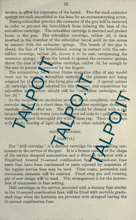
35
motion to allow for expansion of the barrel. Two flat steel extractor
springs are each assembled to the base by an extractor-spring screw.
During subcaliber practice the extractor of the gun will be removedin order to prevent the breechblock from defacing the base of the
subcaliber cartridge. The subcaliber cartridge is inserted and pushedhome in the gun. The subcaliber cartridge, caliber .30, is then
inserted in the chamber of the subcaliber barrel until its rim comesin contact with the extractor springs. The breech of the gun is
closed, the face of the breechblock coming in contact with the sub-
caliber cartridge, caliber .30, shoves it to its seat, compressing the
extractor springs. When the breech is opened the extractor springsthrow the case of the subcaliber cartridge, caliber .30, far enough to
the rear to permit its removal by the fingers.
The ammunition for United States magazine rifles of any modelmust not be used in subcaliber cartridges, the primers not being
adapted for the blow of the firing pins of cannon. A special caliber
.30 cartridge has been adopted for this purpose, and requisitions for
subcaliber ammunition should call for" subcaliber cartridges, cali-
ber .30."
As the residue from smokeless powder, if not completely removed,corrodes the bore in a short time, the subcaliber cartridges should be
carefully cleaned after use. The bore should be cleaned with a ragsaturated with soda water (one-half pound sal soda to 1 gallon boiling
water) and wiped thoroughly dry with a clean rag. Then oil the bore
with a light coating of light slushing oil or other suitable oil.
DRILL CARTRIDGE.
[Plate VII.]
The "drill cartridge" is a dummy cartridge for use in drilling can-
noneers in the service of the -gun. It is a bronze casting of the shapeof the service shrapnel ammunition and is fitted at the point with a
Frankford Arsenal 21-second combination fuze. Burned-out fuze
parts that have been condemned or parts rejected by inspectors of
the regular service fuze may be used. Time trains, percussion and
concussion elements will be omitted. Fixed stop pin and rotating
pin of new design will be used. This arrangement is for the instruc-
tion of cannoneers in fuze setting.
Drill cartridges in the service, provided with a dummy fuze similar
to the 15-second combination fuze, will be fitted with movable gradu-ated rings when the batteries are provided with shrapnel having the
21-second combination fuze.
TALP
O.IT
TA
LPO
.IT
TALP
O.IT

36
SUBCALIBER AND DRILL CARTRIDGE KIT.
The subcaliber and drill cartridge kit consists of:
3 drill cartridges.
1 subcaliber cartridge.
2 extractor springs.
2 extractor-spring screws.
1 cleaning rod.
1 eyepiece.
1 extension piece.
1 graduated time-train ring.
1 time-train ring.
1 locking-shoe set screw.
1 locking shoe.
1 bristle cleaning brush.
1 pin wrench.
1 storage chest.
3 rotating pins with locking pins.
1 closing cap.
1 closing-cap set screw.
1 closing cap wrench.
3 fixed stop pins with screws.
One subcaliber and drill cartridge kit is issued for each gun.
TALP
O.IT
TA
LPO
.IT
TALP
O.IT

TALP
O.IT
TA
LPO
.IT
TALP
O.IT

TALP
O.IT
TA
LPO
.IT
TALP
O.IT

Part I (b). THE 2,95-INCH MOUNTAIN-GUN CARRIAGE ANDSIGHTS,
Weights, principal dimensions, etc.
Weight of carriage pounds. . 595
Weight of gun and carriage do 830
Diameter of wheels inches. . 36
Width of track do 32
Length of recoil of gun on carriage do 14
Height of axis of gun do 26
Maximum angle of elevation degrees. . 27
Maximum angle of depression do 10
Amount of traverse of gun on carriage do
Nomenclature of parts of the carriage.
Name of part.
TALP
O.IT
TA
LPO
.IT
TALP
O.IT

38
Nomenclature of parts of the carnage Continued.
No.
TALP
O.IT
TA
LPO
.IT
TALP
O.IT

TALP
O.IT
TA
LPO
.IT
TALP
O.IT

106
H.Vuge.
Halter bridle, model of 1910, description 67, 86
Hand lever, description 13
Handspike, description 66, 91
Handspike key, location 38, 42
I.
Individual equipment, list of 94
Instruction plate, function 37, 40
L.
Lair rope Mj
Lash cincha, description 75, 89
Leather:
Black, care of 72
Russet, care of 72
Reasons for oiling 72
Lash rope, description 73, 88
Lifting bar, description 76. 90
Linch pin, description 37, 42
Load strap, function 75, 88
Loading of battery equipment on railroad cars 85
Locking bolt, description 14
M.
Marking outfit, list of 96
Mainspring, description. 14
Material?
Cleaning and preserving, 6 months' allowance, list of 98, 99
Saddler's allowance. 6 months, list of 99, 100
N.Name plate, description 38, 42
O.
Oil, for recoil cylinder 44. 45
Oil can case carrier, location 38, 42
Oils for artillery mate'riel 81
Open sight:
Care 58
Description 48
Use 58
P.Pack covers, description 73, 89
Pack frame, model of 1912, description 73-74, 88
Pack frame, heavy, description 73, 88
Pack harness, parts in 67, 87
Painting artillery mate'riel 80, 81
Panoramic sight, model of 1904:
Care 58, 59
Description 49
Use 58
Panoramic sight, model of 1915:
Care 58. 59
DescriptionUse.. 58
TALP
O.IT
TA
LPO
.IT
TALP
O.IT

107
Page.
Picket pin and eye, function 76, 92
Picket-rope section, description 76, 92
Pioneer's rolls, description , 77-89
Piston head, location 37, 40
Piston lock, function 37, 40
Piston rod:
Description. 32, 40
To remove from buffer cylinders 44
To replace in buffer cylinders 44
Piston rod handle 37
Piston-rod packing, location 37, 40
Plates, arrow 37, 40
Plates, list of 7
Pouch for spare parts, description 78, 91
Powder charge, composition of 18
Primer, general description of 16, 25
Primer, 110-grain percussion:
Description 17
Action 17
Primer, saluting, care in use of 25
Projectiles 18
R.
Range-finding and fire-control equipment 94
Range table for 12^-pound projectile 29
Range table for 18-pound projectile 34
Reloading and cleaning outfit:
Parts in 27
Use of parts in 27
Repairs for field-artillery materiel 82
Reserve supply for war service, list of 101
Rigging cover, description 76, 92
Riveting, instruction for 82, 83
Rope 92
S.
Saddle blanket, description 68, 86
Saddler's tools, list of : - 98
Saddler's tool kit 78
Saluting primer percussion, description 25
Schaller forge, description 77, 97
Schaller-forge tool chest, description 77, 97
Scraper, location - - - 38, 41
Shell, 12^-pound, description 18
Shell, 18-pound, description IS
Shoe, description 38, 41
Shoe handle, location 38. 42
Shrapnel, earlier design, description
Shrapnel, common.
Description 1&
Action 19
Side plates, description 38, 41
Sight-bracket base, location 37, 39
Sight case, description 66, 91
Sight chest, spare 76, 89
TALP
O.IT
TA
LPO
.IT
TALP
O.IT

108
Page.
Sight, model of 1912 47
Sight scroll gear 47
Sight shank, description 47
Sight-shank range strip 48
Sight-shank socket, description 48
Sling rope 73, 89
Sobrejalma, model of 1910, description 68, 69
Spare parts :
For carriage, list of 91
For gun, list of 91
For hand fuze setter 93
Slight 91
For special pack equipment 93
Special pack equipment 73, 88
Subcaliber and drill cartridge kit, contents 36, 96
Subcaliber cartridge :
Ammunition used 35
Care 35
Description 34
Supply chest, saddler's 76, 89, 92
Supply chest, blacksmith's 76, 89, 92
Supply chest, miscellaneous 76, 89, 92
Supply chest, tools 78, 92
Supplies in general 84, 85
Support, function 38, 41
Supporting plates 38, 42
T.
Targets 79
Thongs 73,89
Tools:
For gun and carriage, list of 91
For special pack equipment . 76, 92
Tool pockets, description 66, 91
Trail, description - 38, 41
Trail pad, description - 74, 88
Transoms, front and rear - 38, 41
Trigger, description
Trigger sear, description
Tubular oil can, description . 66, 91
Tubular oil can carrier, description 66, 91
W.Wheels:
Care and precautions
Description 38, 42
Dismounting 43
Mounting 43
Wheel hanger, description- 74, 88
Wheel tie strap, description 74, 88
June 10, 1912.
Revised September 15, 1916.
Form No. 1761.
Ed. Sept. 1-M6 s<)0.
TALP
O.IT
TA
LPO
.IT
TALP
O.IT