ohiobrass - 26-hilite insulators
DESCRIPTION
Ohio Brass Hi Lite InsulatorsTRANSCRIPT
7/16/2019 OhioBrass - 26-HiLite Insulators
http://slidepdf.com/reader/full/ohiobrass-26-hilite-insulators 1/36
26-
OHIO BRASS – WADSWORTH, OHIO MAY 2004
® ®
POWER SYSTEMS, INC.
Printed in USA
Sect
26
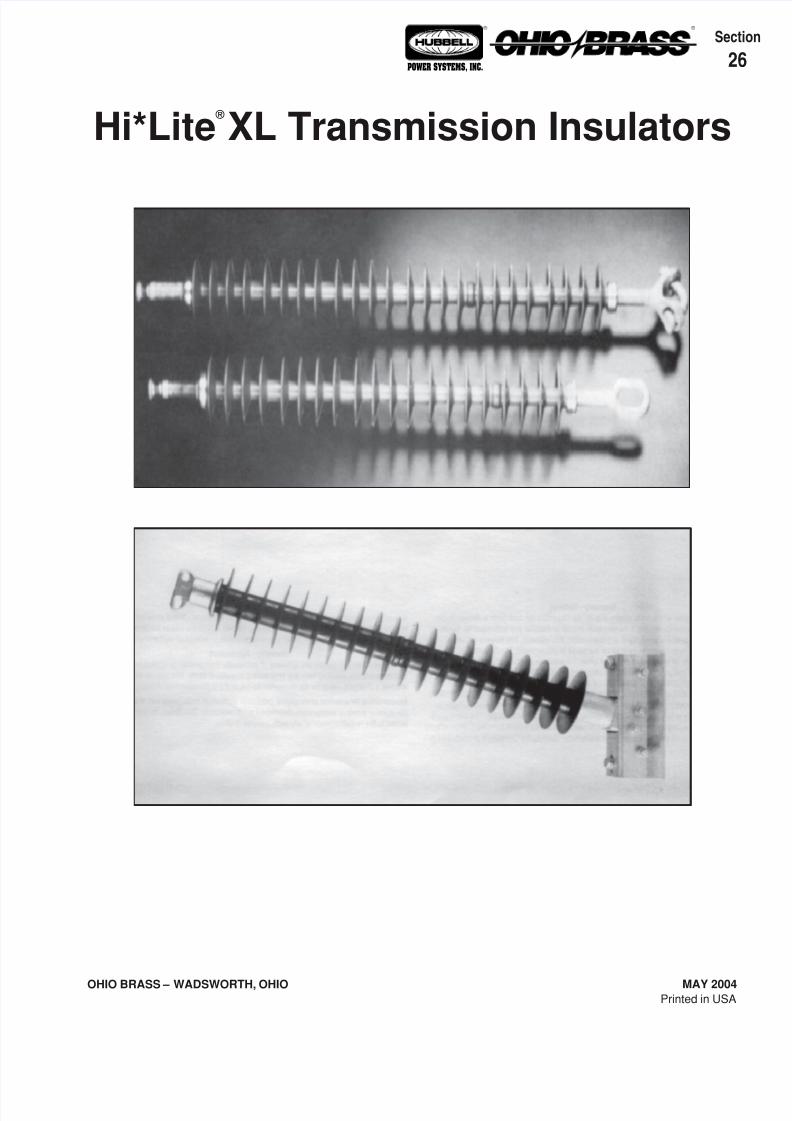
Hi*Lite ®
XL Transmission Insulators
7/16/2019 OhioBrass - 26-HiLite Insulators
http://slidepdf.com/reader/full/ohiobrass-26-hilite-insulators 2/36
OHIO BRASS – WADSWORTH, OHIO
26-2
MAY 2004
® ®
POWER SYSTEMS, INC.
© Copyright 2004 Hubbell/Ohio Brass • 8711 Wadsworth Road • Wadsworth, OH 44281
NOTE: Because Hubbell has a policy of continuous product improvement, we reserve the right to change design and specifications without notice.
Warranty - MaterialHubbell Power Systems, Inc. warrants all products sold by it to be merchantable (as such term i sdefined in the Uniform Commercial Code) and to be free from defects in material and
workmanship. Buyer must notify the Company promptly of any claim under this warranty. The
Buyer's exclusive remedy for breach of this warranty shall be the repair or replacement, F.O.B.factory, at the Company's option, of any product defective under the warranty which is returned
to the Company within one year from the date of shipment. NO OTHER WARRANTY, WHETHEREXPRESS OR ARISING BY OPERATION OF LAW, COURSE OF DEALING, USAGE OF
TRADE OR OTHERWISE IMPLIED, SHALL EXIST IN CONNECTION WITH THE COMPANY'S
PRODUCTS OR ANY SALE OR USE THEREOF. The Company shall in no event be liable forany loss of profits or any consequential or special damages incurred by Buyer. The Company's
warranty shall run only to the first Buyer of a product from the Company, from the Company's
distributor, or from an original equipment manufacturer reselling the Company's product, and is
non-assignable and non-transferable and shall be of no force and effect if asserted by anyperson other than such first Buyer. This warranty applies only to the use of the product as
intended by Seller and does not cover any misapplication or misuse of said product.
Warranty - ApplicationHubbell Power Systems, Inc. does not warrant the accuracy of and results from product or
system performance recommendations resulting from any engineering analysis or study. This
applies regardless of whether a charge is made for the recommendation, or if it is provided freeof charge.
Responsibility for selection of the proper product or application rests solely with the purchaser. In
the event of errors or inaccuracies determined to be caused by Hubbell Power Systems, Inc., itsliability will be limited to the re-performance of any such analysis or study.
7/16/2019 OhioBrass - 26-HiLite Insulators
http://slidepdf.com/reader/full/ohiobrass-26-hilite-insulators 3/36
26-
OHIO BRASS – WADSWORTH, OHIO MAY 2004
® ®
POWER SYSTEMS, INC.
Hi*Lite ® Transmission Insulators
Suspensions
Line Posts
Braced Posts
Station Posts
Sample Polymer Specs
Section
26
7/16/2019 OhioBrass - 26-HiLite Insulators
http://slidepdf.com/reader/full/ohiobrass-26-hilite-insulators 4/36
OHIO BRASS – WADSWORTH, OHIO
26-4
MAY 2004
® ®
POWER SYSTEMS, INC.
7/16/2019 OhioBrass - 26-HiLite Insulators
http://slidepdf.com/reader/full/ohiobrass-26-hilite-insulators 5/36
26-
OHIO BRASS – WADSWORTH, OHIO MAY 2004
® ®
POWER SYSTEMS, INC.
®
Table of ContentsPage
Design ..............................................................26-6
Rod...................................................................26-6
End Fittings ......................................................26-6
Weathersheds ..................................................26-6
Interface ........................................................... 26-6
Leakage Distance ............................................26-6
Washability .......................................................26-6
Mechanical Ratings ..........................................26-6Lengths Available .............................................26-6
Product Updates ..............................................26-6
Packaging ........................................................26-6
Corona Performance ........................................26-7
Hi*Lite XL 25k SML Data .................................26-8
Hi*Lite XL 30k SML Data .................................26-9
Hi*Lite XL 50k SML Data ...............................26-10
End Fitting Detail ............................................26-11
Key to the Catalog Numbers ..........................26-11
Hi*Lite II 80k SML Data ..................................26-12
Hi*Lite XL
Suspension Insulators
7/16/2019 OhioBrass - 26-HiLite Insulators
http://slidepdf.com/reader/full/ohiobrass-26-hilite-insulators 6/36
OHIO BRASS – WADSWORTH, OHIO
26-6
MAY 2004
® ®
POWER SYSTEMS, INC.
Hi*Lite ®
XL InsulatorsHi*Lite XL suspension insulators in this publicationembody the latest features available in polymerinsulator design and manufacture.
From the early prototypes in 1971, through full scaleintroduction in 1976, and through the succeedingyears, Hi*Lite insulators have featured conservativedesign and high-quality manufacture.
Today’s Hi*Lite insulators will add to the over1,000,000 already in service worldwide.
Design
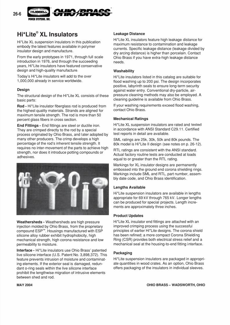
The structural design of the Hi*Lite XL consists of thesebasic parts:
Rod - Hi*Lite insulator fiberglass rod is produced fromthe highest quality materials. Strands are aligned for
maximum tensile strength. The rod is more than 50percent glass fibers in cross section.
End Fittings - End fittings are steel or ductile iron.They are crimped directly to the rod by a specialprocess originated by Ohio Brass, and later adopted bymany other producers. The crimp develops a highpercentage of the rod’s inherent tensile strength. Itrequires no inter-movement of the parts to achieve highstrength, nor does it introduce potting compounds oradhesives.
Weathersheds - Weathersheds are high pressure
injection molded by Ohio Brass, from the proprietarycompound ESP™. Housings manufactured with ESPsilicone alloy rubber exhibit hydrophobicity, highmechanical strength, high corona resistance and lowpermeability to moisture.
Interface - Hi*Lite insulators use Ohio Brass’ patentedlive silicone interface (U.S. Patent No. 3,898,372). Thisfeature prevents intrusion of moisture and contaminat-ing elements. If the exterior seal is damaged, redun-dant o-ring seals within the live silicone interfaceprohibit the lengthwise migration of intrusive elementsbetween shed and rod.
Leakage Distance
Hi*Lite XL insulators feature high leakage distance formaximum resistance to contamination and leakagecurrents. Specific leakage distance (leakage divided bydry arcing distance) is higher than porcelain. Contact
Ohio Brass if you have extra-high leakage distanceneeds.
Washability
Hi*Lite insulators listed in this catalog are suitable forflood washing up to 200 psi. The design incorporatespositive, labyrinth seals to ensure long-term securityagainst water entry. Conventional dry-particle, air-pressure cleaning methods may also be employed. Acleaning guideline is available from Ohio Brass.
If your washing requirements exceed flood washing,contact Ohio Brass.
Mechanical Ratings
Hi*Lite XL suspension insulators are rated and testedin accordance with ANSI Standard C29.11. Certifiedtest reports in detail are available.
SML ratings are 25k, 30k, 50k and 80k pounds. The80k model is Hi*Lite II design (see notes on p. 26-12).
RTL ratings are consistent with the ANSI standard.Actual factory routine tests are conducted at loadsequal to or greater than the RTL rating.
Markings for XL insulator designs are permanently
embossed into the ground end corona shielding rings.Markings include SML and RTL, part number, assem-bly date code, and Ohio Brass identification.
Lengths Available
Hi*Lite suspension insulators are available in lengthsappropriate for 69 kV through 765 kV. Longer lengthscan be produced for special projects. Length incre-ments are approximately three inches.
Product Updates
Hi*Lite XL insulator end fittings are attached with an
improved crimping process using the successfulprinciples of earlier Hi*Lite designs. The corona shieldhas been refined; a more compact Corona ShieldingRing (CSR) provides both electrical stress relief and amechanical seal at the housing-to-end fitting interface.
Packaging
Hi*Lite suspension insulators are packaged in appropri-ate quantities in wood crates. As an option, Ohio Brassoffers packaging of the insulators in individual sleeves.
7/16/2019 OhioBrass - 26-HiLite Insulators
http://slidepdf.com/reader/full/ohiobrass-26-hilite-insulators 7/36
26-
OHIO BRASS – WADSWORTH, OHIO MAY 2004
® ®
POWER SYSTEMS, INC.
Normal Applications: Top Grounded, Bottom Energized500 kV
Rings
271761-3001271751-3001
271761-3002271751-3002
345 kV
Ring
NONE271705-3001
NONE271705-3002
230 kV
Ring
NONE271761-3001
NONE271761-3002
Orientation
TopBottom
TopBottom
Insulator
Suspension25/30 K SML
Suspension50 K SML
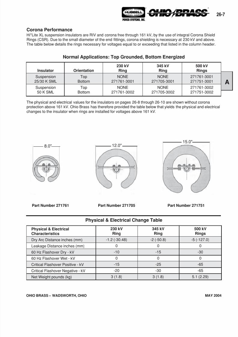
The physical and electrical values for the insulators on pages 26-8 through 26-10 are shown without coronaprotection above 161 kV. Ohio Brass has therefore provided the table below that yields the physical and electricalchanges to the insulator when rings are installed for voltages above 161 kV.
Corona PerformanceHi*Lite XL suspension insulators are RIV and corona free through 161 kV, by the use of integral Corona ShieldRings (CSR). Due to the small diameter of the end fittings, corona shielding is necessary at 230 kV and above.The table below details the rings necessary for voltages equal to or exceeding that listed in the column header.
Physical & Electrical Change Table
500 kV
Rings
-5 (-127.0)
0
-30
0
-65
-65
5.1 (2.29)
345 kV
Ring
-2 (-50.8)
0
-15
0
-25
-30
3 (1.8)
230 kV
Ring
-1.2 (-30.48)
0
-10
0
-15
-20
3 (1.8)
Physical & ElectricalCharacteristics
Dry Arc Distance inches (mm)
Leakage Distance inches (mm)
60 Hz Flashover Dry - kV
60 Hz Flashover Wet - kV
Critical Flashover Positive - kV
Critical Flashover Negative - kV
Net Weight pounds (kg)
Part Number 271761 Part Number 271705 Part Number 271751
15.0"12.0"8.0"
7/16/2019 OhioBrass - 26-HiLite Insulators
http://slidepdf.com/reader/full/ohiobrass-26-hilite-insulators 8/36
OHIO BRASS – WADSWORTH, OHIO
26-8
MAY 2004
® ®
POWER SYSTEMS, INC.
kg
-.11-.11-.01-.07
0-.007
Ground
Fitting
EyeEye
SocketClevis
Y-ClevisClevis
Line
Fitting
BallEyeBallBallEyeEye
Suffix
Code
100110001301140112001400
Inches
-.061.28-.97-1.001.34.34
mm
-1.532.5-24.6-25.434.08.6
Pounds
-2.5-2.5-.05-.15
0-.15
Weight ChangeLength Change
For configurations not shown contact Ohio Brass.
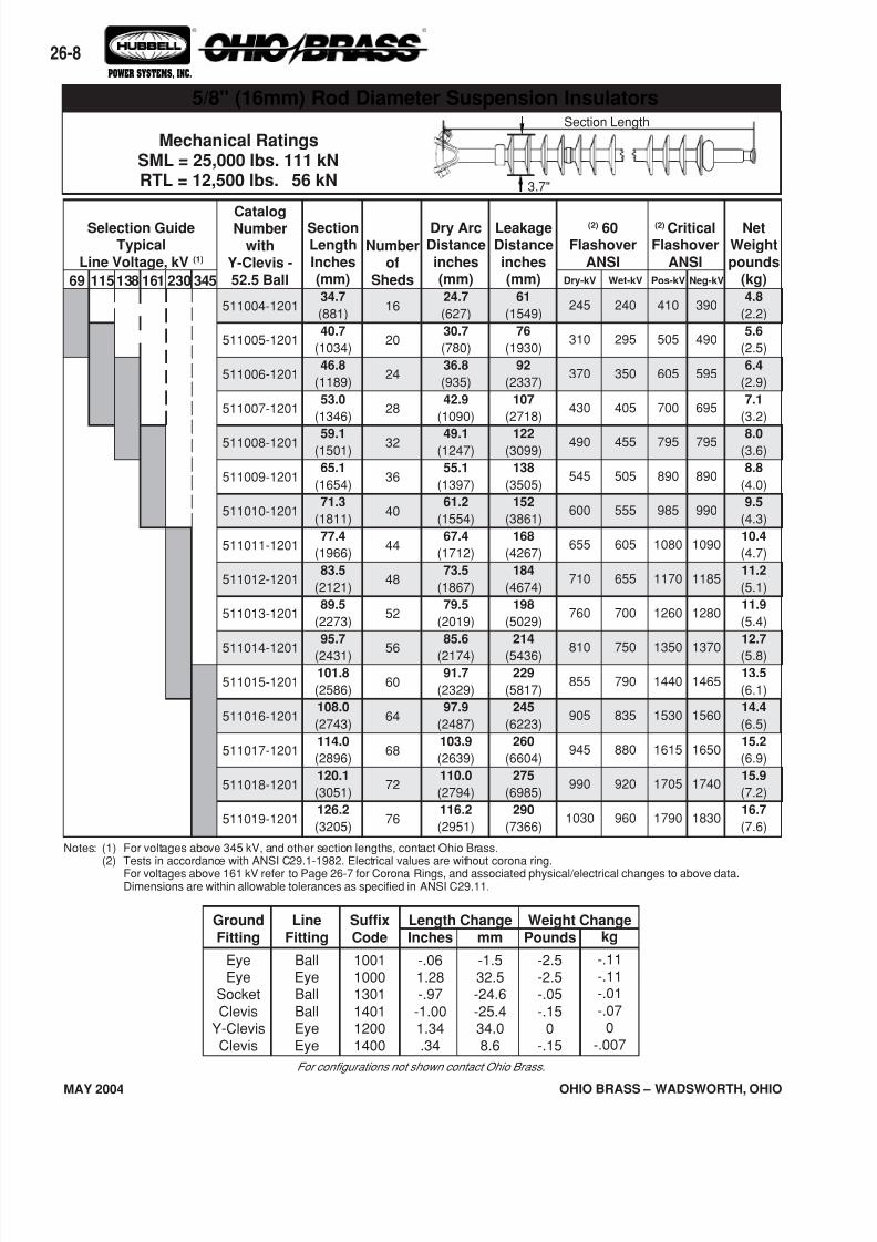
Mechanical RatingsSML = 25,000 lbs. 111 kNRTL = 12,500 lbs. 56 kN
NetWeight
pounds(kg)4.8
(2.2)
5.6
(2.5)
6.4
(2.9)
7.1
(3.2)
8.0(3.6)
8.8
(4.0)
9.5
(4.3)
10.4
(4.7)
11.2
(5.1)
11.9
(5.4)
12.7
(5.8)13.5
(6.1)
14.4
(6.5)
15.2
(6.9)
15.9
(7.2)
16.7
(7.6)
(2) CriticalFlashover
ANSI
CatalogNumber
withY-Clevis -
52.5 Ball
511004-1201
511005-1201
511006-1201
511007-1201
511008-1201
511009-1201
511010-1201
511011-1201
511012-1201
511013-1201
511014-1201
511015-1201
511016-1201
511017-1201
511018-1201
511019-1201
Neg-kV
390
490
595
695
795
890
990
1090
1185
1280
1370
1465
1560
1650
1740
1830
Pos-kV
410
505
605
700
795
890
985
1080
1170
1260
1350
1440
1530
1615
1705
1790
Wet-kV
240
295
350
405
455
505
555
605
655
700
750
790
835
880
920
960
Dry-kV
245
310
370
430
490
545
600
655
710
760
810
855
905
945
990
1030
(2) 60Flashover
ANSI
LeakageDistance
inches(mm)
61
(1549)
76
(1930)
92
(2337)
107
(2718)
122(3099)
138
(3505)
152
(3861)
168
(4267)
184
(4674)
198
(5029)
214
(5436)229
(5817)
245
(6223)
260
(6604)
275
(6985)
290
(7366)
Dry ArcDistance
inches(mm)24.7
(627)
30.7
(780)
36.8
(935)
42.9
(1090)
49.1(1247)
55.1
(1397)
61.2
(1554)
67.4
(1712)
73.5
(1867)
79.5
(2019)
85.6
(2174)91.7
(2329)
97.9
(2487)
103.9
(2639)
110.0
(2794)
116.2
(2951)
Numberof
Sheds
16
20
24
28
32
36
40
44
48
52
56
60
64
68
72
76
SectionLength
Inches(mm)34.7
(881)
40.7
(1034)
46.8
(1189)
53.0
(1346)
59.1(1501)
65.1
(1654)
71.3
(1811)
77.4
(1966)
83.5
(2121)
89.5
(2273)
95.7
(2431)101.8
(2586)
108.0
(2743)
114.0
(2896)
120.1
(3051)
126.2
(3205)
69 345230138 161115
Selection GuideTypical
Line Voltage, kV (1)
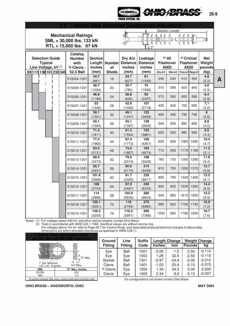
Notes: (1) For voltages above 345 kV, and other section lengths, contact Ohio Brass.(2) Tests in accordance with ANSI C29.1-1982. Electrical values are without corona ring.
For voltages above 161 kV refer to Page 26-7 for Corona Rings, and associated physical/electrical changes to above data.Dimensions are within allowable tolerances as specified in ANSI C29.11.
5/8" (16mm) Rod Diameter Suspension InsulatorsSection Length
3.7"
7/16/2019 OhioBrass - 26-HiLite Insulators
http://slidepdf.com/reader/full/ohiobrass-26-hilite-insulators 9/36
26-
OHIO BRASS – WADSWORTH, OHIO MAY 2004
® ®
POWER SYSTEMS, INC.
kg
-0.110-0.110-0.010-0.0700.000
-0.007
GroundFitting
EyeEye
SocketClevis
Y-ClevisClevis
LineFitting
BallEyeBallBallEyeEye
SuffixCode
100110001301140112001400
Inches
-0.061.28
-0.97-1.001.340.34
mm
-1.532.5
-24.6-25.434.08.6
Pounds
-2.50-2.50-0.05-0.150.00
-0.15
Weight ChangeLength Change
For configurations not shown contact Ohio Brass.
Y-Clevis Tower Attachment Detailfor 25k, 30k, and 50k SML Insulators
SML25/30k
50k
“D” Max. Inches.5311.0
To achieve insulator SML value, proper grade steel should be used
Mechanical RatingsSML = 30,000 lbs. 133 kNRTL = 15,000 lbs. 67 kN
NetWeightpounds
(kg)4.8
(2.2)
5.6
(2.5)
6.4
(2.9)
7.1
(3.2)
8
(3.6)
8.8
(4.0)
9.5
(4.3)
10.4
(4.7)
11.2
(5.1)
11.9
(5.4)
12.7
(5.8)13.5
(6.1)
14.4
(6.5)
15.2
(6.9)
15.9
(7.2)
16.7
(7.6)
(2) CriticalFlashover
ANSI
Catalog
Numberwith
Y-Clevis -52.5 Ball
515004-1201
515005-1201
515006-1201
515007-1201
515008-1201
515009-1201
515010-1201
515011-1201
515012-1201
515013-1201
515014-1201
515015-1201
515016-1201
515017-1201
515018-1201
515019-1201
Neg-kV
390
490
595
695
795
890
990
1090
1185
1280
1370
1465
1560
1650
1740
1830
Pos-kV
410
505
605
700
795
890
985
1080
1170
1260
1350
1440
1530
1615
1705
1790
Wet-kV
240
295
350
405
455
505
555
605
655
700
750
790
835
880
920
960
Dry-kV
245
310
370
430
490
545
600
655
710
760
810
855
905
945
990
1030
(2) 60Flashover
ANSI
LeakageDistanceinches(mm)
61
(1549)
76
(1930)
92
(2337)
107
(2718)
122
(3099)
138
(3505)
152
(3861)
168
(4267)
184
(4674)
198
(5029)
214
(5436)229
(5817)
245
(6223)
260
(6604)
275
(6985)
290
(7366)
Dry ArcDistanceinches(mm)24.7
(627)
30.7
(780)
36.8
(935)
42.9
(1090)
49.1
(1247)
55.1
(1397)
61.2
(1554)
67.4
(1712)
73.5
(1867)
79.5
(2019)
85.6
(2174)91.7
(2329)
97.9
(2487)
103.9
(2639)
110
(2794)
116.2
(2951)
Numberof
Sheds
16
20
24
28
32
36
40
44
48
52
56
60
64
68
72
76
SectionLengthInches(mm)34.7
(881)
40.7
(1034)
46.8
(1189)
53
(1346)
59.1
(1501)
65.1
(1654)
71.3
(1811)
77.4
(1966)
83.5
(2121)
89.5
(2273)
95.7
(2431)101.8
(2586)
108
(2743)
114
(2896)
120.1
(3051)
126.2
(3205)
69 345230138 161115
Selection GuideTypical
Line Voltage, kV (1)
Notes: (1) For voltages above 345 kV, and other section lengths, contact Ohio Brass.(2) Tests in accordance with ANSI C29.1-1982. Electrical values are without corona ring.
For voltages above 161 kV refer to Page 26-7 for Corona Rings, and associated physical/electrical changes to above data.Dimensions are within allowable tolerances as specified in ANSI C29.11.
Section Length
3.7"
5/8" (16mm) Rod Diameter Suspension Insulators
“D” Max.
3/4" Max.1" Dia. Minimum1/8" x 45° Chamfer
7/16/2019 OhioBrass - 26-HiLite Insulators
http://slidepdf.com/reader/full/ohiobrass-26-hilite-insulators 10/36
OHIO BRASS – WADSWORTH, OHIO
26-10
MAY 2004
® ®
POWER SYSTEMS, INC.
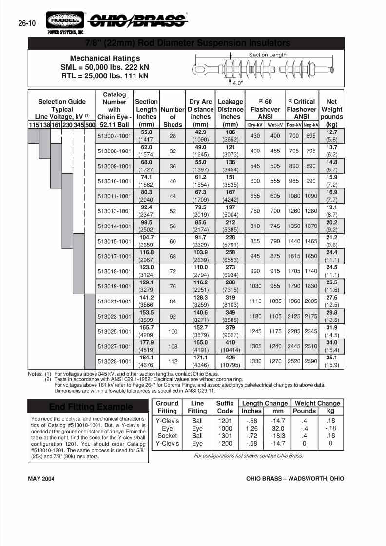
End Fitting Example
You need the electrical and mechanical characteris-
tics of Catalog #513010-1001. But, a Y-clevis is
needed at the ground end instead of an eye. From the
table at the right, find the code for the Y-clevis/ball
configuration 1201. You should order Catalog
#513010-1201. The same process is used for 5/8"
(25k) and 7/8" (30k) insulators.
kg
.18-.18.180
GroundFitting
Y-ClevisEye
SocketY-Clevis
LineFitting
BallEyeBallEye
SuffixCode
1201100013011200
Inches
-.581.26-.72-.58
mm
-14.732.0-18.3-14.7
Pounds
.4-.4.40
Weight ChangeLength Change
Mechanical RatingsSML = 50,000 lbs. 222 kNRTL = 25,000 lbs. 111 kN
For configurations not shown contact Ohio Brass.
7/8" (22mm) Rod Diameter Suspension Insulators
Net
Weightpounds
(kg)12.7
(5.8)
13.7
(6.2)
14.8
(6.7)
15.9
(7.2)
16.9(7.7)
19.1
(8.7)
20.2
(9.2)
21.2
(9.6)
24.4
(11.1)
24.5
(11.1)
25.5
(11.6)
27.6
(12.5)
29.8
(13.5)
31.9
(14.5)
34.0
(15.4)
35.1
(15.9)
(2) Critical
FlashoverANSI
CatalogNumber
with
Chain Eye -52.11 Ball
513007-1001
513008-1001
513009-1001
513010-1001
513011-1001
513013-1001
513014-1001
513015-1001
513017-1001
513018-1001
513019-1001
513021-1001
513023-1001
513025-1001
513027-1001
513028-1001
Neg-kV
695
795
890
990
1090
1280
1370
1465
1650
1740
1830
2005
2175
2345
2510
2590
Pos-kV
700
795
890
985
1080
1260
1350
1440
1615
1705
1790
1960
2125
2285
2445
2520
Wet-kV
400
455
505
555
605
700
745
790
875
915
955
1035
1105
1175
1240
1270
Dry-kV
430
490
545
600
655
760
810
855
945
990
1030
1110
1180
1245
1305
1330
(2) 60
FlashoverANSI
Leakage
Distanceinches
(mm)106
(2692)
121
(3073)
136
(3454)
151
(3835)
167(4242)
197
(5004)
212
(5385)
228
(5791)
258
(6553)
273
(6934)
288
(7315)
319
(8103)
349
(8885)
379
(9627)
410
(10414)
425
(10795)
Dry Arc
Distanceinches
(mm)42.9
(1090)
49.0
(1245)
55.0
(1397)
61.2
(1554)
67.3(1709)
79.5
(2019)
85.6
(2174)
91.7
(2329)
103.9
(2639)
110.0
(2794)
116.2
(2951)
128.3
(3259)
140.6
(3271)
152.7
(3879)
165.0
(4191)
171.1
(4346)
Number
ofSheds
28
32
36
40
44
52
56
60
68
72
76
84
92
100
108
112
Section
LengthInches
(mm)55.8
(1417)
62.0
(1574)
68.0
(1727)
74.1
(1882)
80.3(2040)
92.4
(2347)
98.5
(2502)
104.7
(2659)
116.8
(2967)
123.0
(3124)
129.1
(3279)
141.2
(3586)
153.5
(3899)
165.7
(4209)
177.9
(4519)
184.1
(4676)
115 500345161 230138
Selection Guide
TypicalLine Voltage, kV (1)
Notes: (1) For voltages above 345 kV, and other section lengths, contact Ohio Brass.(2) Tests in accordance with ANSI C29.1-1982. Electrical values are without corona ring.
For voltages above 161 kV refer to Page 26-7 for Corona Rings, and associated physical/electrical changes to above data.Dimensions are within allowable tolerances as specified in ANSI C29.11.
Section Length
4.0"
7/16/2019 OhioBrass - 26-HiLite Insulators
http://slidepdf.com/reader/full/ohiobrass-26-hilite-insulators 11/36
26-
OHIO BRASS – WADSWORTH, OHIO MAY 2004
® ®
POWER SYSTEMS, INC.
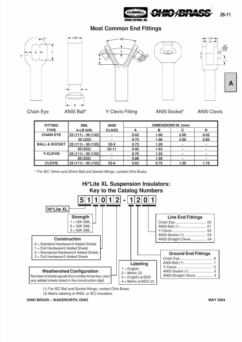
ANSI Clevis
SML
k-LB (kN)
25 (111) - 30 (133)
50 (222)
25 (111) - 30 (133)
50 (222)
25 (111) - 30 (133)
50 (222)
25 (111) - 30 (133)
ANSI
CLASS
-
-
52-5
52-11
-
-
52-6
A
0.62
0.75
0.73
0.92
0.75
0.88
0.62
D
0.62
0.85
-
-
-
-
1.10
C
2.00
2.00
-
-
-
-
1.50
B
1.00
1.00
1.29
1.63
1.53
1.59
0.75
FITTING
TYPE
CHAIN EYE
BALL & SOCKET
Y-CLEVIS
CLEVIS
DIMENSIONS IN. (mm)
5 1 1 1 1 10 02 2-
Line End FittingsChain Eye................................ 00ANSI Ball (1) ........................... 01Y-Clevis ................................... 02ANSI Socket (1) ...................... 03
ANSI Straight Clevis ............... 04
Ground End FittingsChain Eye.................................. 0ANSI Ball (1) ............................. 1Y-Clevis ..................................... 2ANSI Socket (1) ........................ 3ANSI Straight Clevis ................. 4
Labeling1 = English2 = Metric (2)3 = English w/SDD4 = Metric w/SDD (2)
Hi*Lite XL
Hi*Lite XL Suspension Insulators:Key to the Catalog Numbers
Strength1 = 25K SML5 = 30K SML3 = 50K SML
Construction0 = Standard Hardware/0 Added Sheds1 = Dull Hardware/0 Added Sheds2 = Standarad Hardware/2 Added Sheds3 = Dull Hardware/2 Added Sheds
Most Common End Fittings
* For IEC 16mm and 20mm Ball and Socket fittings, contact Ohio Brass.
Weathershed ConfigurationNumber of sheds equals this number times four, plusany added sheds listed in the construction digit.
ANSI Socket*Y-Clevis FittingANSI Ball*Chain Eye
(1) For IEC Ball and Socket fittings, contact Ohio Brass.
(2) Metric labeling of ANSI, or IEC insulators.
7/16/2019 OhioBrass - 26-HiLite Insulators
http://slidepdf.com/reader/full/ohiobrass-26-hilite-insulators 12/36
OHIO BRASS – WADSWORTH, OHIO
26-12
MAY 2004
® ®
POWER SYSTEMS, INC.
CatalogNumber
232032
232033
232034
232035
232036232083
232037
232072
232050
232038
232039
SectionLength
(X)
Numberof
Weather-Sheds
33
38
43
53
6369
72
88
91
102
111
in.
88.4
98.6
108.9
128.3
149.8162.1
168.2
201.0
207.1
229.7
248.1
(mm)
(2245)
(2504)
(2766)
(3259)
(3805)(4117)
(4272)
(5105)
(5260)
(5834)
(6302)
DryArcing
Distancein.
68.4
78.7
88.9
109.4
129.9142.2
148.3
181.1
187.2
209.7
228.2
(mm)
(1737)
(1999)
(2258)
(2779)
(3299)(3612)
(3767)
(4600)
(4755)
(5326)
(5796)
LeakageDistance
(mm)
(4978)
(5740)
(6477)
(7976)
(9474)(10389)
(10820)
(13233)
(13665)
(15316)
(16662)
in.
196
226
255
314
373409
426
521
538
603
656
(1) 60-HzFlashover
ANSI
Net
Weight
Dry-kV
665
750
835
985
11151190
1220
1370
1395
1465
1505
Wet-kV
605
680
755
890
10101015
1110
1250
1270
1340
1385
Neg-kV
1105
1265
1420
1730
20252200
2285
2720
2800
3080
3300
Pos-kV
1095
1250
1400
1695
19802145
2225
2645
2720
2990
3200
(1) ImpulseCritical
ANSI
lbs.
39.1
42.7
46.4
53.7
61.065.4
67.6
79.3
81.5
89.5
96.1
(kg)
(17.8)
(19.4)
(21.1)
(24.4)
(27.7)(29.7)
(30.7)
(36.0)
(37.0)
(40.6)
(43.6)
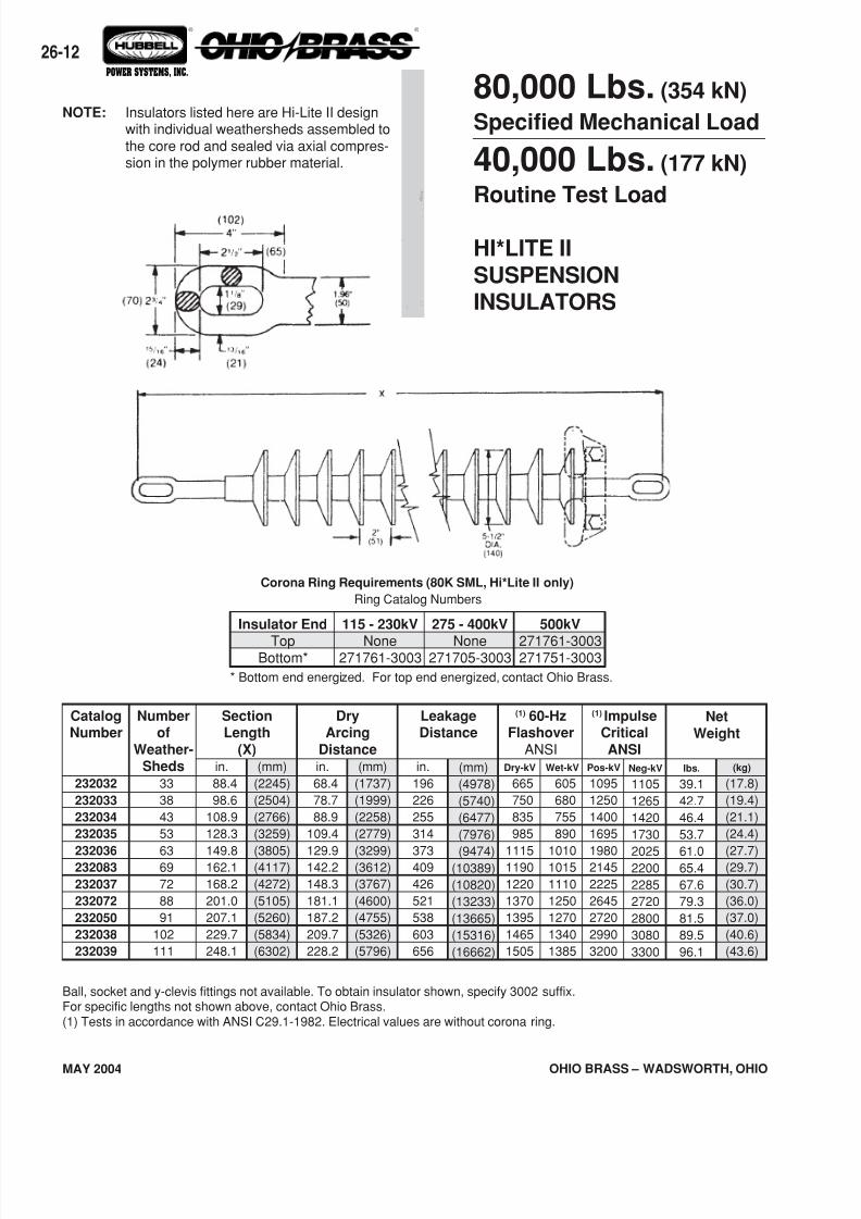
80,000 Lbs. (354 kN)
Specified Mechanical Load
40,000 Lbs. (177 kN)
Routine Test Load
HI*LITE IISUSPENSIONINSULATORS
Ball, socket and y-clevis fittings not available. To obtain insulator shown, specify 3002 suffix.For specific lengths not shown above, contact Ohio Brass.(1) Tests in accordance with ANSI C29.1-1982. Electrical values are without corona ring.
NOTE: Insulators listed here are Hi-Lite II designwith individual weathersheds assembled tothe core rod and sealed via axial compres-sion in the polymer rubber material.
Corona Ring Requirements (80K SML, Hi*Lite II only)
Ring Catalog Numbers
Insulator End
TopBottom*
115 - 230kV
None271761-3003
275 - 400kV
None271705-3003
500kV
271761-3003271751-3003
* Bottom end energized. For top end energized, contact Ohio Brass.
7/16/2019 OhioBrass - 26-HiLite Insulators
http://slidepdf.com/reader/full/ohiobrass-26-hilite-insulators 13/36
26-
OHIO BRASS – WADSWORTH, OHIO MAY 2004
® ®
POWER SYSTEMS, INC.
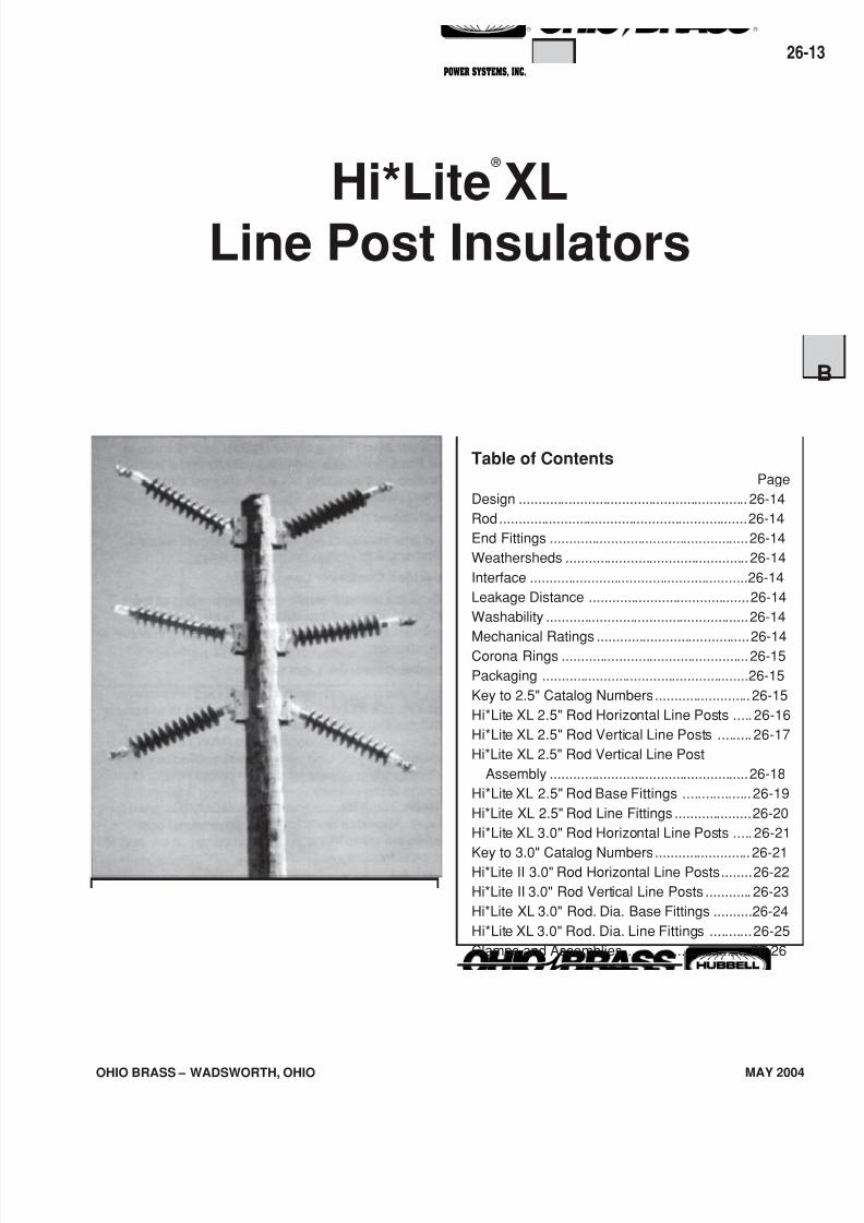
Hi*Lite ®
XL
Line Post Insulators
Table of ContentsPage
Design ............................................................ 26-14
Rod.................................................................26-14
End Fittings ....................................................26-14
Weathersheds ................................................ 26-14
Interface .........................................................26-14
Leakage Distance ..........................................26-14
Washability .....................................................26-14
Mechanical Ratings ........................................26-14Corona Rings .................................................26-15
Packaging ......................................................26-15
Key to 2.5" Catalog Numbers......................... 26-15
Hi*Lite XL 2.5" Rod Horizontal Line Posts ..... 26-16
Hi*Lite XL 2.5" Rod Vertical Line Posts ......... 26-17
Hi*Lite XL 2.5" Rod Vertical Line Post
Assembly ....................................................26-18
Hi*Lite XL 2.5" Rod Base Fittings ..................26-19
Hi*Lite XL 2.5" Rod Line Fittings ....................26-20
Hi*Lite XL 3.0" Rod Horizontal Line Posts ..... 26-21
Key to 3.0" Catalog Numbers......................... 26-21Hi*Lite II 3.0" Rod Horizontal Line Posts........26-22
Hi*Lite II 3.0" Rod Vertical Line Posts ............ 26-23
Hi*Lite XL 3.0" Rod. Dia. Base Fittings ..........26-24
Hi*Lite XL 3.0" Rod. Dia. Line Fittings ...........26-25
Clamps and Assemblies .................................26-26
7/16/2019 OhioBrass - 26-HiLite Insulators
http://slidepdf.com/reader/full/ohiobrass-26-hilite-insulators 14/36
OHIO BRASS – WADSWORTH, OHIO
26-14
MAY 2004
® ®
POWER SYSTEMS, INC.
Hi*Lite* ®
XL InsulatorsHi*Lite XL line post insulators in this publication em-body the latest features available in polymer insulatordesign and manufacture.
From the early prototypes in 1971, through full scaleintroduction in 1976, and through the succeedingyears, Hi*Lite insulators have featured conservativedesign and high-quality manufacture.
Today’s Hi*Lite insulators will add to the over1,000,000 already in service worldwide.
Design
The structural design of the Hi*Lite XL consists of thesebasic parts:
Rod - Hi*Lite insulator fiberglass rod is produced fromthe highest quality materials. Strands are aligned formaximum tensile strength. The rod is more than 50percent glass fibers in cross section.
End Fittings - End fittings are aluminum or ductile iron.They are crimped directly to the rod by a specialprocess originated by Ohio Brass, and later adopted bymany other producers. The crimp requires no inter-movement of the parts to achieve high strength, nordoes it introduce potting compounds or adhesives.
Weathersheds - Weathersheds are high pressureinjection molded by Ohio Brass, from the proprietarycompound ESP™. Housings manufactured with ESPsilicone alloy rubber exhibit hydrophobicity, highmechanical strength, high corona resistance and lowpermeability to moisture.
Interface - Hi*Lite insulators use Ohio Brass’ patentedlive silicone interface (U.S. Patent No. 3,898,372). Thisfeature prevents intrusion of moisture and contaminat-ing elements. If the exterior seal is damaged, redun-dant o-ring seals within the live silicone interfaceprohibit the lengthwise migration of intrusive elementsbetween shed and rod.
Leakage Distance
Hi*Lite XL insulators feature high leakage distance formaximum resistance to contamination and leakagecurrents.
Washability
Hi*Lite Line Post insulators listed in this catalog aresuitable for flood washing up to 200 psi. The designincorporates positive, labyrinth seals to ensure long-term security against water entry. Conventional dry-particle, air-pressure cleaning methods may also beemployed. A cleaning guideline is available from OhioBrass.
If your washing requirements exceed flood washing,contact Ohio Brass.
Mechanical Ratings
Line post insulators are basically cantilever supportmembers, with ratings defined as follows:
Specified Cantilever Load (SCL)
SCL is the ultimate cantilever strength rating of theHi*Lite XL line post insulator. SCL is identical to theminimum average breaking load (ABL) rating in previ-ous catalogs.
Routine Cantilever Load (RCL)
RCL is the maximum recommended load in cantileverthat a Hi*Lite XL post insulator is designed to withstandduring its life, and is equal to 50% of the SCL. RCL isidentical to maximum working load (MWL) listed inprevious catalogs. Line design loads applied to postinsulators often include tension, or compression, inaddition to the primary vertical cantilever load. Inaddition, some longitudinal load is usually designed foras well.
Combined Load
Contact your Hubbell Power Systems representativefor combined load applications.
7/16/2019 OhioBrass - 26-HiLite Insulators
http://slidepdf.com/reader/full/ohiobrass-26-hilite-insulators 15/36
26-
OHIO BRASS – WADSWORTH, OHIO MAY 2004
® ®
POWER SYSTEMS, INC.
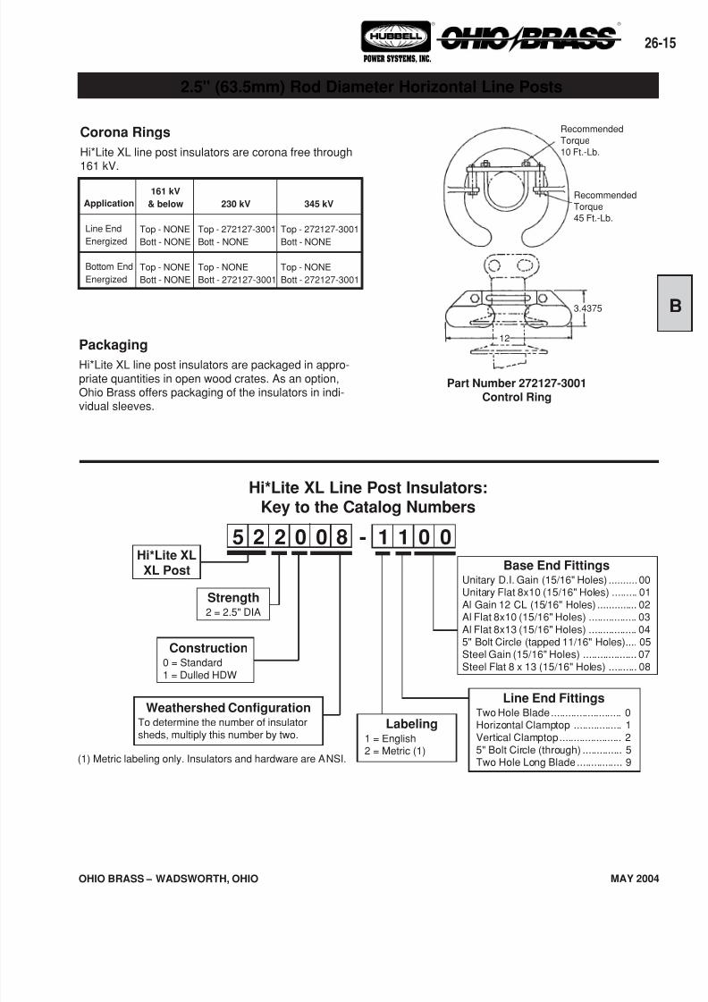
5 2 2 0 1 00 08 1-Hi*Lite XLXL Post
Strength2 = 2.5" DIA
Construction0 = Standard1 = Dulled HDW
Weathershed ConfigurationTo determine the number of insulatorsheds, multiply this number by two.
Hi*Lite XL Line Post Insulators:Key to the Catalog Numbers
Line End FittingsTwo Hole Blade......................... 0Horizontal Clamptop ................. 1Vertical Clamptop...................... 25" Bolt Circle (through) .............. 5Two Hole Long Blade................ 9
2.5" (63.5mm) Rod Diameter Horizontal Line Posts
Corona Rings
Hi*Lite XL line post insulators are corona free through161 kV.
PackagingHi*Lite XL line post insulators are packaged in appro-priate quantities in open wood crates. As an option,Ohio Brass offers packaging of the insulators in indi-vidual sleeves.
Part Number 272127-3001
Control Ring
Application
Line End
Energized
Bottom End
Energized
230 kV
Top - 272127-3001
Bott - NONE
Top - NONE
Bott - 272127-3001
161 kV
& below
Top - NONE
Bott - NONE
Top - NONE
Bott - NONE
345 kV
Top - 272127-3001
Bott - NONE
Top - NONE
Bott - 272127-3001
Base End FittingsUnitary D.I. Gain (15/16" Holes) .......... 00Unitary Flat 8x10 (15/16" Holes) ......... 01Al Gain 12 CL (15/16" Holes) .............. 02Al Flat 8x10 (15/16" Holes) ................. 03Al Flat 8x13 (15/16" Holes) ................. 045" Bolt Circle (tapped 11/16" Holes).... 05Steel Gain (15/16" Holes) ................... 07Steel Flat 8 x 13 (15/16" Holes) .......... 08
Recommended
Torque
10 Ft.-Lb.
Recommended
Torque
45 Ft.-Lb.
3.4375
12
(1) Metric labeling only. Insulators and hardware are ANSI.
Labeling1 = English2 = Metric (1)
7/16/2019 OhioBrass - 26-HiLite Insulators
http://slidepdf.com/reader/full/ohiobrass-26-hilite-insulators 16/36
OHIO BRASS – WADSWORTH, OHIO
26-16
MAY 2004
® ®
POWER SYSTEMS, INC.
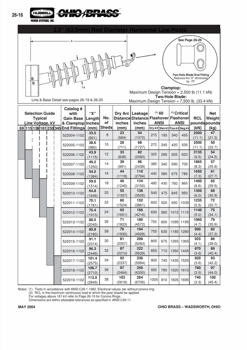
69 345230138 161115
Selection GuideTypical
Line Voltage, kV
Notes: (1) Tests in accordance with ANSI C29.1-1982. Electrical values are without corona ring.(2) RCL is the maximum continuous load at which the post should be applied.For voltages above 161 kV refer to Page 26-15 for Corona Rings.Dimensions are within allowable tolerances as specified in ANSI C29.11.
“X”
Length
Inches(mm)33.5
(851)
38.6
(980)
43.9
(1115)
49.2
(1250)
54.5
(1384)
59.6
(1514)
64.8
(1646)
70.1
(1781)
75.4
(1915)
80.5
(2045)
85.8
(2180)
91.1
(2314)96.3
(2446)
101.4
(2575)
106.7
(2710)
112.0
(2845)
Catalog #with
Gain Base
& ClamptopEnd Fittings
522004-1102
522005-1102
522006-1102
522007-1102
522008-1102
522009-1102
522010-1102
522011-1102
522012-1102
522013-1102
522014-1102
522015-1102
522016-1102
522017-1102
522018-1102
522019-1102
No.
ofSheds
8
10
12
14
16
18
20
22
24
26
28
30
32
34
36
38
Dry ArcDistance
inches(mm)
23
(584)
28
(711)
33
(838)
39
(991)
44
(1118)
49
(1245)
55
(1397)
60
(1524)
65
(1651)
71
(1803)
76
(1930)
81
(2057)87
(2210)
92
(2337)
97
(2464)
103
(2616)
LeakageDistance
inches(mm)
54
(1372)
68
(1727)
82
(2083)
96
(2438)
110
(2794)
124
(3150)
138
(3505)
152
(3861)
166
(4216)
180
(4572)
194
(4928)
208
(5283)222
(5639)
236
(5994)
250
(6350)
264
(6706)
(1) 60Flashover
ANSI
(1) CriticalFlashover
ANSI
NetWeight
pounds(kg)47
(21.3)
50
(22.7)
54
(24.5)
57
(25.9)
61
(27.7)
65
(29.5)
68
(30.9)
72
(32.7)
75
(34.1)
79
(35.9)
82
(37.2)
86
(39.0)89
(40.4)
93
(42.2)
97
(44.0)
100
(45.4)
RCL
pounds(kN)2500
(11.1)
2500
(11.1)
2135
(9.5)
1865
(8.3)
1650
(7.3)
1490
(6.6)
1350
(6.0)
1235
(5.5)
1140
(5.0)
1060
(4.7)
990
(4.4)
925
(4.1)870
(3.6)
820
(3.6)
780
(3.5)
740
(3.3)
Dry-kV
215
270
325
385
440
490
545
600
650
700
755
805
855
905
955
1005
Wet-kV
195
245
295
340
385
430
475
520
560
600
635
675
710
745
780
810
Pos-kV
340
420
505
590
675
760
845
930
1015
1095
1180
1265
1350
1435
1520
1605
Neg-kV
455
535
620
705
785
865
950
1035
1115
1195
1280
1365
1445
1525
1610
1695
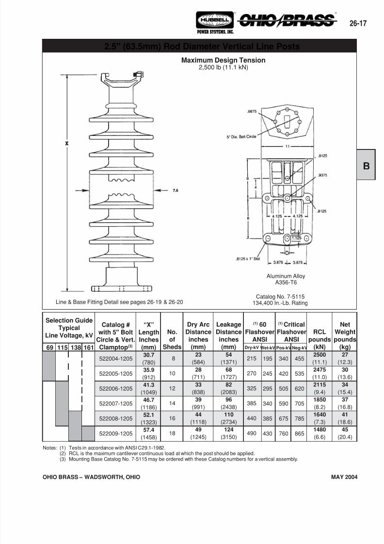
2.5" (63.5mm) Rod Diameter Horizontal Line Posts
Clamptop:Maximum Design Tension = 2,500 lb (11.1 kN)
Two-Hole Blade:Maximum Design Tension = 7,500 lb. (33.4 kN)
See Page 26-20
Two Hole Blade End FittingReduces the “X” dimension
by .75"
Line & Base Detail see pages 26-19 & 26-20
7/16/2019 OhioBrass - 26-HiLite Insulators
http://slidepdf.com/reader/full/ohiobrass-26-hilite-insulators 17/36
26-
OHIO BRASS – WADSWORTH, OHIO MAY 2004
® ®
POWER SYSTEMS, INC.
Line & Base Fitting Detail see pages 26-19 & 26-20
69
NetWeight
pounds(kg)27
(12.3)
30
(13.6)
34
(15.4)
37
(16.8)
41
(18.6)
45
(20.4)
Notes: (1) Tests in accordance with ANSI C29.1-1982.(2) RCL is the maximum cantilever continuous load at which the post should be applied.(3) Mounting Base Catalog No. 7-5115 may be ordered with these Catalog numbers for a vertical assembly.
115 138 161
Selection GuideTypical
Line Voltage, kV
Catalog #
with 5" BoltCircle & Vert.
Clamptop(3)
522004-1205
522005-1205
522006-1205
522007-1205
522008-1205
522009-1205
“X”
LengthInches
(mm)30.7
(780)
35.9
(912)
41.3
(1049)
46.7
(1186)
52.1
(1323)
57.4
(1458)
No.
ofSheds
8
10
12
14
16
18
Dry ArcDistance
inches(mm)
23
(584)
28
(711)
33
(838)
39
(991)
44
(1118)
49
(1245)
LeakageDistance
inches(mm)
54
(1371)
68
(1727)
82
(2083)
96
(2438)
110
(2734)
124
(3150)
(1) 60Flashover
ANSI
(1) CriticalFlashover
ANSIDry-kV
215
270
325
385
440
490
Wet-kV
195
245
295
340
385
430
Pos-kV
340
420
505
590
675
760
Neg-kV
455
535
620
705
785
865
RCL
pounds(kN)2500
(11.1)
2475
(11.0)
2115
(9.4)
1850
(8.2)
1640
(7.3)
1480
(6.6)
Maximum Design Tension2,500 lb (11.1 kN)
2.5" (63.5mm) Rod Diameter Vertical Line Posts
Aluminum AlloyA356-T6
Catalog No. 7-5115134,400 In.-Lb. Rating
7/16/2019 OhioBrass - 26-HiLite Insulators
http://slidepdf.com/reader/full/ohiobrass-26-hilite-insulators 18/36
OHIO BRASS – WADSWORTH, OHIO
26-18
MAY 2004
® ®
POWER SYSTEMS, INC.
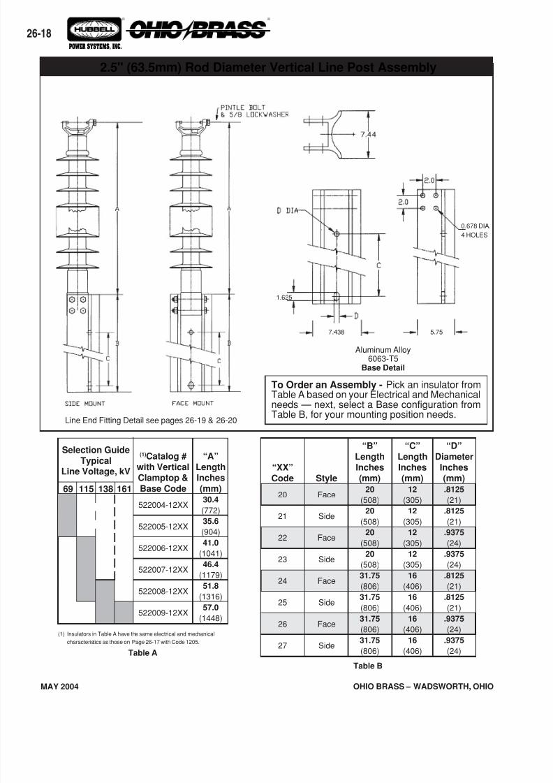
Line End Fitting Detail see pages 26-19 & 26-20
2.5" (63.5mm) Rod Diameter Vertical Line Post Assembly
Aluminum Alloy6063-T5
Base Detail
To Order an Assembly - Pick an insulator fromTable A based on your Electrical and Mechanicalneeds — next, select a Base configuration fromTable B, for your mounting position needs.
0.678 DIA.
4 HOLES
5.757.438
1.625
69
(1) Insulators in Table A have the same electrical and mechanical
characteristics as those on Page 26-17 with Code 1205.
Table A
115 138 161
Selection GuideTypical
Line Voltage, kV
(1)Catalog #
with VerticalClamptop &
Base Code
522004-12XX
522005-12XX
522006-12XX
522007-12XX
522008-12XX
522009-12XX
“A”
LengthInches
(mm)30.4
(772)
35.6
(904)
41.0
(1041)
46.4
(1179)
51.8
(1316)
57.0
(1448)
“XX”
Code
20
21
22
23
24
25
26
27
Style
Face
Side
Face
Side
Face
Side
Face
Side
“B”
LengthInches
(mm)20
(508)
20
(508)
20
(508)
20
(508)
31.75
(806)
31.75
(806)
31.75
(806)
31.75
(806)
“C”
LengthInches
(mm)12
(305)
12
(305)
12
(305)
12
(305)
16
(406)
16
(406)
16
(406)
16
(406)
“D”
DiameterInches
(mm).8125
(21)
.8125
(21)
.9375
(24)
.9375
(24)
.8125
(21)
.8125
(21)
.9375
(24)
.9375
(24)
Table B
7/16/2019 OhioBrass - 26-HiLite Insulators
http://slidepdf.com/reader/full/ohiobrass-26-hilite-insulators 19/36
26-
OHIO BRASS – WADSWORTH, OHIO MAY 2004
® ®
POWER SYSTEMS, INC.
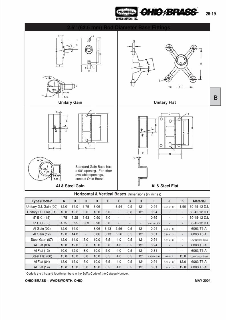
Al & Steel FlatAl & Steel Gain
Horizontal & Vertical Bases Dimensions (in inches)
Type (Code)*
Unitary D.I. Gain (00)
Unitary D.I. Flat (01)
5" B.C. (15)
5" B.C. (05)Al Gain (02)
Al Gain (12)
Steel Gain (07)
Al Flat (03)
Al Flat (13)
Steel Flat (08)
Al Flat (04)
Al Flat (14)
A
12.0
10.0
4.75
4.7512.0
12.0
12.0
10.0
10.0
13.0
13.0
13.0
B
14.0
12.2
6.25
6.2514.0
14.0
14.0
12.0
12.0
15.0
15.0
15.0
C
1.75
8.0
3.63
3.63-
-
8.0
8.0
8.0
8.0
8.0
8.0
E
-
5.0
5.0
5.06.13
6.13
6.5
5.0
5.0
6.5
6.5
6.5
F
3.54
-
-
-5.56
5.56
4.0
4.0
4.0
4.0
4.0
4.0
D
8.06
10.0
0.90
0.908.06
8.06
10.0
10.0
10.0
10.0
10.0
10.0
G
0.5
0.8
-
-0.5
0.5
0.5
0.5
0.5
0.5
0.5
0.5
H
12°
12°
-
-12°
12°
12°
12°
12°
12°
12°
12°
I
0.94
0.94
0.69
5/8 - 11 UFS
0.94
0.81
0.94
0.94
0.81
1.125 x 0.94
0.94
0.81
J
0.94 x 1.31
-
-
-0.94 x 1.31
0.94 x 1.31
0.94 x 1.31
-
-
0.94 x 2
0.94 x 1.31
0.81 x 1.31
K
1.90
-
-
--
-
-
-
-
12.0
12.0
12.0
Material
60-45-12 D.I.
60-45-12 D.I.
60-45-12 D.I.
60-45-12 D.I.6063 T5 Al
6063 T5 Al
Low Carbon Steel
6063 T5 Al
6063 T5 Al
Low Carbon Steel
6063 T5 Al
6063 T5 Al
*Code is the third and fourth numbers in the Suffix Code of the Catalog Number.
Unitary Gain Unitary Flat
2.5" (63.5 mm) Rod Diameter Base Fittings
Standard Gain Base hasa 90° opening. For otheravailable openings,contact Ohio Brass.
A
C
G
I
H
7/16/2019 OhioBrass - 26-HiLite Insulators
http://slidepdf.com/reader/full/ohiobrass-26-hilite-insulators 20/36
OHIO BRASS – WADSWORTH, OHIO
26-20
MAY 2004
® ®
POWER SYSTEMS, INC.
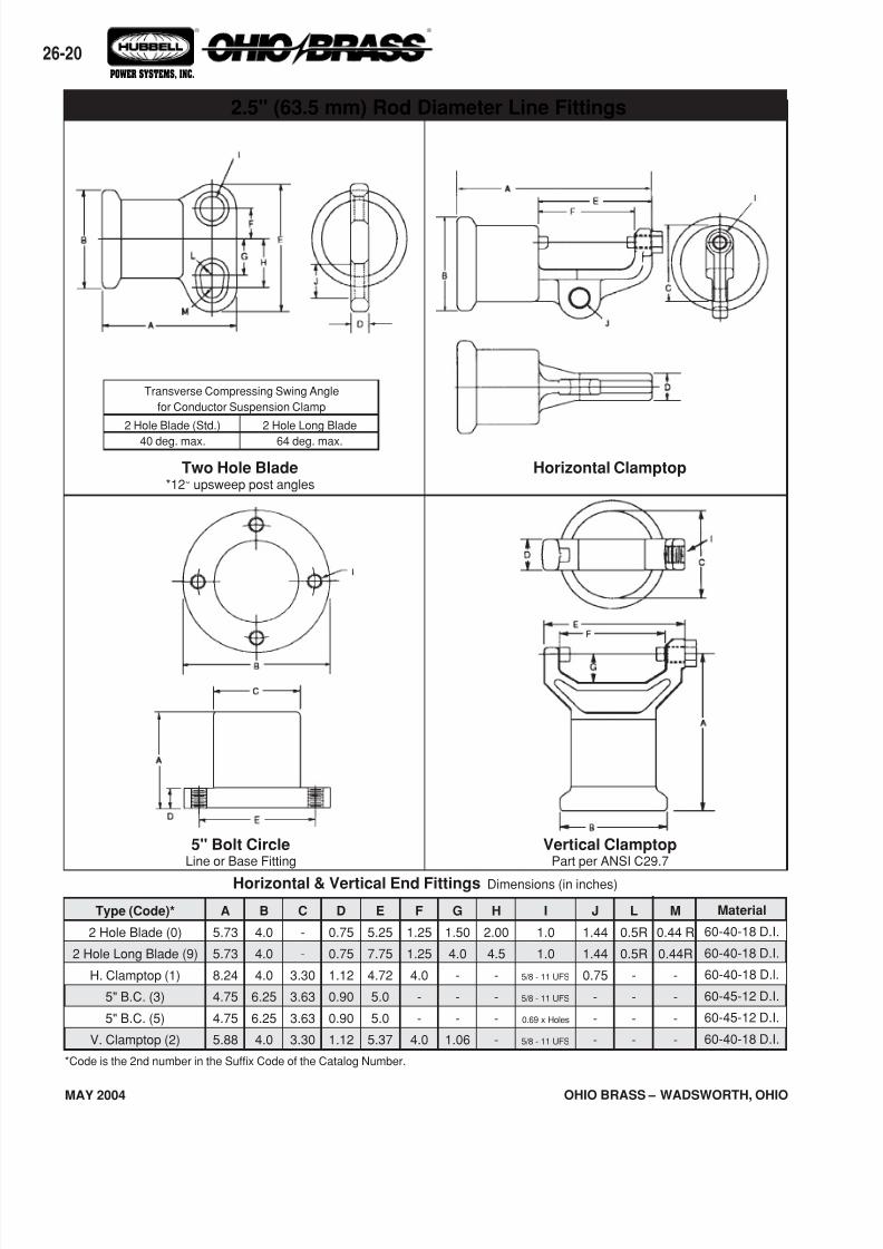
Two Hole Blade*12° upsweep post angles
Horizontal Clamptop
Vertical ClamptopPart per ANSI C29.7
5" Bolt CircleLine or Base Fitting
Horizontal & Vertical End Fittings Dimensions (in inches)
Material
60-40-18 D.I.
60-40-18 D.I.
60-40-18 D.l.
60-45-12 D.I.
60-45-12 D.I.
60-40-18 D.I.
Type (Code)*
2 Hole Blade (0)
2 Hole Long Blade (9)
H. Clamptop (1)
5" B.C. (3)
5" B.C. (5)
V. Clamptop (2)
L
0.5R
0.5R
-
-
-
-
M
0.44 R
0.44R
-
-
-
-
B
4.0
4.0
4.0
6.25
6.25
4.0
A
5.73
5.73
8.24
4.75
4.75
5.88
C
-
-
3.30
3.63
3.63
3.30
D
0.75
0.75
1.12
0.90
0.90
1.12
E
5.25
7.75
4.72
5.0
5.0
5.37
F
1.25
1.25
4.0
-
-
4.0
G
1.50
4.0
-
-
-
1.06
H
2.00
4.5
-
-
-
-
I
1.0
1.0
5/8 - 11 UFS
5/8 - 11 UFS
0.69 x Holes
5/8 - 11 UFS
J
1.44
1.44
0.75
-
-
-
*Code is the 2nd number in the Suffix Code of the Catalog Number.
2.5" (63.5 mm) Rod Diameter Line Fittings
2 Hole Long Blade
64 deg. max.
2 Hole Blade (Std.)
40 deg. max.
Transverse Compressing Swing Angle
for Conductor Suspension Clamp
7/16/2019 OhioBrass - 26-HiLite Insulators
http://slidepdf.com/reader/full/ohiobrass-26-hilite-insulators 21/36
26-
OHIO BRASS – WADSWORTH, OHIO MAY 2004
® ®
POWER SYSTEMS, INC.
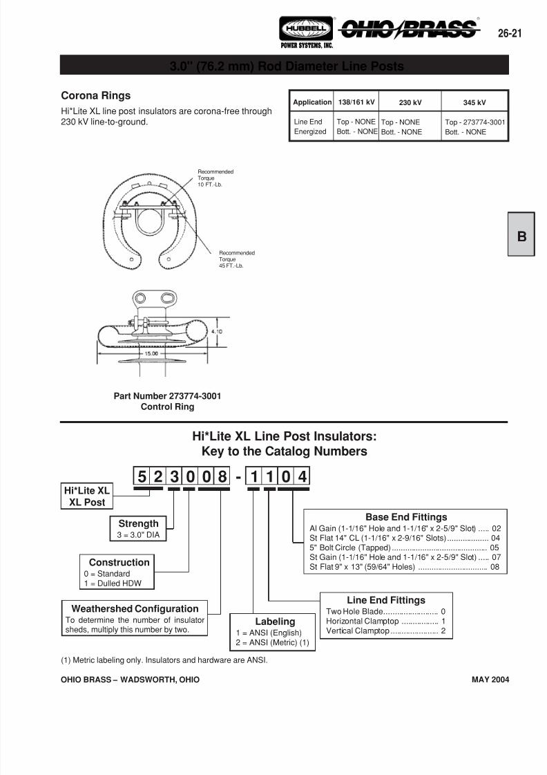
Application
Line End
Energized
230 kV
Top - NONE
Bott. - NONE
345 kV
Top - 273774-3001
Bott. - NONE
138/161 kV
Top - NONE
Bott. - NONE
Corona Rings
Hi*Lite XL line post insulators are corona-free through230 kV line-to-ground.
3.0" (76.2 mm) Rod Diameter Line Posts
RecommendedTorque45 FT.-Lb.
RecommendedTorque10 FT.-Lb.
Hi*Lite XL Line Post Insulators:Key to the Catalog Numbers
5 2 3 0 1 40 08 1-Hi*Lite XLXL Post
Strength3 = 3.0" DIA
Construction0 = Standard1 = Dulled HDW
Weathershed ConfigurationTo determine the number of insulatorsheds, multiply this number by two.
Line End FittingsTwo Hole Blade......................... 0Horizontal Clamptop ................. 1Vertical Clamptop...................... 2
Base End FittingsAl Gain (1-1/16" Hole and 1-1/16" x 2-5/9" Slot) ..... 02St Flat 14" CL (1-1/16" x 2-9/16" Slots)................... 045" Bolt Circle (Tapped) ............................................ 05St Gain (1-1/16" Hole and 1-1/16" x 2-5/9" Slot) ..... 07St Flat 9" x 13" (59/64" Holes) ................................ 08
Part Number 273774-3001
Control Ring
Labeling1 = ANSI (English)2 = ANSI (Metric) (1)
(1) Metric labeling only. Insulators and hardware are ANSI.
7/16/2019 OhioBrass - 26-HiLite Insulators
http://slidepdf.com/reader/full/ohiobrass-26-hilite-insulators 22/36
OHIO BRASS – WADSWORTH, OHIO
26-22
MAY 2004
® ®
POWER SYSTEMS, INC.
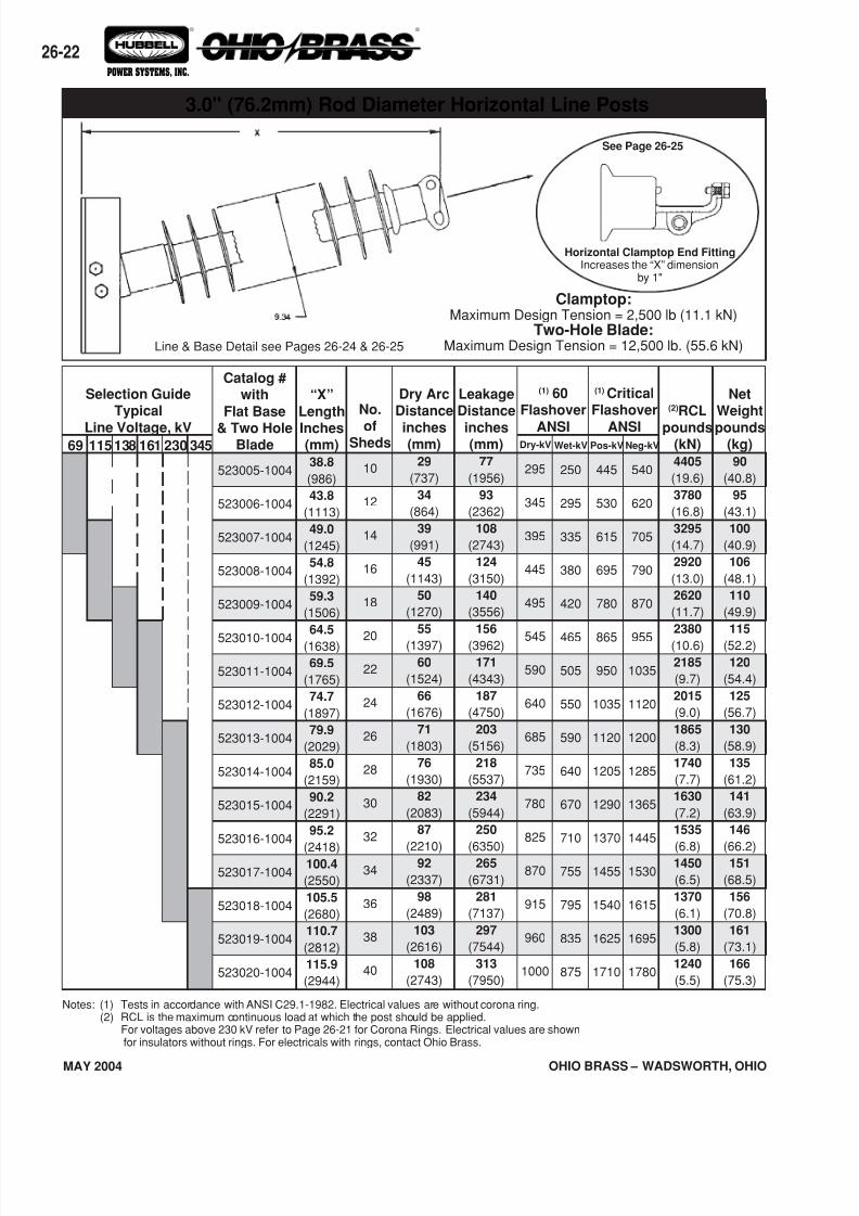
69 345230138 161115
Selection GuideTypical
Line Voltage, kV
Notes: (1) Tests in accordance with ANSI C29.1-1982. Electrical values are without corona ring.(2) RCL is the maximum continuous load at which the post should be applied.
For voltages above 230 kV refer to Page 26-21 for Corona Rings. Electrical values are shownfor insulators without rings. For electricals with rings, contact Ohio Brass.
“X”
Length
Inches(mm)38.8
(986)
43.8
(1113)
49.0
(1245)
54.8
(1392)
59.3
(1506)
64.5
(1638)
69.5
(1765)
74.7
(1897)
79.9
(2029)
85.0
(2159)
90.2
(2291)
95.2
(2418)100.4
(2550)
105.5
(2680)
110.7
(2812)
115.9
(2944)
Catalog #with
Flat Base
& Two HoleBlade
523005-1004
523006-1004
523007-1004
523008-1004
523009-1004
523010-1004
523011-1004
523012-1004
523013-1004
523014-1004
523015-1004
523016-1004
523017-1004
523018-1004
523019-1004
523020-1004
No.
ofSheds
10
12
14
16
18
20
22
24
26
28
30
32
34
36
38
40
Dry ArcDistance
inches(mm)
29
(737)
34
(864)
39
(991)
45
(1143)
50
(1270)
55
(1397)
60
(1524)
66
(1676)
71
(1803)
76
(1930)
82
(2083)
87
(2210)92
(2337)
98
(2489)
103
(2616)
108
(2743)
LeakageDistance
inches(mm)
77
(1956)
93
(2362)
108
(2743)
124
(3150)
140
(3556)
156
(3962)
171
(4343)
187
(4750)
203
(5156)
218
(5537)
234
(5944)
250
(6350)265
(6731)
281
(7137)
297
(7544)
313
(7950)
(1) 60Flashover
ANSI
(1) CriticalFlashover
ANSI
NetWeight
pounds(kg)90
(40.8)
95
(43.1)
100
(40.9)
106
(48.1)
110
(49.9)
115
(52.2)
120
(54.4)
125
(56.7)
130
(58.9)
135
(61.2)
141
(63.9)
146
(66.2)151
(68.5)
156
(70.8)
161
(73.1)
166
(75.3)
(2)RCL
pounds(kN)4405
(19.6)
3780
(16.8)
3295
(14.7)
2920
(13.0)
2620
(11.7)
2380
(10.6)
2185
(9.7)
2015
(9.0)
1865
(8.3)
1740
(7.7)
1630
(7.2)
1535
(6.8)1450
(6.5)
1370
(6.1)
1300
(5.8)
1240
(5.5)
Dry-kV
295
345
395
445
495
545
590
640
685
735
780
825
870
915
960
1000
Wet-kV
250
295
335
380
420
465
505
550
590
640
670
710
755
795
835
875
Pos-kV
445
530
615
695
780
865
950
1035
1120
1205
1290
1370
1455
1540
1625
1710
Neg-kV
540
620
705
790
870
955
1035
1120
1200
1285
1365
1445
1530
1615
1695
1780
3.0" (76.2mm) Rod Diameter Horizontal Line Posts
See Page 26-25
Line & Base Detail see Pages 26-24 & 26-25
Clamptop:Maximum Design Tension = 2,500 lb (11.1 kN)
Two-Hole Blade:Maximum Design Tension = 12,500 lb. (55.6 kN)
Horizontal Clamptop End FittingIncreases the “X” dimension
by 1"
7/16/2019 OhioBrass - 26-HiLite Insulators
http://slidepdf.com/reader/full/ohiobrass-26-hilite-insulators 23/36
26-
OHIO BRASS – WADSWORTH, OHIO MAY 2004
® ®
POWER SYSTEMS, INC.
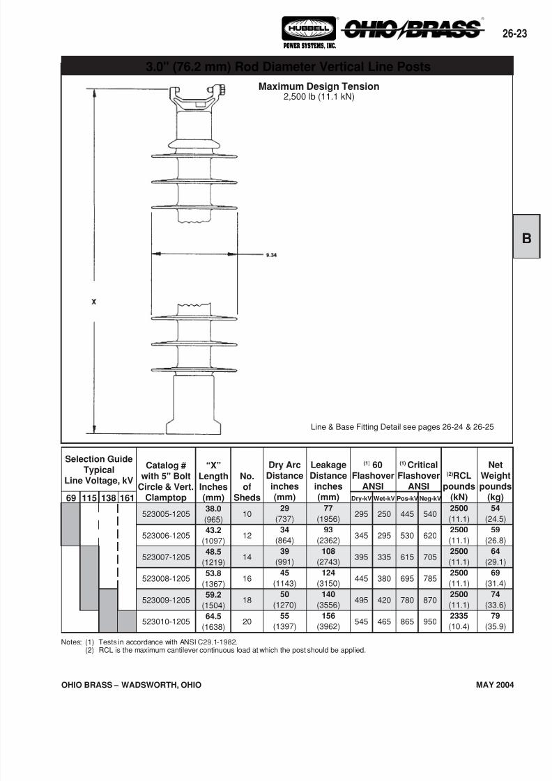
69
Net
Weightpounds
(kg)54
(24.5)
59
(26.8)
64
(29.1)
69
(31.4)
74
(33.6)
79
(35.9)
Notes: (1) Tests in accordance with ANSI C29.1-1982.(2) RCL is the maximum cantilever continuous load at which the post should be applied.
115 138 161
Selection Guide
TypicalLine Voltage, kV
Catalog #
with 5" BoltCircle & Vert.
Clamptop
523005-1205
523006-1205
523007-1205
523008-1205
523009-1205
523010-1205
“X”
LengthInches(mm)38.0
(965)
43.2
(1097)
48.5
(1219)
53.8
(1367)
59.2
(1504)
64.5
(1638)
Dry Arc
Distanceinches(mm)
29
(737)
34
(864)
39
(991)
45
(1143)
50
(1270)
55
(1397)
Leakage
Distanceinches(mm)
77
(1956)
93
(2362)
108
(2743)
124
(3150)
140
(3556)
156
(3962)
(1) 60
FlashoverANSI
(1) Critical
FlashoverANSI
Wet-kV
250
295
335
380
420
465
Pos-kV
445
530
615
695
780
865
Neg-kV
540
620
705
785
870
950
(2)RCLpounds
(kN)2500
(11.1)
2500
(11.1)
2500
(11.1)
2500
(11.1)
2500
(11.1)
2335
(10.4)
No.of
Sheds
10
12
14
16
18
20
Dry-kV
295
345
395
445
495
545
Line & Base Fitting Detail see pages 26-24 & 26-25
Maximum Design Tension2,500 lb (11.1 kN)
3.0" (76.2 mm) Rod Diameter Vertical Line Posts
7/16/2019 OhioBrass - 26-HiLite Insulators
http://slidepdf.com/reader/full/ohiobrass-26-hilite-insulators 24/36
OHIO BRASS – WADSWORTH, OHIO
26-24
MAY 2004
® ®
POWER SYSTEMS, INC.
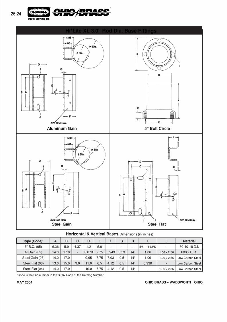
Horizontal & Vertical Bases Dimensions (in inches)
Type (Code)*
5" B.C. (05)
Al Gain (02)
Steel Gain (07)
Steel Flat (08)
Steel Flat (04)
A
6.36
14.0
14.0
13.0
14.0
B
5.9
17.0
17.0
15.0
17.0
C
4.37
-
-
9.0
-
E
5.0
7.75
7.75
6.5
7.75
F
-
5.949
7.03
4.12
4.12
D
1.2
8.079
9.65
11.0
10.0
G
-
0.53
0.5
0.5
0.5
H
-
14°
14°
14°
14°
I
5/8 - 11 UFS
1.06
1.06
0.938
-
J
-
1.06 x 2.56
1.06 x 2.56
-
1.06 x 2.56
Material
60-40-18 D.I.
6063 T5 Al
Low Carbon Steel
Low Carbon Steel
Low Carbon Steel
*Code is the 2nd number in the Suffix Code of the Catalog Number.
Steel FlatSteel Gain
Hi*Lite XL 3.0" Rod Dia. Base Fittings
Aluminum Gain 5" Bolt Circle
7/16/2019 OhioBrass - 26-HiLite Insulators
http://slidepdf.com/reader/full/ohiobrass-26-hilite-insulators 25/36
26-
OHIO BRASS – WADSWORTH, OHIO MAY 2004
® ®
POWER SYSTEMS, INC.
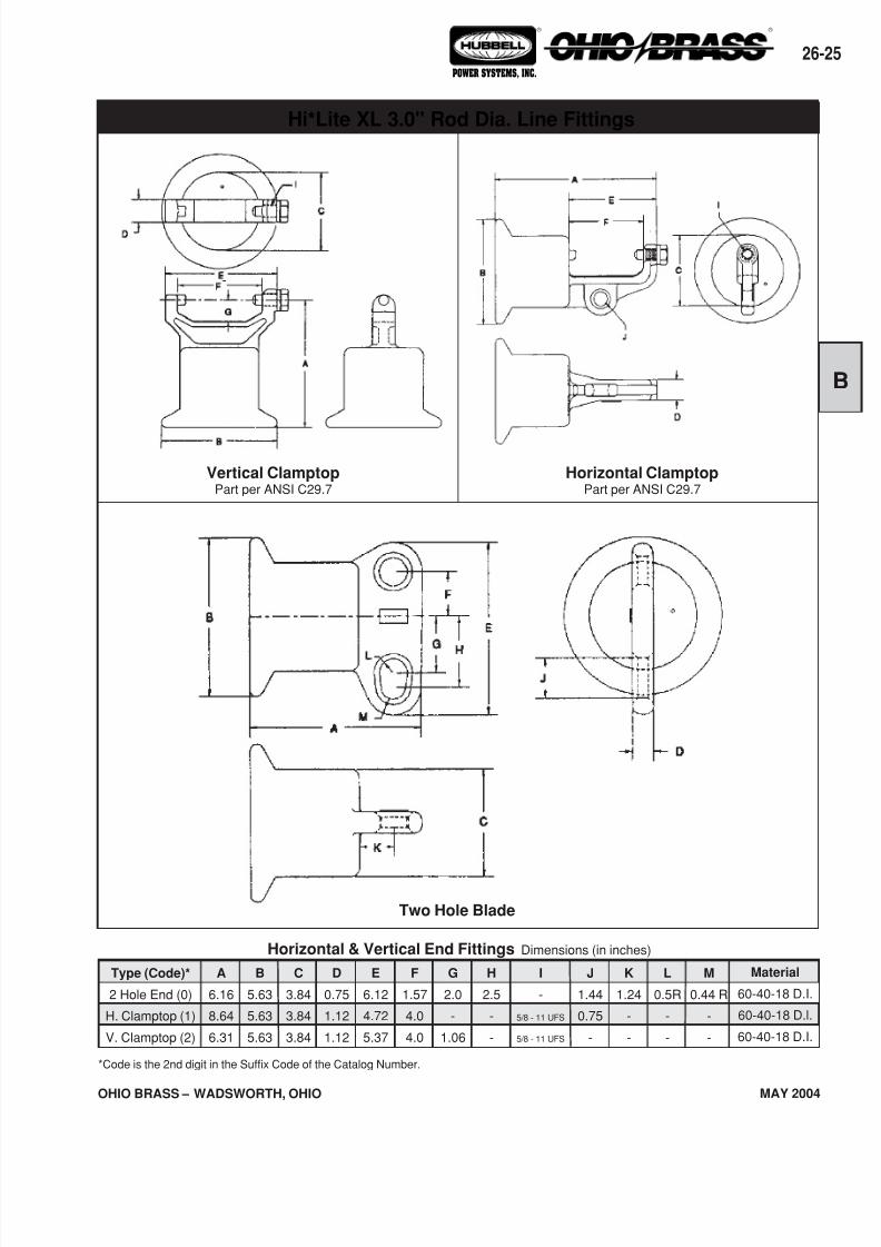
*Code is the 2nd digit in the Suffix Code of the Catalog Number.
Vertical ClamptopPart per ANSI C29.7
Horizontal ClamptopPart per ANSI C29.7
Material
60-40-18 D.I.
60-40-18 D.l.
60-40-18 D.I.
B
5.63
5.63
5.63
A
6.16
8.64
6.31
Type (Code)*
2 Hole End (0)
H. Clamptop (1)
V. Clamptop (2)
C
3.84
3.84
3.84
D
0.75
1.12
1.12
E
6.12
4.72
5.37
F
1.57
4.0
4.0
G
2.0
-
1.06
H
2.5
-
-
I
-
5/8 - 11 UFS
5/8 - 11 UFS
J
1.44
0.75
-
K
1.24
-
-
L
0.5R
-
-
M
0.44 R
-
-
Horizontal & Vertical End Fittings Dimensions (in inches)
Two Hole Blade
Hi*Lite XL 3.0" Rod Dia. Line Fittings
7/16/2019 OhioBrass - 26-HiLite Insulators
http://slidepdf.com/reader/full/ohiobrass-26-hilite-insulators 26/36
OHIO BRASS – WADSWORTH, OHIO
26-26
MAY 2004
® ®
POWER SYSTEMS, INC.
Figure 2 Figure 4
Figure 1 Figure 3
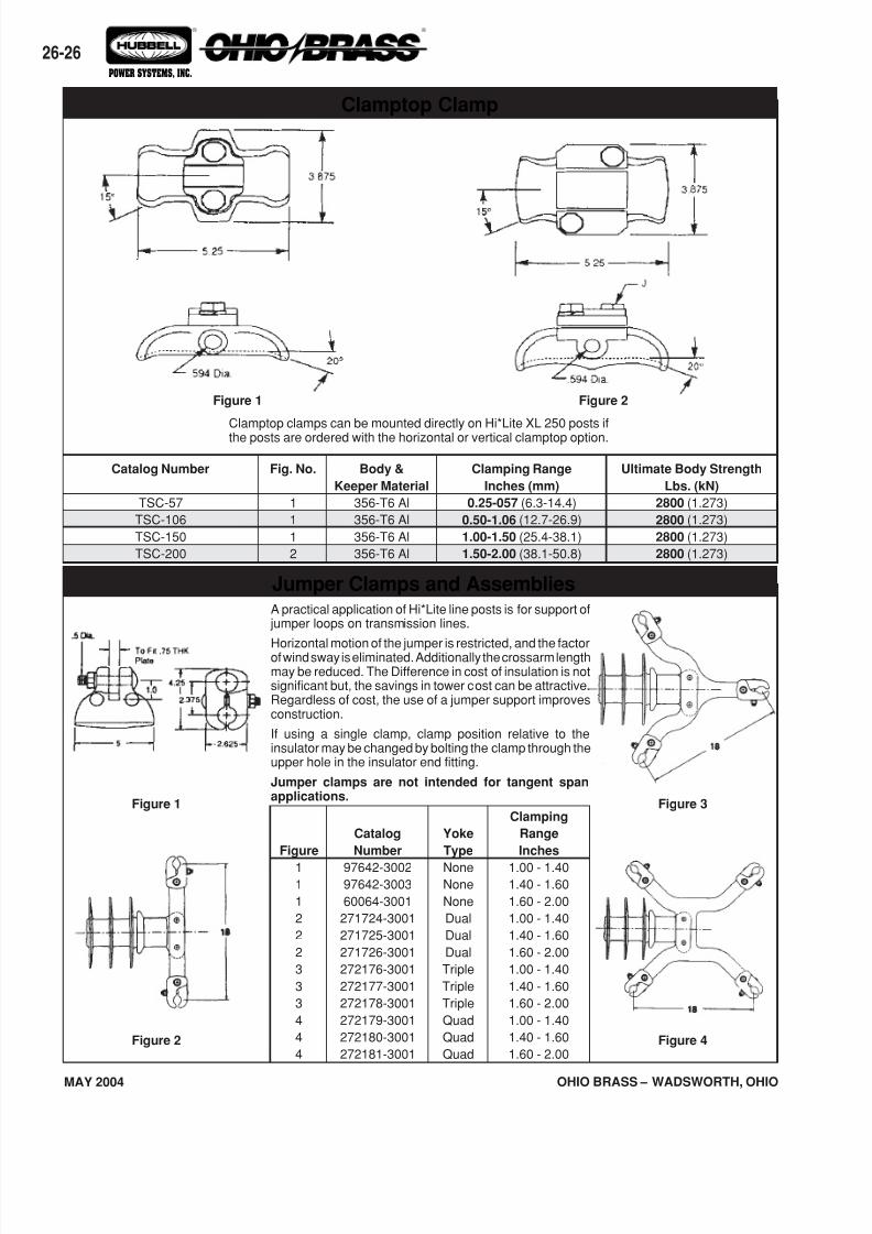
Clamptop Clamp
Jumper Clamps and Assemblies
Yoke
Type
NoneNone
None
Dual
Dual
Dual
Triple
Triple
Triple
Quad
Quad
Quad
Clamping
Range
Inches
1.00 - 1.401.40 - 1.60
1.60 - 2.00
1.00 - 1.40
1.40 - 1.60
1.60 - 2.00
1.00 - 1.40
1.40 - 1.60
1.60 - 2.00
1.00 - 1.40
1.40 - 1.60
1.60 - 2.00
Figure
11
1
2
2
2
3
3
3
4
4
4
Catalog
Number
97642-300297642-3003
60064-3001
271724-3001
271725-3001
271726-3001
272176-3001
272177-3001
272178-3001
272179-3001
272180-3001
272181-3001
A practical application of Hi*Lite line posts is for support of jumper loops on transmission lines.
Horizontal motion of the jumper is restricted, and the factorof wind sway is eliminated. Additionally the crossarm lengthmay be reduced. The Difference in cost of insulation is notsignificant but, the savings in tower cost can be attractive.Regardless of cost, the use of a jumper support improvesconstruction.
If using a single clamp, clamp position relative to theinsulator may be changed by bolting the clamp through theupper hole in the insulator end fitting.
Jumper clamps are not intended for tangent spanapplications.
Catalog Number
TSC-57
TSC-106
TSC-150
TSC-200
Fig. No.
1
1
1
2
Body &
Keeper Material
356-T6 Al
356-T6 Al
356-T6 Al
356-T6 Al
Ultimate Body Strength
Lbs. (kN)
2800 (1.273)
2800 (1.273)
2800 (1.273)
2800 (1.273)
Clamping Range
Inches (mm)
0.25-057 (6.3-14.4)
0.50-1.06 (12.7-26.9)
1.00-1.50 (25.4-38.1)
1.50-2.00 (38.1-50.8)
Clamptop clamps can be mounted directly on Hi*Lite XL 250 posts ifthe posts are ordered with the horizontal or vertical clamptop option.
Figure 1 Figure 2
7/16/2019 OhioBrass - 26-HiLite Insulators
http://slidepdf.com/reader/full/ohiobrass-26-hilite-insulators 27/36
26-
OHIO BRASS – WADSWORTH, OHIO MAY 2004
® ®
POWER SYSTEMS, INC.
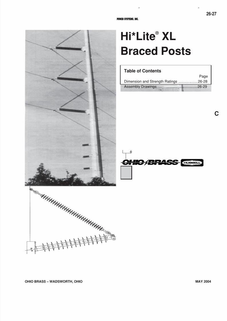
Hi*Lite ®
XL
Braced PostsTable of Contents
Page
Dimension and Strength Ratings ...................26-28
Assembly Drawings........................................26-29
7/16/2019 OhioBrass - 26-HiLite Insulators
http://slidepdf.com/reader/full/ohiobrass-26-hilite-insulators 28/36
OHIO BRASS – WADSWORTH, OHIO
26-28
MAY 2004
® ®
POWER SYSTEMS, INC.
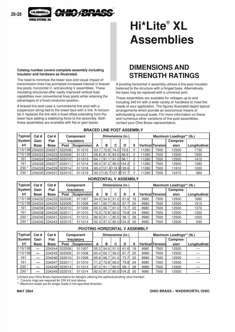
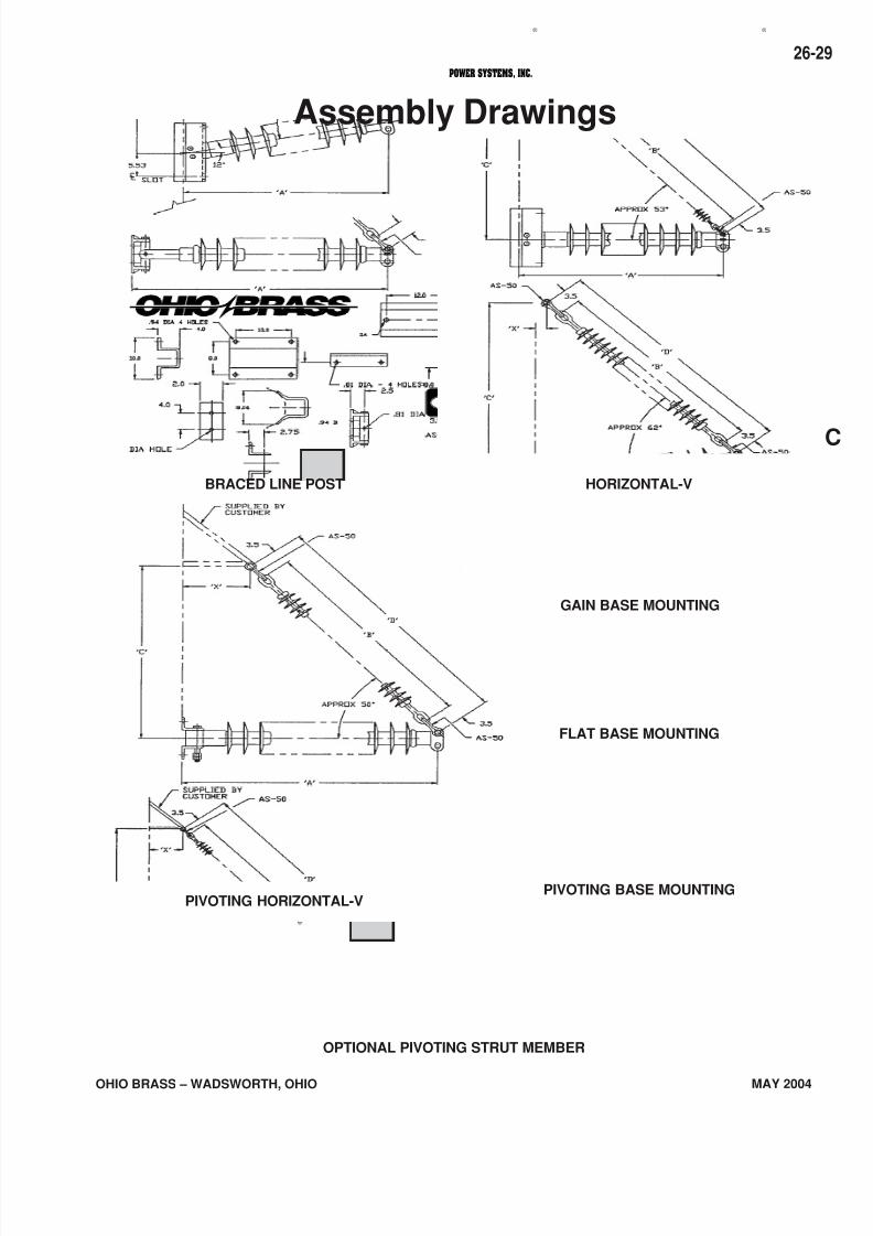
Catalog number covers complete assembly includinginsulator and hardware as illustrated.
The need to minimize the tower size and visual impact oftransmission lines has prompted increased interest in bracedline posts, horizontal-V, and pivoting V assemblies. Theseinsulating structures offer vastly improved vertical loadcapabilities over conventional lines posts while retaining theadvantages of a fixed conductor position.
A braced line post uses a conventional line post with asuspension string tied to the tower face with a link. A horizon-tal-V replaces the link with a fixed offset extending from thetower face adding a stabilizing force to the assembly. Boththese assemblies are available with flat or gain bases.
A pivoting horizontal-V assembly utilizes a line post insulatorfastened to the structure with a hinged base. Alternatively,the base may be replaced with a universal joint.
These assemblies are available for voltages up to andincluding 345 kV with a wide variety of hardware to meet theneeds of your application. The figures illustrated depict typicalarrangements which provide an economical means of
withstanding unusual loads. For more information on theseand numerous other variations of line post assemblies,contact your Ohio Brass representative.
DIMENSIONS ANDSTRENGTH RATINGS
Suspension
511010
511211
511013
511014
511018
511219
BRACED LINE POST ASSEMBLY
Typical
System
kV
115/138
115/138
161
161
230 *
230 *
Cat #
Gain
Base
234220
234222
234224
234226
234228
234230
Cat #
Flat
Base
234221
234223
234225
234227
234229
234231
Post
522008
522009
522010
522011
522014
522015
Component
Insulators
Vertical
11280
11280
11280
11280
11280
11280
Tension
7500
7500
7500
7500
7500
7500
Longitudinal
1730
1550
1410
1280
1020
960
Dimensions (in.) Maximum Loadings** (lb.)
A
53.7
58.8
64.1
69.4
85.0
90.3
B
72.8
81.9
91.1
97.2
121.6
130.7
C
74.0
83.0
91.0
96.0
118.0
127.0
X
2
2
2
2
2
2
D
79.8
88.9
98.1
104.2
128.6
137.7
Compres-
sion
12500
12500
12500
12500
11810
10470
Suspension
511007
511008
511009
511010
511013
511014
HORIZONTAL V ASSEMBLY
Typical
System
kV
115/138
115/138
161
161
230 *
230 *
Cat #
Gain
Base
234232
234234
234236
234238
234240
234242
Cat #
Flat
Base
234233
234235
234237
234239
234241
234243
Post
522008
522009
522010
522011
522014
522015
Component
Insulators
Vertical
9980
9980
9980
9980
9980
9980
Tension
7500
7500
7500
7500
7500
7500
Longitudinal
1680
1510
1370
1250
1000
930
Dimensions (in.) Maximum Loadings** (lb.)
A
54.9
60.1
65.5
70.9
86.9
92.3
B
54.6
60.7
66.7
72.8
91.1
97.2
C
51.0
56.0
61.0
66.0
80.0
85.0
X
18
20
22
24
28
30
D
61.6
67.7
73.7
79.8
98.1
104.2
Compres-
sion
12500
12500
12500
12500
12500
12500
Suspension
511007
511008
511009
511010
511013
511014
PIVOTING HORIZONTAL V ASSEMBLY
Typical
System
kV
115/138
115/138
161
161
230 *
230 *
Cat #
Gain
Base
—
—
—
—
—
—
Cat #
Flat
Base
234244
234245
234246
234247
234248
234249
Post
522008
522009
522010
522011
522014
522015
Component
Insulators
Vertical
9980
9980
9980
9980
9980
9980
Tension
7500
7500
7500
7500
7500
7500
Longitudinal
—
—
—
—
—
—
Dimensions (in.) Maximum Loadings** (lb.)
A
55.2
60.4
65.8
71.2
87.2
92.6
B
54.6
60.7
66.7
72.8
91.1
97.2
C
51.0
56.0
61.0
66.0
80.0
85.0
X
18
20
22
24
28
30
D
61.6
67.7
73.7
79.8
98.1
104.2
Compres-
sion
12500
12500
12500
12500
12500
12500
Contact your Ohio Brass representative for designs utilizing the optional pivoting strut member.* Corona rings are required for 230 kV and above.** Maximum loads are for single loads in the specified direction.
Hi*Lite ®
XLAssemblies
7/16/2019 OhioBrass - 26-HiLite Insulators
http://slidepdf.com/reader/full/ohiobrass-26-hilite-insulators 29/36
26-
OHIO BRASS – WADSWORTH, OHIO MAY 2004
® ®
POWER SYSTEMS, INC.
OPTIONAL PIVOTING STRUT MEMBER
FLAT BASE MOUNTING
PIVOTING BASE MOUNTINGPIVOTING HORIZONTAL-V
BRACED LINE POST HORIZONTAL-V
GAIN BASE MOUNTING
Assembly Drawings
7/16/2019 OhioBrass - 26-HiLite Insulators
http://slidepdf.com/reader/full/ohiobrass-26-hilite-insulators 30/36
OHIO BRASS – WADSWORTH, OHIO
26-30
MAY 2004
® ®
POWER SYSTEMS, INC.
7/16/2019 OhioBrass - 26-HiLite Insulators
http://slidepdf.com/reader/full/ohiobrass-26-hilite-insulators 31/36
26-
OHIO BRASS – WADSWORTH, OHIO MAY 2004
® ®
POWER SYSTEMS, INC.
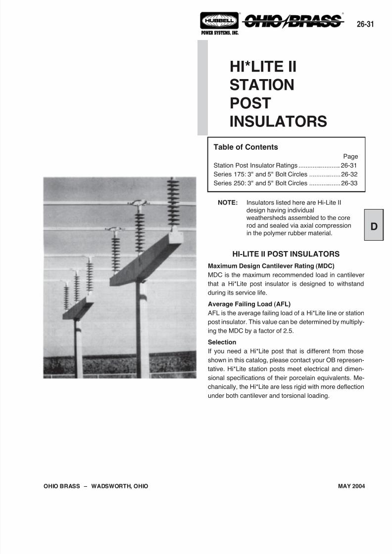
HI-LITE II POST INSULATORS
Maximum Design Cantilever Rating (MDC)
MDC is the maximum recommended load in cantilever
that a Hi*Lite post insulator is designed to withstand
during its service life.
Average Failing Load (AFL)
AFL is the average failing load of a Hi*Lite line or station
post insulator. This value can be determined by multiply-
ing the MDC by a factor of 2.5.
Selection
If you need a Hi*Lite post that is different from those
shown in this catalog, please contact your OB represen-
tative. Hi*Lite station posts meet electrical and dimen-
sional specifications of their porcelain equivalents. Me-
chanically, the Hi*Lite are less rigid with more deflectionunder both cantilever and torsional loading.
HI*LITE IISTATION
POSTINSULATORS
Table of ContentsPage
Station Post Insulator Ratings ........................ 26-31
Series 175: 3" and 5" Bolt Circles ..................26-32
Series 250: 3" and 5" Bolt Circles ..................26-33
NOTE: Insulators listed here are Hi-Lite II
design having individualweathersheds assembled to the core
rod and sealed via axial compressionin the polymer rubber material.
7/16/2019 OhioBrass - 26-HiLite Insulators
http://slidepdf.com/reader/full/ohiobrass-26-hilite-insulators 32/36
OHIO BRASS – WADSWORTH, OHIO
26-32
MAY 2004
® ®
POWER SYSTEMS, INC.
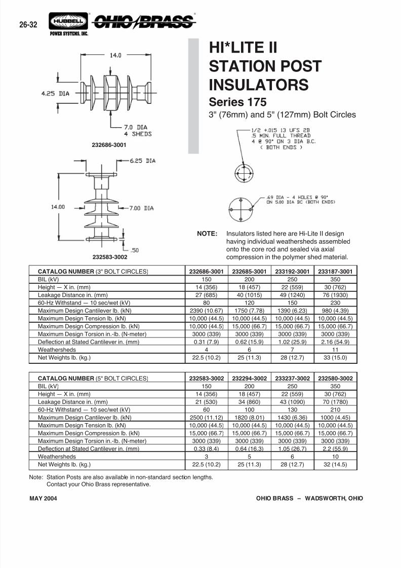
Note: Station Posts are also available in non-standard section lengths.
Contact your Ohio Brass representative.
CATALOG NUMBER (3" BOLT CIRCLES)
BIL (kV)
Height — X in. (mm)
Leakage Distance in. (mm)
60-Hz Withstand — 10 sec/wet (kV)
Maximum Design Cantilever lb. (kN)
Maximum Design Tension lb. (kN)
Maximum Design Compression lb. (kN)
Maximum Design Torsion in.-lb. (N-meter)
Deflection at Stated Cantilever in. (mm)
Weathersheds
Net Weights lb. (kg.)
232686-3001
150
14 (356)
27 (685)
80
2390 (10.67)
10,000 (44.5)
10,000 (44.5)
3000 (339)
0.31 (7.9)
4
22.5 (10.2)
233192-3001
250
22 (559)
49 (1240)
150
1390 (6.23)
10,000 (44.5)
15,000 (66.7)
3000 (339)
1.02 (25.9)
7
28 (12.7)
233187-3001
350
30 (762)
76 (1930)
230
980 (4.39)
10,000 (44.5)
15,000 (66.7)
3000 (339)
2.16 (54.9)
11
33 (15.0)
232685-3001
200
18 (457)
40 (1015)
120
1750 (7.78)
10,000 (44.5)
15,000 (66.7)
3000 (339)
0.62 (15.9)
6
25 (11.3)
CATALOG NUMBER (5" BOLT CIRCLES)
BIL (kV)
Height — X in. (mm)
Leakage Distance in. (mm)
60-Hz Withstand — 10 sec/wet (kV)
Maximum Design Cantilever lb. (kN)
Maximum Design Tension lb. (kN)
Maximum Design Compression lb. (kN)
Maximum Design Torsion in.-lb. (N-meter)
Deflection at Stated Cantilever in. (mm)
Weathersheds
Net Weights lb. (kg.)
232583-3002
150
14 (356)
21 (530)
60
2500 (11.12)
10,000 (44.5)
15,000 (66.7)
3000 (339)
0.33 (8.4)
3
22.5 (10.2)
233237-3002
250
22 (559)
43 (1090)
130
1430 (6.36)
10,000 (44.5)
15,000 (66.7)
3000 (339)
1.05 (26.7)
6
28 (12.7)
232580-3002
350
30 (762)
70 (1780)
210
1000 (4.45)
10,000 (44.5)
15,000 (66.7)
3000 (339)
2.2 (55.9)
10
32 (14.5)
232294-3002
200
18 (457)
34 (860)
100
1820 (8.01)
10,000 (44.5)
15,000 (66.7)
3000 (339)
0.64 (16.3)
5
25 (11.3)
HI*LITE IISTATION POSTINSULATORSSeries 1753" (76mm) and 5" (127mm) Bolt Circles
NOTE: Insulators listed here are Hi-Lite II design
having individual weathersheds assembledonto the core rod and sealed via axialcompression in the polymer shed material.232583-3002
232686-3001
7/16/2019 OhioBrass - 26-HiLite Insulators
http://slidepdf.com/reader/full/ohiobrass-26-hilite-insulators 33/36
26-
OHIO BRASS – WADSWORTH, OHIO MAY 2004
® ®
POWER SYSTEMS, INC.
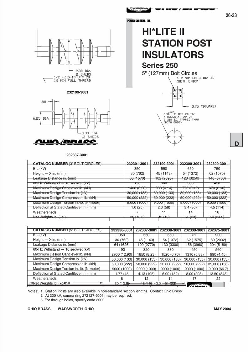
Notes: 1. Station Posts are also available in non-standard section lengths. Contact Ohio Brass.
2. At 230 kV, corona ring 272127-3001 may be required.
3. For through holes, specify code 3002.
CATALOG NUMBER (5" BOLT CIRCLES)
BIL (kV)
Height — X in. (mm)
Leakage Distance in. (mm)
60-Hz Withstand — 10 sec/wet (kV)
Maximum Design Cantilever lb. (kN)
Maximum Design Tension lb. (kN)
Maximum Design Compression lb. (kN)
Maximum Design Torsion in.-lb. (N-meter)
Deflection at Stated Cantilever in. (mm)
Weathersheds
Net Weights lb. (kg.)
232375-3001
900
80 (2032)
204 (5180)
560
990 (4.45)
30,000 (133)
35,000 (156)
9,000 (66.7)
13.50 (343)
22
72 (32.7)
CATALOG NUMBER (3" BOLT CIRCLES)
BIL (kV)
Height — X in. (mm)
Leakage Distance in. (mm)
60-Hz Withstand — 10 sec/wet (kV)Maximum Design Cantilever lb. (kN)
Maximum Design Tension lb. (kN)
Maximum Design Compression lb. (kN)
Maximum Design Torsion in.-lb. (N-meter)
Deflection at Stated Cantilever in. (mm)
Weathersheds
Net Weights lb. (kg.)
232301-3001
350
30 (762)
63 (1570)
1901400 (6.23)
30,000 (133)
50,000 (222)
9,000 (1000)
1.0 (25)
7
30 (13.6)
232300-3001
650
54 (1372)
128 (3250)
380770 (3.42)
30,000 (133)
50,000 (222)
9,000 (1000)
3.4 (86)
14
51 (23)
232309-3001
750
62 (1575)
148 (3760)
430670 (2.98)
30,000 (133)
50,000 (222)
9,000 (1000)
4.5 (114)
16
54 (24.5)
232199-3001
550
45 (1143)
102 (2590)
300930 (4.14)
30,000 (133)
50,000 (222)
9,000 (1000)
2.3 (58)
11
42 (19)
232336-3001
350
30 (762)
64 (1626)
190
2900 (12.90)
30,000 (133)
50,000 (222)
9000 (1000)
1.77 (45
8
30 (13.6)
232337-3001
550
45 (1143)
109 (2770)
320
1850 (8.23)
30,000 (133)
50,000 (222)
9000 (1000)
4.13 (105)
12
42 (19)
232338-3001
650
54 (1372)
130 (3300)
380
1520 (6.76)
30,000 (133)
50,000 (222)
9000 (1000)
6.00 (152)
14
51 (23)
232339-3001
750
62 (1575)
156 (3960)
450
1310 (5.83)
30,000 (133)
50,000 (222)
9000 (1000)
8.00 (203)
17
54 (24.5)
HI*LITE IISTATION POSTINSULATORSSeries 2505" (127mm) Bolt Circles
232337-3001
232199-3001

7/16/2019 OhioBrass - 26-HiLite Insulators
http://slidepdf.com/reader/full/ohiobrass-26-hilite-insulators 34/36
OHIO BRASS – WADSWORTH, OHIO
26-34
MAY 2004
® ®
POWER SYSTEMS, INC.
7/16/2019 OhioBrass - 26-HiLite Insulators
http://slidepdf.com/reader/full/ohiobrass-26-hilite-insulators 35/36
26-
OHIO BRASS–
WADSWORTH, OHIO MAY 2004
® ®
POWER SYSTEMS, INC.
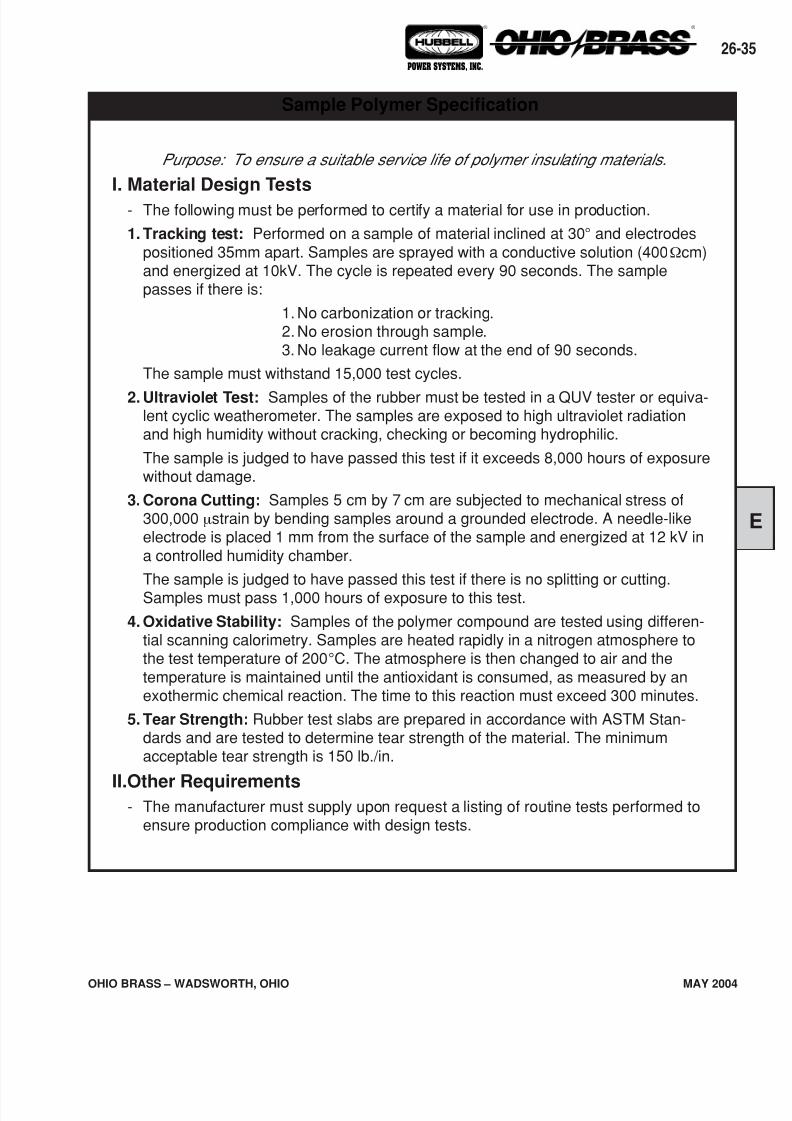
Purpose: To ensure a suitable service life of polymer insulating materials.
I. Material Design Tests
- The following must be performed to certify a material for use in production.
1. Tracking test: Performed on a sample of material inclined at 30° and electrodespositioned 35mm apart. Samples are sprayed with a conductive solution (400Ωcm)and energized at 10kV. The cycle is repeated every 90 seconds. The samplepasses if there is:
1. No carbonization or tracking.2. No erosion through sample.3. No leakage current flow at the end of 90 seconds.
The sample must withstand 15,000 test cycles.
2. Ultraviolet Test: Samples of the rubber must be tested in a QUV tester or equiva-lent cyclic weatherometer. The samples are exposed to high ultraviolet radiationand high humidity without cracking, checking or becoming hydrophilic.
The sample is judged to have passed this test if it exceeds 8,000 hours of exposurewithout damage.
3. Corona Cutting: Samples 5 cm by 7 cm are subjected to mechanical stress of300,000 µstrain by bending samples around a grounded electrode. A needle-likeelectrode is placed 1 mm from the surface of the sample and energized at 12 kV ina controlled humidity chamber.
The sample is judged to have passed this test if there is no splitting or cutting.Samples must pass 1,000 hours of exposure to this test.
4. Oxidative Stability: Samples of the polymer compound are tested using differen-tial scanning calorimetry. Samples are heated rapidly in a nitrogen atmosphere tothe test temperature of 200°C. The atmosphere is then changed to air and thetemperature is maintained until the antioxidant is consumed, as measured by anexothermic chemical reaction. The time to this reaction must exceed 300 minutes.
5. Tear Strength: Rubber test slabs are prepared in accordance with ASTM Stan-dards and are tested to determine tear strength of the material. The minimumacceptable tear strength is 150 lb./in.
II.Other Requirements- The manufacturer must supply upon request a listing of routine tests performed to
ensure production compliance with design tests.
Sample Polymer Specification
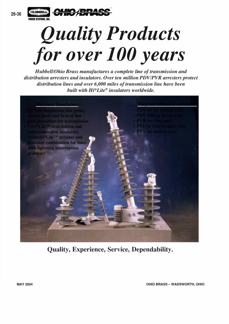
7/16/2019 OhioBrass - 26-HiLite Insulators
http://slidepdf.com/reader/full/ohiobrass-26-hilite-insulators 36/36
26-36
® ®
POWER SYSTEMS, INC.
Hubbell/Ohio Brass manufactures a complete line of transmission and
distribution arresters and insulators. Over ten million PDV/PVR arresters protect
distribution lines and over 6,000 miles of transmission line have been
built with Hi*Lite® insulators worldwide.
Quality Products
for over 100 years
Polymer-Housed Arresters• PDV-65 for normal duty
• PDV-100 for heavy duty
• PVR for riser pole
• PVI for intermediate class
• PVN for station class
Polymer Insulators• Hi*Lite suspension, line posts,
station posts and braced line
post assemblies for transmission
• Veri*Lite™ distribution and
subtransmission insulators
• Protecta*Lite™ arrester and
insulator combination for lines
with lightning interruption
problems
Quality, Experience, Service, Dependability.