ohm-electrics klantenteller
DESCRIPTION
Ohm-ElectricsTRANSCRIPT

Peoplecounter Installation Manual
Date: 30-‐04-‐2009
Version: 1.1
Author: Luc Saeys

1 Peoplecounter Install Manual
1. Equipments a. PLC case
b. IR sender + IR receiver
c. One UTP patch cable (+/-‐1m) to connect the PLC case Ethernet connection with a
free connection on the store router (not included in the delivery)
d. Two UTP cables to connect the Sender1 port with the IR sender and to connect the
Receiver1 port to the IR Receiver (not included in the delivery)
e. Material to install the PLC case and the IR sender/receiver (not included in the delivery)
2 Peoplecounter Install Manual
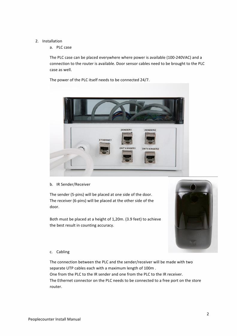
2. Installation a. PLC case
The PLC case can be placed everywhere where power is available (100-‐240VAC) and a connection to the router is available. Door sensor cables need to be brought to the PLC case as well.
The power of the PLC itself needs to be connected 24/7.
b. IR Sender/Receiver
The sender (5-‐pins) will be placed at one side of the door. The receiver (6-‐pins) will be placed at the other side of the door. Both must be placed at a height of 1,20m. (3.9 feet) to achieve the best result in counting accuracy.
c. Cabling
The connection between the PLC and the sender/receiver will be made with two separate UTP cables each with a maximum length of 100m . One from the PLC to the IR sender and one from the PLC to the IR receiver. The Ethernet connector on the PLC needs to be connected to a free port on the store router.
3 Peoplecounter Install Manual
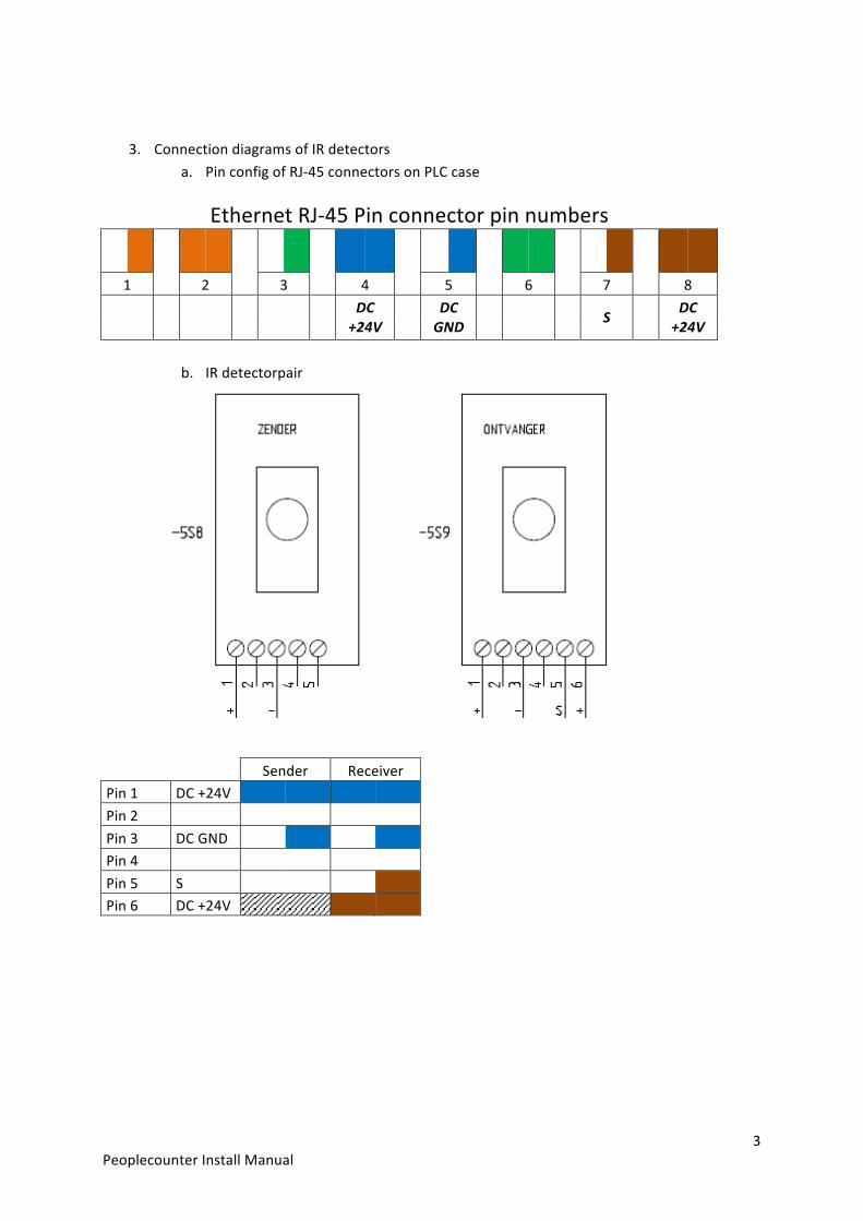
3. Connection diagrams of IR detectors a. Pin config of RJ-‐45 connectors on PLC case
Ethernet RJ-‐45 Pin connector pin numbers
1 2 3 4 5 6 7 8
DC +24V
DC GND
S
DC +24V
b. IR detectorpair
Sender Receiver Pin 1 DC +24V Pin 2 Pin 3 DC GND Pin 4 Pin 5 S Pin 6 DC +24V

4 Peoplecounter Install Manual
4. Overview