official autodesk training guide learning autodesk maya...
TRANSCRIPT

FREE MODELSFrom TurboSquidValue $298.00 USD
The Special Effects HandbookA hands-on introduction to key tools and techniques in Autodesk® Maya® 2009 software, based on Michael Sormann’s short film entitled, Theme Planet.
Official Autodesk Training Guide
LearningAutodesk® Maya®
2009
Project 01 Lesson 01 Materials 17
Lesson 02 Textures 47
Project 02 Lesson 03 Lights 79
Lesson 04 Shadows 99
Lesson 05 Cameras 131
Lesson 06 Raytracing 15 1
Project 03 Lesson 07 Controlling Renders 163
Lesson 08 Special Effects and Compositing 185
Lesson 09 Hardware Rendering 207
Lesson 10 Vector Rendering 217
Lesson 11 Maya Paint Effects 233
Table of Contents
Project 04 Lesson 12 Caustics and Global Illumination 244
Lesson 13 Final Gathering and HDRI 255
Lesson 14 mental ray Shaders 275

Project 05 Lesson 15 Maya Dynamics 311
Lesson 16 Rigid Body Dynamics 317
Lesson 17 Rigid Body Constraints 331
Lesson 18 Rigid Body Optimization 343
Project 06 Lesson 19 Introduction to Particles 363
Lesson 20 Rigid Bodies and Particles 399
Lesson 21 Particle Collisions 405
Lesson 22 Particle Expressions 421
Lesson 23 The emit Function 439
Lesson 24 Advanced Particle Expressions 457
Lesson 25 Goals 471
Lesson 26 Particle Instancing 485
Project 07 Lesson 27 Rendering Particles 507
Lesson 28 Compositing 533
Project 08 Lesson 29 Maya Fluids 545
Lesson 30 Maya Fur 565
Lesson 31 Maya Hair 583
Lesson 32 Maya nDynamics 605
Index 626

MaterialsA material is a set of instructions that describes how the surface of an object will look when rendered. It is not just a collection of attributes you can texture-map, but also a mathematical description of how light will behave when it strikes the surface. A material’s attributes allow you to fine-tune its look, whether it is a cartoon effect or photorealism.
In this lesson, you will learn the following:
What an IPR render is•
The basics of materials and shading networks•
What a specular highlight is and how to use it•
What the following types of shaders are and how to use them•
anisotropic shaders
layered shaders
ramp shaders
shading maps
surface shaders
Less
on 0
1

Proj
ect
01
LEARNING AUTODESK MAYA 2009 | THE SPECIAL EFFECTS HANDBOOK
16
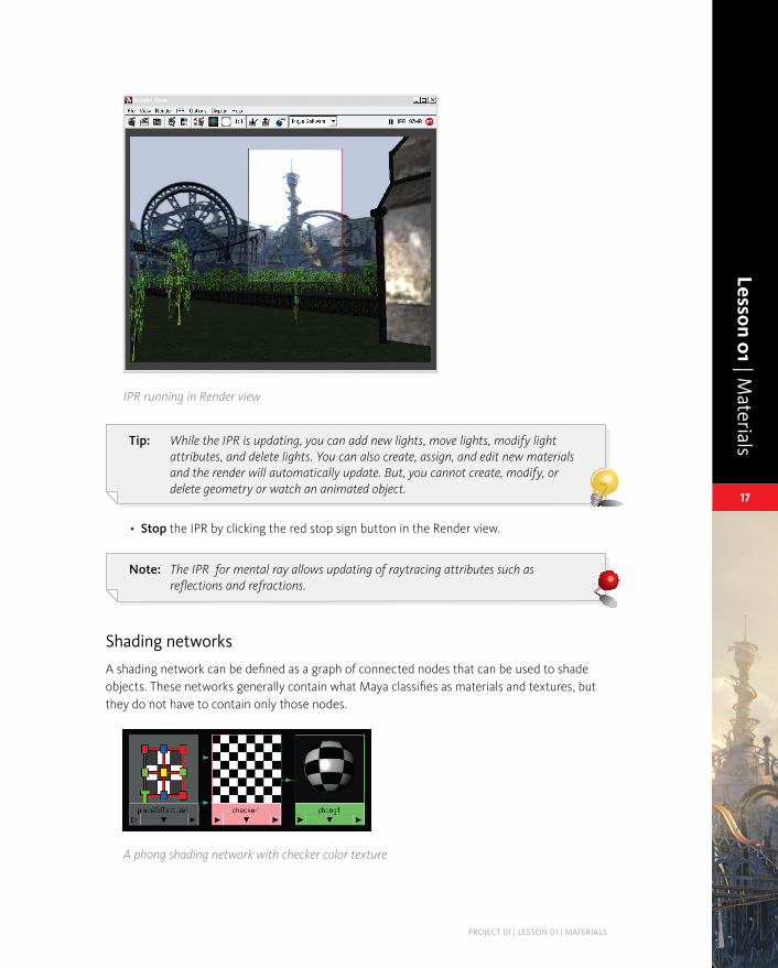
IPR
IPR stands for Interactive Photorealistic Rendering and is available for both mental ray and Autodesk® Maya® renderers. IPR is a type of software rendering that allows you to adjust shading and lighting attributes and see the updates in real-time. When you do an IPR render, it writes out a file (known as a deep raster file), that contains all the sample information for each pixel in the image. This file is written to the renderData/iprImages directory. It will have a name like _ipr.iff. This file is similar to the file that is written out when you do a normal render in the Render view, in that it is overwritten every time you do a new IPR render. As long as the current project stays the same, the file will be overwritten when an IPR render is started in that user session.
However, IPR does not prefix the camera name to the filename, as a normal render does. This means that if you change cameras and do an IPR render, the deep raster file will overwrite the same file. A regular render will add the prefix of the camera to the file and generate a new file. To save the Maya IPR file permanently so that it will not be overwritten, choose File → Save IPR File in the Render view window. This is useful if you are working on a large scene and the IPR file takes several minutes to generate. If this is the case, you can save out the IPR file and work on other things and still return to it at a later time. If you have saved out an IPR file, you can use fcheck to view the image component of the file. If you use the mental ray for Maya IPR, the IPR images will be saved in the Images directory.
Tip: IPR files can be quite large and will consume large amounts of disk space. It is a good idea to delete these files if you do not need them.
IPR rendering1 Open• the scene file called 01-background.ma from the support_files/project1/scenes directory on the DVD-ROM.
Click the • IPR Render button at the top of the main interface or in the Render view.
The scene is rendered, and then a message appears at the bottom of the Render view that says:
Select a region to begin tuning
Click+drag• to draw a region around the portion of the image you want to tune.
You can now begin tuning lights and materials to see the IPR update automatically.
Lesson 01 | Materials
PROjECT 01 | LESSON 01 | MATERIALS
17
L01_003_network.tif
L01_002_ipr.tif
IPR running in Render view
Tip: While the IPR is updating, you can add new lights, move lights, modify light attributes, and delete lights. You can also create, assign, and edit new materials and the render will automatically update. But, you cannot create, modify, or delete geometry or watch an animated object.
Stop• the IPR by clicking the red stop sign button in the Render view.
Note: The IPR for mental ray allows updating of raytracing attributes such as reflections and refractions.
Shading networks
A shading network can be defined as a graph of connected nodes that can be used to shade objects. These networks generally contain what Maya classifies as materials and textures, but they do not have to contain only those nodes.
A phong shading network with checker color texture

Proj
ect
01
LEARNING AUTODESK MAYA 2009 | THE SPECIAL EFFECTS HANDBOOK
18
The idea behind the Maya architecture is to have many simple nodes that can be connected in a virtually infinite number of combinations, rather than fewer and very complex nodes. For example, you will not find all of the conceivable light attributes on a single node; instead, you will have attributes for the light on one node, attributes for the light fog on another node and attributes for the light glow on a third node. While this may seem inconvenient at first, it will become apparent that this is a very powerful method for augmenting a shading network.
Shading groups
A shading group is a set of objects to be shaded with the shading network. Below is a diagram of a shading group called phong1SG (the SG stands for shading group). You can see a sphere connected to the shading group; these objects form the set that will be shaded by the shading network. In this case, the shading network is a phong material with a checker connected to it.
L01_004_shadinggroup.tif
A shading group with attached shading network and surfaces
Note: At render time, Maya determines which objects will be rendered by going to all of the shading groups and collecting all of the objects contained in each group. If an object is not a member of any shading group, it is not rendered.
Connecting shading networks to shading groups
The shading network is connected to a Port attribute on the shading group. In a typical workflow, this connection will be made automatically. Below is a view of the Attribute Editor showing the three ports on a shading group:

Lesson 01 | Materials
PROjECT 01 | LESSON 01 | MATERIALS
19
L01_005_ports.tif
The Attribute Editor for a shading group
Surface Material
This port is used to shade surfaces such as NURBS, polygons, and SubDs.
Volume Material
This port is used to shade volumes such as fogs and some particle types.
Displacement Material
This port is used for displacement mapping surfaces and is used in conjunction with the Surface Material port.
All shading groups have the same three ports; this generality allows any shading group to shade any type of object. Each port has a shading engine associated with it that will evaluate the network attached to it.
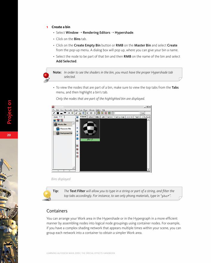
Bins
The Hypershade contains a Bins tab. Bins allow users to organize their networks into groups under specific headings. For instance, if you have several characters in a scene, each of which has a number of materials assigned to it, you may want to create a separate bin for each character to store all associated materials.
Proj
ect
01
LEARNING AUTODESK MAYA 2009 | THE SPECIAL EFFECTS HANDBOOK
20
Create a bin1 Select • Window → Rendering Editors → Hypershade.
Click on the • Bins tab.
Click on the • Create Empty Bin button or RMB on the Master Bin and select Create from the pop-up menu. A dialog box will pop up, where you can give your bin a name.
Select the node to be part of that bin and then • RMB on the name of the bin and select Add Selected.
Note: In order to see the shaders in the bin, you must have the proper Hypershade tab selected.
To view the nodes that are part of a bin, make sure to view the top tabs from the • Tabs menu, and then highlight a bin’s tab.
Only the nodes that are part of the highlighted bin are displayed.
L01_006_bins.tif
Bins displayed
Tip: The Text Filter will allow you to type in a string or part of a string, and filter the top tabs accordingly. For instance, to see only phong materials, type in “pho*”.
Containers
You can arrange your Work area in the Hypershade or in the Hypergraph in a more efficient manner by assembling nodes into logical node groupings using container nodes. For example, if you have a complex shading network that appears multiple times within your scene, you can group each network into a container to obtain a simpler Work area.

Lesson 01 | Materials
PROjECT 01 | LESSON 01 | MATERIALS
21
Create a container1 Select • Window → Rendering Editors → Hypershade.
Select any object with a shading network assigned to it.•
Select • Graph → Graph Material on Selected Objects.
Select all the nodes that are part of the shading network except the shading group node.•
RMB • on the selection and select Create container from selected.
The nodes will be collapsed into a container node.
L01_006a_container.tif
A container in the Hypershade
Expand a container2 It is possible to expand a container in order to tweak its content.
Select a container.•
Click the • Expand selected container(s) button or select Edit → Expand Container.
L01_006b_expand.tif
The expanded container
Note: You can select nodes within a container and move them to organize the network display.

Proj
ect
01
LEARNING AUTODESK MAYA 2009 | THE SPECIAL EFFECTS HANDBOOK
22
Click the • Collapse selected container(s) button or select Edit → Collapse Container to collapse the network display.
Tip: You can also double-click on a container to toggle its display state.
Remove a container3 Click the • Remove selected container(s) button or select Edit → Remove Container to get the shading network out of the container.
The Maya Shader Library
After installing Maya, you can install the Maya Shader Library from the installation CD. This library is a collection of scene files consisting of over sixty shading networks, including materials and file textures. These networks can be used as-is or as a basis to create your own materials or shaders.
Once the Shader Library is installed, you can preview the library directly in the Hypershade via the Shader Library tab located in the top panel. To use one of the shaders from the library, simply MMB+drag it into the Hypershade or RMB on it and choose Import Maya file. Once you have dragged or imported the file, it will appear in the Materials tab and can be assigned or manipulated like any other material.
Note: You cannot assign Shader Library materials directly from the Shader Library tab.
Materials
A material is essentially a shading model that calculates the surface characteristics and determines how a surface will be shaded. The terms shader and material are used interchangeably; both are correct for this description. The common industry term is shader, and you will find this term throughout the book.
The single most important thing to do when creating an effective material is to concentrate on how the object’s highlight appears. This one factor can dramatically improve the look of the material even before any textures are applied. Look around you and take note of the various ways light falls across surfaces. Notice how shiny objects have a bright small highlight and how a dull surface has barely any highlight at all.
You will now take a closer look at how light reflects off a surface. The following diagram illustrates how some portion of incident light is scattered as it reflects, and some portion of the light can be reflected at a more consistent angle. The light reflected at a consistent angle results in an intense bright region called a specular highlight. The scattered light is referred to as diffuse light.

Lesson 01 | Materials
PROjECT 01 | LESSON 01 | MATERIALS
23
L01_007_light.tif
Reflected light
Components of refracted light
In reality, the specular component and the diffuse component of the total reflected light will vary depending on the characteristics of the surface.
In Maya, the diffuse component and the specular component are controlled separately, which gives you the flexibility to simulate virtually any real-world surface.
Light source
Reflected light
Eye
L01_008_diffuse.tif
L01_009_specular.tifDiffuse component of reflected light
Specular component of reflected light
Proj
ect
01
LEARNING AUTODESK MAYA 2009 | THE SPECIAL EFFECTS HANDBOOK
24
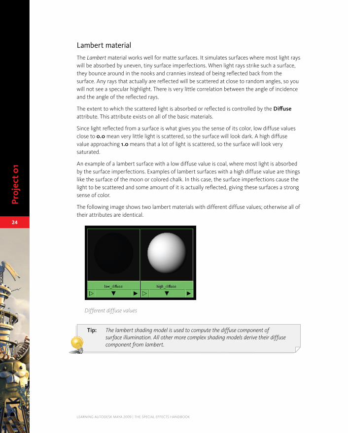
Lambert material
The Lambert material works well for matte surfaces. It simulates surfaces where most light rays will be absorbed by uneven, tiny surface imperfections. When light rays strike such a surface, they bounce around in the nooks and crannies instead of being reflected back from the surface. Any rays that actually are reflected will be scattered at close to random angles, so you will not see a specular highlight. There is very little correlation between the angle of incidence and the angle of the reflected rays.
The extent to which the scattered light is absorbed or reflected is controlled by the Diffuse attribute. This attribute exists on all of the basic materials.
Since light reflected from a surface is what gives you the sense of its color, low diffuse values close to 0.0 mean very little light is scattered, so the surface will look dark. A high diffuse value approaching 1.0 means that a lot of light is scattered, so the surface will look very saturated.
An example of a lambert surface with a low diffuse value is coal, where most light is absorbed by the surface imperfections. Examples of lambert surfaces with a high diffuse value are things like the surface of the moon or colored chalk. In this case, the surface imperfections cause the light to be scattered and some amount of it is actually reflected, giving these surfaces a strong sense of color.
The following image shows two lambert materials with different diffuse values; otherwise all of their attributes are identical.
L01_010_highlowdiffuse.tif
Different diffuse values
Tip: The lambert shading model is used to compute the diffuse component of surface illumination. All other more complex shading models derive their diffuse component from lambert.

Lesson 01 | Materials
PROjECT 01 | LESSON 01 | MATERIALS
25
Phong, phongE, and blinn
Very smooth surfaces such as glass, mirrors, and chrome will have a very low diffuse value, approaching zero. This is because they reflect very little scattered light. The light does not get scattered because there are few surface imperfections that would cause it to bounce at random angles. Instead, most of the light rays are reflected off the surface at a similar angle, resulting in a specular highlight. Because the lambert material does not simulate the specular component of surface illumination, for these types of surfaces you can choose from several other materials: Phong, PhongE, and Blinn.
Both phong and blinn shading models approximate the surface physics of incident light reflecting off a smooth surface. They are named after computer scientists Bui Tuong Phong and James Blinn.
The Specular Shading attributes on these three material types control how much the light rays cohere as they are reflected off the surface. If the light rays are reflected at close to the same angle, a tight highlight results. If the rays are more scattered, a bigger and softer highlight will result. If the rays were to become scattered enough, you would end up with the look of the lambert shading model.
At the other extreme, these shading models can simulate a mirror’s almost perfectly smooth surface where very little light is absorbed and the reflected rays are very coherent.
Unlike the diffuse attribute, which is common to all of these materials, the attributes that control the specular highlight appearance have different names on each material.
Phong
Cosine Power affects the size of highlights on the surface. This attribute can be thought of as shininess. Low numbers create big highlights while high numbers produce small highlights, typically seen on very shiny surfaces.
PhongE
Roughness and Highlight Size work together to affect the size and look of the highlight.
Blinn
Eccentricity affects the size of highlights on the surface. Very shiny surfaces will need low values to produce a small and strong highlight, while surfaces like brushed metal will need higher values to produce a large highlight.

Proj
ect
01
LEARNING AUTODESK MAYA 2009 | THE SPECIAL EFFECTS HANDBOOK
26
Using blinn, phong, or phongE?
While all three of these materials produce specular highlights, they each provide very different visual results. This visual impact is likely to be the determining factor in terms of which one to use, although it is worth noting that there is a slight increase in rendering time associated with using more complex materials such as blinn. The order of rendering performance from fastest to slowest is:
phongE•
phong•
blinn•
L01_011_types.tif
Comparison of materials phong, phongE, and blinn
Phong is less complex than blinn; it does not take into account changes in specularity due to the angle at which you are viewing the surface.
Blinn is a more sophisticated and true-to-life shading model, in which surfaces appear shinier at more severe angles. This can be controlled by the Specular Roll Off attribute on the blinn material. Specular Roll Off also allows surfaces to reflect more of their surroundings when viewed at glancing angles. The following images show the effect of this attribute on reflectivity:
L01_012_rolloff.tif
Effect of Specular Roll Off on reflectivity (Reflected Color mapped with checker)
0.01 0.3 1.0

Lesson 01 | Materials
PROjECT 01 | LESSON 01 | MATERIALS
27
Tip: Use a Specular Roll Off value of 0.3 to simulate a wet surface, such as wet paint.
You will also see that the Specular Roll Off affects the transition between the Specular Color and the Diffuse Color.
0.3 0.7 1.0
L01_013_specular.tif
Effect of Specular Roll Off on transition from Specular Color to Diffuse Color
Tip: The soft highlights on blinn surfaces are less likely to exhibit roping or flickering than the harder highlights on phong surfaces. Use the blinn material for surfaces with bump or displacement to reduce highlight roping or flickering.
Specialized surface materials
So far you have looked at the most frequently used materials. There are several other materials in Maya. These materials are:
anisotropic shaders•
layered shaders•
ramp shaders•
shading maps•
surface shaders•
Use Background• shaders
The anisotropic shader
The purpose of the anisotropic shader is to simulate surfaces that have micro-facet grooves when the specular highlight tends to be perpendicular to the direction of the grooves. If an anisotropic surface is spun against the grooves, the shape and location of the highlight will change depending on how the groove direction changes. Examples of uses for this material are satin, silk, nylon, CDs, etc.

Proj
ect
01
LEARNING AUTODESK MAYA 2009 | THE SPECIAL EFFECTS HANDBOOK
28
L01_014_satin.tif
Anisotropic material
Note: The image shown above was rendered from the file 01-satinOrnament.ma from the support_files. There are also other anisotropic shaders for you to render in the Hypershade.
In the following exercise, you will create and apply an anisotropic material to a falling CD, reproducing the rainbow highlights characteristic of a CD’s underside. Later in this lesson you will complete the CD using a layered shader.
Scene file1 Open• the scene file called 01-anisoCD_01.ma.
This file contains a NURBS disk that was animated as a rigid body colliding with a ground object. The simulation has been baked to allow scrubbing in the Time Slider. The CD geometry is made up of different pieces so different materials can be applied to the various sections. All pieces are parented under one rigid body node.
Layout2 Select • Panels → Saved Layouts → Hypershade/Render/Persp.
In the • Perspective view, select Panels → Perspective → camera.
The camera is already animated for this exercise. Make sure when you render that you are rendering this camera.

Lesson 01 | Materials
PROjECT 01 | LESSON 01 | MATERIALS
29
Create and assign an anisotropic material3 Use the • Create menu in the Hypershade to create an Anisotropic material.
Assign• it to mainCDbody and mediumRing.
Tune the anisotropic material4 Set the following values:•
Diffuse to 0.05;
Angle to 180;
Spread X to 37;
Spread Y to 0.1;
Roughness to 0.4;
Fresnel Index to 8.4.
Note: The Diffuse value should be low because this material is meant to simulate the smooth plastic coating on the underside of a CD. Nearly all reflected light from a very smooth surface will be represented by the specular component. The microgrooves in this coating will produce anisotropic highlights controlled by the following attributes.
Spread X
Controls how much the grooves spread out in the X-direction. The range is from 0.1 to 100. (The X-direction is the surface’s U-direction, rotated counterclockwise by the Angle attribute.) When this value is increased, the specular highlight shrinks in that direction, making the surface appear smoother. When the value is decreased, the highlight spreads out more in that direction, making the surface appear less smooth.
Spread Y
Controls how much the grooves spread out in the Y-direction. It ranges from 0.1 to 100. (The Y-direction is perpendicular to the X-direction.) The effect of this attribute is similar to Spread X.
Roughness
Controls the overall roughness of the surface. It ranges from 0.01 to 1.0, with larger values giving a rougher appearance. As this value is increased, the specular highlights are more spread out. This value will also affect the reflectivity of the material if the Anisotropic Reflectivity is turned On.
Angle
Defines the X and Y directions on the surface relative to the surface’s intrinsic U and V directions. X is the U direction, rotated counterclockwise by the Angle attribute. These X and Y directions are used by the shader to place the microgrooves that control the anisotropic properties of the shader. This value ranges from 0 to 360 degrees.

Proj
ect
01
LEARNING AUTODESK MAYA 2009 | THE SPECIAL EFFECTS HANDBOOK
30
Fresnel Refractive Index
Affects the look of the anisotropic highlight. (If the material is transparent and you are raytracing, it does not affect the way light from other objects bends when passing through the material.) As you increase this attribute, the highlight becomes brighter.
For transparent objects, you may want to set the Fresnel Index to match the object’s Refractive Index. This will give the most physically accurate result for the highlight.
If Anisotropic Reflectivity is turned On, the reflectivity of the material is calculated directly from its roughness. If this attribute is turned Off, the value in reflectivity is used instead.
IPR Render5 Go to frame • 57.
Select• IPR → IPR Render → camera.
A variety of highlights will be clearly visible in the render.
Define• a tuning region that encompasses the entire CD.
Note the quality and shape of the specular highlights. They are long and spread out across the surface, not round.
Map Specular Color6 The colored highlights that occur on CDs generally run from the inside of the CD to the outer edge and are typically a variety of colors from the visible light spectrum. On real CDs, these rainbow colors are caused by the diffraction of light (diffraction is the term for light splitting into its individual wavelengths as it passes through a medium such as a prism). A colored ramp texture will be used to fake the appearance of diffraction.
In the Hypergraph, show the top and bottom tabs.•
Select the • Textures tab.
MMB+drag• the rainbowSpecRamp texture onto the anisotropic1 material and select Specular Color from the drop-down menu.
Adjust the lighting7 When working with the anisotropic material, controlling the direction, distribution, and intensity of the lighting is vital to the success of the look you are trying to attain. Normally, multiple lights are required at various angles to the surface to see the anisotropic highlights well.
Increase the • Intensity of the spotLight2 to see the impact it has on the brightness of the highlights.
Move• the light to get a feel for the significance of its intensity and position relative to the surface.

Lesson 01 | Materials
PROjECT 01 | LESSON 01 | MATERIALS
31
L01_015_lightcd.tif
Position and intensity of spotLight2 modified
Save the file8 Save• the file, as you will complete the CD in the next exercise.
Note: A movie file called ansioCD.mov is available in the support_files folder to show the final results.
The layered shader
The layered shader can be used in two different ways. It can be used to layer materials, or to layer textures. Since there is a node specifically designed for layering textures that will be covered in the next lesson, you will experiment here only with the material layering capabilities.
When using the layered shader node, ask yourself if you need to see different material types on different areas of the same surface, or if you need to see different materials over the same area, such as a clear coat over car paint. If all you need is to overlay textures, you should use a layered texture rather than a layered shader. It is best to avoid using layered shaders unnecessarily because they are very expensive to render.
In this exercise, you will use the layered shader to combine two different materials.
Create materials to use as layers1 Before you can layer anything, you will need some simple materials.
In the • Hypershade, create a phong and a lambert material.
Set the • phong material to blue and the lambert material to red.
Map• a checker to the Transparency of the phong material.
Change the• Repeat UV attribute to 8 and 8 on the place2Dtexture node for the checker texture.
Create a layered shader node2 Create• a layered shader node.
Open the • Attribute Editor for the layeredShader node.

Proj
ect
01
LEARNING AUTODESK MAYA 2009 | THE SPECIAL EFFECTS HANDBOOK
32
Connect the materials to the layered shader node3 MMB+drag• the red lambert into the Layered Shader Attributes section.
MMB+drag• the blue phong into the Layered Shader Attributes section.
You will notice that each time you drag a material into the Layered Shader Attributes section, a new icon appears. These icons represent the layers.
Click on the small • x under the green layer icon to remove it.
The green icon is simply the default layer that you can get rid of once you have added your own layers.
Shuffle the layers4 You now have a layered shader with two materials in it. However, the swatch for the layered shader will appear to be completely red. This is because the red lambert material (without any transparency) is on top of the blue phong. You need to change the order of the layers in order to see the phong on top of the lambert.
In the • Attribute Editor for the layered shader, MMB+drag the lambert icon to the right of the phong icon.
You should now see both the layers in the swatch.
Tip: The order of the layers from left to right in the Attribute Editor represents the layer order from top to bottom on the surface.
IPR render the scene5 Create a • sphere.
Assign the • layeredShader to the sphere and launch an IPR render.
You will notice that the specular highlight falls across both the phong and the lambert regions of the surface (because even though the phong is transparent in those regions, its specular highlight is visible). This essentially defeats the purpose of using the layered materials.
Because different parts of the surface show different materials, you will need to change the layers again.
Manipulate the layers6 With IPR still running, • break the connection between the checker and phong in the Hypershade.
Create • a connection between the checker and the lambert’s Transparency attribute.

Lesson 01 | Materials
PROjECT 01 | LESSON 01 | MATERIALS
33
In the • Attribute Editor for the layered shader, swap the layers using the MMB as you did earlier.
Notice how in the IPR render, the specular highlight no longer shows on both the red and blue regions.
L01_017_render.tif
The IPR render
Tip: In more complex layered materials, you may need to apply a specular map to control the specular highlights on different layers.
The shading network should look similar to the following:
L01_016_layers.tif
Layered shader shading network

Proj
ect
01
LEARNING AUTODESK MAYA 2009 | THE SPECIAL EFFECTS HANDBOOK
34
Layered shader example
In this exercise, you will complete the CD that you started earlier in this chapter. You will use a layered shader to add the foil base visible under the clear grooved plastic on the underside of the CD.
Scene file 1 Use the file you saved earlier.•
OR
Open• the file named 01-anisoCD_02.ma.
Layout2 Select • Panels → Saved Layouts → Hypershade/Render/Persp.
In the • Perspective view, select Panels → Perspective → camera.
Create a layered shader3 Create a • Layered Shader material in the Hypershade.
Assign the • layeredShader1 to mainCDbody and mediumRing.
Open the • Attribute Editor for the layeredShader1.
MMB+drag • the anisotropic1 from the Hypershade into the Layered Shader Attribute section in the Attribute Editor for the layeredShader1.
Click on the • X under the green default layer icon to remove it.
Launch an IPR4 IPR render • frame 57 for test rendering throughout this exercise.
Create a blinn for the foil coating5 A blinn material will be used to create a silver/gold foil base coating on the CD. This layer will go under the anisotropic clear plastic coating.
Create• a Blinn material in Hypershade.
MMB+drag• the blinn into the Layered Shader Attribute section in the Attribute Editor for the layeredShader1.
At this point, you will not be able to see the blinn layer because the anisotropic material has no transparency.
Adjust the transparency on the anisotropic material6 Increase• the Transparency attribute on the anisotropic material to light grey for clear plastic.
This will reveal the blinn layer.

Lesson 01 | Materials
PROjECT 01 | LESSON 01 | MATERIALS
35
Tune the blinn material7 Adjust• the blinn attributes to get a silver look.
Tip: A good metallic material would use very low Diffuse, high Specular Roll Off, and low Eccentricity.
Add a reflection map8 Although the Diffuse, Eccentricity, and Specular Roll Off will be the primary attributes you tune on the blinn shader, adding a reflection map will enhance the visual impact of the foil.
Map• the Reflected Color attribute on the blinn with an Env Chrome from the Environment Textures section of the Create Render Node window.
This makes the CD appear to be reflecting a pseudo-environment.
Adjust• the Reflectivity attribute to increase or decrease the brightness of the reflection map.
Adjust• the colors on the envChrome texture if you do not want a blue look.
Make final adjustments9 If you have been test rendering at the same frame, you should check some other frames throughout the animation to make sure the values you are using provide expected results.
The camera angle and lighting position are important parts of the overall effect in this example. Experiment with different lighting to see how it affects the overall image.
The layered shader lets you combine the features of the various shading models to produce one final result. This extra flexibility does come at the expense of increased render times, but it also gives you results that may be otherwise difficult to achieve.
Save your work10 The final scene file is called • 01-anisoCD_03.ma.
Tip: The file anisoCDBlendCol.mb demonstrates an alternate method of achieving a similar appearance in the shading, but with the use of a blendColors utility node rather than a layered shader.

Proj
ect
01
LEARNING AUTODESK MAYA 2009 | THE SPECIAL EFFECTS HANDBOOK
36
The ramp shader
The ramp shader allows extra control over the way color changes with light angle, brightness, or the viewing angle (facing ratio). You can easily give your objects a flat, toon-like look by using the ramp shader.
This shader shares many attributes with other materials. All the color-related attributes are controlled by ramps. There are also graphs for defining Specular Roll Off and Reflectivity, improving performance by avoiding complex shading networks and making toon shading easier to achieve.
In this exercise, you will use a ramp shader to give some bouncing balls a flat, toon-like look.
Scene file 1 Open• the 01-bounce_01.ma scene file.
This file consists of a number of spheres that use dynamics to bounce on a floor.
Note: There is also a very large area light above the scene, which is why the illumination is so bright.
Create a ramp shader2 Create a • Ramp Shader material in the Hypershade.
Assign• the rampShader to all the spheres.
Open the • Attribute Editor for the rampShader.
You will notice that many of the common material attributes are controlled by ramps.
Edit the ramp attributes to create a toon shader3 Under the • Color section, create another ramp handle in the ramp field by clicking in the field.
Set the • Selected Position of this ramp handle to 0.15.
Select the • first ramp handle, and change its color to a bright blue.
Select • Interpolation and change it to None.
This will cause a crisp line between the different colors.
Select the • second ramp handle and set a darker blue.
Select • Interpolation and change it to None.
Note: To set a color using RGB values, open the Color Chooser window and under the Sliders section, change HSV to RGB. You can now use the three sliders as R, G, and B values.
Change • Color Input to Brightness.
Lesson 01 | Materials
PROjECT 01 | LESSON 01 | MATERIALS
37
L01_018b_sphereslines.tif
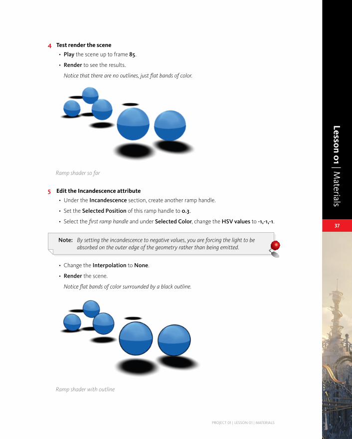
Test render the scene4 Play • the scene up to frame 85.
Render• to see the results.
Notice that there are no outlines, just flat bands of color.
L01_018a_spheres.tif
Ramp shader so far
Edit the Incandescence attribute5 Under the • Incandescence section, create another ramp handle.
Set the • Selected Position of this ramp handle to 0.3.
Select the • first ramp handle and under Selected Color, change the HSV values to -1,-1,-1.
Note: By setting the incandescence to negative values, you are forcing the light to be absorbed on the outer edge of the geometry rather than being emitted.
Change the • Interpolation to None.
Render• the scene.
Notice flat bands of color surrounded by a black outline.
Ramp shader with outline

Proj
ect
01
LEARNING AUTODESK MAYA 2009 | THE SPECIAL EFFECTS HANDBOOK
38
Add specular shading6 Under the • Specular Shading section, change Specularity to 1.0 and Eccentricity to 0.06.
This will change the size and brightness of the highlight.
L01_018c_spheresspec.tif
Ramp shader with strong specular
Note: The rectangular highlight is a result of the area light.
Save your work7 The final scene file is called • 01-bounce_02.ma.
Note: A movie file called bounce.avi is available on the accompanying DVD to show the final results.
Shading maps
A shading map is a node that allows you to remap the output from a material to create custom shading results. Recall that a material is a mathematical formula or set of instructions on how to shade the surface. The purpose of the shading map is to allow you to control the final shaded results to go beyond what is possible with standard materials.
A shading map allows complete control over the transition from the highlight to the shaded area of a surface. For example, you could achieve a cartoon look by mapping a ramp texture to get simple banded shading.

Lesson 01 | Materials
PROjECT 01 | LESSON 01 | MATERIALS
39
L01_019_shadingmap.tif
Shading map used with a ramp to produce toon-like blinn shading
Even more complex materials that have a translucent scattering layer can sometimes have a non-lambert falloff in diffuse intensity. This can be roughly simulated using the shading map to help get more natural-looking skin, for example.
This can be a very powerful feature because it allows you to remap the output of any shading model using a shading map. The remapped outputs of different shading models can then be recombined to create a new shading model.
Car paint exercise
Shading maps combined with a layered shader can be used to render realistic metallic paint. This allows for more variation in the look of the paint to avoid flat, monochromatic surfaces.
L01_020_car.tif
Clear coat and metallic highlight
Car paint can be represented in many ways. The purpose of this exercise is to show the use of a shading map for the control and placement of highlights on a car body.

Proj
ect
01
LEARNING AUTODESK MAYA 2009 | THE SPECIAL EFFECTS HANDBOOK
40
Scene file1 Open• the file named 01-car_01.ma.
Create shaders2 In the • Hypershade, create the following nodes:
Layered Shader;
Blinn;
Shading Map.
Add the shading map to the layered shader3 Open the • Attribute Editor for the layeredShader1.
MMB+drag • the shadingMap1 material from Hypershade to the Layered Shader Attributes section of the layeredShader1 node.
Remove• the green layer from the layeredShader1 node.
Assign• the layeredShader1 material to the car’s bodyGroup.
Tweak the shading map4 Select the • shadingMap1 material and open its Attribute Editor.
In the Shading Map Attributes section, you will notice two attributes called Shading Map Color and Color.
MMB+drag• the blinn1 material from the Hypershade to the Color attribute of the Shading Map Attributes section of the shadingMap1 node.
Set the following for • blinn1:
Color to black;
Diffuse to 0.0;
Eccentricity to 0.45;
Specular Roll Off to 0.42;
Specular Color to white.
Reflectivity to 0.0.

Lesson 01 | Materials
PROjECT 01 | LESSON 01 | MATERIALS
41
L01_021_ramp.tif
Clear coat layer6 Just as with a real car, a clear polished shader needs to be layered onto a matte base to create two separate highlight regions.
In the • Hypershade, create a Blinn material and set the following:
Color to black;
Transparency to white;
Diffuse to 0.0;
Eccentricity to 0.09;
Specular Roll Off to -10.0;
Reflectivity to 0.0;
Rename• the new blinn to clearCoat.
Ramp attributes
Add the clear coat to the layered shader7 MMB• the clearCoat material into the layeredShader1 node’s Attribute Editor.
Use the • MMB to reorder layers so the clear coat layer is in front of the base layer.
Reflection layer8 Although reflections can be added to the clear coat layer, custom reflection effects will be isolated with their own layer.
Create another • Blinn shader.
This shader will be used to control reflections.
Shading Map Color5 Map• the shadingMap1’s Shading Map Color attribute with a Ramp texture.
In the • Attribute Editor for the new ramp texture, define four handles as follows:
Handle at Position 1.0, RGB 1.0, 1.0, 1.0;
Handle at Position 0.9, RGB 0.71, 0.85, 0.85;
Handle at Position 0.1, RGB 0.22, 0.25, 0.32;
Handle at Position 0.0, RGB 0.0, 0.0, 0.0.

Proj
ect
01
LEARNING AUTODESK MAYA 2009 | THE SPECIAL EFFECTS HANDBOOK
42
Set the • Color to black.
Increase the • Transparency to white.
Decrease the • Eccentricity to 0.01 and increase the Specular Roll Off to 0.95.
This will ensure that the reflection will only be seen on angles oblique to the camera’s eye.
Click in the • Specular Color attribute and set its HSV to 0, 0, 4.
This will set the specular color to superwhite, which will allow you to clearly see the reflections caused by the high Specular Roll Off attribute.
Lower the • Reflectivity to 0.05 to avoid washed out reflections.
Tip: You must set Raytracing to On in the Render Settings to see reflections.
Rename• the new blinn to reflectivity.
Add the reflection blinn to the layered shader9 MMB• the reflection reflectivity into the layeredShader1 node’s Attribute Editor.
Use the • MMB to reorder layers so the reflection layer is in front of the clear coat layer.
L01_022_network.tif
A layered shader network using a shading map for control of highlights
Set your Render Settings for raytracing10 In the • Raytracing Quality section of the Render Settings window, turn Raytracing On.
Test render the scene. 11 The final scene file is called • 01-car_02.ma.

Lesson 01 | Materials
PROjECT 01 | LESSON 01 | MATERIALS
43
The surface shader
The surface shader is a lightweight pass-through node that simply allows you to translate the names of any node’s outputs to the names required for the shader to be a valid surface material.
What this means is that a node must directly connect to a surface material port of a shading group and have at least one of the following specially named output attributes to be a valid node:
outColor•
outTransparency•
outGlowColor•
If the node connected to the surface material port of a shading group does not have at least one of the above attributes, none of the objects assigned to that shading group will render.
Note: It does not matter which attribute of a node is connected to the surface material port of a shading group; only the outColor, outTransparency, and outGlowColor attributes of the connected node will be used.
The surface shader node is simply a means to translate an arbitrary network of Maya or user-written nodes with randomly named output attributes into what the renderer will recognize as a shading network.
Use Background shader
The Use Background shader becomes important in workflows involving compositing in the production pipeline. It allows a surface to mask other objects behind it by using the background color. This will be covered in further detail later in this book.
Conclusion
Materials are the foundation for shading your surfaces. A material is a set of instructions that describes how the surface of an object will look when rendered. It is not just a collection of texture maps, but also a description of how light will fall across the surface. Maya provides a number of tools to help you define the materials in your scene.
In the next lesson, you will learn about procedural and file textures that can be used in shading networks.