oil and gas operations, methods, current issues and trends
TRANSCRIPT
OIL AND GAS OPERATIONS,
METHODS, CURRENT ISSUES
AND TRENDS
by Karen J. Anspaugh
February 28, 2008
1
TABLE OF CONTENTS
I. Overview of Indiana Geology . . . . . . . . . . . . . . . . . . . . . . . . . . . . . . . . . . . 3
II. Resources in Indiana . . . . . . . . . . . . . . . . . . . . . . . . . . . . . . . . . . . . . . . . . . 4
A. Oil . . . . . . . . . . . . . . . . . . . . . . . . . . . . . . . . . . . . . . . . . . . . . . . . . . . . 4
1. Description of Oil . . . . . . . . . . . . . . . . . . . . . . . . . . . . . . . . . . 4
2. How Oil is Drilled . . . . . . . . . . . . . . . . . . . . . . . . . . . . . . . . . 5
3. Oil Drilling Units . . . . . . . . . . . . . . . . . . . . . . . . . . . . . . . . 7
B. Coalbed Methane . . . . . . . . . . . . . . . . . . . . . . . . . . . . . . . . . . . . . . . . 8
1. Description of Coalbed Methane. . . . . . . . . . . . . . . . . . . . . . . 8
2. How Coalbed Methane is Drilled . . . . . . . . . . . . . . . . . . . . . 9
3. Coalbed Methane Drilling Units . . . . . . . . . . . . . . . . . . . . . . 10
C. Natural Gas . . . . . . . . . . . . . . . . . . . . . . . . . . . . . . . . . . . . . . . . . . . . . 11
1. Thermogenic Methane . . . . . . . . . . . . . . . . . . . . . . . . . . . . . . 12
2. Biogenic Methane . . . . . . . . . . . . . . . . . . . . . . . . . . . . . . . . . . 12
III. Where Natural Gas is Found . . . . . . . . . . . . . . . . . . . . . . . . . . . . . . . . . . . . 12
A. Conventional Natural Gas Formation: Reservoirs . . . . . . . . . . . . . . 12
B. Unconventional Natural Gas Formations: New Albany Shale . . . . . 14
IV. Description of New Albany Shale . . . . . . . . . . . . . . . . . . . . . . . . . . . . . . . . 15
A. Location of the New Albany Shale . . . . . . . . . . . . . . . . . . . . . . . . . . 15
B. Characteristics of the New Albany Shale . . . . . . . . . . . . . . . . . . . . . 16
V. Recent Advances in Drilling . . . . . . . . . . . . . . . . . . . . . . . . . . . . . . . . . . . . . 18
A. General Drilling Technical Improvements . . . . . . . . . . . . . . . . . . . . 18
B. Shale Drilling Technical Improvements . . . . . . . . . . . . . . . . . . . . . 20
VI Recent Increase in Horizontal Drilling . . . . . . . . . . . . . . . . . . . . . . . . . . . . 22
A. Use of Larger Drilling units . . . . . . . . . . . . . . . . . . . . . . . . . . . . . . 23
B. Multilateral Wells . . . . . . . . . . . . . . . . . . . . . . . . . . . . . . . . . . . . . . 24
C. Forced Pooling . . . . . . . . . . . . . . . . . . . . . . . . . . . . . . . . . . . . . . . . . 25
D. Voluntary Pooled Units . . . . . . . . . . . . . . . . . . . . . . . . . . . . . . . . . . 25
VII. What a Drill Site Looks Like . . . . . . . . . . . . . . . . . . . . . . . . . . . . . . . . . . . 26
A. Impact of Operations on the Surface . . . . . . . . . . . . . . . . . . . . . . . 26
B. Examples of Rigs and Facilities . . . . . . . . . . . . . . . . . . . . . . . . . . . 27
VIII. Preparing Natural Gas for Sale . . . . . . . . . . . . . . . . . . . . . . . . . . . . . . . . . 29
A. Natural Gas Processing . . . . . . . . . . . . . . . . . . . . . . . . . . . . . . . . . . . 30
B. Transportation of Natural Gas to Point of Sale . . . . . . . . . . . . . . . . . 34
IX. Conclusion . . . . . . . . . . . . . . . . . . . . . . . . . . . . . . . . . . . . . . . . . . . . . . . . . 38
2
I. Overview of Indiana Geology
“Indiana is a large anticline [a fold or layer of rock bent upwards] that plunges to
the northwest. Consequently, the age and type of rocks in Indiana are governed by this
large structural feature.” Todd A. Thompson, Bedrock Geology of Indiana, http://igs.
indiana.edu/geology/structure/bedrockgeology/index.cfm. The youngest rocks, mostly
sandstones and shales, with some minor amounts of limestone and coal, are found in the
northeastern and southwestern parts of Indiana. The oldest rocks, which include
limestone, dolostones, and shales, are found in the southeastern part of Indiana. The type
of rock present at a location impacts how oil, natural gas, and coalbed methane are
trapped within the earth, and causes there to be larger oil reservoirs in parts of the state,
while other areas are dominated by more coalbed methane or natural gas deposits. The
type of rock formations will also impact how those resources may best be extracted from
the earth.
The structural features of Indiana are stable because the rocks remain relatively flat
and undisturbed; however, the thickness varies across the state. Rocks deposited in low
spots are called basins and rocks deposited in high spots are called arches. Indiana
includes parts of the Kankakee Arch and Cincinnati Arch, as well as parts of the
Michigan Basin and Illinois Basin. John A. Rupp, Tectonic Features of Indiana,
http://igs.indiana.edu/geology/structure/tectonicfeatures/index.cfm.

3
II. Resources in Indiana
Various natural resources are mined and produced in Indiana; however, discussion
herein is related to oil, coalbed methane, and natural gas.
A. Oil
1. Description of Oil. It is believed that oil was formed from the remains of
plants and animals, called “biomass.” Crude Oil Production, http://www.eia.doe.gov/
neic/infosheets/crudeproduction.html. As the remains were covered by layers of mud, silt
and sand, sedimentary rock formed. Geologic heat and the pressure of the rock then
turned the remains into crude oil, a liquid rich in hydrocarbons. “Movements in the earth
trapped . . . oil in the reservoir rocks between layers of impermeable rock, or cap rock,
such as granite or marble.” How Oil Drilling Works, Craig C. Freudenrich, Ph.D, http://
science.howstuffworks.com/oil-drilling.htm/printable. Folding, faulting and pinching out
are three ways in which the earth moves.
●Folding – horizontal movements press inward and move the rock layers
upward into a fold or anticline.
●Faulting – the layers of rock crack, and one side shifts upward or
downward.
●Pinching out – a layer of impermeable rock is squeezed upward into the
reservoir rock. Id.

4
Photo courtesy Institute of Petroleum
Oil reservoir rocks (red) and natural gas (blue) can be trapped by folding (left), faulting (middle) or pinching out (right).
http://science.howstuffworks.com/oil-drilling.htm
2. How Oil is Drilled. Most oil produced in Indiana is from sandstone and
limestone rock. The Trenton Field has seen prolific oil production. Said field is
composed of Ordovician age limestone and is located in east-central Indiana, where the
limestone has an average thickness of 100 feet and an average depth of 900 feet. Oil has
also been produced from oil and gas fields located in southwestern Indiana. Oil and Gas
in Indiana, http://www.in.gov/dnr/dnroil/pdf/O&G_in_Indiana.pdf.
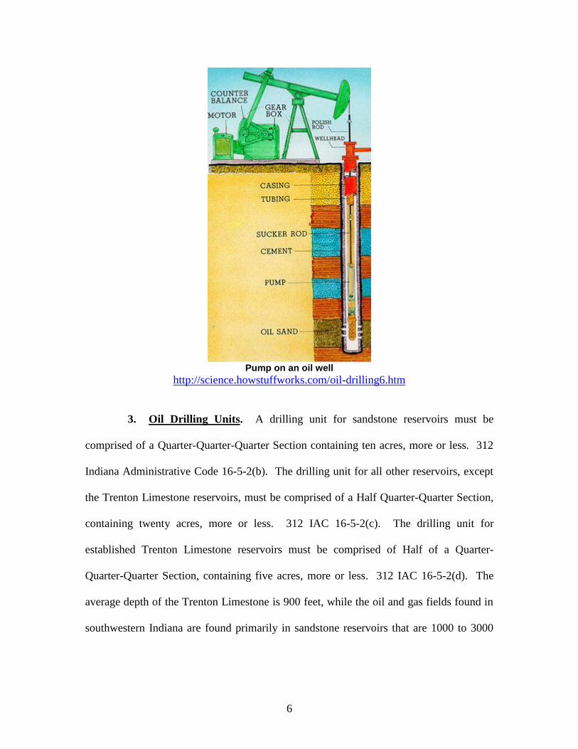
To extract oil, vertical wells are drilled into oil reservoirs. Petroleum (Oil) – A
Fossil Fuel, http//:www.eia.doe.gov/kids/energyfacts/sources/non-renewable/oil.html.
When a reservoir is first drilled, there may be enough natural pressure in the reservoir to
force the oil to the surface so that “natural lift” production methods may be used. When
the natural pressure dissipates, the oil must then be pumped out using “artificial lift”
created by mechanical pumps. Eventually, these “primary” methods become ineffective
and “secondary” methods of production must be used. One secondary method of
production involves injecting water into the reservoir to increase pressure, which forces
the oil to the wellbore. Id.

5
Anatomy of an Oil Rig
6
Pump on an oil well
http://science.howstuffworks.com/oil-drilling6.htm
3. Oil Drilling Units. A drilling unit for sandstone reservoirs must be
comprised of a Quarter-Quarter-Quarter Section containing ten acres, more or less. 312
Indiana Administrative Code 16-5-2(b). The drilling unit for all other reservoirs, except
the Trenton Limestone reservoirs, must be comprised of a Half Quarter-Quarter Section,
containing twenty acres, more or less. 312 IAC 16-5-2(c). The drilling unit for
established Trenton Limestone reservoirs must be comprised of Half of a Quarter-
Quarter-Quarter Section, containing five acres, more or less. 312 IAC 16-5-2(d). The
average depth of the Trenton Limestone is 900 feet, while the oil and gas fields found in
southwestern Indiana are found primarily in sandstone reservoirs that are 1000 to 3000
7
feet deep. Oil and Gas in Indiana, http://www.in.gov/dnr/dnroil/pdf/O&G.in_
Indiana.pdf.
B. Coalbed Methane
1. Description of Coalbed Methane. During the coalification process, plant
material is progressively converted into coal. Coalbed Methane – An Untapped Energy
Resource and an Environmental Concern, http://energy.usgs.gov/factsheet/Coalbed/
coalmeth.html. This process generates large amounts of methane-rich gas that is stored
within the coal.
Coalbed methane has recently been recognized as a potentially new source of
natural gas. John A. Rupp, Coalbed Methane Development in Indiana: Current Status
and Future Challenges, http://igs.indiana.edu/pdms/dl/Reports/Coalbed%20Methane%
20Development2.pdf. “Most gas in coal is stored on the internal surfaces of organic
matter.” Coalbed Methane – An Untapped Energy Resource and an Environmental
Concern, http://energy.usgs.gov/factsheet/Coalbed/coalmeth.html. Because coal has a
large internal surface area, coal can store six to seven times more gas than “the equivalent
rock volume of a conventional gas reservoir.”
8
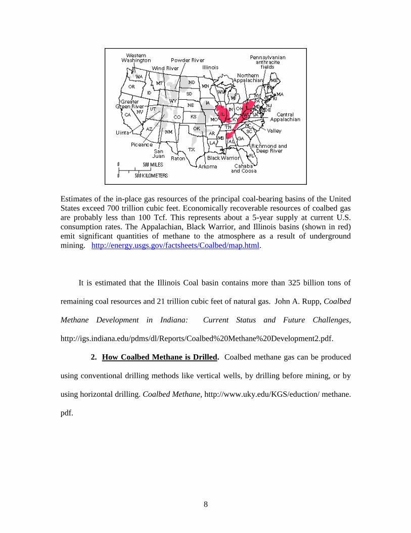
Estimates of the in-place gas resources of the principal coal-bearing basins of the United
States exceed 700 trillion cubic feet. Economically recoverable resources of coalbed gas
are probably less than 100 Tcf. This represents about a 5-year supply at current U.S.
consumption rates. The Appalachian, Black Warrior, and Illinois basins (shown in red)
emit significant quantities of methane to the atmosphere as a result of underground
mining. http://energy.usgs.gov/factsheets/Coalbed/map.html.
It is estimated that the Illinois Coal basin contains more than 325 billion tons of
remaining coal resources and 21 trillion cubic feet of natural gas. John A. Rupp, Coalbed
Methane Development in Indiana: Current Status and Future Challenges,
http://igs.indiana.edu/pdms/dl/Reports/Coalbed%20Methane%20Development2.pdf.
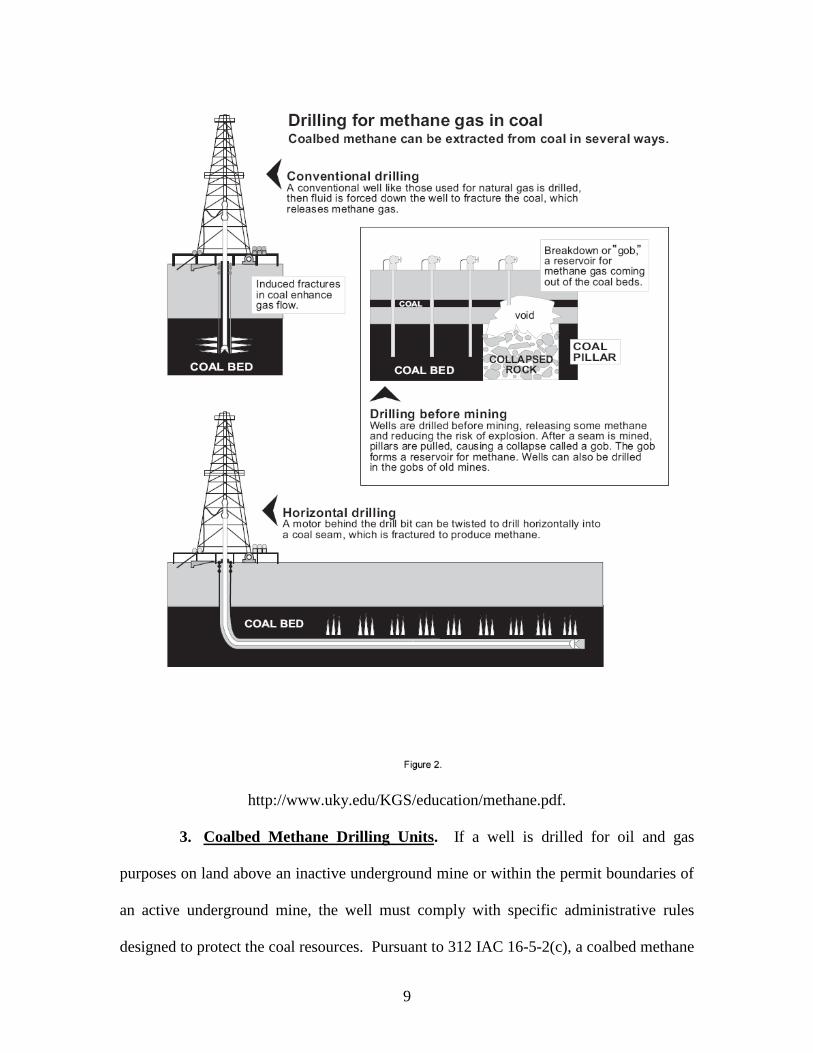
2. How Coalbed Methane is Drilled. Coalbed methane gas can be produced
using conventional drilling methods like vertical wells, by drilling before mining, or by
using horizontal drilling. Coalbed Methane, http://www.uky.edu/KGS/eduction/ methane.
pdf.
9
http://www.uky.edu/KGS/education/methane.pdf.
3. Coalbed Methane Drilling Units. If a well is drilled for oil and gas
purposes on land above an inactive underground mine or within the permit boundaries of
an active underground mine, the well must comply with specific administrative rules
designed to protect the coal resources. Pursuant to 312 IAC 16-5-2(c), a coalbed methane
10
well that is not located in the Trenton limestone reservoir and which is drilled to less than
1,000 feet, requires that the drilling unit be comprised of a Half of a Quarter-Quarter Section,
containing twenty (20) acres, more or less. Coalbed methane wells have been drilled in
Vigo, Sullivan, Knox and Gibson counties in Indiana. John A. Rupp, Coalbed Methane
Development in Indiana: Current Status and Future Challenges, http://igs.indiana.
edu/pdms/dl/Reports/Coalbed%20Methane%20 Development2.pdf.
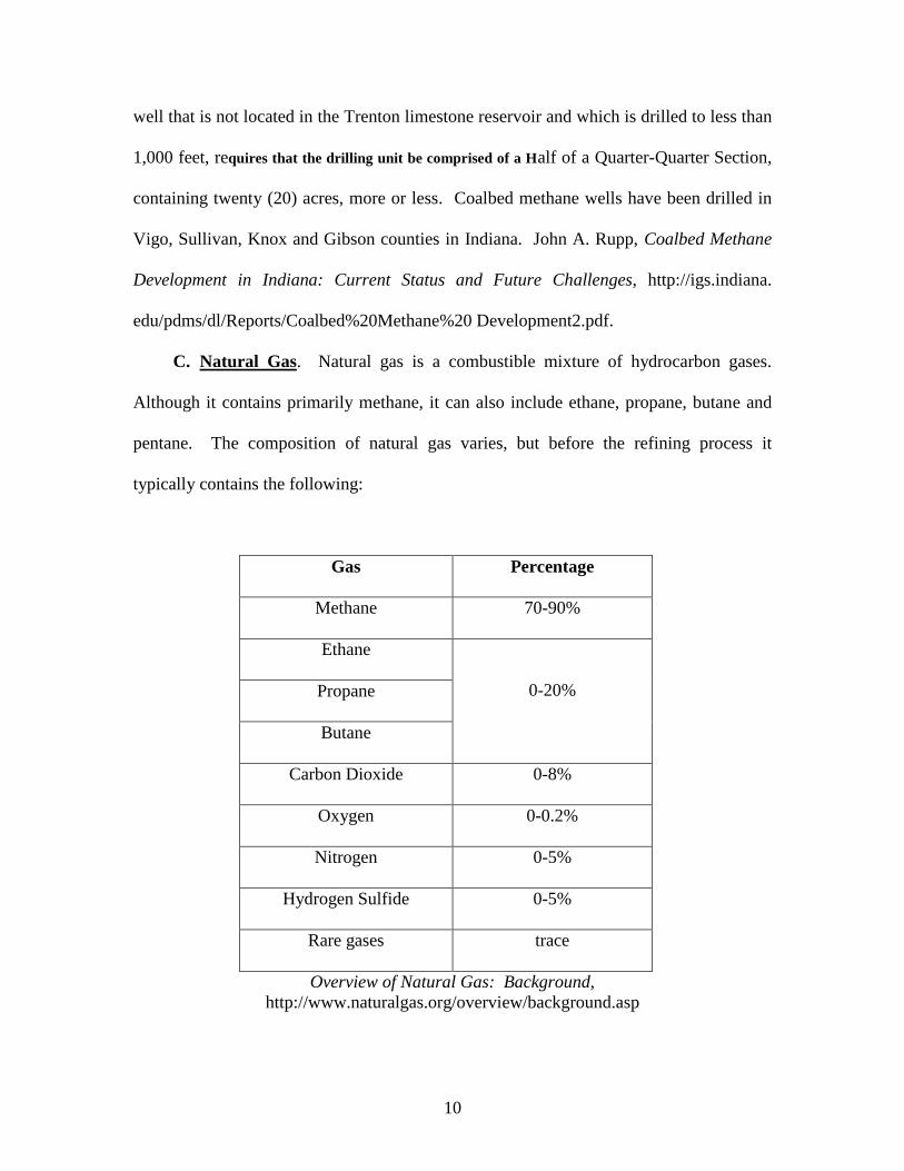
C. Natural Gas. Natural gas is a combustible mixture of hydrocarbon gases.
Although it contains primarily methane, it can also include ethane, propane, butane and
pentane. The composition of natural gas varies, but before the refining process it
typically contains the following:
Gas Percentage
Methane 70-90%
Ethane
0-20% Propane
Butane
Carbon Dioxide 0-8%
Oxygen 0-0.2%
Nitrogen 0-5%
Hydrogen Sulfide 0-5%
Rare gases trace
Overview of Natural Gas: Background,
http://www.naturalgas.org/overview/background.asp
11
The discovery of natural gas is commonly associated with oil deposits. Like other fossil
fuels, natural gas is essentially the remains of animals and microorganisms.
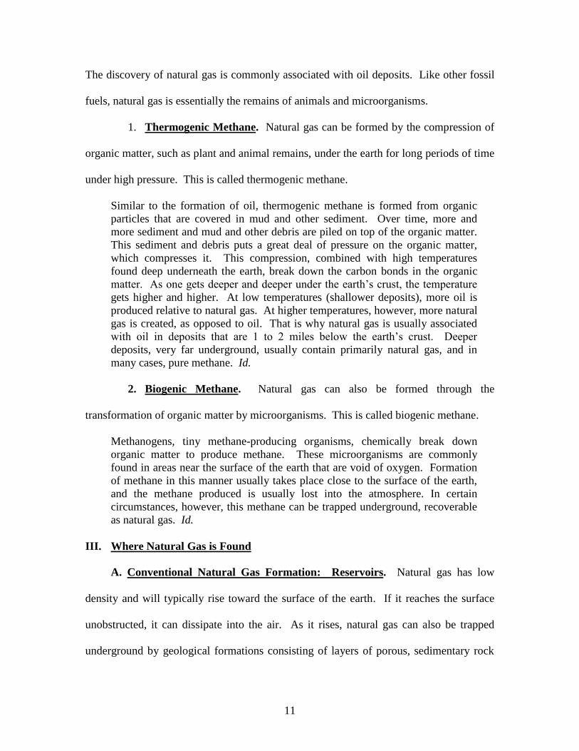
1. Thermogenic Methane. Natural gas can be formed by the compression of
organic matter, such as plant and animal remains, under the earth for long periods of time
under high pressure. This is called thermogenic methane.
Similar to the formation of oil, thermogenic methane is formed from organic
particles that are covered in mud and other sediment. Over time, more and
more sediment and mud and other debris are piled on top of the organic matter.
This sediment and debris puts a great deal of pressure on the organic matter,
which compresses it. This compression, combined with high temperatures
found deep underneath the earth, break down the carbon bonds in the organic
matter. As one gets deeper and deeper under the earth’s crust, the temperature
gets higher and higher. At low temperatures (shallower deposits), more oil is
produced relative to natural gas. At higher temperatures, however, more natural
gas is created, as opposed to oil. That is why natural gas is usually associated
with oil in deposits that are 1 to 2 miles below the earth’s crust. Deeper
deposits, very far underground, usually contain primarily natural gas, and in
many cases, pure methane. Id.
2. Biogenic Methane. Natural gas can also be formed through the
transformation of organic matter by microorganisms. This is called biogenic methane.
Methanogens, tiny methane-producing organisms, chemically break down
organic matter to produce methane. These microorganisms are commonly
found in areas near the surface of the earth that are void of oxygen. Formation
of methane in this manner usually takes place close to the surface of the earth,
and the methane produced is usually lost into the atmosphere. In certain
circumstances, however, this methane can be trapped underground, recoverable
as natural gas. Id.
III. Where Natural Gas is Found
A. Conventional Natural Gas Formation: Reservoirs. Natural gas has low
density and will typically rise toward the surface of the earth. If it reaches the surface
unobstructed, it can dissipate into the air. As it rises, natural gas can also be trapped
underground by geological formations consisting of layers of porous, sedimentary rock

12
“with a denser, impermeable layer of rock on top.” Id. Significant amounts of natural
gas can be trapped in rock formations known as reservoirs.
There are a number of different types of these formations, but the most common
is created when the impermeable sedimentary rock forms a ‘dome’ shape, like
an umbrella that catches all of the natural gas that is floating to the surface.
There are a number of ways that this sort of ‘dome’ may be formed. For
instance, faults are a common location for oil and natural gas deposits to exist.
A fault occurs when the normal sedimentary layers sort of ‘split’ vertically, so
that impermeable rock shifts down to trap natural gas in the more permeable
limestone or sandstone layers. Essentially, the geological formation which
layers impermeable rock over more porous, oil and gas rich sediment has the
potential to form a reservoir. Id.
Natural gas that is trapped in a reservoir can be recovered by drilling a hole through
the impermeable rock.
http://www.eia.doe.gov/pub/oil_gas/petroleum/analysis_publications/oil_market_basics/supply_petroleum_
trap.htm
13
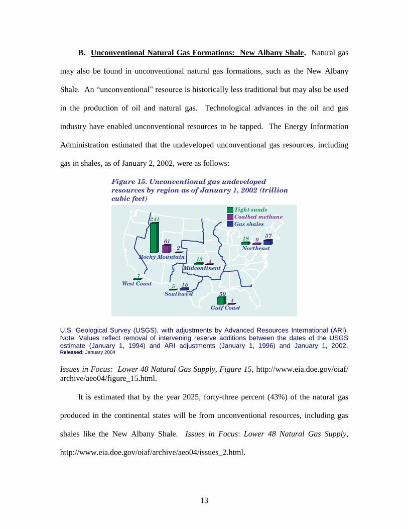
B. Unconventional Natural Gas Formations: New Albany Shale. Natural gas
may also be found in unconventional natural gas formations, such as the New Albany
Shale. An “unconventional” resource is historically less traditional but may also be used
in the production of oil and natural gas. Technological advances in the oil and gas
industry have enabled unconventional resources to be tapped. The Energy Information
Administration estimated that the undeveloped unconventional gas resources, including
gas in shales, as of January 2, 2002, were as follows:
U.S. Geological Survey (USGS), with adjustments by Advanced Resources International (ARI). Note: Values reflect removal of intervening reserve additions between the dates of the USGS estimate (January 1, 1994) and ARI adjustments (January 1, 1996) and January 1, 2002. Released: January 2004
Issues in Focus: Lower 48 Natural Gas Supply, Figure 15, http://www.eia.doe.gov/oiaf/
archive/aeo04/figure_15.html.
It is estimated that by the year 2025, forty-three percent (43%) of the natural gas
produced in the continental states will be from unconventional resources, including gas
shales like the New Albany Shale. Issues in Focus: Lower 48 Natural Gas Supply,
http://www.eia.doe.gov/oiaf/archive/aeo04/issues_2.html.

14
Advanced Resources International (ARI). Conventional: EIA computation based on onshore unconventional production
from ARI and total production from EIA, Natural Gas Annual, DOE/EIA-0131(90-02). Projections: AEO2004 National
Energy Modeling System, run AEO2004.D101703E. Released: January 2004
Issues in Focus: Lower 48 Natural Gas Supply, Figure 14, http://www.eia.doe.gov/oiaf/
archive/aeo04/figure_14.html.
IV. Description of the New Albany Shale
A. Location of the New Albany Shale. The New Albany Shale formation covers
southwestern Indiana, southeastern Illinois, and northwestern Kentucky and encompasses
approximately 60,000 square miles. New Albany Shale, Southern Indiana,http: //www.
baselineoil.com/OilGasAssets/NewAlbanyShaleSouthernIndiana/tabid/82/Default.aspx.
http://www.naturalgas.org/overview/unconvent_ng_resource.asp
Source: Gas Technology Institute
15
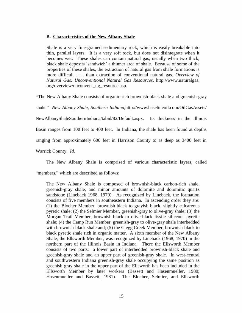
B. Characteristics of the New Albany Shale
Shale is a very fine-grained sedimentary rock, which is easily breakable into
thin, parallel layers. It is a very soft rock, but does not disintegrate when it
becomes wet. These shales can contain natural gas, usually when two thick,
black shale deposits ‘sandwich’ a thinner area of shale. Because of some of the
properties of these shales, the extraction of natural gas from shale formations is
more difficult . . . than extraction of conventional natural gas. Overview of
Natural Gas: Unconventional Natural Gas Resources, http://www.naturalgas.
org/overview/unconvent_ng_resource.asp.
“The New Albany Shale consists of organic-rich brownish-black shale and greenish-gray
shale.” New Albany Shale, Southern Indiana,http://www.baselineoil.com/OilGasAssets/
NewAlbanyShaleSouthernIndiana/tabid/82/Default.aspx. Its thickness in the Illinois
Basin ranges from 100 feet to 400 feet. In Indiana, the shale has been found at depths
ranging from approximately 600 feet in Harrison County to as deep as 3400 feet in
Warrick County. Id.
The New Albany Shale is comprised of various characteristic layers, called
“members,” which are described as follows:
The New Albany Shale is composed of brownish-black carbon-rich shale,
greenish-gray shale, and minor amounts of dolomite and dolomitic quartz
sandstone (Lineback 1968, 1970). As recognized by Lineback, the formation
consists of five members in southeastern Indiana. In ascending order they are:
(1) the Blocher Member, brownish-black to grayish-black, slightly calcareous
pyretic shale; (2) the Selmier Member, greenish-gray to olive-gray shale; (3) the
Morgan Trail Member, brownish-black to olive-black fissile siliceous pyretic
shale; (4) the Camp Run Member, greenish-gray to olive-gray shale interbedded
with brownish-black shale and; (5) the Clegg Creek Member, brownish-black to
black pyretic shale rich in organic matter. A sixth member of the New Albany
Shale, the Ellsworth Member, was recognized by Lineback (1968, 1970) in the
northern part of the Illinois Basin in Indiana. There the Ellsworth Member
consists of two parts: a lower part of interbedded brownish-black shale and
greenish-gray shale and an upper part of greenish-gray shale. In west-central
and southwestern Indiana greenish-gray shale occupying the same position as
greenish-gray shale in the upper part of the Ellsworth has been included in the
Ellsworth Member by later workers (Bassett and Hasenmueller, 1980;
Hasenmueller and Bassett, 1981). The Blocher, Selmier, and Ellsworth
16
Members have been recognized and mapped in the subsurface (Lineback, 1970;
Hasenmueller and Bassett, 1980a, 1980b; and Bassett and Hasenmueller, 1980).
The Selmier, Morgan Trail, and Camp Run Members and part of the Clegg
Creek Member are equivalent to the Blaskiston Formation of Campbell (1946).
The Sanderson Formation (which includes the Falling Run Bed as recognized
here), the Underwood and Henryville Formations, and the Jacobs Chapel of
Campbell (1946) are now included in the upper part of the Clegg Creek
Member.” New Albany Shale, Erian to Kinderhookian Series, Devonian and
Mississippian Systems, Indiana Geological Survey, http://igs.indiana.edu/
geology/structure/compendium/html/comp82hw.cfm.
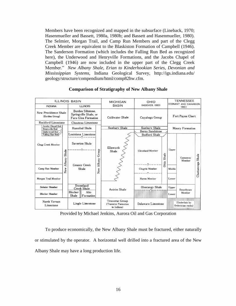
Comparison of Stratigraphy of New Albany Shale
Provided by Michael Jenkins, Aurora Oil and Gas Corporation
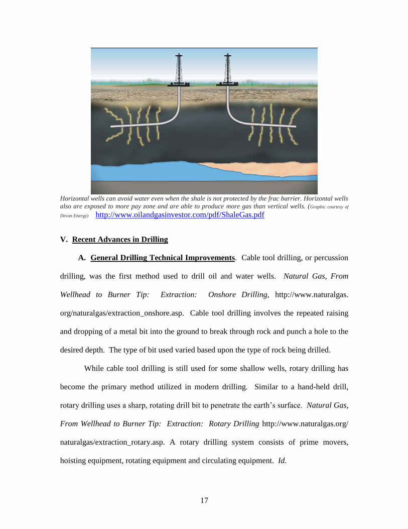
To produce economically, the New Albany Shale must be fractured, either naturally
or stimulated by the operator. A horizontal well drilled into a fractured area of the New
Albany Shale may have a long production life.
17
Horizontal wells can avoid water even when the shale is not protected by the frac barrier. Horizontal wells
also are exposed to more pay zone and are able to produce more gas than vertical wells. (Graphic courtesy of
Devon Energy) http://www.oilandgasinvestor.com/pdf/ShaleGas.pdf
V. Recent Advances in Drilling
A. General Drilling Technical Improvements. Cable tool drilling, or percussion
drilling, was the first method used to drill oil and water wells. Natural Gas, From
Wellhead to Burner Tip: Extraction: Onshore Drilling, http://www.naturalgas.
org/naturalgas/extraction_onshore.asp. Cable tool drilling involves the repeated raising
and dropping of a metal bit into the ground to break through rock and punch a hole to the
desired depth. The type of bit used varied based upon the type of rock being drilled.
While cable tool drilling is still used for some shallow wells, rotary drilling has
become the primary method utilized in modern drilling. Similar to a hand-held drill,
rotary drilling uses a sharp, rotating drill bit to penetrate the earth’s surface. Natural Gas,
From Wellhead to Burner Tip: Extraction: Rotary Drilling http://www.naturalgas.org/
naturalgas/extraction_rotary.asp. A rotary drilling system consists of prime movers,
hoisting equipment, rotating equipment and circulating equipment. Id.
18
Technological advances in exploration and extraction methods have increased
natural gas production and have made the exploration for and production of natural gas
more efficient, safe and environmentally friendly. Environment and Technology:
Natural Gas and Technology, http://www.naturalgas.org/environment/technology.asp.
Some of the recent advances in the oil and gas industry include:
●3-D and 4-D Seismic Imaging: This technology allows exploration teams to
more easily identify natural gas prospects, to place wells more effectively, to
reduce drilling costs and the number of dry holes drilled, and to cut exploration
time, leading to both economic and environmental benefits. Id.
●CO2 Sand Fracturing: This fracturing technique uses a mixture of liquid CO2
and sand propants to fracture formations to create and enlarge cracks through
which oil and gas may flow more freely. The liquid CO2 then vaporizes, leaving
only the sand in the formation to hold open the newly enlarged cracks. Thus,
there are no “leftovers” or wastes from the fracturing process that must be
removed, and the process allows for increased recovery without damaging the
deposit and while protecting groundwater resources. Id.
●Coiled Tubing: Coiled tubing allows the traditional rigid, jointed drill pipe to be
replaced with a long, flexible coiled pipe string. As a result, costs in drilling are
greatly reduced and a smaller drilling footprint may be used, meaning less impact
on the environment. Id.
●Slimhole Drilling: At least 90% of a well must be drilled with a drill bit less
than 6 inches in diameter in order to be considered slimhole drilling. (With a
conventional well, the drill bit may be as large as 12.25 inches in diameter.)
Because a slimmer hole is drilled into the ground, environmental impact is
decreased, the drilling footprint can be reduced by as much as 75%, and the size
and weight of drilling rigs can be reduced by up to 75% over traditional drilling
rigs, which reduces surface impact. Id.
Currently, it requires 22,000 fewer wells annually to develop the same amount of oil and
gas reserves as developed in 1985. Further, one well today can produce twice as much as
a single well drilled in 1985 produced. Id.
19
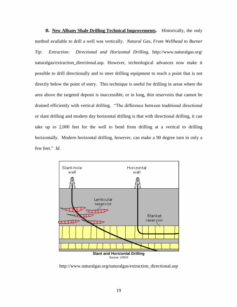
B. New Albany Shale Drilling Technical Improvements. Historically, the only
method available to drill a well was vertically. Natural Gas, From Wellhead to Burner
Tip: Extraction: Directional and Horizontal Drilling, http://www.naturalgas.org/
naturalgas/extraction_directional.asp. However, technological advances now make it
possible to drill directionally and to steer drilling equipment to reach a point that is not
directly below the point of entry. This technique is useful for drilling in areas where the
area above the targeted deposit is inaccessible, or in long, thin reservoirs that cannot be
drained efficiently with vertical drilling. “The difference between traditional directional
or slant drilling and modern day horizontal drilling is that with directional drilling, it can
take up to 2,000 feet for the well to bend from drilling at a vertical to drilling
horizontally. Modern horizontal drilling, however, can make a 90 degree turn in only a
few feet.” Id.
http://www.naturalgas.org/naturalgas/extraction_directional.asp
Slant and Horizontal Drilling
Source: USGS
20
Borehole telemetry is another advance crucial to the development of horizontal
drilling. This allows engineers and geologists to take measurements and provides
subsurface information while the well is being drilled. Further, steerable downhole motor
assemblies allow the path of the well to be controlled while it is being drilled. Natural
Gas, From Wellhead to Burner Tip: Extraction: Directional and Horizontal Drilling,
http://www.naturalgas.org/naturalgas/extraction_directional.asp.
Presently, 5% to 8% of all active onshore wells in the United States are horizontal
wells. Horizontal drilling is an invaluable technology because it can reach and extract
natural gas from formations not accessible with vertical drilling. Also, horizontal drilling
allows for more economical drilling, may increase production in fields previously thought
marginal, and has less impact on environmentally sensitive areas. Id.
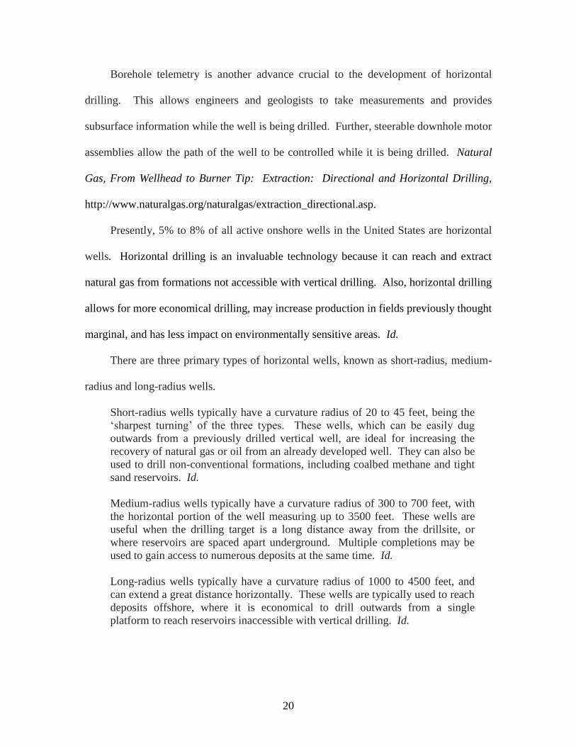
There are three primary types of horizontal wells, known as short-radius, medium-
radius and long-radius wells.
Short-radius wells typically have a curvature radius of 20 to 45 feet, being the
‘sharpest turning’ of the three types. These wells, which can be easily dug
outwards from a previously drilled vertical well, are ideal for increasing the
recovery of natural gas or oil from an already developed well. They can also be
used to drill non-conventional formations, including coalbed methane and tight
sand reservoirs. Id.
Medium-radius wells typically have a curvature radius of 300 to 700 feet, with
the horizontal portion of the well measuring up to 3500 feet. These wells are
useful when the drilling target is a long distance away from the drillsite, or
where reservoirs are spaced apart underground. Multiple completions may be
used to gain access to numerous deposits at the same time. Id.
Long-radius wells typically have a curvature radius of 1000 to 4500 feet, and
can extend a great distance horizontally. These wells are typically used to reach
deposits offshore, where it is economical to drill outwards from a single
platform to reach reservoirs inaccessible with vertical drilling. Id.
21
In spite of the above described advancements in horizontal drilling techniques, the
potential of the New Albany Shale was limited until production systems were developed
to deal with the water that is commonly commingled with the natural gas. “In the New
Albany Shale, a well commonly produces water along with the gas.” New Albany Shale
of Indiana and Kentucky, http://www.auroraogc.com/About_Aurora_Oil_and_Gas.htm.
Now with the use of horizontal drilling techniques, modern water production systems,
and low pressure gas gathering systems, production of natural gas from the New Albany
Shale is possible. Id.
New Albany Shale wells typically reach depths of 500 feet to 2,500 feet. Peak
production is reached after a 6 to 12 month dewatering period and during peak production
approximately 200,000 to 300,000 cubic feet of natural gas per day are produced. A well
in the New Albany Shale may have a productive life of approximately 30 years, with
production decreasing approximately 5% per year. Id.
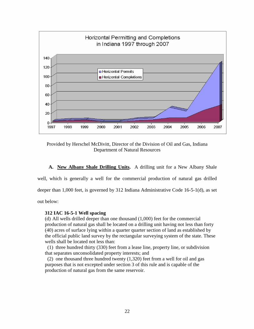
VI. Recent Increases in Horizontal Drilling.
According to Herschel McDivitt, the Director of the Division of Oil and Gas of the
Indiana Department of Natural Resources, the number of horizontal wells drilled in
Indiana has greatly increased in the last 10 years.
22
Provided by Herschel McDivitt, Director of the Division of Oil and Gas, Indiana
Department of Natural Resources
A. New Albany Shale Drilling Units. A drilling unit for a New Albany Shale
well, which is generally a well for the commercial production of natural gas drilled
deeper than 1,000 feet, is governed by 312 Indiana Administrative Code 16-5-1(d), as set
out below:
312 IAC 16-5-1 Well spacing
(d) All wells drilled deeper than one thousand (1,000) feet for the commercial
production of natural gas shall be located on a drilling unit having not less than forty
(40) acres of surface lying within a quarter quarter section of land as established by
the official public land survey by the rectangular surveying system of the state. These
wells shall be located not less than:
(1) three hundred thirty (330) feet from a lease line, property line, or subdivision
that separates unconsolidated property interests; and
(2) one thousand three hundred twenty (1,320) feet from a well for oil and gas
purposes that is not excepted under section 3 of this rule and is capable of the
production of natural gas from the same reservoir.
23
Accordingly, a drilling unit for such a New Albany Shale well shall be comprised of at
least a Quarter Section of land, containing 40 acres, more or less. Through various
processes allowed by the DNR, which shall be discussed by Herschel McDivitt of the
Indiana Department of Natural Resources, Division of Oil and Gas, operators have been
allowed to drill New Albany Shale wells on drilling units comprised of 80 acres, 160
acres, 320 acres and 640 acres, depending upon circumstances, including the well
configuration.
As noted above, the New Albany Shale has only been aggressively drilled since
1996. Various operators have stated that the New Albany Shale is not uniform in
character but in fact varies in characteristics from location to location. It is very difficult
to predict the exact nature of the shale. One generally agreed upon feature of the New
Albany Shale is that the fracturing systems runs predominantly east to west. The use of
horizontal well bores is particularly well suited for the New Albany Shale. The greater
the length of the wellbore, the greater are the chances that it will intersect a significant
fracture or a significant number of smaller fractures to allow natural gas to flow to the
wellbore. The cost of drilling a well also is not greatly increased in correlation with an
increased length. In fact, it is economical to extend the wellbore as far as practical and
allowed by regulations.
B. Multilateral wells. Multilateral wells are a subcategory of horizontal wells.
Technological advances allow operators to drill multiple lateral legs from one surface
location. Permits on file with the Indiana Department of Natural Resources, Division of
Oil and Gas, reflect that operators have been granted flexibility to drill a variety of
multilateral configurations. Various operators have advised the author that they are

24
experimenting to determine what configuration is proving to be most productive and
economically feasible. As a multilateral well configuration typically covers a
considerable amount of acreage, the associated drilling units have been larger and like
New Albany Shale horizontal wells, have been approved on drilling units larger than 40
acres.
C. Forced Pooling. The use of drilling units of increased size increases the
potential for unleased acreage within a drilling unit. It is a statistical axiom that it is more
difficult for an operator to have larger blocks of land completely under lease. According
to Indiana rules and regulations, the Indiana Department of Natural Resources, Division
of Oil and Gas, will issue a permit to drill a producing well only if 100% of the land in
the drilling unit is under lease to the operator, or the operator has filed a Petition for the
Integration of Interests, an informal hearing is held, and the operator acquires an Order to
Integrate Interests from the Department of Natural Resources. Conversely, fewer New
Albany Shale wells must be drilled to drain the resources and fewer landowners have a
well site on their property.
D. Use of Voluntary Pooled Units. While the land in a drilling unit must be
leased in its entirety to the operator, land included in a voluntary pooled unit has no
corresponding requirement. The operator is most often granted by the terms of the
operative Oil and Gas Leases the right to create larger voluntary units. The purpose of
such a unit is to group, or unitize, numerous landowners and often more than one drilling
unit into a larger pooled unit. Each of the leased landowners therein agrees to accept the
payment of production proceeds based upon the ratio of the acreage they own to the
acreage contained in the entire voluntary pooled unit. If a party owns land in the
25
voluntary pooled unit that is not in a drilling unit and has not leased to the operator, the
operator is not required to force pool the unleased acreage. Said landowner can decline
to receive production proceeds.
The landowners who participate in a voluntary pooled unit exchange for a reduction
in the ratio upon which they receive payment, an increased chance that production will
ensue. For example, if no voluntary pooled unit is in place and a landowner owns 80
acres that comprise a drilling unit in totality, said party will receive 100% of the royalty
interest on production proceeds from one well. However, if said landowner participates
in a voluntary pooled unit containing 640 acres, the landowner will receive only 1/8 of
the royalty interest paid but production proceeds will be generated from the full 640
acres, which may contain many producing wells. In essence, the landowner can receive
income not only from the well on his or her property but from wells in the general area
that are included in the voluntary pooled unit. If the well on a particular landowner’s
acreage is not productive, they can still receive royalty payments of production proceeds
if other wells in the voluntary pooled unit are productive.
VII. What a Drill Site Looks Like
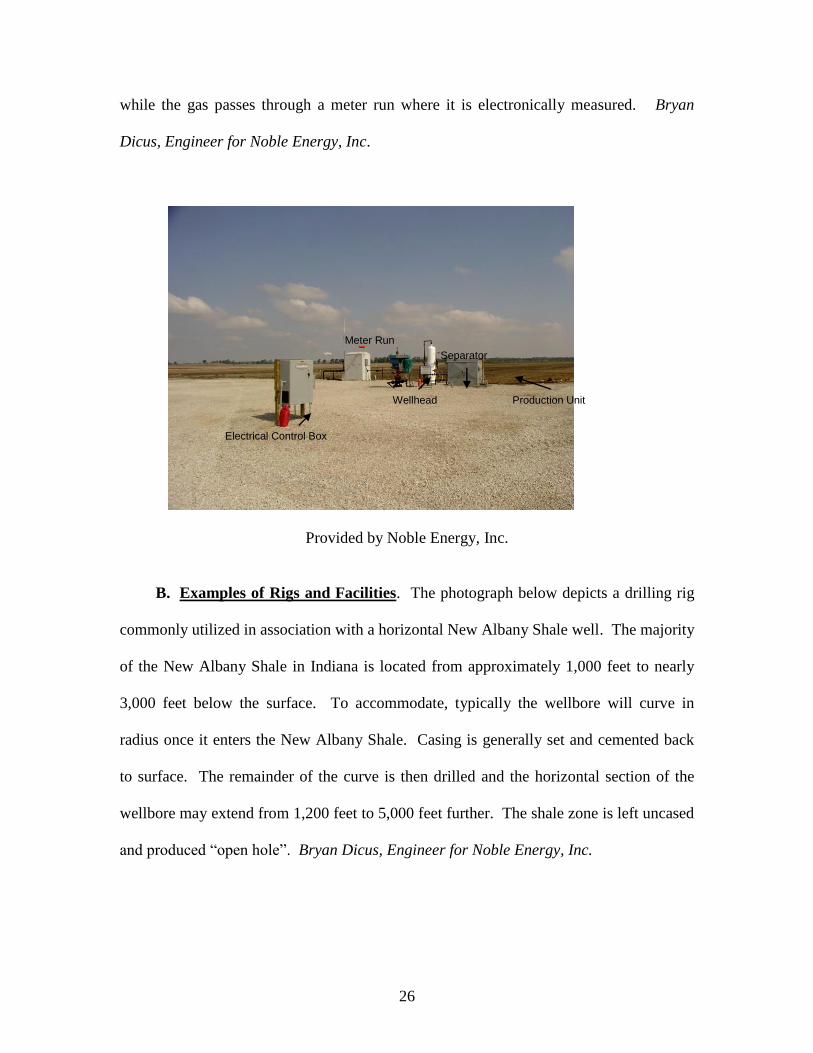
A. Impact of Operations on the Surface. The photograph below depicts a
common New Albany Shale drilling site utilizing a progressive cavity lift system. A
New Albany Shale well must produce water along with the gas. The volume of water
typically produced ranges from less then 100 barrels of water per day to over 1,000
barrels of water per day. Both the casing and tubing fluids pass through the separator
where the free water is removed from the gas stream. The water is sent to a disposal site,
26
while the gas passes through a meter run where it is electronically measured. Bryan
Dicus, Engineer for Noble Energy, Inc.
Provided by Noble Energy, Inc.
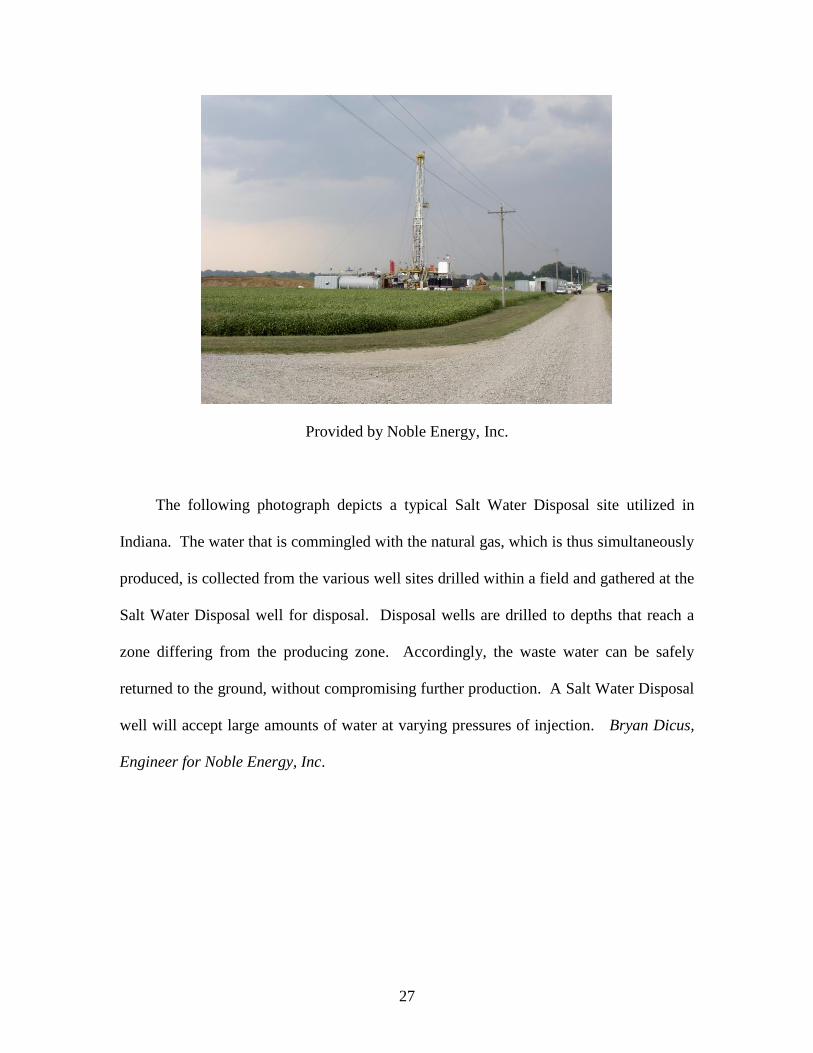
B. Examples of Rigs and Facilities. The photograph below depicts a drilling rig
commonly utilized in association with a horizontal New Albany Shale well. The majority
of the New Albany Shale in Indiana is located from approximately 1,000 feet to nearly
3,000 feet below the surface. To accommodate, typically the wellbore will curve in
radius once it enters the New Albany Shale. Casing is generally set and cemented back
to surface. The remainder of the curve is then drilled and the horizontal section of the
wellbore may extend from 1,200 feet to 5,000 feet further. The shale zone is left uncased
and produced “open hole”. Bryan Dicus, Engineer for Noble Energy, Inc.
Electrical Control Box
Wellhead
Meter Run
Separator
Production Unit
27
Provided by Noble Energy, Inc.
The following photograph depicts a typical Salt Water Disposal site utilized in
Indiana. The water that is commingled with the natural gas, which is thus simultaneously
produced, is collected from the various well sites drilled within a field and gathered at the
Salt Water Disposal well for disposal. Disposal wells are drilled to depths that reach a
zone differing from the producing zone. Accordingly, the waste water can be safely
returned to the ground, without compromising further production. A Salt Water Disposal
well will accept large amounts of water at varying pressures of injection. Bryan Dicus,
Engineer for Noble Energy, Inc.

28
Salt Water Disposal Site
Provided by Noble Energy, Inc.
VIII. Preparing Natural Gas for Sale
Once natural gas is brought up to the wellhead, it must be processed and transported
to the consumer for use.
http://www.eia.doe.gov/kids/energyfacts/sources/non-
renewable/naturalgas.html#HOWWEGETIT.
Storage Tanks
Injection Pump
Containment
29
A. Natural Gas Processing. Natural gas must be processed before it can be used
by consumers. It is necessary to remove various hydrocarbons and fluids from the pure
natural gas to produce what is known as “pipeline quality” dry natural gas. Natural Gas,
From Wellhead to Burner Tip: Production: Processing Natural Gas, http://www.
naturalgas.org/naturalgas/processing_ng.asp. However, not all the hydrocarbons that are
removed are considered waste products. Hydrocarbons such as ethane, propane and
butane are valuable by-products of natural gas processing, can be sold separately, and
have a variety of uses. Some processing occurs at or near the wellhead while other
processing takes place at processing plants. Id. There are four main steps to processing
natural gas:
●Oil and Condensate Removal: Natural gas must be separated from the oil in
which it is dissolved; this most typically occurs at or near the wellhead. Id.
●Water Removal: It is also necessary to remove most of the associated water.
This separation typically occurs at or near the wellhead. Id.
●Separation of Natural Gas Liquids: Natural gas liquids such as ethane, propane,
and butane are commonly removed because they have a higher value as separate
products. Typically, natural gas liquids are removed at a centralized processing
plant. Id.
●Sulfur and Carbon Dioxide Removal: Removing sulfur and carbon dioxide is
one of the most important parts of gas processing. Removing the sulfur is
commonly referred to as “sweetening” the gas because gas is considered “sour” if
the sulfur exceeds 5.7 milligrams of sulfur per cubic meter of natural gas. This
process occurs at a gas processing plant. Id.
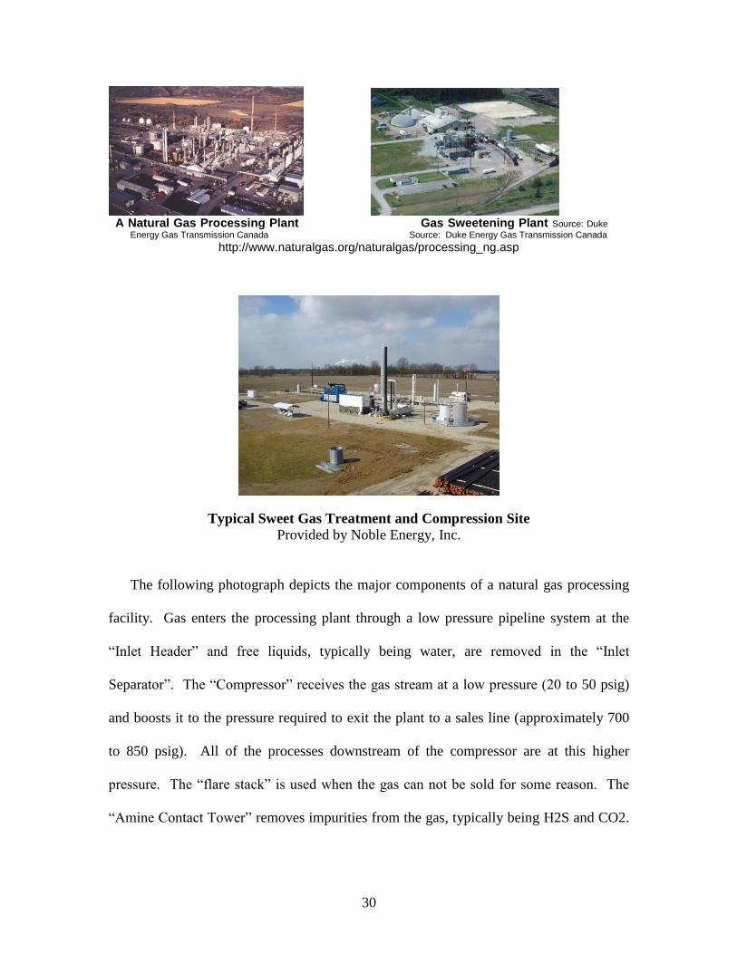
The photographs below depict various processing plants. Most modern processing
facilities are completely electronically controlled and monitored. Bryan Dicus, Engineer
for Noble Energy, Inc.
30
A Natural Gas Processing Plant Gas Sweetening Plant Source: Duke
Energy Gas Transmission Canada Source: Duke Energy Gas Transmission Canada
http://www.naturalgas.org/naturalgas/processing_ng.asp
Typical Sweet Gas Treatment and Compression Site
Provided by Noble Energy, Inc.
The following photograph depicts the major components of a natural gas processing
facility. Gas enters the processing plant through a low pressure pipeline system at the
“Inlet Header” and free liquids, typically being water, are removed in the “Inlet
Separator”. The “Compressor” receives the gas stream at a low pressure (20 to 50 psig)
and boosts it to the pressure required to exit the plant to a sales line (approximately 700
to 850 psig). All of the processes downstream of the compressor are at this higher
pressure. The “flare stack” is used when the gas can not be sold for some reason. The
“Amine Contact Tower” removes impurities from the gas, typically being H2S and CO2.
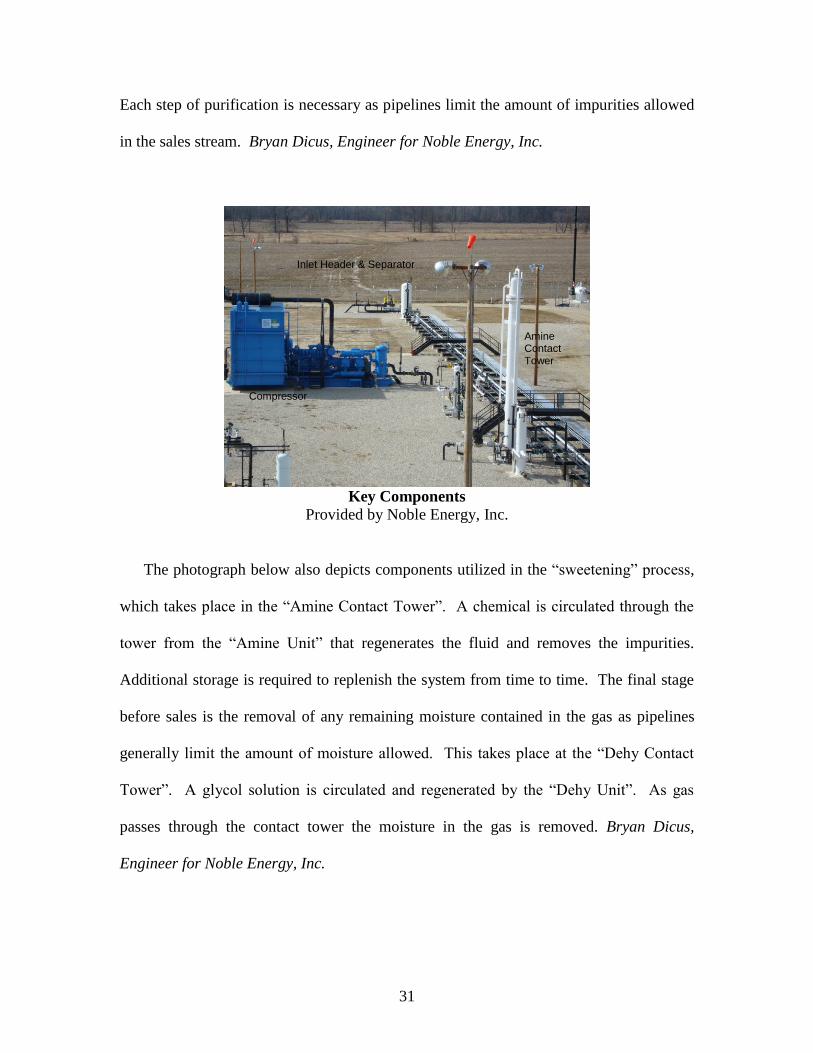
31
Each step of purification is necessary as pipelines limit the amount of impurities allowed
in the sales stream. Bryan Dicus, Engineer for Noble Energy, Inc.
Key Components
Provided by Noble Energy, Inc.
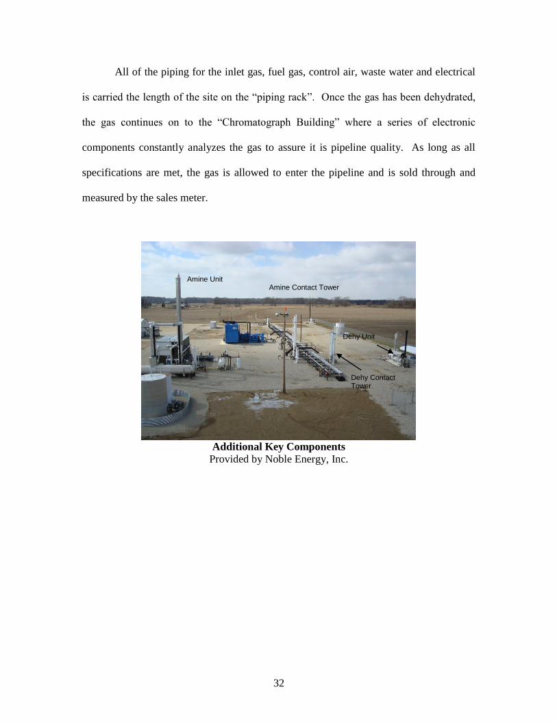
The photograph below also depicts components utilized in the “sweetening” process,
which takes place in the “Amine Contact Tower”. A chemical is circulated through the
tower from the “Amine Unit” that regenerates the fluid and removes the impurities.
Additional storage is required to replenish the system from time to time. The final stage
before sales is the removal of any remaining moisture contained in the gas as pipelines
generally limit the amount of moisture allowed. This takes place at the “Dehy Contact
Tower”. A glycol solution is circulated and regenerated by the “Dehy Unit”. As gas
passes through the contact tower the moisture in the gas is removed. Bryan Dicus,
Engineer for Noble Energy, Inc.
Amine Contact Tower
Inlet Header & Separator
Compressor
32
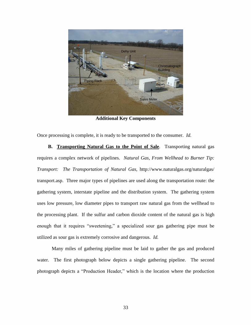
All of the piping for the inlet gas, fuel gas, control air, waste water and electrical
is carried the length of the site on the “piping rack”. Once the gas has been dehydrated,
the gas continues on to the “Chromatograph Building” where a series of electronic
components constantly analyzes the gas to assure it is pipeline quality. As long as all
specifications are met, the gas is allowed to enter the pipeline and is sold through and
measured by the sales meter.
Additional Key Components
Provided by Noble Energy, Inc.
Amine Unit Amine Contact Tower
Dehy Unit
Dehy Contact Tower
33
Additional Key Components
Once processing is complete, it is ready to be transported to the consumer. Id.
B. Transporting Natural Gas to the Point of Sale. Transporting natural gas
requires a complex network of pipelines. Natural Gas, From Wellhead to Burner Tip:
Transport: The Transportation of Natural Gas, http://www.naturalgas.org/naturalgas/
transport.asp. Three major types of pipelines are used along the transportation route: the
gathering system, interstate pipeline and the distribution system. The gathering system
uses low pressure, low diameter pipes to transport raw natural gas from the wellhead to
the processing plant. If the sulfur and carbon dioxide content of the natural gas is high
enough that it requires “sweetening,” a specialized sour gas gathering pipe must be
utilized as sour gas is extremely corrosive and dangerous. Id.
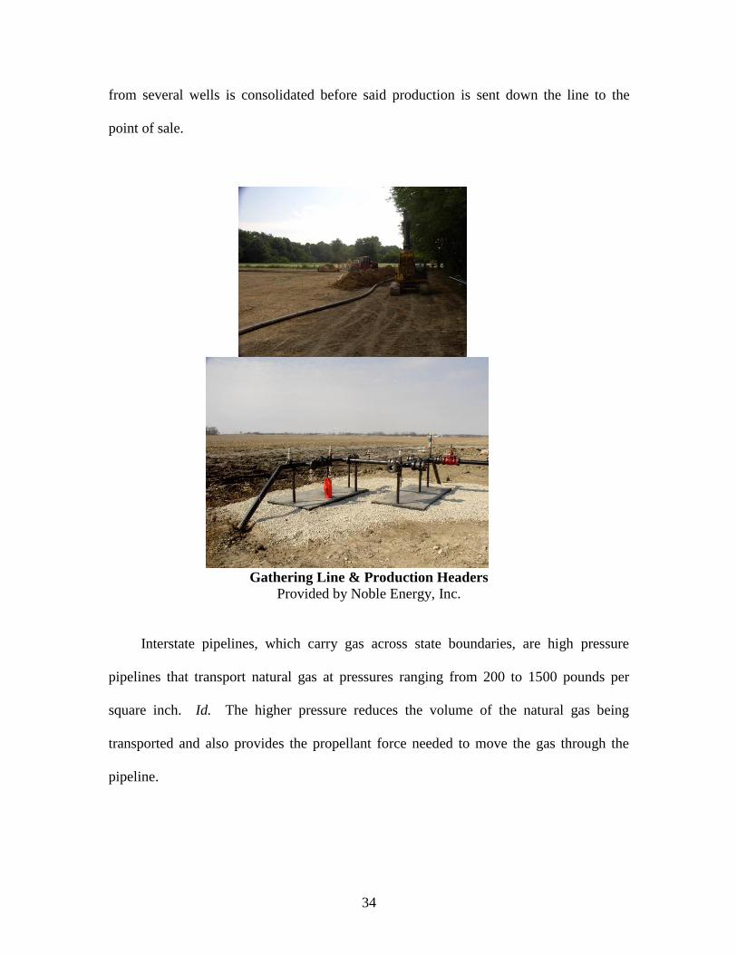
Many miles of gathering pipeline must be laid to gather the gas and produced
water. The first photograph below depicts a single gathering pipeline. The second
photograph depicts a “Production Header,” which is the location where the production
Sales Meter
Chromatograph Building
Dehy Unit
Piping Rack
34
from several wells is consolidated before said production is sent down the line to the
point of sale.
Gathering Line & Production Headers
Provided by Noble Energy, Inc.
Interstate pipelines, which carry gas across state boundaries, are high pressure
pipelines that transport natural gas at pressures ranging from 200 to 1500 pounds per
square inch. Id. The higher pressure reduces the volume of the natural gas being
transported and also provides the propellant force needed to move the gas through the
pipeline.
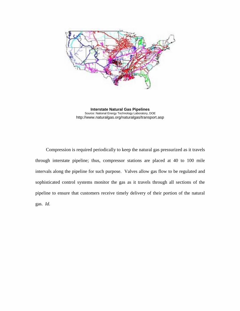
Compression is required periodically to keep the natural gas pressurized as it travels
through interstate pipeline; thus, compressor stations are placed at 40 to 100 mile
intervals along the pipeline for such purpose. Valves allow gas flow to be regulated and
sophisticated control systems monitor the gas as it travels through all sections of the
pipeline to ensure that customers receive timely delivery of their portion of the natural
gas. Id.
Interstate Natural Gas Pipelines Source: National Energy Technology Laboratory, DOE
http://www.naturalgas.org/naturalgas/transport.asp

36
Interstate Gas Pipeline
http://www.naturalgas.org/images/interstate_pipeline.jpg
Distribution is the final step in delivering natural gas to the consumer. Natural Gas,
From Wellhead to Burner Tip: Distribution: Natural Gas Distribution, http://www.
naturalgas.org/naturalgas/distribution.asp. While some large industrial and commercial
consumers receive natural gas directly from interstate pipelines, most consumers receive
natural gas from local distribution companies, typically owned by investors or local
governments. Local distribution companies transport the natural gas to consumers from
delivery points along interstate pipelines through thousands of miles of small-diameter
distribution pipe. “It has been estimated that there exists over one million miles of
distribution pipe in the United States.” Id.

37
IX. Conclusion
The oil and gas industry is advancing rapidly. Effective and increased drilling activity in
the state of Indiana brings economic development on the county, state and national level.