oil fired furnace and induction furnace: a review - ijser · oil fired furnace and induction...
TRANSCRIPT
International Journal of Scientific & Engineering Research, Volume 6, Issue 8, August-2015ISSN 2229-5518
IJSER © 2015http://www.ijser.org
Oil Fired Furnace and InductionFurnace: A Review
Bhaskar Dhiman, O.S. Bhatia
Abstract— Heat treatment is the linked process for treatment of machined and forging components. Furnaces can be used for heattreatment process. We have observed that the major problems in oil-fired furnace are non-uniform flame distribution, oxidation of metal,scale formation, carbon loss of metals and emission of pollutants. Oil fired furnaces have low productivity and long start-up time. To avoidthese problems the new technology induction furnace should be used. By using the induction furnace instead of oil fired furnace theproductivity may be increased and production cost may be reduced. So it is necessary to design, optimize and install the inductionfurnaces over the oil fired furnaces. This paper presents the reviews on latest trends and developments available in the area of furnaces sothat the total equipment cost and losses can be minimized.
Index Terms— Design, Electromagnetic Induction, Furnace, Induction Furnace, Joule Effect, Oil Fired Furnace, Productivity.
—————————— ——————————
1 INTRODUCTIONfurnace is an equipment used to melt metals for castingor to heat materials to change their shape (e.g. forging,rolling) or properties (heat treatment) [45], [52], [49].
Since exhaust gases from the fuel comes in contact with thesurface of materials. Then type of fuel used is important be-cause some materials will not tolerate sulphur in the fuel. Sol-id fuels generate particulate matter, which will interfere thematerials placed inside the furnace. For this reason most fur-naces use liquid fuel, gaseous fuel or electricity as energy in-put. Melting furnaces for nonferrous materials use fuel oil.Furnace ideally should heat as much of material as possible toa uniform temperature with the least possible fuel and la-bour.The key to efficient furnace operation lies in completecombustion of fuel with minimum excess air. Furnaces operatewith relatively low efficiencies (as low as 7%) compared toother combustion equipment such as the boiler (with efficien-cies higher than 90%). This is caused by the high operatingtemperatures in the furnace. For example, a furnace heatingmaterials to 1200 °C will emit exhaust gases at 1200 °C ormore, which results insignificant heat losses through thechimney. Steel is a part of our everyday life, in both the developedand developing world [50]. Now-a-days demand of steel isincreasing due to increase in infrastructure and globalization.Natural gas fired furnaces have installation cost advantageand induction furnaces have the advantage of less scale for-mation on the surface of the work. In present world customersare more conscious about the quality of steel mean slower lev-els of residuals such as sulphur, phosphorus, oxygen, hydro-gen, nitrogen and tramp elements. The quality steels are mostefficiently produced in electric furnaces (EAF / IF), becausethey have proved its worthiness in production of a wide varie-ty of special alloy steels having controlled chemistry and be
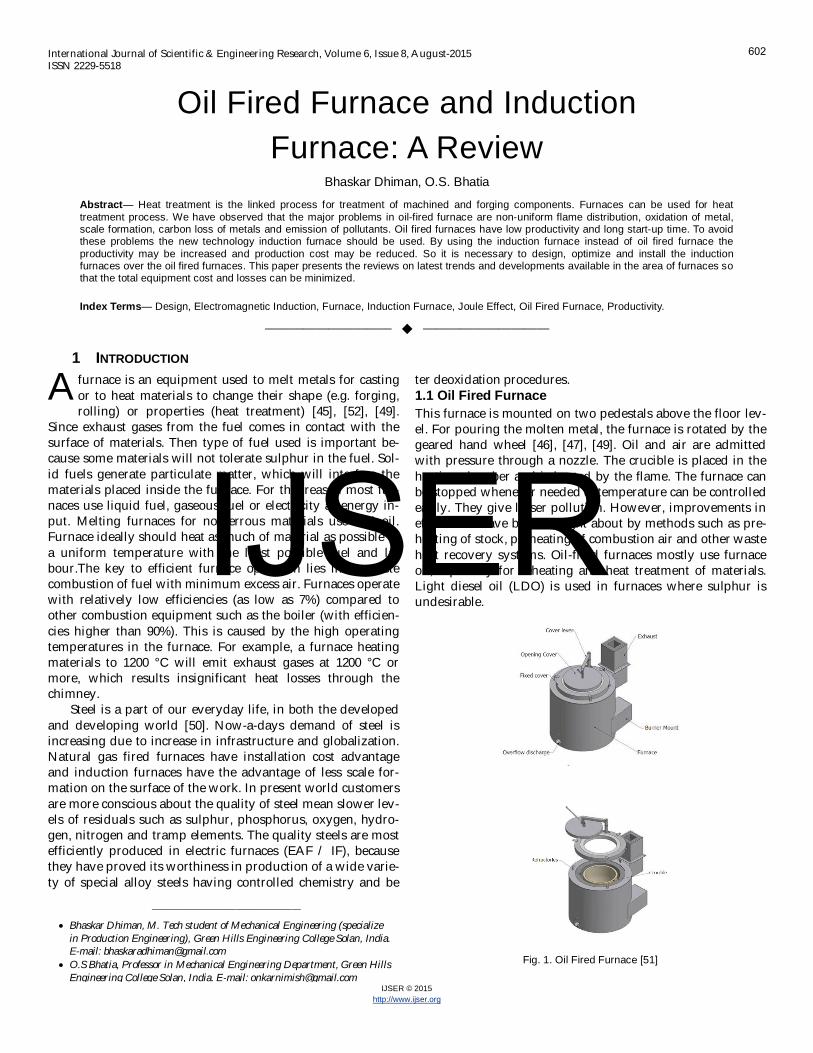
ter deoxidation procedures.1.1 Oil Fired FurnaceThis furnace is mounted on two pedestals above the floor lev-el. For pouring the molten metal, the furnace is rotated by thegeared hand wheel [46], [47], [49]. Oil and air are admittedwith pressure through a nozzle. The crucible is placed in theheating chamber and is heated by the flame. The furnace canbe stopped whenever needed & temperature can be controlledeasily. They give lesser pollution. However, improvements inefficiencies have been brought about by methods such as pre-heating of stock, preheating of combustion air and other wasteheat recovery systems. Oil-fired furnaces mostly use furnaceoil, especially for reheating and heat treatment of materials.Light diesel oil (LDO) is used in furnaces where sulphur isundesirable.
Fig. 1. Oil Fired Furnace [51]
A
————————————————
Bhaskar Dhiman, M. Tech student of Mechanical Engineering (specializein Production Engineering), Green Hills Engineering College Solan, India.E-mail: [email protected] Bhatia, Professor in Mechanical Engineering Department, Green HillsEngineering College Solan, India. E-mail: [email protected]
602
IJSER
International Journal of Scientific & Engineering Research, Volume 6, Issue 8, August-2015ISSN 2229-5518
IJSER © 2015http://www.ijser.org
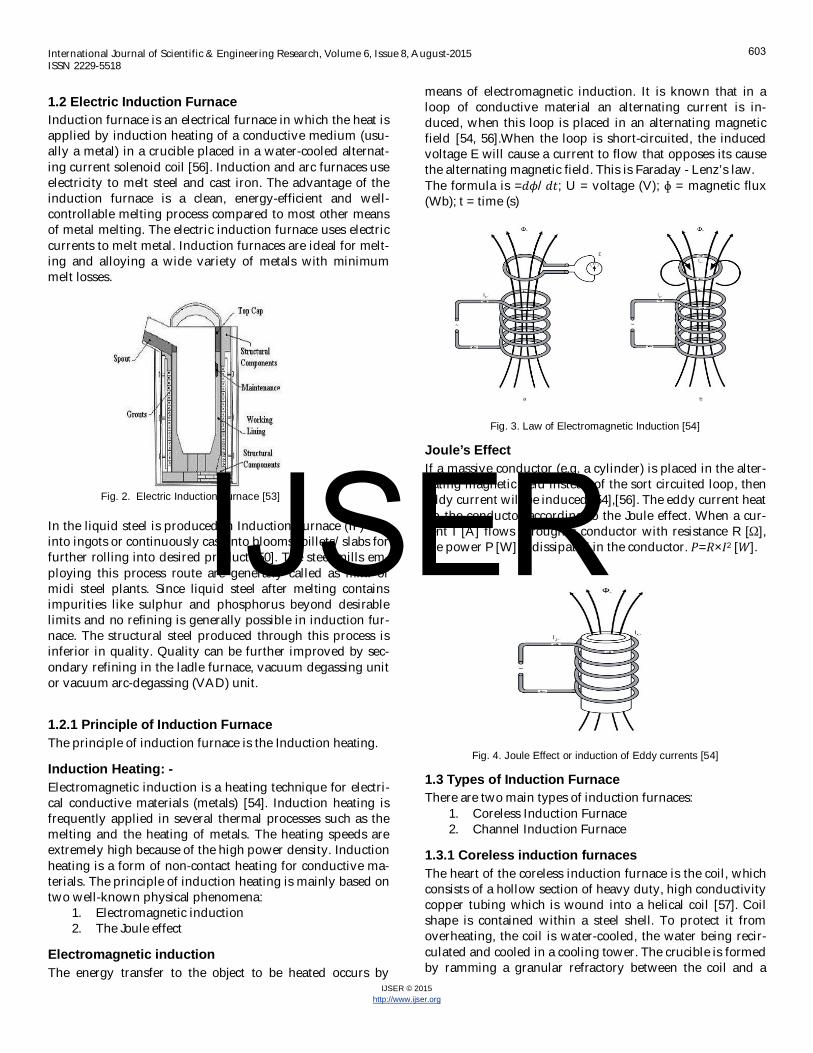
1.2 Electric Induction FurnaceInduction furnace is an electrical furnace in which the heat isapplied by induction heating of a conductive medium (usu-ally a metal) in a crucible placed in a water-cooled alternat-ing current solenoid coil [56]. Induction and arc furnaces useelectricity to melt steel and cast iron. The advantage of theinduction furnace is a clean, energy-efficient and well-controllable melting process compared to most other meansof metal melting. The electric induction furnace uses electriccurrents to melt metal. Induction furnaces are ideal for melt-ing and alloying a wide variety of metals with minimummelt losses.
Fig. 2. Electric Induction Furnace [53]
In the liquid steel is produced in Induction Furnace (IF) castinto ingots or continuously cast into blooms/billets/slabs forfurther rolling into desired product [50]. The steel mills em-ploying this process route are generally called as mini ormidi steel plants. Since liquid steel after melting containsimpurities like sulphur and phosphorus beyond desirablelimits and no refining is generally possible in induction fur-nace. The structural steel produced through this process isinferior in quality. Quality can be further improved by sec-ondary refining in the ladle furnace, vacuum degassing unitor vacuum arc-degassing (VAD) unit.
1.2.1 Principle of Induction FurnaceThe principle of induction furnace is the Induction heating.
Induction Heating: -Electromagnetic induction is a heating technique for electri-cal conductive materials (metals) [54]. Induction heating isfrequently applied in several thermal processes such as themelting and the heating of metals. The heating speeds areextremely high because of the high power density. Inductionheating is a form of non-contact heating for conductive ma-terials. The principle of induction heating is mainly based ontwo well-known physical phenomena:
1. Electromagnetic induction2. The Joule effect
Electromagnetic inductionThe energy transfer to the object to be heated occurs by
means of electromagnetic induction. It is known that in aloop of conductive material an alternating current is in-duced, when this loop is placed in an alternating magneticfield [54, 56].When the loop is short-circuited, the inducedvoltage E will cause a current to flow that opposes its causethe alternating magnetic field. This is Faraday - Lenz’s law.The formula is = / ; U = voltage (V); = magnetic flux(Wb); t = time (s)
Fig. 3. Law of Electromagnetic Induction [54]
Joule’s EffectIf a massive conductor (e.g. a cylinder) is placed in the alter-nating magnetic field instead of the sort circuited loop, theneddy current will be induced [54],[56]. The eddy current heatup the conductor according to the Joule effect. When a cur-rent I [A] flows through a conductor with resistance R [ ],the power P [W] is dissipated in the conductor. = × 2 [ ].
Fig. 4. Joule Effect or induction of Eddy currents [54]
1.3 Types of Induction FurnaceThere are two main types of induction furnaces:
1. Coreless Induction Furnace2. Channel Induction Furnace
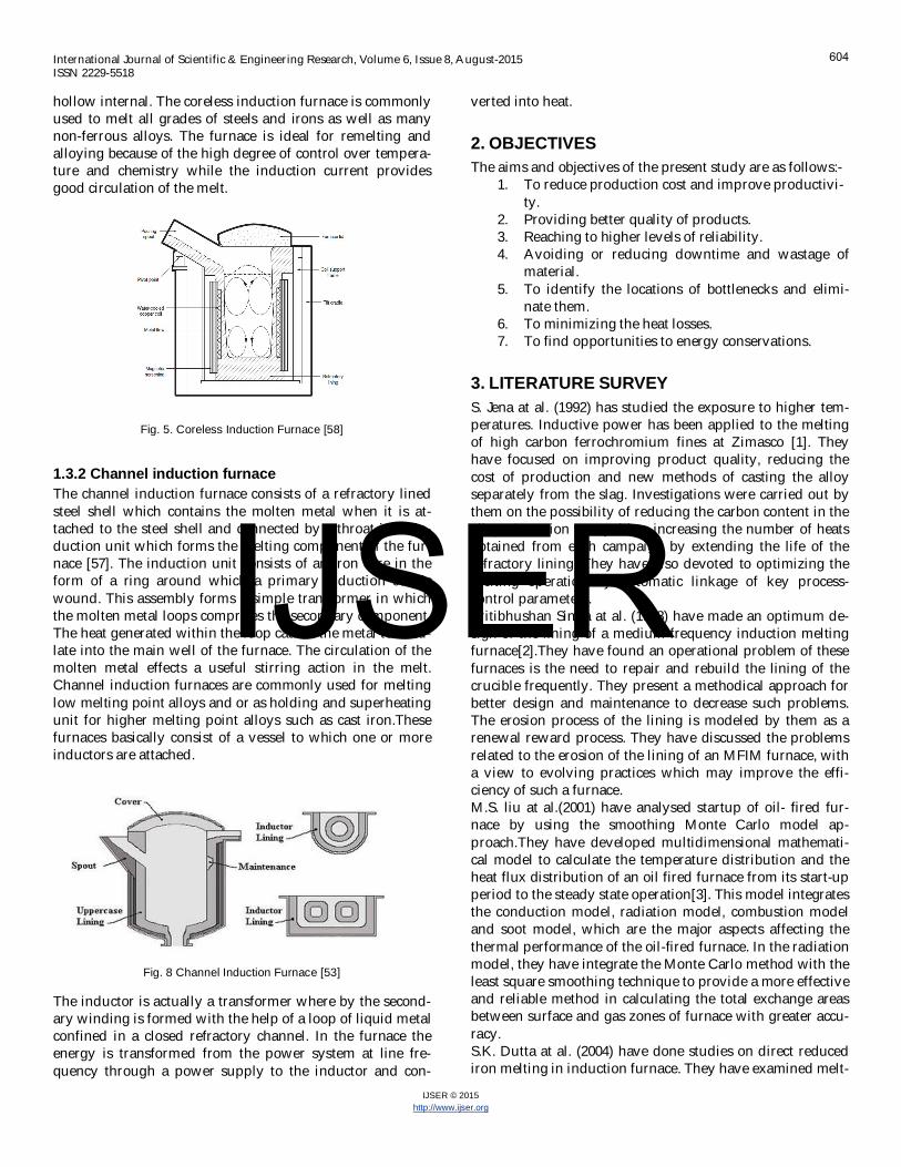
1.3.1 Coreless induction furnacesThe heart of the coreless induction furnace is the coil, whichconsists of a hollow section of heavy duty, high conductivitycopper tubing which is wound into a helical coil [57]. Coilshape is contained within a steel shell. To protect it fromoverheating, the coil is water-cooled, the water being recir-culated and cooled in a cooling tower. The crucible is formedby ramming a granular refractory between the coil and a
603
IJSER
International Journal of Scientific & Engineering Research, Volume 6, Issue 8, August-2015ISSN 2229-5518
IJSER © 2015http://www.ijser.org
hollow internal. The coreless induction furnace is commonlyused to melt all grades of steels and irons as well as manynon-ferrous alloys. The furnace is ideal for remelting andalloying because of the high degree of control over tempera-ture and chemistry while the induction current providesgood circulation of the melt.
Fig. 5. Coreless Induction Furnace [58]
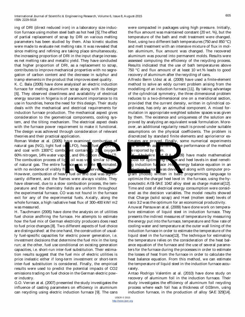
1.3.2 Channel induction furnaceThe channel induction furnace consists of a refractory linedsteel shell which contains the molten metal when it is at-tached to the steel shell and connected by a throat is an in-duction unit which forms the melting component of the fur-nace [57]. The induction unit consists of an iron core in theform of a ring around which a primary induction coil iswound. This assembly forms a simple transformer in whichthe molten metal loops comprises the secondary component.The heat generated within the loop causes the metal to circu-late into the main well of the furnace. The circulation of themolten metal effects a useful stirring action in the melt.Channel induction furnaces are commonly used for meltinglow melting point alloys and or as holding and superheatingunit for higher melting point alloys such as cast iron.Thesefurnaces basically consist of a vessel to which one or moreinductors are attached.
Fig. 8 Channel Induction Furnace [53]
The inductor is actually a transformer where by the second-ary winding is formed with the help of a loop of liquid metalconfined in a closed refractory channel. In the furnace theenergy is transformed from the power system at line fre-quency through a power supply to the inductor and con-
verted into heat.
2. OBJECTIVESThe aims and objectives of the present study are as follows:-
1. To reduce production cost and improve productivi-ty.
2. Providing better quality of products.3. Reaching to higher levels of reliability.4. Avoiding or reducing downtime and wastage of
material.5. To identify the locations of bottlenecks and elimi-
nate them.6. To minimizing the heat losses.7. To find opportunities to energy conservations.
3. LITERATURE SURVEYS. Jena at al. (1992) has studied the exposure to higher tem-peratures. Inductive power has been applied to the meltingof high carbon ferrochromium fines at Zimasco [1]. Theyhave focused on improving product quality, reducing thecost of production and new methods of casting the alloyseparately from the slag. Investigations were carried out bythem on the possibility of reducing the carbon content in thealloy. Attention was paid to increasing the number of heatsobtained from each campaign by extending the life of therefractory lining. They have also devoted to optimizing themelting operation by automatic linkage of key process-control parameters.Pritibhushan Sinha at al. (1998) have made an optimum de-sign of the lining of a medium frequency induction meltingfurnace[2].They have found an operational problem of thesefurnaces is the need to repair and rebuild the lining of thecrucible frequently. They present a methodical approach forbetter design and maintenance to decrease such problems.The erosion process of the lining is modeled by them as arenewal reward process. They have discussed the problemsrelated to the erosion of the lining of an MFIM furnace, witha view to evolving practices which may improve the effi-ciency of such a furnace.M.S. liu at al.(2001) have analysed startup of oil- fired fur-nace by using the smoothing Monte Carlo model ap-proach.They have developed multidimensional mathemati-cal model to calculate the temperature distribution and theheat flux distribution of an oil fired furnace from its start-upperiod to the steady state operation[3]. This model integratesthe conduction model, radiation model, combustion modeland soot model, which are the major aspects affecting thethermal performance of the oil-fired furnace. In the radiationmodel, they have integrate the Monte Carlo method with theleast square smoothing technique to provide a more effectiveand reliable method in calculating the total exchange areasbetween surface and gas zones of furnace with greater accu-racy.S.K. Dutta at al. (2004) have done studies on direct reducediron melting in induction furnace. They have examined melt-
604
IJSER
International Journal of Scientific & Engineering Research, Volume 6, Issue 8, August-2015ISSN 2229-5518
IJSER © 2015http://www.ijser.org
ing of DRI (direct reduced iron) in a laboratory size induc-tion furnace using molten steel bath as hot heel [5].The effectof partial replacement of scrap by DRI on various meltingparameters has been studied by them. Also kinetic studieswere made to evaluate net melting rate. It was revealed thatsince melting and refining are taking place simultaneously,the increasing proportion of DRI in the input charge increas-es net melting rate and metallic yield. They have concludedthat higher proportion of DRI, as a replacement to scrap,contributes to improve mechanical properties with no segre-gation of carbon content and the decrease in sulphur andtramp elements in the product that improves steel quality.K. C. Bala (2005) have done analysisof an electric inductionfurnace for melting aluminium scrap along with its design[6]. They observed cleanliness and availability of electricalenergy sources in Nigeria is of paramount importance to itsuse in foundries, hence the need for this design. Their studydeals with the mechanical and electrical requirements forinduction furnace production. The mechanical aspect givesconsideration to the geometrical components, cooling sys-tem, and the tilting mechanism. The electrical aspect dealswith the furnace power requirement to make it functional.The design was achieved through consideration of relevanttheories and their practical application.Roman Weber at al. (2005) have examined combustion ofnatural gas (NG), light fuel oil (LFO), heavy fuel oil (HFO),and coal with 1300°C comburent containing 20% oxygen,60% nitrogen, 14% water vapour, and 6% carbon dioxide [7].The combustion process of light oil was very similar to thatof natural gas. The entire furnace was visible illuminated,with no evidence of visibly flames being observed by them.However, combustion of heavy fuel oil and coal was signifi-cantly different, and the flames were always visible. Theyhave observed, due to a slow combustion process, the tem-perature and the chemistry fields are uniform throughoutthe experimental furnace. CO was not found in the furnaceexit for any of the experimental fuels. Axially, along thewhole furnace, a high radiative heat flux of 300–400 kW/m2was measured.H. Tauchmann (2005) have done the analysis on of utilitiesfuel choice andfiring the furnace. He attempts to estimatehow the fuel mix of German electricity producers does reactto fuel price changes [8]. Two different aspects of fuel choiceare distinguished: at the one hand, the construction of usual-ly fuel-specific capacities for electric power generation, i.e.investment decisions that determine the fuel mix in the longrun; at the other, fuel use conditional on existing generationcapacities, i.e. short-run inter-fuel substitution. Their estima-tion results suggest that the fuel mix of electric utilities isprice inelastic either if long-term investment or short-terminter-fuel substitution is considered. Finally, the empiricalresults were used to predict the potential impacts of CO2emissions trading on fuel choice in the German electric pow-er industry.G.O. Verran at al. (2007) presented the study investigates theinfluence of casting parameters on efficiency in aluminumcan recycling using electric induction furnace [9]. The cans
were compacted in packages using high pressure. Initially,the flux amount was maintained constant (20 wt. %), but thetemperature of the bath and melt treatment were changed.Next, using two different bath temperatures (750 and 850 °C)and melt treatment with an intensive mixture of flux in mol-ten aluminum, flux amount was changed. The recoveredaluminum was poured into permanent molds. Results wereassessed computing the efficiency of the recycling process.Results indicated that the use of bath temperatures above750 °C and flux amount of at least 10 wt.% leads to goodrecovery of aluminum after the recycling of cans.Alfredo Berm Udez at al. (2009) have used a finite-elementmethod to solve an eddy current problem arising from themodelling of an induction furnace [11]. By taking advantageof the cylindrical symmetry, the three dimensional problemreduces to a two-dimensional one on a meridional section,provided that the current density, written in cylindrical co-ordinates, has only an azimuthal component. A mixed for-mulation in appropriate weighted sobolev spaces was givenby them. The existence and uniqueness of the solution areproved by analyzing an equivalent weak formulation. More-over, an additional regularity result is proved under suitableassumptions on the physical coefficients. The problem isdiscretized by standard finite elements and apriorierror es-timates are proved. Finally, some numerical experimentsthat allow an assessment of the performance of the methodare reported by them.O.K. Abubakre and R.A (2009) have made mathematicalmodel for optimizing charge and heel levels in steel remelt-ing induction furnace .Heat energy balance equation in aninduction furnace was developed along with computer pro-gram (model) written in basic programming language tooptimize the charge/heel level in the furnace, using the hy-poeutectic AISI-SAE 1042 alloy steel as charge material[12].Time and cost of electrical energy consumption were consid-ered as the decision variables. The model results showedthat Charge (solid scrap) and Heel (molten steel) levels ofratio 3:2 was the optimum for an economical productivity.Anuwat Pansuwan at al. (2009) have done work on tempera-ture estimation of liquid steel in induction furnace. Theypresents the indirect measures of temperature by measuringthe energy put into the furnace, temperature and flow rate ofcooling water and temperature at the outer wall lining of theinduction furnace in order to estimate the temperature of theliquid steel in the furnace[13]. The technique for estimatingthe temperature relies on the consideration of the heat bal-ance equation of the furnace and the use of several parame-ters for the furnace during the processes in order to estimatethe losses of heat from the furnace in order to calculate theheat balance equation. From this method, we can estimatethe temperature of liquid steel in the induction furnace accu-rately.Antao Rodrigo Valentim at al. (2010) have done study onrecovery of aluminum foil in the induction furnace. Theirstudy investigates the efficiency of aluminum foil recyclingprocess where each foil has a thickness of 0.03mm, usinginduction furnace, in the production of alloy SAE 329[14].
605
IJSER
International Journal of Scientific & Engineering Research, Volume 6, Issue 8, August-2015ISSN 2229-5518
IJSER © 2015http://www.ijser.org
The aluminum foil did not suffer any treatment or grinding,and they were grouped and packed in the crucible of thefurnace manually. In the total, 79 processes were developed,obtaining a recovery yield of 93%. Despite the small thick-ness of aluminum foil, which has directly influenced on re-ducing the yield of the process, the recovery in the inductionfurnace was efficient.Fang-ni Shang at al. (2011) have subjected 6061 aluminumalloy to heat treatment using a high-frequency inductionheating apparatus in order to improve the mechanical prop-erties and productivity[16].With the load of499 kg of thewok piece the melt took 82 minutes and specific energy con-sumption was 0.6506kWh/kg.Vivek R. Gandhewar et al. (2011) have done study on Induc-tion Furnace. They have carried out pilot study in few in-dustries in India, to verify the working practices and param-eters of the Induction Furnaces [18]. In few cases they haveobserved lack of standardisation of process. Hence for im-proving its efficiency and for reducing the losses they havemade recommendation like scheduling of operations, moltenmetal delivery, preheating, no time delay in holding the mol-ten metal, reuse of hot gases, using the good quality rawmaterial, proper charging practice.Chun Lou at al. (2011) have done the analysis on experi-mental investigations on simultaneous measurement oftemperature distribution, absorption coefficient of medium,and emissivity of wall surface in an oil-fired tunnel furnace.The measured temperatures of wall surface were comparedwith a thermocouple and the difference between the twomethods was only about 20 K, which also proves that themeasurement method based on radiative analysis is reliable.The measured results of temperature distributions in thefurnace can be used to analyse the performance of the burn-er and to assess the heat exchange in the tunnel furnace. Fur-thermore, once the absorption coefficient and emissivity ofwall are known, they can be used directly in calculation ofradiative transfer for combustion computation otherwise, itwill be a complicated task to get them, possibly with seriouserrors.E. Kardas (2012) have worked in evaluation of efficiency ofworking time of equipment in blast furnace. They have per-formed OEE and PAMCO analysis, which enabled to assessand identify factors which had great effect on efficiency ofblast furnace department under study [21]. The level of effi-ciency is influenced by many factors. Among them there are:Situation on the steel market in Poland and the world:changes in demand for steel products cause changes in thevolume of production of pig iron, what effects on the effi-ciency of blast furnaces department. Demand for raw mate-rials: changes in demand for raw materials on the marketoften cause situation when steel plants are forced to orderraw materials which are low quality, what effects the quanti-ty and quality of produced pig iron and quantity of slag.Work organization of blast furnace - to maintain continuityof production and equipment in proper condition, companyaccepted the rule that while two blast furnaces work, thethird undergoes renovation.
Asif Ahmad Bhat at al. (2012) have done the thermal analysisof induction furnace. They have shown how to solve the in-duction heating problem in the induction furnace with com-plex geometry [23]. The results of their study have shownthat the temperature of the crucible rises to 1500 °C in 2hours of heating time at frequency of 8 kHz and current of400 A. Hence these conditions are favourable for melting ofcopper (melting point = 1085 °C) in the crucible. Their stud-ies reveal that copper-liner is effective in reducing the elec-tromagnetic coupling between the coil and the vessel andthus prevents vessel from getting heated up by this effect.Viralkumar Solanki at al. (2013) have done the simulation ofinduction furnace and done it’s comparison with actual in-duction furnace. At first, a mat lab simulation of inductionfurnace model optimized resonant capacitor is designed fora practical induction furnace with parallel resonant inverter[24]. Then rectifier and inverter snubber circuit are designedand voltage, current, THD (total harmonic distortion) andpower were measured. This measured value is comparedwith actual working industry furnace data and conclusion ismade that when furnace is not operate at full load that timeits power factor is very low and THD is high.Ansu John at al. (2013) have studied the partial replacementof fine aggregate using induction furnace slag. The compres-sive strength of mortar and concrete containing inductionfurnace slag up to 30 percent is found to be comparable withthe strength of corresponding control mortar mix with superplasticizer containing no slag [25]. The compressive strengthof mortar and concrete containing induction furnace slaggreater 30 percent is found to be lower than the correspond-ing control mortar mix containing no slag. The slump ofconcrete containing induction furnace slag up to 30 percentis found to be greater compared to all other mixes. Hence itmay be concluded that the slag fines can be used as fine ag-gregate in concrete.S. L. Gbadamosi et al. (2013) have developed new blockwhich is proved to be effective in harmonic distortion analy-sis in a steel plant. They have measured harmonic distortion(THD) was measure by the THD block in Simulink [26]. Thedistortion for both voltage and current due to the steel plantwere excessive and could be mitigated using filter of com-mensurable design as herein proposed. Due to the estimatedlevel of distortions in power supply network, it is certainthat other loads supplied from the same network will beaffected. Moreover, the reduction of the distortion by pas-sive filter was simulated and effective in mitigating distor-tion to below tolerance limit. The simulation of the installa-tion of the designed passive filter shows that the filter re-duced the distortions by approximately 60%.Bhujbal Nitin B. at al. (2013) concluded that induction fur-naces are most commonly used for melting of metals. Espe-cially silica ramming mass is used as refractory material toprevent losses. Hence proper optimization is needed inthickness [27]. Increase in thickness plays an important rolein effectiveness of the furnace. As the thickness increases theheat losses goes on decreasing up to a certain limit. Opti-mum thickness reducing heat loss in furnace with economi-
606
IJSER
International Journal of Scientific & Engineering Research, Volume 6, Issue 8, August-2015ISSN 2229-5518
IJSER © 2015http://www.ijser.org
cal cost is needed. Their work deals with optimization ofwall thickness and material for minimum heat losses duringmelting iron. ANSYS Software was used by them for optimi-zation which gave more accurate results in minimum timeconsumption.Sunil M. Jaralikar (2013) have studied the performance of aninduction furnace in a steel melting industrial unit by em-ploying a 12 pulse converter in its power supply unit [28].Thus the furnace forms a nonlinear load and reflects all thenegative effects associated with the inductive loads andpower electronics based converter circuits. The performanceanalysis and harmonic measurements of the induction fur-nace under consideration with the existing setup of 12 pulseconverter indicates that the specific consumption of the fur-nace is high when compared with the rated consumption,the distortions in the current and voltage waveform (THD) isbeyond the permissible limits and that there is good scopefor improvement in its performance and economy of opera-tion. For improving the performance of this furnace, it isproposed to replace the existing 12 pulse converter with 24pulse converter.Vipul Gondaliya at al. (2013) have done study on transientheat transfer analysis of induction furnace by using finiteelement analysis [29]. The aim of their work study was toprepare a finite element model of induction furnace. Theresult of finite element modelwill be validating with experi-mental investigation carried out in industry (Austin bearing-junagadh). After comparing results FEA model we canchange the refractory material or by taking 3-10 mm thickinsulation and results compare with FEA results.Nihar P Bara (2013) have done study on finite element anal-ysis of induction furnace for optimum heat transfer. Theyhave analysed the effective heat transfer of the inductionprocess [30]. His results shows the effectiveness of rammingmass in the melting process. Simulation was performed byhim which shows the proper thickness and conductivity of itwould enhance the melting and optimizes the heat process.The result also highlights the application of FEM in thecomputation calculations of induction process. He evaluatedthe heat transfer characteristics of the composite walls of theinduction furnace in order to get more efficiency.Ramesh Babu P. et al. (2013); have simulated a MATLABbased model of the hybrid active power filter for the induc-tion furnace [31]. The simulation result shows that the sup-ply current harmonics are compensated very effectively byusing the hybrid selective active filter.Nihar Bara (2013) have done study on numerical analysis ofinduction furnace. A new [32] generation of industrial induc-tion melting furnaces has been developed during the last 25years. Present practices followed in Induction Furnaces werediscussed by them. Their study related with the modelling ofinduction process and its development. The computationaltechniques available for the modelling the process and thevarious methods for optimization was also discussed bythem.Shri P. K. Thakur at al. (2014) have done work on efficientenergy optimization in reheating furnaces [33]. The aim of
their study was to analyse the possibilities for energy effi-ciency improvements through utilization of measurementand automatic control. This includes both direct fuel savingsand indirect savings due to product quality improvements.Focus is on energy use in steel reheating furnaces for rollingmills. The demands on the reheating process and the opera-tional conditions that are essential for its control are de-scribed. There is another area for reducing energy consump-tion is by waste heat recovery from flue gases and the reduc-tion in specific fuel consumption/ton of finished products,scale losses during reheating and rolling process and theadvantages of walking beam furnace over pusher type re-heating furnaces. Their study also deals the control of sur-face oxidation by improving the combustion efficiency, con-trolling temperature for minimizing fuel consumption andbetter utilization of energy in terms of specific fuel consump-tion/ton of finished steel.Binoy C N at al. (2014) have done analysis on cost reductionusing alternative fuel in a forging industry [34]. Their studyincludes waste plastic pyrolysis oil, waste plastic pyrolysisoil and its blend as an alternative fuel for a forging industryhas been introduced. In their study, Applicability of wastetyre pyrolysis oil was studied basis on a forging industry.Pyrolysis oil which is derived from waste rubber tyres wasanalysed as an alternative fuel in forging industry. Pyrolysisoil was tested for the required specifications and comparedwith existing fuel. As because of its low flash point an at-tempt was done to blend pyrolysis oil and furnace oil to getthe required flash point. Satisfactory result was got & Costanalysis on the basis of results was made. Cost analysisproves that using of pyrolysis tyre oil instead of current fur-nace oil will be beneficial for the forging industry.Dr. R.K. Jain (2014) have experimentally investigated theeffect of flame temperature on performanceof rotary furnace[35]. The natural sources of energy coal, oil, gas etc. are de-pleting fast. His study deals with the importance of an LDOfired rotary furnace for ferrous foundries .The experimentalinvestigations revealed that by reducing the excess air to 10% and using preheated air of 2000 °C not only the fuel con-sumption was drastically reduced but also the melting ratewas considerably increased.Dr. Ali K. M. Alshaikhli at al. (2014) have done analysis ondesign and construction of the coreless induction furnace[36]. Many analytical methods could be applied to inductionheating and melting problems. The most suitable method fortheir work was equivalent circuit method, a second ap-proach is the superposition method, to check the results ofthe first method in one step of the design. Prior to the use ofthese two methods the dimensions of the furnace, the oper-ating frequency and the required power must be determinedas a prerequisite. A design procedure was developed ascomputer programs, these programs accomplished a generaldesign which can be utilized to design coreless furnaces ofvariable specifications. Then, a design, meeting certain speci-fication was prepared, taking into consideration the availa-ble facilities. Ultimately the furnace was constructed and thefinal aim, which is melting the metal, was achieved.
607
IJSER
International Journal of Scientific & Engineering Research, Volume 6, Issue 8, August-2015ISSN 2229-5518
IJSER © 2015http://www.ijser.org
Sneha P. Gadpayle et al. (2014) have done study on electricmelting furnace. The Induction furnace design and subse-quently its fabrication should be promoted considering theabundant power sources, less maintenance cost and labourrequirements [37]. It is observed by them that resistanceheating is appropriate and energy efficient for a variety ofheat treating, preheating processes in terms of cost of thefurnace. As the furnace for melting of metals require differ-ent set ups due to the purpose of use.O.A. Adeyemi1 et al. (2014) have done study on productionof ductile iron using indigenously manufactured rotary fur-nace. Production of ductile iron using an indigenous 100kgrotary furnace was achieved using the ladle treat-ment/sandwich cover ladle method [38]. Powdered Ferrosil-icon magnesium of 400g was used as a nodularizer togetherwith powdered Ferrosilicon of 20g was used as innoculant.The nodularizer was put in a cylindrical pocket at the base ofthe ladle with a circular fitting steel plate cover welded to ahandle which was removedimmediately after tapping themolten metal from the rotary furnace. The resulting meltwas subsequently pouredinto the mould after the violentreaction between the molten metal and the nodularizer.Samples of the as-castwere subjected to metallographic pro-cess and characterized using a Nikon Eclipse metallurgicalmicroscopeand a Hilger Analytic atomic mass absorptionspectrometer for percentage elemental analysis. The averageepercentage element weight of the samples and microstruc-tures of 200X and 400X compared favourably with the duc-tile iron produced from standard procedure.Kushal G. Ambli at al. (2014) have done experimental analy-sis and optimization of material consumption. The initialconsumption of metal was high. The average burning lossearlier was 11.56%. In the first experiment, the burning losswas reduced to the average of 5.68% [39]. In the second ex-periment, the burning loss was reduced to 4.28%. The burn-ing loss generated now is also high, as the maximum burn-ing loss which is to be got is 3%. Different composition ofmetals can be used without altering the grade of metal, so asto reduce the burning losses to minimum as possible.Prof .Uma Kulkarni at al. (2014) works on design & controlof medium frequency induction furnace for solar grade sili-con. Induction melting for ferrous alloys is known and pop-ular among masses. Silicon and its properties have been thetopic of research since the advent of IC design [40]. The VLSIdesign has undergone changes and has seen a huge success.Production of silicon wafers somehow has not changedmuch over the years. Their study gives an insight to an in-novative method of producing silicon wafers. If all aspectsare successful then it will be a revolution in the silicon pro-duction industry. Making use of induction melting for sili-con to obtain wafers for PV cells is proposed. This woulddefinitely require the design of a furnace with the requiredcontrol and also a setup for drawing the silicon wafers. Partby part implementation is taken up and the integration willbe the final stage. The scope of their study presented here islimited to giving an overview of the innovative idea and theimplementation details of the power circuit.
Uma Kulkarni at al. (2014) have work on design and controlof medium frequency induction furnace for silicon melting.Their project is an effort to design an induction furnace withbetter controllability and power efficiency [41]. The hard-ware implementation considered the fallowing points whiledesigning i.e. Solid state power sources used to drive induc-tion heating loads are very efficient when the load is drivenat its natural resonant frequency. This allows zero voltage(ZVS) and or zero current (ZCS) switching of the converter,resulting in reduced power losses in the semiconductorswitches. Another advantage of driving a load at resonanceis to enable an input power factor close to unity allowingminimal KVA consumption. Environmental cleanliness isanother added advantage.Prof. L.P. Bhamare at al.(2015) have focused on furnace mon-itoring and billet cutting system in order to increase the effi-ciency. A new generation of industrial electrical furnace hasbeen developed during the last 25-30 years [42]. Presentpractices followed in electrical furnace were discussed bythem. The Furnace control which is the most important partof any steel plant. Microcontroller is also used measure fur-nace temperature by using sensor (PT100). In Automate asteel plant we can monitor the furnace temperature and min-imize human intervention. Steel plants require continuousmonitoring and inspection at frequent intervals. The objec-tive of their proposed work is to develop steel plant. Moni-toring can be done on the furnace for observe/see the over-view of the system seen on the PC. In project they have alsowork properly billet cutting billet cutting of metal rod areproperly.Ufuoma Peter Anaidhuno et al. (2015) concentrate on devel-opment of an electric induction furnace for heat treatment offerrous and non-ferrous alloys. Their motive to design anddevelop an electric induction heat treatment furnace for un-dergraduate students for giving demonstrations on heattreatment processes such as annealing, normalizing, casehardening, tempering, sphereoidizing etc. [43]. In the Me-chanical Engineering Foundry Shop. The furnace was con-structed putting into consideration; its temperature attain-ment, capacity of metals it can hold, the depth/surface areato be heat treated, operators safety, space to be occupied inthe workshop floor, cost restrictions, availability of the mate-rials used, its maintainability and portability . Finally, theactualization and realization of this project is a boost to thedevelopment and reliability.Isam M. Abdulbaqi at al. (2015) have done detailed analysison design and implementation of an induction furnace. Thedesign of a certain induction furnace for a certain applicationdepends mostly on empirical formulas and experience [44].The purpose of their study is to use the Finite ElementMethod (FEM) approach to perform an electromagnetic-thermal coupled analysis for a suggested coil with certainbillet and studying its performance during the heating peri-od. This will lead to the ability of expecting the required coilcurrent and its frequency, to heat certain part of a certainbillet to a certain temperature at the predetermined time.Then, the simulation results can be used to build the coil and
608
IJSER
International Journal of Scientific & Engineering Research, Volume 6, Issue 8, August-2015ISSN 2229-5518
IJSER © 2015http://www.ijser.org
leads to design the power supply for the induction furnace.The practical measurement of the designed system agreeswith that of the theoretical design results. Hence, this ap-proach assists to reduce the design cost, time and efforts forany other required induction furnace.Rakesh S. Ambade et al. (2015) have focused on energy con-servation in an induction furnace [45]. And to meet this de-mand we are looking for such foundry process which willproduce high quality steel with minimum time. The aim oftheir study is to improve the overall performance of induc-tion furnace and to improve melt rate with optimum use ofelectricity. They mainly put attention on induction furnaceas these are main consumer of electricity in foundry. In caseof induction furnace efficiency is sensitive to many control-lable features lie in operational practices, coil height; chargemix, furnace utilization etc. So with the help of recommen-dation, it is easy to find out the ways to lower the specificenergy consumption in these furnaces.
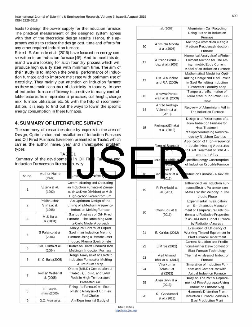
4. SUMMARY OF LITERATURE SURVEYThe summery of researches done by experts in the area ofDesign, Optimization and Installation of Induction Furnacesand Oil Fired Furnaces have been presented in Table1 whichcarries the author name, year and investigated problemtypes.
TABLE 1 Summary of the developments in Oil Fired Furnaces andInduction Furnaces on literature survey.
Sr. no.Author Name
(Year) Investigated Problem Type
1S. Jena at al.
(1992)
Commissioning and Operatingan Induction Furnace at Zimas-co (KweKwe Division) to MeltHigh-carbon Ferrochromium
2PritibhushanSinha at al.
(1998)
An Optimum Design of theLining of a Medium Frequency
Induction MeltingFurnace
3 M.S. liu atal.(2001)
Startup Analysis of Oil- FiredFurnace – The Smoothing Mon-
te Carlo Model Approach
4S. Palanco at al.
(2004)
Analytical Control of LiquidSteel in an Induction Melting
Furnace Using a Remote LaserInduced Plasma Spectrometer
5S.K. Dutta at al.
(2004)Studies on Direct Reduced Iron
Melting inInduction Furnace
6 K. C. Bala (2005)Design Analysis of an ElectricInduction Furnacefor Melting
Aluminium Scrap
7Roman Weber at
al. (2005)
On the (MILD) Combustion ofGaseous, Liquid, and SolidFuels in High Temperature
Preheated Air
8 H. Tauch-mann(2005)
Firing the Furnace? An Econ-ometric Analysis of Utilities
Fuel Choice9 G.O. Verran at An Experimental Study of
al. (2007) Aluminium Can RecyclingUsing Fusion in Induction
Furnace
10Arimichi Morita
at al. (2008)
Melting Automation Using aMedium FrequencyInduction
Furnace
11 Alfredo BermU-dez at al. (2009)
Numerical Analysis of a Finite-Element Method for The Ax-
isymmetric Eddy CurrentModel of an Induction Furnace
12O.K. Abubakreand R.A (2009)
Mathematical Model for Opti-mizing Charge and Heel Levels
in Steel Remelting InductionFurnace for Foundry Shop
13 AnuwatPansu-wan at al. (2009)
Temperature Estimation ofLiquid Steel in Induction Fur-
nace
14Antão RodrigoValentim at al.
(2010)
Recovery of Aluminium Foil inThe Induction Furnace
15 PashupatiDhakalat al. (2012)
Design and Performance of aNew Induction Furnace for
Heat Treatmentof Superconducting Radiofre-
quency Niobium Cavities
16Fang-ni Shang at
al. (2011)
Application of High-FrequencyInduction Heating Apparatusto Heat Treatment of 6061 Al-
uminium Alloy
17JaroslavBublík at
al. (2011)Specific Energy Consumptionof Induction Crucible Furnace
18Vivek R.
Gandhewar et al.(2011)
Induction Furnace - A Review
19R. Przy ucki at
al. (2011)
Influence of an Induction Fur-naces Electric Parameters on
Mass Transfer Velocity in TheLiquid Phase
20Chun Lou at al.
(2011)
Experimental Investigationon Simultaneous Measure-
ment of Temperature Distribu-tions and Radiative Propertiesin an Oil-Fired Tunnel Furnace
by Radiation Analysis
21 E. Kardas (2012)Evaluation of Efficiency of
Working Time of Equipment inBlast Furnace Department
22 J. Mróz (2012)Current Situation and Predic-tions Further Development of
Blast Furnace Technology
23Asif Ahmad
Bhat at al. (2012)Thermal Analysis of Induction
Furnace
24ViralkumarSolanki atal.(2013)
Simulation of Induction Fur-nace and ComparisonwithActual Induction Furnace
25 Ansu John at al.(2013)
Study on The Partial Replace-ment of Fine Aggregate Using
Induction Furnace Slag
26 S.L.Gbadamosiet al. (2013)
Harmonic Distortion FromInduction Furnace Loads in a
Steel Production Plant
609
IJSER
International Journal of Scientific & Engineering Research, Volume 6, Issue 8, August-2015ISSN 2229-5518
IJSER © 2015http://www.ijser.org
27 BhujbalNitin B.at al. (2013)
Optimization of Wall Thick-ness and Material for Mini-
mum Heat Losses for Induc-tion Furnace by FEA
28Sunil M. Jarali-
kar (2013)
Performance Analysis of anInduction FurnaceEmploying12 Pulse Converter- A Case
Study
29VipulGondaliya
at al. (2013)
Transient Heat transfer Analy-sis of Induction Furnace
by Using Finite Element Anal-ysis
30 Nihar P Bara(2013)
Finite Element Analysis OfInduction Furnace For Opti-
mum Heat Transfer
31 Ramesh Babu P.et al. (2013)
Elimination Of Harmonics OfInduction Furnace By applying
PQ-Theoryfor The Control Of Hybrid
Active Selective Filter
32Nihar Bara
(2013)Review Paper on Numerical
Analysis of Induction Furnace
33 Shri P.K.Thakurat al. (2014)
A Review On: Efficient EnergyOptimization in Reheating
Furnaces
34 Binoy C N at al.(2014)
Cost Reduction Using Alterna-tive Fuel in a ForgingIndustry
35Dr. R.K. Jain
(2014)
Experimentally InvestigatedEffect of FlameTemperature onPerformance of RotaryFurnace
36Dr. Ali K. M.
Alshaikhli at al.(2014)
Design and Construction of theCoreless Induction Furnace
37Sneha P. Gad-
payle et al.(2014)
Electric Melting Furnace - AReview
38O.A. Adeyemi1
et al. (2014)
Production of Ductile IronUsing Indigenously Manufac-
tured Rotary Furnace
39Kushal G. Ambli
at al. (2014)
Experimental Analysis andOptimization of Material Con-
sumption
40Prof .Uma Kul-
karni at al. (2014)
Design & Control of MediumFrequency Induction Furnace-
For Solar Grade Silicon
41Uma Kulkarni at
al. (2014)
Design and Control of MediumFrequency Induction Furnace
for Silicon Melting
42Prof. L.P.
Bhamare atal.(2015)
Furnace Monitoring andBillet Cutting System
43Ufuoma Peter
Anaidhuno et al.(2015)
Development of an ElectricInduction Furnace for Heat
Treatment of Ferrous and Non-Ferrous Alloys
44Isam M. Ab-dulbaqi at al.
(2015)
Design and Implementation ofan Induction Furnace
45 Rakesh S. Am-badeet al. (2015)
Energy Conservation In AnInduction Furnace: A New
Approach
5. DISCUSSIONSFrom the literature survey following points are needs to bediscussed:-
1. We have to focus on energy conservation, minimumconsumption maximum output policy should beapplied.
2. Now-a-days demand of steel is increasing due to in-crease in infrastructure and globalization. And tomeet this demand we are looking for such foundryprocess which will produce high quality steel withminimum time.
3. The improvement should be done in induction fur-nace and to improve melt rate with optimum use ofelectricity.
4. Finite Element Method (FEM) approach my be usedto reduce the design cost, time and efforts for anyother required induction furnace.
5. The furnace was constructed putting into considera-tion; its temperature attainment, capacity of metalsit can hold, the depth/surface area to be heat treat-ed, operators safety, space to be occupied in theworkshop floor, cost restrictions, availability of thematerials used, its maintainability and portability .
6. Furnace monitoring and billet cutting system maybe adapted in order to increase the efficiency.
7. Optimum thickness for reducing heat loss in fur-nace with economical cost is needed.
8. There are huge losses in the existing furnace hencewe have concluded that optimization is necessary.
9. Conversion of waste to energy is one of the recenttrends in minimizing not only the waste disposalbut also could be used as an alternate fuel for indus-tries.
10. Latest techniques and machines should be used.11. The integration of the furnaces can be done to meet
various requirements such as melting of metals.Various purposes can be achieved using the samefurnace.
12. Spillage of metal also incorporates the burning loss,as the burning loss is derived from loss of metal be-fore pouring and after pouring, therefore it is verymuch necessary to reduce the spillage of metalwhile it is melted form.
6. CONCLUSIONThrough the exhaustive review of literature, the basic opera-tions of induction furnace and importance of its individualparameters are studied. Through the literature we have ob-served that the efficiency of oil fired furnaces is less becauseof heat losses. So there exists the opportunities for improv-ing the efficiency of steel melting processes by using the in-duction process. The induction furnace should be designed,optimize and install carefully in order to maximize the rateof production and minimize cost of production.
610
IJSER
International Journal of Scientific & Engineering Research, Volume 6, Issue 8, August-2015ISSN 2229-5518
IJSER © 2015http://www.ijser.org
7. REFERENCES
[1] S. Jena and S.T. Ravastngadi,“Commissioning and Operating anInduction Furnace at Zimasco (KweKwe Division) to Melt High-carbon Ferrochromium”, IFACON 6 ; Proceedings of the 6th In-ternational Ferroalloys Congress ,Cape Town , Volume 1 , Jo-hannesburg, SAIMM, 1992 , Pages 113-118
[2] Pritibhushan Sinha and SubhashSaha Chandra, “An OptimumDesign of the Lining of a Medium Frequency Induction MeltingFurnace”, International Transactions in Operational ResearchVol. 5, No. 4, Pages 255-259
[3] M. S. Liu ,C. K. Choi and C. W. Leung, “Start-up Analysis ofOil- Fired Furnace – The Smoothing Monte Carlo Model Ap-proach”, Heat and Mass Transfer 37 (2001) Springer- Verlag2001 , Pages 449–457.
[4] S. Palanco, S. Conesa and J. J. Laserna, “Analytical Control ofLiquid Steel in an Induction Melting Furnace Using a Remote LaserInduced Plasma Spectrometer” J. Anal. At. Spectrom. ; 2004, 19,Pages 462 – 467
[5] S.K. Dutta, A.B. Lele and N.K. Pancholi, “Studies on DirectReduced Iron Melting in Induction Furnace”, Trans. IndianInst. Met.Vol.57, No. 5, October 2004; Pages 467-473
[6] K. C. Bala, “Design Analysis of an Electric Induction Furnace forMelting Aluminium Scrap”, AU J.T. 9(2): 83-88 (Oct. 2005), Pag-es 83-88
[7] Roman Weber, John P. Smart, Willem vd Kamp, “On the(MILD) Combustion of Gaseous, Liquid and Solid Fuels in HighTemperature Preheated Air”, Proceedings of the Combustion In-stitute 30 (2005), Pages 2623–2629
[8] H. Tauchmann, “Firing the furnace? An Econometric Analysis ofUtilities Fuel Choice”, Energy Policy 34 (2006), Pages 3898–3909
[9] G.O. Verran and U. Kurzawa, “An Experimental Study of Alu-minium Can Recycling Using Fusion in Induction Furnace”, Re-sources Conservation and Recycling 52 (2008), Pages 731–736
[10] Arimichi Morita and Toshiyuki Kano, “Melting AutomationUsing a Medium-Frequency Induction Furnace”, Int. J. of Auto-mation Technology Vol.2 No.4, 2008, Pages 276-277
[11] Alfredo Berm Udez, Carlos Reales , Rodolfo Rodr, Guez PilarSalgado, “ Numerical Analysis of a Finite-Element Method for TheAxisymmetric Eddy Current Model of an Induction Furnace”, IMAJournal of Numerical Analysis Advance Access publishedMarch 12, 2009, Page 1 -23
[12] O.K. Abubakre and R.A. Muriana, “Mathematical Model for Op-timizing Charge and Heel Levels in Steel Remelting Induction Fur-nace for Foundry Shop”, Journal of Minerals & Materials Char-acterization & Engineering, Vol. 8, No.6, 2009, Pages 417-425
[13] Anuwat Pansuwan, Krit Smerpitak and Prapart Uka-kimaparn, “Temperature Estimation of Liquid Steel in InductionFurnace”, Proceedings of the International Multi Conferenceof Engineers and Computer Scientists 2009 Vol II IMECS 2009,March 18 - 20, 2009, Hong Kong
[14] Antao Rodrigo Valentim, Ivanir Luiz de Oliveira, Joao LuizKovaleski, “ Recovery of Aluminium Foil in The Induction Fur-nace”, XVI International Conference on Industrial Engineeringand Operations Management, Sao Carlos, SP, Brazil, 12 to 15October – 2010, Pages 1-8
[15] Pashupati Dhakal, Gianluigi Ciovati Wayne Rigby, John Wal-lace, and Ganapati Rao Myneni, “Design and Performance of ANew Induction Furnace for Heat Treatment of SuperconductingRadio frequency Niobium Cavities”, The review of scientific in-struments , June 2012, Pages 1-5
[16] Fang-ni Shang, Eiji Sekiya and Yoshihiro Nakayama, “Applica-tion of High-Frequency Induction Heating Apparatus to HeatTreatment of 6061 Aluminium Alloy Materials Transactions,” Vol.52, No. 11 (2011), Pages 2052 - 2060
[17] Jaroslav Bublik, Matej Abraham, “Specific Energy Consumptionof Induction Crucible Furnace”, May 2011, ZeleznaRuda-Spicak,University of West Bohemia, Czech Republic, Pages 130-133
[18] Vivek R. Gandhewar, Satish V. Bansod, Atul B. Borade, “In-duction Furnace - A Review”, International Journal of Engineer-ing and Technology Vol.3 (4), 2011, Pages 277-284
[19] R. Przylucki, S. Golak, B. Oleksiak, L. Blacha, “Influence of anInduction Furnace’s Electric parameters on Mass Transfer Velocityin The Liquid Phase”, Metalurgija 51 (2012) 1, Pages 67-70
[20] Chun Lou a, Wen-Hao Li a, Huai-Chun Zhou a, Carlos T. Sa-linas, “Experimental Investigation on Simultaneous Measurementof Temperature Distributions and Radiative Properties in an Oil-Fired Tunnel Furnace by Radiation Analysis”, International Jour-nal of Heat and Mass Transfer 54 (2011), Pages 1–8
[21] E. Kardas, “Evaluation of Efficiency of Working Time of Equip-ment in Blast Furnace Department”, Journal of Achievements inMaterials and Manufacturing Engineering Volume 55 Issue 2December 2012, Pages 876-880
[22] J. Mroz,“Current Situation and Predictions Further Developmentof Blast Furnace Technology”, Journal of Achievements in Mate-rials and Manufacturing Engineering Volume 55 Issue 2 De-cember 2012, Pages 889-894
[23] A. A. Bhat, S. Agarwal, D. Sujish, B. Muralidharan, B. P. Red-dy, G. Padmakumar and K. K. Rajan, “Thermal Analysis of In-duction Furnace”, Excerpt from the proceedings of the 2012COMSOL Conference Bangalore
[24] Viralkumar Solanki, Sanjay R Joshi, Jiten Chavda, Kashyap-Mokariya, “Simulation of Induction Furnace and Comparison withActual Induction Furnace”, International Journal of RecentTechnology and Engineering, Volume-2, Issue-4, September2013, Pages 105-109
[25] Ansu John and Elson John, “Study on the Partial Replacement ofFine Aggregate Using Induction Furnace Slag”, American Jour-nal of Engineering Research (AJER)2013, Volume-4, Pages 01-05
[26] S. L. Gbadamosi, A. O. Melodi , “Harmonic Distortion From In-duction Furnace Loads in a Steel Production Plant”, Network andComplex Systems Vol.3, No.10, 2013, Pages 8-16
[27] Bhujbal Nitin B. , Prof. S. B. Kumbhar, “Optimization of WallThickness and Material for Minimum Heat Losses For InductionFurnace by FEA”, International Journal of Mechanical Engi-neering and Technology (IJMET) Volume 4, Issue 2, Pages418-428
[28] Sunil M. Jaralikar, “Performance Analysis of an Induction Fur-nace Employing 12 Pulse Converter- A Case Study ;InternationalJournal of Advanced Research in Electrical”, Electronics and In-strumentation Engineering Vol. 2, Issue 7, July 2013, Pages3414-3421
[29] Vipul Gondaliya, Mehul Pujaraand Niraj Mehta,“TransientHeat Transfer Analysis of Induction Furnace by Using Finite Ele-ment Analysis”, Indian Journal of Applied Research Volume 3Issue 8, Aug 2013, Pages 231-234
[30] Nihar P Bara (2013), “ Finite Element Analysis Of Induction Fur-nace For Optimum Heat Transfer”, International Journal of In-novative Research in Science, Engineering and TechnologyVol. 2 , Issue 5 , May 2013, Pages 1313-1319
[31] Ramesh Babu P, Ashisa Dash , Smruti Rajan Panda, “ Elimina-tion Of Harmonics Of Induction Furnace By applying PQ-Theory
611
IJSER
International Journal of Scientific & Engineering Research, Volume 6, Issue 8, August-2015ISSN 2229-5518
IJSER © 2015http://www.ijser.org
for the Control Of Hybrid Active Selective Filter”, InternationalJournal of Engineering Research and Applications, Vol. 3,Issue 3 , May – June 2013 , Pages 180-185
[32] Nihar Bara, “Review Paper on Numerical Analysis of InductionFurnace”, International Journal of Latest Trends in Engineer-ing and Technology (IJLTET) Vol. 2 Issue 3 May 2013, Pages178-184
[33] Shri P. K. Thakur, Shri K. Prakash, Shri K. G. Muralidharan,V. Bahl, Shri S. Das, “A Review on: Efficient Energy Optimizationin Reheating Furnaces”, Proceedings of 16th IRF InternationalConference, 14th December 2014, Pune, India, Pages 43-49
[34] Binoy C N, Joseph George, Sijo M T, “Cost Reduction Using Al-ternative Fuel in a Forging Industry International Journal of Scien-tific and Research Publications”, Pages 1-5
[35] Dr. R.K. Jain,“Experimentally Investigated Effect of Flame Tem-perature on Performance of Rotary Furnace”, IPASJ InternationalJournal of Mechanical Engineering (IIJME); Volume 2, Issue 3,March 2014, Pages 20-28
[36] Dr. Ali K. M. Alshaikhli, Dr. Mohammed M. Al-Khairo, Hay-der K. Jahanger, Fatima H. Faris, “Design and Construction ofthe Coreless Induction Furnace”,International Journal of Scien-tific & Engineering Research, Volume 5, Issue 1, January-2014,Pages 697-705
[37] Sneha P. Gadpayle, Rashmi N. Baxi,“Electric Melting Furnace -A Review”, International Journal of Emerging Science and En-gineering (IJESE) Volume-2, Issue-5, March 2014, Pages 80-83
[38] O.A. Adeyemi, I.M. Momoh, S.O.O. Olusunle and S.B.Adejuyigbe,“Production of Ductile Iron Using IndigenouslyManufactured Rotary Furnace”, IOSR Journal of Mechanicaland Civil Engineering Volume 11, Issue 5 Ver. I (Sep- Oct.2014); Pages 62-65
[39] Kushal Ambli, “Experimental Analysis and Optimization of Ma-terial Consumption” International Journal of Research in Engi-neering and Technology, Volume: 03 Issue: 03 Mar-2014,Pages 74-81
[40] Prof. Uma Kulkarni, Dr. Uday Wali, “Design & Control of Me-dium Frequency Induction Furnace For Solar Grade Silicon”, In-ternational Conference on Advanced Developments in Engi-neering and Technology, Volume 4, Special Issue 1, February2014, Pages 230-233
[41] Uma Kulkarni, Sushant Jadhav, Mahantesh, “Design and Con-trol of Medium Frequency Induction Furnace for Silicon Melting”International Journal of Engineering Science and InnovativeTechnology Volume 3, Issue 4, July 2014, Pages 269-276
[42] Prof. L.P. Bhamare, Nikita V. Shejwal, Priyanka S. Patil, Poo-nam C. Jadhav, “Furnace Monitoring and Billet Cutting System”,International Journal of Innovation and Scientific ResearchVol. 15 No. 1 May 2015, Pages 175-179
[43] Ufuoma Peter Anaidhuno, Chinedum Ogonna Mgbemena,“Development of an Electric Induction Furnace for Heat Treatmentof Ferrous and Non-Ferrous Alloys”, American Journal of Engi-neering Research (AJER) Volume-4, Issue-5, Pages 29-35
[44] Isam M. Abdulbaqi, Abdul-Hasan A. Kadhim, Ali H. Abdul-Jabbar, Fathil A. Abood, Turki K. Hasan, “Design And Imple-mentation Of An Induction Furnace”, Design andEngineeringSciences, Vol. 08, No. 01, March 2015, Pages 64-82
[45] Implementation of an Induction Furnace”, Diyala Journal ofRakesh S. Ambade, Akshay P. Komawar, Disha K. Paigwar,Shweta V. Kawale, “A Energy Conservation in an Induction Fur-nace: A New Approach”, International Journal of AdvancedTechnology in Engineering and Science, Volume No 03, Spe-cial Issue No. 01, April 2015, Pages 153-160
[46] Coal and Industrial Furnaces – Department of Coal Publica-tions, Government of India, 1985
[47] Fuel Economy in furnaces and Waste heat recovery-PCRA[48] Industrial Furnaces (Vol-2) by W.Trinks, John Wiley and Sons
Inc, Newyork, 1925[49] Output of seminar on energy conservation in iron and steel
industry - Sponsored by United Nations Industrial Devel-opment Organization (UNIDO) and Ministry of InternationalTrade and Industry (MITI), Japan
[50] Prof. S. R. Satish Kumar and Prof. A. R. Santha Kumar, “De-sign of Steel Structures” Indian Institute of Technology Madras
[51] Oil Fired Crucible Furnace, For Melting and Holding Alumin-ium Model CFD-500,http://www.khi.sg/cmtsproduct/images/ecatalogue/pdf/15-oil-fired crucible-furnace.pdf
[52] Bureau of Energy Efficiency, Ministry of Power, India, “Ener-gy Efficiency in Thermal Utilities”, 2005
[53] “Induction Furnace”,http://viewforyou.blogspot.in/2008/10/inductionfurnace.html,2008-2010
[54] Jean Callebaut, Laborelec, 2014, “Application Note InductionHeating”, ECI Publication No Cu0123, www.leonardo-energy.org
[55] Umit Unver, H. Murat Unver, “Comparison of Natural Gas Firedand Induction Heating Furnaces”, Yalova Universitesi, KazimKarabekir Mah. Rahmi Ustel Cad. No1 , Yalova Turkey Ki-rikkale Universitesi, Muhendislik Fakültesi Yahsihan KirikkleTurkey, 2013
[56] Akash Khaitan, “A Report on Induction Furnace”, Nikita Metals,Kalyaneshwari, Burdwan, W.B. An Internship Program-II sta-tion of Faculty of Science & Technology, ICFAI University 26th May-17th July, 2010
[57] Gulfam Hussain, “Electric Induction Furnace” ,http://www.slideshare.net/e_gulfam/induction-furnace-42135932 , 2014
[58] Energy Efficiency Enquiries Bureau , “Efficient Melting In Core-less Induction Furnaces”, Guide is No. 50 (revised) in the GoodPractice Guide Series ,https://lists.man.lodz.pl/pipermail/odlew-pl/2012/10/att0003/guide_coreless_induction_furnaces.pdf
612
IJSER

International Journal of Scientific & Engineering Research, Volume 6, Issue 8, August-2015ISSN 2229-5518
IJSER © 2015http://www.ijser.org
613
IJSER