ol3 - javascript library for 3d scenes - mei
TRANSCRIPT

University of MinhoInformatics Department
Master in Informatics
OL3 - JavaScript library for 3D scenes
Bruno Gustavo Rego Amaral da Costa
Supervised by:
Professor Doutor Jorge Gustavo Rocha
Braga, October 30, 2012

Abstract
The main purpose of this thesis is the implementation of an open sourceJavaScript library for the navigation of dynamic three-dimensional scenesthrough the browser, using asynchronous data from different servers andwithout the need for plugins.
Due to the recent developments of Hypertext Markup Language (HTML)5and the new capabilities of JavaScript for supporting 3D graphics using WebGraphics Library (WebGL), users can now break free from the traditionaltwo dimensional web, and experience three-dimensional scenes through thebrowser. Using these new specifications a library for the visualisation andnavigation of three-dimensional scenes is a step towards a more immersiveexperience of the web. The library should be capable of loading geometrydata from servers asynchronously and provide tools for a free and immersivenavigation of the scenes obtained from the server.
The library was developed and most functionalities were implemented,such as asynchronous loading of data and navigation. Data management ispartly implemented, as there are still some issues regarding the overlapping ofgeometry, but the issue is well defined and a solution is nearly implemented.
Overall, the library has it’s strong points and issues, yet it is almost readyto be usable. Further work is still required and additional possibilities andfunctions can be studied and implemented.
i


Resumo
O objetivo desta tese é a implementação de uma biblioteca JavaScript opensource para a navegação de cenas tridimensionais dinâmicas através dobrowser, utilizando dados assíncronos de diferentes servidores e sem a ne-cessidade de plugins.
Tendo em conta os recentes desenvolvimentos do HTML5 e as novas ca-pacidades do JavaScript para suportar gráficos 3D recorrendo ao WebGL, osutilizadores podem agora libertar-se da barreira bidimensional da web tradi-cional, e experiênciar cenas tridimensionais através do browser. Utilizandoestas novas especificações, uma biblioteca para a navegação e visualizaçãode cenas tridimensionais é um passo em frente para uma experiência maisimersiva da web. A biblioteca deve ser capaz de carregar geometria a partirde servidores assincronamente e fornecer ferramentas para uma navegaçãolivre e imersiva das cenas obtidas do servidor.
A biblioteca foi desenvolvida e a maioria das funcionalidades foram imple-mentadas tais como carregamento de dados assíncronos e navegação. Gestãodos dados está parcialmente implementada, no entanto ainda existem algu-mas falhas no sobreposicionamento de geometria, no entanto a falha está bemdefinida e uma solução está prestes a ser implementada.
De um ponto de vista geral, a biblioteca tem pontos fortes e algumasfalhas, no entanto está quase pronta a ser utilizada. Trabalho futuro ainda épreciso, tal como o estudo de novas funcionalidades e a sua implementação.
iii


Contents
Listings viii
List of Figures x
Acronyms xii
1 Introduction 11.1 Objectives . . . . . . . . . . . . . . . . . . . . . . . . . . . . . 21.2 Thesis Outline . . . . . . . . . . . . . . . . . . . . . . . . . . . 2
2 State of the Art 52.1 WebGL . . . . . . . . . . . . . . . . . . . . . . . . . . . . . . 52.2 Extensible 3D . . . . . . . . . . . . . . . . . . . . . . . . . . . 9
2.2.1 Profiles and Components . . . . . . . . . . . . . . . . . 102.2.2 X3D File Structure . . . . . . . . . . . . . . . . . . . . 112.2.3 User interaction . . . . . . . . . . . . . . . . . . . . . . 13
2.3 X3DOM . . . . . . . . . . . . . . . . . . . . . . . . . . . . . . 152.3.1 X3Dom Architecture . . . . . . . . . . . . . . . . . . . 17
2.4 OpenLayers . . . . . . . . . . . . . . . . . . . . . . . . . . . . 202.4.1 Using OpenLayers . . . . . . . . . . . . . . . . . . . . 21
2.5 WebGL Earth . . . . . . . . . . . . . . . . . . . . . . . . . . . 282.6 Web 3D Service . . . . . . . . . . . . . . . . . . . . . . . . . . 31
2.6.1 GetCapabilities . . . . . . . . . . . . . . . . . . . . . . 322.6.2 GetScene . . . . . . . . . . . . . . . . . . . . . . . . . 322.6.3 GetTile . . . . . . . . . . . . . . . . . . . . . . . . . . 33
v

Contents
2.6.4 GetLayerInfo . . . . . . . . . . . . . . . . . . . . . . . 332.6.5 GetFeatureInfo . . . . . . . . . . . . . . . . . . . . . . 33
3 Implementation 353.1 JavaScript Object and Initial Requirements . . . . . . . . . . . 35
3.1.1 Object Oriented Programming in JavaScript and theOL3 Object . . . . . . . . . . . . . . . . . . . . . . . . 36
3.1.2 Asynchronous Communication with the Web Server . . 373.1.3 GetCapabilities . . . . . . . . . . . . . . . . . . . . . . 393.1.4 Bounding Box . . . . . . . . . . . . . . . . . . . . . . . 40
3.2 OL3 Structures . . . . . . . . . . . . . . . . . . . . . . . . . . 423.2.1 Scene . . . . . . . . . . . . . . . . . . . . . . . . . . . . 423.2.2 Camera Implementation . . . . . . . . . . . . . . . . . 433.2.3 Layer . . . . . . . . . . . . . . . . . . . . . . . . . . . . 52
4 OL3 in Action 594.1 Manage code development using Git . . . . . . . . . . . . . . 59
4.1.1 Complementary code management tools . . . . . . . . 604.2 How to get OL3 code . . . . . . . . . . . . . . . . . . . . . . . 604.3 How to create a very basic map . . . . . . . . . . . . . . . . . 624.4 How to contribute to the OL3 development . . . . . . . . . . . 64
5 Conclusions and Future Work 675.1 Research . . . . . . . . . . . . . . . . . . . . . . . . . . . . . . 675.2 Implementation . . . . . . . . . . . . . . . . . . . . . . . . . . 695.3 Future Work . . . . . . . . . . . . . . . . . . . . . . . . . . . . 715.4 Conclusion . . . . . . . . . . . . . . . . . . . . . . . . . . . . . 71
vi
Listings
2.1 JavaScript code required to initialize the WebGLRendering-Context . . . . . . . . . . . . . . . . . . . . . . . . . . . . . . 6
2.2 Html required to initialize the scene . . . . . . . . . . . . . . . 62.3 init function . . . . . . . . . . . . . . . . . . . . . . . . . . . . 72.4 initWebGL function . . . . . . . . . . . . . . . . . . . . . . . . 72.5 initBuffers function . . . . . . . . . . . . . . . . . . . . . . . . 82.6 drawScene function . . . . . . . . . . . . . . . . . . . . . . . . 92.7 X3D syntax necessary for the creation of a scene with a blue
sphere . . . . . . . . . . . . . . . . . . . . . . . . . . . . . . . 112.8 Creating a map with OpenLayers . . . . . . . . . . . . . . . . 212.9 OpenLayers constructor . . . . . . . . . . . . . . . . . . . . . 212.10 Creating a OpenLayers layer . . . . . . . . . . . . . . . . . . . 222.11 OpenLayers map with different layers . . . . . . . . . . . . . . 232.12 Creating additional controls . . . . . . . . . . . . . . . . . . . 252.13 Creating a Graticule control . . . . . . . . . . . . . . . . . . . 262.14 Creating a Point of Interest with text . . . . . . . . . . . . . . 262.15 Textfile needed for creating a Point of Interest with text . . . 262.16 Creating a WebGL Earth globe . . . . . . . . . . . . . . . . . 292.17 Options object for WebGL Earth . . . . . . . . . . . . . . . . 293.1 Class implementation . . . . . . . . . . . . . . . . . . . . . . . 363.2 New class definition . . . . . . . . . . . . . . . . . . . . . . . . 373.3 Instantiating a new Person Object . . . . . . . . . . . . . . . . 373.4 Example of XMLHttpRequest using jQuery . . . . . . . . . . 383.5 Example of a GetCapabilities reply describing a get scene request 393.6 Creating a Scene . . . . . . . . . . . . . . . . . . . . . . . . . 42
vii

Listings
3.7 Scene default variables . . . . . . . . . . . . . . . . . . . . . . 423.8 Emitting a ray . . . . . . . . . . . . . . . . . . . . . . . . . . 483.9 Intersection of a plane with a line function . . . . . . . . . . . 503.10 Creating a new Layer . . . . . . . . . . . . . . . . . . . . . . . 523.11 Calculating the grid’s columns and rows . . . . . . . . . . . . 544.1 Obtaining the library source code . . . . . . . . . . . . . . . . 614.2 Making a commit . . . . . . . . . . . . . . . . . . . . . . . . . 614.3 Making a commit . . . . . . . . . . . . . . . . . . . . . . . . . 614.4 Including the libraries . . . . . . . . . . . . . . . . . . . . . . 624.5 Including the OL3 library files . . . . . . . . . . . . . . . . . . 624.6 Setting up a scene . . . . . . . . . . . . . . . . . . . . . . . . . 624.7 The HTML body for using a scene . . . . . . . . . . . . . . . 634.8 Function syntax . . . . . . . . . . . . . . . . . . . . . . . . . . 644.9 Class syntax . . . . . . . . . . . . . . . . . . . . . . . . . . . . 65
viii

List of Figures
2.1 Graphical result of Listing 2.7 . . . . . . . . . . . . . . . . . . 142.2 X3DOM Profile compared with existing X3D Profiles . . . . . 192.3 HTML page with an OpenLayers map . . . . . . . . . . . . . 222.4 OpenLayers map with a simple WMS layer . . . . . . . . . . . 232.5 OpenLayers map with a multiple layers . . . . . . . . . . . . . 242.6 OpenLayers map with a inactive layer . . . . . . . . . . . . . . 252.7 OpenLayers map with active layer . . . . . . . . . . . . . . . . 252.8 OpenLayers map with Graticule overlay . . . . . . . . . . . . 262.9 OpenLayers map with Points of Interest . . . . . . . . . . . . 272.10 OpenLayers map with Points of Interest and related informa-
tion box . . . . . . . . . . . . . . . . . . . . . . . . . . . . . . 272.11 OpenLayers map with vector shapes . . . . . . . . . . . . . . . 282.12 WebGL Earth globe . . . . . . . . . . . . . . . . . . . . . . . 302.13 WebGL Earth globe zoomed in . . . . . . . . . . . . . . . . . 31
3.1 3D Bounding box (left) and current implementation (right) . . 413.2 Camera viewing frustum - obtained in Lighthouse3d.com . . . 453.3 Loaded geometry for a untiled model using a GetScene request 543.4 Loaded geometry for a untiled model using a GetScene request
and tiled geometry using a GetTile request . . . . . . . . . . . 553.5 Grid representation . . . . . . . . . . . . . . . . . . . . . . . . 553.6 Temporary Grid construction . . . . . . . . . . . . . . . . . . 563.7 Temporary Grid layout . . . . . . . . . . . . . . . . . . . . . . 58
4.1 Web interface of the OL3 repository . . . . . . . . . . . . . . . 61
ix


Acronyms
AJAX Asynchronous JavaScript and XML. x, 20, 35, 39
API Application programming interface. x, 2, 5, 6, 16, 20, 32, 38, 67
CAD Computer-aided Design. x, 11
CRS Coordinate Reference System. x, 40, 41
CSS Cascading Style Sheets. x, 16
DID Distributed Interactive Simulation. x, 11
DOM Document Object Model. x, 5, 7, 15–18, 43, 53, 68, 70
DTD Document Type Definition. x, 12
GeoJSON Geo JavaScript Object Notation. x, 21
GeoRSS GeoRSS-Simple. x, 21
GIS Geographic Information System. x
GLSL OpenGL Shading Language. x, 5
GML Geography Markup Language. x, 21
HTML Hypertext Markup Language. i, iii, x, 1, 2, 5–7, 15, 17, 21, 25, 28,29, 35, 42–44, 51, 53, 62, 64, 67, 68, 70, 71
HTTP Hypertext Transfer Protocol. x, 38
xi

Acronyms
KML Keyhole Markup Language. x, 21
LOD Level of Detail. x, 32, 33, 40, 54–58, 70, 71
NURBS Non-uniform Rational Basis Spline. x, 11
OpenGL Open Graphics Library. x, 5, 6, 9, 16, 17
OpenGL ES OpenGL for Embedded Systems. x, 5, 6
OS Operating System. x, 17
SAI Scene Access Interface. x, 20
SVG Scalable Vector Graphics. x, 16, 17, 19
URL Uniform Resource Locator. x, 39, 52
VRML Virtual Reality Modeling Language. x, 1, 9, 16, 68
VRML97 Virtual Reality Modeling Language 2.0. x, 9, 11
W3C World Wide Web Consortium. x, 31
W3DS Web 3D Service. x, 2, 31, 32, 39–42, 52–55, 57, 58, 64, 67–70
WebGL Web Graphics Library. i, iii, x, 1, 2, 5–7, 9, 28, 67
WMS Web Map Server. x, 22, 23, 31, 69
X3D Extensible 3D. x, 2, 9–20, 31, 32, 35, 43, 53, 67, 68
X3DOM Extensible 3D Document Object Model. x, 2, 15, 17–20, 33, 35,43–46, 48, 62, 64, 67, 68, 70
XHR XMLHttpRequest. x, 38
XML Extensible Markup Language. x, 9, 11–13, 17, 32, 33, 38–40, 68
xii

Chapter 1
Introduction
With the development of HTML5 and the increased capabilities of JavaScript,including the support for 3D graphics through the use of WebGL, one shouldconsider the impact and the new opportunities those specifications allow.Until now, the usage of 3D graphics was made using plug-ins, like VirtualReality Modeling Language (VRML) or Flash forcing the user to install thirdparty software. With HTML5 and WebGL, the browser can now take ad-vantage of the processing power offered by the graphic card, thus allowingthe users to access 3D contents using the computer display card’s GraphicsProcessing Unit out of the box.
One field which would greatly benefit from the adaptation to a three-dimensional navigation system would be mapping software. The current prac-tice in map navigation through the browser is made in a two dimensionalsystem; users can pan the map around and zoom in and out, but the viewpointis always from above and there is no perception of the space. As we experiencethe world in a multidimensional way and not in a top-down two-dimensionalpoint of view, browsing a map as a three-dimensional representation seemsmore similar to our experiences on our daily life than a two dimensional one.
Using the emerging specifications and the similarity to our daily life whichthree dimensions allow, the creation of a library to navigate three-dimensionalscenes is a step towards a better immersive experience in map navigation.Taking as reference the existing libraries of two-dimensional maps, an analysis
1
Chapter 1. Introduction
was made of the essential elements for navigation and then adapting them toa three-dimensional world. From this analysis, two key points were found: thefirst is obtaining the data which represents the geometry of the scene throughasynchronous requests, the second is to supply the user with an adequateApplication programming interface (API) which allows him to create a richweb application whose functionality is the navigation of a scene with all thefreedom three dimensions can allow.
The goal of this work is to develop a client side library to help the de-velopment of rich web 3D applications. The library will provide the corecomponents to create such 3D web applications, like getting 3D data fromremote servers, combine different 3D scenes and navigation controls.
1.1 Objectives
The objective of this thesis is the investigation of the current technologiesfor 3D scene visualization in the browser as well as the available open sourceclient-side web mapping solutions.
The practical result of the investigation is the development of a JavaScriptlibrary that allows users to visualize and navigate dynamic three-dimensionalscenes through the browser, using asynchronous data from different serversthrough HTML5 and Extensible 3D (X3D), without the need for plug-ins.The objective of this library is to provide a platform for the developmentof rich client-side web applications that allow navigation in 3D scenes withasynchronous loading of geometry data.
1.2 Thesis Outline
Chapter 2 (State of the Art) gives an overview of the current technolo-gies which enable the creation of the library such as WebGL, X3D,Extensible 3D Document Object Model (X3DOM) and Web 3D Service(W3DS). A study was also made gathering information about existing
2

Chapter 1. Introduction
JavaScript libraries used in scene navigation, which were analyzed as afoundation for the structure and usability of OL3, namely OpenLayersand WebGL Earth.
Chapter 3 (Implementation) illustrates the implementation of the Ol3library. Beginning with a small introduction about Object OrientedProgramming in JavaScript and name spaces, required to create the Ol3object, this section presents the basic functions needed for the library;asynchronous communication with the web server, the GetCapabilitiesrequest and the bounding box. After describing the previous elements,this chapter details the library’s different objects, the Scene, the Cameraand the Layer.
Chapter 4 (OL3 in Action) provides a description of how the code wasmanaged during the development stages, as well as how to obtain thecode and implement new classes. This chapter also has a small tutorialin how to setup a small scene in the browser.
Chapter 5 (Conclusions and Future Work) is a summary of the thesis,as well as a discussion of the issues left unresolved and a reflection ofthe paths left open and how they might be approached.
3

Chapter 1. Introduction
4
Chapter 2
State of the Art
Prior to the development of the library, a study was made. Existing librarieswere found and their capabilities were studied, in order to identify their strongpoints and flaws. Due to the innovations presented by this library there arefew reference works, thus we present scarce information, and there are noopen source libraries for map browsing which allow the users to navigate amap in three dimensions using the browser.
The current state of technologies was also reviewed, as to find suitabletools to develop the library, and to provide the readers with some backgroundinformation about the new specifications used in the development of thelibrary.
2.1 WebGL
WebGL is an API which is used to create 3D graphics in a Web browser. Itsspecification[2] was released in March 2011 and is managed by the KhronosGroup. This specification, based in OpenGL for Embedded Systems (OpenGLES) 2.0, allows the use of OpenGL Shading Language (GLSL) and is semanti-cally similar to the standard Open Graphics Library (OpenGL) API. WebGLuses HTML5 Canvas element as Document Object Model (DOM) interfaceand, being a DOM API, WebGL can be used with DOM compatible languageslike JavaScript, and is supported in most browsers. There are also libraries for
5
Chapter 2. State of the Art
WebGL development, such as WebGLU, X3DOM, Processing.js, SpiderGLand PhiloGL.
Desktop browser support is widely available, as Mozilla Firefox, GoogleChrome, Safari and Opera have WebGL implemented, leaving Internet Ex-plorer as the notable exception. WebGL has also penetrated the mobile plat-forms, as some mobile browsers have WebGL support, mostly present in theAndroid operating system.
The HTML Canvas element is a rendering destination in web pages, andallows the use of different rendering APIs such as CanvasRenderingContext2Dand WebGLRenderingContext. This context is where the WebGL API resides.This API can be used with Libraries or with OpenGL ES 2.0.
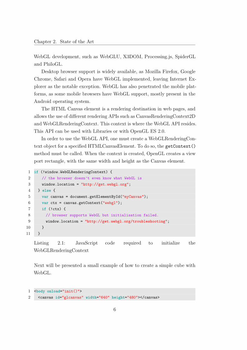
In order to use the WebGL API, one must create a WebGLRenderingCon-text object for a specified HTMLCanvasElement. To do so, the getContext()method must be called. When the context is created, OpenGL creates a viewport rectangle, with the same width and height as the Canvas element.
1 if (!window.WebGLRenderingContext) {2 // the browser doesn’t even know what WebGL is3 window.location = "http://get.webgl.org";4 } else {5 var canvas = document.getElementById("myCanvas");6 var ctx = canvas.getContext("webgl");7 if (!ctx) {8 // browser supports WebGL but initialisation failed.9 window.location = "http://get.webgl.org/troubleshooting";
10 }11 }
Listing 2.1: JavaScript code required to initialize theWebGLRenderingContext
Next will be presented a small example of how to create a simple cube withWebGL.
1 <body onload="init()">2 <canvas id="glcanvas" width="640" height="480"></canvas>
6

Chapter 2. State of the Art
3 </body>
Listing 2.2: Html required to initialize the scene
The HTML canvas element will contain the WebGL view port. When thebody element is loaded, the init() function will run.
1 function init() {2 var canvas = document.getElementById("glcanvas");3 initWebGL(canvas);4 if (gl) {5 gl.clearColor(0.0, 0.0, 0.0, 1.0);6 gl.enable(gl.DEPTH_TEST);7 gl.depthFunc(gl.LEQUAL);8 gl.clear(gl.COLOR_BUFFER_BIT|gl.DEPTH_BUFFER_BIT);9 initBuffers();
10 setInterval(drawScene, 15);11 }12 }
Listing 2.3: init function
The init function, as depicted in listing 2.3, will obtain the canvas elementfrom the DOM and will use the initWebGL, listing 2.4, to create the We-bGLRenderingContext.
Having a valid WebGLRenderingContext object, the buffers are initiatedusing the initBuffers function, as shown in listing 2.5. This function willcreate the vertices array, vertex index array and the colors array. Then itwill create the necessary array buffers. The drawScene function, as shownin listing 2.6, will be executed at a regular interval clearing the canvas anddrawing the cube.
1 function initWebGL(canvas) {2 gl = null;3 try {4 gl = canvas.getContext("webgl") || canvas.getContext("experimental-
webgl");5 }6 catch(e) {}
7

Chapter 2. State of the Art
7 }
Listing 2.4: initWebGL function
1 function initBuffers() {2 var vertices = [3 -1.0, -1.0, 1.0,4 1.0, -1.0, 1.0,5 //cut due to large amount of lines6 -1.0, 1.0, -1.07 ];89 var colors = [
10 [1.0, 1.0, 1.0, 1.0], // Front face: white11 [1.0, 0.0, 0.0, 1.0], // Back face: red12 [0.0, 1.0, 0.0, 1.0], // Top face: green13 [0.0, 0.0, 1.0, 1.0], // Bottom face: blue14 [1.0, 1.0, 0.0, 1.0], // Right face: yellow15 [1.0, 0.0, 1.0, 1.0] // Left face: purple16 ];17 var generatedColors = [];1819 for (j=0; j<6; j++) {20 var c = colors[j];21 for (var i=0; i<4; i++) {22 generatedColors = generatedColors.concat(c);23 }24 }2526 cubeVerticesColorBuffer = gl.createBuffer();27 gl.bindBuffer(gl.ARRAY_BUFFER, cubeVerticesColorBuffer);28 gl.bufferData(gl.ARRAY_BUFFER, new Float32Array(generatedColors), gl.
STATIC_DRAW);2930 cubeVerticesIndexBuffer = gl.createBuffer();31 gl.bindBuffer(gl.ELEMENT_ARRAY_BUFFER, cubeVerticesIndexBuffer);32 var cubeVertexIndices = [33 0, 1, 2, 0, 2, 3,34 4, 5, 6, 4, 6, 7,35 8, 9, 10, 8, 10, 11,
8

Chapter 2. State of the Art
36 12, 13, 14, 12, 14, 15,37 16, 17, 18, 16, 18, 19,38 20, 21, 22, 20, 22, 2339 ];40 gl.bufferData(gl.ELEMENT_ARRAY_BUFFER, new Uint16Array(cubeVertexIndices),
gl.STATIC_DRAW);41 }
Listing 2.5: initBuffers function
1 function drawScene() {2 gl.clear(gl.COLOR_BUFFER_BIT | gl.DEPTH_BUFFER_BIT);3 perspectiveMatrix = makePerspective(45, 640.0/480.0, 0.1, 100.0);4 loadIdentity();5 mvTranslate([-0.0, 0.0, -6.0]);6 gl.bindBuffer(gl.ELEMENT_ARRAY_BUFFER, cubeVerticesIndexBuffer);7 setMatrixUniforms();8 gl.drawElements(gl.TRIANGLES, 36, gl.UNSIGNED_SHORT, 0);9 }
Listing 2.6: drawScene function
As can be seen from the example, the syntax is quite similar to OpenGL, andthe transition from OpenGL to WebGL seamlessly.
2.2 Extensible 3D
X3D is a open standards file format used to represent real-time 3D scenesand their incorporation into non-3D content. A development from VRML, itextends the capabilities of Virtual Reality Modeling Language 2.0 (VRML97)and allows the user to encode the scenes using the VRML97 syntax as wellas Extensible Markup Language (XML).
Due to its wide array of components and profiles which provide differentfeatures, X3D can be used in diverse fields such as engineering and scientific vi-sualisations or medical visualisation as well as multimedia and entertainment.Besides 3D graphics, these being polygonal geometry, parametric geometry,hierarchical transformations, lightning, materials, texture mapping, X3D alsosupports shaders (both pixel and vertex shaders). 2D graphics can also be
9
Chapter 2. State of the Art
used, such as text, 2D vector graphics and can be composed in both 2D and3D.
Besides the creation of graphics, X3D provides the users with animationtools such as timers, interpolators, humanoid animation and morphing, and toallow for richer experiences when viewing the scenes, X3D allows the mappingof audio and video to geometry.
Interaction is also a part of X3D , through the use of mouse and keyboardinput, as well as camera and user movement within the scene, collision, prox-imity and visibility detection and physical simulation.Networking is also possible, enabling the creation of scenes with assets locatedin multiple locations within a network or in the World Wide Web.
X3D uses a scene graph to display the various graphic nodes that createthe 3D scene. This scene graph has a tree structure, directed and acyclic.This means the scene has a beginning of the graph, the different nodes have aparent-child relationship and there are no cycles in the graph. The 3D scene istherefore defined in a hierarchical structure, with the different nodes properlyorganized and their relations evident.
2.2.1 Profiles and Components
X3D has a modular structure and has different profiles, made up by com-ponents. Profiles are a set of functionalities and components, which allowthe users to have different levels of support and make the scene-graph moreportable and easily translated to other formats. All profiles are a superset ofthe previous profile.
X3D has seven different profiles; Core, Interchange, Interactive, MPEG-4Interactive, CADInterchage, Immersive and Full.
Core This profile provides minimal definitions, and is not intended for regularuse. Since this profile only includes metadata nodes and no geometrynodes, coupled with specific components chosen by users, a scene canbe defined.
10

Chapter 2. State of the Art
Interchange The Interchange profile has all the basic nodes needed to definea geometry, appearance and keyframe-based animation.
Interactive The Interactive enhances the Interchange profile by adding userinteraction nodes to the scene.
MPEG-4Interactive Implements the MPEG-4 multimedia specification.
CADInterchange Created in order to support Computer-aided Design (CAD)models. Has some nodes from the Interchange profile plus new nodesrequired for the CAD support.
Immersive This profile is the most similar to VRML97. Has all the defini-tions from Interactive as well as nodes for the support of 2D geometry,environmental effects and events.
Full This profile, as the name implies, includes all the nodes defined by theX3D specification. Besides providing all the functionality the previousprofiles, this also adds other capabilities such as Non-uniform RationalBasis Spline (NURBS) support, GeoSpatial Humanoid animation andDistributed Interactive Simulation (DID).
Each X3D node is part of a component and, according to its level, possesseseither the same or enhanced features. The usage of components can providenode functionality which is not present at the chosen profile, thus enabling theuser to ensure cross platform compatibility and a controlled environment. Thisalso provides the advantage of loading a smaller profile and allow selectivefunctionalities of different or larger profiles to be used.
2.2.2 X3D File Structure
The X3D files rely on the XML-syntax or the VRML97 encoding to define ascene graph. A small example of the XML-syntax used is given below:
1 <?xml version="1.0" encoding="UTF-8"?>2 <!DOCTYPE X3D PUBLIC "ISO//Web3D//DTD X3D 3.2//EN" "http://www.web3d.org/
specifications/x3d-3.2.dtd">
11

Chapter 2. State of the Art
3 <X3D profile=’Immersive’ version=’3.2’>4 <head>5 <meta name=’filename’ content=’sample.x3d’/> <meta name=’
description’ content=’a simple blue light’/>6 <meta name=’author’ content=’author’s name’/>7 </head>8 <Scene>9 <Viewpoint centerOfRotation=’0 -1 0’ position=’0 -1 7’/>
10 <NavigationInfo type=’’EXAMINE’ ’ANY’’/>11 <Transform rotation=’0 1 0 3’>12 <Shape>13 <Sphere/>14 <Appearance>15 <Material DEF=’LightBlue’ diffuseColor=’0.1 0.5 1’/>16 </Appearance>17 </Shape>18 </Transform>19 </Scene>20 </X3D>
Listing 2.7: X3D syntax necessary for the creation of a scene with a bluesphere
Given the previous example of the X3D scene graph, the following describesthe structure of a X3D file:
• A file header
• Start of the X3D root node
• A X3D header section
• The X3D scene graph
• End of the X3D root node
File header The file header, as shown in lines 1-2 of Listing 2.7, is com-prised of a XML declaration and an optional Document Type Definition(DTD).
12
Chapter 2. State of the Art
Start of the root node The root node, line 3 of Listing 2.7, has a XSDdeclaration for the X3D file and must include a version and a profile.There are three available versions; 3.0, 3.1 and 3.2. The profile willinform which of the X3D available profiles will be used. The root nodeis also responsible for the beginning of the scene graph.
X3D header section In the X3D header section, as seen in lines 4-8 ofListing 2.7, there is information pertaining to the file or its author,copyright, description and other relevant information the author decidesto include. These are defined by a name-value pair, where the namedefines the attribute and the value the corresponding content of saidattribute. It is also possible to reference components in the header, andthis allows the user to use components which aren’t part of the currentprofile, without the need to load all the components of a higher profile.
The X3D scene graph As shown in lines 9-20 of Listing 2.7, the scenegraph is where all nodes which represent elements in the scene arepresent. Nodes can be used as a XML opening and closing element pair,as seen on lines 12 and 18 in Listing 2.7 or as a singleton element, line13 of Listing 2.7, which may or may not include attributes.
End of the X3D root node This node closes the X3D scene graph.
2.2.3 User interaction
X3D scenes are not static, users can interact with the scenes. One possibleinteraction is the navigation in the three-dimensional space created by theauthor. Using the navigation node, line 14 of Listing 2.7, one can move inseveral modes through the scene. Below is a short description of the navigationcapabilities:
EXAMINE This mode is used for rotating solitary objects.
FLY The FLY mode allows zooming in, out and move around the scene.
13

Chapter 2. State of the Art
Figure 2.1: Graphical result of Listing 2.7
LOOKAT This mode allows for the user to select geometry of interest usingthe pointer.
WALK Used for exploration, but contrary to the FLY mode this is on theground, from a first person point of view.
ANY Allows for the user select any mode available from the previouslydescribed.
NONE Gives user zero control of navigation, thus enabling the author tocreate customized navigation which will be part of an application wherethe X3D scene will be present.
In FLY, WALK and NONE modes, there is collision detection between theviewing camera and the geometry which disables the camera from passingthrough objects present in the scene. WALK mode also implements terrainfollowing, in which there is an avatar where the camera is placed and the
14

Chapter 2. State of the Art
author can define the heights where the user is capable of surpassing and thosewhich he can’t. One can also make use of animation in order to constrain theuser movement and guide the him through the scene.
2.3 X3DOM
The main purpose of the X3DOM is to create a human readable 3D scenegraph which can be embedded in the HTML DOM, and allow the developmentof rich applications with the same ease and approach used in developing HTMLapplications.
Since there is no method that allows the update or synchronisation of theX3D elements, thus only allowing a single import of the DOM elements, theX3D scene model is static; X3DOM creates a bridge between the X3D scenemodel and the HTML5, providing a seamless integration between the twowhich allows the manipulation of the 3D content by changing the DOM andsupport for some HTML events on 3D objects.
X3D is used to define the scene graph and render the scene, and allinteraction and scene graph manipulation will be handled using the standardDOM based scripting like all HTML documents. With this approach, X3DOMaims to improve the 3D Web by using less technology, by reducing the 3Dsystem to a visualisation component and use Web technology for scriptingand dynamics.
According to the HTML5 specification, X3D is referenced as a the methodto declare 3D scenes, although there is no integration mode defined. X3DOM’spurpose is to integrate 3D content directly into the DOM tree, as is text,images, audio and video.
When developing X3DOM, the authors reflected upon the state of 3Dgraphics in the Web[6].A short summary of their study follows.
• Rendering with plugins
Flash Until version 10, there was no support for 3D in Adobe Flash,therefore users had to use 2D vector shapes and math to create
15

Chapter 2. State of the Art
simple 3D rendering systems. Since version 10, Flash now supportssimple 3D transformations, yet those are still very limited.
Silverlight Microsoft Silverlight developed this plugin based on the.NET Framework to create something similar to Adobe Flash. Like-wise, this plugin has little support for 3D, mainly allowing usersto transform 2D graphics in a 3D space.
Java, Java3D, JOGL and JavaFX Developed by Sun, Java3D in-corporated the VRML and X3D design, yet failed to thrive in theWeb, later being dropped by Sun.
O3D Developed by Google, this API relies on two layers; a lower levelimplemented using C/C++ which is the browser plugin and ahigher level implemented in JavaScript. Targeted to JavaScriptprogrammers, it fails to offer a efficient method to define the scenecontent in a declarative way, forcing users to rely on JavaScriptto create and alter the scene-graph content. Another drawback ofO3D is the performance, hindered by the need to implement allthe logic and behaviours in JavaScript.
• Rendering without plugins
CSS and SVG approach Although not a true 3D, using ScalableVector Graphics (SVG), Cascading Style Sheets (CSS) and theCanvas element, developers built 3D pipelines. Apple also improvedits WebKit engine and made possible to apply 3D transformationsto 2D DOM elements.
Hardware accelerated rendering This proposal intends to incorpo-rate 3D rendering in the browsers. Mozilla’s Canvas3D or 3D-Context from Opera are two examples which wrap OpenGL andallow users to call OpenGL commands for the Canvas element.Although functional, these implementations have a drawback; justlike O3D, there is no efficient method to define the scene contentand the performance is not up to par.
16

Chapter 2. State of the Art
Rendering with plugins has two drawbacks; the first being that they are notinstalled by default in the systems, thus leaving that task to the users, whichmay cause issues with the browser or the Operating System (OS). The secondissue is that the application and event models are present inside the plugin,and not in the DOM.
2.3.1 X3Dom Architecture
Since the current JavaScript/OpenGL implementation lacks a scene graphimplementation like the one present in X3D, X3DOM proposes a simple so-lution to the problem using HTML5 and X3D.
The most important reason for this approach, is that the HTML5 speci-fication uses X3D for declarative 3D scenes although the DOM integrationis not defined, nor how to access the scene graph content. Another reasonfor this implementation strategy is that X3D can be defined using a XMLencoding and there is a DOM tree interface present in the binding interface,yet it lacks a live updating mechanism and the ability to change the DOMcontent.
X3DOM’s purpose is to produce the results in place rather than in aplugin, much like the way SVG is implemented in the browser. In order to doso, X3DOMs implementation only supports a subset of the X3D specificationand has the X3D nodes mapped as DOM elements. X3D will be used torender the scene, leaving all manipulations of the scene graph to the standardDOM-based browser scripting.
The authors intend to reduce the 3D system to a mere visualisation com-ponent, leaving all else to current web technologies. X3DOM will then be aconnector between the HTML5 and X3D.
Connector
This connector provides the bridge between the browser font ends with theX3D back ends, allowing for the communication of changes in the DOM orthe X3D representation. The front end adapter will access the DOM treecontents and be able to read and write the DOM representation of the X3D
17

Chapter 2. State of the Art
scene. As for the back end adapter, it should have access to the X3D runtimecontext and reflect the DOM tree. It is up to the connector to keep bothadapters in sync therefore being able to reflect changes in both directions.
Model Updates
All changes to the DOM tree or DOM elements must affect the X3D tree bymeans of the back end adapter. These changes not only include X3D nodesbut all the different X3D structures.
Observer Responses
The X3D execution model can change the X3D tree, when user interactionor timed events require, therefore, the connector must reflect those changesin the DOM representation of the scene. To achieve this, specific X3D treeelements will have observers, which will ensure the required changes are made.
Media streams
The connector must handle media downstream and upstream. Some elementsin the X3D can require media elements such as texture images, movies andsound, therefore X3DOM must be able to access these through the browserstreaming mechanism. It is also required for the back end to access thegraphics context from the front end.
Scalability and Multi-Profile Support
X3DOM allows the integration of 3D structures in the DOM. This worksperfectly with small amount of data, yet when a more demanding size of datais required, users can rely on the Inline node. This object allows dividing the3D scene in multiple files and locations. One feature of notice is that eachinlined scene has support for different profiles, allowing for a better controlof necessary modules.
As stated in 2.2.1, X3D has support for multiple profiles allowing usersto create scalable scenes. X3DOM supports this feature and also implements
18

Chapter 2. State of the Art
a specific profile as seen in 2.3.1.This X3DOM profile is an extension of the Interactive Profile with added
Figure 2.2: X3DOM Profile compared with existing X3D Profiles
animation and event-handling components.Scripting and Prototypes are not supported, thus scripting must rely on
the browser side.
X3D Elements as Single Point of Access
In order to allow a single point of access for the manipulation of the X3Delement, the authors propose the following:
X3D Element Attributes Based in the SVG-spec, the X3D element mustpossess attributes to configure the render and execution engine. Thisincludes such attributes as xmlns, x, y, width, height, versionand baseProfile. The last two are required in order to request a specificX3D profile and runtime version.
19
Chapter 2. State of the Art
SAI Interface The X3D specification allows the creation of bindings fordifferent languages and runtime manipulation of the scene. X3DOMthrough the Scene Access Interface (SAI) allows the interfacing withthe X3D element using browser-side scripting.
2.4 OpenLayers
OpenLayers is an open source client side JavaScript API created for the vi-sualization of geographical data in browsers.
OpenLayers works using Client / Server model, where OpenLayers is theweb map client and remote services are required to provide the data.
The client automatically request the data as needed, while the users nav-igate the map. These requests behind the scenes are done asynchronously,using Asynchronous JavaScript and XML (AJAX).
Since OpenLayers does not contain any data, we must rely on third-partyservices to provide the data. The map services supported by OpenLayers are:
• Web Map Service
• Web Feature Service
• Google Maps
• OpenStreetMap
• Virtual Earth
• Yahoo! Maps
• UMN MapServer
• MapGuide Open Source
• GeoServer
• ka-Map
• World Wind servers
20

Chapter 2. State of the Art
• ArcGIS Server
Besides the previous services, OpenLayers also includes support for GeoRSS-Simple (GeoRSS), Keyhole Markup Language (KML), Geography MarkupLanguage (GML), and Geo JavaScript Object Notation (GeoJSON).
OpenLayers supports multiple services simultaneously, allowing the userto gather data from different servers and displaying the results in differentlayers. One example is using a service as the main map source, and request asewer line map which will be overlaid over the geographical data.
2.4.1 Using OpenLayers
Creating a Map
In order to create a map in a HTML document, one needs to obey to condi-tions; include the OpenLayers JavaScript library in the document and createan element to place the map.
1 <html>2 <head>3 <title>OpenLayers Example</title>4 <script src="http://openlayers.org/api/OpenLayers.js"></script>5 </head>6 <body>7 <div style="width:100%; height:100%" id="mapID"></div>8 </body>9 </html>
Listing 2.8: Creating a map with OpenLayers
After having included the library as seen in line 4 of 2.8 and creating theelement for the map, line 7 of 2.8, the map is initialized with the followingconstructor:
1 var map = new OpenLayers.Map(’mapId’)
Listing 2.9: OpenLayers constructor
The constructor takes one string as a parameter, that string is the id of theHTML element created for the map, as seen on line 7 of listing 2.8
21
Chapter 2. State of the Art
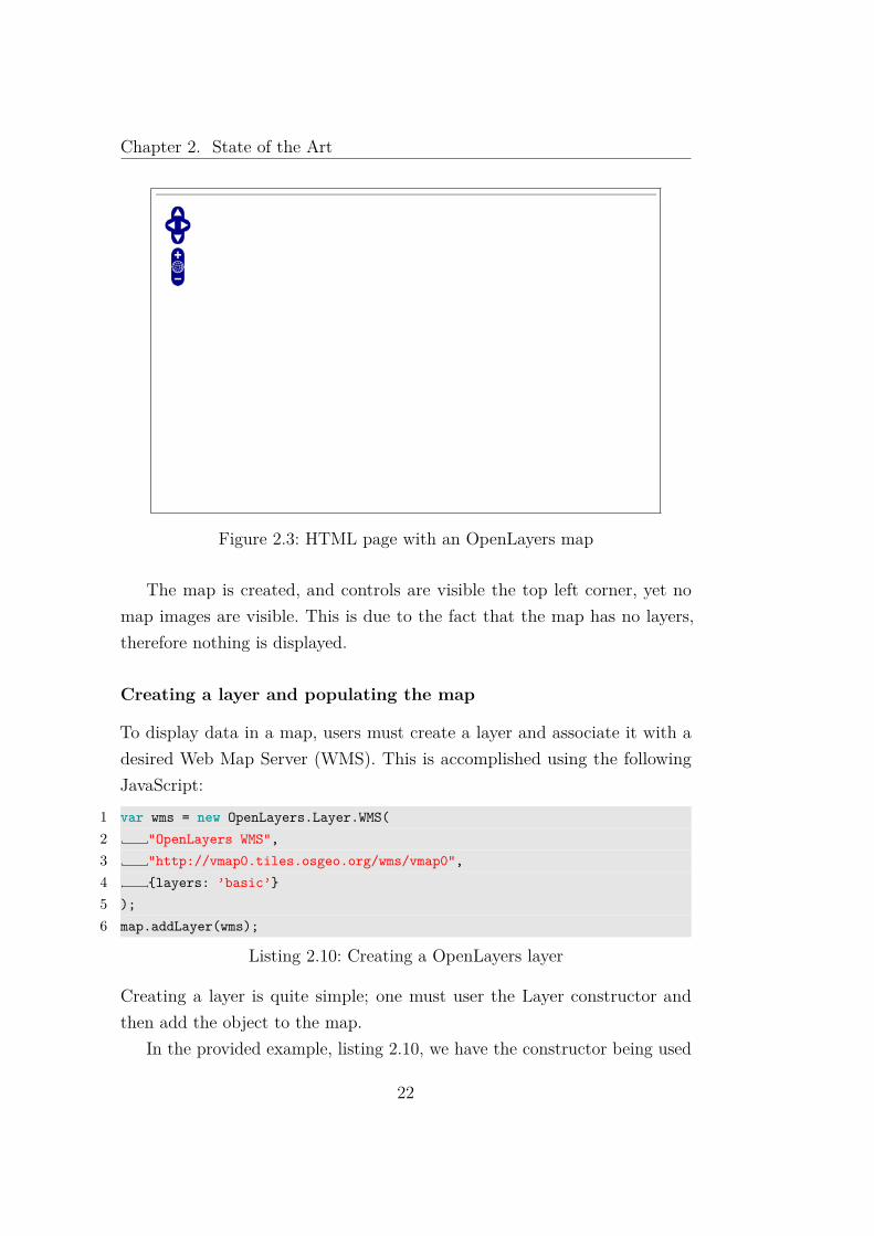
Figure 2.3: HTML page with an OpenLayers map
The map is created, and controls are visible the top left corner, yet nomap images are visible. This is due to the fact that the map has no layers,therefore nothing is displayed.
Creating a layer and populating the map
To display data in a map, users must create a layer and associate it with adesired Web Map Server (WMS). This is accomplished using the followingJavaScript:
1 var wms = new OpenLayers.Layer.WMS(2 "OpenLayers WMS",3 "http://vmap0.tiles.osgeo.org/wms/vmap0",4 {layers: ’basic’}5 );6 map.addLayer(wms);
Listing 2.10: Creating a OpenLayers layer
Creating a layer is quite simple; one must user the Layer constructor andthen add the object to the map.
In the provided example, listing 2.10, we have the constructor being used
22
Chapter 2. State of the Art
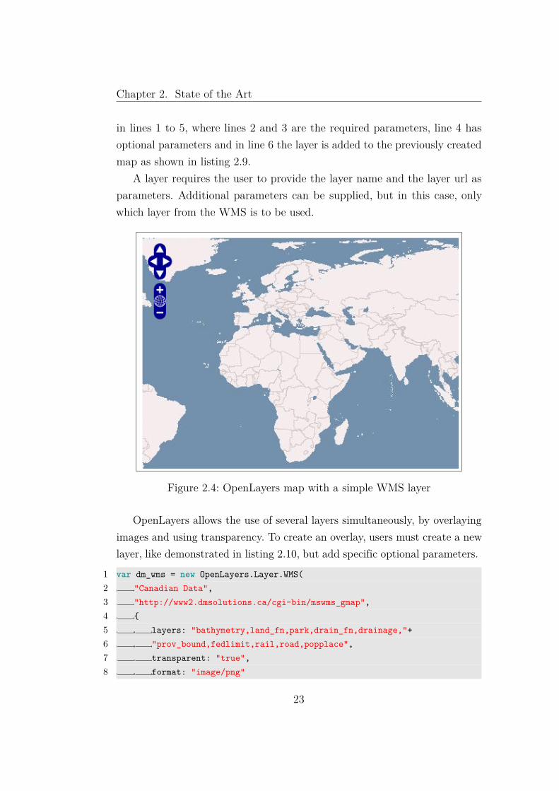
in lines 1 to 5, where lines 2 and 3 are the required parameters, line 4 hasoptional parameters and in line 6 the layer is added to the previously createdmap as shown in listing 2.9.
A layer requires the user to provide the layer name and the layer url asparameters. Additional parameters can be supplied, but in this case, onlywhich layer from the WMS is to be used.
Figure 2.4: OpenLayers map with a simple WMS layer
OpenLayers allows the use of several layers simultaneously, by overlayingimages and using transparency. To create an overlay, users must create a newlayer, like demonstrated in listing 2.10, but add specific optional parameters.
1 var dm_wms = new OpenLayers.Layer.WMS(2 "Canadian Data",3 "http://www2.dmsolutions.ca/cgi-bin/mswms_gmap",4 {5 layers: "bathymetry,land_fn,park,drain_fn,drainage,"+6 "prov_bound,fedlimit,rail,road,popplace",7 transparent: "true",8 format: "image/png"
23
Chapter 2. State of the Art
9 },10 {isBaseLayer: false}11 );12 map.addLayer(dm_wms);
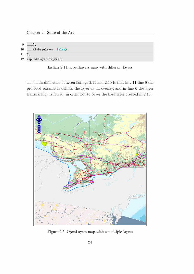
Listing 2.11: OpenLayers map with different layers
The main difference between listings 2.11 and 2.10 is that in 2.11 line 9 theprovided parameter defines the layer as an overlay, and in line 6 the layertransparency is forced, in order not to cover the base layer created in 2.10.
Figure 2.5: OpenLayers map with a multiple layers
24
Chapter 2. State of the Art
Controls and User Interface
OpenLayers adds default controls to the map, yet additional control elementscan be added for more interactivity. These can reside in the map or otherHTML elements present in the page.
1 map.addControl(new OpenLayers.Control.LayerSwitcher({’ascending’:false}));
Listing 2.12: Creating additional controls
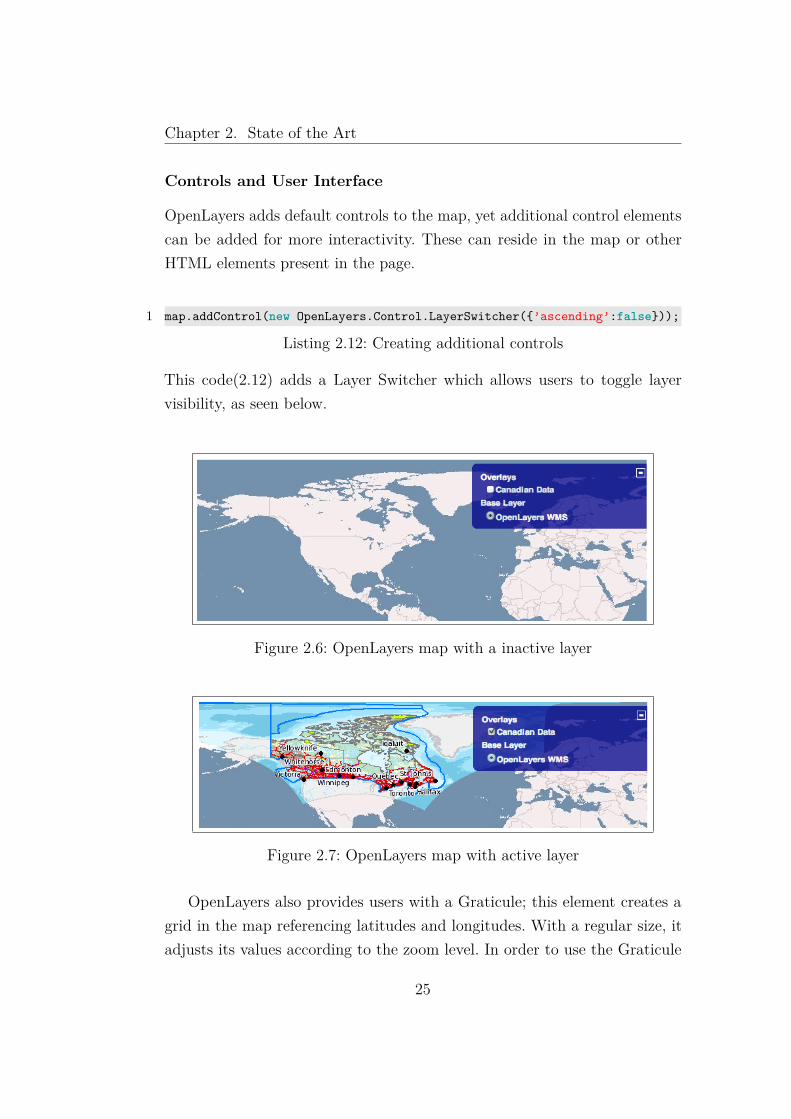
This code(2.12) adds a Layer Switcher which allows users to toggle layervisibility, as seen below.
Figure 2.6: OpenLayers map with a inactive layer
Figure 2.7: OpenLayers map with active layer
OpenLayers also provides users with a Graticule; this element creates agrid in the map referencing latitudes and longitudes. With a regular size, itadjusts its values according to the zoom level. In order to use the Graticule
25

Chapter 2. State of the Art
one uses the following JavaScript:
1 var grid = new OpenLayers.Control.Graticule({2 numPoints: 2,3 labelled: true4 });5 map.addControl(grid);
Listing 2.13: Creating a Graticule control
Figure 2.8: OpenLayers map with Graticule overlay
OpenLayers allows users to create text and points of interest. This is achievedby creating a TAB separated text file, in which one includes the point latitudeand longitude, the title, the description and the icon to be displayed.
1 var textPOI = new OpenLayers.Layer.Text( "text", {location: "./textfile.txt"} );
2 map.addLayer(textPOI);
Listing 2.14: Creating a Point of Interest with text
1 point title description icon2 10,20 my orange title my orange description3 2,4 my aqua title my aqua description4 42,-71 my purple title my purple description<br/>is great. http://www.
openlayers.org/api/img/zoom-world-mini.png
Listing 2.15: Textfile needed for creating a Point of Interest with text
26
Chapter 2. State of the Art
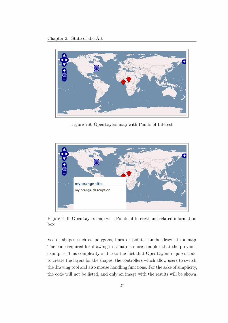
Figure 2.9: OpenLayers map with Points of Interest
Figure 2.10: OpenLayers map with Points of Interest and related informationbox
Vector shapes such as polygons, lines or points can be drawn in a map.The code required for drawing in a map is more complex that the previousexamples. This complexity is due to the fact that OpenLayers requires codeto create the layers for the shapes, the controllers which allow users to switchthe drawing tool and also mouse handling functions. For the sake of simplicity,the code will not be listed, and only an image with the results will be shown.
27

Chapter 2. State of the Art
Figure 2.11: OpenLayers map with vector shapes
2.5 WebGL Earth
WebGLEarth is a project that provides users with a three-dimensional globein the browser or mobile devices. According to the authors, there is supportfor the following functions:
• rotation and zoom of the globe
• camera tilt
• free movement in space
• support for existing maps like OpenStreetMap or Bing
• support for different layers or overlays like OpenLayers
• support for markers
• support for custom textures such as images from other planets
As requisites, WebGLEarth needs a browser that supports HTML5 canvasobject, the WebGL extension and JavaScript[1]. Creating a new scene inWebGL Earth is simple, just like in OpenLayers as shown in 2.4.1.
28
Chapter 2. State of the Art
1 <!DOCTYPE HTML>2 <html>3 <head>4 <script src="http://www.webglearth.com/api.js"></script>5 <script>6 function initialize() {7 var options = { zoom: 3, position: [47.19537,8.524404], proxyHost:
’http://data.webglearth.com/cgi-bin/corsproxy.fcgi?url=’ };8 var earth = new WebGLEarth(’earth_div’, options);9 }
1011 </head>12 <body onload="initialize()">13 <h1>WebGL Earth API: Hello World</h1>14 <div id="earth_div" style="width:600px;height:400px;border:1px solid
gray; padding:2px;"></div>15 </body>16 </html>
Listing 2.16: Creating a WebGL Earth globe
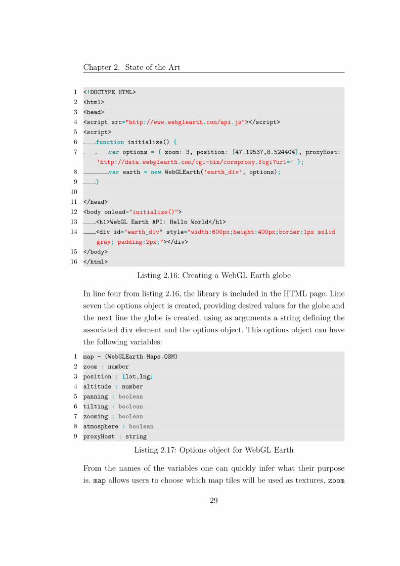
In line four from listing 2.16, the library is included in the HTML page. Lineseven the options object is created, providing desired values for the globe andthe next line the globe is created, using as arguments a string defining theassociated div element and the options object. This options object can havethe following variables:
1 map - (WebGLEarth.Maps.OSM)2 zoom : number3 position : [lat,lng]4 altitude : number5 panning : boolean6 tilting : boolean7 zooming : boolean8 atmosphere : boolean9 proxyHost : string
Listing 2.17: Options object for WebGL Earth
From the names of the variables one can quickly infer what their purposeis. map allows users to choose which map tiles will be used as textures, zoom
29

Chapter 2. State of the Art
is the zoom level for the tiles, position is a vector containing latitude andlongitude for the camera, altitude is the camera altitude in meters. panning,tilting, zooming and atmosphere are boolean values which enable or disablethe function with the same name. proxyHost allows users to define a proxy.
WebGL Earth despite using 3D, is only a globe and the maps are displayedas textures, as can be seen in image 2.12. When zooming close to the surface,there is no sense of height. Since there are no digital elevation models, thenotion of the globe disappears when the camera gets close to the surface, thevisualization appears two dimensional, just like the one fond in OpenLayersand image 2.13.
Figure 2.12: WebGL Earth globe
30

Chapter 2. State of the Art
Figure 2.13: WebGL Earth globe zoomed in
2.6 Web 3D Service
W3DS is a service for three-dimensional geodata such as digital elevationmodels, city and building models, vegetation and street furniture.
The purpose of W3DS is much like that of WMS, yet while the later sup-plies attributes and semantic information as well as images, W3DS purposeis to provide scene graphs consisting of a tree like structure of nodes, groups,transforms, shapes, materials, and geometries. In order to obtain attributeslike those found on WMS, users rely on the GetFeatureInfo provided byW3DS. The data format supported by W3DS is X3D, since this is a WorldWide Web Consortium (W3C) standard. The level of detail for the providedgeometry goes from highly detailed 3D models to prototype-like structures,
31

Chapter 2. State of the Art
enabling a controlled performance and keeping the geometry detail to theminimum needed.
TheW3DS API has five different operations; GetCapabilities, GetScene,GetTile, GetLayerInfo, GetFeatureInfo. From those, only the first two aremandatory, being the remaining optional.
All operations have parameters, and the following are mandatory andcommon to every request:
SERVICE Service identifier (W3DS).
REQUEST Request identifier (GetCapabilities or GetScene).
VERSION The version of the operation to be used.
2.6.1 GetCapabilities
This operation allows users to know which resources are available in the server.The reply is a XML which contains metadata about the server and the owner.Also in the reply is information of available operations and a description ofall data present in the server. This description usually contains a list of layersavailable and, for each layer, a list of their properties, like the coordinatesystem, the size, styles, if it is tiled or if there are different Level of Detail(LOD).
2.6.2 GetScene
Using the GetScene request, users can obtain 3D data from the server. Asparameters for the request, the following are mandatory; CRS which is thecoordinate system being used, BoundingBox which defines the rectangle en-compassing the dataset, Format provides the server with the required outputformat for the 3D data, most commonly the X3D file format .Layer informsthe server of which layers are to be included in the dataset.
32

Chapter 2. State of the Art
2.6.3 GetTile
Since X3DOM allows adding geometry data during runtime, and the data inthe server can be quite large, there is sectioned data. These are called tilesand cannot be accessed by the GetScene request.The GetTile request allows users to select specific tiles contained in the serverand the request has the following mandatory parameters; CRS, Layer andFormat just like the GetScene request as well as TileLevel which defines thedesired LOD for the tile, TileRow which is the row of the tile and TileColis the column.
2.6.4 GetLayerInfo
Layers have information about their attributes, and through the use of thisrequest, it is possible to obtain a XML document with the attributes of aspecified layer.
2.6.5 GetFeatureInfo
This request allows one to obtain information about features of a element con-tained in a layer. Making a GetFeatureInfo request requires four mandatoryparameters; CRS, Layers, Format and Coordinates. CRS is the coordinatesystem used, Layers is a list of layers the user is requesting information from,Format is the reply format and Coordinates as the name implies is a pair ofcoordinates used to search for the features.
33

Chapter 2. State of the Art
34

Chapter 3
Implementation
3.1 JavaScript Object and Initial Requirements
Before starting the development stage, one must define the requirements thelibrary must meet. In order to use the library, users should have a HTML5compatible browser, as well as the X3DOM library and jQuery.
X3DOM as previously stated in section 2.3, is the bridge between thebrowser and X3D. jQuery is a JavaScript library that intends to simplifyHTML document traversing and facilitate AJAX operations.
As for the OL3 library, it must fulfill the following requisites in order tobe a fully functional prototype.
• asynchronous communication with the server
• have the ability to make a GetCapabilities request and obtain theinformation contained in the response
• implement a Bounding Box
• have a controlable camera and be aware of the camera’s position androtation
• be able to calculate the viewing frustrum
• the ability to differentiate layers
35

Chapter 3. Implementation
• capable of managing tiles of needed geometry
3.1.1 Object Oriented Programming in JavaScript andthe OL3 Object
When developing in JavaScript one must retain the following premises; inJavaScript everything is an object and the use of name spacing avoids collisionwith other libraries.
Since it is a prototype-based language, to create new objects one justclones other objects. Using function someFunction() {}; is exactly thesame as var someFunction = function(){};. This newly created functionis also an object and can be added as a property of some other pre-existingobject.
When using code with other JavaScript libraries it is recommended the useof namespaces. This will allow for lower naming collision with other librariesand create unique groups that can be better organized and managed.
The namespace creation function guarantees that a single object with thatname is created, so when one tries to create a namespace that already exists,an error will be thrown. The namespace chosen was OL3.
The selected namespace is then created and a Class function is added tothe object. This function intends to implement a construct similar to thosepresent in Java or C++. All the other classes implemented as a part of theOL3 object are then created using the OL3 namespace and implement thisClass definition. This will guarantee a more organized and easier to maintainstructure.
1 OL3.Class = function(2 // Class definition object: mandatory3 __proto__4 ) {5 var Class = __proto__.hasOwnProperty("initialize") ?6 // use it ...7 __proto__.initialize :8 // otherwise create one and assign it9 (__proto__.initialize = function () {})
36

Chapter 3. Implementation
10 ;11 Class.prototype = __proto__;12 return Class;13 };
Listing 3.1: Class implementation
The Class function of the OL3 object checks if a newly created object hasa initialize function; if so it will use it as a constructor, otherwise it willcreate an empty one.
To define a new class, one would do the following:1 OL3.Person = new OL3.Class(2 {3 initialize : function (name)4 {5 this.name = name;6 }7 sayName : function()8 {9 alert(this.name);
10 }11 });
Listing 3.2: New class definition
To create a new instance of the Person class, all one needs to do is assign avariable with the Person object.
1 var Human = new OL3.Person("John Doe");
Listing 3.3: Instantiating a new Person Object
Having the namespace and the Class function implemented, the next stepwas the creation of objects that allowed connection to the server, obtaininginformation about the data present in the server and objects that representedthe main structures needed; the Scene, the Camera and the Layer.
3.1.2 Asynchronous Communication with the Web Server
JavaScript supports asynchronous communications with web servers. Gath-ering information and 3D data from a server is a common operation and so
37

Chapter 3. Implementation
an object to perform these tasks with a web server was created. This object,named OL3.XMLHTTPRequest, uses the XMLHttpRequest (XHR) API tosend Hypertext Transfer Protocol (HTTP) requests to the server and loadthe data contained in the response back to the scripts.
Any object which requires data to be loaded from the web server has afunction called getReply that is used by the OL3.XMLHTTPRequest objectwhen the data has been loaded successfully. The object’s getReply functionwill act to what has been returned from the server and then, accordingly tothe required action, will parse and use the information, being this about alayer or 3D data contained in the web server.
The OL3.XMLHTTPRequest implementation relies on the jQuery librarysince it simplifies the use of XHR.
1 var jqxhr = $.ajax( urlRequest )2 .done3 (4 function()5 {6 var reply = jqxhr.responseText;7 parent.getReply(reply);8 }9 )
10 .fail11 (12 function()13 {14 throw new Error("Error obtaining data from server");15 }16 );
Listing 3.4: Example of XMLHttpRequest using jQuery
jQuery makes the implementation quite fast and simple, as can be seen inthe listing 3.4. This listing represents more than 50% of the code required tocreate the OL3.XMLHTTPRequest object.
In line 6, the variable reply contains the data from the web server, and inline 7, the getReply method from the object which made a request is beingsupplied with the results. These are always XML files, which the object will
38

Chapter 3. Implementation
parse and create the necessary structures.
3.1.3 GetCapabilities
The OL3 implements a GetCapabilities request. By sending this request, aclient can obtain information about a W3DS server, such as available data,supported formats among others.
Using the following Uniform Resource Locator (URL), one can make acapabilities request to a W3DS server.[7]http://3dwebgis.di.uminho.pt/geoserver3D/w3ds?VERSION=0.4.0&SERVICE=w3ds&REQUEST=GetCapabilities
The request is made using AJAX, and relies on the OL3.XMLHTTPRequestclass. The reply is a XML file containing all the information relative to theserver. The information a GetCapabilities reply gives consists of the followingitems; services supported, formats supported, spatial reference systems, listof map layers, SLD/Styles and vendor specific codes.
1 <ows:Operation name="GetScene">2 <ows:DCP>3 <ows:HTTP>4 <ows:Get xlink:href="http://3dwebgis.di.uminho.pt/geoserver3D/
w3ds?">5 <ows:Constraint name="GetEncoding">6 <ows:AllowedValues>7 <ows:Value>KVP</ows:Value>8 </ows:AllowedValues>9 </ows:Constraint>
10 </ows:Get>11 </ows:HTTP>12 </ows:DCP>13 </ows:Operation>
Listing 3.5: Example of a GetCapabilities reply describing a get scene request
Each time a layer is created, there is a new OL3.Capabilities object createdwhich is part of the layer object. Using a string containing the W3DS URLand a string defining a name for the layer, the OL3.Capabilities object will
39

Chapter 3. Implementation
parse the reply XML obtained from the W3DS. From the data received, theobject will try to check if a layer with the name the user provided exists. Iffound, the layer properties will be parsed and returned to the new layer. Ifno information is found for the layer name requested, the new layer will notbe created.
Since the OL3.Capabilities object will communicate with the server, thisobject possesses a getReply function.
This function will check if the reply from the W3DS server is a valid oneor an exception has occurred. In case the response is valid, then it proceedsto find requested layer. When the layer is found, the OL3.Capabilities parserswill obtain all the properties of the layer, such as the Coordinate ReferenceSystem (CRS), the styles, the different LODs and if the layer is tiled or not.These properties will then be sent back to the layer object and a new layer isavailable to the user.
3.1.4 Bounding Box
"The bounding box is the computationally simplest of all linearbounding containers, and the one most frequently used in manyapplications." [9]
Inheriting from the geographic information metadata standard ISO 19115Metadata Standard, this object represents the maximum extents of a twodimensional object in a 2D coordinate system, being represented by a fourvalue pair of min(x), max(x), min(y) and max(y). These values must fullyenclose the object and the rectangle faces must be aligned with the axes of aCartesian coordinate system.
The Bounding Box class is a structure that contains the two delimitingpoints of a layer, these being the lower left corner and the upper right corner.In geospatial data, these serve as an approximation for the areal coverage ofthe feature.[4]
The OL3 bounding box object contains an array with the four valuesdelimiting the rectangle.
lowercorner1 this value is the equivalent to min(x)
40

Chapter 3. Implementation
lowercorner2 this value is the equivalent to min(z)
uppercorner1 this value is the equivalent to max(x)
uppercorner2 this value is the equivalent to max(z)
Besides the rectangle values, there is a CRS variable, so that there is a refer-ence to the coordinate system being used.
This being a library which allows navigation in 3D, one would assumethat the bounding box would be in 3D, with x, y and z axis, yet the valuesreturned by the W3DS only contain two axis (x and z).
Following is a description of the 3D bounding box implementation com-pared with the W3DS implementation.
Figure 3.1: 3D Bounding box (left) and current implementation (right)
As can be seen in image 3.1, on the left side there is a 3D boundingbox and on the right is the current implementation. The light green shaperepresents the y = 0 plane which intersects two cylinders. The 3D bounding
41
Chapter 3. Implementation
box containing the left cylinder is a blue cube which can be defined withpoints p1x,y,z and p2x,y,z. Using the current implementation, shown on theright, there is only p3x,z and p4x,z. With these vales one can only define arectangle, that when changed into 3D would represent all objects containedinside a parallelogram extending into −∞ and +∞ in the y axis.
Since geographical data is quite uniform vertically, the need for a 3Dbounding box is not that relevant and is open for discussion. W3DS is onlythe source for 3D data used by OL3, the bounding box implementation inthe server is irrelevant, and OL3 must use that implementation.
3.2 OL3 Structures
3.2.1 Scene
The Scene is a top-level object and acts as a container which allows childrenobjects to interact with each other. It contains a Camera object and a Layerobjects array. The Camera object will allow the different objects within thescene to access the camera properties and the Layer array will contain alllayers associated with the scene.
The scene initialization is quite similar to the one used in OpenLayers, asdemonstrated in 2.8. The user creates a div element in the HTML documentwhich will contain the scene, and then he must initialize the scene by usingthe following function:
1 var scene = new OL3.Scene(bb, options);
Listing 3.6: Creating a Scene
As seen in the example listing 3.6, one creates an scene object as a variable.The bb argument provided is a Bounding Box, which is mandatory, but yet ofno use. As for the options variable, it is an object which contains propertiesfor the scene. This last object is not mandatory, for the Scene object hasdefault values, as shown in listing 3.7.
1 var default_args =
42

Chapter 3. Implementation
2 {3 ’div’ :"#map",4 ’width’ :450,5 ’height’:450,6 ’stat’ :false,7 ’log’ :false8 };
Listing 3.7: Scene default variables
The default arguments represent the following:
div This string is the id of the div element in which the user intends toplace the scene.
width / height These variables represent the width and height of the ren-dering window for the X3DOM object, which will then be placed insidethe div element.
stat / log These two boolean variables are here to allow users to turn ondebug information regarding the X3DOM object.
When a scene is created, the HTML DOM is changed and X3D nodes areinserted. These nodes are an empty X3D scene without any geometry nodes,and the scene-graph resembles the one described in 11.
Inside the scene node there is a transform node, whose id is named "en-trada".The node serves as an entry point where all 3D elements will be added.Through this method one can identify clearly which elements of the scene-graph are part of the initial scene, those outside the transform node, and theones added later, inside the transform node.
3.2.2 Camera Implementation
In order to allow interaction for the scene navigation, several implementationsof camera movement were studied. The main purpose of this study was toallow the end-user to move the camera in the scene and the library alwaysbeing aware of the camera position and rotation. Through this constantmonitoring, it was also intended to have a notion of what geometry was seen
43
Chapter 3. Implementation
by the camera.Three different implementations were studied; one which the user could
move the camera with buttons present in the HTML, the second approachwas standard X3DOM camera movement with the mouse and calculatingthe viewing frustum, and finally using the same method as the previous, yetinstead of calculating the viewing frustum, rays are emitted from the fourcorners of the camera and then calculating where they would intersect theground plane. A more detailed description is given below.
HTML buttons
This approach uses four transform nodes just below the scene root node andHTML button elements to control transformations applied to the scene-graph.
The transform nodes are a translation node, to change the scene transla-tion in the x, y and z axis, as well as three rotation nodes, one for each axisof rotation. All the 3D elements will be placed inside these nodes, in order tobe affected by their transformation. By changing the values of the transformnodes, one can change the scene in relation to the camera position.
This is the approach with the easier implementation, yet there is a minorsetback, as there is no simple method to calculate what geometry is withinthe camera view port.
Viewing Frustum
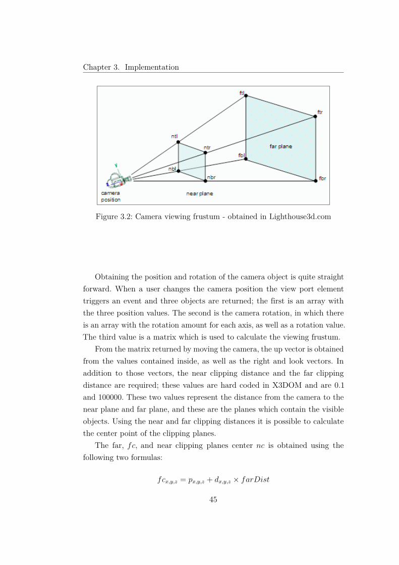
The viewing frustum[5] is a volume in the modeling world where all thevisible objects reside, although some occlusions may occur. This volume hasthe shape of a truncated pyramid when using a perspective projection, wherethe apex resides in the camera position and the base in the far clipping plane.The near clipping plane truncates the top of the pyramid, thus calling thevolume a frustum.
The camera controls in this implementation rely on mouse interactionswith the canvas element. All changes to the scene and the camera are handledby X3DOM, therefore to have the camera position and rotation as well aswhat geometry is visible, one must obtain those values from X3DOM.
44
Chapter 3. Implementation
Figure 3.2: Camera viewing frustum - obtained in Lighthouse3d.com
Obtaining the position and rotation of the camera object is quite straightforward. When a user changes the camera position the view port elementtriggers an event and three objects are returned; the first is an array withthe three position values. The second is the camera rotation, in which thereis an array with the rotation amount for each axis, as well as a rotation value.The third value is a matrix which is used to calculate the viewing frustum.
From the matrix returned by moving the camera, the up vector is obtainedfrom the values contained inside, as well as the right and look vectors. Inaddition to those vectors, the near clipping distance and the far clippingdistance are required; these values are hard coded in X3DOM and are 0.1and 100000. These two values represent the distance from the camera to thenear plane and far plane, and these are the planes which contain the visibleobjects. Using the near and far clipping distances it is possible to calculatethe center point of the clipping planes.
The far, fc, and near clipping planes center nc is obtained using thefollowing two formulas:
fcx,y,z = px,y,z + dx,y,z × farDist
45
Chapter 3. Implementation
ncx,y,z = px,y,z + dx,y,z × nearDist
Where p is the camera position, d is a normalized vector with the directionof the camera’s viewing ray, farDist is the far clipping distance and nearDist
is the near clipping distance.Using the field of view, which is obtained from the X3DOM viewpoint
object, the aspect ratio and the clipping distances, one can obtain the thewidth and the height of the near and far planes.
Height of near plane
Hnear = 2× tan(fov/2)× nearDist
Where fov is the field of view and nearDist is the near clipping distance.
Width of near plane
Wnear = Hnear × ratio
Using the height of the near plane Hnear calculated previously, multi-plying it with the value of the aspect ratio ratio one obtains the widthof the near plane.
Height of far plane
Hfar = 2× tan(fov/2)× farDist
With the field of view fov and the far clipping plane distance, farDist,the height of the far plane is obtained.
Width of far planeWfar = Hfar × ratio
As for the width of the far clipping plane, it can be calculated usingthe height of the far plane, Hfar, and the aspect ratio ratio.
46

Chapter 3. Implementation
From the values calculated with the previous formulas, the only remainingstep to obtain the viewing frustum is to know the values of the four pointsdefining the corners of the near and far clipping planes.
To determine the far clipping plane corners, one must use the followingfunctions:
ftlx,y,z = fcx,y,z + (upx,y,z ×Hfar/2)− (rightx,y,z ×Wfar/2)
ftrx,y,z = fcx,y,z + (upx,y,z ×Hfar/2) + (rightx,y,z ×Wfar/2)
fblx,y,z = fcx,y,z − (upx,y,z ×Hfar/2)− (rightx,y,z ×Wfar/2)
fbrx,y,z = fcx,y,z − (upx,y,z ×Hfar/2) + (rightx,y,z ×Wfar/2)
Where ftl is the far top left corner, ftr is the far top right corner, fbl thefar bottom left corner and fbr the far bottom right corner of the plane. fc isthe far clipping plane center, up is the up vector and right the right vector.The Wfar stands for width of the far clipping plane and Hfar the height ofthe far clipping plane.
The same functions can be used to determine the corners of the nearclipping plane, ntl, ntr, nbl and nbr. One still uses the up and right vectors,up and right, but instead of the width and height of the far clipping plane,the width and height of the near clipping plane are used, Hnear and Wnear.
ntlx,y,z = ncx,y,z + (upx,y,z ×Hnear/2)− (rightx,y,z ×Wnear/2)
47

Chapter 3. Implementation
ntrx,y,z = ncx,y,z + (upx,y,z ×Hnear/2) + (rightx,y,z ×Wnear/2)
nblx,y,z = ncx,y,z − (upx,y,z ×Hnear/2)− (rightx,y,z ×Wnear/2)
nbrx,y,z = ncx,y,z − (upx,y,z ×Hnear/2) + (rightx,y,z ×Wnear/2)
Ray Emission
Using the previously described approach of the viewing frustum as a startingpoint, there is another solution to obtaining the four edges defining the sidesof the truncated pyramid. X3DOM allows users to emit rays at specific pointsin the view port. These rays will return a normalized vector with a directionin the form of a X3DOM Line object, comprised of a starting position anda direction. If one emits four rays, one at each view port corner, the resultwould be the direction of the four edges defining the pyramid sides of theviewing frustum.
To emit a ray at a given position the following method is used:
1 var line = viewarea.calcViewRay(x, y);
Listing 3.8: Emitting a ray
In this approach there is no need to calculate the viewing frustum and theclipping planes, only the edges of the pyramid. This is done because of theintersection with the y = 0 plane. This intersection is detailed in the followingsubsection.
48
Chapter 3. Implementation
y = 0 plane intersection
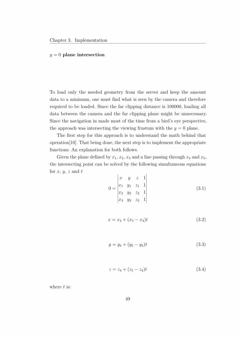
To load only the needed geometry from the server and keep the amountdata to a minimum, one must find what is seen by the camera and thereforerequired to be loaded. Since the far clipping distance is 100000, loading alldata between the camera and the far clipping plane might be unnecessary.Since the navigation in made most of the time from a bird’s eye perspective,the approach was intersecting the viewing frustum with the y = 0 plane.
The first step for this approach is to understand the math behind thatoperation[10]. That being done, the next step is to implement the appropriatefunctions. An explanation for both follows.
Given the plane defined by x1, x2, x3 and a line passing through x4 and x5,the intersecting point can be solved by the following simultaneous equationsfor x, y, z and t
0 =
∣∣∣∣∣∣∣∣∣∣∣∣
x y z 1x1 y1 z1 1x2 y2 z2 1x3 y3 z3 1
∣∣∣∣∣∣∣∣∣∣∣∣(3.1)
x = x4 + (x5 − x4)t (3.2)
y = y4 + (y5 − y4)t (3.3)
z = z4 + (z5 − z4)t (3.4)
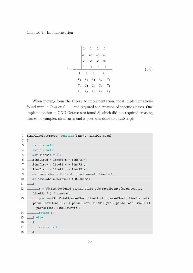
where t is:
49
Chapter 3. Implementation
t = −
∣∣∣∣∣∣∣∣∣∣∣∣
1 1 1 1x1 x2 x3 x4
y1 y2 y3 y4
z1 z2 z3 z4
∣∣∣∣∣∣∣∣∣∣∣∣∣∣∣∣∣∣∣∣∣∣∣∣
1 1 1 0x1 x2 x3 x5 − x4
y1 y2 y3 y5 − y4
z1 z2 z3 z5 − z4
∣∣∣∣∣∣∣∣∣∣∣∣
′ (3.5)
When moving from the theory to implementation, most implementationsfound were in Java or C++, and required the creation of specific classes. Oneimplementation in GNU Octave was found[8] which did not required creatingclasses or complex structures and a port was done to JavaScript.
1 linePlaneIntersect: function(lineP1, lineP2, quad)2 {3 var t = null;4 var p = null;5 var lineDir = {};6 lineDir.x = lineP1.x - lineP2.x;7 lineDir.y = lineP1.y - lineP2.y;8 lineDir.z = lineP1.z - lineP2.z;9 var numerator = Utils.dot(quad.normal, lineDir);
10 if(Math.abs(numerator) > 0.000001)11 {12 t = (Utils.dot(quad.normal,Utils.subtract2Points(quad.point1,
lineP1) ) ) / numerator;13 p = new OL3.Point(parseFloat(lineP1.x) + parseFloat( lineDir.x*t),
parseFloat(lineP1.y) + parseFloat( lineDir.y*t), parseFloat(lineP1.z)+ parseFloat( lineDir.z*t));
14 return p;15 } else16 {17 return null;18 }
50

Chapter 3. Implementation
19 },
Listing 3.9: Intersection of a plane with a line function
The function linePlaneIntersect takes as arguments two points crossed bythe line lineP1 and lineP2 and a plane quad. This plane object besides fourpoints contains a normal, which will be used to calculate the intersection. Ifthe dot product of the plane’s normal and the lineDir is of significant value,as seen in line 9 of listing 3.9, then there is an intersection and that point,p, is calculated. Besides calculating the point of intersection, the functionalso provides t, which can be used to check if the intersection is containedbetween the two points lineP1 and lineP2.
Using either the Viewing Frustum approach described in 3.2.2 or the Rayemission method described in 3.2.2 one can obtain the four lines that containall objects visible by the camera. Intersecting those lines with the y = 0plane, the four points that create the bounding box of the visible objects arecalculated. Using this bounding box it’s just a matter of asking the server forgeometry inside those points to obtain all the data needed.
Comparison between the different approaches
The HTML buttons method as a user interface does what is required, asit allows a controlled navigation. Although a controlled navigation is goodfor inexperienced users, as it avoids getting lost, it doesn’t work well withlarge amounts of data as the library cannot calculate the bounds of cameravisibility.
When using the viewing frustum the navigation is smoother yet moreunrestrained, therefore inexperienced users can get lost navigating the scene.This approach however, does allow the library to calculate the visible objects,making this optimal for large amounts of data that need to be gathered fromthe server when needed. This implementation had a error, as there were issueswhen changing the camera and obtaining the points of intersection in they = 0 plane. These where swapped on some axis and when swiveling thecamera the geometry requested from the server was wrong. Due to this errorthe Ray emission was found as a viable solution.
51

Chapter 3. Implementation
The ray emission approach allows users to experience the same smoothand unrestrained navigation as the viewing frustum implementation, but sincethe amount of functions required to obtain the four points is considerablysmaller and the library produces no errors calculating the intersection pointswhen the camera swivels, this is the current method used by the Cameraclass.
3.2.3 Layer
Just like in OpenLayers different geographical information has different layers,so OL3 borrows the layers concept in order to separate different geometryinformation.
As an example, if one should have terrain data, buildings and sewage linesin a scene, one would separate the terrain, the buildings and the sewage indifferent layers. This separation will benefit the library as a more adequatemethod of controlling the geometry information in the scene graph and toallow easier access and perform changes in specific geometry groups. Thisseparation also allows users to request only what they wish to load, since theycould be interested in only parts of the geometry contained in the W3DSserver, say for example only the buildings and sewage lines, but no terrain.
Each time a Layer is created, the Scene object adds the new Layer to anarray. This is done so users or other objects can access any layer containedthe scene.
1 var buildings = new OL3.Layer(parent,urlEntry, nameLayerEntry);
Listing 3.10: Creating a new Layer
Creating a Layer is a straight-forward process, using the constructor andsupplying a scene which will contain the Layer, parent, a URL for the W3DSserver, urlEntry, and the last parameter is the name of the layer as containedin the web server, nameLayerEntry.
When instantiating a new Layer, the object will use the Ol3.Capabilitiesclass to check if it is a valid layer. This is done so that the layer can have avalid W3DS URL and a valid name. This valid name implies that the nameof the layer must be the same as a layer name in the W3DS server being used.
52
Chapter 3. Implementation
Doing so ensures that the layer will have available data in the server to beshown to the users.
If there is no such layer in the W3DS server, the Layer object will not beadded to the scene, avoiding later requests for non-existent geometry datafrom the server.
Obtaining geometry data from a server
A Layer is responsible for obtaining geometry data from the server and dis-playing it to the users. In the server one can find two types of layers; the firstbeing untiled models and the second tiled geometry. When creating a layer,at the time the capabilities file is parsed, there is information whether thelayer is tiled or not. This is reflected in a property of the layer object, andtherefore, when making requests for geometry one needs to differentiate therequests. If the layer is not tiled the GetScene request is used, as describedin page 32, otherwise the GetTile request is used as seen in page 33.
Making a request to the W3DS server for geometry is made just likethe Capabilities request; a OL3.XMLHTTPRequest is created providing theserver with the required data, and then the server returns the X3D file asyn-chronously. As soon as the server makes the data available to the layer object,the X3D file is parsed and the nodes are inserted in the DOM. Although thegeometry comes in the same format, X3D, the approaches to deciding whichdata is requested from the server are different.
Loading a untiled model, the layer makes a request to the server for thegeometry and when the data is received, the X3D nodes are parsed and theninserted into the scene-graph entry point of the HTML DOM.
Tiled geometry requires a different approach than the one used for untiledmodels. Tiled geometry is used for large amounts of data, which makes it cum-bersome to load in a single request. To avoid this setback, this data is dividedin square tiles. The W3DS server allows users to request tiles according to agrid position. This grid depends on the bounding box of the geometry andthe level of detail desired. When creating a layer, the tile sizes are obtainedfrom the GetCapabilities response, and then the layer object will create a
53

Chapter 3. Implementation
Figure 3.3: Loaded geometry for a untiled model using a GetScene request
structure to contain the grid information. This structure is an array whoselength is dependent of the different LODs available. In each item of the arrayis stored a two-dimensional array of tiles, reflecting a grid of tiles present inthe server for the respective LOD.
Tiles and the Grid
Tiled geometry is obtained using a GetTile request from a W3DS server. OL3layers can either have untiled or tiled geometry. Layers with tiled geometrypossess a grid array, where grids are created and stored according to thenumber of LODs present in the server for the specified layer.
For each level of detail, there is a specific tile size and using the tile sizeand the layer’s bounding box, the amount of rows and columns composingthe grid are calculated.
1 this.numberColumns = Math.floor(width/tilesize);2 this.numberRows = Math.floor(height/tilesize);
Listing 3.11: Calculating the grid’s columns and rows
54

Chapter 3. Implementation
Figure 3.4: Loaded geometry for a untiled model using a GetScene requestand tiled geometry using a GetTile request
The used W3DS server had exponential tile sizes, and the grid array structurecan be represented graphically as seen in figure 3.5. The smaller the squareis, the bigger the LOD.
Figure 3.5: Grid representation
Each grid contained in the array is itself a two-dimensional array, withits size given by the number of columns and rows present in the grid. Eachelement of that array is a tile.
The Tile object is a OL3 class that allows the library to check if the tilehas been requested from the server or if the tile is loaded in the scene. These
55

Chapter 3. Implementation
will help reduce the amount of data loaded as no repeated geometry will berequested. It is also possible to check the tile’s lower corner, the row, columnand also the midpoint. Using both the grid and the tiles, loading the necessarygeometry from the server is simplified. With the method described in page 49,the library will build a temporary grid to decide which geometry is required.
Figure 3.6: Temporary Grid construction
Starting with figure 3.6 as a reference, the first grid is the one with ahigher LOD and the last grid is the one with the lowest LOD.
The temporary grid is built in the following way; first the camera position
56
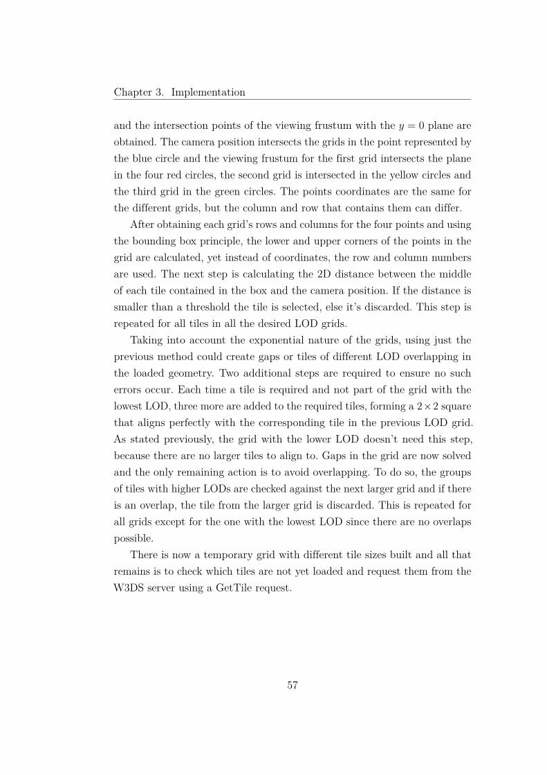
Chapter 3. Implementation
and the intersection points of the viewing frustum with the y = 0 plane areobtained. The camera position intersects the grids in the point represented bythe blue circle and the viewing frustum for the first grid intersects the planein the four red circles, the second grid is intersected in the yellow circles andthe third grid in the green circles. The points coordinates are the same forthe different grids, but the column and row that contains them can differ.
After obtaining each grid’s rows and columns for the four points and usingthe bounding box principle, the lower and upper corners of the points in thegrid are calculated, yet instead of coordinates, the row and column numbersare used. The next step is calculating the 2D distance between the middleof each tile contained in the box and the camera position. If the distance issmaller than a threshold the tile is selected, else it’s discarded. This step isrepeated for all tiles in all the desired LOD grids.
Taking into account the exponential nature of the grids, using just theprevious method could create gaps or tiles of different LOD overlapping inthe loaded geometry. Two additional steps are required to ensure no sucherrors occur. Each time a tile is required and not part of the grid with thelowest LOD, three more are added to the required tiles, forming a 2×2 squarethat aligns perfectly with the corresponding tile in the previous LOD grid.As stated previously, the grid with the lower LOD doesn’t need this step,because there are no larger tiles to align to. Gaps in the grid are now solvedand the only remaining action is to avoid overlapping. To do so, the groupsof tiles with higher LODs are checked against the next larger grid and if thereis an overlap, the tile from the larger grid is discarded. This is repeated forall grids except for the one with the lowest LOD since there are no overlapspossible.
There is now a temporary grid with different tile sizes built and all thatremains is to check which tiles are not yet loaded and request them from theW3DS server using a GetTile request.
57
Chapter 3. Implementation
Figure 3.7: Temporary Grid layout
Image 3.7 represent the completed temporary grid. The green cube rep-resents the camera and the blue dot on the grid is the camera position inthe grid. The red dots represent the four points where the camera viewingfrustum intersects the y = 0 plane. The tiles are loaded in sets of four andthe grid is now built with several LOD and no gaps or overlaps. Tiles that falloutside the viewable area are not loaded, therefore no extra data was usedfrom the W3DS server.
58

Chapter 4
OL3 in Action
In the previous chapter we described the implementation of the OL3 library,focusing on specific algorithms that were needed to handle the specific re-quirement of 3D data.
In this chapter, we will show how to get the existing code, how to set upand run a simple web page with a very basic map and finally, we show howto contribute to the OL3 implementation by sending pull requests.
4.1 Manage code development using Git
When several developers are working on the same project, code managementtools are required to manage all contributions. These tools allow multipleusers contributing to the code without overwriting, by accident, other con-tributions made by the different elements involved in the project. Also thereis the possibility to track the complete history of the project’s development,and what changes were made during the development process and by whom.The history capabilities of code management tools are a good provider of in-formation to be included in the release notes, informing users of the changesmade since the previous version.
We are using the Bitbucket online git repository to store our project.
59
Chapter 4. OL3 in Action
4.1.1 Complementary code management tools
Besides code versioning and management, the online repository offers arecomplementary tools like viewing source code, commit history as well as issuetracking and wiki.
Issue tracking is a powerful tool for developers, since all involved in theproject as well as users can submit issues found either when developing or usingthe software. These issues can then be ranked according to their importance,marking more serious errors as more important issues and therefore givingthem more prominence over others. Issues can also be delegated to specificusers or teams, avoiding redundant work by other developers.
The wiki provided by the repository allows the developers to create guidesto help users getting started using the library, by providing tutorials, aswell as create guides to explain other developers how they can help in thedevelopment, by explaining how the library is structured and how to createadditional functions and objects.
4.2 How to get OL3 code
Downloading the existing code is quite simple. Everyone can get the codeand the most simple way to do it, is to download the code using the webinterface of the repository.
60

Chapter 4. OL3 in Action
Figure 4.1: Web interface of the OL3 repository
The code can also be downloaded using git, on the command line. In orderto do so, one must have git installed in the computer and run the followingcommand in the terminal:
1 git clone https://[email protected]/bgc/3dlayers.git
Listing 4.1: Obtaining the library source code
After making changes, the user can then commit the code, using the followingcommand.
1 git commit -a
Listing 4.2: Making a commit
To send the source to the repository, the user must "push" the source. Thisis achieved by doing the following.
1 git push
Listing 4.3: Making a commit
IDEs, like Eclipse have plugins that support remote git repositories. In thiskind of setup, a new project can be created with the downloaded code. Basi-cally, these plugins are interfaces on top of git.
61

Chapter 4. OL3 in Action
4.3 How to create a very basic map
OL3 has used OpenLayers as a guide, due to its maturity. Creating a simplemap in OL3 is therefore quite similar to creating one in OpenLayers.
The first step is including the needed external libraries, namely jQueryand X3DOM.
1 <script type="text/javascript" src="../jq/jquery-1.6.2.js"></script>2 <script type="text/javascript" src="../x3/x3dom.js"></script>3 <link type="text/css" rel="stylesheet" href="../x3/x3dom.css">
Listing 4.4: Including the libraries
The next step is including the OL3 library files. This is done with the followingHTML.
1 <script type="text/javascript" src="OL3Helpers/namespace.js"></script>2 <script type="text/javascript" src="OL3.js"></script>3 <script type="text/javascript" src="OL3Structures/Point.js"></script>4 <script type="text/javascript" src="OL3Helpers/Utils.js"></script>5 <script type="text/javascript" src="OL3Structures/Vector.js"></script>6 <script type="text/javascript" src="OL3Structures/Line.js"></script>7 <script type="text/javascript" src="OL3Structures/Quad.js"></script>8 <script type="text/javascript" src="OL3Structures/GridPoint.js"></script>9 <script type="text/javascript" src="OL3Helpers/XMLHTTPRequest.js"></script
>10 <script type="text/javascript" src="OL3Structures/Tile.js"></script>11 <script type="text/javascript" src="OL3Structures/Grid.js"></script>12 <script type="text/javascript" src="OL3Structures/Camera.js"></script>13 <script type="text/javascript" src="OL3Structures/BBox.js"></script>14 <script type="text/javascript" src="OL3Structures/SimpleGrid.js"></script>15 <script type="text/javascript" src="OL3Capabilities/Capabilites.js"></
script>16 <script type="text/javascript" src="OL3Elements/Layer.js"></script>17 <script type="text/javascript" src="OL3Elements/Scene.js"></script>
Listing 4.5: Including the OL3 library files
Still in the HTML head, one must include the following JavaScript code:
1 function viewFunc(evt)2 {
62

Chapter 4. OL3 in Action
3 var vFpos = evt.position;4 var vFrot = evt.orientation;5 var vFmat = evt.matrix;6 cena.camera.viewFunc(evt);7 }8 var cena;9 var camada;
10 var bb;11 function init()12 {13 bb = new OL3.BBox();14 bb.setBounds([0,1,20,40]);15 cena = new OL3.Scene(bb);16 /*camada = new OL3.Layer(cena,"http://3dwebgis.di.uminho" +17 ".pt/geoserver3D/w3ds?version=0.4&SERVICE=W3DS&REQUEST=",18 "geoserver3D:dem_tiled_3d");*/19 camada = new OL3.Layer(cena,20 "http://localhost/3dlayers/OL3/geoserver" +21 "-GetCapabilities_dual" +22 ".xml",23 "geoserver3D:dem_tiled_3d");24 }25 $(document).ready(function(){init();});
Listing 4.6: Setting up a scene
1 <body>2 <div id="map"></div>3 <script type="text/javascript">4 function addIt()5 {6 document.getElementById(’vp_global’).addEventListener(’
viewpointChanged’, viewFunc, false);7 }8 </script>9 </body>
Listing 4.7: The HTML body for using a scene
The viewFunc defined in lines 1 - 7 in listing 4.6 is created so that when thecamera moves the camera information is obtained and sent to the OL3 camera
63
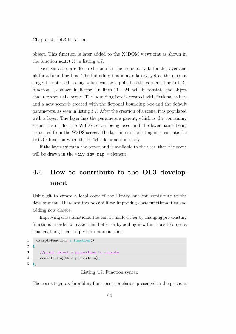
Chapter 4. OL3 in Action
object. This function is later added to the X3DOM viewpoint as shown inthe function addIt() in listing 4.7.
Next variables are declared, cena for the scene, camada for the layer andbb for a bounding box. The bounding box is mandatory, yet at the currentstage it’s not used, so any values can be supplied as the corners. The init()function, as shown in listing 4.6 lines 11 - 24, will instantiate the objectthat represent the scene. The bounding box is created with fictional valuesand a new scene is created with the fictional bounding box and the defaultparameters, as seen in listing 3.7. After the creation of a scene, it is populatedwith a layer. The layer has the parameters parent, which is the containingscene, the url for the W3DS server being used and the layer name beingrequested from the W3DS server. The last line in the listing is to execute theinit() function when the HTML document is ready.
If the layer exists in the server and is available to the user, then the scenewill be drawn in the <div id="map"> element.
4.4 How to contribute to the OL3 develop-ment
Using git to create a local copy of the library, one can contribute to thedevelopment. There are two possibilities; improving class functionalities andadding new classes.
Improving class functionalities can be made either by changing pre-existingfunctions in order to make them better or by adding new functions to objects,thus enabling them to perform more actions.
1 exampleFunction : function()2 {3 //print object’s properties to console4 console.log(this.properties);5 },
Listing 4.8: Function syntax
The correct syntax for adding functions to a class is presented in the previous
64

Chapter 4. OL3 in Action
listing. The function name comes first, followed by : function(), whereadditional parameters can be supplied in between the parenthesis. Inside thebrackets is the code.
Creating a new class to be used by OL3, one uses the following:
1 OL3.Person = new OL3.Class(2 {3 name : "",4 age : 0,5 sex: "",67 initialize : function (name, age, sex)8 {9 this.name = name;
10 this.age = age;11 this.sex = sex;12 },13 getName: function()14 {15 console.log(this.name);16 },17 getAge: function()18 {19 console.log(this.age);20 },21 getSex: function()22 {23 console.log(this.sex);24 },25 greet: function()26 {27 console.log("hello, my name is "+this.name);28 }29 });
Listing 4.9: Class syntax
Any OL3 class uses the OL3.Class template. This template uses the initialize()function as a constructor, and variables are either declared before the construc-tor by name or inside the constructor by name preceded by this.. Functions
65

Chapter 4. OL3 in Action
are created used the example given in listing 4.8. All variables and func-tions declared outside the constructor follow a structure, name : value , orname: function(){} , the comma acts in place of the semicolon, separatingthe various expression that are part of the object.
66

Chapter 5
Conclusions and Future Work
Over the course of the research for the thesis and the library development,a analysis of the current technologies and available libraries for scene navi-gation was made. The new capabilities of HTML5 and WebGL allow for thefirst time a plug in free and browser independent transition from the twodimensional web to a three-dimensional visualization.
Scene navigation libraries can benefit from this three dimension ability,therefore creating a more rich user experience as well as a more detailed dataset. Ol3 intends to be an open source solution that makes use of the newavailable specifications and break free from the two dimensional restraintsexperienced until now. Using JavaScript, X3DOM, X3D and WebGL, thislibrary provides the necessary tools to create a scene and obtain geometryfrom W3DS servers, this being either full models or tiled geometry.
5.1 Research
The research part was a study in the emerging specifications that allow thedevelopment of the library as well as existing open source libraries for scenenavigation. The specifications studied where WebGL, X3D, X3DOM andW3DS.
WebGL, as shown in section 2.1, is an API that allows the use of 3D graph-
67

Chapter 5. Conclusions and Future Work
ics in the browser. Its compatibility with DOM languages such as JavaScript,makes this a powerful tool to create plug in free and browser independent 3Dvisualizations.
X3D, which was discussed in section 2.2, is an open standards file for-mat for the representation of 3D scene graphs, and according to the HTML5specification is the method to declare 3D scenes. Inheriting from VRML andextending its capabilities, this file format extends its predecessor and allowsusers to use the more familiar XML syntax.
Through the use of components and profiles, as seen in subsection 2.2.1,it is possible for content creators to clearly define which features are requiredfrom X3D, therefore creating a more concise experience and visualization indifferent platforms. One setback in X3D is that no method exists to updateor synchronize the X3D elements which allows only a single import of thescene and making it static. This is solved with the use of X3DOM
X3DOM creates a bridge between HTML5 and X3D, overcoming the up-date and synchronization issues between the two. Through this library, it’spossible to create dynamic X3D scenes in the DOM, where users can changeelements and the changes are reflected in the visualization. This scene ma-nipulation is made through DOM scripting languages like JavaScript, leavingthe role of X3D as a scene graph definition and rendering.
W3DS is a service that provides three-dimensional geodata, and alliedwith JavaScript and X3DOM, it is possible to create dynamic scenes whichare loaded from one or several W3DS servers asynchronously and only whenneeded. This allows content creators to develop large amounts of data andstore it in the server, as there is no need to load all the data set. Queryingthe service for details about the data and obtaining the actual data is quitesimple, as the server implements several requests, as shown in section 2.6.These tools are the foundation for the development of the OL3 library.
Besides the study made about the technologies and specifications, a studyabout existing open source libraries for scene navigation was made. The tar-gets of this study were OpenLayers and WebGL Earth.
OpenLayers is an open source JavaScript library which allows the visual-ization of geographical data in browsers. OpenLayers is quite simple to use,
68
Chapter 5. Conclusions and Future Work
and, in an HTML document, one only needs to include the library in thedocument header and create a div element for the map. OpenLayers displaysmap images as tiles, and has a asynchronous loader in order to load the re-quired tiles.
OpenLayers is a quite mature library, with a diverse set of tools and mapsupport, yet it relies on a two-dimensional representation of the world. It isa good reference for tools and asynchronous data loading, but the navigationlacks a dimension.
WebGL Earth is a open source JavaScript library that allows users tocreate and navigate a globe using a browser. Still in the early stages, it im-plements a three-dimensional camera navigation system as well as loadingdata asynchronously, yet the scene only offers a globe with modifiable tex-tures. There is no sense of height and the textures are obtained from WMSservers or can be defined by users. Although a nice step in breaking free fromthe restraints of two dimensional web, the data is still two dimensional andlimited set of tools.
5.2 Implementation
After the research was made and an understanding of the specifications andlibraries required to create OL3 was achieved, the next step was the imple-mentation.
The starting point the was implementation of a name space to avoidcollision with other JavaScript libraries and creating a construct so thereis a similarity with classes as present in Java and C++. After a structurewas defined, the next phase was setting up asynchronous communicationwith the W3DS server, in order to obtain information and data from theWeb Service. The main information provider from the W3DS server is theGetCapabilities, where one can find all information about the W3DS serverand the data contained within. The final requirement was the creation of abounding box class. Bounding boxes are present in WMS servers and W3DSalso uses these objects. Due to their importance in obtaining data and limit-
69

Chapter 5. Conclusions and Future Work
ing geodata extents, OL3 needs this class implemented before heading intoother objects.
The Scene class defines the main OL3 object, which represents a 3D scene.All layers and the camera are a part of the Scene and use it as an access pointto all required data from other objects included in the Scene. This class isalso responsible for accessing the HTML DOM and creating the necessaryelements for the X3DOM view port to be rendered in. The Scene class wasimplemented successfully and handles all required functions.
The Camera was problematic, as there were three different approachesimplemented. The need for constant information about camera position androtation as well as which coordinates delimited the viewing frustum made thisimplementation difficult. The calculation of the viewing frustum used a largeamount of functions and the final result had some issues when swiveling thecamera and had to be abandoned due to the remaining time left for the librarydevelopment was not enough to resolve them. The next approach was the onedescribed in subsection 3.2.2, Emitting Rays, and proven more accurate andwith less lines of code needed. This class is implemented successfully and thebasic functions required are present.
The Layer class is a complex one. Different types of layers in the W3DSserver, tiled and untiled, create a need of versatility in handling requests anddata management. The Layer class went through many versions, and is yetto be completed. In the initial phases, untiled layers where handled just liketiled layers, in order to keep track of loaded geometry, yet at the current state,there is no method to handle scene requests. The scene request method wasdropped as to implement a better tiled layer management, using the cameraproperties and the grid object, as seen in subsection 3.2.3. This new tiledlayer method is nearly finished as there is a grid calculation for needed tilesand there are no requests for already loaded tiles.
One issue left open for the layer object and regarding tile managementis that older tiles which are not needed are still kept in the scene and notdiscarded. Also there is an issue regarding the overlap of tiles. Since oldertiles are not discarded when a new tile of different LOD is required it willoverlap the older tile present. This is an important issue that needs special
70

Chapter 5. Conclusions and Future Work
attention in order to make the Layer class more close to a final version.Other issue left to resolve is handling of the untiled layers, which can be
either as a tiled layer with a fixed size and no LOD or a completely differentapproach using small bounding boxes.
One final requirement for the Layer class is HTML controls for visibilityand implement functions to toggle the Layer visible or invisible. This is yetto be implemented, but a viable solution has been studied.
5.3 Future Work
For future work in OL3, the most important elements in the list is closing theissues the library currently has and were referenced in the previous section.
After completing the pending tasks, one option for future work is incor-porating the Underscore JavaScript library to handle all tasks that requirearray iteration. Since tiled layers can have many arrays and each time thecamera moves there is a need to iterate them in order to manage the tiles,using Underscore can make this task faster.
To make the library more useful another option for future work would bethe creation of another type of Layer. This new object would be designed tohandle buildings and allow a 3D visualization of routing. Just like OpenLay-ers there are implementations of two dimensional indoor routing available,yet these could benefit from a three-dimensional representation as not allnavigation is made in two dimensions.
5.4 Conclusion
The library has the main features implemented, despite the issues reportedin the Layer class. The most difficult task was the Camera implementationdue to the errors encountered, yet the solution found was able to close theissue and required much less functions than the one that had been previously
71

Chapter 5. Conclusions and Future Work
proposed.The library does need more work, in order to be usable by the general
public and to be considered complete and functional, but the developmentmade until now is promising.
72

Bibliography
[1] http://www.webglearth.org/api @ www.webglearth.org. [AccessedSeptember 16th, 2011].
[2] WebGL Specification - Editor’s Draft. https://www.khronos.org/registry/webgl/specs/latest/. [Accessed November 3rd, 2011].
[3] Brutzman, D., and Daly, L. Extensible 3d graphics for web authors.2007.
[4] Caldwell, D. Unlocking the Mysteries of the Bounding Box. ALAMap and Geography Round Table. . . . (2005).
[5] Fernandes, A. R. View Frustum Culling @www.lighthouse3d.com. http://www.lighthouse3d.com/tutorials/view-frustum-culling/. [Accessed May 17th, 2012].
[6] Jung, Y., Behr, J., and Graf, H. X3DOM AS CARRIER OF THEVIRTUAL HERITAGE. Integration The Vlsi Journal (2001), 1–8.
[7] Rocha, J. G., and Oliveira, N. C. W3DS Open Source Implemen-tation. [Accessed May 31st, 2012], 2012.
[8] Samyn, K. Line plane intersection - GNU Octave - a knol by KoenSamyn. [Accessed June 5th, 2012].
[9] Sunday, D. Bounding Containers for Polygons, Polyhedra, and PointSets (2D & 3D).
73

Bibliography
[10] Wesstein, E. W. Line Plane Intersection. http://mathworld.wolfram.com/Line-PlaneIntersection.html. [Accessed June 7th,2012].
74