omae2013-10851
TRANSCRIPT

7/15/2019 OMAE2013-10851
http://slidepdf.com/reader/full/omae2013-10851 1/9
1 Copyright © 2013 by ASME
Proceedings of the ASME 2013 32nd International Conference on Ocean, Offshore and Arctic EngineeringOMAE2013
June 9-14, 2013, Nantes, France
OMAE2013-10851
PIPELINE SHORE APPROACH INSTALLATION BY HORIZONTAL DIRECTIONALDRILLING
Danilo Machado L. da SilvaDETNORSKE VERITAS
Rafael F. SolanoPETROBRAS
Antonio Roberto de MedeirosSUBSEA7
Marcos V. RodriguesDETNORSKE VERITAS
Fabio B. de AzevedoPETROBRAS
ABSTRACTWhenever an export pipeline coming from offshore fields
to onshore facilities is designed, a shore approach solution
needs to be provided, once it can become a very complex
project in terms of offshore pipeline installation. At this phase
the pipeline on-bottom stability is analyzed for surf zone, the
possibility of using concrete coating is verified as well as the
necessary burial depth. In addition, the pipeline installation
stress analysis is performed, the potential for local scour isverified, among other things. In this context, horizontal
directional drilling (HDD) emerges as an alternative method in
which, in addition to overcome the technical aspects mentioned
above, the environmental issues can also be minimized.
Many factors determine the success of an HDD project.
Failure to complete the borehole is often the main concern, as
the project would not be attempted if the pipeline could not be
installed. However, the successful design and construction of an
HDD is measured in more than a successful pullback. The
achievements, as in any project, include the completion of the
project for a reasonable cost with minimal environmental
impact and according to the schedule. And of course, the
pipeline integrity shall be ensured. That is the focus here in thiswork.
This paper presents discussions regarding to the proper
design of the export pipeline section installed by HDD in the
shore approach area. To ensure a proper design and pipeline
integrity are important parts in the success of a shore approach
HDD crossing. It must be noted that there are no methods for in
situ repair of damaged pipelines installed by HDD. The point is
a proper design, construction and installation, which includes,
for instance, do not overstress the pipeline during installation,
mainly pullback operation, as well as the proper selection of the
drill path in order to place the pipeline within stable ground and
isolated from obstacle’s active conditions, to properly consider
the corrosion protection, etc., for the design life of the product
pipe.
INTRODUCTIONThe advantages that HDD could bring to pipeline shore
approaches, compared with the conventional shore pull, open-
cut methods, are now accepted and several pipelines shore
approaches were installed worldwide. The main reasons are that
HDD can mitigate environmental impact and provide greaterburial depths [1].
It should be noted however, that the risks associated with
typical crossings also apply to shore approaches where they are
combined with specific risks related to working in the marine
environment. In fact, shore approaches using horizontal
directional drilling are much more complex and challenging to
complete than typical surface to surface installations. The
increased challenges and complexity arise from an inability to
readily access the exit location, less geotechnical information
associated with seabed sediments, elevation differences between
entry and exit locations, complexity of coordinating diving
operations, tidal and storm influences, bore stability and drilling
fluid management, casing and product pipe installationstrategies, and buoyancy control [2, 3].
The added complexity and challenges that come with
construction of shore approach HDD crossings demand that the
designer and the constructor use appropriate solutions: Planning
and coordination procedures are paramount in the success of
shore approach HDD work, co-ordination of drilling and marine
operations (diving, vessel movements, supply logistics, etc.)
must be carefully undertaken and reviewed.
The HDD design is not the focus of this work,
recommendations and guidelines can be found in [4-8]. The
design considerations that apply to more conventional land
based HDD crossings also apply to shore approach crossings.
7/15/2019 OMAE2013-10851
http://slidepdf.com/reader/full/omae2013-10851 2/9
2 Copyright © 2013 by ASME
However, there are some areas of design that need to be
emphasized when adopting a shore approach crossing.
Geotechnical considerations remain a key component of an
HDD crossing in any environment. Together with geotechnicaland survey work undertaken to assist with design tasks, studies
and data collections relating to tides, currents and sea-states
may be required. These will not only ensure the permanent
works are suitably designed but also provide information that
will allow selection of adequate vessels to be used in crossing
construction, preparation of suitable construction procedures
(anchor plans, handling of pipeline strings etc.) and estimation
of cost and schedule.
Of course, the stresses imposed on the pipeline before,
during and after installation shall be considered and maintained
within allowable limits. Although some general “rules of
thumb” are commonly used to prepare preliminary designs,
more thorough stress analyses are required to verify finaldesign. Initial design parameters based on “rules of thumb” may
include using radius of curvature of at least 1200 times the
pipeline diameter and, for large diameter steel pipe for instance,
sizing the pipeline wall thickness to provide a diameter to
thickness ratio of 50 at most. Many companies specialized in
HDD works have their own programs to analyze the loadings
and stresses imposed on the pipeline and that can be used to
assist in refining and verifying designs [9].
Corrosion protection is also part of the design
considerations. In many cases, the pipeline coating system is
defined to provide not only adequate corrosion protection but
also to incorporate additional abrasion resistance to keep the
anticorrosive coating system during the pipeline installation intothe HDD crossing.
It should be highlighted that there are no methods for in
situ repair of damaged pipelines installed by HDD. Therefore, it
is necessary to ensure the quality of pipeline design,
construction and installation.
The objective of this work is to present relevant issues
related to the proper design of the export pipeline section
installed by HDD in the shore approach crossing.
HDD DESIGNThe preliminary characteristics of crossings are related to
crossing location and nature of the obstacle, as well as the
pipeline to be installed.
Obstacle to Be Crossed
The geotechnical conditions have an important effect on
works. Geotechnical conditions affect the feasibility of using
HDD as the method of construction, the selection of the
crossing’s trajectory, the pipeline design, the HDD construction
techniques (including the choice of tooling), and the rate of
progress for the construction. Hence, the geotechnical
conditions not only dictate the suitability of HDD as the chosen
method, but also they have a large influence on the construction
cost.
Therefore, the first step in designing a HDD drill path
consists of defining the obstacle to be crossed: the natural or
manmade feature to be negotiated shall be characterized in
terms of its existent physical dimensions as well as thepossibility for such parameters to change with the passage of
time. Adjacent property and use restrictions, as well as future
developments in the area must also be assessed.
Pipeline to Be Installed
The primary criterion governing the specification of pipe to
be installed by HDD is its service and the fluid to be
transported: the wall thickness and specified minimum yield
strength will be determined by applicable codes and regulations.
However, stresses and loads imposed by the installation method
shall be reviewed and analyzed in combination with operating
stresses to assure that acceptable limits are not exceeded.
In addition to site features, i.e., geotechnical andtopographical conditions, the geometry of the bore hole must be
matched to the pipe being installed, as during HDD installation
the pipeline is subjected to tension required to pull the pipe into
the bore hole and around curved sections. The tension comes
from the drag due to the friction between pipe and bore hole
and the fluid drag caused by pulling the pipe through the
viscous drilling mud trapped in the annulus. In addition, tension
results from the unbalanced gravity effects of pulling the pipe
into and out of the bore hole at different elevations. The
bending loads are caused as the pipe is forced through the
curves in the bore hole, and the external loads result from the
pressure exerted by the drilling mud in the annulus around the
pipe. Prior to the installation of a horizontal directional drilledpipe it is important to estimate the pipe pullback force during
installation so that:
(1) the pipe is not overstresses during HDD installation;
(2) a drill rig with sufficient pullback capacity is used;
(3) an economical design is implemented.
There are several approaches for calculation of pullback
forces during the pipeline installation by HDD [10-12], one of
the most used method was proposed by the PRCI [8].
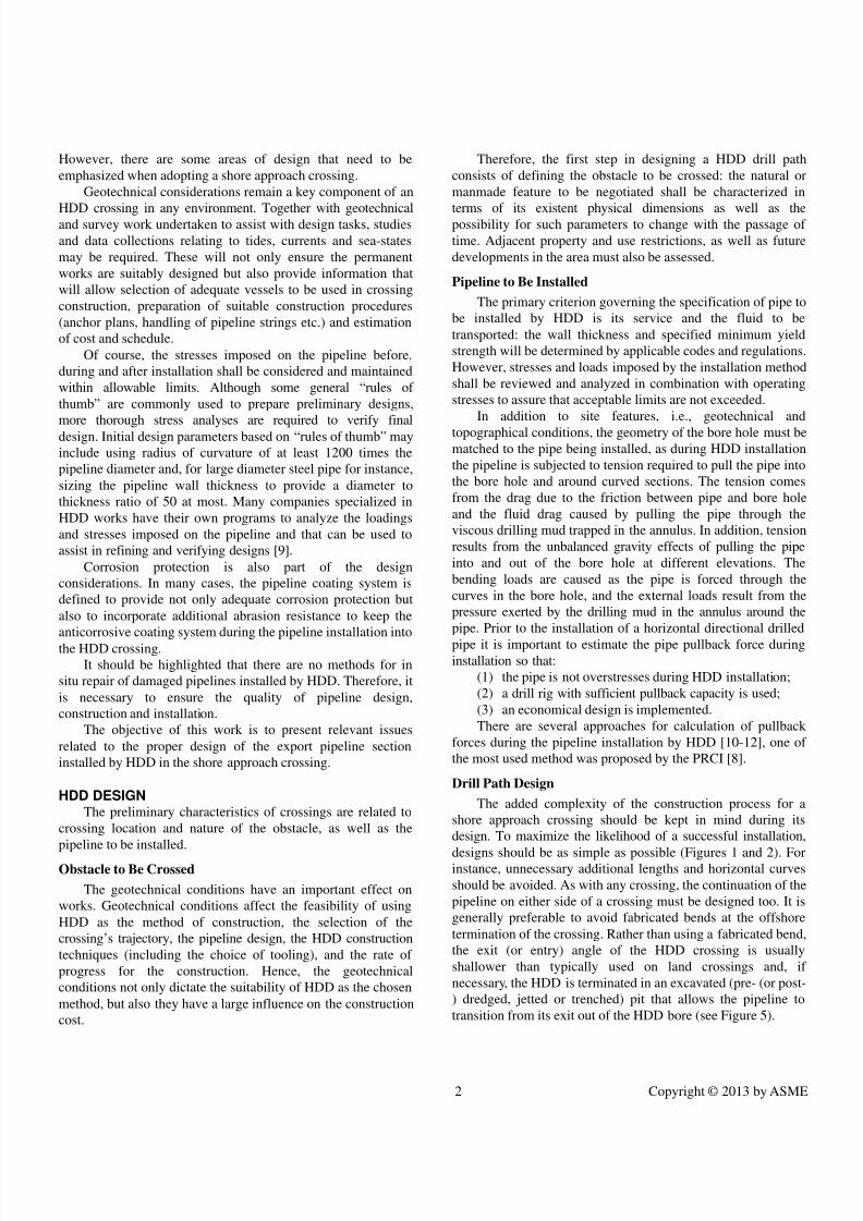
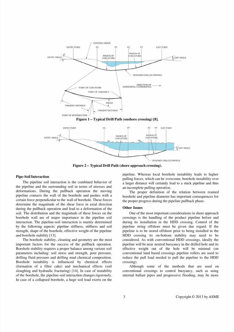
Drill Path Design
The added complexity of the construction process for a
shore approach crossing should be kept in mind during its
design. To maximize the likelihood of a successful installation,
designs should be as simple as possible (Figures 1 and 2). For
instance, unnecessary additional lengths and horizontal curves
should be avoided. As with any crossing, the continuation of the
pipeline on either side of a crossing must be designed too. It is
generally preferable to avoid fabricated bends at the offshore
termination of the crossing. Rather than using a fabricated bend,
the exit (or entry) angle of the HDD crossing is usually
shallower than typically used on land crossings and, if
necessary, the HDD is terminated in an excavated (pre- (or post-
) dredged, jetted or trenched) pit that allows the pipeline to
transition from its exit out of the HDD bore (see Figure 5).
7/15/2019 OMAE2013-10851
http://slidepdf.com/reader/full/omae2013-10851 3/9
3 Copyright © 2013 by ASME
Figure 1 – Typical Drill Path (onshore crossing) [8].
Figure 2 – Typical Drill Path (shore approach crossing).
Pipe-Soil Interaction
The pipeline soil interaction is the combined behavior of
the pipeline and the surrounding soil in terms of stresses and
deformations. During the pullback operation the moving
pipeline contacts the wall of the borehole and pushes with a
certain force perpendicular to the wall of borehole. These forces
determine the magnitude of the shear force in axial direction
during the pullback operation and lead to a deformation of the
soil. The distribution and the magnitude of these forces on the
borehole wall are of major importance in the pipeline soil
interaction. The pipeline-soil interaction is mainly determined
by the following aspects: pipeline stiffness, stiffness and soil
strength, shape of the borehole, effective weight of the pipelineand borehole stability [13].
The borehole stability, cleaning and geometry are the most
important factors for the success of the pullback operation.
Borehole stability requires a proper balance among various soil
parameters including: soil stress and strength, pore pressure,
drilling fluid pressure and drilling mud chemical composition.
Borehole instability is influenced by chemical effects
(formation of a filter cake) and mechanical effects (soil
sloughing and hydraulic fracturing) [14]. In case of instability
of the borehole, the pipeline-soil interaction changes rigorously.
In case of a collapsed borehole, a huge soil load exerts on the
pipeline. Whereas local borehole instability leads to higher
pulling forces, which can be overcome, borehole instability over
a larger distance will certainly lead to a stuck pipeline and thus
an incomplete pulling operation.
The proper definition of the relation between reamed
borehole and pipeline diameter has important consequences for
the proper progress during the pipeline pullback phase.
Other Issues
One of the most important considerations in shore approach
crossings is the handling of the product pipeline before and
during its installation in the HDD crossing. Control of the
pipeline string offshore must be given due regard. If the
pipeline is to be stored offshore prior to being installed in theHDD crossing its on-bottom stability may need to be
considered. As with conventional HDD crossings, ideally the
pipeline will be near neutral buoyancy in the drilled hole and its
effective weight out of the hole will be minimal (on
conventional land based crossings pipeline rollers are used to
reduce the pull load needed to pull the pipeline to the HDD
crossing).
Although some of the methods that are used on
conventional crossings to control buoyancy, such as using
internal ballast pipes and progressive flooding, may be more
7/15/2019 OMAE2013-10851
http://slidepdf.com/reader/full/omae2013-10851 4/9
4 Copyright © 2013 by ASME
difficult to implement offshore, there are several methods that
can be used to provide suitably weighted pipeline strings.
In some cases, it can be technically feasible to increase the
pipeline’s wall thickness to provided added weight that, whenthe pipeline is empty, will give near ideal effective weight
downhole and reasonable stability on the seabed. Although that
added wall thickness may not be necessary with respect to
pipeline stresses, it may be an effective, and economical,
method of aiding and enabling installation by increasing the
submerged weight of the pipeline.
Similarly, although less common and not recommended, the
use of concrete coating on pipe that is to be installed into HDD
bores is a method of increasing the effective weight of an
otherwise buoyant pipeline. If a concrete weight coat is used to
this objective it is important to ensure that it is a high quality
application that will not spall during handling and installation. A
concrete weight coat will obviously increase the outsidediameter of the pipeline being installed. In order to minimize
the coating’s thickness, and hence minimize the size of the
reamed HDD bore, a dense concrete should be used.
PIPELINE DESIGNThe design and installation of pipelines must comply with
established standards, ensuring safety and specifying the
minimum requirements to be satisfied by the designer.
DNV-OS-F101 [15] considers a design practice based on
so-called limit states for the pipeline design. In the limit state
design, all relevant failure modes for a pipe are formulated as
limit states, which are classified into one of the four categories:
1. Serviceability Limit State (SLS),2. Ultimate Limit State (ULS),
3. Fatigue Limit State (FLS),
4. Accidental Limit State (ALS).
The limit state is the limit between an acceptable and
unacceptable condition expressed in mathematical terms
derived through design formulas for a given failure mode. The
limit state design identifies the different failure modes and
provides specific design checks to ensure structural integrity.
The pipeline capacity is then characterized by the actual
capacity of each individual failure mode.
The structural analysis of an offshore pipeline regarding
construction and installation phases deals with the computation
of deformations, internal forces, and stresses as a result of external loads and the structural properties of the pipe.
Structural deformation of the pipe during construction
depends on the method and equipment used for installation, the
structural properties of the pipe and the environmental loads.
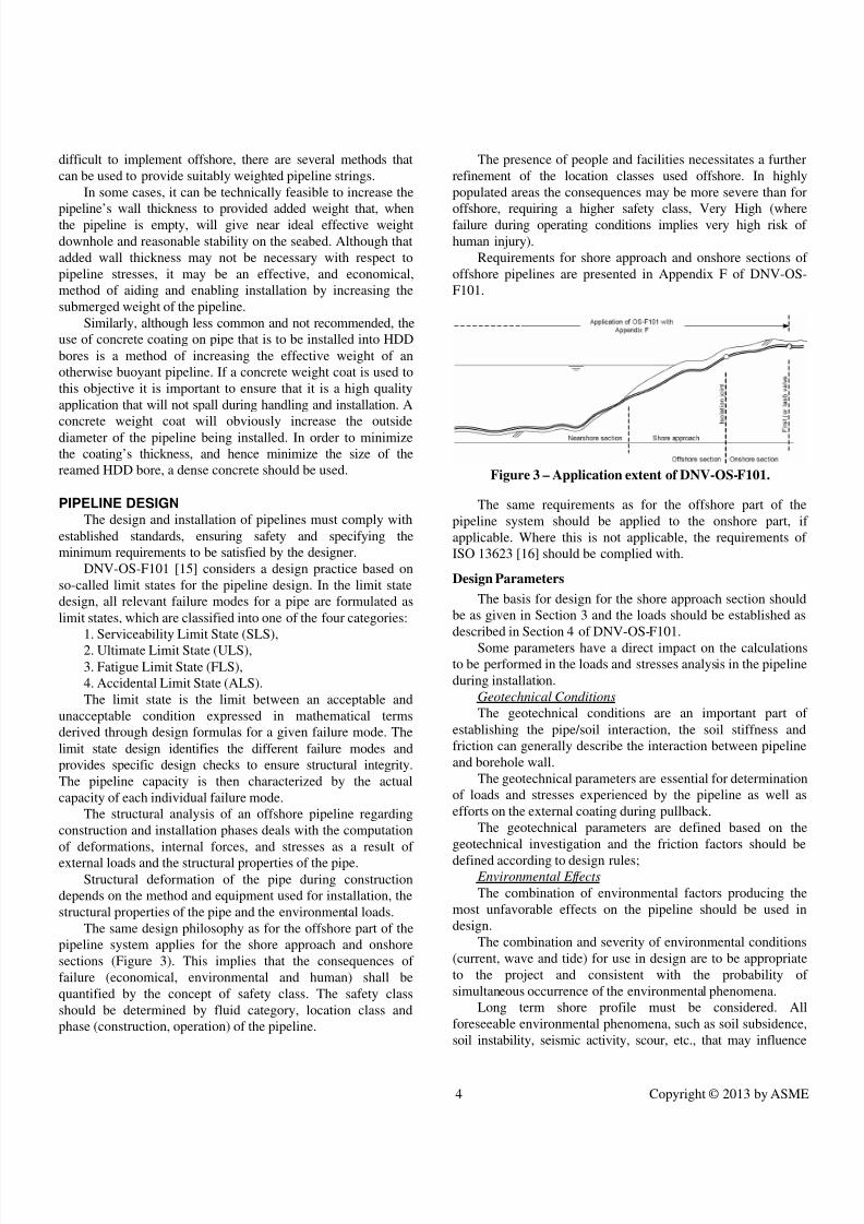
The same design philosophy as for the offshore part of the
pipeline system applies for the shore approach and onshore
sections (Figure 3). This implies that the consequences of
failure (economical, environmental and human) shall be
quantified by the concept of safety class. The safety class
should be determined by fluid category, location class and
phase (construction, operation) of the pipeline.
The presence of people and facilities necessitates a further
refinement of the location classes used offshore. In highly
populated areas the consequences may be more severe than for
offshore, requiring a higher safety class, Very High (wherefailure during operating conditions implies very high risk of
human injury).
Requirements for shore approach and onshore sections of
offshore pipelines are presented in Appendix F of DNV-OS-
F101.
Figure 3 – Application extent of DNV-OS-F101.
The same requirements as for the offshore part of the
pipeline system should be applied to the onshore part, if
applicable. Where this is not applicable, the requirements of
ISO 13623 [16] should be complied with.
Design Parameters
The basis for design for the shore approach section should
be as given in Section 3 and the loads should be established as
described in Section 4 of DNV-OS-F101.Some parameters have a direct impact on the calculations
to be performed in the loads and stresses analysis in the pipeline
during installation.
Geotechnical Conditions
The geotechnical conditions are an important part of
establishing the pipe/soil interaction, the soil stiffness and
friction can generally describe the interaction between pipeline
and borehole wall.
The geotechnical parameters are essential for determination
of loads and stresses experienced by the pipeline as well as
efforts on the external coating during pullback.
The geotechnical parameters are defined based on the
geotechnical investigation and the friction factors should bedefined according to design rules;
Environmental Effects
The combination of environmental factors producing the
most unfavorable effects on the pipeline should be used in
design.
The combination and severity of environmental conditions
(current, wave and tide) for use in design are to be appropriate
to the project and consistent with the probability of
simultaneous occurrence of the environmental phenomena.
Long term shore profile must be considered. All
foreseeable environmental phenomena, such as soil subsidence,
soil instability, seismic activity, scour, etc., that may influence
7/15/2019 OMAE2013-10851
http://slidepdf.com/reader/full/omae2013-10851 5/9
5 Copyright © 2013 by ASME
the pipeline integrity must be described in terms of their
characteristic parameters relevant to operational and strength
evaluations.
Definition of Design Loads
It must be verified that the pipeline, as designed, is capable
of withstanding all loads that may be reasonably anticipated for
the installation by HDD as well as testing and operation.
The following loads should be considered:
Installation Loads: tension/compression, bending and
external pressure;
Operating Loads: internal pressure, bending, thermal
expansion, external pressure.
The analysis should consider the load combination that
yields the most unfavorable conditions in terms of overall stress
utilization.
Stresses associated with each load as well as the combinedstresses shall be evaluated in accordance with the allowable
limits.
Installation Stress: tensile and compressive stresses,
bending stress, external hoop stress, combined installation
stresses.
Operating Stresses: internal hoop stress, bending stress,
thermal stress, combined stresses.
The methods used in definition of the design loads should
be selected in accordance with good engineering practice.
Methods of analysis may be based on analytical, numerical or
empirical models, or a combination of these methods.
The definition of the design loads for the HDD pipeline
design verification should be performed considering the radiusof curvature for the designed drill path and reassessed, prior
pullback operation, using the actual (as built) drilled path.
Design Criteria
Design and acceptance criteria for the possible modes of
failure are presented in Section 5 of DNV-OS-F101, together
with complementary requirements given in Appendix F.
All relevant failure modes must be considered in design for
all relevant phases and conditions listed in Section 4 of DNV-
OS-F101.
CORROSION PROTECTIONPipeline coating and cathodic protection will not directly
influence the feasibility of a crossing. However, an operational
risk that should be addressed is external corrosion due to
damaged pipeline coatings. Protective coatings are susceptible
to damaging during pullback operation by the forces involved,
and by contact with soils, rocks, and other debris in the bore
hole. The consequences of coating damage are intensified by
the nature of the HDD method. A pipeline installed by HDD
will not be readily accessible to future pipeline or coating
repairs.
The mitigation of such effects is related to good design and
execution of borehole as well as correct specification and use of
the external coating.
External Coating
External coating refers to factory applied external coating
systems with a corrosion protection function. Coating systems
may further include an outer layer for mechanical protection.Coatings used for HDD drag sections shall be flexible and
have sufficient abrasion resistance to limit damage during
installation.
External coatings should possess suitable mechanical and
electrical properties in relation to the pipe size, environment
and operating conditions. External coatings should be factory-
applied, except for field joints and other special regions or
components, which may be coated on site.
Parameters that should be taken into account when
evaluating the effectiveness of external coatings include:
• Design/service conditions;
• Resistance to abrasion;
• Electrical resistivity of the coating;• Required adhesion between the coating and the
pipeline base material;
• Required resistance to shear forces;
• Susceptibility to cathodic disbondment;
• Resistance to ageing, brittleness and cracking;
• Resistance to chemical attack;
• Resistance to damage during handling, shipping,
storage, installation and service.
Consideration should be given to the use of coatings with
enhanced abrasion-resistant properties or with additional
abrasion resistant outer layers on sections where coated pipe is
to be installed by HDD [17].
Field Joint Coating
Field joint coating (FJC) refers to single or multiple layers
of coating applied to protect girth welds and the associated cut-
back of the linepipe coating, irrespective of whether such
coating is actually applied in the field or in a factory.
The welded joints must be coated using a system
compatible with the factory coating provided on the rest of the
pipe.
The FJC shall be designed to have its integrity guaranteed
during and after the pullback operation. If necessary,
qualification tests should be performed.
The preparation of the pipe surface and the application of
the field joint coating must be performed in accordance with a
procedure that meets the coating manufacturer’s
recommendations.
The design and quality control during manufacture of field
joint coatings is essential to the integrity of pipelines.
As for external coatings, integrity of field joint coatings
must be ensured during the pullback operation.
Cathodic Protection
External coating system defects enable the pipeline steel to
come into contact with the electrolyte in its surroundings,

7/15/2019 OMAE2013-10851
http://slidepdf.com/reader/full/omae2013-10851 6/9
6 Copyright © 2013 by ASME
resulting in pipeline corrosion. Cathodic protection system must
be designed and installed to mitigate this corrosion.
The design of cathodic protection system should be in
accordance with ISO 15589-2 [18] or DNV-RP-F103 [19].Even though, these rules do not have specific requirements for
the HDD section.
Cathodic protection may be applied by the sacrificial anode
or impressed current method. A combination of both systems
could also be considered, but the need for insulation between
both systems should be evaluated.
The current density must be appropriate to the pipeline
temperature, the selected coating type and to the environment to
which the pipeline is exposed, considering coating degradation
and coating damage during pullback.
In all cases, points for testing should be defined as close to
the HDD ends as possible;
Simulations through cathodic protection modeling shouldbe performed to evaluate the effectiveness of the cathodic
protection design along the HDD length.
The formation characteristics (electrical resistivity) along
borehole and coating breakdown factor (related to the HDD
section) should be taken into account for the project design life.
The galvanic anodes should be installed on the submerged
side, preferably in sled structures with a reliable electrical
connection to the pipeline. The installation of anodes directly
on the pipeline is also an alternative. In both cases, it shall be
considered the effects of anodes located too close to each other,
i.e., less than 0.5 meters from each other.
The impressed current system, installed on the onshore side
of the pipeline, can be used for cathodic protection of the HDDsection if the cathodic protection potential measured at the entry
point is deficient. However, the consequences over the
sacrificial anodes at the offshore side should be evaluated.
OTHER CONSIDERATIONSOther considerations are presented as follows. In general,
the same requirements as for the offshore part of the pipeline
system should be applied to the shore approach part, whenever
applicable.
Pipeline Installation
The pipeline laying of the HDD section shall be performed
according to the same requirements applied to the offshore partof the pipeline.
For marine crossings where the pipeline construction will
be continued away from the crossing after the HDD installation
has been completed, it is usual that the pipeline segment that is
pulled into the HDD crossing will have a “tail” length of
pipeline attached. Generally, such a tail will be left on the
seabed at the conclusion of the HDD pullback and be of such alength that, at a later date, a laybarge will be able to bring the
pipe into its welding stalls and conventionally lay-away. The
length of these tail sections is usually determined based on the
depth of water and the vessel(s) being considered (Figure 4).
The designer must be mindful that the tail section will add to
the forces required during pullback. Buoyancy comes into play
again with the tail section since, in order to provide a tail that is
stable, or easily controlled, and that does not prohibitively add
weight to pullback string, the effective weight of the pipe when
submerged must be considered. The tail section may have
different stability issues compared with those associated with
the pipe being installed in the HDD bore. Since the tail section
is not being installed in the HDD bore it will not only requirecontrol prior to and during the pullback operation but it will
also need to be stable and secure during operational conditions
(via, for instance, pre-trenching, post-burial, and protection
measures) [9].
To ensure that the exit point (product pipe entry point) will
not be affected by the pipeline recovery and tie-in operations, a
proper pipeline length to remain outside borehole shall be
considered, in addition to the catenary length required for lifting
and tie-in operations. This pipeline length shall guarantee that
vessel movements will not be transferred to the exit point.
Product pipe position before pullback
It is recommended to place the pipeline section to be
installed into borehole as close to the exit point as possible,considering the laying corridor and installation route;
The minimum distance from the pull head to exit point
must allow all necessary corrections due to misalignment
between product pipe and drill path. Therefore, this procedure
ensures that the product pipe will have the correct alignment at
exit point during pullback.
The pipeline section to be pulled through the borehole must
be positioned as aligned as possible with the drill path
(alignment with the drill path exit point).
If such alignment is not possible, the mechanical loads to
be experienced by the product pipe (tension, friction and
possible damage to external coating, increase in pulling force,
etc.) should be considered. Furthermore, aspects related to theintegrity of borehole exit point should also be considered
(widening, collapse of borehole exit point).
Figure 4 – Total Pipeline Length of HDD Section.
7/15/2019 OMAE2013-10851
http://slidepdf.com/reader/full/omae2013-10851 7/9
7 Copyright © 2013 by ASME
Pipeline Hydrotest
Gauging and hydrostatic test should be performed prior and
after pullback operation.Hydrostatic test procedures should be in accordance with
requirement in DNV-OS-F101, but, a reduced hold period could
be accepted provided that the HDD section will be pre-
commissioned after connection the to the remain sections of the
pipeline system.
On-Bottom Stability Considerations
The pipeline (HDD section) must be designed to be stable
during installation, hydrotest and operation, in accordance with
the applied design standards.
On-bottom stability may be an issue for the length of the
HDD pipeline section that remains outside borehole after
pullback.
Pipeline on-bottom stability analysis must be performed in
order to evaluate if the pipeline may experience movements that
could adversely affect its integrity.
Note that actions should be taken to ensure that the pipeline
will be prevented from movements before pullback. Such
actions include flooding and/or anchor the pipeline prior
pullback.
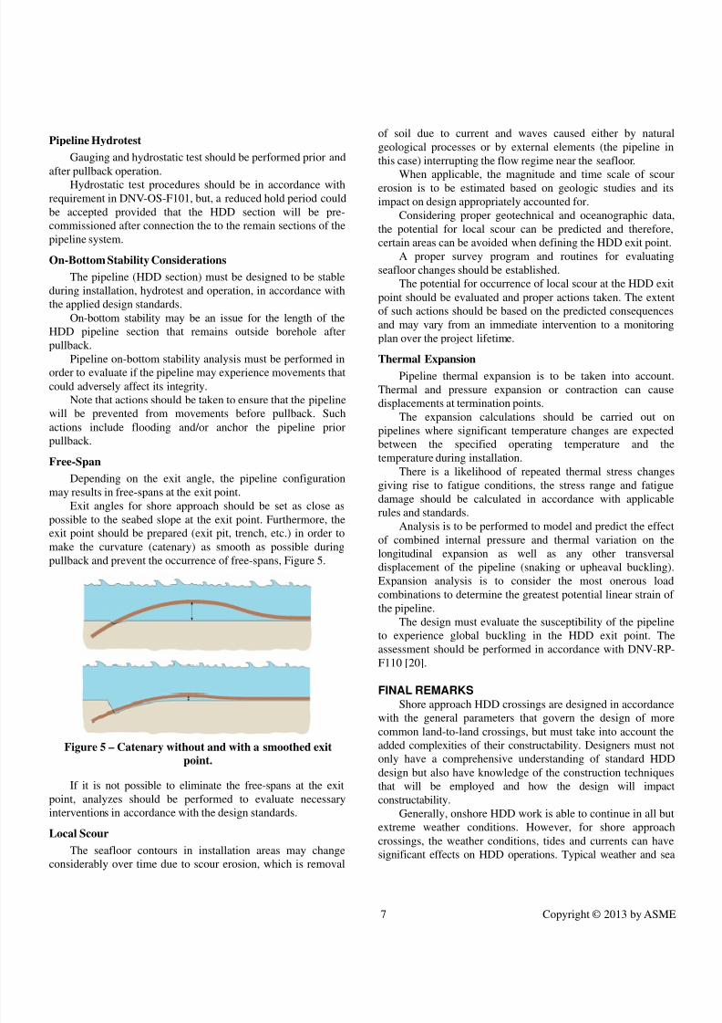
Free-Span
Depending on the exit angle, the pipeline configuration
may results in free-spans at the exit point.
Exit angles for shore approach should be set as close as
possible to the seabed slope at the exit point. Furthermore, the
exit point should be prepared (exit pit, trench, etc.) in order tomake the curvature (catenary) as smooth as possible during
pullback and prevent the occurrence of free-spans, Figure 5.
Figure 5 – Catenary without and with a smoothed exit
point.
If it is not possible to eliminate the free-spans at the exit
point, analyzes should be performed to evaluate necessary
interventions in accordance with the design standards.
Local Scour
The seafloor contours in installation areas may change
considerably over time due to scour erosion, which is removal
of soil due to current and waves caused either by natural
geological processes or by external elements (the pipeline in
this case) interrupting the flow regime near the seafloor.
When applicable, the magnitude and time scale of scourerosion is to be estimated based on geologic studies and its
impact on design appropriately accounted for.
Considering proper geotechnical and oceanographic data,
the potential for local scour can be predicted and therefore,
certain areas can be avoided when defining the HDD exit point.
A proper survey program and routines for evaluating
seafloor changes should be established.
The potential for occurrence of local scour at the HDD exit
point should be evaluated and proper actions taken. The extent
of such actions should be based on the predicted consequences
and may vary from an immediate intervention to a monitoring
plan over the project lifetime.
Thermal Expansion
Pipeline thermal expansion is to be taken into account.
Thermal and pressure expansion or contraction can cause
displacements at termination points.
The expansion calculations should be carried out on
pipelines where significant temperature changes are expected
between the specified operating temperature and the
temperature during installation.
There is a likelihood of repeated thermal stress changes
giving rise to fatigue conditions, the stress range and fatigue
damage should be calculated in accordance with applicable
rules and standards.
Analysis is to be performed to model and predict the effectof combined internal pressure and thermal variation on the
longitudinal expansion as well as any other transversal
displacement of the pipeline (snaking or upheaval buckling).
Expansion analysis is to consider the most onerous load
combinations to determine the greatest potential linear strain of
the pipeline.
The design must evaluate the susceptibility of the pipeline
to experience global buckling in the HDD exit point. The
assessment should be performed in accordance with DNV-RP-
F110 [20].
FINAL REMARKS
Shore approach HDD crossings are designed in accordancewith the general parameters that govern the design of more
common land-to-land crossings, but must take into account the
added complexities of their constructability. Designers must not
only have a comprehensive understanding of standard HDD
design but also have knowledge of the construction techniques
that will be employed and how the design will impact
constructability.
Generally, onshore HDD work is able to continue in all but
extreme weather conditions. However, for shore approach
crossings, the weather conditions, tides and currents can have
significant effects on HDD operations. Typical weather and sea
7/15/2019 OMAE2013-10851
http://slidepdf.com/reader/full/omae2013-10851 8/9
8 Copyright © 2013 by ASME
conditions can affect the selection of equipment and methods of
construction.
Two crucial points in the HDD crossing design consist of
defining the obstacle to be crossed and the pipeline to beinstalled.
It should be noted that, in general, drilling companies’ main
concern is to keep the borehole integrity and control loads and
stresses on drilling equipment. On the order hand, the
determination of loads and efforts to be experienced by the
product pipe as result of the HDD is a primary concern for
owners and pipeline designers.
The proper design and integrity assurance of the installed
pipeline is an important part in the success of a HDD crossing.
Taking into account the pipeline issues is essential for the
success of the project. It is necessary to keep in mind that not
only a finished product is important, but a finished product that
is in good working condition, considering its design life. Thismeans that the pipeline shall withstand the expected operational
conditions and design loads, maintain its integrity, and have a
proper corrosion protection system. The best way to achieve
this is to make sure that the prefabricated pipeline fulfills these
requirements before starting the pulling operation.
The pipeline design must verify adequate strength during
all installation phases in the HDD process. All loads that the
pipeline will experience over the project lifetime should be
considered, which includes installation (construction, pipelay
and pullback), tests and operation.
NOMENCLATURE
ALS: Accidental Limit StateDNV: Det Norske Veritas
FJC: Field Joint Coating
FLS: Fatigue Limit State
HDD: Horizontal Directional Drilling
ISO: International Organization for Standardization
PRCI: Pipeline Research Council International
SLS: Serviceability Limit State
ULS: Ultimate Limit State
ACKNOWLEDGMENTSThe authors would like to express their special gratitude to
company managements for allowing this paper to be published.
REFERENCES[1] Medeiros, A. R., Silva, D. M. L., Solano, R. F., Siqueira,
J., “HDD as an Alternative Solution for Shore Approach
of Offshore Pipelines in Brazilian Scenarios”, Rio Pipeline
Conference & Exposition 2011, Rio de Janeiro, Brazil,
2011.
[2] Duyvestyn, G., “Design and Construction Challenges for
HDD Shore Crossings”. Proc. of No-Dig Conference,
North American Society for Trenchless Technology –
NASTT, Orlando, Florida, USA, 2005.
[3] Smith, N., “Horizontal Directional Drilling (HDD) for
Shore Approach Applications”. Rio Pipeline Conference
& Exposition 2003, Rio de Janeiro, Brazil, 2003.
[4] CAPP, “Planning Horizontal Directional Drilling forPipeline Construction”, Canadian Association of
Petroleum Producers, 2004.
[5] DCA, “Information and Recommendations for the
Planning, Construction and Documentation of HDD
Projects”, Drilling Contractors Association (DCA-
Europe), 3rd
edition, 2009.
[6] DCCA, “Guidelines for a Successful Directional Crossing
Bid Package”, Directional Crossing Contractors
Association, 1995.
[7] HDD Consortium, “Horizontal Directional Drilling Good
Practices Guidelines”, 3rd
edition, 2008.
[8] PRCI, “Installation of Pipeline by Horizontal Directional
Drilling - An Engineering Design Guide”, Pipeline Research Council International, Catalog No. L52290,
2008.
[9] Smith, N., "Aspects of Design and Construction Relating
to Marine HDD Installations", 3rd
International Indonesia
Pipeline Conference & Exhibition, Jakarta - Indonesia,
2010.
[10] Huey, D. P., Hair, J. D., Mcleod, K. B., “Installation
loading and stress analysis involved with pipeline installed
by horizontal directional drilling”. Proc. of No-Dig
Conference, New Orleans, LA, 1996.
[11] Puckett, J. S., “Analysis of Theoretical Versus Actual
HDD Pulling Loads”, ASCE "Pipelines 2003" Conference,
Baltimore, Maryland, 2003.[12] Cheng, E., Polak, M. A., “Theoretical Model for
Calculating Pulling Loads for Pipes in Horizontal
Directional Drilling”, Tunnelling and Underground Space
technology, n.22, p. 633-643, 2007.
[13] Kruse, H. M. G., Brink, H. J, “Risks During the Pull Back
Operation of Horizontal Directional Drilling”,
Mediterranean NO DIG 2007 – XXV th
International
Conference & Exhibition, Roma, 2007.
[14] Wang, X., Sterling, R. L., “Stability Analysis of a
Borehole wall During Horizontal Directional Drilling”,
Tunnelling and Underground Space technology, n.22, p.
620-632, 2007.
[15] DNV-OS-F101, “Submarine Pipeline Systems”, Det Norske Veritas, August 2012.
[16] ISO 13623, "Petroleum and natural gas industries —
Pipeline transportation systems", 2nd
edition, International
Organization for Standardization, 2009.
[17] PRCI, "Coating Requirements for Pipelines Installed By
Horizontal Directional Drilling and Slip Boring", Pipeline
Research Council International, 2000.
[18] ISO 15589-2:2004(E), “Petroleum and natural gas
industries - Cathodic protection of pipeline transportation
systems — Part 2: Offshore pipelines”, 1st
edition,
International Organization for Standardization, 2004.

7/15/2019 OMAE2013-10851
http://slidepdf.com/reader/full/omae2013-10851 9/9
9 Copyright © 2013 by ASME
[19] DNV-RP-F103, “Cathodic Protection of Submarine
Pipelines by Galvanic Anodes”, Det Norske Veritas,
October 2010.
[20] DNV-RP-F110, “Global Buckling of Submarine Pipelines- Structural Design due to High Temperature/High
Pressure, Det Norske Veritas, October 2007.