on the motion characteristics and effects of dome for usv
TRANSCRIPT

On the motion characteristics and effects of dome for USV in actual seas
Junya Dobashi1 and Hajime Kihara2
ABSTRACT The accurate prediction of ship motions is indispensable for the successful operation of the USV, which communicates with the UUV in underwater using acoustic sensors, because the directivity angle for acoustic communication with the UUV depends on the rolling angle. The influence of the USV's hull form on ship motions in actual seas is discussed in the present study.
KEY WORDS USV; UUV; Cooperative operation; Directivity angle; Acoustic communication; Large amplitude motion; Dome shape. INTRODUCTION
Using the underwater communication with acoustic sensors, the USV (Unmanned Surface Vehicles) receives the information for the missions from the UUV (Unmanned Underwater Vehicles), and sends the positional information obtained from GPS to the UUV for the purpose of having accurate self-location. For accomplishing these cooperative operations, the hull of the USV needs for the extra space to store some instruments including acoustic sensors and so on. So the hull form with a dome for the instruments is distinctive in shape. Additionally the draft of the USV is shallow in general and it is about 0.3 meter in the case of the USV dealt with in the present study (Kaba 2015). The incident waves are relatively large to the USV and its ship motions become large even if the Sea State number is low. It is crucial for the successful operation of the USV to predict the motion characteristics in actual seas because the directivity angle for acoustic communication with the UUV depends on the rolling angle (Dobashi 2014). The linear theory for the wave-making of a ship is valid for the prediction of ship motions, and often used for ship design. However, the nonlinear effects in the motion response to waves must be taken into account for the accurate prediction of ship motions (Yamamoto et al. 1978).
The study targets to investigate the influence of the dome shape attached to the hull bottom for the motion characteristics of the USV. Such an appendage considerably affects ship resistance and ship motions. So it is important to determine the principal dimensions and geometrical shape of the appendage from a hydrodynamic viewpoint for the propulsion and sea-keeping performance. For the primary design of the USV, the computational program for the nonlinear ship motions in time-domain is newly developed in the present study. The strip method is employed for the hydrodynamic force and moment acting the hull, but nonlinear effects for not only restoring and Froude-Krylov forces but also radiation and diffraction forces are taken into account in practical manners. This approach is adopted from a viewpoint of cost effectiveness in the hull form design. First the validation tests of the present nonlinear method are studied with the free running test and the computational results based on the linear approach. Secondly the nonlinear effects of wave height are studied to both longitudinal and lateral motions, which cannot be analyzed in the linear theory. Finally the influence of the dome shape at the hull bottom on ship motions is studied to obtain the knowledge in the USV design. The significant values of the rolling in irregular waves are evaluated with the developed computational method. HULL FORM OF USV
The acoustic communication system by which the USV on the free surface runs parallel to the UUV running under water is illustrated in Figure 1. The USV receives the data about a submerged object from the UUV, for example, it’s like in minesweeping, and sends the data obtained from GPS to the UUV for the purpose of having accurate self-location. The body
1 Technical Research and Development Institute, Ministry of Defense of Japan 2 National Defense Academy of Japan
- 237 -
12th International Marine Design Conference 2015 Proceedings Volume 2

Figure 1: Acoustic communication system
Figure 2: Body plan of the USV’s hull form
Table 1: Principal dimensions
Length of water line 6.11 m Breadth 2.38 m Designed draft 0.90 m Depth 1.05 m Displacement 3.78 ton Water plane area 12.32 m2 Position of longitudinal center of buoyancy 0.79 m Height of center of gravity from keel 0.14 m Metacentric height 1.56 m Longitudinal Metacentric height 8.22 m
-plan of the USV used in the present study is shown in Figure 2, and its principal dimensions in Table 1. The USV is designed with Sea State 2 in mind, and maximum and cruse speed is 7 knot and 5 knot, respectively (Dobashi 2014).
The USV has a dome-shaped storage at the hull bottom, in which two devices for acoustic communication are arranged, one is a device to receive the data including graphics about the object obtained by the UUV, and the other is one to send the GPS data to the UUV to control self-location. The cross section of the dome and its view are shown in Figure 3. The wing section is NACA0015 and 2.8 meter long. The distance between two communication devices is 2.0 meter to avoid acoustic
- 238 -
12th International Marine Design Conference 2015 Proceedings Volume 2

Figure 3: Cross section and view of the dome attached to USV interference. The dome is attached to the main hull with the distance between centers of the main hull and the dome 0.88 meter away. THEORETICAL CALCULATIONS
With the computational program newly developed in the present study, the ship motions in waves are calculated in time domain by the time evolution of motion equations. The hydrodynamic force and moment acting the hull are calculated using the strip method, in which the two dimensional boundary value problems for the cross sections corresponding to instantaneous wetted surface are solved over all the ship. The nonlinear effects due to the fact that the incoming waves and induced motions are considered not infinitesimal but finite, are taken into account practically in the computation for not only restoring and Froude-Krylov forces but also radiation and diffraction forces. When boundary value problems are described in the inertial coordinate system, the shape of hull surface to be treated in the strip method, changes with time due to pitching. The assumption that the cross section can be represented with that in the mean position for an oscillatory ship, as it is adopted in linear strip method, causes estimation errors for hydrodynamic forces in large motions, particularly in bow and stern part (Kunugi et al. 2012). In the present method such effects are taken into account by employing the coordinate transformation, although they are neglect in an ordinary nonlinear strip approach.
Radiation and Diffraction Force
The strip method is used for the hydrodynamic force and moment, and it differs from the linear strip method only in that the wetted hull surface changing in response to ship motion is taken into account for those computations. By detecting the wetted part changing with time, the boundary condition is imposed to such a part. Assuming that the forward speed of a ship is small, the linearized free surface condition is imposed as follows. The free surface condition in the radiation problem is as follows,
002 zonz
g jje [1]
where φj ( j = 1, … 6 : mode No. of motions) is radiation potential and ωe is the encountered angular frequency. Solving the two-dimensional boundary value problem for each cross section, we can obtain the radiation force (added mass and damping) by pressure integral over the wetted hull surface. This approach lacks some rationality for nonlinear wave-body interaction, but it is adopted from a practical view point in the present method.
On the other hand, wave exciting force can be computed in the same manner. Assuming that diffraction waves propagate in the longitudinal direction as well as incident waves, the diffraction potentialφ7 can be expressed in a following form,
cos77
Kxie [2]
where χis the heading angle with the direction of incident waves. Then the governing equation of the wave field is Helmholtz equation, Laplace equation is adopted instead of that to solve the diffraction problem in the present study. It would be rational under certain conditions such as in beam waves, in long waves and so on. However, it will be recognized in computational results that this approach is sufficient to predict the scattering force and practical method. In the diffraction problem, the following free surface condition for the diffraction potential φ7 is used
Device for control Device for data communication
2m distance between devices
Bow direction
- 239 -
12th International Marine Design Conference 2015 Proceedings Volume 2

00772 zon
zg [3]
where ω is the angular frequency of incident waves which is used in solving the problem in all encounter angle to incident waves.
To solve these radiation and diffraction problems, the free surface Green function is used as kernel function of the boundary integral equation, where the hull surface is the only boundary and the velocity potential values are unknown on it. The hull surface boundary was discretized using constant elements. For a free-surface-piercing cross section, the therapy for irregular frequencies is done to the virtual free surface in the integral equation method.
The radiation force FRi and the diffraction force FD
i are calculated by integrating radiation and diffraction potential in longitudinal direction as follows,
6
1)(
jjjjxC eLe
Ri dN
xUidxiF [4]
dNx
UidxigaF
xC ieL
Di )( 7
[5]
where L is the ship length, and a is the amplitude of incident waves. C(x) and Ni denote the submerged portion of cross section of hull and the component of normal vector described in the body-fixed coordinate system, respectively. ξj denotes the displacement of j-mode motion. In both equations, the x directional derivative was calculated by using Tuck’s theorem (Ogilvie and Tuck 1969).
Froude-Krylov and Restoring Force Using the velocity potential of incident waves which is described in the inertial coordinate system by ordinary, Froude-
Krylov force FFKi can be calculated as follows.
dNedxegaF
xC iKyiKz
L
xKiFKi )(
sincos [6]
Restoring force FB
i can be calculated as follows.
)( 36454545
2/
2/
)coscos1(coscoscossin)(sinxC jGG
L
L
Bj
dnZZYXX
dxgaF [7]
where (XG, 0, ZG) is the coordinate of the center of gravity of a ship, and nj denotes the component of normal vector described in the inertial coordinate system and can be transformed into the component Ni described in the body-fixed coordinate system using following equations.
263542543
353642652
2341
,coscoscossin,cossincoscos
,0
xnnNNnxnnNNn
znynnn [8]
In the present study, the wetted part on each cross section is determined in considering the fluctuation of water level due to
ship motions, and the components due to so-called dynamic swell-up are neglected for the computation of water level.
Motion Equations Coupled motion equations except for surging are expressed as follows.
EDBFKDD FFFFFBA
BABABABAm
222364264
6266462664
53564535644246442464
33364333642226422264
cossincoscos
coscoscoscos
cossincossincoscoscoscos
cossincossincoscos)coscos( [9]
- 240 -
12th International Marine Design Conference 2015 Proceedings Volume 2
MgFFFFBA
BABA
BAmBA
BFKDD33354254
6265462654
53554535544245442454
33354333542225422254
coscoscossin
cossincossin
coscoscoscoscossincossin
coscos)coscos(cossincossin [10]
BFKD
xx FFFBABAIBA 444646646444444242242 )( [11] BFKD
yy FFFBAIBA 555555555353353 )( [12] EDBFKD
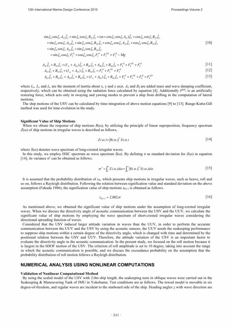
zz FFFFBAIBABA 6666666666664464262262 )( [13] where Ixx, Iyy and Izz are the moment of inertia about x, y and z axis. Aij and Bij are added mass and wave damping coefficient, respectively, which can be obtained using the radiation force calculated by equation [4]. Additionally FED
i is an artificially restoring force, which acts only in swaying and yawing modes to prevent a ship from drifting in the computation of lateral motions.
The ship motions of the USV can be calculated by time-integration of above motion equations [9] to [13]. Runge-Kutta-Gill method was used for time-evolution in the study.
Significant Value of Ship Motions When we obtain the response of ship motions R(ω), by utilizing the principle of linear superposition, frequency spectrum
Z(ω) of ship motions in irregular waves is described as follows,
)(S)(R)(Z 2 [14] where S(ω) denotes wave spectrum of long-crested irregular waves.
In this study, we employ ISSC spectrum as wave spectrum S(ω). By defining σ as standard deviation for Z(ω) in equation [14], its variance σ2 can be obtained as follows.
0
2
0
2 d)(S)(Rd)(Z [15]
It is assumed that the probability distribution of xR, which presents ship motions in irregular waves, such as heave, roll and
so on, follows a Rayleigh distribution. Following the relation between signification value and standard deviation on the above assumption (Fukuda 1986), the signification value of ship motions xR1/3 is obtained as follows.
002.23/1Rx [16]
As mentioned above, we obtained the significant value of ship motions under the assumption of long-crested irregular waves. When we discuss the directivity angle of acoustic communication between the USV and the UUV, we calculate the significant value of ship motions by employing the wave spectrum of short-crested irregular waves considering the directional spreading function of waves. Considered that the USV induced larger attitude variation in waves than the UUV, in order to perform the accurate
communication between the UUV and the USV by using the acoustic sensors, the UUV needs the seakeeping performance to suppress ship motions within a certain degree of the directivity angle, which is changed with time and determined by the positional relation between the USV and UUV. Therefore, the attitude variation of the USV is an important factor to evaluate the directivity angle in the acoustic communication. In the present study, we focused on the roll motion because it is largest in the 6DOF motion of the USV. The criterion of roll amplitude is set to 10 degree, taking into account the range in which the acoustic communication is possible, and we discuss the exceedance probability on the assumption that the probability distribution of roll motion follows a Rayleigh distribution. NUMERICAL ANALYSIS USING NONLINEAR COMPUTATIONS Validation of Nonlinear Computational Method
By using the scaled model of the USV with 2.0m ship length, the seakeeping tests in oblique waves were carried out in the Seakeeping & Maneuvering Tank of JMU in Yokohama. Test conditions are as follows. The towed model is movable in six degree-of-freedom, and regular waves are incident to the starboard side of the ship. Heading anglesχwith wave direction are
- 241 -
12th International Marine Design Conference 2015 Proceedings Volume 2

five cases, 180, 135, 90, 45 and 0 [deg], where the angle 180 [deg] means head sea, the ratio of wave length to ship length is from 0.4 to 3.0, then wave height is 0.04 [m], corresponding to Sea State 2, and in the present study the case of zero speed is reported. By carrying out the free oscillation model test, we obtained the extinction coefficient to determine roll damping in the case of zero speed. For the comparisons between the computational results and the experimental ones, RAO of ship motion are shown in Figure
4 to 8. In these figures, the computational results by linear strip theory based on STF (Salvesen, Tuck and Faltinsen 1970) methods are also shown as solid lines for references. All results are for the case that Froude number is zero (Fn=0.0). In whole computational results by nonlinear method show better agreements with experimental ones than those by linear method. Especially nonlinear results predict the wave length corresponding to the peak value for rolling amplitude, that is, the resonant frequency of roll motions better. This is because nonlinear method can take into account the change of restoring moment accurately and the roll damping due to the dome attached to the hull bottom adequately. In this study, we evaluate the amplitude of roll motion in the case of Fn=0.0 where the roll motion becomes the largest
Signification Value of Ship Motions
From above-mentioned validation tests, it was found that the present nonlinear method is better to predict the frequency response of the USV. So we can compute the variance for ship motions in irregular waves, based on the equation [15]. Here the present study tolerates the assumption that the principle of linear superposition is still valid even if nonlinear approach is
Figure 4: Ship motions of USV (χ=180 deg ) Figure 5: Ship motions of USV (χ=0 deg )
Figure 6: Ship motions of USV (χ=135 deg )
Figure 7: Ship motions of USV (χ=90 deg )
- 242 -
12th International Marine Design Conference 2015 Proceedings Volume 2

Figure 8: Ship motions of USV (χ=45 deg )
Table 2: Significant Value of Ship Motions
Heading (deg) Heave (m) Pitch (deg) Sway (m) Roll (deg) Yaw (deg) 180 0.094 3.301 0.000 0.000 0.000 135 0.105 2.725 0.061 6.386 1.012 90 0.112 0.175 0.093 9.684 0.113 45 0.109 2.007 0.053 5.618 0.839 0 0.102 2.567 0.000 0.000 0.000
employed for accurate hydrodynamic forces. Table 2 shows the signification value of ship motions to the variation of heading angle to the wave direction. Because the signification value of roll motion in beam seas (χ=90deg.) is largest in all wave directions, the guideline that the directivity angle of acoustic communication between USV and UUV should be decided in consideration of roll motion in beam sea. In the underwater communication system between the USV and UUV, the area exists, where each vehicle can send and
receive data mutually. So the USV and UUV need to keep their position optimal within a certain range in vertically parallel running in waves. Nonlinear Effects of Wave Height on Roll Motion
The amplitude of roll motion in actual seas must be estimated accurately to decide the directivity angle of acoustic communication. Sea condition in operating the USV is a wide range of variations, for example, in calm condition, in turns, severe condition. Therefore, we need to investigate the effect of the wave height on roll motion to estimate the amplitude of roll motion accurately.
Numerical studies on roll motion are implemented under the condition of beam sea, with the wave height changed in the three cases of 0.06, 0.13, and 0.26m. The wave height is chosen in considering that the draft of the hull part after the removal of the dome at bottom is 0.303m. The roll motion response computed with wave height changed is shown in Figure 9. Figure shows the tendency that the amplitude of roll
motion in the vicinity of peak value becomes smaller as the wave height increases, on the other hand, in the range except for the wave length where rolling gives the maximal amplitude, the amplitude of roll motion does not vary even if the wave height increases. In view of the present studies, the effect of the wave height has to be taken into account for the evaluation of the maximal roll motion. Moreover it is confirmed that nonlinear strip method presented in this paper is valid to estimate the lateral motion of the USV.
Figure 9: Effect of wave height on roll motion (χ=90 deg )
- 243 -
12th International Marine Design Conference 2015 Proceedings Volume 2

EFFECTS OF DOME CONFIGURATION ON ROLL MOTION Dome Attached at Bottom of USV
For the dome attached with bottom of the USV in this study, the configuration of the cross section is wing section of NACA0015 which has been utilized widely in the aircraft. Its configuration is anterior-posterior asymmetry, and is blunt at the leading edge. In the marine vessel, Arc blade whose configuration is longitudinal symmetries has been utilized widely from view point of study for maneuverability.
In this paper, we consider three kinds of shapes for the dome attached with the bottom of the USV to investigate the effect on the amplitude of roll motion. At first, we employ the dome whose cross section is arc blade and is equal to the length and draft of present dome. This dome is named Type A. Next, the configuration of cross section is equal to one of Type A, and the draft is large than one of Type A to increase the viscous roll damping. This dome is named Type B. Figure 10 shows the configuration of dome at the bottom of the USV.
In this study, we carried out the free oscillation test to obtain extinction coefficient. As for the extinction coefficient of Type A and Type B, we obtained it by using Watanabe’s formula (1957). Table 3 shows these extinction coefficient to calculate the roll damping.
Figure 10: Configuration of the dome at bottom of USV
Table 3: Extinction coefficient
Distinction coefficient Original shape Type A Type B a 0.0851 0.0870 0.1391 b 0.0179 0.0231 0.0340
Effects of Dome Configuration on Roll Motion
Figure 11 show the computational results of the roll amplitude with variation of the dome configuration. Ship speed is for the case of Fn=0.0, and wave height is 0.13m. According to these results, it is found that at the amplitude of roll motion for NACA0015 is coincided with one of Type A. The reason is why these extinction coefficients are almost the same. In both domes, the length and draft are equal, although the shape of cross section is different. On the other hand, the amplitude of roll motion for Type B is quantitatively different from that of the others. Additionally the peak value of roll amplitude for Type B is the smallest. The draft of Type B is larger than that of the others, and the roll damping of Type B must be largest. Therefore Type B shows the smallest peak value of roll amplitude. Figure 12 shows the signification value of roll amplitude for three kinds of configuration with variation of wave height. The
signification value of roll amplitude of the Original (NACA0015) corresponds to one of Type A, because these responses for roll motion is almost the same, and the signification value of Type B is the smallest in all configurations because the roll damping force becomes strongest.
TypeB TypeA Original shape
<Cross section>
<Side view>
NACA0015
- 244 -
12th International Marine Design Conference 2015 Proceedings Volume 2

Figure 11: Roll amplitude with variation of dome Figure 12: Signification value of roll amplitude with -configuration variation of wave height
CONCLUSIONS
In this study, we developed the computational method based on nonlinear strip method to investigate the motion characteristics of the USV, and investigated the effect of wave height and of shape of the dome attached with the bottom of the USV on roll motion to estimate the roll amplitude, which is necessary to decide the directivity angle of acoustic communication between the USV and the UUV.
To validate our nonlinear method, we compared the results for ship motions by the present method with those by the tank test and linear strip method. In those results, it was confirmed that the present method was more effective than linear strip method to estimate ship motions in oblique waves.
The present studies gave the tendency that roll amplitude becomes smaller as the wave height becomes larger in the vicinity of the peak value of roll motion. It is clarified that the effect of wave height for roll amplitude becomes strong in the vicinity of the peak value of roll motion. In the case that the principal dimensions for length and draft are the same, the dome configuration does not affect the roll amplitude much, even if the shape of cross section is changed. However, with the principal dimensions varied, the characteristics of roll motion take on a new aspect.
REFERENCES DOBASHI, J. “Estimation method for ship motions of unmanned surface vehicles in real seas.” Rep. No.7154, Technical report, Technical Research and Development Institute, Ministry of Defense of Japan (2014) FUKUDA, J. “Theoretical determination of design wave bending moments.” Japan Shipbuilding Marine Engng, 2 (1967):13-22. KABA, H. “The Study of Unmanned Underwater Vehicles in Naval Systems Research Center of TRDI.” RDEFENSE TECHNOLOGY JOURNAL, DEFENSE TECHNOLOGY FOUNDATION, 406 (2015):14-22. KUNUGI,Y. , KIHARA, H. and SETO, H. “On nonlinear hydrodynamic forces in time-domain analysis of ship motions.” Conference Proceedings of the Japan Society of Naval Architects and Ocean Engineers, 13 (2011):185-188. OGILVIE, T.F. and TUCK, E.O. “A rational strip theory of ship motions.” Rep. No.13, Department of Naval Architecture and Marine Engineering, University of Michigan (1969) SALVESEN, N., TUCK, E.O. and FALTINSEN, O.M. “Ship motions and sea load.” Trans SNAME, 78 (1970):250-287. WATANABE, K. and INOUE, M. “On the computational method of roll damping, so-called rolling N of ships.( in Japanese)” Journal of The West-Japan Society of Naval Architects, 14 (1957): 39-48.
- 245 -
12th International Marine Design Conference 2015 Proceedings Volume 2

YAMAMOTO, Y., FUJINO. M. and FUKASAWA, T. “Motion and Longitudinal Strength of a Ship in Head Sea and the Effects of Non-Linearities.” Journal of the Society of Naval Architects of Japan, 143 (1978):179-187.
- 246 -
12th International Marine Design Conference 2015 Proceedings Volume 2