on the study of ricochet and penetration in sand, water...
TRANSCRIPT

On the study of ricochet and penetration in sand, water and gelatin byspheres, 7.62 mm APM2, and 25 mm projectiles
John F. MOXNES a,*, Øyvind FRØYLAND a, Stian SKRIUDALEN a, Anne K. PRYTZ b,Jan A. TELAND a, Eva FRIIS b, Gard ØDEGÅRDSTUEN b
a Land Systems Division, Norwegian Defence Research Establishment, P.O. Box 25, NO-2027 Kjeller, Norwayb Nammo Raufoss AS, P.O. Box 162, NO-2831 Raufoss, Norway
Received 4 August 2015; revised 16 December 2015; accepted 17 December 2015
Available online 8 January 2016
Abstract
We examine the ricochet and penetration behavior in sand, water and gelatin by steel spheres, 7.62 mm APM2 and 25 mm projectiles. Athreshold impact angle (critical angle) exists beyond which ricochet cannot occur. The Autodyn simulation code with the smooth particlehydrodynamic (SPH) method and Impetus Afea Solver with the corpuscular model are used and the results are compared with experimental andanalytical results. The resistance force in sand for spheres was proportional to a term quadratic in velocity plus a term linear in velocity. The dragcoefficient for the quadratic term was 0.65. The Autodyn and Impetus Afea codes simulate too large penetration due to the lack of a linear velocityresistance force. Critical ricochet angles were consistent with analytical results in the literature. In ballistic gelatin at velocities of 50–850 m/s adrag coefficient of 0.30 fits the high speed camera recordings if a linear velocity resistance term is included. However, only a quadratic velocityresistance force with drag coefficient that varies with the Reynolds number also fits the measurements. The simulation of a sphere in water withAutodyn showed too large drag coefficient. The 7.62 mm APM2 core simulations in sand fit reasonable well for both codes. The 25 mm projectilericochet simulations in sand show consistency with the high speed camera recordings. Computer time was reduced by one to two orders ofmagnitudes when applying the Impetus Afea Solver compared to Autodyn code due to the use of the graphics processing units (GPU).© 2016 China Ordnance Society. Production and hosting by Elsevier B.V. All rights reserved.
Keywords: Ricochet; Simulation; Sand; Gelatin; Autodyn; Impetus Afea Solver; Smooth particle; Sphere
1. Introduction
Ricochet occurs when the final velocity vector of the centerof mass of a projectile is oriented away from the target and isassociated with small impact angles or high obliquity (obliquityis defined as the angle between the normal surface vector andthe velocity vector of the center of mass of the projectile). Thericochet angle and the ricochet velocity are dependent on theimpact velocity, obliquity angle, yaw, mass of the projectile,geometry, moment of inertia and target properties. A thresholdimpact angle (critical angle) exists beyond which ricochetcannot occur. However, the relationship between critical impactangle, projectile nose shape, amount of water, mineralogy andimpact velocity is still not fully understood [1].
1.1. Sand
Sand grain failure in front of the projectile may be an impor-tant energy dissipation mechanism in sand. Very fine whitepowder is observed in the wake of the projectile due to thepulverization in front of the projectile. It has been estimatedthat 8% of the energy of the projectile was consumed in pul-verization of the individual sand particles in hypersonic sandpenetration experiments [2]. The yield point during compress-ing of aggregate sand can be correlated to the initiation ofparticle failure [3]. When sand is under loading it undergoes achange in shape and compressibility. The volume decreases dueto changes in grain arrangements where microscopic interlock-ing with frictional forces between interacting particles lead tobending of flat grains and rolling of rounded particles. If theload is further increased, the grains eventually become crushed.High pressure compression tests have revealed differenttypes of damage mechanisms, (a) single abrasion fracture,(b) multiple abrasion fractures, (c) major splitting of particlesinto two or more particles, (d) breakage of sub particles,
Peer review under responsibility of China Ordnance Society.* Corresponding author. Tel.: +47 63 807514.
E-mail address: [email protected] (J.F. MOXNES).
http://dx.doi.org/10.1016/j.dt.2015.12.0042214-9147/© 2016 China Ordnance Society. Production and hosting by Elsevier B.V. All rights reserved.
Available online at www.sciencedirect.com
Defence Technology 12 (2016) 159–170www.elsevier.com/locate/dt
H O S T E D BY
ScienceDirect

(e) pulverization of particles into many small pieces. However,under high rate compressive loading, the only mode of failureobserved was pulverization, Parab et al. [4]. At very low veloci-ties frictional resistance exceeds hydrodynamic resistance.At projectile velocities above the speed of sound in the sand,particles may lock up instead of flowing locally. However, lockup of particles may depend on the density. The difference inresponse for high and low velocity is related to the timescalerequired for relaxation of force chain structures. A comprehen-sive review of the response of granular media to rapid penetra-tion was recently published by Omidvar et al. [5].
1.2. Modeling
Modeling by discrete element methods may require exten-sive material parameters at high strain rates, large strain, andhigh pressure. Use of simple analytical models is thus for somecases a viable alternative. When the deformation of the projec-tile is negligible the rigid body assumption can be applied. Forlinear projectile trajectories Robins [6] and Euler [7] assumedthat for sand the force was a constant. Poncelet [8] set the forceequal to a constant plus a term proportional to the square of thevelocity. Resal [9] set the force proportional to the velocity plusa term proportional to the square of the velocity. Forrestal andLuk [10] applied a force that was a constant plus a term pro-portional to the square of the velocity based on the cavityexpansion theory. Agreement within 19% was shown whencomparing with experimental results. Allen et al. [11] devel-oped a model where an abrupt transition in drag force occurs atthe critical velocity, of about 100 m/s, believed to be due totransition from inelastic to quasi-elastic impacts. Projectileswith nose cone angles from 180 to 90° were stable. Forpenetration problems with relative large obliquity, yaw orpitch, nonlinear motion is expected and the projectile mayeven reverse its motion toward the target surface (ricochet).However, even for very small yaw, or obliquity, instability mayoccur and the trajectory becomes curved. Soliman et al. [12]studied many years ago spherical projectile ricochet in waterand sand theoretically and experimentally. For water and sand itwas found that the ricochet angle was around 20% larger thanthe impact angle. Bernard et al. [13] show that the trajectorywent from linear to curved when the impact velocity wasincreased from 427 to 512 m/s for 3.7° obliquity. Above 30°obliquity the trajectory was curved and the projectile mightmove towards the target surface when the projectile’s slender-ness ratio L/D (length to the diameter of the projectile) wasreduced. Projectiles with nose cone angles less than 90°become progressively more unstable with decreasing coneangle. For sand it was found that the critical angle decreaseswith increasing velocity but a cut-off angle was found.
Daneshi and Johnson [14,15], studied ricochet of sphericaland dumb-bell shaped projectiles in sand and found that thevolume of sand displaced from the crater was proportional tothe initial momentum of the projectile. Bai and Johnson [16]examined the effect of projectile speed and medium resistanceon ricochet in sand. Johnson et al. [17] examined the effect ofhigh velocity oblique impact and ricochet of mainly long rodprojectiles. Savvatteev et al. [18] examined high-speed (up to
4000 m/s) penetration into sand. Full melting of the steel bulletsoccurs at the velocity of 1800–2000 m/s. Anderson et al. [19]studied the flow field center migration during vertical andoblique impacts. Reducing the friction between grains and pro-jectile increases stability [20]. Bless et al. [21] found that ahemi spherical nose gave less resistance and that projectileswere stabilized by fins. Nishida et al. [22] examined the effectof sand density and projectile diameter on critical incidentangles of projectiles impacting granular media. The criticalreverse velocity is the velocity where the projectile starts tomove back to the surface of the target. Li and Flores-Johnson[23] investigated the trajectory in soil penetration by imple-menting a resistance function based on the cavity expansiontheory into ABAQUS code. It was found that the critical reversevelocity decreases with increasing obliquity and that tumblingof the projectile increases with the ratio Lc/L, where Lc is thedistance from the nose of the projectile to the center of massand L is the length. Ye et al. [24] studied the influence ofprojectile rotation on the oblique penetration in granular media.See Johnson et al. [17] for a review of high velocity oblique andimpact ricochet.
Impacts on gelatin show significantly different displacementfields compared to sand [25]. See also Wen et al. [26] for impactof steel spheres in gelatin at moderate velocities.
Rigorous hydrocode calculations can offer insight into thephysics of ricochet. Numerical models have increasingly beenused in analysis of projectile penetration into soils and granularmaterials due to the inherent complexity of the problem. Soil orsand can be considered as a three phase medium consistingmainly of solid grains, with portions of water and air. Moxneset al. [27] proposed a continuum MO-granular model whereparameters are constructed by using a quasi-static unilateralcompression test, and validated by using a high-speed piston(up to 300 m/s) impacting a granular pyrotechnic bed. Thepiston and the tube were made of lexan, which made it possibleto record the piston position and the compaction wave propa-gating in front, by using a high-speed camera. The experimentalrecordings were compared to numerical simulations, using theexplicit numerical code Autodyn-2D, and a new constitutivematerial model for the porous material. The models apply ahydrostatic compaction curve as a function of the density, amodel for the yield stress as a function of pressure and elasticmodulus as a function of density. The model does not includeany strain rate dependency of yield stress. This is an assumptionthat may be good as long as the strain rate is above 103/s [28].For a review of stress–strain behavior of sand at high strainrates, see Omidvar et al. [29]. Laine and Sandvik [30] derivedquasi static tri-axial material parameters for dry sand using theMO-granular continuum model implemented in Autodyn. Themodel applies when soil packing density is sufficient high andhence the particle–particle contacts are semi-permanent. Weagree with Grujicic et al. [31] that this is the widely used soilmodel in military communities and it has been widely used forshock simulation involving dry sand within the Autodyn com-munity with quite decent results, e.g. for determining blast loadfrom buried mines [32,33]. However, the model also has beenused in civil applications such as road side safety [34]. The
160 J.F. MOXNES et al. /Defence Technology 12 (2016) 159–170

model provides a good compromise between the inclusion ofessential physical phenomena reflecting material responseunder dynamic loading and computational simplicity [31].
The elastic unloading wave in sand travels faster than theplastic compaction wave, which leads to fast attenuation andenergy absorption of the propagating wave. Recently Laine andLarsen [35] presented a model where the elastic bulk modulusis both a function of the density and pressure. This modificationcaptures more properly the non-linear behavior seen in tri-axialtest data during unloading. The modification results in a moreaccurate shock wave propagation and attenuation in dry sand.The parameters of Laine and Sandvik [30] were developedessentially for dry sand, and it has to be modified by moisturecontent. The dry sand material parameters underpredict themagnitude of transferred impulse at high levels of moisture(roughly above 10%) due to too high compressibility of sandthat promotes energy dissipating through irreversible compac-tion of the sand, and lack of consideration of the reduction ofthe yield stress due to moisture induced inter-particle lubrica-tion effects. Recently Grujicic et al. [31,36] developed a modi-fied version of the Moxnes et al. [27] model with the Laine andSandvik [30] parameters to account for moisture content. Theessential changes are that the compaction curve, yield stressand the elastic modulus are parameterized by the degree ofwater saturation. A somewhat improved agreement with theexperimental results was obtained. For three phase models, seeWang et al. [37], Grujicic et al. [31,36], and Zakrisson et al.[38]. Tong and Tuan [39] used a visco-plastic model with theDrucker–Prager yield criterion for the solid phase along withthe capacity of incorporating damage. Higgins et al. [40] devel-oped a model for high strain rate based on the concepts ofcritical-state soil mechanics.
Although, it is most common to model heterogeneous mate-rials such as sand or powder as a continuum, in so doing theheterogeneous nature of the material and grain interaction arelost. With the continued development of massive computerarchitectures and parallel processing techniques, sufficientlylarge domains and high resolution simulations of these hetero-geneous materials are feasible such that each grain is assignedmaterial properties. See Andò et al. [41] for recent attempts totrack discrete particles and [20,42,43] for a study on two andthree dimensional meso-scale simulations.
Deshpande et al. [44] developed a constitutive model, basedon the approach proposed by Bagnold [45], for high-rate defor-mation of an aggregate of monosized rigid spherical particles(corpuscles) that collide and interact by damping and friction.Those particles are not necessarily of the same size as the sandparticles. This discrete theory focus on the response of a looseaggregate, particular relevant to ejecta from shallow-buriedexplosives and the loading structures by high velocity spray oflow density soil. The corpuscular approach for sand was furtherdeveloped by Børvik et al. [46] by combining with an earlierdeveloped corpuscular approach for gases [47,48]. Andersonet al. [49] provided a comprehensive review of the literaturerelated to mine blast and also performed a series of mine blastloading experiments that provide data for numerical simula-tions and validations of constitutive models. Johnson et al. [50]
presented a hybrid particle-finite element algorithm for highvelocity impact. Børvik et al. [51] examined the penetration ofgranular materials by small-arms bullets. The corpuscularapproach was used for the sand. A random disturbance wasintroduced due to the numerical particle stacking. Good agree-ment with experimental results was achieved.
In section 2 we study experimental and simulation results insand, gelatin, and water; both during penetration and ricochet.Section 3 concludes.
2. Penetration and ricochet in sand by spheres and 7.62APM2 projectiles
2.1. Sand
Fig. 1 shows the particle distribution of two different sandtypes. The Nammo and Børvik et al. [51] sand have much thesame distribution. The sand used by Laine and Sandvik [30] issimilar we believe. In the Autodyn simulation we use theMO-granular model with the Laine and Sandvik [30] param-eters. In Impetus Afea Solver we use the parameters of Børviket al. [51] and the corpuscular theory. The sand bed sizes areidentical in Autodyn and Impetus Afea Solver simulations.
2.2. Numerically
The projectiles are assumed to be rigid, while the target ismodeled using smooth particle hydrodynamics (SPH) inAutodyn. In Impetus Afea Solver we, in addition to the rigidmodel, also use an elastic model of the projectiles. The target ismodeled by the corpuscular theory. All simulations in ImpetusAfea Solver are run in full 3D, while in Autodyn 3D with halfsymmetry is chosen.
2.3. Sphere
A steel sphere of radius a = 0.6 cm is shot into sand atthe impact velocity of 850 m/s and zero obliquity. The densityof the sand is 1.82 g/cm3. The simulations use a bed sizeof 25 cm × 4.8 cm × 4.8 cm. Particle size is 0.1 cm. Themaximum penetration distance was recorded to be 18 cm [18].Fig. 2 shows the simulated position vs time. Both the Autodynand the Impetus Afea Solver simulate a somewhat toolarge penetration position, and the velocity is not zero at the
Fig. 1. The remaining mass fraction of the sand as a function of the sieve size.
161J.F. MOXNES et al. /Defence Technology 12 (2016) 159–170

penetration distance of 18 cm. We apply an analytical modelwhich gives that the sphere stops at some distance. The resis-tance force is assumed to be proportional to a sum of a qua-dratic and linear term in the velocity [9], to read
d
dd
c
c
d
v
t
v
mC Av
v v
v
v
mC A
A a
= − − = − −
= =
τρ
τ τ
τρ
1
2
11
2
22
2, π(1)
ρ is the density of sand, a is the radius of the sphere,and Cd is the drag coefficient. vc is a parameter with the unit ofvelocity while τ is a parameter with dimension time. A is theprojected area of the sphere. The solution of Eq. (1) can bewritten [52]
v tv v
v v Exp t v
x t vv
vt
( ) =+( ) ( )−
( ) = + − −( )(⎛⎝⎜⎜⎜
0
0 0
01 1
c
c
cc
Ln Exp
τ
τ τ⎞⎞⎠⎟⎟⎟
( ) = +( ) − ( )( )−v x v v Exp x v v0 c c cτ
(2)
It is easily verified that the maximum penetration length L is
v x L vv
v( ) = ⇒ = +
⎛⎝⎜⎜⎜
⎞⎠⎟⎟⎟0 1 0
cc
Lnτ (3)
Without the linear resistance term an infinite maximumpenetration length is achieved. Interestingly, this solutionwithout the linear velocity resistance term fits to the Autodynsolution for all times when Cd =1 1. . We fit the solution in Eq. (2)to τ and Cd (or vc) such that the maximum penetration length is18 cm and thus in agreement with the experiments (Fig. 2). Butno unique solution exists for the two parameters. However,Savvatteev et al. [18] also applied impact velocities of 1300 m/sand 1580 m/s without significant deformation or melting of thesphere. The maximum penetration length was 22 cm and 24 cmrespectively. Using these results we find that τ = × −5 65 10 4. sand Cd = 0 65. fits well to the three shooting velocities. However,
a problem with the solution is that only at infinite time does thesolution reach the maximum penetration length. By adding asmall resistance term of γ = −500 2m s on the right hand sideof Eq. (1) [11], the solution is approximately the same butreaches the final penetration length in finite time.
Impetus Afea Solver results in penetrations larger thanin Autodyn (Fig. 2). Applying elastic or a rigid model forthe sphere does not influence the results significantly.When increasing particle number from 1 million (baseline)to 5 million the simulated position increases. The position issignificantly reduced when applying friction (μ) betweenthe sphere and the sand, and fits the Autodyn result withoutfriction. In a newly developed sand model a cap is introducedin the Impetus Afea Solver (Appendix B). Here the frictionforce between the sand particles saturates at high contact forces.We apply the baseline parameters μ ηs s= =0 8 0 008. , . , andμ = 0 2. (Fig. 2).
We define the effective drag coefficient by
Cm
v
t
Avd
d
d* = −1
22ρ
(4)
Using Eq. (1) the effective drag coefficient is easily shown tobe C C m C A vd d d* = + ( )( )1 2 ρ τ . Thus the effective drag coef-ficient is increasing with decreasing velocity. Fig. 3 shows thedifferent drag coefficients. Autodyn has larger drag coefficientthan Impetus Afea Solver and the drag is almost equal to thedrag coefficient in Impetus Afea Solver applying a frictioncoefficient of 0.5 between the sphere and the sand. The analyti-cal model in Eq. (2) shows that the effective drag coefficientincreases with decreasing velocity. However, since the velocityof the sphere decreases very fast, the drag coefficient at largertimes does not influence the velocity very much (Fig. 4).
Fig. 5 shows the simulations in Autodyn for the steel sphere.It is notable that to simulate the drag the width of the sand beddoes not need to be very much larger than the sphere. However,to simulate the correct sand cavity (which is not an issue here)the width of the bed has to be much larger. Larger bed increasesthe computer time.
Fig. 2. The position x vs time for a steel sphere with radius a = 0.6 cm pen-etrating sand. The impact velocity is 850 m/s. Horizontal dashed line is mea-surement of the maximum penetration distance of 18 cm.
Fig. 3. The different drag coefficients as a function of velocity simulated byAutodyn and Impetus Afea Solver.
162 J.F. MOXNES et al. /Defence Technology 12 (2016) 159–170

By applying pressure in front of the sphere ofp v K= +1 2 2ρ , it can be shown that the critical ricochetangle is [16]
θ ρρ ρc
s
= +⎛
⎝⎜⎜⎜
⎞
⎠⎟⎟⎟⎟−
1
10
42 2
K
v
ag
v(5)
where ρs = is the density of the sphere. It is easily verified thatthe term with the acceleration of gravity g is negligible. Weset K equal to the flow stress in sand that depends on thehydrodynamic pressure 1 2 2ρv . For the velocity of 850 m/s
the hydrodynamic pressure is 3.6 × 10⁸ Pa. Thus the flowstress K is 226 MPa (Appendix A). Inserting into Eq. (5)gives the critical angle of 14° for the steel sphere of densityρ = 7 8 3. g cm . For water K = 0, ρ =1 0 3. g cm , and weachieve 6° critical angle. Figs. 6 and 7 show the result for twodifferent impact angles. The results are consistent with theanalytical model in Eq. (5).
As a further test on the numerical simulations and the ana-lytical model we numerically shot the sphere into water. Theresults are consistent with the analytical theory as seen inFigs. 8 and 9. However, a closer examination of the drag coef-ficient, addressed later in this article, shows that Autodyn simu-lates too large drag coefficient.
We shot a steel sphere of radius a = 0.25 cm into ballisticgelatin that had the mass fraction of 90% water and 10%gelatin. The density was 1.02 g/cm3. The simulation bed iscylindrical with diameter 2.5 cm and length 20 cm. The SPHparticle size in the bed is 0.5 mm.
Gelatin has been modeled as an elastic plastic material withyield strength of Y [Pa] = 2.2 × 10⁵ + 1.9 × 10⁴ εp where εp isthe effective plastic strain [26]. However, the strength is smallcompared to the overall hydrodynamic pressure and we neglectit together with any strain rate dependency.
Fig. 10 shows the position vs time for three different impactvelocities. A resistance force quadratic in velocity with constantdrag coefficient does not fit to the experiments (results notshown). However, if we use the linear term resistance velocity
Fig. 4. The velocity vs time for a steel sphere with radius a = 0.6 cm penetrat-ing sand. The impact velocity is 850 m/s.
Fig. 5. Penetration of a steel sphere of radius a = 0.6 cm in sand. Impact velocity is 850 m/s (Autodyn).
Fig. 6. Ricochet of a steel sphere of radius a = 0.6 cm in sand. Impact velocity is 850 m/s and impact angle is 10° (Autodyn).
163J.F. MOXNES et al. /Defence Technology 12 (2016) 159–170

term with τ = 0 00219. s and vc m s= 80 16. (which gives theCd of 0.3) in Eq. (1) a good fit is achieved as shown by theanalytical results in Fig. 10. However, the viscosity of gelatinis much larger than for water and thus the Reynolds number ismuch smaller for the same velocity. The Reynolds number isRe va= ρ η , where η is the viscosity. In the range 103–3 × 10⁵ the drag coefficient of a sphere in a fluid is known to be0.47. The drag coefficient of a sphere is 0.2 when the Reynoldsnumber is larger than 3 × 10⁵. We set that v = 850 m/s,a = 0.25 cm, ρ =1 0 3. g cm , and η = −10 3 Pa s for water. Thisgives Re = 2 × 10⁷ in water, and a constant drag coefficient of0.2 is to be expected. However, the viscosity of gelatin may bemore like honey or ketchup say 0.1–10 Pa s as our suggestion
(https://en.wikipedia.org/wiki/Viscosity). We use that the dragcoefficient is dependent of the Reynolds number [53] and setthat C C Re C vad d d= ( ) = ( )ρ η . Next we solve Eq. (1) numeri-cally with τ = infinite. The viscosity η is chosen to match themeasurements. We find that η = 0 5. Pa s gives a good fit to theexperiments as seen by the numerical solution in Figs. 10.Fig. 11 shows the velocity vs time. We see that the camerarecordings span the velocity range of 50–884 m/s.
Fig. 12 shows the effective drag coefficient in gelatin. TheAutodyn simulates too large drag coefficient both for the SPHand an Eulerian grid in the target when applying a water modelas a substitute. This may suggest that even for gelatin, thatshows much lower Reynolds number than water, a turbulence
Fig. 7. Penetration of a steel sphere of radius a = 0.6 cm in sand. Impact velocity is 850 m/s and impact angle is 15° (Autodyn).
Fig. 8. Ricochet of a steel sphere of radius a = 0.6 cm in water. Impact velocity is 850 m/s and impact angle is 5° (Autodyn).
Fig. 9. Penetration of a steel sphere of radius a = 0.6 cm in water. Impact velocity is 850 m/s and impact angle is 10°.
164 J.F. MOXNES et al. /Defence Technology 12 (2016) 159–170

model is needed to reduce drag. Adding strain or strain ratedependency to the constitutive equation will increase the dragcoefficients even more. We believe. However, the model andsolver to be used in Autodyn to simulate the correct drag inwater and in ballistic gelatin is uncertain.
Fig. 13shows the experimental results for the sphere and thecavity in gelatin. The experimental sphere is 2.7 cm ahead ofthe simulated sphere when using SPH and the water model as amodel for gelatin. When using the Eulerian grid for gelatin the
Fig. 10. Position vs time for a steel sphere of radius a = 0.25 cm penetratinginto gelatin at different impact velocities. Exp shows high speed camera mea-surements. Num. is the numerical solution with the drag coefficient varyingwith the Reynolds number.
Fig. 11. Velocity vs time for a steel sphere of radius a = 0.25 cm penetratinginto gelatin at different impact velocities. Num. is numerical solution with dragcoefficient varying with the Reynolds number.
Fig. 12. The effective drag coefficient for a steel sphere of radius a = 0.25 cmpenetrating into gelatin. The impact velocity is 884 m/s.
Fig. 13. Simulated and experimental results of a sphere with radiusa = 0.25 cm penetrating into gelatin. The impact velocity is 884 m/s. The mea-sured sphere (blue) is ahead of the simulated sphere in Autodyn SPH (green)with 2.7 cm. Using the Eulerian grid for gelatin the measured sphere is aheadof the simulated sphere with 1.7 cm.
Fig. 14. The x-position vs time of a 7.62 mm APM2 core penetrating into sand.Impact velocity is 917 m/s.
Fig. 15. The x-velocity vs time of a 7.62 mm APM2 core penetrating into sand.Impact velocity is 917 m/s.
165J.F. MOXNES et al. /Defence Technology 12 (2016) 159–170
position of the simulated sphere is 1.7 cm behind the experi-mental position of the sphere.
2.4. 7.62 mm APM2
7.62 mm APM2 projectiles have been fired into sand byBørvik et al. [51]. The density of the sand was 1.73 g/cm3. Inthe Autodyn simulation the sand bed is cylindrical with diam-eter 15 cm and length 30 cm. SPH particle size is 1.82 mm. We
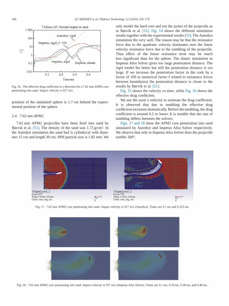
only model the hard core and not the jacket of the projectile asin Børvik et al. [51]. Fig. 14 shows the different simulationresults together with the experimental results [51]. The Autodynsimulation fits very well. The reason may be that the resistanceforce due to the quadratic velocity dominates over the linearvelocity resistance force due to the tumbling of the projectile.Thus effect of the linear resistance term may be muchless significant than for the sphere. The elastic simulation inImpetus Afea Solver gives too large penetration distance. Therigid model fits better but still the penetration distance is toolarge. If we increase the penetration factor in the code by afactor of 100 (a numerical factor f related to resistance forcesbetween boundaries) the penetration distance is closer to theresults by Børvik et al. [51].
Fig. 15 shows the velocity vs time, while Fig. 16 shows theeffective drag coefficient.
We use the axial x-velocity to estimate the drag coefficient.It is observed that due to tumbling the effective dragcoefficient increases dramatically. Before the tumbling, the dragcoefficient is around 0.5 or lower. It is notable that the rate oftumbling differs between the solvers.
Figs. 17 and 18 show the APM2 core penetration into sandsimulated by Autodyn and Impetus Afea Solver respectively.We observe that only in Impetus Afea Solver does the projectiletumble 360°.
Fig. 16. The effective drag coefficient in x-direction for a 7.62 mm APM2 corepenetrating into sand. Impact velocity is 917 m/s.
Fig. 17. 7.62 mm APM2 core penetrating into sand. Impact velocity is 917 m/s (Autodyn). Times are 0.1 ms and 0.325 ms.
Fig. 18. 7.62 mm APM2 core penetrating into sand. Impact velocity is 917 m/s (Impetus Afea Solver). Times are 0.1 ms, 0.18 ms, 0.38 ms, and 0.48 ms.
166 J.F. MOXNES et al. /Defence Technology 12 (2016) 159–170
2.5. 25 mm APEX projectiles
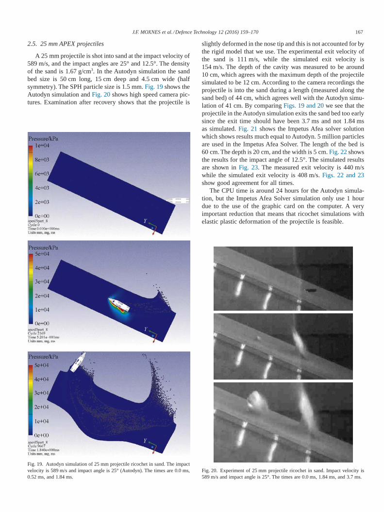
A 25 mm projectile is shot into sand at the impact velocity of589 m/s, and the impact angles are 25° and 12.5°. The densityof the sand is 1.67 g/cm3. In the Autodyn simulation the sandbed size is 50 cm long, 15 cm deep and 4.5 cm wide (halfsymmetry). The SPH particle size is 1.5 mm. Fig. 19 shows theAutodyn simulation and Fig. 20 shows high speed camera pic-tures. Examination after recovery shows that the projectile is
slightly deformed in the nose tip and this is not accounted for bythe rigid model that we use. The experimental exit velocity ofthe sand is 111 m/s, while the simulated exit velocity is154 m/s. The depth of the cavity was measured to be around10 cm, which agrees with the maximum depth of the projectilesimulated to be 12 cm. According to the camera recordings theprojectile is into the sand during a length (measured along thesand bed) of 44 cm, which agrees well with the Autodyn simu-lation of 41 cm. By comparing Figs. 19 and 20 we see that theprojectile in the Autodyn simulation exits the sand bed too earlysince the exit time should have been 3.7 ms and not 1.84 msas simulated. Fig. 21 shows the Impetus Afea solver solutionwhich shows results much equal to Autodyn. 5 million particlesare used in the Impetus Afea Solver. The length of the bed is60 cm. The depth is 20 cm, and the width is 5 cm. Fig. 22 showsthe results for the impact angle of 12.5°. The simulated resultsare shown in Fig. 23. The measured exit velocity is 440 m/swhile the simulated exit velocity is 408 m/s. Figs. 22 and 23show good agreement for all times.
The CPU time is around 24 hours for the Autodyn simula-tion, but the Impetus Afea Solver simulation only use 1 hourdue to the use of the graphic card on the computer. A veryimportant reduction that means that ricochet simulations withelastic plastic deformation of the projectile is feasible.
Fig. 19. Autodyn simulation of 25 mm projectile ricochet in sand. The impactvelocity is 589 m/s and impact angle is 25° (Autodyn). The times are 0.0 ms,0.52 ms, and 1.84 ms.
Fig. 20. Experiment of 25 mm projectile ricochet in sand. Impact velocity is589 m/s and impact angle is 25°. The times are 0.0 ms, 1.84 ms, and 3.7 ms.
167J.F. MOXNES et al. /Defence Technology 12 (2016) 159–170

3. Conclusions and discussion
We have examined the ricochet and penetration behaviorin sand and gelatin by steel spheres, 7.62 APM2, and 25 mmprojectiles. The Autodyn simulation code with the SPH method,and the Impetus Afea Solver simulation code with the corpus-cular model are used and the results are compared with experi-mental and analytical results. The resistance force in sand forspheres was found to proportional to a quadratic term in veloc-ity plus a linear term in velocity. The drag coefficient for thequadratic resistance force was 0.65. The Autodyn and ImpetusAfea Solver codes simulate too large penetration. We suggestthat the reason is lack of a linear velocity resistance force.
Critical ricochet angles were consistent with analytical resultsin the literature. In ballistic gelatin we study the penetrationbehavior in the velocity range of 100–850 m/s. A drag coeffi-cient of 0.30 fits the high speed camera recordings if a linearvelocity resistance term is added. However, only a quadraticvelocity resistance force with drag coefficient that varies withthe Reynolds number also fits to the measurements. The vis-cosity in gelatin is much higher than in water and a goodestimate of the viscosity of gelatin is important due to the lowReynolds number numbers that gives Reynolds number depen-dency in the drag coefficient. The 7.62 mm APM2 core simu-lations in sand fit reasonable well for both codes. The tumblingrate essentially determines the penetration distance and linearvelocity resistance forces seem less important. The simulationof a sphere in water with Autodyn and SPH showed too largedrag coefficient. We believe that a turbulence model is neededto simulate the correct drag. The 25 mm projectile ricochetsimulations show consistency with the high speed camerarecordings although discrepancies were observed. Computertime was reduced by one to two orders of magnitudes whenapplying the Impetus Afea Solver compared to Autodyn codedue to the use of the graphic card on the computer.
Our thorough literature survey, combined with the advancednumerical modeling using different types of solvers gives new
Fig. 21. Impetus Afea Solver simulation of 25 mm ricochet in sand. The impactvelocity is 589 m/s and impact angle is 25°. The times are 0.0 ms, 0.53 ms, and1.85 ms.
Fig. 22. Experiment of 25 mm projectile ricochet in sand. Impact velocity is589 m/s and impact angle is 12.5°. The times are 0.0 ms, 0.3 ms, and 1.0 ms.
168 J.F. MOXNES et al. /Defence Technology 12 (2016) 159–170

insight to the mechanisms and the quite complex problem ofpenetration and ricochet in multi-phase media such as sand aswell as more homogeneous targets such as water and gelatin.Some confirming experiments were also made, and literaturevalues were also used for comparison with the analytical andnumerical results. It was interesting to see how the commonAutodyn model performs relative to the more modern andhigher order accurate Impetus Afea Solver one, and especiallyhow the computational performance of the latter appears to bemuch more efficient on the computer.
We believe that the observed discrepancies between simula-tion results and experimental results are due to the mathemati-cal models as such. The current continuum and corpuscularmodels in the literature for sand and gelatin needs more vali-dation and probably also further development. The significantreduction in computer time when applying the Impetus Afea
Solver, may in further studies, reveal the influence of projectiledeformation and varying impact velocities during a lager rangeof impact angles. This brings the problem treated to a higherlevel.
Acknowledgment
The authors appreciate the comments from Chief ScientistOve Dullum at Norwegian Defence Research Establishment,which have improved this paper.
Appendix A: MO granular model parameters
{Density [kg/m3], Pressure [Pa]}:{{1674, 0.0}, {1740, 4.58E+06}, {1874, 1.50E+07}, {1997,
2.92E+07}, {2144, 5.92E+07}, {2250, 9.81E+07}, {2380,1.79E+08}, {2485, 2.89E+08}, {2585, 4.50E+08}, {2671,6.51E+08}}
{Density [kg/m3], Sound speed [m/s]}:{{1674, 265.2}, {1746, 852.1}, {2086, 1721.7}, {2147,
1875.5}, {2300, 2264.8}, {2572, 2956.1}, {2598, 3112.2},{2635, 4600.0}, {2641, 4634.0}, {2800, 4634.0}}
{Pressure [Pa], Yield stress [Pa]}:{{0.0, 0.0}, {3.40E+06, 4.24E+06}, {3.49E+07, 4.47E+07},
{1.01E+08, 1.24E+08}, {1.85E+08, 2.26E+08}, {5.00E+08,2.26E+08}}
{Density [kg/m3], Shear modulus [Pa]}:{{1674, 7.69E+07}, {1746, 8.69E+08}, {2086, 4.03E+09},
{2147, 4.91E+09}, {2300, 7.77E+09}, {2572, 1.48E+10},{2598, 1.66E+10}, {2635, 3.67E+10}, {2641, 3.73E+10},{2800, 3.73E+10}}
Appendix B: The Impetus Afea cap model
The base line and the cap model in Impetus Afea set thefriction force between particles as
F F K Base line K N m
F F K Min R Ca
f s N s s s
f s N s s s
= = =
= = ( )μ μ δμ μ δ η
, ,
, ,
410
2
8
pp(B1)
For the baseline model μs = 0 1. . For the cap modelμs = 0 8. , ηs = 0 008. . R is the particle size.
References
[1] Pierazzo E, Melosh HJ. Understanding oblique impacts from experiments,observations, and modeling. Annu Rev Earth Planet Sci 2000;28:141–7.
[2] Braslau DJ. J Geophys Res 1970;75:3987–99.[3] Nakata Y, Hyodo M, Hyde AFL. Microscopic particle crushing of sand
subjected to high pressure one-dimensional compression. Soils Found2001;41:69–82.
[4] Parab ND, Claus B, Hudspeth MC, Black JT, Mondal A, Sun J, et al.experimental assessment of fracture of individual sand particles atdifferent loading rates. Int J Impact Eng 2014;8:14.
[5] Omidvar M, Iskander M, Bless S. Response of granular media to rapidpenetration. Int J Impact Eng 2014;66:60–82.
[6] Robins B. New principles of gunnery. Richmond, Surrey: RichmondPublishing Co. Ltd; 1972.
[7] Euler L. Neue grundsätze der artillerie. Berlin: Von B.G. Teubner; 1922.[8] Poncelet JV. Cours de Mécanique Industrielle. 1829.[9] Resal H. Sur la penetration d’un projectile dans les semifluids it les
solides, cr. 120:397–401. 1895.
Fig. 23. Impetus Afea Solver simulation of 25 mm ricochet in sand. The impactvelocity is 589 m/s and impact angle is 12.5°. The times are 0.0 ms, 0.3 ms, and1.0 ms.
169J.F. MOXNES et al. /Defence Technology 12 (2016) 159–170
[10] Forrestal MJ, Luk VK. Penetration into soil targets. Int J Impact Eng1992;12:427–44.
[11] Allen WA, Mayfield EB, Morrison HL. Dynamics of a projectilepenetrating sand. J Appl Phys 1957;28(3):370–6.
[12] Soliman AS, Reid SR, Johnson W. The effect of spherical projectile speedin ricochet off water and sand. Int J Mech Sci 1976;18:279–84.
[13] Bernard RS, Creighton DC. Projectile penetration in soil and rock:analysis for non-normal impact. Vicksburg, MS, USA: U.S. ArmyEngineer Waterways Experimental Station Structures Laboratory; 1979.p. 12–60. Technical Report SL-79-15.
[14] Daneshi GH, Johnson W. The ricochet of spherical projectiles off sand.Int J Mech Sci 1977a;19:491–7.
[15] Daneshi GH, Johnson W. The ricochet of dumb-bell shaped projectiles.Int J Mech Sci 1977b;19:555–63.
[16] Bai YL, Johnson W. The effect of projectile speed and medium resistancein ricochet in sand. J Mech Eng Sci 1981;23:69–75.
[17] Johnson W, Sengupta AK, Ghosh SK. High velocity oblique impact andricochet mainly of long rod projectiles: an overview. Int J Mech Sci1982;24(7):425–36.
[18] Savvatteev AF, Budin AV, Kolikov VA, Rutberg PG. High-speedpenetration into sand. Int J Impact Eng 2001;26:675–81.
[19] Anderson JLB, Schultz PH. Flow-field center migration during verticaland oblique impacts. Int J Impact Eng 2006;33:35–44.
[20] Dwivedi SK, Teeter RD, Felice CW, Gupta YM. Two dimensionalmesoccale simulations of projectile instability during penetration in sand.J Appl Phys 2008;104:083502.
[21] Bless SJ, Berry DT, Pedersen B, Lawhorn W. Sand penetration by highspeed projectiles. AIP Conf Proc 2009;1195:1361.
[22] Nishida M, Okumura M, Tanaka K. Effects of density ratio and diameterratio on critical angles of projectiles impacting granular media. GranularMatter 2010;12:337–44.
[23] Li QM, Flores-Johnson EA. Hard projectile penetration and trajectorystability. Int J Impact Eng 2011;38:815–23.
[24] Ye X, Wang D, Zheng X. Influence of particle rotation on the obliquepenetration in granular media. Phys Rev E 2012;86:061304.
[25] Collins AL, Addiss JW, Walley SM, Promratana K, Bobaru F, Proud WG,et al. The effect of rod nose shape on the internal flow fields during theballistic penetration in sand. Int J Impact Eng 2011;38:951–63.
[26] Wen Y, Xu C, Wang H, Chen A, Batra RC. Impact of steel spheres onballetic gelatin at moderate velocities. Int J Impact Eng 2013;62:142–51.
[27] Moxnes JF, Ødegårdstuen G, Atwood A, Curran P. Mechanical propertiesof a porous material studied in a high speed piston driven compactionexperiment. In: 30th ICT. Karlsruhe: Frauenhofer ICT; 1999.
[28] Grujicic M, Pandurangan B, Cheeseman B. The effect of degreeof saturation of sand on detonation phenomena associated withshallow-buried and ground-laid mines. Shock Vib 2006;13:41–61.
[29] Omidvar M, Iskander M, Bless S. Stress-strain behavior of sand at highstrain rates. Int J Impact Eng 2012;49:192–213.
[30] Laine L, Sandvik A. Derivation of mechanical properties for sand. In:Proceedings of the 4th Asia-Pacific conference on shock and impact loadson structures. Singapore: CI-Premier PTE LTD; 2001. p. 361–8.
[31] Grujicic M, Pandurangan B, Qiao R, Cheeseman BA, Roy WN, SkaggRR, et al. Parameterization of the porous-material model for sandwith different levels of water saturation. Soil Dyn Earthq Eng2008;28:20–35.
[32] Fairlie G, Bergeron D. Numerical simulations of mine blast loading onstructures. In: 17th numerical aspects of blast symposium. Las Vegas,Nevada: 2002.
[33] Tjernberg A. Simulation of mine-blast deflection. Tumba, Sweden:FOI-Swedish Defence Research Agency; 2006. Technical Report,FOI-R-1913-SE.
[34] Wu W, Thomson R. A study of the interaction between a guardrail postand soil during quasi-static and dynamic loading. Int J Impact Eng2007;34:883–98.
[35] Laine L, Larsen OP. Implementation of equation of state for dry sand inAutodyn. In: 83th proceedings of shock and vibration symposium, shockand vibration exchange. New Orleans, Louisiana: Shock and VibrationExchange; 2012.
[36] Grujicic M, Bell WC, Marvi H, Haque I. A computational analysis ofsurvivability of a pick-up truck subjected to mine detonation loads.Multidiscip Model Mater Struct 2011;7(4):386–423.
[37] Wang Z, Hao H, Lu Y. A three phase soil model for simulating stress wavepropagation due to blast loading. Int J Numer Anal Methods Geomech2004;28:33–56.
[38] Zakrisson B, Haggblad H-A, Jonsen P. Modelling and simulation ofexplosions in soil interacting with deformable structures. Cent Eur J Eng2012;2(4):532–50.
[39] Tong X, Tuan C. Viscoplastic cap model for soils under high strain rateloading. J Geotech Geoenviron Eng 2007;133(2):206–2014.
[40] Higgins W, Chakraborthy T, Basu D. A high strain-rate constitutivemodel for sand and its application in finite-element analysis of tunnelssubjected to blast. Int J Numer Anal Methods Geomech 2013;37:2590–610.
[41] Andò E, Hall SH, Viggiani G, Desrues J, Besuelle P. Grain-scaleexperimental investigation of localized deformation in sand: a discreteparticle tracking approach. Acta Geotech 2012;7:1–13.
[42] Borg JP, Vogler TJ. Rapid compaction of granular material: characterizingtwo-and three-dimensional mesoscale simulations. Shock Waves 2013;23:153–76.
[43] Lammi CJ, Vogler TJ. Mesoscale simulations of granular materials withperidynamics. AIP Conf Proc 2011;1426:1467. doi:10.1063/1.3686599.
[44] Deshpande VS, McMeeking RM, Wadley HNG, Evans AG. Constitutivemodel for prediction dynamic interactions between soil ejecta andstructural panels. J Mech Phys Solids 2009;57:1139–64.
[45] Bagnold RA. Experiments on a gravity-free dispersion of large solidparticles in a Newtonian fluid shear. Proc R Soc Lond A Math Phys Sci1954;225:49–63.
[46] Børvik T, Olovsson L, Hansen AG, Dharmasena KP, Hansson H, WadleyHNG. A discrete particle approach to simulate the combined effect ofblast and sand impact loading of steel plates. J Mech Phys Solids2011;59:940–58.
[47] Olovsson L. Corpuscular method for airbag deployment simulations inLS-Dyna. Huddinge: Impetus Afea AB; 2007. ISBN 978-82-997587-0-3.
[48] Olovsson L, Hanssen AG, Børvik T, Langseth M. A particle-basedapproach to close-range blast loading. Eur J Mech A Solids 2010;29:1–6.
[49] Anderson CE, Behner T, Weiss CE. Mine blast loading experiments. Int JImpact Eng 2011;38:697–706.
[50] Johnson GR, Beissel SR, Gerlach CA. Another approach to a hybridparticle-finite element algorithm for high-velocity impact. Int J ImpactEng 2011;38(397):405.
[51] Børvik T, Dey S, Olovsson L. Penetration of granular materials bysmall-arms bullets. Int J Impact Eng 2015;75:123–39.
[52] Saslow WM, Lu H. Newton on objects moving in a fluid-the penetrationlength. Eur J Phys 2009;29:689–96. doi:10.1088/0143-0807/29/4/004.
[53] Landau LD, Lifshitz EM. Fluid mechanics, course of theoretical physics,vol. 6. England: Pergamon Press; 1982. p. 171.
170 J.F. MOXNES et al. /Defence Technology 12 (2016) 159–170