ondersteunen van het gedrag van smart entities op
TRANSCRIPT

FACULTEIT WETENSCHAPPEN EN BIO-INGENIEURSWETENSCHAPPENDEPARTEMENT COMPUTERWETENSCHAPPEN
Ondersteunen van het gedrag vansmart entities op verschillendevirtuele-omgevingsplatformen.
Thesis met als doel de graad te behalen van Master in de Toegepaste Informatica.
Dominique Dierickx
Promoter: Prof. Dr. Olga De TroyerBegeleider: Dr. Frederic Kleinermann
Academiejaar 2008-2009
FACULTY OF SCIENCE AND BIO-ENGINEERING SCIENCESDEPARTMENT OF COMPUTER SCIENCE
Supporting smart entity behavioracross virtual environmentplatforms
Master thesis submitted in order to obtain a Master Degree in Applied Informatics.
Dominique Dierickx
Promoter: Prof. Dr. Olga De TroyerAdvisor: Dr. Frederic Kleinermann
Academic Year 2008-2009


Acknowledgements
I would like to express my gratitude to my advisor, Dr. Frederic Kleiner-mann, for his personal guidance through the thought process that is behindthis work, for sharing his knowledge in the field of 3D computer graphicsand for his help with this document. I would like to thank my promoter,Prof. Dr. Olga de Troyer for her assistance during this entire academicyear.
I would also like to take this opportunity to thank my parents for supportingme and my choices in every possible way.
i
Samenvatting
De dag van vandaag wordt er steeds meer gebruik gemaakt van interac-tieve driedimensionale omgevingen. Universiteiten bieden virtuele rondlei-dingen aan van hun campussen, winkels gebruiken virtuele etalages ensociale netwerkapplicaties laten gebruikers toe een virtuele hand te schud-den met vrienden dichtbij of ver weg.
Het ontwerpen van zulke rijke virtuele omgevingen kan echter een zeertijdrovende en repetitieve taak zijn. De informatie over de objecten in zulkeomgevingen is vaak hard gecodeerd en dit zorgt ervoor dat hergebruik er-van op eenzelfde of een ander platform niet vanzelfsprekend is.
In deze thesis zal een methode besproken worden die het toevoegen vangegevens aan 3D modellen mogelijk maakt en die het uitvoeren van hetgedrag van deze modellen kan realiseren op verschillende platformen.
Een virtueel object dat informatie bevat die nodig is om het object visueelvoor te stellen alsook extra informatie over het object zelf wordt een SmartEntity genoemd. Deze extra informatie kan de gebruiker vertellen wathet object kan doen maar kan ook bijkomende gegevens over dat objectmeedelen aan de gebruiker. Deze gegevens zijn niet beperkt tot tekstfrag-menten maar kunnen ook multimedia-bestanden zijn (afbeeldingen, audio,video, etc.).
Door deze informatie los te maken van de applicatie kunnen ontwerpersreeds bestaande entiteiten hergebruiken en kunnen deze op verschillendeplatformen en in verschillende werelden weergegeven worden, zonder datdeze gegevens verloren gaan.
Een applicatie zal worden voorgesteld die gebruikers toelaat zelf dezeSmart Entities te creeeren en een prototype van een uitbreiding van eenbestaande VE speler, die gebruik maakt van onze methode, zal wordenbesproken.
Kernwoorden: Virtuele omgevingen, smart entities, gedrag, animatie, in-teroperabiliteit, annotaties
ii
Abstract
More and more, 3D virtual environments are used to deliver a rich userexperience on the computer screen. Universities are offering virtual toursaround the campus, shops are using virtual stores and social networkingapplications let you shake virtual hands with friends nearby or far away.
From a virtual world designer’s point of view however, creation of contentcan be a repetitive and time-consuming task. Furthermore, the semanticsof virtual entities are often hard-coded in the virtual environments, hinder-ing reuse and interoperability.
In this thesis, a method is presented that allows adding semantics to a3D entity and that allows invocation of the inherent behavior of these enti-ties on different platforms.
Virtual entities that in addition to their geometric representation, also con-tain data on their semantics have been called smart entities. These se-mantics can state properties of the entity in question and can describewhat the user can do with an entity and how these actions are to be per-formed. They can also contain more information on the entity, by providinglinks to related resources or even media content.
By decoupling these semantics from the virtual environment application,designers can reuse existing entities and port them to different platforms,while maintaining the semantics of the entity.
An authoring tool is presented that supports the creation of Smart Enti-ties and a proof of concept VR player extension is discussed that takesadvantage of the presented techniques.
Keywords: Virtual environments, smart entities, behavior, animation, in-teroperability, annotations
iii

Contents
1 Introduction 11.1 Virtual Reality and Game engines . . . . . . . . . . . . . . 11.2 Anatomy of a VE application . . . . . . . . . . . . . . . . . 31.3 Motivation . . . . . . . . . . . . . . . . . . . . . . . . . . . . 61.4 Thesis aims and structure . . . . . . . . . . . . . . . . . . . 9
1.4.1 Aims of this thesis . . . . . . . . . . . . . . . . . . . 91.4.2 Thesis structure . . . . . . . . . . . . . . . . . . . . 10
2 Related work 112.1 Background . . . . . . . . . . . . . . . . . . . . . . . . . . . 11
2.1.1 Virtual Environments . . . . . . . . . . . . . . . . . . 112.1.2 3D Computer Graphics . . . . . . . . . . . . . . . . 142.1.3 3D Model file formats . . . . . . . . . . . . . . . . . 192.1.4 Digital Content Creation . . . . . . . . . . . . . . . . 212.1.5 VE players . . . . . . . . . . . . . . . . . . . . . . . 23
2.2 Related research . . . . . . . . . . . . . . . . . . . . . . . . 27
3 The Smart Entity approach 283.1 Overview of the approach . . . . . . . . . . . . . . . . . . . 283.2 Smart Entity file format . . . . . . . . . . . . . . . . . . . . . 31
3.2.1 Geometry Locators . . . . . . . . . . . . . . . . . . . 333.2.2 Descriptors . . . . . . . . . . . . . . . . . . . . . . . 343.2.3 State . . . . . . . . . . . . . . . . . . . . . . . . . . . 363.2.4 Abilities . . . . . . . . . . . . . . . . . . . . . . . . . 373.2.5 Behaviors . . . . . . . . . . . . . . . . . . . . . . . . 383.2.6 Behavior Locators . . . . . . . . . . . . . . . . . . . 413.2.7 Members . . . . . . . . . . . . . . . . . . . . . . . . 42
3.3 Framework . . . . . . . . . . . . . . . . . . . . . . . . . . . 433.3.1 The Engine Extension . . . . . . . . . . . . . . . . . 453.3.2 Behavior Repository . . . . . . . . . . . . . . . . . . 50
iv
4 Implementation of the Authoring Tool and the Framework 534.1 Authoring Tool . . . . . . . . . . . . . . . . . . . . . . . . . 53
4.1.1 General design . . . . . . . . . . . . . . . . . . . . . 534.1.2 Implementation . . . . . . . . . . . . . . . . . . . . . 55
4.2 The XNA Engine Extension . . . . . . . . . . . . . . . . . . 564.2.1 XNA Smart Entity Engine . . . . . . . . . . . . . . . 564.2.2 Smart Entity engine interface . . . . . . . . . . . . . 594.2.3 Behavior implementation guidelines . . . . . . . . . 60
4.3 Behavior Repository . . . . . . . . . . . . . . . . . . . . . . 61
5 Case study 635.1 Outline . . . . . . . . . . . . . . . . . . . . . . . . . . . . . . 635.2 3D Modeling . . . . . . . . . . . . . . . . . . . . . . . . . . 645.3 Creating the Smart Entity file . . . . . . . . . . . . . . . . . 655.4 VE design and programming . . . . . . . . . . . . . . . . . 685.5 Result . . . . . . . . . . . . . . . . . . . . . . . . . . . . . . 70
6 Future work 71
7 Conclusion 73
Bibliography 75
8 Appendix 808.1 Smart Entity file format XSD . . . . . . . . . . . . . . . . . . 808.2 Case study Smart Entity XML . . . . . . . . . . . . . . . . . 848.3 Investigator Camera . . . . . . . . . . . . . . . . . . . . . . 86
8.3.1 Camera . . . . . . . . . . . . . . . . . . . . . . . . . 868.3.2 InvestigatorCamera . . . . . . . . . . . . . . . . . . 88
8.4 TemplateBehavior . . . . . . . . . . . . . . . . . . . . . . . 908.5 RotationBehavior . . . . . . . . . . . . . . . . . . . . . . . . 938.6 TranslationBehavior . . . . . . . . . . . . . . . . . . . . . . 95
v
List of Figures
1.1 Creation of a living room using Google’s Sketchup. . . . . . 31.2 Common real-time shading algorithms: flat-, Gouraud- and
Phong shading. . . . . . . . . . . . . . . . . . . . . . . . . . 5
2.1 The CAVE system at the University of Michigan. . . . . . . 122.2 Paul Milgram and Fumio Kishin: The Virtuality Continuum . 132.3 The WikiTude application in action. . . . . . . . . . . . . . . 132.4 A scene graph describing a scene containing a car. . . . . . 142.5 Depiction of the view frustrum. . . . . . . . . . . . . . . . . 152.6 The right-handed coordinate system. . . . . . . . . . . . . . 182.7 Google’s O3D architectural overview. . . . . . . . . . . . . . 25
3.1 Data model of the Smart Entity file format. . . . . . . . . . . 323.2 Conceptual overview of the architecture. . . . . . . . . . . . 433.3 The Behavior Resolution process. . . . . . . . . . . . . . . 463.4 Conceptual overview of the interface. . . . . . . . . . . . . . 48
4.1 Annotating a Smart Entity by using the Authoring Tool. . . . 554.2 The Smart Entity in the XNA Framework. . . . . . . . . . . 574.3 Propagation of updates in the game-loop. . . . . . . . . . . 58
5.1 The Nokia 5300 being modeled in 3ds Max. . . . . . . . . . 645.2 The Authoring Tool’s Behavior Explorer. . . . . . . . . . . . 655.3 Adding state variables in the Authoring Tool. . . . . . . . . . 665.4 Specifying parameters of a behavior invocation. . . . . . . . 665.5 Specifying post- and preconditions for the “Open” behavior. 675.6 The main window of the Authoring Tool. . . . . . . . . . . . 675.7 The opened cellphone in our created environment. . . . . . 70
6.1 A limited prototype of the approach using Google O3D. . . 72
vi

Glossary of termsBehavior: The actions or reactions of an object or organism, in relationto the environment.
Digital Content Creation (DCC): The creation and modification of digi-tal content, such as animation, audio, graphics, images or video, as partof the production process. To facilitate this process, a set of DCC tools areavailable.
Interoperability: A property referring to the ability of diverse systems andorganizations to work together.
JavaScript: JavaScript is a scripting language used to enable program-matic access to objects within other applications. It is primarily used in theform of client-side JavaScript for the development of dynamic websites.
Mesh: A collection of vertices, edges and faces that define the shapeof a polyhedral object in 3D computer graphics.
Platform: A platform is a set of subsystems and technologies that pro-vide a coherent set of functionality through interfaces and specified usagepatterns, which any application supported by that platform can use withoutconcern for the details of how the functionality provided by the platform isimplemented.
Reflection: The process by which a computer program can observe andmodify the structure and behavior of itself or other programs.
Rendering: The process of generating an image from a model using acomputer.
Serialization: A term for converting a data object into another structurethat can be stored on or transmitted over a medium. Deserialization inter-prets such data structures and transforms them into data objects.
Serious games: A term used to refer to an application developed withgame technology and game design principles for a primary purpose otherthan pure entertainment. The serious adjective is generally appended torefer to products used by industries like defense, education [1], scientific
vii
exploration, health care, etc.
Smart Entity format: The Smart Entity file format is a platform-independentspecification of the entity and its abilities. It contains the semantics that areattached to a 3D model as well as a reference to its visual representation.
SOAP (Simple Object Access Protocol): SOAP is a protocol specifi-cation for exchanging structured information in the implementation of WebServices in computer networks.
XML (eXtensible Markup Language): The XML is a general-purposespecification for creating custom markup languages. It is classified as anextensible language, because it allows the user to define the mark-up ele-ments. .
URI (Uniform Resource Identifier): A URI consists of a string of char-acters used to identify or name a resource on the Internet.
Virtual Environment Application: A software application which uses aVirtual Environment Player to display and control a VE and contains thelogic of the VE.
Virtual Environment Player: A software application dedicated to the vi-sualization of a VE.
Virtual Object (VO): A virtual representation of an object inside a virtualworld.
Virtual Reality (VR): A field of study that aims to create a system thatprovides a synthetic experience to its user(s).
Virtual World (VW): A composition of virtual objects, the user(s) can nav-igate and interact with the world.
Webservice: A software system designed to support interoperable machine-to-machine interaction over a network.
WSDL (Web Service Description Language): The WSDL is an XML-based language that provides a model for describing webservices.
viii

Chapter 1
Introduction
This chapter will start by introducing the main context of this thesis. There-after, both the motivation and intention of this work will be stated and thestructure of the thesis will be discussed.
1.1 Virtual Reality and Game engines
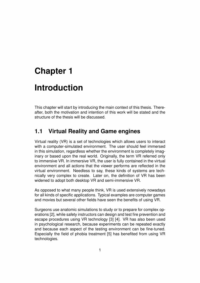
Virtual reality (VR) is a set of technologies which allows users to interactwith a computer-simulated environment. The user should feel immersedin this simulation, regardless whether the environment is completely imag-inary or based upon the real world. Originally, the term VR referred onlyto immersive VR. In immersive VR, the user is fully contained in the virtualenvironment and all actions that the viewer performs are reflected in thevirtual environment. Needless to say, these kinds of systems are tech-nically very complex to create. Later on, the definition of VR has beenwidened to adopt both desktop VR and semi-immersive VR.
As opposed to what many people think, VR is used extensively nowadaysfor all kinds of specific applications. Typical examples are computer gamesand movies but several other fields have seen the benefits of using VR.
Surgeons use anatomic simulations to study or to prepare for complex op-erations [2], while safety instructors can design and test fire prevention andescape procedures using VR technology [3] [4]. VR has also been usedin psychological research, because experiments can be repeated exactlyand because each aspect of the testing environment can be fine-tuned.Especially the field of phobia treatment [5] has benefited from using VRtechnologies.
1
As computers are becoming more powerful, VR can be realized on nor-mal desktop machines and even on mobile devices. During the last tenyears, game engines have been created in order to ease in the develop-ment and deployment of games. Today, these game engines have most ofthe features that are needed to develop VR-applications, except supportfor high-end interaction and display techniques. Thanks to this evolution,the Virtual World (VW), including its objects and their behaviors, can bevisualized and controlled by a game engine. This is the aim of the seriousgames initiatives. This is a term used to refer to a software application, de-veloped using game technology and game design principles for a primarypurpose other than pure entertainment. Examples of such purposes couldbe education, science, health care, etc. For this reason, in this thesis, theterm Virtual Environment (VE) application will be used. This can be a VR-application which is running on the desktop or even in the webbrowser, butit can also be a game. Both of them can be developed by using (existing)game engines.
The VE is made of a virtual world (VW), which contains a number of virtualobjects (VOs). These objects can have certain behaviors and can interactwith each other and with the user(s). Users can also navigate inside theVW and can interact with the VOs by means of input devices such as themouse and keyboard, joysticks or other devices.
2
1.2 Anatomy of a VE application
A VR application is composed of a number of key components. The fol-lowing is an enumeration of these components, according to [6]:
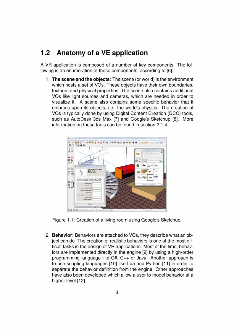
1. The scene and the objects: The scene (or world) is the environmentwhich hosts a set of VOs. These objects have their own boundaries,textures and physical properties. The scene also contains additionalVOs like light sources and cameras, which are needed in order tovisualize it. A scene also contains some specific behavior that itenforces upon its objects, i.e. the world’s physics. The creation ofVOs is typically done by using Digital Content Creation (DCC) tools,such as AutoDesk 3ds Max [7] and Google’s Sketchup [8]. Moreinformation on these tools can be found in section 2.1.4.
Figure 1.1: Creation of a living room using Google’s Sketchup.
2. Behavior: Behaviors are attached to VOs, they describe what an ob-ject can do. The creation of realistic behaviors is one of the most dif-ficult tasks in the design of VR applications. Most of the time, behav-iors are implemented directly in the engine [9] by using a high-orderprogramming language like C#, C++ or Java. Another approach isto use scripting languages [10] like Lua and Python [11] in order toseparate the behavior definition from the engine. Other approacheshave also been developed which allow a user to model behavior at ahigher level [12].
3
3. Interaction: Without allowing interaction, the user would find the Vir-tual World (VW) uninteresting. Users need to be able to navigatethrough the scene, manipulate and use the scene’s objects and re-ceive feedback from their actions. At the same time, objects them-selves need to interact with each other, for instance when two objectscollide, the physics engine needs to perform this collision in a realis-tic way. It is also possible that the objects themselves respond to acollision by exhibiting some behavior (ex. shrinking).
4. Sound: The use of sound in virtual environments greatly enhancesthe credibility of the scene. It is the task of the sound engineer to pro-vide realistic audio, given the state of the environment. To enhancethe illusion of immersion, the sound itself can also vary according tothe location of the user within the environment. For instance whenan avatar talks in a basement, an echo could be produced. Surroundsound techniques can be used to further enhance the credibility ofthe scene.
5. Communication: While the first VE applications were mainly offline,single-user systems, a lot of the contemporary solutions are beingused concurrently by a large set of users. As an example, considerSecond Life [13]. Tens of thousands of people are using the systemat the same time and want to communicate with each other. Thedeployment of such a large collaborative environment involves tack-ling classical network issues such as latency and synchronization butalso privacy and security problems.
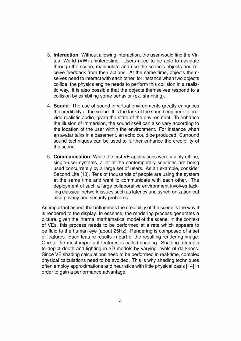
An important aspect that influences the credibility of the scene is the way itis rendered to the display. In essence, the rendering process generates apicture, given the internal mathematical model of the scene. In the contextof VEs, this process needs to be performed at a rate which appears tobe fluid to the human eye (about 25Hz). Rendering is composed of a setof features. Each feature results in part of the resulting rendering image.One of the most important features is called shading. Shading attemptsto depict depth and lighting in 3D models by varying levels of darkness.Since VE shading calculations need to be performed in real-time, complexphysical calculations need to be avoided. This is why shading techniquesoften employ approximations and heuristics with little physical basis [14] inorder to gain a performance advantage.
4
Figure 1.2: Common real-time shading algorithms: flat-, Gouraud- andPhong shading.
The creation of virtual environments and applications still remains acumbersome and time-consuming task. This is mainly because it relies onso many different fields, including graphic design, sound authoring, artifi-cial intelligence and of course software development. Luckily, the evolu-tions in both hard- and software have eased the creation of VE applica-tions.
Before any scene can be visualized, the geometry of the particularscene needs to be modeled. A lot of different Digital Content Creation(DCC) tools are available that allow modeling rich 3D models (see 2.1.4),ranging from freeware applications such as Google’s Sketchup [8], to high-end solutions like AutoDesk’s Maya [15] and 3ds Max [7]. However, noDCC tool is the silver bullet. Each product has its own set of features, fileformat exporters and interfacing style [9]. The chosen platform will restrictthe choice of compatible file formats and thereby also the set of appropri-ate tools. Luckily, most DCC tools provide a plugin mechanism that allowsthe addition of file formats. A large problem however is the quality of thedifferent exporters. Especially third-party exporters often do not work cor-rectly or do not export some features of the 3D model, such as embeddedbehaviors, annotations or parts of the model at all.
Many different platforms are available today (see 2.1) that take care ofthe visualization of 3D environments and expose an interface (API) that al-lows developers to control the virtual world. We will refer to these platformsas VE players. The choice of the VE player will impose some restrictions.For instance using Java3D [16] allows developers to target a large varietyof different operating systems, while using Microsoft XNA [17] allows thecreation of applications that run on the desktop, as well as the popularMicrosoft’s Xbox 360 console with a minimal amount of changes. Further-
5
more, several technologies are available which allow visualization of 3Denvironments inside webbrowsers. Examples of these are the eXtended3D (X3D) players (like Vivaty player [18]) and Google’s O3D framework(see 2.1). Therefore both designer and developers need to decide care-fully which platform will be used, keeping into account which audience isto be targeted. This is not so easy, because they should also grasp all theconstraints that are associated to the VE player.
1.3 Motivation
The motivation for the work presented in this thesis came from three mainobservations that were made at the beginning of the project and whichmostly relate to annotations. Annotating is the process of adding extra-information to a Virtual Object (VO) and its behaviors. We will now explainthese observations.
Observation 1: Annotations are only made for the static part of theVE and its VOs
Authoring tools are focusing mainly on the visual appearance of a VO andits behaviors. In recent years, these authoring tools have also been ex-tended with the possibility to add extra information about a VO through theuse of annotations, but this simple textual information is very basic and isonly about the static part of a VO, so not on its behaviors. Furthermore,these authoring tools are storing the limited additional information in thesame file which also contains the geometry of the VO (i.e. its visual ap-pearance) and its behaviors. This is not a good thing, because the sameVO could have different annotations attached to it, depending on the con-text it is in. For instance in the context of a video-game, a building could beannotated with text, stating that the enemies are inside this building. Butin the context of urban design, this same building could be annotated withthe text “IBM Office, no.9 Appleton Street, Boston”. To summarize: theappearance of a VO will remain constant, but the annotations can changedepending on the context. Based on this, a number of research groups(see chapter 2) have been working on improving this annotation processby allowing designers to attach different types of content to a VO, such astext, images over even media content. Nevertheless, VOs are dynamic innature, they can be interacted with and because they can have certain be-haviors attached to them. For this reason, these annotations should also
6
be about the behaviors and interactions. Most of the works on annotationshave focused on the static structure of a VE and its VOs.
Observation 2: Most of the VE players do not exploit the annotations.
Although part of a VO has been annotated during the design, the VE play-ers do not use these annotations, either to display to the end-users or toreason about these annotations in order to facilitate for instance the user’snavigation inside the VE. At this moment, these annotations still need tobe scripted or hard-coded. A good example is SecondLife (SL) [13] whichshows videos, images, text about a VO. These annotations are containedwith SL by means of a scripting language (the Linden Scripting Language[13]). This means that the designer needs to have some knowledge onprogramming. This may be one of the reasons why VEs still often lack interms of annotations as it is still too difficult for designer to use them.
Observation 3: Portability of VOs and their related behaviors acrossdifferent VE players is not well supported.
In the context of this work, the term portability will be used to indicate thata VO can be used on different VE players, while its visual representationand the behaviors that are attached to it remain the same. It is often thecase that a VO and its behaviors work perfectly on some VE players, butnot so well on others. As a result, the VO needs to be changed for differentVE players. As the authoring tools nowadays support different geometryfile formats, the static part of a VO can be generated in different formats.The problem of portability across multiple VE players can then be solved atleast for the static part of the VO. But behaviors are often related to someVOs and they are often VE player dependent. As a result behaviors mustbe completely reimplemented into different languages in order for them tobe supported by different VE players.
To overcome this problem of portability, it was thought that having astandard file format (like X3D [19] or COLLADA [20]) would overcomethese problems. But this is still not the case as the developers of VEplayers do not always follow the specification of these file formats. Asa consequence, behaviors often need to be reimplemented. For the de-signers of these VOs, this is really frustrating, because they often need tofigure out ways of making their VOs portable. This can take a lot of time.
7

Based on these three observations, the main motivation behind thiswork is to explore a new research direction for supporting and using theannotations on a VO in a more efficient way so that they can be used toprovide better feedback to end-users, resulting in higher user-satisfaction,but also to support portability across VE players.
8
1.4 Thesis aims and structure
1.4.1 Aims of this thesis
There are three main aims for this thesis:
1. Designing an approach which allows annotating the VOs of a VE withadditional information. This could be information regarding the objectin question or information about how the VO can be interacted with.
2. Developing a framework that uses these annotations so that VOs andtheir behaviors can be ported and used on VE players.
3. Based on our developed approach, an authoring tool will be devel-oped with the aims of allowing non VR-specialists to annotate VOsand their behaviors and which will provide all the necessary informa-tion so that our framework can use it in order to support portability.
We will attempt to provide a methodology which will lift VOs from theirpurely geometric function and into a more semantically rich role. Thislifting will promote the reuse and portability of these VOs on different VEplayers and in different VEs. VE players will have knowledge on the VOswhich they use. This knowledge can be communicated to the users of theVE, who will be able to know more about the VOs they encounter in the VE.As a result, users will be more interested in the VE, because it will havemore to offer them. Furthermore, we will explore a way in which VE playerscan exploit these additional semantics, so they will be able to perform thebehaviors that are associated to a VO. Suppose we are modeling a car.VOs today only consist of their geometry, so we cannot annotate this carwith the name of its manufacturer, its type, its reference manual, somereal-life pictures, etc. There is also no way in which we can annotate aVO, representing a car, with the abilities it can perform, like opening thedoors or trunk. Our approach will attempt to solve these two issues and willelaborate on a method which will allow the car and its associated abilitiesto be used on different VE players, without affecting the information that isavailable on the VO and the way the abilities of the car are executed by theVE player.
9
1.4.2 Thesis structure
Chapter 1 has introduced the context of this work as well as the motivationand aims of the thesis.Chapter 2 will provide some background information related to virtual real-ity and 3D computer graphics and will explain related work in the scope ofthis work.Chapter 3 will describe our approach: the “Smart Entity approach”.Chapter 4 will present the proposed framework and our Authoring Tool.Chapter 5 will provide a case study and will discuss the results and bene-fits of using our approach.Chapter 6 will elaborate on future workChapter 7 will discuss the conclusions of this thesis.
10
Chapter 2
Related work
This chapter will start by providing some background regarding 3D com-puter graphics and VR in general. This section can be skipped by readerswho are already familiar with VR. Later on, related work in the scope ofthis thesis will be reviewed.
2.1 Background
The development of computer graphics is a hard task which relies on awide set of different fields, including graphic design, mathematics, physics,etc. In this section, some important concepts which have been used in thiswork will be briefly introduced. A more elaborate overview of computergraphics can be found in [14].
2.1.1 Virtual Environments
Techniques
Several techniques are available in order to visualize computed 3D simu-lations. A simple display can be used to show the simulation, this is calledDesktop VR, but these displays cannot represent depth differences in arealistic and believable way. A number of companies, such as Philips [21]and Mitsubishi [22] are working on a flat display that can create a threedimensional illusion. Mitsubishi states that the next revolution of televisionis 3D TV. This surely seems to be a credible statement and the first resultslook positive, but it is not known when 3D TV will be available to the con-sumer’s market.
11
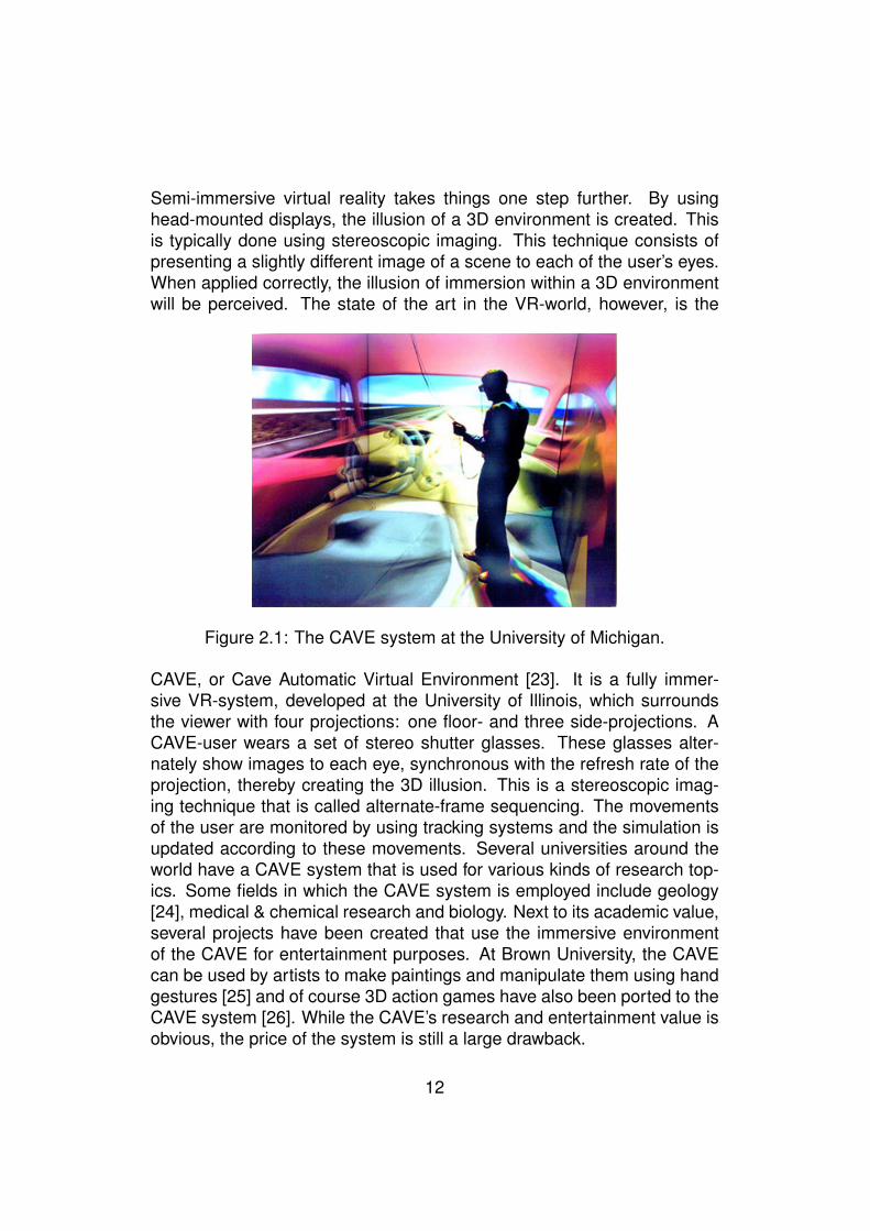
Semi-immersive virtual reality takes things one step further. By usinghead-mounted displays, the illusion of a 3D environment is created. Thisis typically done using stereoscopic imaging. This technique consists ofpresenting a slightly different image of a scene to each of the user’s eyes.When applied correctly, the illusion of immersion within a 3D environmentwill be perceived. The state of the art in the VR-world, however, is the
Figure 2.1: The CAVE system at the University of Michigan.
CAVE, or Cave Automatic Virtual Environment [23]. It is a fully immer-sive VR-system, developed at the University of Illinois, which surroundsthe viewer with four projections: one floor- and three side-projections. ACAVE-user wears a set of stereo shutter glasses. These glasses alter-nately show images to each eye, synchronous with the refresh rate of theprojection, thereby creating the 3D illusion. This is a stereoscopic imag-ing technique that is called alternate-frame sequencing. The movementsof the user are monitored by using tracking systems and the simulation isupdated according to these movements. Several universities around theworld have a CAVE system that is used for various kinds of research top-ics. Some fields in which the CAVE system is employed include geology[24], medical & chemical research and biology. Next to its academic value,several projects have been created that use the immersive environmentof the CAVE for entertainment purposes. At Brown University, the CAVEcan be used by artists to make paintings and manipulate them using handgestures [25] and of course 3D action games have also been ported to theCAVE system [26]. While the CAVE’s research and entertainment value isobvious, the price of the system is still a large drawback.
12
Mixed reality
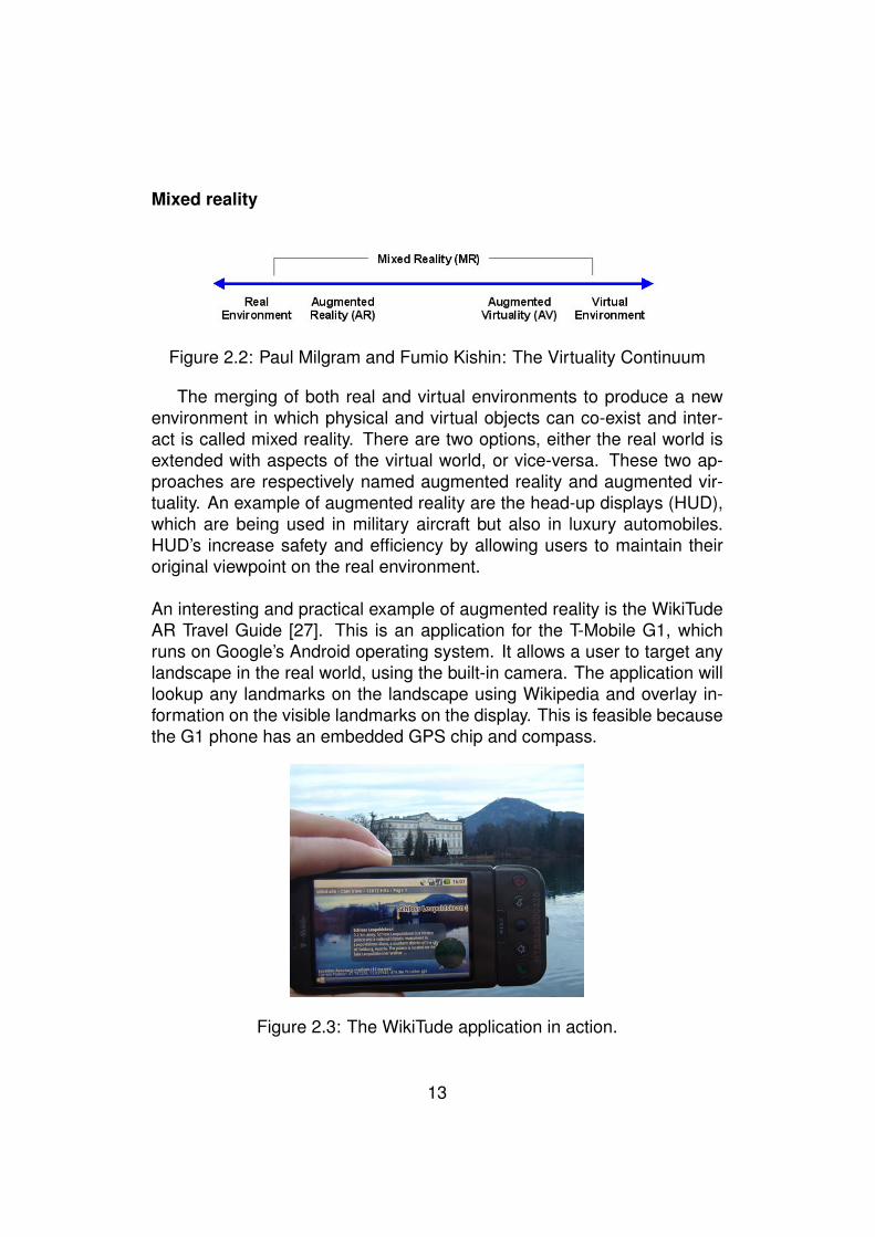
Figure 2.2: Paul Milgram and Fumio Kishin: The Virtuality Continuum
The merging of both real and virtual environments to produce a newenvironment in which physical and virtual objects can co-exist and inter-act is called mixed reality. There are two options, either the real world isextended with aspects of the virtual world, or vice-versa. These two ap-proaches are respectively named augmented reality and augmented vir-tuality. An example of augmented reality are the head-up displays (HUD),which are being used in military aircraft but also in luxury automobiles.HUD’s increase safety and efficiency by allowing users to maintain theiroriginal viewpoint on the real environment.
An interesting and practical example of augmented reality is the WikiTudeAR Travel Guide [27]. This is an application for the T-Mobile G1, whichruns on Google’s Android operating system. It allows a user to target anylandscape in the real world, using the built-in camera. The application willlookup any landmarks on the landscape using Wikipedia and overlay in-formation on the visible landmarks on the display. This is feasible becausethe G1 phone has an embedded GPS chip and compass.
Figure 2.3: The WikiTude application in action.
13
2.1.2 3D Computer Graphics
The scene graph
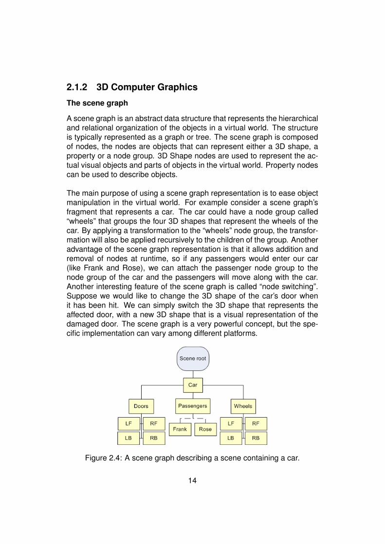
A scene graph is an abstract data structure that represents the hierarchicaland relational organization of the objects in a virtual world. The structureis typically represented as a graph or tree. The scene graph is composedof nodes, the nodes are objects that can represent either a 3D shape, aproperty or a node group. 3D Shape nodes are used to represent the ac-tual visual objects and parts of objects in the virtual world. Property nodescan be used to describe objects.
The main purpose of using a scene graph representation is to ease objectmanipulation in the virtual world. For example consider a scene graph’sfragment that represents a car. The car could have a node group called“wheels” that groups the four 3D shapes that represent the wheels of thecar. By applying a transformation to the “wheels” node group, the transfor-mation will also be applied recursively to the children of the group. Anotheradvantage of the scene graph representation is that it allows addition andremoval of nodes at runtime, so if any passengers would enter our car(like Frank and Rose), we can attach the passenger node group to thenode group of the car and the passengers will move along with the car.Another interesting feature of the scene graph is called “node switching”.Suppose we would like to change the 3D shape of the car’s door whenit has been hit. We can simply switch the 3D shape that represents theaffected door, with a new 3D shape that is a visual representation of thedamaged door. The scene graph is a very powerful concept, but the spe-cific implementation can vary among different platforms.
Figure 2.4: A scene graph describing a scene containing a car.
14
The camera system
A camera is essential to any virtual environments. Obviously, some sort ofviewpoint to the world has to be specified before anything can be seen inthat world. To define a simple camera in a 3D virtual world, we first needthe following properties of the camera:
1. Position: A vector that defines where the camera is positioned in theworld.
2. Target: A vector that defines which point the camera should be fac-ing, the position and target vectors define the viewing direction of thecamera.
3. Up direction: A normalized vector that defines which direction isup for the particular camera. Suppose we are looking at a chair inthe real world, with only the position and target vectors known, wecould still rotate our heads along the viewing direction, which resultsin many possible camera poses. In a typical virtual environment, theup direction would be (0, 1, 0).
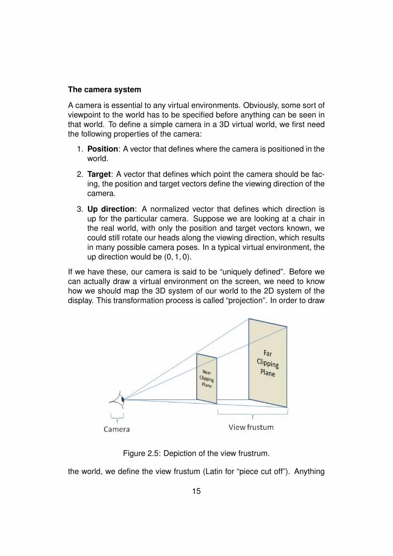
If we have these, our camera is said to be “uniquely defined”. Before wecan actually draw a virtual environment on the screen, we need to knowhow we should map the 3D system of our world to the 2D system of thedisplay. This transformation process is called “projection”. In order to draw
Figure 2.5: Depiction of the view frustrum.
the world, we define the view frustum (Latin for “piece cut off”). Anything
15
that is within the frustum will be drawn by the engine, everything else will beclipped to increase performance (frustum culling). That is, anything furtherthan the near clipping plane and closer than the far clipping plane. Theseplanes are perpendicular to the camera’s direction. The use of these clip-ping planes can result in reduced realism, because the viewer may noticethat everything further than the far clipping plane disappears or is only dis-played partially. The addition of fog can help soften this transition. Thedistance of the near and far clipping planes depends on the purpose of theVE.
Transformations
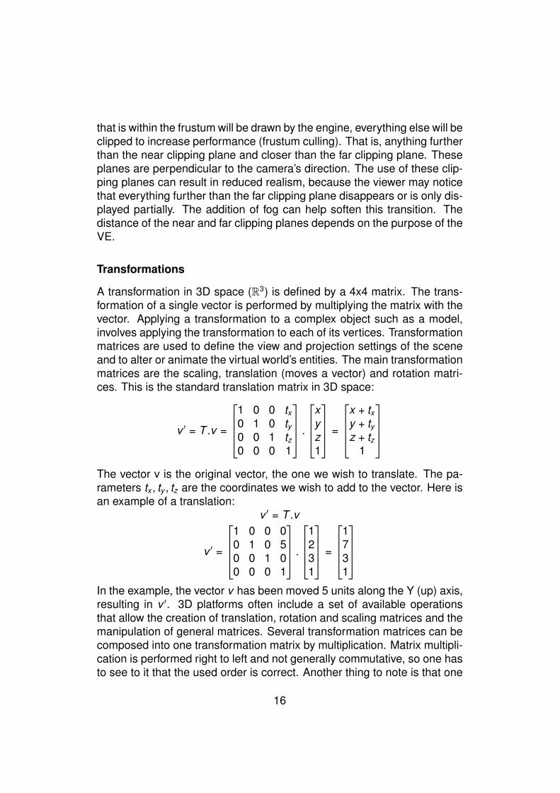
A transformation in 3D space (R3) is defined by a 4x4 matrix. The trans-formation of a single vector is performed by multiplying the matrix with thevector. Applying a transformation to a complex object such as a model,involves applying the transformation to each of its vertices. Transformationmatrices are used to define the view and projection settings of the sceneand to alter or animate the virtual world’s entities. The main transformationmatrices are the scaling, translation (moves a vector) and rotation matri-ces. This is the standard translation matrix in 3D space:
v ′ = T .v =
1 0 0 tx0 1 0 ty0 0 1 tz0 0 0 1
.
xyz1
=
x + txy + tyz + tz
1
The vector v is the original vector, the one we wish to translate. The pa-rameters tx , ty , tz are the coordinates we wish to add to the vector. Here isan example of a translation:
v ′ = T .v
v ′ =
1 0 0 00 1 0 50 0 1 00 0 0 1
.
1231
=
1731
In the example, the vector v has been moved 5 units along the Y (up) axis,resulting in v ′. 3D platforms often include a set of available operationsthat allow the creation of translation, rotation and scaling matrices and themanipulation of general matrices. Several transformation matrices can becomposed into one transformation matrix by multiplication. Matrix multipli-cation is performed right to left and not generally commutative, so one hasto see to it that the used order is correct. Another thing to note is that one
16
transformation may influence another transformation. For instance whentwo rotations around different axes are being combined, the axes of thesecond rotation will have been rotated by the first rotation. This is called“Gimbal lock”. A property of rotations is that two rotations can alwaysbe combined into one single rotation. Furthermore, any rotation can berepresented by an axis (normalized 3D vector) and an angle of revolutionaround that axis. To store these two properties, a quaternion is typicallyused. A quaternion is an extension to the complex number system. Theset of quaternions, H, is equal to R4, a four dimensional vector space overthe real numbers. The first three components represent the x-, y- and z-components of a vector in R3, these define the rotation axis. The fourthcomponent (referred to as w), denotes the angle of the rotation. Three op-erations are defined on H: Addition, scalar multiplication and quaternionmultiplication.
H = {(x , y , z, w)|x , y , z, w ∈ R}
q = xi + yj + zk + w (q ∈ H)
Since quaternions are so heavily used in the field of 3D graphics to rep-resent a rotation around an arbitrary axis, several platforms expose a setof functions that allow users to handle quaternions without having to knowthe full mathematical extent of the topic. For example, both Java and XNAhave classes (Quat4d , Quaternion) which have methods that performquaternion operations and allow instantiation using the four componentswhich were discussed above.
17
Coordinate system
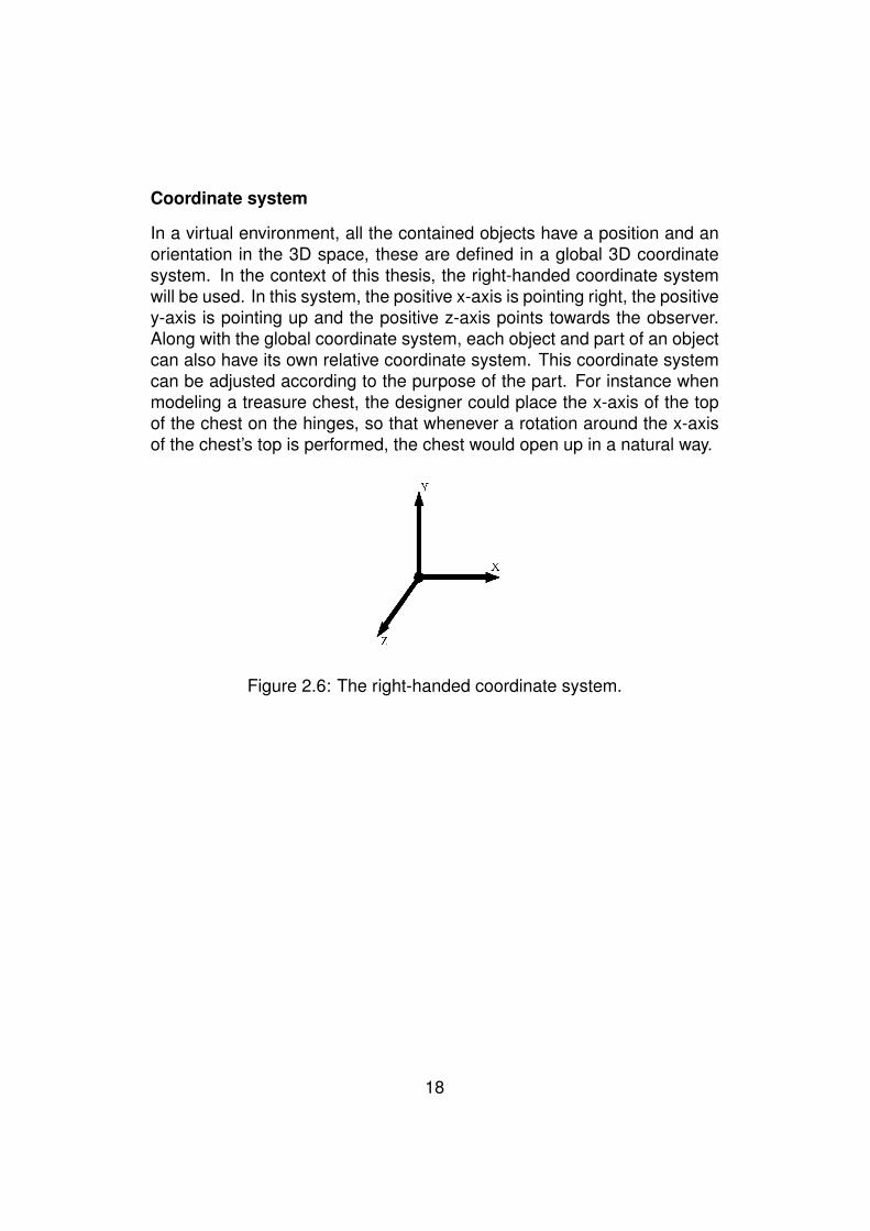
In a virtual environment, all the contained objects have a position and anorientation in the 3D space, these are defined in a global 3D coordinatesystem. In the context of this thesis, the right-handed coordinate systemwill be used. In this system, the positive x-axis is pointing right, the positivey-axis is pointing up and the positive z-axis points towards the observer.Along with the global coordinate system, each object and part of an objectcan also have its own relative coordinate system. This coordinate systemcan be adjusted according to the purpose of the part. For instance whenmodeling a treasure chest, the designer could place the x-axis of the topof the chest on the hinges, so that whenever a rotation around the x-axisof the chest’s top is performed, the chest would open up in a natural way.
Figure 2.6: The right-handed coordinate system.
18
2.1.3 3D Model file formats
The creation and management of 3D virtual environments is overwhelmedby tools and file formats. Hundreds of different file formats are used, eachwith its ups and downs and dozens of high (and low) quality 3D authoringtools are available to content creators. In this section, some of the mostrelevant file formats that are available and used today are discussed.
X3D
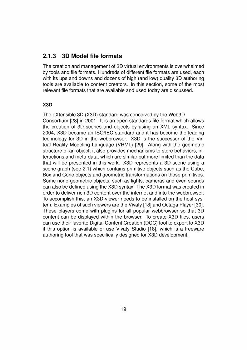
The eXtensible 3D (X3D) standard was conceived by the Web3DConsortium [28] in 2001. It is an open standards file format which allowsthe creation of 3D scenes and objects by using an XML syntax. Since2004, X3D became an ISO/IEC standard and it has become the leadingtechnology for 3D in the webbrowser. X3D is the successor of the Vir-tual Reality Modeling Language (VRML) [29]. Along with the geometricstructure of an object, it also provides mechanisms to store behaviors, in-teractions and meta-data, which are similar but more limited than the datathat will be presented in this work. X3D represents a 3D scene using ascene graph (see 2.1) which contains primitive objects such as the Cube,Box and Cone objects and geometric transformations on those primitives.Some none-geometric objects, such as lights, cameras and even soundscan also be defined using the X3D syntax. The X3D format was created inorder to deliver rich 3D content over the internet and into the webbrowser.To accomplish this, an X3D-viewer needs to be installed on the host sys-tem. Examples of such viewers are the Vivaty [18] and Octaga Player [30].These players come with plugins for all popular webbrowser so that 3Dcontent can be displayed within the browser. To create X3D files, userscan use their favorite Digital Content Creation (DCC) tool to export to X3Dif this option is available or use Vivaty Studio [18], which is a freewareauthoring tool that was specifically designed for X3D development.
19
COLLADA
COLLADA is an attempt for establishing an interchange file format for in-teractive virtual environments. COLLADA is defined in an XML Schemeand was developed as a reaction to the various incompatible file formatsthat are around today. It was originally conceived by Sony Computer En-tertainment in October 2004 to be the official format for the PlayStation 3and PlayStation Portable game consoles. During its development, severalother companies saw benefit in COLLADA and joined in, resulting in theKronos Group consortium [20]. Members of this consortium are some ofthe biggest names in the (3D) entertainment sector, such as Blizzard, Dell,Sony, Barco, Creative, Electronic Arts, Google and many more. The COL-LADA format was originally intended to be an intermediate format, to beused for transporting data from one digital content creation tool (DCC) tothe other (ex.: 3D Studio Max to Blender) but some applications have usedCOLLADA as their native file format for storing 3D geometry. An exampleof this is Google Earth, which allows users to populate a map with a 3Dobject, using the COLLADA standard.
A standard such as COLLADA is a good thing for the digital entertain-ment industry, because it enhances interoperability between different plat-forms and because it can serve as the de facto standard for representing3D objects. Support for COLLADA is available in almost any authoringtool, either native or using a plugin, but support in 3D API’s is limited andmostly unofficial. Both Java3D and XNA have an unofficial COLLADA im-porter but these are far from production-ready and could not be used forthe proof of concept. Hopefully COLLADA will evolve further and gain evenwider acceptance in the future.
20
2.1.4 Digital Content Creation
Many different applications have been developed in order to ease the de-sign of 3D models and animations. Each with its own ups and downs.Choosing the right tool for the trade is essential in order to increase pro-ductivity, especially for beginning 3D designers. In this section, some ofthe DCC tool’s that have been used will be discussed briefly.
Sketchup
Google’s Sketchup [8] is an award winning 3D modeling application thatwas developed by @Last Software. In March 2006, Google acquired thiscompany and continued development of the application. The main advan-tage of using Sketchup is the low learning curve. Indeed, Sketchup boastsan amazingly simple, yet powerful click-and-drag user interface that haseven been patented by Google. Best of all, Sketchup is completely freeand available for download. There is also a professional edition whichsupports additional file formats and editing features. This version is re-quired if the software is used for commercial purposes. Google Sketchupenables any user to publish 3D models to Google Earth or to a communityrepository called the Google Warehouse. This repository allows anyoneto search for VOs, allowing even the layman to create rich virtual scenes.The application’s professional version also allows exporting 3D models toa large set of different formats, including 3DS, OBJ, DAE (COLLADA) andFBX [31]. Sketchup does not supply any animation support by default.
21
Blender
Blender [32] is a 3D modeling application that has been released as freesoftware under the GNU General Public License (GPL). Though it is cost-less, it offers a plethora of professional features to the user that are other-wise only available in high-end software. Blender is available for almost allpopular platforms and boasts a large community of users. As oppose toSketchup, Blender has a really steep learning curve. The use of keyboardshortcuts is almost imperative to working with Blender but once these key-board shortcuts have been mastered, modeling with Blender can be muchfaster than with other commercial solutions. Blender offers export fea-tures to a lot of different formats, including 3DS, OBJ, DAE (COLLADA)and many more. Along with the creation of static models, Blender allowsuser to create rich (physics) animations, involving skeletons and inversekinematics and even games.
3ds Max
For some time now, AutoDesk’s 3Ds Max [7] (formerly known as 3D Stu-dio Max) has been the de facto standard in the 3D modeling world. Theapplication has a wide range of features, which seem overwhelming inthe beginning but many game-content creators have sworn by it. Luck-ily a lot of free study material is available on the internet in order to helpnew users. AutoDesk features one of the widest sets of exporters that areavailable today, including 3DS, OBJ, DAE, X and FBX. Since the FBX for-mat was created by AutoDesk [31], 3Ds Max’s FBX exporter is the bestavailable on any DCC tool. This makes the application an ideal DCC toolfor the XNA platform. Its user interface is also a revelation as oppose toBlender, though some functionality is well hidden. It is also possible tocreate animations using 3ds Max, but its sister-product AutoDesk’s Mayais especially created for that purpose.
22

2.1.5 VE players
Several VE players are available for developing and visualizing 3D virtualenvironments. In this section, a brief overview of the most used VE play-ers will be given, along with some considerations with regards to ease ofdevelopment, speed and presentation.
Java3D
Java3D [16] is an open-source, low-level 3D API that was created by Intel,Silicon Graphics, Apple and Sun Microsystems. It is not part of the JavaDeveloper Kit (JDK). Java3D is an abstraction layer that can run on top ofOpenGL or Direct3D and in the Java spirit, it is also platform-independent(though not for mobile devices). An interesting feature is the ability tocreate Java3D-applets. As all the other platforms, it supplies high-levelmethods for creating and manipulating the 3D geometry (using a scenegraph representation). Any Java IDE can be used to develop Java3D ap-plications, the only thing that needs to be done is adding the Java3D jarfile to the classpath. Importers are available for different formats, includ-ing 3DS, OBJ, X3D and VRML [29]. Unfortunately DirectX, FBX or theindustry standard COLLADA (DAE) file format support is unavailable. InJanuary 2008, Sun announced that improvements to Java3D would be puton hold to focus efforts on integrating support with JavaFX to complementJavaFX’s 2D scene graph. Nevertheless, Java3D is being used a lot to-day, though not that much information on it is available on the web (ascompared to Microsoft XNA [17]).
23
Adobe Flash-based platforms
Since both the availability of broadband and the power of graphics cardshave been increased during the last couple of years, the browser hasbecome an ideal platform for the delivery of rich VR applications to themasses. Since Adobe Flash is one of the standards for creating Rich In-ternet Applications (99% of the web’s users have Adobe’s Flash player[33]), several third party attempts have been made to extend this platformwith easy to use 3D capabilities:
• Papervision3D [34]: Papervision3D is the preferred engine for nowbecause of its large userbase. Papervision3D delivers 3D virtual en-vironments to every webbrowser with Flash support and has supportfor COLLADA files (including animations). Both of these featuresmake Paperversion3D very attractive for web-based virtual environ-ments.
• Alternativa3D [35]: A very impressive and performant Flash-basedengine that is free for non-commercial use is Alternativa3D. It excelsin the visualization of large, navigatable, environments and is alreadycompatible with Adobe Flash 10. Alternativa3D can import 3DS andOBJ files, unfortunately COLLADA support is not yet available.
Since Adobe Flash 9 has no support for hardware acceleration, all of thegraphics calculations of these engines are performed on the CPU. Flash10 however will support hardware acceleration. Being able to use the fullpower the Graphics Processing Unit (GPU) will result in large speed ben-efits. One large drawback however remains that all assets (textures, mod-els, sound, ...) still need to be downloaded from a webserver, resulting inlonger loading times.
24
Google’s O3D
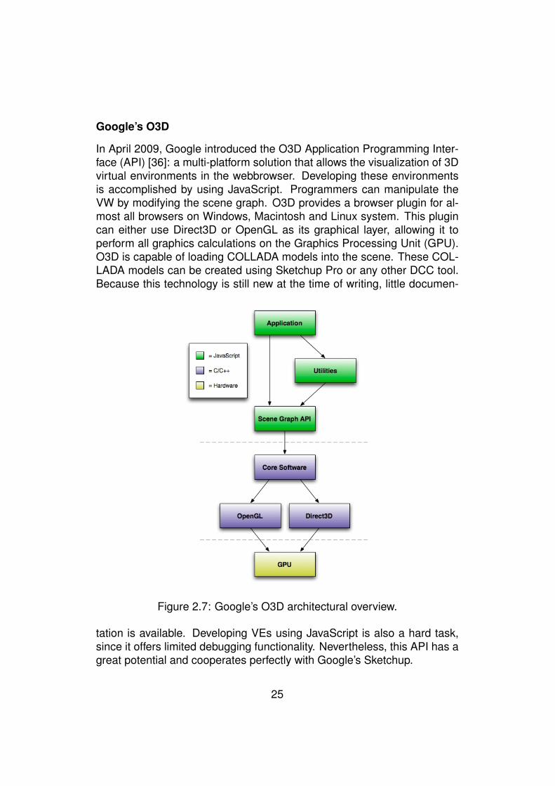
In April 2009, Google introduced the O3D Application Programming Inter-face (API) [36]: a multi-platform solution that allows the visualization of 3Dvirtual environments in the webbrowser. Developing these environmentsis accomplished by using JavaScript. Programmers can manipulate theVW by modifying the scene graph. O3D provides a browser plugin for al-most all browsers on Windows, Macintosh and Linux system. This plugincan either use Direct3D or OpenGL as its graphical layer, allowing it toperform all graphics calculations on the Graphics Processing Unit (GPU).O3D is capable of loading COLLADA models into the scene. These COL-LADA models can be created using Sketchup Pro or any other DCC tool.Because this technology is still new at the time of writing, little documen-
Figure 2.7: Google’s O3D architectural overview.
tation is available. Developing VEs using JavaScript is also a hard task,since it offers limited debugging functionality. Nevertheless, this API has agreat potential and cooperates perfectly with Google’s Sketchup.
25
Microsoft XNA
Microsoft’s XNA [17] (XNA is not an acronym) was released in December2006. The main intent of the framework was to provide easy, yet power-ful features to game developers. The framework is based on the Microsoft.NET framework and runs in a so called “managed execution environment”.This means that the source code is first compiled to an intermediate codeformat (called managed code, comparable to Java’s bytecode), this codeis executed by a virtual machine. Execution environments are availablefor all popular Microsoft Windows versions and for the Xbox 360 gamingconsole. This allows developers to create games for the desktop computerand later on port them to the Xbox 360 console with little extra effort.
The XNA framework allows developers to have fine-grained control over allaspects of a game. HLSL (High Level Shading Language) effects can beused to program the graphics card’s pixel, vertex and geometry shaders.Using HLSL, developers can add custom post-processing effects such asblurs, color effects, etc. but also complex lighting effects such as Gouraudand Phong shading. The power of XNA can be overwhelming to begin-ners. Fortunately there is a lot of documentation [37] available, there iscommunity support [38] and a lot of great books [39] [40] have been pub-lished. The framework also integrates seamlessly into Microsoft VisualStudio, thereby enabling code completion, debugging and refactoring fea-tures. The 3D model formats that can be used are FBX [31] (AutoDesk)and X (Microsoft DirectX), unfortunately, only limited COLLADA supportwas available at the time of writing. Custom content format importers canbe added by extending the Content Pipeline [41]. The Content Pipeline isresponsible for reading data from the filesystem, parsing it and loading itinto an XNA specific format such as the Model or Texture2D classes, so itcan be used by the application.
26
2.2 Related research
Several papers have investigated means of adding semantics to virtualenvironments as a whole. In [42], the authors present means of creatingPoints of Interest (POIs) in an environment. These POIs can be asso-ciated with different kinds of content, including text, videos and images.This approach was developed in order to annotate the environments andthe elements within this environment. The annotations are not bound tothe objects but to the context of the object within a scene. The notion ofSmart Objects has been used in [43], [44], [45] and [46] to denote objectswhich contain information on how they can be interacted with and manip-ulated. This information can be parts of the object which can be graspedand can define how an avatar should be animated while interacting withthe object. In this work, some of the advantages of these added semanticsare presented: by separating the animation specific information from theenvironment, the same model can be used in multiple applications. Fur-thermore, this notion of attached semantics promotes an object-orienteddesign, since each object encapsulates its own attributes and operations.
While in [43] and [44], the main purpose of the attached semantics is forobject manipulation purposes, this thesis will focus on attaching semanticswhich describe the entity itself in more detail and which serve as a meansof communication to the visitor of the Virtual Environment, hence SmartEntities. In [47], it is recognized that it is difficult to define a closed andsufficient set of behaviors, therefore our approach suggests a techniquewhich allows the addition of new behaviors and even the modification ofexisting ones.
In [48], a framework is presented which focuses on the creation of rich be-haviors by using both a graphical and a textual modeling language. Thesebehaviors are instantiated by adjusting their parameters. This parameter-ization is also used in the presented approach. In this thesis, techniqueswill be presented which allow the attachment of parameterized behaviorsto an entity and which allow the invocation of these behaviors on differ-ent VE players. In order to describe the semantics of our Smart Entities,the definition of Smart Objects in [47] has been used as a reference. Thedescriptions feature has been extended to include typing and visibility in-formation and the focus is more on describing an entity’s abilities and be-havior rather than on actor-object interaction.
27
Chapter 3
The Smart Entity approach
This chapter will first review some important points which will explain theapproach that was taken in this thesis. Thereafter, this approach will beelaborated further.
Note that in the context of this work, the term behavior refers to behaviorsof levels zero, one and two in the behavior hierarchy which was proposedin [49]. Level zero relates to the direct modification of an entity’s attributessuch as its location, size and color. Level one behaviors define the modifi-cations of level zero over time, resulting in animations. Level two behaviorsare sequential calls to level one behaviors. The third and top-level behav-iors are not in the scope of this thesis, as they involve high-level decisionmaking techniques such as deducing what a VO should do at a particulartime.
3.1 Overview of the approach
As discussed in chapter 1, there are three main aims of the presented ap-proach. First, the approach should provide a way to express informationabout a VO and should allow VE players to take advantage of this addi-tional information. Second, the approach should define a framework thatfacilitates portability of VOs and their behaviors by using this added infor-mation. Third, an Authoring Tool will be developed which conforms to ourapproach and enables designers to annotate VOs.
The Smart Entity approach is made up of two important elements. Thefirst element is a file format which captures all kinds of information relatedto the VO through annotations. The need for this new file format originates
28

from the observation that all DCC tools store the geometric definition andthe behaviors related to VOs in a single file, but often in different formats(FBX [31], COLLADA [20], X3D [19], etc.). Furthermore, the formats thatare used are often chosen in function of the VE player. Note that DCCtools which support annotations in a limited way, also store this informa-tion inside the file itself. They also store the behaviors that have beencreated by a designer in that same file. To summarize: the geometry ofa VO and some limited semantics and behaviors are all bundled into onefile. Another observation is that many VE players, which parse these files,were often developed before these file formats have been extended withthe possibility to store these annotations. Therefore this information is al-most never processed by the VE player. This is one of the reasons whyVEs are still poor in terms of extra information other than information aboutthe geometry of a VO, its visual appearance and its behaviors.
Storing these annotations within the same file as the visual representa-tion and behaviors of a VO provides another disadvantage. The creationand maintenance of such VOs is not easy and needs to be done by ex-perts that know their DCC tools well. Furthermore, the visual appearanceof an object may not change often, but the annotations that are attachedto it may change depending on the context the VO is in or even dependingon the background of the end-user (culture, language, education, etc.).
Based on this, we have developed an approach which specifies a new fileformat which will facilitate the updates of this additional information and theportability of the VO and its information on different VE players. In otherwords, the VOs, which until now were only visual in nature, have been ex-tended with relevant additional information. These VOs will be referred toas entities. The annotations will later on also be used to achieve portabil-ity of the VO and its associated behaviors across different VE players. Theannotations will also be used to provide rich information about the VO tothe user. By providing this information to users, they will be more attractedto the VE, since it has more information to offer them.
Users will also be able to know what the abilities of a VO are. By abil-ities, we mean that once a behavior is attached to a VO, the VO will havean ability to do something. For instance, suppose that a VO representinga door has two behaviors attached to it: opening and closing. We canthen say that the VO has the ability to open and close the door. Further-more, the behaviors can annotated so that the VE player will know howto invoke the abilities associated to that VO. This will also provide the ad-vantage that VOs and VE users can know how to interact with each other.
29
For instance, the user represented by a human avatar, has clicked a doorin a VE. The VE player can then lookup which abilities the door can per-form and show a menu to the user, stating that the door can be opened orclosed. This is the reason why we have extended the word entity with theadjective smart. As a result, VEs will become richer and they can becomemore useful and entertaining to their users because of the feedback userswill receive. This may be a motivation towards developers of VE playersto support this proposed format. Therefore, the second element in our ap-proach is a framework that makes the assumption that existing VE playershave been extended to support the proposed format and it will show howthe promoted portability becomes feasible.
30
3.2 Smart Entity file format
As explained, our Smart Entity file format will contain information throughthe use of annotations about the VO and its behaviors. The informationwill be stated from both the users’ point of view and from the VE player’sperspective. Because our file format should be platform-independent, wehave chosen an XML syntax to express its data. Most platforms haveparsers that are more than capable of parsing our file format. The structureof the file format which has been formally captured by means of an XMLSchema (XSD) file. This XSD file can be found in the appendix (8.1). Topresent an overview of the information that is contained into the format, thedata model of the Smart Entity file format is displayed in figure 3.1. Eachof the components in the data model will be described in more details now.
31
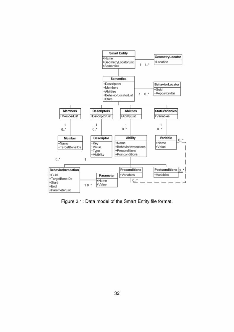
Figure 3.1: Data model of the Smart Entity file format.
32

3.2.1 Geometry LocatorsSince the Smart Entity file relates to a 3D model, one of the first things thatare required is a link to such a 3D model in some specified 3D model for-mat. Because different VE players often also use different model formats,only linking to one model format may not suffice and may break down theinteroperability we are looking for. For instance if platform A uses Au-todesk’s FBX format [31] as its format while platform B uses COLLADA[20] and our Smart Entity file only links to an FBX model, then the SmartEntity could only be used by platform A. This is why the presented formatprovides the possibility to link to multiple model files, by providing multipleURIs to the same 3D model, but in different formats. Designers can eas-ily store the same model in different formats using the DCC tool of theirchoice, either by default or by using a plugin. This approach allows for awider platform support of the created definitions. It is the task of the En-gine Extension (see 3.3) to check which geometry locators are availableand to pick a model format which is compatible with the specific platform.To summarize: our approach allows attaching the same 3D model in differ-ent formats so that the VE player can decide which 3D model it will load.These geometry locators are expressed in the XML file format based onthe XSD schema (see 8.1) as follows:
<GeometryLocators><GeometryLocator location="http://www.nokia.be/3d/nokia.X" /><GeometryLocator location="http://www.nokia.be/3d/nokia.X3D" /><GeometryLocator location="http://www.nokia.be/3d/nokia.DAE" />
</GeometryLocators>
Note that this example shows only a part of the Smart Entity file format.The VE player which parses the Smart Entity file format can choose which3D model it will load, depending on the format of the 3D model. In the XMLsnippet, three URIs are available that point to a location on the network.This means that a VE player needs to download a compatible model first.Using URIs, we can also link to files on the local file system by using the“file://” prefix.
33

3.2.2 Descriptors
A good way of describing properties of a VO would be by using a key/valuemechanism. For each VO, we can store a set of key/values that describeits properties from the VE users’ perspective. Some examples are: (name,“Dominique”), (age, “23”), (gender, “male”). A key/value pair that describesa VO will be referred to as a descriptor. These descriptors are mainlyintended to be shown to users of the VE but could also be used by theVE player itself. As an example of the use of these descriptors, considerthe following scenario: an avatar, controlled by a user, walks around in avirtual museum. The user can click any painting in the environment anda menu will pop up that gives a brief summary of the selected work. Theinformation shown is originated from the descriptors in a Smart Entity file,which links to the 3D model of the painting. The main usage of descriptorsis to serve as a means of communication between the VO and a user, butthey could also be used by the VE player internally. This indicates thatthere is a grouping that is needed. Some descriptors are to be exposed tousers while others are to be consulted only by the VE player. This requiresus to attach a visibility to a descriptor. Two types of visibility are needed:
• Public: A public descriptor is intended to serve as a communicationto the users of the VE. They state relevant properties of the entity,such as a painting’s artist(s) and style.
• Private: Private descriptors are to be used by the VE application.Examples are the entity’s meta-data such as the author and the usedDCC tool. Other examples could be points-of-interest (POIs) of theentity, like the location of a door’s hinge.
From the examples that were stated above, we can deduce that simpletext-based key/values are not enough. The values of properties should betyped, because the information they contain can be anything. It could beprimitive content such as text, numbers or vector, but it can also containlinks to resources (URIs), such as images, audio, video or documents.In order to give the VE application an idea of what content it can expectand to make the content machine-processable, some typing information isneeded for each descriptor. Furthermore, it is necessary to agree on a setof common data types that are to be used.
34
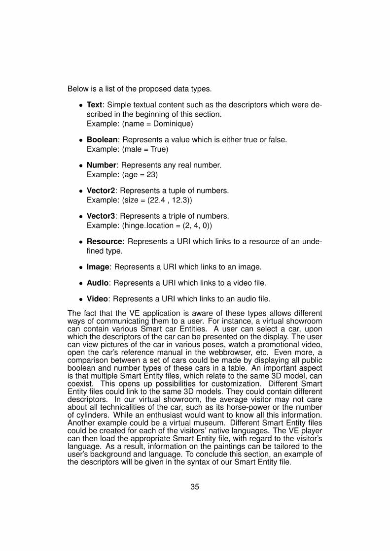
Below is a list of the proposed data types.
• Text: Simple textual content such as the descriptors which were de-scribed in the beginning of this section.Example: (name = Dominique)
• Boolean: Represents a value which is either true or false.Example: (male = True)
• Number: Represents any real number.Example: (age = 23)
• Vector2: Represents a tuple of numbers.Example: (size = (22.4 , 12.3))
• Vector3: Represents a triple of numbers.Example: (hinge location = (2, 4, 0))
• Resource: Represents a URI which links to a resource of an unde-fined type.
• Image: Represents a URI which links to an image.
• Audio: Represents a URI which links to a video file.
• Video: Represents a URI which links to an audio file.
The fact that the VE application is aware of these types allows differentways of communicating them to a user. For instance, a virtual showroomcan contain various Smart car Entities. A user can select a car, uponwhich the descriptors of the car can be presented on the display. The usercan view pictures of the car in various poses, watch a promotional video,open the car’s reference manual in the webbrowser, etc. Even more, acomparison between a set of cars could be made by displaying all publicboolean and number types of these cars in a table. An important aspectis that multiple Smart Entity files, which relate to the same 3D model, cancoexist. This opens up possibilities for customization. Different SmartEntity files could link to the same 3D models. They could contain differentdescriptors. In our virtual showroom, the average visitor may not careabout all technicalities of the car, such as its horse-power or the numberof cylinders. While an enthusiast would want to know all this information.Another example could be a virtual museum. Different Smart Entity filescould be created for each of the visitors’ native languages. The VE playercan then load the appropriate Smart Entity file, with regard to the visitor’slanguage. As a result, information on the paintings can be tailored to theuser’s background and language. To conclude this section, an example ofthe descriptors will be given in the syntax of our Smart Entity file.
35
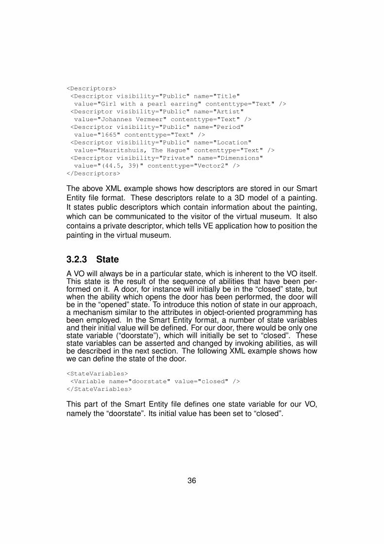
<Descriptors><Descriptor visibility="Public" name="Title"value="Girl with a pearl earring" contenttype="Text" /><Descriptor visibility="Public" name="Artist"value="Johannes Vermeer" contenttype="Text" /><Descriptor visibility="Public" name="Period"value="1665" contenttype="Text" /><Descriptor visibility="Public" name="Location"value="Mauritshuis, The Hague" contenttype="Text" /><Descriptor visibility="Private" name="Dimensions"value="(44.5, 39)" contenttype="Vector2" />
</Descriptors>
The above XML example shows how descriptors are stored in our SmartEntity file format. These descriptors relate to a 3D model of a painting.It states public descriptors which contain information about the painting,which can be communicated to the visitor of the virtual museum. It alsocontains a private descriptor, which tells VE application how to position thepainting in the virtual museum.
3.2.3 StateA VO will always be in a particular state, which is inherent to the VO itself.This state is the result of the sequence of abilities that have been per-formed on it. A door, for instance will initially be in the “closed” state, butwhen the ability which opens the door has been performed, the door willbe in the “opened” state. To introduce this notion of state in our approach,a mechanism similar to the attributes in object-oriented programming hasbeen employed. In the Smart Entity format, a number of state variablesand their initial value will be defined. For our door, there would be only onestate variable (“doorstate”), which will initially be set to “closed”. Thesestate variables can be asserted and changed by invoking abilities, as willbe described in the next section. The following XML example shows howwe can define the state of the door.
<StateVariables><Variable name="doorstate" value="closed" />
</StateVariables>
This part of the Smart Entity file defines one state variable for our VO,namely the “doorstate”. Its initial value has been set to “closed”.
36
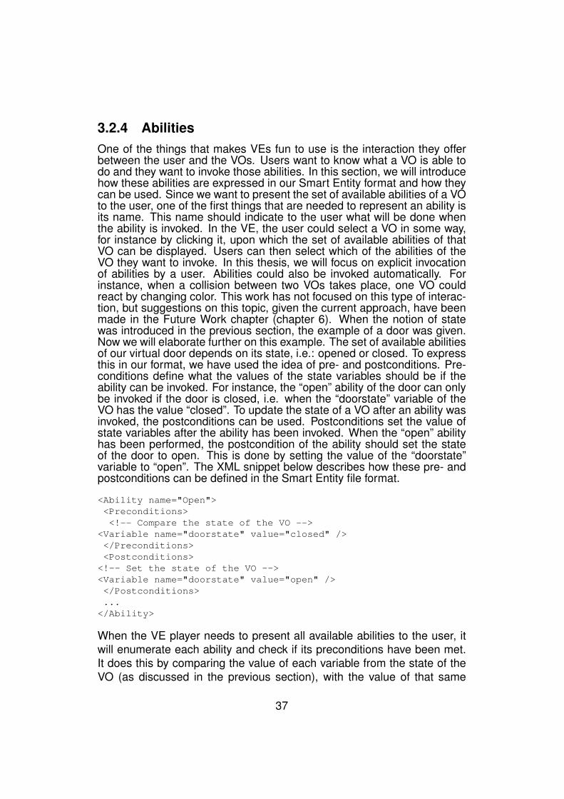
3.2.4 AbilitiesOne of the things that makes VEs fun to use is the interaction they offerbetween the user and the VOs. Users want to know what a VO is able todo and they want to invoke those abilities. In this section, we will introducehow these abilities are expressed in our Smart Entity format and how theycan be used. Since we want to present the set of available abilities of a VOto the user, one of the first things that are needed to represent an ability isits name. This name should indicate to the user what will be done whenthe ability is invoked. In the VE, the user could select a VO in some way,for instance by clicking it, upon which the set of available abilities of thatVO can be displayed. Users can then select which of the abilities of theVO they want to invoke. In this thesis, we will focus on explicit invocationof abilities by a user. Abilities could also be invoked automatically. Forinstance, when a collision between two VOs takes place, one VO couldreact by changing color. This work has not focused on this type of interac-tion, but suggestions on this topic, given the current approach, have beenmade in the Future Work chapter (chapter 6). When the notion of statewas introduced in the previous section, the example of a door was given.Now we will elaborate further on this example. The set of available abilitiesof our virtual door depends on its state, i.e.: opened or closed. To expressthis in our format, we have used the idea of pre- and postconditions. Pre-conditions define what the values of the state variables should be if theability can be invoked. For instance, the “open” ability of the door can onlybe invoked if the door is closed, i.e. when the “doorstate” variable of theVO has the value “closed”. To update the state of a VO after an ability wasinvoked, the postconditions can be used. Postconditions set the value ofstate variables after the ability has been invoked. When the “open” abilityhas been performed, the postcondition of the ability should set the stateof the door to open. This is done by setting the value of the “doorstate”variable to “open”. The XML snippet below describes how these pre- andpostconditions can be defined in the Smart Entity file format.
<Ability name="Open"><Preconditions><!-- Compare the state of the VO -->
<Variable name="doorstate" value="closed" /></Preconditions><Postconditions>
<!-- Set the state of the VO --><Variable name="doorstate" value="open" /></Postconditions>...
</Ability>
When the VE player needs to present all available abilities to the user, itwill enumerate each ability and check if its preconditions have been met.It does this by comparing the value of each variable from the state of theVO (as discussed in the previous section), with the value of that same
37
variable which has been asserted in the preconditions section. If all ofthese comparisons succeed, then the ability can be invoked by the user.When an ability has finished, for instance when the door has been opened,the postconditions will be set. To accomplish this, the VE player’s EngineExtension will enumerate all postconditions and set the state variables ofthe VO to the value that has been defined in these postconditions. Sosuppose we have invoked the “Open” ability, then the “doorstate” variable’svalue will be set to “open”. As a result, the precondition for “open” will nowfail and the “Open” ability will not be able to start again, unless the doorhas been closed and the “doorstate” has been set to “closed” by the closeability’s postconditions. The usage of abilities in the Smart Entity formatwill be explained further in the following section.
3.2.5 Behaviors
Let us take a closer look at the abilities of a VO. Suppose we are animat-ing a car. The car will have the ability to drive forward. To accomplishthis, the wheels of the car will need to rotate and at the same time the caritself will need to be moved (translated) forward. We can say that this abil-ity, “drive”, is composed of five behaviors: the rotations of the four wheelsand the translation of the car as a whole. Before this ability can be in-voked, we need some information on how and when these behaviors willbe performed. In the case of our car, the rotation and translation will startand stop at the same time. To spin the wheels, we need to rotate thema given amount of radians around their respective X-axes. To translatethe car, we need to translate the entire car a number of units along itsforward vector. We have now abstracted the behaviors away from theirimplementation. We have simply stated what should be done and whichparameters are needed in order to perform the behavior. This abstractionallows us to define abilities and their set of behavior invocations in an ab-stract way, without having to know how these behaviors are performed bythe VE player.
38

From the example that was given, we can deduce that each behaviorhas some required parameters:
1. Start: When the ability is executed, at what time will the behavior beinvoked.
2. Duration: What is the duration of the behavior invocation.
3. TargetBoneIDs: On which bones (geometric parts) of the VO will thebehavior be invoked. (ex. front wheel)
In addition to these three required attributes, a behavior invocation mightneed other parameters that define how it should be performed. Examplesof these are the rotation angle of the wheels of a car and the direction anddistance of the translation of the car. These parameters depend solelyon the behavior and its requested invocation and are unrelated to anyimplementation of these behaviors. By only stating the parameters andtheir values, the concrete implementation of these behaviors has beenabstracted away and we can express the abilities of a VO in a platform-independent way, this method will be referred to as the parameterizationof a behavior. As an example, consider a linear rotation behavior. The re-quired parameters are the start and duration times, the target parts of themodel (TargetBoneIDs) and the axis and angle of the rotation. Given theseparameters, the rotation behavior could be invoked regardless of the spe-cific implementation. The behavior could be implemented in Java for theJava3D [16] VE player, C# for Microsoft’s XNA VE player [17], JavaScriptfor Google’s O3D [36] VE player or by using any other programming lan-guage. Given this fact, we can identify a behavior implementation by whatit should do. We attach this identification to all VE player specific imple-mentations of that behavior. This identification has been called a behaviorGlobal Unique Identifier or GUID. For example, we might have some codein a Java Archive (JAR) file that contains specific code for Java3D andwhich performs a translation, given the correct parameters. We could alsohave JavaScript code which performs the translation in the same way, buton Google’s O3D VE player. These two behavior implementations will thenhave the same GUID. This GUID is an important aspect in our approachand is essential in providing behavior portability and reusability.
39
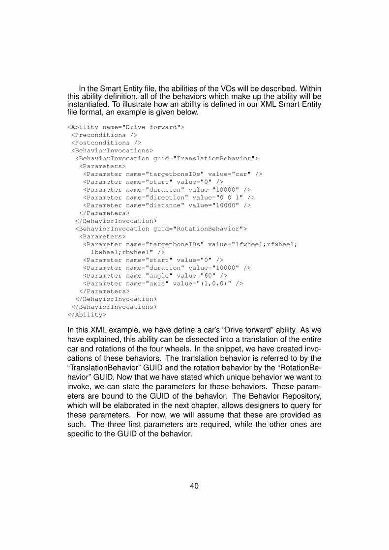
In the Smart Entity file, the abilities of the VOs will be described. Withinthis ability definition, all of the behaviors which make up the ability will beinstantiated. To illustrate how an ability is defined in our XML Smart Entityfile format, an example is given below.
<Ability name="Drive forward"><Preconditions /><Postconditions /><BehaviorInvocations><BehaviorInvocation guid="TranslationBehavior"><Parameters><Parameter name="targetboneIDs" value="car" /><Parameter name="start" value="0" /><Parameter name="duration" value="10000" /><Parameter name="direction" value="0 0 1" /><Parameter name="distance" value="10000" /></Parameters>
</BehaviorInvocation><BehaviorInvocation guid="RotationBehavior"><Parameters><Parameter name="targetboneIDs" value="lfwheel;rfwheel;
lbwheel;rbwheel" /><Parameter name="start" value="0" /><Parameter name="duration" value="10000" /><Parameter name="angle" value="60" /><Parameter name="axis" value="(1,0,0)" /></Parameters>
</BehaviorInvocation></BehaviorInvocations>
</Ability>
In this XML example, we have define a car’s “Drive forward” ability. As wehave explained, this ability can be dissected into a translation of the entirecar and rotations of the four wheels. In the snippet, we have created invo-cations of these behaviors. The translation behavior is referred to by the“TranslationBehavior” GUID and the rotation behavior by the “RotationBe-havior” GUID. Now that we have stated which unique behavior we want toinvoke, we can state the parameters for these behaviors. These param-eters are bound to the GUID of the behavior. The Behavior Repository,which will be elaborated in the next chapter, allows designers to query forthese parameters. For now, we will assume that these are provided assuch. The three first parameters are required, while the other ones arespecific to the GUID of the behavior.
40
3.2.6 Behavior LocatorsIn the previous section, we have described how we have abstracted awayfrom the concrete behavior implementation by means of parameterizationof the behavior invocations. Furthermore, we have used Global UniqueIdentifiers (GUIDs) to group behavior implementations which perform thesame behavior on different platforms. To provide portability, the conceptof Behavior Locators has been introduced in our Smart Entity file format.Here is an example of these Behavior Locators.
<BehaviorLocators><BehaviorLocator guid="rotate"
repositoryUri="http://localhost/BehaviorRepository.asmx"/><BehaviorLocator guid="translate"
repositoryUri="http://localhost/BehaviorRepository.asmx" /></BehaviorLocators>
Behavior Locators link GUIDs of behaviors to a Behavior Repository. ThisBehavior Repository can be seen as a database which contains all VEplayer specific implementations of behaviors, grouped by their GUID. Moreinformation on this Behavior Repository can be found in the next chapter.These locators are used by our proposed extension of the VE player: theEngine Extension. This extension will attempt to find the specific imple-mentation of the behavior for the VE player. This process is called Be-havior Resolution. If a VE player needs to perform a certain behavior, theextension will query these Behavior Locators to find the Behavior Repos-itory in which it can find the implementation. The extension will then askthe Behavior Repository for an implementation of the behavior for the VEplayer in question. This process will be elaborated in more detail in thenext chapter. For now, it is important to know that the Smart Entity fileindirectly contains the location of the VE player specific implementation ofall behaviors that are used in the file.
41
3.2.7 MembersA VO can be composed of many different parts, we call these complex VOs[50]. To group a set of logically related geometric parts (bones) of a VO, amember can be defined in our Smart Entity format. A member is a namedcomposition of strings which refer to the names of the bones that formthe group. This feature was conceived in order to ease reuse of logicallyrelated bones. An example could be a “wheels” member that consists outof all of a vehicle’s wheels. Designers that want to attach a behavior to thewheels can refer to all four wheels by using the name of the member as theTargetBoneIDs parameter of the behavior, the Engine Extension will thenreplace this member by the bones it represents. Members cannot havethe same name as a bone of the model. To illustrate how members aredefined in our Smart Entity file according to the XSD scheme (see 8.1), anexample is given below:
<Members><Member name="wheels">
<MemberBone id="wheelLF" /><MemberBone id="wheelRF" /><MemberBone id="wheelLB" /><MemberBone id="wheelRB" />
</Member></Members>
42
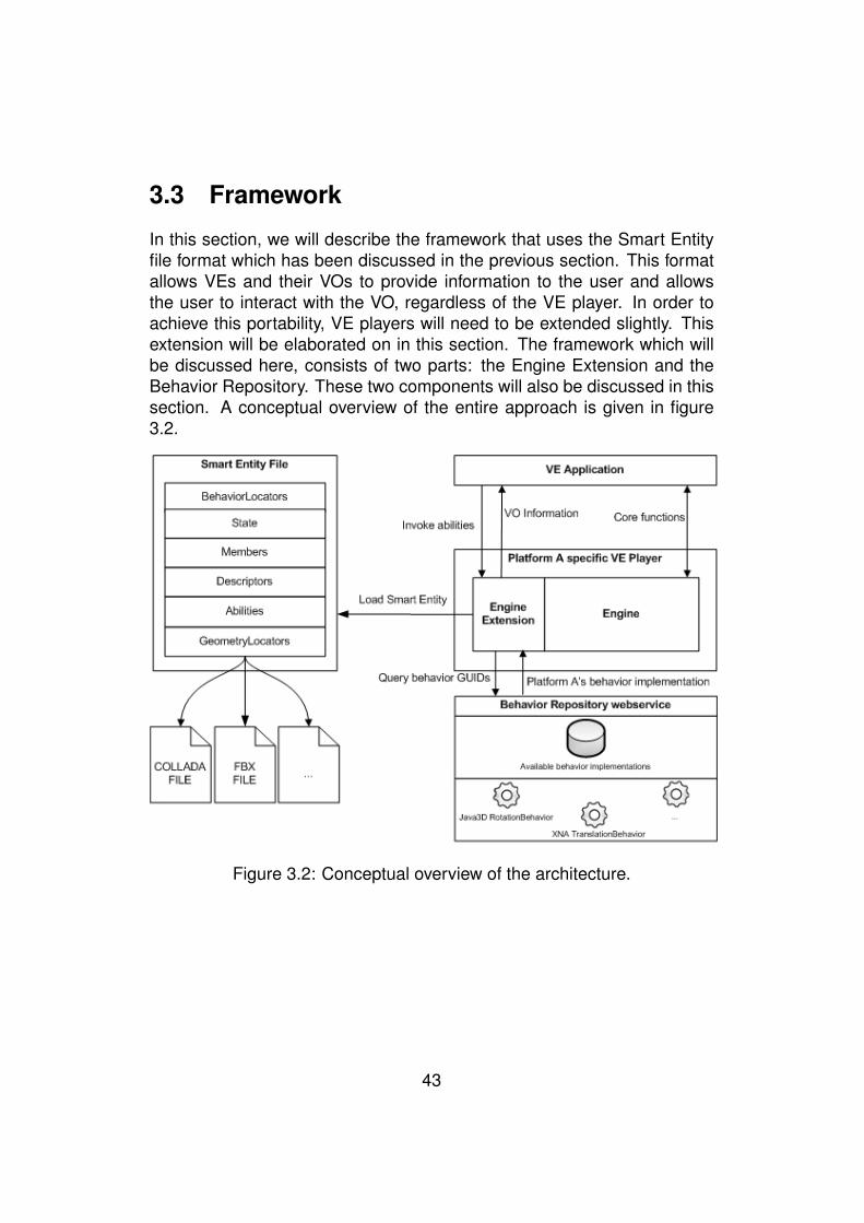
3.3 Framework
In this section, we will describe the framework that uses the Smart Entityfile format which has been discussed in the previous section. This formatallows VEs and their VOs to provide information to the user and allowsthe user to interact with the VO, regardless of the VE player. In order toachieve this portability, VE players will need to be extended slightly. Thisextension will be elaborated on in this section. The framework which willbe discussed here, consists of two parts: the Engine Extension and theBehavior Repository. These two components will also be discussed in thissection. A conceptual overview of the entire approach is given in figure3.2.
Figure 3.2: Conceptual overview of the architecture.
43
The main components of the framework are (1) an extension to exist-ing VE players and (2) the Behavior Repository webservice. Each of thesetwo components will be described in more details in this section. To designour framework, we have made two hypotheses. The first hypothesis is thatdevelopers of existing VE players will be willing to extend their VE players.We believe that we can persuade them to do so if they see all of the bene-fits that our approach can offer them and if the required changes are keptas minimal as possible. The second hypothesis is that the complete VE— its VOs and behaviors — will be annotated using our approach and thatthere will be a Smart Entity file for each VO in the VE. The next chapterwill describe an Authoring Tool that has been developed in order to allowdesigners to annotate these VOs in an efficient way.
In the previous section, the Smart Entity file format, which is depictedon the left side of the scheme, was discussed. This section will focus onthe right side of this scheme. An extension to the existing VE player will beelaborated. This extension will be responsible for loading the presentedSmart Entity file format. The VE application can then display the informa-tion about the VO in the virtual world.
Furthermore, the VE application can ask the Engine Extension to in-voke the abilities that were described in the Smart Entity file. In orderto accomplish this, the Behavior Repository webservice will be queried(Behavior Resolution) for obtaining a behavior implementation that is com-patible with the VE player and its platform. We will now discuss the com-ponents that make up the framework i.e.: the Engine Extension and theBehavior Repository.
44
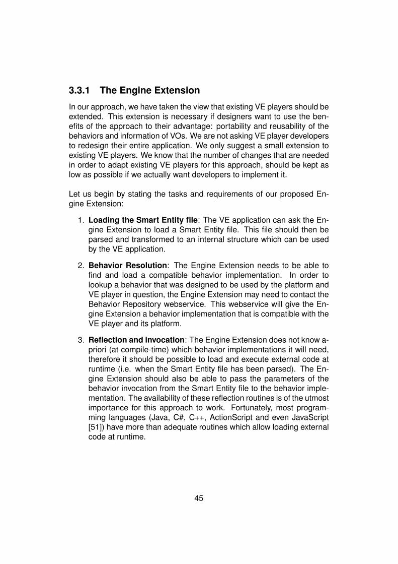
3.3.1 The Engine Extension
In our approach, we have taken the view that existing VE players should beextended. This extension is necessary if designers want to use the ben-efits of the approach to their advantage: portability and reusability of thebehaviors and information of VOs. We are not asking VE player developersto redesign their entire application. We only suggest a small extension toexisting VE players. We know that the number of changes that are neededin order to adapt existing VE players for this approach, should be kept aslow as possible if we actually want developers to implement it.
Let us begin by stating the tasks and requirements of our proposed En-gine Extension:
1. Loading the Smart Entity file: The VE application can ask the En-gine Extension to load a Smart Entity file. This file should then beparsed and transformed to an internal structure which can be usedby the VE application.
2. Behavior Resolution: The Engine Extension needs to be able tofind and load a compatible behavior implementation. In order tolookup a behavior that was designed to be used by the platform andVE player in question, the Engine Extension may need to contact theBehavior Repository webservice. This webservice will give the En-gine Extension a behavior implementation that is compatible with theVE player and its platform.
3. Reflection and invocation: The Engine Extension does not know a-priori (at compile-time) which behavior implementations it will need,therefore it should be possible to load and execute external code atruntime (i.e. when the Smart Entity file has been parsed). The En-gine Extension should also be able to pass the parameters of thebehavior invocation from the Smart Entity file to the behavior imple-mentation. The availability of these reflection routines is of the utmostimportance for this approach to work. Fortunately, most program-ming languages (Java, C#, C++, ActionScript and even JavaScript[51]) have more than adequate routines which allow loading externalcode at runtime.
45
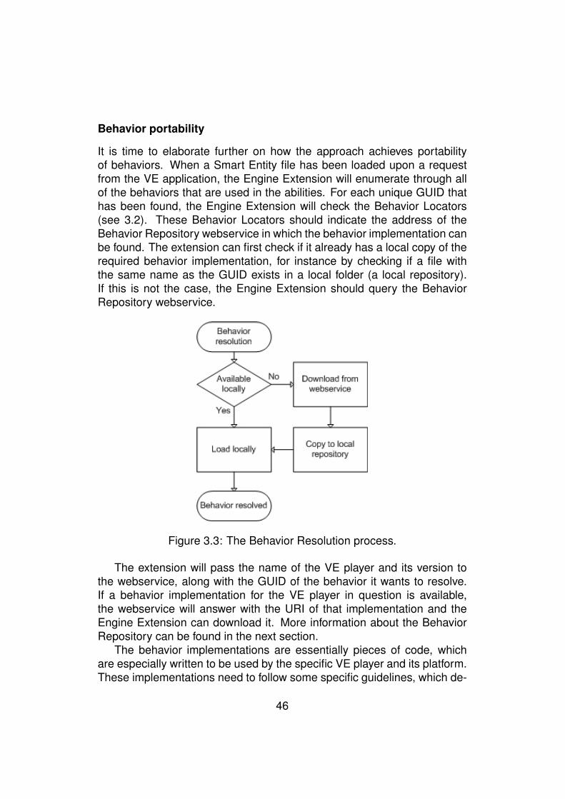
Behavior portability
It is time to elaborate further on how the approach achieves portabilityof behaviors. When a Smart Entity file has been loaded upon a requestfrom the VE application, the Engine Extension will enumerate through allof the behaviors that are used in the abilities. For each unique GUID thathas been found, the Engine Extension will check the Behavior Locators(see 3.2). These Behavior Locators should indicate the address of theBehavior Repository webservice in which the behavior implementation canbe found. The extension can first check if it already has a local copy of therequired behavior implementation, for instance by checking if a file withthe same name as the GUID exists in a local folder (a local repository).If this is not the case, the Engine Extension should query the BehaviorRepository webservice.
Figure 3.3: The Behavior Resolution process.
The extension will pass the name of the VE player and its version tothe webservice, along with the GUID of the behavior it wants to resolve.If a behavior implementation for the VE player in question is available,the webservice will answer with the URI of that implementation and theEngine Extension can download it. More information about the BehaviorRepository can be found in the next section.
The behavior implementations are essentially pieces of code, whichare especially written to be used by the specific VE player and its platform.These implementations need to follow some specific guidelines, which de-
46
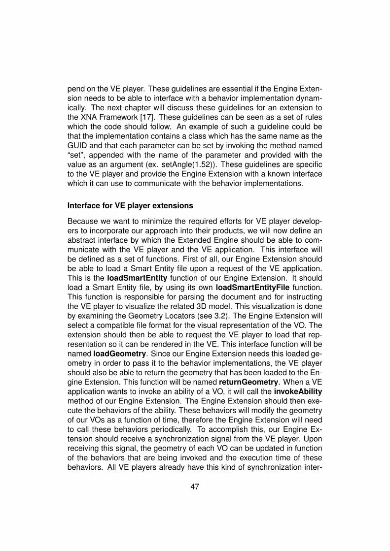
pend on the VE player. These guidelines are essential if the Engine Exten-sion needs to be able to interface with a behavior implementation dynam-ically. The next chapter will discuss these guidelines for an extension tothe XNA Framework [17]. These guidelines can be seen as a set of ruleswhich the code should follow. An example of such a guideline could bethat the implementation contains a class which has the same name as theGUID and that each parameter can be set by invoking the method named“set”, appended with the name of the parameter and provided with thevalue as an argument (ex. setAngle(1.52)). These guidelines are specificto the VE player and provide the Engine Extension with a known interfacewhich it can use to communicate with the behavior implementations.
Interface for VE player extensions
Because we want to minimize the required efforts for VE player develop-ers to incorporate our approach into their products, we will now define anabstract interface by which the Extended Engine should be able to com-municate with the VE player and the VE application. This interface willbe defined as a set of functions. First of all, our Engine Extension shouldbe able to load a Smart Entity file upon a request of the VE application.This is the loadSmartEntity function of our Engine Extension. It shouldload a Smart Entity file, by using its own loadSmartEntityFile function.This function is responsible for parsing the document and for instructingthe VE player to visualize the related 3D model. This visualization is doneby examining the Geometry Locators (see 3.2). The Engine Extension willselect a compatible file format for the visual representation of the VO. Theextension should then be able to request the VE player to load that rep-resentation so it can be rendered in the VE. This interface function will benamed loadGeometry. Since our Engine Extension needs this loaded ge-ometry in order to pass it to the behavior implementations, the VE playershould also be able to return the geometry that has been loaded to the En-gine Extension. This function will be named returnGeometry. When a VEapplication wants to invoke an ability of a VO, it will call the invokeAbilitymethod of our Engine Extension. The Engine Extension should then exe-cute the behaviors of the ability. These behaviors will modify the geometryof our VOs as a function of time, therefore the Engine Extension will needto call these behaviors periodically. To accomplish this, our Engine Ex-tension should receive a synchronization signal from the VE player. Uponreceiving this signal, the geometry of each VO can be updated in functionof the behaviors that are being invoked and the execution time of thesebehaviors. All VE players already have this kind of synchronization inter-
47
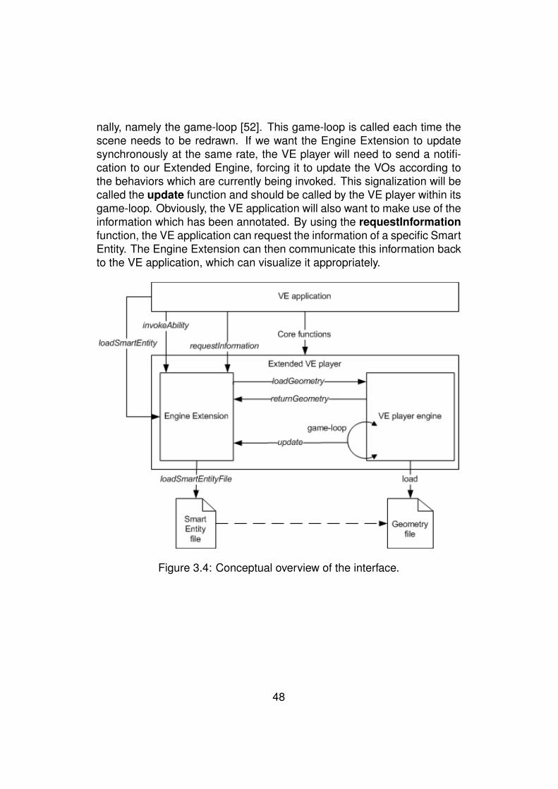
nally, namely the game-loop [52]. This game-loop is called each time thescene needs to be redrawn. If we want the Engine Extension to updatesynchronously at the same rate, the VE player will need to send a notifi-cation to our Extended Engine, forcing it to update the VOs according tothe behaviors which are currently being invoked. This signalization will becalled the update function and should be called by the VE player within itsgame-loop. Obviously, the VE application will also want to make use of theinformation which has been annotated. By using the requestInformationfunction, the VE application can request the information of a specific SmartEntity. The Engine Extension can then communicate this information backto the VE application, which can visualize it appropriately.
Figure 3.4: Conceptual overview of the interface.
48
To summarize, we have defined an abstract interface which defineshow communication between the VE player, its Engine Extension and theVE application should occur (see figure 3.4). We have defined the follow-ing set of functions:
• loadSmartEntity: The Engine Extension can be asked to load aSmart Entity.
• loadSmartEntityFile: This function will parse the Smart Entity fileinto an internal representation and will call the requestGeometr yfunction.
• requestInformation: The VE application can request information aSmart Entity, for instance its descriptors and available abilities. Thisinformation can then be displayed within the VE.
• loadGeometry: The VE player should provide a function which loadsthe actual geometry of the Smart Entity from a file which is compat-ible with the VE player. This file is chosen by the Engine Extensionby examining the entity’s Geometry Locators.
• returnGeometry: This function returns the geometry of the VO fromthe VE player to the Engine Extension, so the behaviors can updateit.
• invokeAbility: This function can be called by the VE application if itneeds to execute an ability of the Smart Entity.
• update: This function of the Extended Engine is called periodicallyby the VE player’s game-loop. It will enumerate all of the abilitiesof the VO and their abilities which are being performed. For eachability, its behaviors will be updated in terms of the time the ability isrunning.
49

3.3.2 Behavior Repository
All of the platform-specific behavior implementations reside in a centralrepository. This is the Behavior Repository. Ideally, it holds references(URIs) to all implementations of behaviors for all different VE players, oth-erwise some behaviors cannot be invoked on certain VE players. The En-gine Extension can query this repository because it can retrieve its addressfrom the Behavior Locators within the Smart Entity file. These locators linkbehavior GUIDs to the URI of a Behavior Repository. When the Engine Ex-tension queries the Behavior Repository for a specific behavior implemen-tation, it sends its VE player code (ex. XNA, Java3D, O3D) and the versionnumber of the VE player (ex. 3.0) along with the GUID of the behavior. Therepository will respond with a URI to the behavior implementation for thatVE player. Along with references to implementations, the repository alsocontains information about behaviors. This information is specific to eachbehavior GUID. As an example, consider the behavior with GUID “Rotate-Linear”. When queried with a GUID, the Behavior Repository can answerwith the information it has about that behavior. This information containsa description of this GUID, a list of VE players for which it has a specificbehavior implementation and the list of parameters this behavior requires,as well as a description per parameter and the types of the parameters.
This information can be used by authoring tools, like the one that will bepresented in the next chapter, in order to help designers of VOs. Design-ers can then browse the repository, select a behavior they want to use andreceive information on how they should use the behavior. For example, adesigner wants to perform a rotation of the turret of a tank. The designercan then query the Behavior Repository for all of its available behaviors.The designer can select the RotateLinear behavior and use it. The author-ing tool can then request additional information about the behavior in orderto assist the designer. This way, the designer can see that the angle thatis needed should be expressed in radians and that the rotation axis shouldbe expressed as a vector in 3D space.
From the example that was given, we can deduce that the parametersof a behavior have types associated with them. In order to maintain porta-bility, the values of these parameters should be expressed in an identicalway for each type. The Engine Extension can then convert the valuesof the parameters to the types that are needed by the concrete BehaviorImplementation.
50

Below is a list of the proposed data types of the parameters.
• String: Simple textual content, represented as text.
• String[]: An array of Strings, represented as each String separatedby a semi-colon. This is the type of the required TargetBoneIDsparameter. Example: “part1;part2”
• Number: Represents a number, examples are the Star t and Durationparameters.
• Boolean: Represents a boolean value. Represented as “True” or“False”
• Vector3: Represents a triple of numbers. Grouped within roundbrackets and separated by a comma. Example: “(1,2,3)”).
These types are used to indicate the type of the parameters to the Author-ing Tool and to the user. The Authoring Tool can then provide an easyway of entering an array of strings or vectors. The Engine Extension willpass the values of the parameters to the behavior implementation. Sincethe value of the parameters are expressed as strings, it is then necessaryto transform these strings to platform specific structures, such as XNA’sVector3 class or Java3D’s Double class.
51
By centralizing all available behavior implementations and by provid-ing a platform-independent interface by means of a webservice, severaladvantages have been achieved:
• Increased behavior reusability: Designers can make use of thesame behavior implementation and the available behaviors can bebrowsed by a designer. This way, a designer only needs to specifythe parameters of a behavior, while the concrete implementation hasbeen done by programmers.
• Increased portability: The Behavior Repository provides a central-ized point of access for all VE players on different platforms. Byquerying this repository, the Engine Extension can obtain the com-patible behavior implementation. This way, Smart Entities could evenbe loaded at run-time by the VE player.
• New behaviors can be added: Because the Behavior Repositoryis an open medium, behavior implementations can be added, uponwhich they can be used by designers.
• Existing behaviors can be updated: Existing behaviors can betuned to achieve a better performance or to eliminate bugs. To ac-complish this, the Engine Extension could regularly check if updatedimplementations of the behaviors in its local repository are available.
52
Chapter 4
Implementation of the AuthoringTool and the Framework
The first part of this chapter will explain the Authoring Tool that has beendeveloped in order to facilitate the creation of Smart Entities. The mainfeatures and the implementation of this tool will be discussed. The sec-ond part will elaborate on the Microsoft XNA Engine Extension that hasbeen developed. The VE player that was chosen for this extension wasMicrosoft’s XNA 3.0. The third and last part of this chapter will talk aboutthe implementation of the Behavior Repository webservice.
4.1 Authoring Tool
4.1.1 General design
Obviously, we cannot expect designers to create and edit Smart Entities byaltering the Smart Entity XML file format directly. In order to facilitate thistask, an Authoring Tool has been developed which will enable designersto both create and edit the Smart Entity files in an attractive visual envi-ronment. The Authoring Tool that will be presented in this section is theprototype of a target-platform independent, Smart Entity editor. Meaningthat the Smart Entity files which are created by using this Authoring Toolshould not refer to specific behavior implementations but to the GUID thatis attached to each behavior and to the Behavior Repository webserviceon which the behavior with that GUID was found.
53
The Authoring tool provides the following functionalities:
1. Create, read and edit Smart Entity files: A user is able to createnew Smart Entity files or can alter existing ones.
2. Attach and detach Geometry Locators: When a file is loaded, Ge-ometry Locators (see 3.2) can be attached and detached.
3. Visualization of the work: Users can preview their work easily, re-sulting in a faster and more efficient production process.
4. Manage descriptors: Users are able to add descriptors to the SmartEntity by entering the key, value, type and visibility of the descriptor.They can also update or remove existing descriptors.
5. Manage abilities: Users can add abilities by providing a name. Abil-ities can also be removed or their name can be changed.
6. Manage a set of available behaviors: The application has its ownrepository of behaviors which contains the location of the BehaviorRepository webservice where the behavior can be found and the pa-rameters the behavior requires. The user can add behaviors to theapplication’s repository or remove them.
7. Manage behaviors per ability: Users can select a behavior fromthe Behavior Repository, attach it to the ability and define the be-havior’s parameters (such as Start, Duration, TargetBoneIDs, etc.).Behaviors can also be updated or removed from the ability.
8. Manage Behavior Locators behind the scenes: When a new be-havior is added to an ability, the application will update the BehaviorLocators. The behavior’s GUID will be added, along with the linkto the Behavior Repository webservice where it can be found. If abehavior is removed (all instances of that behavior), the matchingBehavior Locator is deleted.
9. Manage State: The user should be able to add state variables to anentity and assign an initial value to those variables.
10. Manage Pre- and Postconditions: The user is able to specify theconditions (state variables) under which an ability can be performed,i.e. the preconditions. User should also be able to define postcon-ditions, which update the state of the entity when an ability has fin-ished.
54
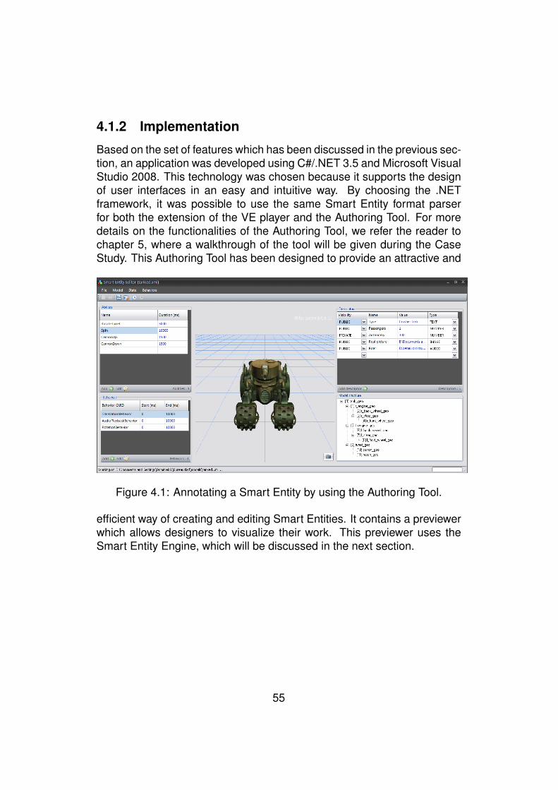
4.1.2 Implementation
Based on the set of features which has been discussed in the previous sec-tion, an application was developed using C#/.NET 3.5 and Microsoft VisualStudio 2008. This technology was chosen because it supports the designof user interfaces in an easy and intuitive way. By choosing the .NETframework, it was possible to use the same Smart Entity format parserfor both the extension of the VE player and the Authoring Tool. For moredetails on the functionalities of the Authoring Tool, we refer the reader tochapter 5, where a walkthrough of the tool will be given during the CaseStudy. This Authoring Tool has been designed to provide an attractive and
Figure 4.1: Annotating a Smart Entity by using the Authoring Tool.
efficient way of creating and editing Smart Entities. It contains a previewerwhich allows designers to visualize their work. This previewer uses theSmart Entity Engine, which will be discussed in the next section.
55
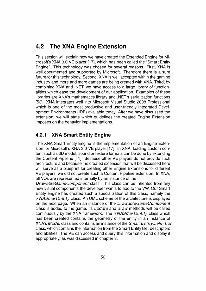
4.2 The XNA Engine Extension
This section will explain how we have created the Extended Engine for Mi-crosoft’s XNA 3.0 VE player [17], which has been called the “Smart EntityEngine”. This technology was chosen for several reasons. First, XNA iswell documented and supported by Microsoft. Therefore there is a surefuture for this technology. Second, XNA is well accepted within the gamingindustry and more and more games are being created with XNA. Third, bycombining XNA and .NET, we have access to a large library of function-alities which ease the development of our application. Examples of theselibraries are XNA’s mathematics library and .NET’s serialization functions[53]. XNA integrates well into Microsoft Visual Studio 2008 Professionalwhich is one of the most productive and user-friendly Integrated Devel-opment Environments (IDE) available today. After we have discussed theextension, we will state which guidelines the created Engine Extensionimposes on the behavior implementations.
4.2.1 XNA Smart Entity Engine
The XNA Smart Entity Engine is the implementation of an Engine Exten-sion for Microsoft’s XNA 3.0 VE player [17]. In XNA, loading custom con-tent such as 3D model, sound or texture formats can be done by extendingthe Content Pipeline [41]. Because other VE players do not provide sucharchitecture and because the created extension that will be discussed herewill serve as a blueprint for creating other Engine Extensions for differentVE players, we did not create such a Content Pipeline extension. In XNA,all VOs are represented internally by an instance of theDrawableGameComponent class. This class can be inherited from anynew visual components the developer wants to add to the VW. Our SmartEntity engine has created such a specialization of this class, namely theXNASmar tEntity class. An UML scheme of the architecture is displayedon the next page. When an instance of the DrawableGameComponentclass is added to the game, its update and draw methods will be calledcontinuously by the XNA framework. The XNASmar tEntity class whichhas been created contains the geometry of the entity in an instance ofXNA’s Model class and contains an instance of the Smar tEntityDefinit ionclass, which contains the information from the Smart Entity file: descriptorsand abilities. The VE can access and query this information and display itappropriately, as was discussed in chapter 3.
56
Figure 4.2: The Smart Entity in the XNA Framework.
Furthermore, the game can perform an ability of a Smart Entity by call-ing the invokeAbil i ty method of the XNASmar tEntity instance, in orderto help explain how this is accomplished, the scheme display in figure 4.3can be of help while reading.
When the invokeAbil i ty method is called, the Smart Entity Engine willfirst check to see if the preconditions are met, given the current state ofthe object. This is done by comparing all of the variables values that werestated in the preconditions with the actual values of the entity’s state (seechapter 3). When the preconditions are met, a new instance of theXNAAbil i ty Instance class will be created. Upon creation, the ability’s def-inition will be iterated and for each behavior invocation that is used, an in-stance of XNABehavior Instance will be added to the Behavior Instanceslist. The XNABehavior Instance will first construct an instance of theplatform-specific behavior implementation (ex. RotationBehavior ), whichhas been fetched during the Behavior Resolution (see 3.3), and will thenset the instance’s parameters according to those in the Smart Entity file.The values of the parameters in the definition will first be converted to XNAspecific structures by using a type-conversion mechanism. This mecha-
57

Figure 4.3: Propagation of updates in the game-loop.
nism first checks which datatype the behavior implementation expects andthen attempts to transform the string value from the Smart Entity file’s be-havior invocation parameter to that type. When the XNABehavior Instanceinstances have been created, the XNAAbil i ty Instance will be added tothe collection of running abilities in the XNASmar tEntity instance. Sinceall off the required behavior implementations have been resolved when theSmart Entity file was loaded, no more lookups need to occur and this pro-cess can be performed fast. During the game-loop, the update method ofthe XNASmar tEntity instance will be called at regular intervals. Duringeach call to update, the XNASmar tEntity instance will loop through all ofthe abilities which are currently being performed (RunningAbil i t ies mem-ber) and call the update method on those XNAAbil i ty Instance instances(1). Within this method, the update method of all XNABehavior Instanceinstances in the Behavior Instances member will be invoked (2). Thisupdate method will set the Posit ion field of the dynamically loaded be-havior implementation and will call the update method of the dynamic in-stance if necessary (star t ≤ Posit ion ≤ star t + duration) (3). It is thisinstance that is responsible for updating the model’s geometry and actu-ally performing the behavior. More information on the way these behaviorsare implemented can be found in the next sections. When an ability has
58
finished, so when all of the behavior instances have finished, the SmartEntity engine will set the state variables of the entity according to the post-conditions of the Smart Entity, thereby updating the state the entity is in.
4.2.2 Smart Entity engine interface
In chapter 3, we have proposed an interface for the VE player extensions.In this section, we will provide an overview of how our XNA Smart Entityengine implements this interface.
• loadSmartEntity: The VE application which uses our XNA SmartEntity can request our Smart Entity engine to load a Smart Entityfile. The engine will then load the information from the file and createa new instance of the XNASmar tEntity class. This instance willthen be returned.
• loadSmartEntityFile: This function will be called by the Smart En-gine extension and will parse our Smart Entity file into an object-oriented representation. We have created a parser which is decou-pled from the Microsoft XNA framework and which could be used byother .NET based applications (like our Authoring Tool).
• requestInformation: All of the information from our Smart Entity fileis available within an instance of the XNASmar tEntity class. Thisinstance has been returned by the loadSmar tEntity function.
• loadGeometry: Our Smart Entity engine will enumerate all Geome-try Locators of the Smart Entity file and will ask the XNA frameworkto load either a DirectX or FBX file, depending on which one is avail-able.
• returnGeometry: The XNA framework will return an instance of itsModel class, which holds the necessary geometry and which is en-capsulated in the XNASmar tEntity instance.
• invokeAbility: The XNASmar tEntity instance provides a methodwhich can invoke an ability by passing its name as an argument. Thisprocess is described in more detail in 4.2.1.
• update: In XNA, adding code to the game-loop is easy. By inher-iting from the DrawableGameComponent class, implementing theDraw and Update methods and adding the instance to the game’sComponents attribute the Draw and Update methods will be called
59
periodically. For more information on this implementation, please see4.2.1.
4.2.3 Behavior implementation guidelines
Before any Engine Extension can load code at runtime by using reflec-tion techniques [51], the code in question should be created with someguidelines in mind. These guidelines can be seen as the specification ofan interface between the Engine Extension and the behavior implemen-tations. This interface allows these two components to interact with eachother. For our XNA Smart Entity engine and its behaviors, we have statedthe following guidelines:
1. The file which contains the platform-specific implementation has theformat “guid.dll”, in which guid represents the GUID of the behavior.(ex. rotationbehavior.dll)
2. The name of the class which implements the behavior is the sameas the GUID.
3. The constructor of that class accepts two parameters: an instanceof the Game class, which is an XNA specific class that contains in-formation on the rendering and context. The second parameter isthe Model class. This class is also specific to XNA and contains thegeometric data of the model: its bones and transformation matrices.It is important to know that these matrices are passed by reference.
4. The parameters are applied to the behavior implementation instanceby setting fields. These fields are the way to define data accessorsin C# [54]
5. The behavior implementation contains an update method, which takesno parameters. This method will be called when the behavior needsto be invoked. It is within this method that the actual modification ofthe geometry in function of time can take place.
6. Before the update method is called, the Smart Entity Engine will setthe Position field of the behavior implementation to the elapsed time(in milliseconds), since the ability was invoked.
When a behavior implementation is created with these guidelines in mind,our Smart Entity Engine is able to load the behavior dynamically and can
60
interface with it. To facilitate the creation of new behavior implementa-tions, a template class has been designed which can be inherited from.This code, as well as the code for the TranslationBehavior and Rotation-Behavior can be found in the appendix (8.4). The guidelines that werestated were specifically conceived for our Smart Entity engine, but theycan be generalized towards other object-oriented environments, such asJava or C++.
4.3 Behavior Repository
The Behavior Repository is implemented as an ASP.NET 3.5 webservice(.asmx). Using a webservice promotes the interoperability we wish tostrive for. The webservice exposes its capabilities by using a WSDL (Web-service Description Language) scheme and uses SOAP (Simple ObjectAccess Protocol) to transfer its information to clients (an Engine Extensionor an Authoring Tool), both of these standards are supported across mostof the platforms that are in use today The information on the behaviorsthemselves is stored using a plain XML file that has the following struc-ture:
<Behavior guid="RotationBehavior"description="Perform a linear rotation"><Parameters><Parameter name="TargetBoneIDs" type="String[]"
description="" /><Parameter name="Duration" type="Number"
description="" /><Parameter name="Start" type="Number"
description="" /><Parameter name="Angle" type="Number"
description="The angle in radians" /><Parameter name="Axis" type="Vector3"
description="The axis of rotation" /></Parameters>
</Behavior>
<Player code="Java3D" version="1.3"><BehaviorLocation guid="RotationBehavior"uri="http://.../java3d/13/RotationBehavior.jar" />
</Player><Player code="XNA" version="2.0">
<BehaviorLocation guid="RotationBehavior"uri="http://.../xna/20/RotationBehavior.dll" />
</Player>
61

The Behavior Repository webservice exposes three web-methods:
• DescribeBehavior(guid): Returns the description of the behavioridentified by the GUID parameter, independent of the platform. Thisis the description of the behavior, along with the parameters that areneeded, their descriptions and their datatypes.
• FindBehavior(guid, playerCode, playerVersion): This method isto be invoked by the Engine Extension. The extension will contactthe webservice with the GUID of the behavior it needs to invoke, theplayerCode (name of the VE player) and the version of the player.The repository will respond with the description of the behavior anda URI for the behavior implementation (code file) for that VE player,if available.
• ListAvailableBehaviors(): Returns a list of descriptions for all thebehaviors that are available in the Behavior Repository. This methodis mainly used by the Authoring Tool to provide means of browsingand exploring the Behavior Repository to the designer.
Upon a request, the XML file is parsed by the Behavior Repository web-service and the data-structures (defined in the WSDL) are passed on tothe client using SOAP.
62
Chapter 5
Case study
To demonstrate the approach that was presented in this work and the tech-niques that were developed, a case study will be presented.
5.1 Outline
In this case study, we will be creating a VE application and its content fromscratch. More concretely, we will develop an application that will displaya cellphone in a 3D environment. The main purpose of this environmentis promotion. As several research papers have shown, a company canbenefit greatly from these promotional 3D environments (see [55], [56][57]). We want to deliver the annotations (information) which we will add tothe VO of the cellphone by using the Authoring Tool and allow some basicinteraction with the VO. Furthermore, it should be possible to reuse theenvironment for different cellphones and we should be able to reuse thecellphone on different VE players like Google’s O3D [36]. We will modelthe 3D representation, create a Smart Entity file (see 3.2) by using thepresented Authoring Tool(see 4.1), use the Smart Entity Engine (see 4.2)to load and use this file and finally create the VE application itself. In orderto deliver a rich user experience, we will also add some requirements tothe environment:
1. Users should be able to view the cellphone from different perspec-tives, the cellphone can be rotated and zoomed into.
2. The specifications of the cellphone should be displayed in the top-leftcorner.
3. Images should be shown at the right of the screen.
63
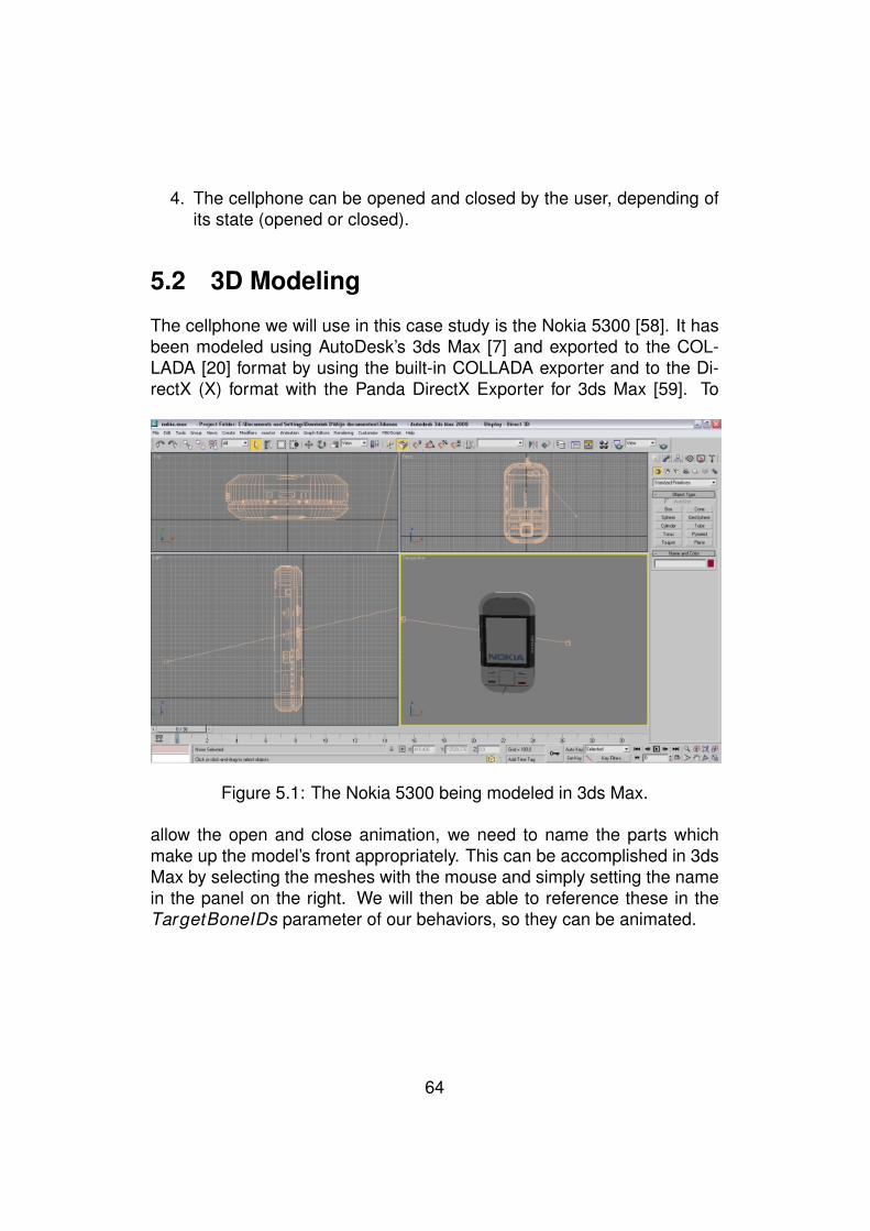
4. The cellphone can be opened and closed by the user, depending ofits state (opened or closed).
5.2 3D Modeling
The cellphone we will use in this case study is the Nokia 5300 [58]. It hasbeen modeled using AutoDesk’s 3ds Max [7] and exported to the COL-LADA [20] format by using the built-in COLLADA exporter and to the Di-rectX (X) format with the Panda DirectX Exporter for 3ds Max [59]. To
Figure 5.1: The Nokia 5300 being modeled in 3ds Max.
allow the open and close animation, we need to name the parts whichmake up the model’s front appropriately. This can be accomplished in 3dsMax by selecting the meshes with the mouse and simply setting the namein the panel on the right. We will then be able to reference these in theTargetBoneIDs parameter of our behaviors, so they can be animated.
64

5.3 Creating the Smart Entity file
To create the Smart Entity file, we will use the presented Authoring Tool(see 4.1). We start by creating a new Smart Entity file. We will first attachthe cellphone models (COLLADA and DirectX) to the file. The previewerwill then visualize the model (DirectX format) in the Authoring Tool. Thenwe can start annotating our Smart Entity by adding the descriptors. Thedescriptors can be seen in the right upper corner of the application. Fivetextual descriptors and four images of the cellphone have been added. Inorder to add abilities to the entity, we will need to have some availablebehaviors to work with. For this, we will use the Authoring Tool’s Behav-ior Explorer to browse a Behavior Repository webservice. The Behavior
Figure 5.2: The Authoring Tool’s Behavior Explorer.
Explorer allows users to add a behavior they found to Authoring Tool’stoolbox of available behaviors. This toolbox is maintained by the Author-ing Tool itself and allows reuse of behaviors. Using the Behavior Explorer,we have added both the translation- and rotation-behaviors to the toolbox.The XML file which has been created by the Authoring Tool, can be seenin the Appendix (see 8.2)).
65
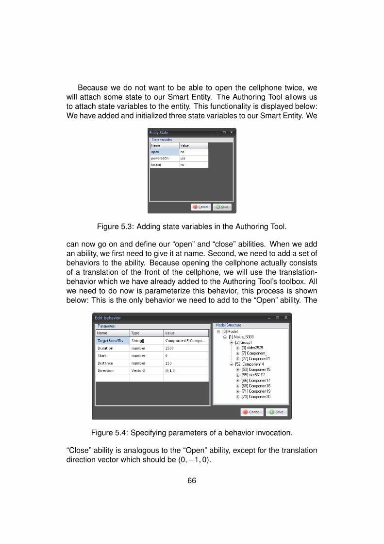
Because we do not want to be able to open the cellphone twice, wewill attach some state to our Smart Entity. The Authoring Tool allows usto attach state variables to the entity. This functionality is displayed below:We have added and initialized three state variables to our Smart Entity. We
Figure 5.3: Adding state variables in the Authoring Tool.
can now go on and define our “open” and “close” abilities. When we addan ability, we first need to give it at name. Second, we need to add a set ofbehaviors to the ability. Because opening the cellphone actually consistsof a translation of the front of the cellphone, we will use the translation-behavior which we have already added to the Authoring Tool’s toolbox. Allwe need to do now is parameterize this behavior, this process is shownbelow: This is the only behavior we need to add to the “Open” ability. The
Figure 5.4: Specifying parameters of a behavior invocation.
“Close” ability is analogous to the “Open” ability, except for the translationdirection vector which should be (0,−1, 0).
66

When this is done, we can specify the pre- and postconditions of theabilities. This process is shown below. The precondition that is depicted
Figure 5.5: Specifying post- and preconditions for the “Open” behavior.
states that the cellphone cannot be opened when it is already openedand that the “open” state variable’s value should change to “yes” when theability was performed. This concludes the creation of the Smart Entity fileby using the Authoring Tool, we can now save this file to disk and our VEapplication will be able to load it.
Figure 5.6: The main window of the Authoring Tool.
67
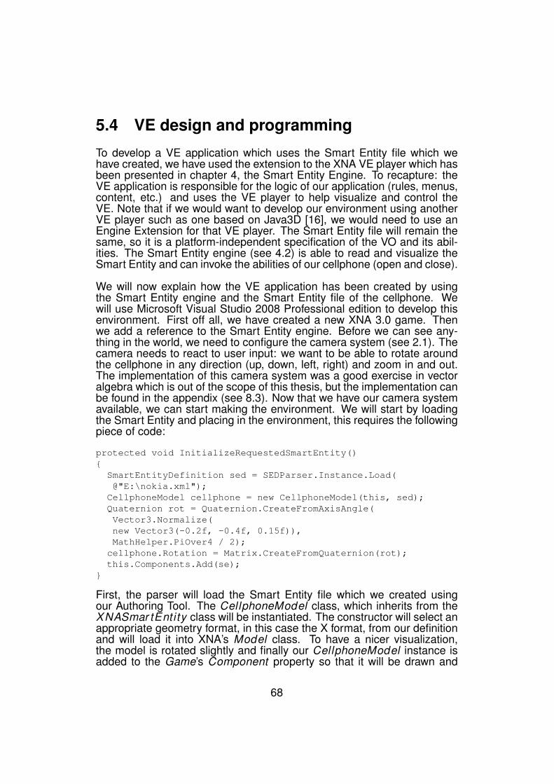
5.4 VE design and programming
To develop a VE application which uses the Smart Entity file which wehave created, we have used the extension to the XNA VE player which hasbeen presented in chapter 4, the Smart Entity Engine. To recapture: theVE application is responsible for the logic of our application (rules, menus,content, etc.) and uses the VE player to help visualize and control theVE. Note that if we would want to develop our environment using anotherVE player such as one based on Java3D [16], we would need to use anEngine Extension for that VE player. The Smart Entity file will remain thesame, so it is a platform-independent specification of the VO and its abil-ities. The Smart Entity engine (see 4.2) is able to read and visualize theSmart Entity and can invoke the abilities of our cellphone (open and close).
We will now explain how the VE application has been created by usingthe Smart Entity engine and the Smart Entity file of the cellphone. Wewill use Microsoft Visual Studio 2008 Professional edition to develop thisenvironment. First off all, we have created a new XNA 3.0 game. Thenwe add a reference to the Smart Entity engine. Before we can see any-thing in the world, we need to configure the camera system (see 2.1). Thecamera needs to react to user input: we want to be able to rotate aroundthe cellphone in any direction (up, down, left, right) and zoom in and out.The implementation of this camera system was a good exercise in vectoralgebra which is out of the scope of this thesis, but the implementation canbe found in the appendix (see 8.3). Now that we have our camera systemavailable, we can start making the environment. We will start by loadingthe Smart Entity and placing in the environment, this requires the followingpiece of code:
protected void InitializeRequestedSmartEntity(){
SmartEntityDefinition sed = SEDParser.Instance.Load(@"E:\nokia.xml");
CellphoneModel cellphone = new CellphoneModel(this, sed);Quaternion rot = Quaternion.CreateFromAxisAngle(Vector3.Normalize(new Vector3(-0.2f, -0.4f, 0.15f)),MathHelper.PiOver4 / 2);
cellphone.Rotation = Matrix.CreateFromQuaternion(rot);this.Components.Add(se);
}
First, the parser will load the Smart Entity file which we created usingour Authoring Tool. The CellphoneModel class, which inherits from theXNASmar tEntity class will be instantiated. The constructor will select anappropriate geometry format, in this case the X format, from our definitionand will load it into XNA’s Model class. To have a nicer visualization,the model is rotated slightly and finally our CellphoneModel instance isadded to the Game’s Component property so that it will be drawn and
68
updated in the game-loop. Next thing we want to do is to process theSmart Entity’s descriptors and display them in the VE. We will display allpublic descriptors of type Text in the left upper corner. An example wouldbe “Manufacturer:Nokia”. We will also display all public descriptors of typeImage. These will be positioned on the right of the display. The code thatis needed to accomplish this is display below:
public void DisplayImages() {Vector2 position = new Vector2(
this.Window.ClientBounds.Width - 250, 150);
foreach (DescriptorDefinition imgDesc inCellphone.Definition.SelectDescriptors(
VisiblilityTypes.PUBLIC, ContentTypes.IMAGE)){ImageOverlay overlay = new ImageOverlay(this,
spriteBatch,imgDesc.Value,position);
position += new Vector2(0, 135);Components.Add(overlay);}
}
The descriptors collection can be queried by providing two parameters: thevisibility and the type of the descriptors. For each public image descrip-tor, an ImageOver lay instance will be added to the scene’s components.This ImageOver lay class will draw this image on the right of the screen,at the offset specified by the posit ion variable. Another requirement wasthe display of the cellphone’s specifications in the top left corner of thescreen. This is accomplished in about the same way as the images. In-stead of images, we will query for text and instead of the ImageOver layinstance, we will add a TextOver lay to the Components property. Usingthe Authoring Tool, we have created two abilities: “open” and close. If auser presses the Enter key, we want the cellphone to open if closed andvice versa. In order to make this possible, we will add a Toggle method toour CellphoneModel class. Within this method, we will check the state ofthe entity and start the appropriate ability.
public void Toggle(){if (IsOpen())InvokeAbility("close");elseInvokeAbility("open");
}
That is it for the VE design and programming part. We can now visualizeour environment.
69

5.5 Result
Figure 5.7: The opened cellphone in our created environment.
Above, a screenshot of the created environment is shown. Our Author-ing Tool (see 4.1) has been used for the creation of our Smart Entity. Thistool provides an easy to use front-end so that anyone can create new oralter existing Smart Entity files. Furthermore, the Authoring Tool has al-lowed us to browse a Behavior Repository (see 4.3) and has let us usethe available behaviors in our Smart Entity file. We have also created anattractive virtual promotion environment. By using the Smart Entity engine(see 4.2), we were able to use our created Smart Entity file. We have usedthe typed descriptors (images and text) and have relied on the XNA SmartEntity engine to perform abilities (open, close) for us, simply by executingthe invokeAbil i ty method. The approach we have taken has given ussome benefits. For instance, we can still change our Smart Entity file andthe changes will be reflected in our VE without recompilation. We couldadd specifications, add images, create new abilities, etc. We can alsoreuse our Smart Entity file in other virtual environments, without changingit, and even on different VE players, if an Engine Extension is available forthat player. The entire scene could also be reused for other cellphones,requiring none or minimal changes to the code of the VE application.
70
Chapter 6
Future work
The work that has been presented in this thesis is far from being complete,therefore this chapter will suggest a number of possible improvements.
Allowing Smart Entity interaction.
The current approach does not enable interaction between Smart Entitiesin the VE. For instance, when one entity collides with the other, the firstcould change color. Adding these kinds of triggers to our Smart Entityformat would not pose a problem, but in order to use these triggers theinterface of the Engine Extension, which was presented in 3.3 should beextended. The VE player could monitor events in the VE (collisions, mouseand keyboard interaction, etc.) and then trigger an event function on theExtended Engine, ex. eventOccured . The VE player could then decidewhat should be done, depending on the Smart Entities which triggered theevent.
Improving the Authoring Tool
As with any application, the Authoring Tool can always be improved fur-ther. The current version of the Authoring Tool depends on the user tochoose the right sequence of behaviors. A more advanced tool could useConstraint Solving techniques [60] to calculate the correct sequence andparameters. The functionalities of the tool could also be improved, for in-stance the abilities could be shown as a timeline. This would provide abetter overview of the ability to the user. The tool could also provide morehelp to users while they adjust the parameters of a behavior. Some aidcould be given when the user has to enter an angle or a vector, which
71

would also lower the level of knowledge that is needed in order to workwith the tool.
Creating an Engine Extension for another VE player
In this work, we have created a concrete implementation of our proposedEngine Extension for Microsoft’s XNA framework. In order to fully test in-teroperability, another extension for an existing VE player could be made.A proof of concept Engine Extension the uses Google’s O3D framework[36] is being developed at the time of writing, but since this technologywas only released by the end of April and because large parts of the doc-umentation are not yet available, this second Engine Extension could notyet be presented in this work. A screenshot of the proof of concept can beseen in figure 6.1.
Figure 6.1: A limited prototype of the approach using Google O3D.
72
Chapter 7
Conclusion
Currently, the annotations that are supported by existing authoring toolsare often text based and they are only related to the static part of a VO.Our approach has shown that it is possible to also annotate the dynamicpart of a VO i.e. its behaviors and interactions. This was the first aim ofthe thesis.
By annotating behaviors and by knowing the behaviors that are associ-ated to a VO, we were also capable of stating what a VO can do. This hasallowed us to tell the user what a VO is capable of (i.e. what its abilitiesare).
In our approach, we have developed a new kind of file format, which isdedicated to these annotations. This file format has been called the SmartEntity file format.
We also made the observation that the portability across VE players is notwell supported. By portability, we meant that VOs and their behaviors maynot run on different VE players. Part of the reason for this is that, althoughVE players support different geometry file formats (X3D [19], COLLADA[20], etc.), the behaviors are still encoded into specific languages whichonly a group of the VE players can interpret and use. As a result, the VOis not very portable across VE players and often needs to be changed inorder to run on a different VE player. This increases the cost of producinga VE and is also very frustrating and time-consuming for the designer. Forthese reasons, our approach has introduced a framework that will improvethe portability of VOs across multiple VE players by using our Smart Entityfile format and by assuming that developers of VE players will be willing toextend the VE players if they understand the benefits and if the necessary
73
extension is kept small. To address this second aim, we have created aframework which facilitates the portability of VOs across different VE play-ers.
The thesis has also produced an Authoring Tool which allows designersto generate Smart Entity files related to a VO. A case study was also pro-vided which made use of the presented approach and its implementations.Nevertheless the framework has not been fully tested as we still need toshow that portability of a VO can happen across several VE players.
74
Bibliography
[1] D. Livinstone and J. Kemp. Integrating web-based and 3d learn-ing environments second life meets moodle. UPGRADE, 9(3):8–14,2008.
[2] http://www.ohsu.edu/ohsuedu/newspub/releases/062005virtual.cfm.New Virtual Reality Surgery Simulator Hones Surgeons’ Skills,Improves Patient Safety. Last accessed May 28, 2009.
[3] L. Chittaro and R. Ranon. Serious games for training occupants of abuilding in personal fire safety skills. Proceedings of VS-GAMES’09:IEEE First International Conference on Games and Virtual Worlds forSerious Applications, pages 76–83, 2009.
[4] P. S. Smith and D. Trenholme. Rapid prototyping a virtual fire drillenvironment using computer game technology. Fire Safety Journal,44(4):559–569, May 2009.
[5] http://www.psychsci.manchester.ac.uk/research/projects/intrepid. IN-TREPID Project. Last accessed May 28, 2009.
[6] J. Vince. Introduction to Virtual Reality. Springer, 1st edition edition,2004.
[7] http://usa.autodesk.com/adsk/servlet/index?siteID=123112id=5659302. Autodesk 3ds Max. Last accessed May 28, 2009.
[8] http://sketchup.google.com. Google Sketchup. Last accessed May28, 2009.
[9] O. De Troyer, F. Kleinermann, B. Pellens, and W. Bille. Concep-tual modeling for virtual reality. In ER ’07: Tutorials, posters, panelsand industrial contributions at the 26th international conference onConceptual modeling, pages 3–18, Darlinghurst, Australia, Australia,2007.
75
[10] T. Gutschmidth. Game programming with Python, LUA and Ruby.Course Technology PTR, 2003.
[11] A. Martelli and D. Ascher. Python Cookbook. O’Reilly, 1st editionedition, 2002.
[12] B. Pellens, F. Kleinermann, O. De Troyer, and W. Bille. Model-BasedDesign of Virtual Environment Behavior. Proceedings of the 12th In-ternational Conference on Virtual Systems and Multimedia., pages29–39, 2006.
[13] http://www.secondlife.com/. Second Life. Last accessed May 28,2009.
[14] M. Slater, A. Steed, and Y. Chrysanthou. Computer Graphics andVirtual Environments: From Realism to Real-Time. Addison Wesley,2001.
[15] http://usa.autodesk.com/adsk/servlet/index?id=7635018&siteID=123112. Autodesk Maya. Last accessed May 28, 2009.
[16] http://java.sun.com/javase/technologies/desktop/java3d/. Java 3DAPI. Last accessed May 28, 2009.
[17] http://msdn.microsoft.com/en us/xna/. Microsoft XNA. Last accessedMay 28, 2009.
[18] http://developer.vivaty.com. Vivaty Player and Vivaty Studio. Last ac-cessed May 28, 2009.
[19] http://www.web3d.org. The Web3D Consortium. Last accessed May28, 2009.
[20] http://www.khronos.org/collada. The Khronos Group on Collada. Lastaccessed May 28, 2009.
[21] http://www.research.philips.com/technologies/projects/3ddisp.html.3D - The next revolution in TV viewing. Last accessed May 28, 2009.
[22] http://www.merl.com/projects/3dtv. Mitsubishi 3DTV. Last accessedMay 28, 2009.
[23] http://www.evl.uic.edu/pape/CAVE/oldCAVE/CAVE.overview.html.CAVE Automatic Virtual Environment Overview. Last accessed May28, 2009.
76

[24] http://graphics.cs.brown.edu/research/adviser/. ADVISER PSE (Ad-vanced Visualization in Solar System Exploration and Research Prob-lem Solving Environment). Last accessed May 28, 2009.
[25] http://vis.cs.brown.edu/areas/projects/cavepainting.html. CAVEPainting. Last accessed May 28, 2009.
[26] http://planetjeff.net/ut/CaveUT.html. CaveUT2004. Last accessedMay 28, 2009.
[27] http://www.mobilizy.com/wikitude.php. Mobilizy’s WikiTude Aug-mented Reality. Last accessed May 28, 2009.
[28] http://www.web3d.org. Web3D Consortium. Last accessed May 28,2009.
[29] http://www.web3d.org/x3d/vrml. Virtual Reality Modeling Language(VRML). Last accessed May 28, 2009.
[30] http://www.octaga.com. Octaga Player. Last accessed May 28, 2009.
[31] http://usa.autodesk.com/adsk/servlet/index?siteID=123112&id=6837478.Autodesk’s FBX 3D Model format. Last accessed May 28, 2009.
[32] http://www.blender3d.org/cms/Home.2.0.html. Blender. Last ac-cessed May 28, 2009.
[33] http://www.adobe.com/products/playercensus/flashplayer. FlashPlayer Penetration. Last accessed May 28, 2009.
[34] http://www.papervision3d.org. Papervision3D. Last accessed May28, 2009.
[35] http://www.alternativaplatform.com. Alternativa3D. Last accessedMay 28, 2009.
[36] http://code.google.com/apis/o3d. Google O3D. Last accessed May28, 2009.
[37] http://msdn.microsoft.com/en us/library/bb200104.aspx. MicrosoftXNA Official Documentation. Last accessed May 28, 2009.
[38] http://creators.xna.com. Microsoft XNA Creators community. Lastaccessed May 28, 2009.
77
[39] R. Grootjans. XNA 2.0 Game Programming Recipes: A Problem-Solution Approach. Apress, 2008.
[40] C. Carter. Microsoft XNA Unleashed: Graphics and Game Program-ming for Xbox 360 and Windows. Sams, 2007.
[41] http://msdn.microsoft.com/en us/library/bb203887.aspx. The XNAContent Pipeline. Last accessed May 28, 2009.
[42] F. Kleinermann, O. De Troyer, C. Creelle, and B. Pellens. AddingSemantic Annotations, Navigation Paths and Tour Guides to Exist-ing Virtual Environments. Proceedings of the 13th International Con-ference on Virtual Systems and Multimedia, pages 50–62. Publ.Springer-Verlag, ISBN 978-0-9775978-1-9, Brisbane, Australia 2007.
[43] M. Kallmann. Object interaction in real-time virtual environments.PhD thesis, Ecole Polytechnique Federale de Lausanne, 2001.
[44] T. Abaci, M. Mortara, G. Patane, M. Spagnulo, F. Vexo, and D. Thal-mann. Bridging Geometry and Semantics for Object Manipulationand Grasping. In Proceedings of Workshop towards Semantic VirtualEnvironments (SVE 2005) workshop, 2005.
[45] L. Goncalves, M. Kallmann, and D. Thalmann. Defining behaviorsfor autonomous agents based on local perception and smart objects.Computers and Graphics, 26(6):887–897, 2002.
[46] C. Peters, S. Dobbyn, B. McNamee, and C. O’Sullivan. Smart ob-jects for attentive agents. In proceedings of The 11th InternationalConference in Central Europe on Computer Graphics, Visualizationand Computer Vision, pages 95–98, 2003.
[47] M. Kallmann and D. Thalmann. Modeling behaviors of interactive ob-jects for real-time virtual environments. Journal of Visual Languagesand Computing, 13(2):177–195, 2002.
[48] B. Pellens. A Conceptual Modelling Approach for Behaviour in Vir-tual Environments using a Graphical Notation and Generative DesignPatterns. PhD thesis, Vrije Universiteit Brussel, 2007.
[49] http://ece.uwaterloo.ca/ broehl/behav.html. B. Roehl : SomeThoughts on Behavior in VR Systems, 1995. Last accessed May28, 2009.
78
[50] W. Bille. From Knowledge Representation to Virtual Reality Environ-ments. Master’s thesis, Vrije Universiteit Brussel, 2002.
[51] http://en.wikipedia.org/wiki/Reflection (computer science). Reflec-tion. Last accessed May 28, 2009.
[52] A. Rolling and D. Morris. Game Architecture and Design: Learn theBest Practices for Game Design and Programming. Coriolis GroupBooks, 1999.
[53] http://msdn.microsoft.com/en us/library/ms950721.aspx. XML Serial-ization in the .NET Framework. Last accessed May 28, 2009.
[54] http://msdn.microsoft.com/en us/library/ms173118.aspx. C# Fields.Last accessed May 28, 2009.
[55] L. Chittaro and R. Ranon. Virtual reality stores for 1-to-1 e-commerce.Technical report, Department of Mathematics and Computer Science,University of Udine, 2000.
[56] G. Haubl and P. Figueroa. Interactive 3d presentations and buyer be-haviors. Conference on Human Factors in Computing Systems Min-neapolis, Minnesota, USA, pages 744–745, 2002.
[57] O. De Troyer, F. Kleinermann, H. Mansouri, B. Pellens, W. Bille, andV. Fomenko. Developing semantic VR-shops for e-Commerce. Spe-cial Issue of Virtual Reality: ”Virtual Reality in the e-Society”, Vol.11:89–106, 2007.
[58] http://europe.nokia.com/A4195032. Nokia 5300. Last accessed May28, 2009.
[59] http://www.andytather.co.uk/Panda/directxmax.aspx. Panda DirectXExporter for 3ds Max. Last accessed May 28, 2009.
[60] http://en.wikipedia.org/wiki/Constraint satisfaction problem. Con-straint Satisfaction Problem. Last accessed May 28, 2009.
79

Chapter 8
Appendix
8.1 Smart Entity file format XSD
The XML Schema (XSD) that is displayed below, formally defines ourSmart Entity file format.
<?xml version="1.0" encoding="utf-8"?><xs:schema id="SmartEntityDefinition"><xs:element name="BehaviorLocator"><xs:complexType><xs:attribute name="guid" type="xs:string"/><xs:attribute name="repositoryUri" type="xs:string"/>
</xs:complexType></xs:element><xs:element name="Variable"><xs:complexType><xs:attribute name="name" type="xs:string"/><xs:attribute name="value" type="xs:string"/>
</xs:complexType></xs:element><xs:element name="SmartEntityDefinition"><xs:complexType><xs:sequence><xs:element name="GeometryLocators"><xs:complexType><xs:sequence><xs:element name="GeometryLocator"><xs:complexType><xs:attribute name="location" type="xs:string"/></xs:complexType>
</xs:element></xs:sequence>
80
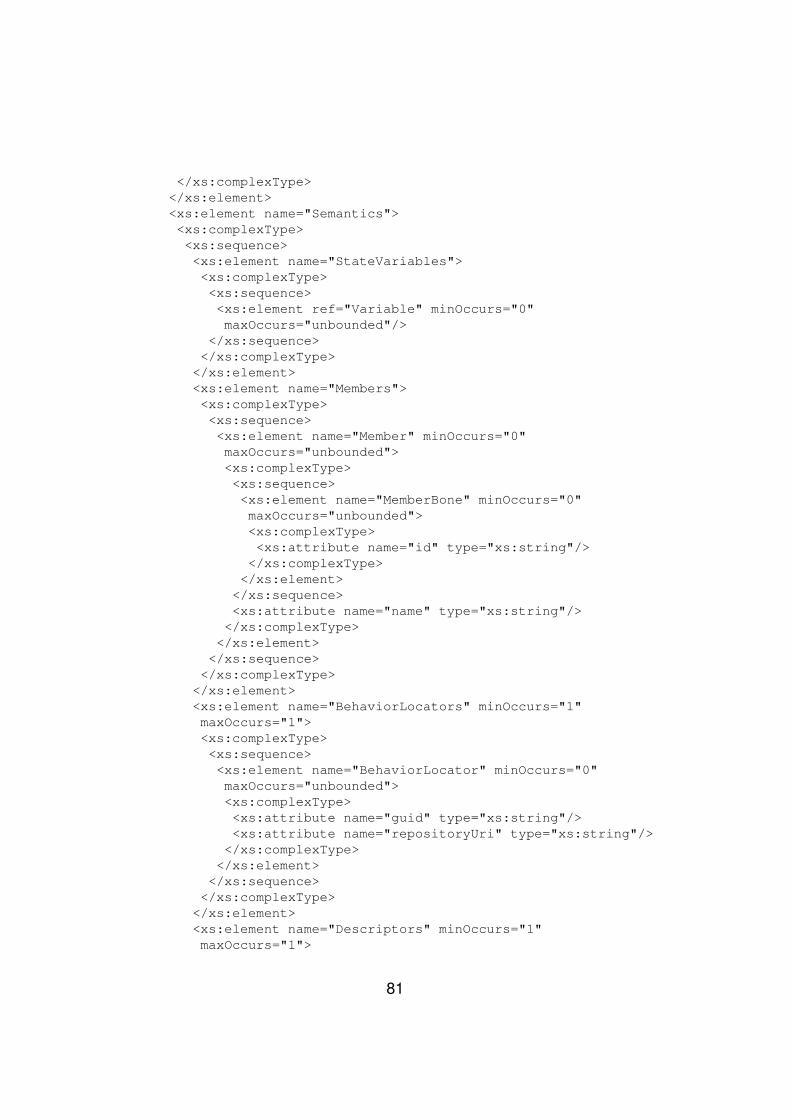
</xs:complexType></xs:element><xs:element name="Semantics"><xs:complexType><xs:sequence><xs:element name="StateVariables"><xs:complexType><xs:sequence><xs:element ref="Variable" minOccurs="0"maxOccurs="unbounded"/>
</xs:sequence></xs:complexType>
</xs:element><xs:element name="Members"><xs:complexType><xs:sequence><xs:element name="Member" minOccurs="0"maxOccurs="unbounded"><xs:complexType><xs:sequence><xs:element name="MemberBone" minOccurs="0"maxOccurs="unbounded"><xs:complexType><xs:attribute name="id" type="xs:string"/>
</xs:complexType></xs:element>
</xs:sequence><xs:attribute name="name" type="xs:string"/></xs:complexType>
</xs:element></xs:sequence></xs:complexType>
</xs:element><xs:element name="BehaviorLocators" minOccurs="1"maxOccurs="1"><xs:complexType><xs:sequence><xs:element name="BehaviorLocator" minOccurs="0"maxOccurs="unbounded"><xs:complexType><xs:attribute name="guid" type="xs:string"/><xs:attribute name="repositoryUri" type="xs:string"/></xs:complexType>
</xs:element></xs:sequence></xs:complexType>
</xs:element><xs:element name="Descriptors" minOccurs="1"maxOccurs="1">
81
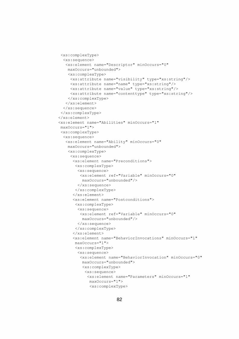
<xs:complexType><xs:sequence><xs:element name="Descriptor" minOccurs="0"maxOccurs="unbounded"><xs:complexType><xs:attribute name="visibility" type="xs:string"/><xs:attribute name="name" type="xs:string"/><xs:attribute name="value" type="xs:string"/><xs:attribute name="contenttype" type="xs:string"/></xs:complexType>
</xs:element></xs:sequence></xs:complexType>
</xs:element><xs:element name="Abilities" minOccurs="1"maxOccurs="1"><xs:complexType><xs:sequence><xs:element name="Ability" minOccurs="0"maxOccurs="unbounded"><xs:complexType><xs:sequence><xs:element name="Preconditions"><xs:complexType><xs:sequence><xs:element ref="Variable" minOccurs="0"maxOccurs="unbounded"/>
</xs:sequence></xs:complexType></xs:element><xs:element name="Postconditions"><xs:complexType><xs:sequence><xs:element ref="Variable" minOccurs="0"maxOccurs="unbounded"/>
</xs:sequence></xs:complexType></xs:element><xs:element name="BehaviorInvocations" minOccurs="1"maxOccurs="1"><xs:complexType><xs:sequence><xs:element name="BehaviorInvocation" minOccurs="0"maxOccurs="unbounded"><xs:complexType><xs:sequence><xs:element name="Parameters" minOccurs="1"maxOccurs="1"><xs:complexType>
82
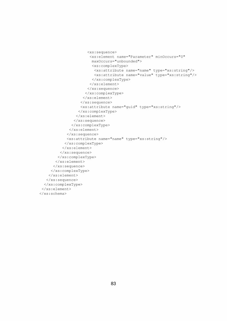
<xs:sequence><xs:element name="Parameter" minOccurs="0"maxOccurs="unbounded"><xs:complexType><xs:attribute name="name" type="xs:string"/><xs:attribute name="value" type="xs:string"/></xs:complexType>
</xs:element></xs:sequence></xs:complexType>
</xs:element></xs:sequence><xs:attribute name="guid" type="xs:string"/>
</xs:complexType></xs:element></xs:sequence>
</xs:complexType></xs:element>
</xs:sequence><xs:attribute name="name" type="xs:string"/></xs:complexType>
</xs:element></xs:sequence></xs:complexType>
</xs:element></xs:sequence>
</xs:complexType></xs:element></xs:sequence>
</xs:complexType></xs:element>
</xs:schema>
83
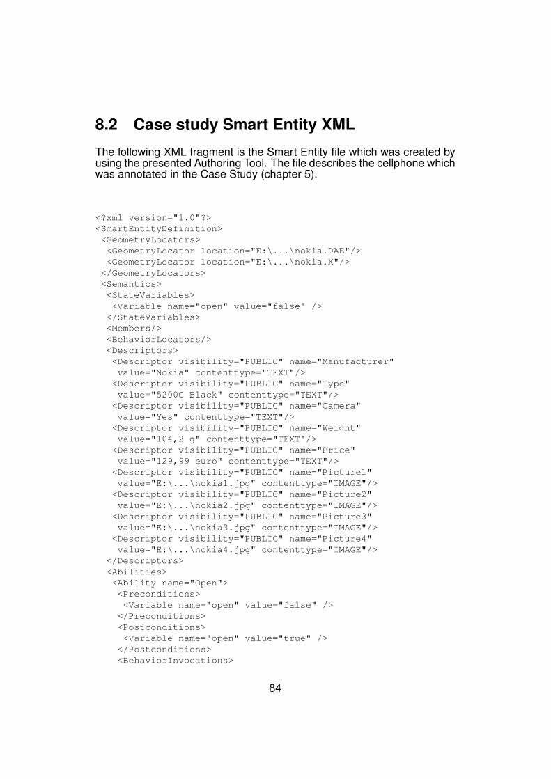
8.2 Case study Smart Entity XML
The following XML fragment is the Smart Entity file which was created byusing the presented Authoring Tool. The file describes the cellphone whichwas annotated in the Case Study (chapter 5).
<?xml version="1.0"?><SmartEntityDefinition><GeometryLocators><GeometryLocator location="E:\...\nokia.DAE"/><GeometryLocator location="E:\...\nokia.X"/></GeometryLocators><Semantics><StateVariables><Variable name="open" value="false" />
</StateVariables><Members/><BehaviorLocators/><Descriptors><Descriptor visibility="PUBLIC" name="Manufacturer"value="Nokia" contenttype="TEXT"/>
<Descriptor visibility="PUBLIC" name="Type"value="5200G Black" contenttype="TEXT"/>
<Descriptor visibility="PUBLIC" name="Camera"value="Yes" contenttype="TEXT"/>
<Descriptor visibility="PUBLIC" name="Weight"value="104,2 g" contenttype="TEXT"/>
<Descriptor visibility="PUBLIC" name="Price"value="129,99 euro" contenttype="TEXT"/>
<Descriptor visibility="PUBLIC" name="Picture1"value="E:\...\nokia1.jpg" contenttype="IMAGE"/>
<Descriptor visibility="PUBLIC" name="Picture2"value="E:\...\nokia2.jpg" contenttype="IMAGE"/>
<Descriptor visibility="PUBLIC" name="Picture3"value="E:\...\nokia3.jpg" contenttype="IMAGE"/>
<Descriptor visibility="PUBLIC" name="Picture4"value="E:\...\nokia4.jpg" contenttype="IMAGE"/>
</Descriptors><Abilities><Ability name="Open"><Preconditions><Variable name="open" value="false" /></Preconditions><Postconditions><Variable name="open" value="true" /></Postconditions><BehaviorInvocations>
84
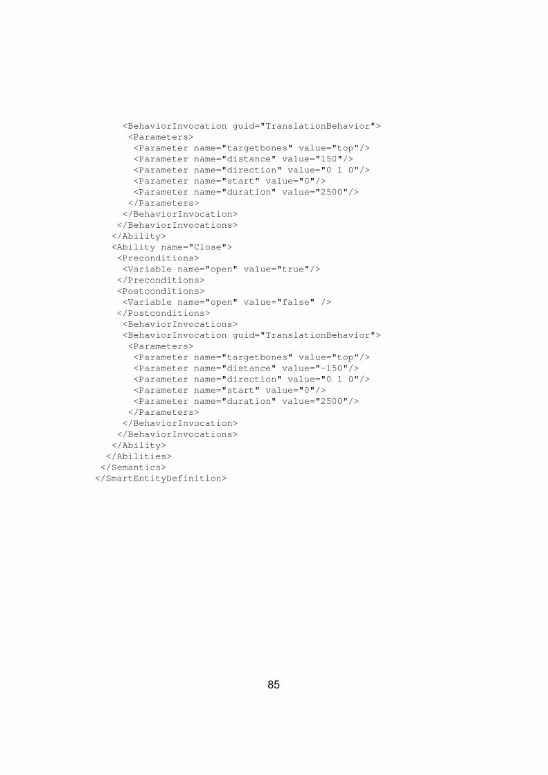
<BehaviorInvocation guid="TranslationBehavior"><Parameters><Parameter name="targetbones" value="top"/><Parameter name="distance" value="150"/><Parameter name="direction" value="0 1 0"/><Parameter name="start" value="0"/><Parameter name="duration" value="2500"/></Parameters>
</BehaviorInvocation></BehaviorInvocations>
</Ability><Ability name="Close"><Preconditions><Variable name="open" value="true"/></Preconditions><Postconditions><Variable name="open" value="false" /></Postconditions><BehaviorInvocations><BehaviorInvocation guid="TranslationBehavior"><Parameters><Parameter name="targetbones" value="top"/><Parameter name="distance" value="-150"/><Parameter name="direction" value="0 1 0"/><Parameter name="start" value="0"/><Parameter name="duration" value="2500"/></Parameters>
</BehaviorInvocation></BehaviorInvocations>
</Ability></Abilities></Semantics>
</SmartEntityDefinition>
85
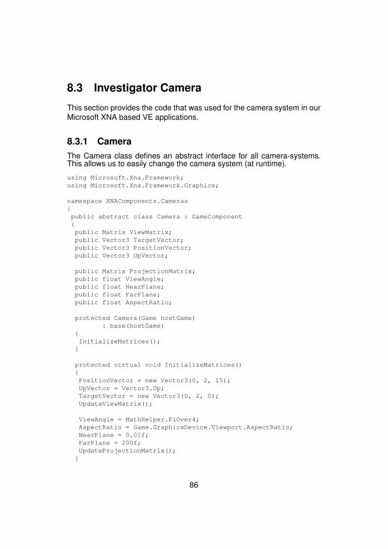
8.3 Investigator Camera
This section provides the code that was used for the camera system in ourMicrosoft XNA based VE applications.
8.3.1 CameraThe Camera class defines an abstract interface for all camera-systems.This allows us to easily change the camera system (at runtime).
using Microsoft.Xna.Framework;using Microsoft.Xna.Framework.Graphics;
namespace XNAComponents.Cameras{public abstract class Camera : GameComponent{public Matrix ViewMatrix;public Vector3 TargetVector;public Vector3 PositionVector;public Vector3 UpVector;
public Matrix ProjectionMatrix;public float ViewAngle;public float NearPlane;public float FarPlane;public float AspectRatio;
protected Camera(Game hostGame): base(hostGame)
{InitializeMatrices();
}
protected virtual void InitializeMatrices(){PositionVector = new Vector3(0, 2, 15);UpVector = Vector3.Up;TargetVector = new Vector3(0, 2, 0);UpdateViewMatrix();
ViewAngle = MathHelper.PiOver4;AspectRatio = Game.GraphicsDevice.Viewport.AspectRatio;NearPlane = 0.01f;FarPlane = 200f;UpdateProjectionMatrix();
}
86

public abstract void Up();public abstract void Down();public abstract void Left();public abstract void Right();public abstract void ZoomIn();public abstract void ZoomOut();
public virtual void UpdateViewMatrix(){ViewMatrix = Matrix.CreateLookAt(PositionVector, TargetVector,UpVector);
}
public virtual void UpdateProjectionMatrix(){ProjectionMatrix = Matrix.CreatePerspectiveFieldOfView(ViewAngle,AspectRatio, NearPlane, FarPlane);
}
public static Vector3 Unproject(Viewport viewport, Vector3 screenSpace,Matrix projection, Matrix view, Matrix world)
{//Convert the VE’s 3D coordinates to the screen’s 2D coordinates//First, convert raw screen coords to unprojectable ones
Vector3 position = new Vector3();position.X = (((screenSpace.X - (float)viewport.X)/ ((float)viewport.Width)) * 2f) - 1f;
position.Y = -((((screenSpace.Y - (float)viewport.Y)/ ((float)viewport.Height)) * 2f) - 1f);
position.Z = (screenSpace.Z - viewport.MinDepth)
/ (viewport.MaxDepth - viewport.MinDepth);
//Unproject by transforming the 4d vector by the//inverse of the projecttion matrix, followed by//the inverse of the view matrix.
Vector4 us4 = new Vector4(position, 1f);Vector4 up4 = Vector4.Transform(us4,Matrix.Invert(Matrix.Multiply(
Matrix.Multiply(world, view), projection)));Vector3 up3 = new Vector3(up4.X, up4.Y, up4.Z);return up3 / up4.W; //better to do this here to reduce precision loss
}}
}
87
8.3.2 InvestigatorCameraThe InvestigatorCamera allows circular rotation around an object in the VEaround the X- and Y-axes. Furthermore, users can zoom in and out. Thiscamera is used in the Authoring Tool.
using Microsoft.Xna.Framework;
namespace XNAComponents.Cameras{public class InvestigatorCamera : Camera{public float speed = MathHelper.ToRadians(1);private float zoomspeed = 0.5f;private float xRot = 0, yRot = 0;private Vector3 translationVector = Vector3.Zero;
public InvestigatorCamera(Game hostGame): base(hostGame)
{
}
public override void Update(GameTime gameTime){Quaternion qRot = Quaternion.Identity;
if ((PositionVector.Y <= 10) || (xRot < 0)){if ((PositionVector.Y >= -10) || (xRot > 0)){Vector3 perpendicularX = Vector3.Cross(
Vector3.Normalize(PositionVector),new Vector3(0, 1, 0));
qRot = Quaternion.CreateFromAxisAngle(perpendicularX, xRot);}}
PositionVector = Vector3.Transform(PositionVector,Matrix.CreateRotationY(yRot));PositionVector = Vector3.Transform(PositionVector,Matrix.CreateFromQuaternion(qRot));PositionVector = Vector3.Add(PositionVector,translationVector);
UpdateViewMatrix();UpdateProjectionMatrix();
xRot = 0;yRot = 0;
88
translationVector = Vector3.Zero;
base.Update(gameTime);}
public override void Up(){xRot += speed;
}
public override void Down(){xRot -= speed;
}
public override void Left(){yRot -= speed;
}
public override void Right(){yRot += speed;
}
public override void ZoomIn(){translationVector = Vector3.Add(translationVector,
Vector3.Multiply(Vector3.Normalize(PositionVector),zoomspeed));
}
public override void ZoomOut(){translationVector = Vector3.Add(translationVector,
Vector3.Multiply(Vector3.Normalize(PositionVector),-zoomspeed));
}}
}
89
8.4 TemplateBehavior
The TemplateBehavior class is an abstract interface which developers ofnew behavior implementations for our Smart Entity engine can use.
using Microsoft.Xna.Framework;using Microsoft.Xna.Framework.Graphics;using System.Diagnostics;using System.Collections.Generic;
namespace TemplateBehavior{public abstract class TemplateBehavior{private string _guid;private Game _hostGame;private Model _smartModel;private ModelBone[] _targetBones;private Matrix[] _originalBoneTransforms;private double _duration;private double _start;private double _position;
private Matrix _worldMatrix;private Matrix _viewMatrix;private Matrix _projectionMatrix;
protected TemplateBehavior(Game hostGame, Model smartModel){HostGame = hostGame;SmartModel = smartModel;
}
public abstract void Initialize();public abstract void Update(GameTime gameTime);
public void UpdateOriginalBoneTransforms(){if (SmartModel != null){OriginalBoneTransforms = new Matrix[SmartModel.Bones.Count];//COPY RELATIVE BONE TRANSFORMS!!!!!SmartModel.CopyBoneTransformsTo(OriginalBoneTransforms);
}}
90
public ModelBone[] TargetBones{get { return _targetBones; }set { _targetBones = value; }
}
public double Duration{get { return _duration; }set { _duration = value; }
}
public double Start{get { return _start; }set { _start = value; }
}
public Game HostGame{get { return _hostGame; }set { _hostGame = value; }
}
public Matrix WorldMatrix{get { return _worldMatrix; }set { _worldMatrix = value; }
}
public Matrix ViewMatrix{get { return _viewMatrix; }set { _viewMatrix = value; }
}
public Matrix ProjectionMatrix{get { return _projectionMatrix; }set { _projectionMatrix = value; }
}
91
public Model SmartModel{get { return _smartModel; }set { _smartModel = value; }
}
public Matrix[] OriginalBoneTransforms{get { return _originalBoneTransforms; }set { _originalBoneTransforms = value; }
}
public double Position{get { return _position; }set { _position = value; }
}
public string GUID{
get { return _guid; }set { _guid = value; }
}}
}
92
8.5 RotationBehaviorThe RotationBehavior class, inherits from the TemplateBehavior and im-plements a simple linear rotation around a given axis.
using System.Diagnostics;using Microsoft.Xna.Framework;using Microsoft.Xna.Framework.Graphics;using System.Collections.Generic;using System;
namespace RotationBehavior{public class RotationBehavior : TemplateBehavior.TemplateBehavior{private float _angle;private Vector3 _axis;
//The constructor should only take arguments that are//behavior INdependent and engine/platform dependent!public RotationBehavior(Game hostGame, Model smartModel)
: base(hostGame, smartModel){GUID = "RotationBehavior";Trace.WriteLine("External Behavior GUID = " + GUID);Trace.WriteLine("Invocation on = " + smartModel.Tag);}
public override void Update(GameTime gameTime){float absAngle = Math.Abs(Angle);
//Clamp will yield zero left of the interval//and angle right of the interval...float angle = MathHelper.Clamp((float)((Position - Start) / (Duration)) * absAngle, 0, absAngle);
Matrix rotationMatrix = Matrix.CreateFromAxisAngle(Axis,Math.Sign(Angle) * angle);
foreach (ModelBone aBone in TargetBones){aBone.Transform = rotationMatrix *OriginalBoneTransforms[aBone.Index];
}}
93
public float Angle{get { return _angle; }set { _angle = value; }}
public Vector3 Axis{get { return _axis; }set { _axis = value; }}
}}
94

8.6 TranslationBehaviorThe TranslationBehavior class can perform a linear translation behavior,given a direction (normalized vector) and a distance. The unit of this dis-tance depends on the coordinate system of the 3D model, so it is VE playerindependent.
using System;using System.Collections.Generic;using System.Linq;using Microsoft.Xna.Framework;
using System.Diagnostics;
namespace TranslationBehavior{public class TranslationBehavior : TemplateBehavior.TemplateBehavior{public Vector3 DirectionVector;public float DistanceMeasure;
public TranslationBehavior(Game hostGame, Model model): base(hostGame, model)
{}
public override void Update(GameTime gameTime){//Clamp will yield zero left of the interval//and angle right of the interval...float factor = MathHelper.Clamp((float)((Position - Start) / (Duration)), 0, 1);Vector3 transl = (factor * Distance) * Direction;
foreach (ModelBone aBone in TargetBones){aBone.Transform = Matrix.CreateTranslation(transl)
* OriginalBoneTransforms[aBone.Index];}
}
95
public Vector3 Direction{get { return DirectionVector; }set { DirectionVector = Vector3.Normalize(value); }
}
public float Distance{get { return DistanceMeasure; }set { DistanceMeasure = value; }
}}
}
96
