one company so many options maintenance … documents/maintenance and parts/parts...maintenance and...
TRANSCRIPT

MAINTENANCE AND ADJUSTMENT
MANUALFREIGHT DOORS • CAR GATES • RETIRING CAMS
WWW.COURIONDOORS.COM
ONE COMPANYSo Many Options

ver. 0220162(314) 533-5700 ● (800) 533-5760 ● [email protected] ● www.couriondoors.com
Regular and consistent maintenance of your COURION equipment will insure its proper and safe performance. Routinely examine, lubricate, clean, and adjust the equipment to ensure performance in accordance with COURION’s operating specifications and applicable Code requirements. Every time you are on site, you should visually inspect all COURION equipment to insure that it is operating properly, and that it is clean and free from damage. Above is the minimum routine maintenance guidelines for your COURION equipment. THESE ARE JUST GUIDELINES. More frequent maintenance may be necessary where doors are subject to high wear or corrosive effects of dust, abrasives, moisture, grease, chemicals, abnormal temperatures, or other conditions.
Maintenance Overview
This Manual details Courion’s recommended maintenance and adjustments for the mechanical portions of Courion’s Freight Elevator Doors, Car Gates, and Retiring Cam systems. For information concerning Courion’s Door and Gate Controller, and other electrical issues, please consult Courion’s Model MP Control Manual.
AVAILABLE FROM COURION
Since 1920, Courion has manufactured state-of-the-art equipment for its COURION and SECURITY Freight Door Systems, and CART-MATIC and TOTE-MATIC Dumb-waiter Systems. In addition, COURION is the exclusive provider of ENERGY, HAR-RIS PREBLE, and GUILBERT parts.
All replacement parts must be genuine COURION parts and, when required, bear a UL or CSA label. Failure to meet this requirement may void your COURION warranty and/or UL label.
If you have any questions regarding this Manual or need to order COURION, SECU-RITY, HARRIS PREBLE, or GUILBERT replacement parts, please contact COURI-ON’s Customer Service Department at (314) 533-5700 or (800) 533-5760.
Maintenance is the process of routine examination, lubrication, cleaning, adjustment, and replacement of parts for the purpose of ensuring performance in accordance with the manufacturers specifications and ap-plicable Code requirements. Where any alteration, replacement of parts, repair or maintenance is made, it should not diminish the level of safety which existed prior to the change.
COURION freight door and car gate equipment should receive the same maintenance as the balance of the elevator equipment. More frequent maintenance may be necessary where doors are subject to high wear or corrosive effects of dust, abrasives, moisture, grease, chemicals, abnormal temperatures, or other conditions.
At the back of this Manual is a chart entitled Routine Maintenance Guidelines that summarizes the informa-tion detailed in the following pages. This chart is meant to be used as a guideline. The actual condition of your specific hoistway, the amount of use the elevator receives, and the age of your COURION equipment should be used to determine the amount of maintenance necessary to properly maintain your COURION equipment.
What Is Maintenance?

3(314) 533-5700 ● (800) 533-5760 ● [email protected] ● www.couriondoors.com
Regular and consistent maintenance of your COURION equipment will insure its proper and safe performance. Routinely examine, lubricate, clean, and adjust the equipment to ensure performance in accordance with COURION’s operating specifications and applicable Code requirements. Every time you are on site, you should visually inspect all COURION equipment to insure that it is operating properly, and that it is clean and free from damage. Above is the minimum routine maintenance guidelines for your COURION equipment. THESE ARE JUST GUIDELINES. More frequent maintenance may be necessary where doors are subject to high wear or corrosive effects of dust, abrasives, moisture, grease, chemicals, abnormal temperatures, or other conditions.
COPYRIGHT AND DATA POLICY - COURION, the worldwide leading manufacturer of freight elevator doors, freight car enclosures, and the CART-MATIC and TOTE-MATIC automatic distribu-tion units, reserves all rights with respect to its registered copyrights on the materials presented in the Courion Maintenance and Adjustment Manual and Courion Product Data Compact Disk. Consequently, no part of this publication may be reproduced, copied or transmitted in any form or by any means -- including any information and storage retrieval system without prior written permission from COURION. Unlawful reproduction of the contents, imitation for commercial purposes or willful infringement of these copyrights will result in prosecution of the infringing party or parties under the copyright laws of the United States and the international treaties and conventions which apply. Inquiries concerning copyright information on the COURION Maintenance and Adjustment Manual and Product Data Compact Disk may be directed to COURION at 3044 Lambdin Avenue, St. Louis, Missouri 63115.
Door Panels ........................................................................................................................... 6Safety Meeting Rail (Safety Astragal) .................................................................................... 7Pull Straps (Web Straps) ....................................................................................................... 8Door Guide Rails ................................................................................................................... 9Door Stops........................................................................................................................... 10Door Guide Shoes (Door Gibs) ............................................................................................11Door Operators ............................................................................................................... 12-13Door Chains......................................................................................................................... 14Door Chain Rods ................................................................................................................. 15Interlocks ........................................................................................................................ 16-17Door iSENSOR .................................................................................................................... 18Door iDRIVE ........................................................................................................................ 19Door Limit Switches ............................................................................................................. 20Automatic Sta-Set Switch .................................................................................................... 21Emergency Unlocking Device (EUD)................................................................................... 22Gate Panels ......................................................................................................................... 24Gate Reversing Edge (Re-opening Device) ........................................................................ 25CARE Light Curtain (Non-Contact Re-opening Device) ...................................................... 26Car Gate Guides.................................................................................................................. 27Car Gate Drive Unit ........................................................................................................ 28-29Car Gate Chains ............................................................................................................. 30-31Geared Limit Switch ............................................................................................................ 32Gate iDRIVE.g ..................................................................................................................... 33Rotary Limit Switch .............................................................................................................. 34Gate Contact ....................................................................................................................... 35Retiring Cam................................................................................................................... 36-37Door Controls ................................................................................................................. 38-39
Table of Contents

ver. 0220164(314) 533-5700 ● (800) 533-5760 ● [email protected] ● www.couriondoors.com
Regular and consistent maintenance of your COURION equipment will insure its proper and safe performance. Routinely examine, lubricate, clean, and adjust the equipment to ensure performance in accordance with COURION’s operating specifications and applicable Code requirements. Every time you are on site, you should visually inspect all COURION equipment to insure that it is operating properly, and that it is clean and free from damage. Above is the minimum routine maintenance guidelines for your COURION equipment. THESE ARE JUST GUIDELINES. More frequent maintenance may be necessary where doors are subject to high wear or corrosive effects of dust, abrasives, moisture, grease, chemicals, abnormal temperatures, or other conditions.
PA-Style Door Layout
Part Description
Guide Rails
Door Operator
Limit Switch
Lock Bar & Lock Bar Guide
Chain & Chain Rod
Interlock
Guide Shoes
Guide Stops
Door Panels

5(314) 533-5700 ● (800) 533-5760 ● [email protected] ● www.couriondoors.com
Regular and consistent maintenance of your COURION equipment will insure its proper and safe performance. Routinely examine, lubricate, clean, and adjust the equipment to ensure performance in accordance with COURION’s operating specifications and applicable Code requirements. Every time you are on site, you should visually inspect all COURION equipment to insure that it is operating properly, and that it is clean and free from damage. Above is the minimum routine maintenance guidelines for your COURION equipment. THESE ARE JUST GUIDELINES. More frequent maintenance may be necessary where doors are subject to high wear or corrosive effects of dust, abrasives, moisture, grease, chemicals, abnormal temperatures, or other conditions.
Q-Style Door Layout
Part Description
Guide Rails
Door Operator
Limit Switch
Interlock
Open & Closed Cams
Chain & Chain Rod
Guide Stops
Guide Shoes
Door Panel
Auto Sta-Set Switch
ver. 0220166(314) 533-5700 ● (800) 533-5760 ● [email protected] ● www.couriondoors.com
Regular and consistent maintenance of your COURION equipment will insure its proper and safe performance. Routinely examine, lubricate, clean, and adjust the equipment to ensure performance in accordance with COURION’s operating specifications and applicable Code requirements. Every time you are on site, you should visually inspect all COURION equipment to insure that it is operating properly, and that it is clean and free from damage. Above is the minimum routine maintenance guidelines for your COURION equipment. THESE ARE JUST GUIDELINES. More frequent maintenance may be necessary where doors are subject to high wear or corrosive effects of dust, abrasives, moisture, grease, chemicals, abnormal temperatures, or other conditions.
Suggested Maintenance and Adjustment
Frequency
Door Equipment
Door Panels
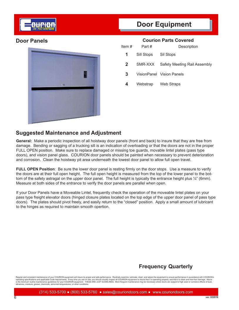
General: Make a periodic inspection of all hoistway door panels (front and back) to insure that they are free from damage. Bending or sagging of a trucking sill is an indication of overloading or that the doors are not in the proper FULL OPEN position. Make sure to replace damaged or missing toe guards, movable lintel plates (pass type doors), and vision panel glass. COURION door panels should be painted when necessary to prevent deterioration and corrosion. Clean the hoistway pit area underneath the lowest door panel to allow full open travel.
FULL OPEN Position: Be sure the lower door panel is resting firmly on the door stops. Use a measure to verify the doors are at their full open height. The full open height is measured from the top of the lower panel to the bot-tom of the safety astragal on the upper door panel. The full height is typically the entrance height plus ¼” (6mm). Measure at both sides of the entrance to verify the door panels are parallel when open.
If your Door Panels have a Moveable Lintel, frequently check the operation of the moveable lintel plates on your pass type freight elevator doors (hinged closure plates located on the top edge of the upper door panel of pass type doors). The plates should pivot freely, and easily return to the “closed” position. Apply a small amount of lubricant to the hinges as required to maintain smooth opertion.
Courion Parts CoveredItem # Part # Description
1 Sill Stops Sil Stops
2 SMR-XXX Safety Meeting Rail Assembly
3 VisionPanel Vision Panels
4 Webstrap Web Straps
Quarterly

7(314) 533-5700 ● (800) 533-5760 ● [email protected] ● www.couriondoors.com
Regular and consistent maintenance of your COURION equipment will insure its proper and safe performance. Routinely examine, lubricate, clean, and adjust the equipment to ensure performance in accordance with COURION’s operating specifications and applicable Code requirements. Every time you are on site, you should visually inspect all COURION equipment to insure that it is operating properly, and that it is clean and free from damage. Above is the minimum routine maintenance guidelines for your COURION equipment. THESE ARE JUST GUIDELINES. More frequent maintenance may be necessary where doors are subject to high wear or corrosive effects of dust, abrasives, moisture, grease, chemicals, abnormal temperatures, or other conditions.
Suggested Maintenance and Adjustment
Frequency
Door Equipment
Safety Meeting Rail (Safety Astragal)
The upper door panel has two bumpers and a safety astragal. The bumpers are located at each end of the safety meeting rail along the lower edge of the upper panel. These bumpers are vital to sustaining door performance and useful life. Rubber bumpers and the safety meeting rail will deteriorate. They should be periodically inspected and refastened or replaced as necessary. After any astragal replacement, check that the Safety Meeting Rail seals the gap between the upper and lower door panel in the full closed position.
Courion Parts CoveredItem # Part # Description
1 09-102201 Rubber Bumper
2 15-101000 Safety Meeting Rail Channel
3 15-101100 SMR Mounting Strip
4 20-005001 Novatex - 5”
5 20-005011 Novatex - 6”
6 90-855400 Novatex - 6” to 11”
Semi-Annual

ver. 0220168(314) 533-5700 ● (800) 533-5760 ● [email protected] ● www.couriondoors.com
Regular and consistent maintenance of your COURION equipment will insure its proper and safe performance. Routinely examine, lubricate, clean, and adjust the equipment to ensure performance in accordance with COURION’s operating specifications and applicable Code requirements. Every time you are on site, you should visually inspect all COURION equipment to insure that it is operating properly, and that it is clean and free from damage. Above is the minimum routine maintenance guidelines for your COURION equipment. THESE ARE JUST GUIDELINES. More frequent maintenance may be necessary where doors are subject to high wear or corrosive effects of dust, abrasives, moisture, grease, chemicals, abnormal temperatures, or other conditions.
Suggested Maintenance and Adjustment
Frequency
Door Equipment
Web Strap (Pull Strap)
Replace as necessary. Automatic elevators with manual doors require pull straps on the landing and hoistway sides of the upper door panel. Limit the length of the straps to ensure that they do not become a hazard during the opera-tion of the freight elevator car. In addition, the current ASME 17.1 Code requires that the bottom of the web strap be no more than 79” (200cm) above the floor when the Hoistway Doors are in the FULL OPEN position. The Web Strap may not be extended by other materials.
Courion Parts CoveredItem # Part # Description
1 09-800332 Web Strap - 32”
2 09-800356 Web Strap - 56”
3 09-800374 Web Strap - 74”
Semi-Annual

9(314) 533-5700 ● (800) 533-5760 ● [email protected] ● www.couriondoors.com
Regular and consistent maintenance of your COURION equipment will insure its proper and safe performance. Routinely examine, lubricate, clean, and adjust the equipment to ensure performance in accordance with COURION’s operating specifications and applicable Code requirements. Every time you are on site, you should visually inspect all COURION equipment to insure that it is operating properly, and that it is clean and free from damage. Above is the minimum routine maintenance guidelines for your COURION equipment. THESE ARE JUST GUIDELINES. More frequent maintenance may be necessary where doors are subject to high wear or corrosive effects of dust, abrasives, moisture, grease, chemicals, abnormal temperatures, or other conditions.
Suggested Maintenance and Adjustment
Frequency
Door Equipment
Door Guide Rails(Regular and Pass Type)
General: Clean and lubricate your door guide rails frequently. The exact frequency will depend on the particular environment of the hoistway and facility. At a minimum, door guides should be cleaned and lubricated on a monthly schedule. Using a clean cloth, wipe the door guides down to remove any dirt or residue. Rails with an accumula-tion of grease, oil, and dirt should be scrubbed clean with a degreaser and putty knife. Apply light weight oil (eleva-tor hydraulic oil or automotive #10 oil) to the guide rails. Lubricate rails with a dry lubricant in atmospheres contain-ing dust. DO NOT USE GREASE!
Make a periodic (at least annually) inspection of all guide rails to insure that they are straight and free from damage. Replace rails if necessary. At the same time, inspect the guide rail bolts and masonry anchors to be sure that they are tight.
Adjustment: The overall side-to-side play (left to right) of the door panel in the door guides should be limited to 1/8” (3mm). If the side-to-side play of any door panel exceeds this amount, you should adjust or replace the Door Guide Shoes if necessary (See Door Guide Shoes). If this does not eliminate the excessive side-to-side movement of your door panels, you will need to rehang the Door Guides in the correct location.
Courion Parts CoveredItem # Part # Description
1 Guide Lugs Guide Lugs
2 Guide Stop Guide Stops
Monthly

ver. 02201610(314) 533-5700 ● (800) 533-5760 ● [email protected] ● www.couriondoors.com
Regular and consistent maintenance of your COURION equipment will insure its proper and safe performance. Routinely examine, lubricate, clean, and adjust the equipment to ensure performance in accordance with COURION’s operating specifications and applicable Code requirements. Every time you are on site, you should visually inspect all COURION equipment to insure that it is operating properly, and that it is clean and free from damage. Above is the minimum routine maintenance guidelines for your COURION equipment. THESE ARE JUST GUIDELINES. More frequent maintenance may be necessary where doors are subject to high wear or corrosive effects of dust, abrasives, moisture, grease, chemicals, abnormal temperatures, or other conditions.
Suggested Maintenance and Adjustment
Frequency
Door Equipment
Door Guide Stops
General: Carefully clean and inspect the door stops (sill angle stops, adjustable guide stops, or both) for damage, distortion, and loose attachment. Correct any deficiencies immediately - Door Stops are important. The lower door panels must rest evenly on the door stops on both sides of the opening. When in the FULL OPEN position, the lower door panels should be level from side to side and 1/8” (3mm) below the sill.
Adjustment: Open the hoistway doors until the lower door panel is sitting firmly on the sill stop angles and/or guide stops. The upper edge of the lower door panel should be level from side to side and about 1/8” (3mm) below the building sill. Be sure to keep weight on top of the lower panel (stand on panel) when checking or making adjust-ments to the door panels to assure the panels remain in the FULL OPEN position.
If guide stops only are present, adjust the guide stops on both sides of the hoistway as necessary to obtain proper open position of the lower panel. If both sill stop angles and guide stops are present, adjust the guide stops on both sides of the hoistway so the head of the guide stop bolt is located 1/8” (3mm) below the lower door arms.
IMPORTANT: The guide stop bolt is not designed to support the trucking capacity of the freight door when sill stop angles are provided. The weight MUST be transmitted to the building through the sill stop angles. The guide stops serve only as a safety backup.
Courion Parts CoveredItem # Part # Description
Quarterly

11(314) 533-5700 ● (800) 533-5760 ● [email protected] ● www.couriondoors.com
Regular and consistent maintenance of your COURION equipment will insure its proper and safe performance. Routinely examine, lubricate, clean, and adjust the equipment to ensure performance in accordance with COURION’s operating specifications and applicable Code requirements. Every time you are on site, you should visually inspect all COURION equipment to insure that it is operating properly, and that it is clean and free from damage. Above is the minimum routine maintenance guidelines for your COURION equipment. THESE ARE JUST GUIDELINES. More frequent maintenance may be necessary where doors are subject to high wear or corrosive effects of dust, abrasives, moisture, grease, chemicals, abnormal temperatures, or other conditions.
Suggested Maintenance and Adjustment
Frequency
Door Equipment
Door Guide Shoes
General: Door Guide Shoes are extremely important. Frequently inspect all door guide shoes to ensure that they are free from damage and securely fastened to the door panels. Replace door guide shoes if overall side-to-side play (left to right) is greater than 1/8” (3mm), or do not allow free vertical movement of the freight door panels. Re-fasten or replace as necessary.
Adjustment: Adjust the door guide shoes inward or outward to maintain a 1/8” (3mm) overall side-to-side play (left to right) at both the top and bottom of each door panel. After adjustment, be sure the door does not bind in the guides and can be operated easily by hand. USE CAUTION WHEN TIGHTENING THE DOOR SHOES - EXCES-SIVE FORCE CAN STRIP THREADS IN THE DOOR PANEL SIDE ANGLE.
Courion Parts CoveredItem # Part # Description
1 09-829201 Guide Shoe Assembly - 292
2 09-829233 Guide Shoe Pack-292
3 09-829501 Guide Shoe Assembly - 295
4 09-829601 Guide Shoe Assembly - 296
5 09-829633 Guide Shoe Pack-296
6 09-870000 Guide Shoe Assebmly - LF96
7 09-870033 Guide Shoe Pack - LF96
Monthly

ver. 02201612(314) 533-5700 ● (800) 533-5760 ● [email protected] ● www.couriondoors.com
Regular and consistent maintenance of your COURION equipment will insure its proper and safe performance. Routinely examine, lubricate, clean, and adjust the equipment to ensure performance in accordance with COURION’s operating specifications and applicable Code requirements. Every time you are on site, you should visually inspect all COURION equipment to insure that it is operating properly, and that it is clean and free from damage. Above is the minimum routine maintenance guidelines for your COURION equipment. THESE ARE JUST GUIDELINES. More frequent maintenance may be necessary where doors are subject to high wear or corrosive effects of dust, abrasives, moisture, grease, chemicals, abnormal temperatures, or other conditions.
Suggested Maintenance and Adjustment
Frequency
Door Equipment
Door Operator - LP25
General: Make a periodic inspection of all door and gate operators to insure that they are clean and free from damage. Inspect the operator sheave to insure that the door or gate chains are running true and not causing any significant wear in the sheave. At the same time, inspect the mounting hardware to insure that it is tight.
Most COURION Operators and Manual Door Sheaves have grease-sealed ball bearings which do not require ad-ditional lubricant. Earlier installations have fittings for pressure gun lubrication. In those cases, grease the alemite fitting lightly at six month intervals using alemite lubricant. Do not over-grease.
COURION Operators allow for motor replacement without removing the sheave.
Q-Style: Disconnect the power source so that the motor leads are not “hot”. Remove the motor outlet box cover and disconnect the three (3) motor leads. Disconnect the conduit connection from the motor’s integral junction box. Remove the three (3) bolts attaching the motor to the operator. Firmly hold motor and pull motor down out of the operator housing. Make sure the motor mounting cavity and teeth on the sheave are free from dirt. Slide the new motor into the operator housing, making sure the motor spline meshes with the operator sheave gear teeth. Tighten the three (3) motor mounting bolts progressively and evenly. Each of the three (3) mounting bolts should be uniformly set “wrench” tight – DO NOT OVER-TIGHTEN the bolts. Re-connect the conduit and wiring. Check for proper rotation of the motor; if the motor rotation is incorrect, reverse the connection of any two of the three motor leads. Insulate the wiring connections and secure the cover to the junction box.
Courion Parts CoveredItem # Part # Description
1 02-250000 Door Operator - without motor
2 02-252001 Door Operator Sheave Gear
3 90-854000 LP25 Motor - 25 oz.
Quarterly

13(314) 533-5700 ● (800) 533-5760 ● [email protected] ● www.couriondoors.com
Regular and consistent maintenance of your COURION equipment will insure its proper and safe performance. Routinely examine, lubricate, clean, and adjust the equipment to ensure performance in accordance with COURION’s operating specifications and applicable Code requirements. Every time you are on site, you should visually inspect all COURION equipment to insure that it is operating properly, and that it is clean and free from damage. Above is the minimum routine maintenance guidelines for your COURION equipment. THESE ARE JUST GUIDELINES. More frequent maintenance may be necessary where doors are subject to high wear or corrosive effects of dust, abrasives, moisture, grease, chemicals, abnormal temperatures, or other conditions.
Suggested Maintenance and Adjustment
Frequency
Door Equipment
Door Operator - P Style
General: Make a periodic inspection of all door and gate operators to insure that they are clean and free from damage. Inspect the operator sheave to insure that the door or gate chains are running true and not causing any significant wear in the sheave. At the same time, inspect the mounting hardware to insure that it is tight.
Most COURION Operators and Manual Door Sheaves have grease-sealed ball bearings which do not require ad-ditional lubricant. Earlier installations have fittings for pressure gun lubrication. In those cases, grease the alemite fitting lightly at six month intervals using alemite lubricant. Do not over-grease.
PA-Style: Disconnect the power source so that motor leads are not “hot”. Remove the motor outlet box cover and disconnect the three (3) motor leads. Disconnect the conduit connection to the outlet box. Remove the four (4) bolts attaching the motor to the operator. Firmly grip the motor and pull motor out of the operator housing. Inspect the machined recess in the operator housing. The recess must be clean and undamaged. Slide the motor into the operator housing, making sure the motor face plate fits smoothly into the operator recess. Tighten the four (4) motor mounting bolts progressively and evenly to apply uniform pressure to the motor mounting collar. The motor is prop-erly installed when the machined collar on the motor plate is fully and evenly located within the operator housing recess. Each of the four (4) motor mounting bolts should now be uniformly set “wrench” tight. Do not over-tighten these bolts. The flanges on the motor mounting collar are not designed to pull flush with the operator housing. Re-connect the conduit and wiring and check for proper rotation of the motor. If motor rotation is incorrect, reverse the connection between any two of the three motor leads. Insulate the wiring connections and secure the cover to the outlet box.
Courion Parts CoveredItem # Part # Description
1 02-100309 Sheave Gear Assembly
2 02-198601 Door Operator - without motor
3 90-852600 Motor - 16 oz.
4 90-852800 Motor - 32 oz.
Quarterly

ver. 02201614(314) 533-5700 ● (800) 533-5760 ● [email protected] ● www.couriondoors.com
Regular and consistent maintenance of your COURION equipment will insure its proper and safe performance. Routinely examine, lubricate, clean, and adjust the equipment to ensure performance in accordance with COURION’s operating specifications and applicable Code requirements. Every time you are on site, you should visually inspect all COURION equipment to insure that it is operating properly, and that it is clean and free from damage. Above is the minimum routine maintenance guidelines for your COURION equipment. THESE ARE JUST GUIDELINES. More frequent maintenance may be necessary where doors are subject to high wear or corrosive effects of dust, abrasives, moisture, grease, chemicals, abnormal temperatures, or other conditions.
Suggested Maintenance and Adjustment
Frequency
Door Equipment
Hoistway Door Chain
General: Make a periodic inspection of all door chains to insure that they are not showing signs of wear. While some chain stretch is normal, replace chains if worn or stiff. Chain wear is exhibited as chain stretch. Most chain wear takes place on the interior surface of the chain pins as the chain leaf wears through the pins. This wear is not detectable by visual inspection of the chain. Be sure to replace any chains which exhibit a noticeable increase in pitch as compared with new chain. Links should move freely. At the same time you are inspecting the door chains, inspect the operator sheave to insure that the door chains are running free and true as the door panels open and close, and not causing any significant wear in the sheave.
Door Chains should be cleaned and lubricated at the same time you clean and lubricate the door guides. Lubricate the door chains frequently with light weight oil (elevator hydraulic oil or automotive #10 oil). To properly lubricate leaf chain, it is neces-sary for the oil to penetrate to the wearing surfaces of the chain (i.e., the chain pins). Surface lubrication is unnecessary and undesirable. Place a liberal quantity of lubricant on the chain at the pivots and allow the oil to penetrate the chain link. Wipe the surface of the chain to remove excess lubricant. DO NOT USE GREASE!
Q-Style: Any required chain length adjustment must be made at the upper door panel chain adjustment rod. DO NOT make chain length adjustment at the lower door panel chain rod. The chain adjustment rod nut is locked in position by either the Door Open Cam or a Chain Rod Adjustment Lock. Temporarily remove these devices to adjust the door chain length. Tighten the chain adjustment rod nut to increase full open height. If necessary, the door chains may be shortened by removing links at the connection to the lower door panel chain rod. Be sure to maintain weight on the lower panel when making and checking full open height adjustments. Replace the Door Open Cam or Chain Rod Adjustment Lock.
PA-Style: After some use, the door chains will wear and stretch out, allowing the center line of the two door panels to drop to a lower position. This will cause the locking bar to ride on top of the locking lug on the door lock, and prevent proper operation of the combination door lock and zone switch. The clearance between the top of the slot in the lock bar, and the top of the lock-ing lug, should be no more than a ¼”. Adjustments can be made by the lock nuts on the chain rods, under the lower door arm. When adjusted correctly, the upper and lower door panels will meet squarely.
Courion Parts CoveredItem # Part # Description
1 09-430670 Upper Panel Chain Rod & Chain - 69-3/8” Long
2 09-430682 Upper Panel Chain Bolt & Chain - 81” Long
Quarterly

15(314) 533-5700 ● (800) 533-5760 ● [email protected] ● www.couriondoors.com
Regular and consistent maintenance of your COURION equipment will insure its proper and safe performance. Routinely examine, lubricate, clean, and adjust the equipment to ensure performance in accordance with COURION’s operating specifications and applicable Code requirements. Every time you are on site, you should visually inspect all COURION equipment to insure that it is operating properly, and that it is clean and free from damage. Above is the minimum routine maintenance guidelines for your COURION equipment. THESE ARE JUST GUIDELINES. More frequent maintenance may be necessary where doors are subject to high wear or corrosive effects of dust, abrasives, moisture, grease, chemicals, abnormal temperatures, or other conditions.
Suggested Maintenance and Adjustment
Frequency
Door Equipment
Hoistway Door Chain Rods
General: Make a periodic (at least annually) inspection of all chain rods to insure that they are properly aligned, straight, and free from damage. At the same time, inspect all chain connections and mounting hardware to insure that they are secure and free from wear.
Adjustments
Q-Style: Close the freight doors and verify that the door panels are square and level. Check to see that the chain rods are approximately centered in the rod guides. Adjust the chain rod positioner, located under the door arm, to center and plumb the chain rod if necessary. Secure the chain rod positioner in place. With the interlock in the locked position, the door panels should not be able to open more than ¾” (19mm). The lower chain rod may be adjusted slightly to accomplish this.NOTE: Any adjustment to the lower chain rods must be compensated for by adjusting the door chain adjustment rod on the upper panel to maintain the door open height (e.g., if the lower chain rod hex nuts are loosened two turns, the upper door chain adjustment rod square nuts must be tightened two turns). Tighten the 5/8” (16mm) hex locknut on the lower end of the chain rod to secure in position.
PA-Style: Apply weight to the lower door panel to be sure that the door panels are in the FULL OPEN position and resting firmly on the guide or sill stops. Adjust the Hex Nuts at the bottom of the Chain Rod until the door panels are in the FULL OPEN position.
FULL OPEN Position: Be sure the lower door panel is resting firmly on the door stops. Use a measure to verify the doors are at their full open height. The full open height is measured from the top of the lower panel to the bottom of the safety astragal on the upper door panel. The full height is typically entrance height plus ¼” (6mm). Measure at both sides of the entrance to verify the door panels are parallel when open.
Courion Parts CoveredItem # Part # Description
1 09-440611 Chain Rod - 48”
2 09-440641 Chain Rod - 60”
3 09-460053 Chain Rod - 53-1/2”
4 09-460065 Chain Rod - 65-1/2”
5 09-460077 Chain Rod - 77-1/2”
Annually

ver. 02201616(314) 533-5700 ● (800) 533-5760 ● [email protected] ● www.couriondoors.com
Regular and consistent maintenance of your COURION equipment will insure its proper and safe performance. Routinely examine, lubricate, clean, and adjust the equipment to ensure performance in accordance with COURION’s operating specifications and applicable Code requirements. Every time you are on site, you should visually inspect all COURION equipment to insure that it is operating properly, and that it is clean and free from damage. Above is the minimum routine maintenance guidelines for your COURION equipment. THESE ARE JUST GUIDELINES. More frequent maintenance may be necessary where doors are subject to high wear or corrosive effects of dust, abrasives, moisture, grease, chemicals, abnormal temperatures, or other conditions.
Suggested Maintenance and Adjustment
Frequency
Door Equipment
Interlocks - Q Style
CAUTION! Wires from the interlock contact are connected to the elevator vertical lift control, and may therefore be charged even when the safety switch for the door control is off. TURN ALL POWER OFF BEFORE REMOVING THE COVER OF THE INTERLOCK AND PERFORMING ANY WORK ON THE INTERLOCK CONTACTS.
General: Frequently inspect the condition and operation of the Interlocks. Make sure that the Interlock and Retiring Cam are functioning properly, free from damage, and securely attached to the door guide rail or interlock mounting plate. With the Interlock in the locked position, the Door Panel should not be able to open more than ¾” (19mm). Insure that in order for the elevator to operate, all hoistway doors are closed and locked at each opening.
Frequently inspect the condition and operation of the Interlock contacts. Clean all exposed contacts in the Interlock. Very fine sandpaper may be used on very dirty or burned contacts. Wipe out the area between contact surfaces with a lint free cloth to avoid leaving dust, oil or lint behind. Replace contacts as required.
Adjustments:
Q-Style: Check to see that the Chain Rod is centered in the Interlock rod guides (if not, refer to the Door Chain Rod Adjustments). Carefully inspect the Door Closed Keeper for wear and proper actuation of the Door Closed Cam on the Door Interlock. The Door Closed Keeper actuates the butterfly cam follower on the Interlock when the COU-RION freight doors are fully closed. The retiring or stationary cam should open the interlock latch enough to allow the square portion of the chain rod to pass through the interlock, allowing the COURION freight doors to open. If it is necessary to adjust the interlock roller arm, loosen the 3/8” (10mm) bolt attaching the roller arm adjuster to the interlock latch. Turn the 5/16” (8mm) set screw on the roller arm adjuster until the interlock latch is open enough to allow the square portion of the chain rod to pass through the interlock. Tighten the 3/8” (10mm) roller arm adjuster mounting bolt securely.
Courion Parts CoveredItem # Part # Description
1 21-240000 QIP Interlock - Power
2 21-240300 QIM Interlock - Manual
3 21-240700 QLC Lock and Contact
Monthly
17(314) 533-5700 ● (800) 533-5760 ● [email protected] ● www.couriondoors.com
Regular and consistent maintenance of your COURION equipment will insure its proper and safe performance. Routinely examine, lubricate, clean, and adjust the equipment to ensure performance in accordance with COURION’s operating specifications and applicable Code requirements. Every time you are on site, you should visually inspect all COURION equipment to insure that it is operating properly, and that it is clean and free from damage. Above is the minimum routine maintenance guidelines for your COURION equipment. THESE ARE JUST GUIDELINES. More frequent maintenance may be necessary where doors are subject to high wear or corrosive effects of dust, abrasives, moisture, grease, chemicals, abnormal temperatures, or other conditions.
Suggested Maintenance and Adjustment
Frequency
Door Equipment
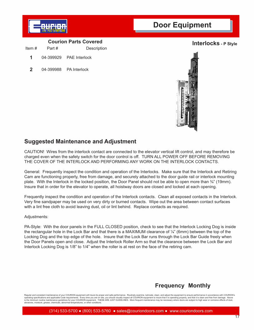
Interlocks - P Style
CAUTION! Wires from the interlock contact are connected to the elevator vertical lift control, and may therefore be charged even when the safety switch for the door control is off. TURN ALL POWER OFF BEFORE REMOVING THE COVER OF THE INTERLOCK AND PERFORMING ANY WORK ON THE INTERLOCK CONTACTS.
General: Frequently inspect the condition and operation of the Interlocks. Make sure that the Interlock and Retiring Cam are functioning properly, free from damage, and securely attached to the door guide rail or interlock mounting plate. With the Interlock in the locked position, the Door Panel should not be able to open more than ¾” (19mm). Insure that in order for the elevator to operate, all hoistway doors are closed and locked at each opening.
Frequently inspect the condition and operation of the Interlock contacts. Clean all exposed contacts in the Interlock. Very fine sandpaper may be used on very dirty or burned contacts. Wipe out the area between contact surfaces with a lint free cloth to avoid leaving dust, oil or lint behind. Replace contacts as required.
Adjustments:
PA-Style: With the door panels in the FULL CLOSED position, check to see that the Interlock Locking Dog is inside the rectangular hole in the Lock Bar and that there is a MAXIMUM clearance of ¼” (6mm) between the top of the Locking Dog and the top edge of the hole. Insure that the Lock Bar runs through the Lock Bar Guide freely when the Door Panels open and close. Adjust the Interlock Roller Arm so that the clearance between the Lock Bar and Interlock Locking Dog is 1/8” to 1/4” when the roller is at rest on the face of the retiring cam.
Courion Parts CoveredItem # Part # Description
1 04-399929 PAE Interlock
2 04-399988 PA Interlock
Monthly

ver. 02201618(314) 533-5700 ● (800) 533-5760 ● [email protected] ● www.couriondoors.com
Regular and consistent maintenance of your COURION equipment will insure its proper and safe performance. Routinely examine, lubricate, clean, and adjust the equipment to ensure performance in accordance with COURION’s operating specifications and applicable Code requirements. Every time you are on site, you should visually inspect all COURION equipment to insure that it is operating properly, and that it is clean and free from damage. Above is the minimum routine maintenance guidelines for your COURION equipment. THESE ARE JUST GUIDELINES. More frequent maintenance may be necessary where doors are subject to high wear or corrosive effects of dust, abrasives, moisture, grease, chemicals, abnormal temperatures, or other conditions.
Suggested Maintenance and Adjustment
Frequency
Door Equipment
Door iSENSORs - iLEARN Style
General: Frequently inspect the condition and operation of both the OPEN and CLOSE door iSENSORs. They should be free from damage, and securely attached to the lower door guide rail on the interlock side of the hoistway. Manually move the door panels - the led light on each iSENSOR should flicker as the magnet located on the lower door panel passes over each iSENSOR.
Inspect the iSENSOR magnet - it should be clean and free from damage. Replace the iSENSOR as required.
Adjustments:
There is a small notch on the top of the iSENSOR mounting bracket. Adjust the lower door panel (side-to-side) to make sure that the iSENSOR magnet on the lower door panel passes over the center of the notch. Using the iLEARN Control determine that both the OPEN and CLOSE door iSENSORs are reading 12” to 15” of the iSENSOR magnet during door operation. See the iLEARN System Manual for additional information.
Courion Parts CoveredItem # Part # Description
1 04-700000 iSENSOR KIt
2 04-700003 iSENSOR - Close
3 04-700004 iSENSOR - Open
4 90-717010 iSENSOR Magnet
Monthly

19(314) 533-5700 ● (800) 533-5760 ● [email protected] ● www.couriondoors.com
Regular and consistent maintenance of your COURION equipment will insure its proper and safe performance. Routinely examine, lubricate, clean, and adjust the equipment to ensure performance in accordance with COURION’s operating specifications and applicable Code requirements. Every time you are on site, you should visually inspect all COURION equipment to insure that it is operating properly, and that it is clean and free from damage. Above is the minimum routine maintenance guidelines for your COURION equipment. THESE ARE JUST GUIDELINES. More frequent maintenance may be necessary where doors are subject to high wear or corrosive effects of dust, abrasives, moisture, grease, chemicals, abnormal temperatures, or other conditions.
Suggested Maintenance and Adjustment
Frequency
Door Equipment
Door iDRIVE VFD Control - iLEARN
CAUTION! TURN ALL POWER OFF BEFORE REMOVING THE COVER OF THE iDRIVE VFD DOOR CONTROL AND PERFORMING ANY WORK ON THE VFD DRIVE UNIT.
General: Frequently inspect the condition and operation of the iDRIVE VFD Door Control. Make sure the cover is on and that it is securely attached to the hoistway wall or wiring trough.
Adjustments:
All adjustments to the iDRIVE VFD Door Control are made at the iLEARN Door Control. Please see the iLEARN System Manual for additional information.
Courion Parts CoveredItem # Part # Description
1 01-710000 iDRIVE VFD Door Control
Monthly

ver. 02201620(314) 533-5700 ● (800) 533-5760 ● [email protected] ● www.couriondoors.com
Regular and consistent maintenance of your COURION equipment will insure its proper and safe performance. Routinely examine, lubricate, clean, and adjust the equipment to ensure performance in accordance with COURION’s operating specifications and applicable Code requirements. Every time you are on site, you should visually inspect all COURION equipment to insure that it is operating properly, and that it is clean and free from damage. Above is the minimum routine maintenance guidelines for your COURION equipment. THESE ARE JUST GUIDELINES. More frequent maintenance may be necessary where doors are subject to high wear or corrosive effects of dust, abrasives, moisture, grease, chemicals, abnormal temperatures, or other conditions.
Suggested Maintenance and Adjustment
Frequency
Limit Switches
There are two types of door limit switches. Q-Style: The QLS limit switch contains both the DOOR OPEN and DOOR CLOSED contacts in a single switch located just under the Door Operator on the interlock side. PA-Style: The PA-Style limit switch (L) is a single contact switch used in pairs. One L Limit Switch is mounted above the inter-lock for use as the DOOR CLOSED contact, while the other type L Limit Switch is mounted below the interlock for use as the DOOR OPEN contact.
General: Frequently inspect the condition and operation of the Door Limit Switches and related Cams or Lock Bar. Make sure that the Limit Switches are functioning properly, free from damage, and securely attached to the door guide rail or interlock mounting plate. TURN POWER OFF BEFORE REMOVING THE COVER OF THE DOOR LIMIT SWITCHES AND PERFORMING ANY WORK ON THE LIMIT SWTICH CONTACTS. Frequently inspect the condition and operation of the limit switch contacts. Replace and clean as required.
Adjustments:
Q-Style: The QLS is actuated by OPEN and CLOSE cams attached to the bottom and top of the upper door panel. The positioning of these cams determines where the braking cycle begins. If the door slams open or closed without hesitating, move the appropriate cam towards the center of the opening. If the door hesitates or stops more than 2” (50mm) from the end of travel, move the appropriate cam away from the center of the opening.
PA-Style: Adjustment is made by changing the mounting location of the switch in the pre-punched series of mount-ing holes on the interlock mounting plate. The L Limit Switches are actuated by the lock bar attached to the lower door arm on the interlock side. Positioning of the type L Limit Switches determines where the braking cycle begins. If the door slams without hesitating, move the appropriate switch towards the center of the opening. If the door hesitates or stops more than 2” (50mm) from the end of travel, move the appropriate switch away from the center of the opening.
Courion Parts CoveredItem # Part # Description
1 04-250000 Limit Switch - Q Style
2 04-550001 Limit Switch - P Style
Monthly
Door Equipment

21(314) 533-5700 ● (800) 533-5760 ● [email protected] ● www.couriondoors.com
Regular and consistent maintenance of your COURION equipment will insure its proper and safe performance. Routinely examine, lubricate, clean, and adjust the equipment to ensure performance in accordance with COURION’s operating specifications and applicable Code requirements. Every time you are on site, you should visually inspect all COURION equipment to insure that it is operating properly, and that it is clean and free from damage. Above is the minimum routine maintenance guidelines for your COURION equipment. THESE ARE JUST GUIDELINES. More frequent maintenance may be necessary where doors are subject to high wear or corrosive effects of dust, abrasives, moisture, grease, chemicals, abnormal temperatures, or other conditions.
Suggested Maintenance and Adjustment
Frequency
Door Equipment
Auto-Sta Set Swtich
There are two types of Automatic Sta-Set switches. Q-Style: The Auto Sta-Set switch is mounted to the lower door panel guide stop and is actuated by a permanent cam on the lower door panel door arm. PA-Style: The PA-Style Auto Sta-Set switch is located on the top of the PA-Style Interlock and is actuated by the Lock Bar. When actuated, the Auto Sta-Set Switch energizes the door motors in the open direction and pulls the lower door panel back down into the FULL OPEN position. Actuation of the Auto Sta-Set Switch is usually caused when the lower door panel “bounces” during the loading and unloading of the freight elevator.
General: Frequently inspect the condition and operation of the Automatic Sta-Set Switches and related Cams. Make sure that the Auto-Sta Switches are functioning properly, free from damage, and securely attached to the door guide stops. TURN POWER OFF BEFORE REMOVING THE COVER OF THE AUTO STA-SET SWITCHES AND PERFORMING ANY WORK ON THE SWTICH CONTACTS. Frequently inspect the condition and operation of the switch contacts. Replace and or clean as required.
Adjustments:
Q-Style: The Auto Sta-Set Switch is actuated by a permanent cam attached to the lower door arm. Adjust the posi-tion of the switch by means of the slot in the Automatic Sta-Set Switch mounting bracket so the switch is actuated by the permanent cam when the lower door panel is ¼” to ¾” (6mm to 19mm) from FULL OPEN.
PA-Style: This device consists of a switch on each door which closes through movement of the lock bar about ¾” or more away from the sill during trucking operations. The closing of the switch energizes the open direction. The door will pull back down to the sill and open the Sta-Set switch. After the Sta-Set switch opens, the opening power will be held on the door for approximately another second and then the opening circuit will de-energize.
Courion Parts CoveredItem # Part # Description
1 04-589800 Auto-Sta Set Switch - P Style
2 21-260000 Auto-Sta Set Switch - Q Style
Semi-Annual

ver. 02201622(314) 533-5700 ● (800) 533-5760 ● [email protected] ● www.couriondoors.com
Regular and consistent maintenance of your COURION equipment will insure its proper and safe performance. Routinely examine, lubricate, clean, and adjust the equipment to ensure performance in accordance with COURION’s operating specifications and applicable Code requirements. Every time you are on site, you should visually inspect all COURION equipment to insure that it is operating properly, and that it is clean and free from damage. Above is the minimum routine maintenance guidelines for your COURION equipment. THESE ARE JUST GUIDELINES. More frequent maintenance may be necessary where doors are subject to high wear or corrosive effects of dust, abrasives, moisture, grease, chemicals, abnormal temperatures, or other conditions.
Suggested Maintenance and Adjustment
Frequency
Emergency Unlocking Devics - EUD
General: Frequently inspect the condition and operation of the Emergency Unlocking Device (EUD). Make sure that the EUDs are functioning properly, free from damage, and securely attached to the hallway wall. If an EUD is missing, it must be replaced. DO NOT LEAVE PULL CHAIN EXPOSED. TURN POWER OFF BEFORE REMOV-ING THE COVER OF THE EUDs AND PERFORMING ANY WORK ON THE EUD Switches. Frequently inspect the condition and operation of the switch contacts. Replace and/or clean as required.
OPERATION OF THE INTERLOCK BY THE EUD PULL CHAIN UNLOCKS THE HOISTWAY DOORS WHEN THE CAR IS NOT PRESENT AT THE LANDING. FOR THIS REASON, PLEASE KEEP THE EUD COVER LOCKED AND LIMIT ACCESS TO THE EUD KEYS.
Courion Parts CoveredItem # Part # Description
1 08-899504 EUD - Q Style
2 08-899505 EUD - P Style
Monthly
Door Equipment

23(314) 533-5700 ● (800) 533-5760 ● [email protected] ● www.couriondoors.com
Regular and consistent maintenance of your COURION equipment will insure its proper and safe performance. Routinely examine, lubricate, clean, and adjust the equipment to ensure performance in accordance with COURION’s operating specifications and applicable Code requirements. Every time you are on site, you should visually inspect all COURION equipment to insure that it is operating properly, and that it is clean and free from damage. Above is the minimum routine maintenance guidelines for your COURION equipment. THESE ARE JUST GUIDELINES. More frequent maintenance may be necessary where doors are subject to high wear or corrosive effects of dust, abrasives, moisture, grease, chemicals, abnormal temperatures, or other conditions.
Gate Equipment
Part Description
Gate Panels
Reversing Edge
CARE Light Curtain
Gate Guides
Gate Guide Shoes
Drive Unit & Cross Drive
Car Gate Chains
Geared Limit Switch
Rotary Limit Switch
Gate Contact

ver. 02201624(314) 533-5700 ● (800) 533-5760 ● [email protected] ● www.couriondoors.com
Regular and consistent maintenance of your COURION equipment will insure its proper and safe performance. Routinely examine, lubricate, clean, and adjust the equipment to ensure performance in accordance with COURION’s operating specifications and applicable Code requirements. Every time you are on site, you should visually inspect all COURION equipment to insure that it is operating properly, and that it is clean and free from damage. Above is the minimum routine maintenance guidelines for your COURION equipment. THESE ARE JUST GUIDELINES. More frequent maintenance may be necessary where doors are subject to high wear or corrosive effects of dust, abrasives, moisture, grease, chemicals, abnormal temperatures, or other conditions.
Suggested Maintenance and Adjustment
Frequency
Gate Panels
General: Make a periodic inspection of all Car Gate Panels (front and back) to insure that they are free from dam-age. Make sure to replace damaged or missing Reversing Edges and rubber bumpers. COURION Gate Panels should be painted when necessary to prevent deterioration and corrosion. The Car Gate Panel mesh must be able to reject a 2” (50mm) ball in a single-section gate, and 3/8” (10mm) ball in a multi-section gate.
Courion Parts CoveredItem # Part # Description
1 Rev Edge Gate Reversing Edge
2 09-800332 Web Strap - 32”
3 09-800356 Web Strap - 56”
4 09-800374 Web Strap - 74”
Quarterly
Gate Equipment

25(314) 533-5700 ● (800) 533-5760 ● [email protected] ● www.couriondoors.com
Regular and consistent maintenance of your COURION equipment will insure its proper and safe performance. Routinely examine, lubricate, clean, and adjust the equipment to ensure performance in accordance with COURION’s operating specifications and applicable Code requirements. Every time you are on site, you should visually inspect all COURION equipment to insure that it is operating properly, and that it is clean and free from damage. Above is the minimum routine maintenance guidelines for your COURION equipment. THESE ARE JUST GUIDELINES. More frequent maintenance may be necessary where doors are subject to high wear or corrosive effects of dust, abrasives, moisture, grease, chemicals, abnormal temperatures, or other conditions.
Suggested Maintenance and Adjustment
Frequency
Gate Equipment
Gate Reversing Edge
Gate Reversing Edge: The leading edge of a Car Gate is equipped with a Gate Reversing Edge. In the event that the gate lands on an obstruction in the closing direction, the Gate Reversing Edge causes the gate and hoistway doors to reverse direction and return to the FULL OPEN position.
Frequently check that the Gate Reversing Edge functions correctly when physical contact is made all along the re-versing edge. Replace the Reversing Edge and/or rubber bumper if damaged or if not fully operational. Check the reversing edge power-travel cable for wear; replace if any frayed conditions are obvious.
Courion Parts CoveredItem # Part # Description
1 07-600200 Contact Case Cover
2 07-600700 Insulator
3 07-689701 Trip Wire Spring
4 07-700025 SJO Cord Assembly - 3 Wire
5 07-990001 Swivel Reel Assembly
6 08-500300 Contact Lever Spring
7 09-102200 Rubber Bumper
Monthly
ver. 02201626(314) 533-5700 ● (800) 533-5760 ● [email protected] ● www.couriondoors.com
Regular and consistent maintenance of your COURION equipment will insure its proper and safe performance. Routinely examine, lubricate, clean, and adjust the equipment to ensure performance in accordance with COURION’s operating specifications and applicable Code requirements. Every time you are on site, you should visually inspect all COURION equipment to insure that it is operating properly, and that it is clean and free from damage. Above is the minimum routine maintenance guidelines for your COURION equipment. THESE ARE JUST GUIDELINES. More frequent maintenance may be necessary where doors are subject to high wear or corrosive effects of dust, abrasives, moisture, grease, chemicals, abnormal temperatures, or other conditions.
Suggested Maintenance and Adjustment
Frequency
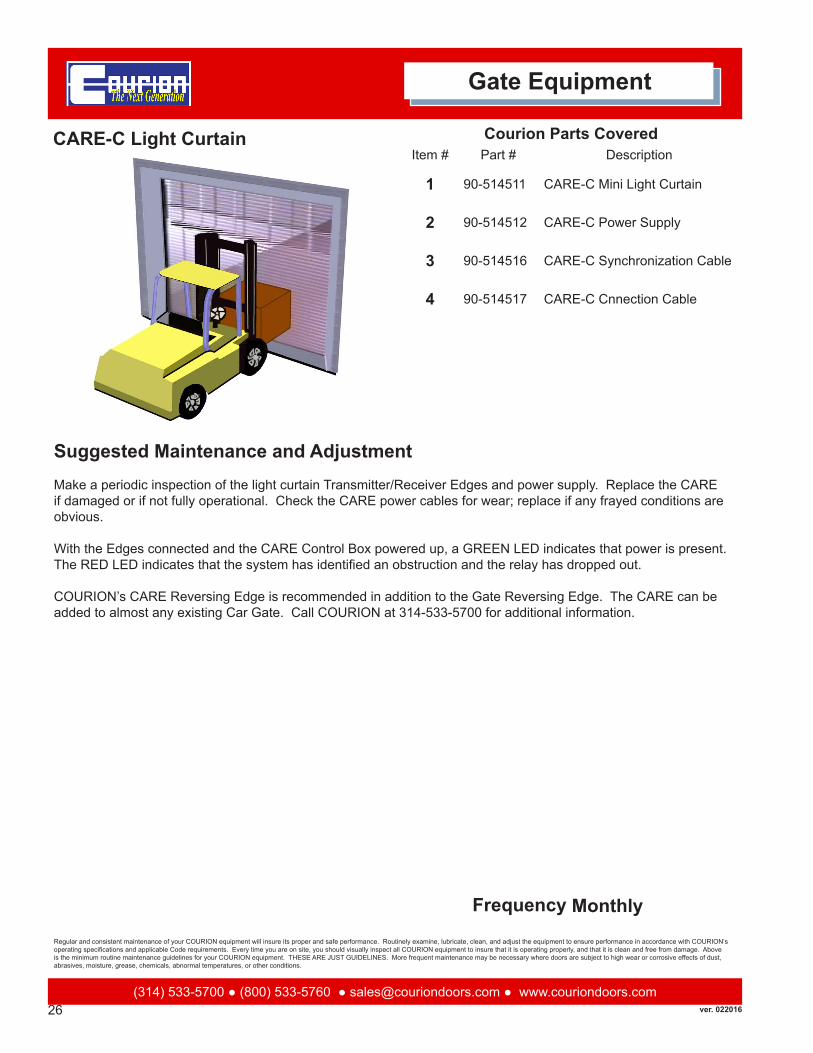
CARE-C Light Curtain
Make a periodic inspection of the light curtain Transmitter/Receiver Edges and power supply. Replace the CARE if damaged or if not fully operational. Check the CARE power cables for wear; replace if any frayed conditions are obvious.
With the Edges connected and the CARE Control Box powered up, a GREEN LED indicates that power is present. The RED LED indicates that the system has identified an obstruction and the relay has dropped out.
COURION’s CARE Reversing Edge is recommended in addition to the Gate Reversing Edge. The CARE can be added to almost any existing Car Gate. Call COURION at 314-533-5700 for additional information.
Courion Parts CoveredItem # Part # Description
1 90-514511 CARE-C Mini Light Curtain
2 90-514512 CARE-C Power Supply
3 90-514516 CARE-C Synchronization Cable
4 90-514517 CARE-C Cnnection Cable
Monthly
Gate Equipment

27(314) 533-5700 ● (800) 533-5760 ● [email protected] ● www.couriondoors.com
Regular and consistent maintenance of your COURION equipment will insure its proper and safe performance. Routinely examine, lubricate, clean, and adjust the equipment to ensure performance in accordance with COURION’s operating specifications and applicable Code requirements. Every time you are on site, you should visually inspect all COURION equipment to insure that it is operating properly, and that it is clean and free from damage. Above is the minimum routine maintenance guidelines for your COURION equipment. THESE ARE JUST GUIDELINES. More frequent maintenance may be necessary where doors are subject to high wear or corrosive effects of dust, abrasives, moisture, grease, chemicals, abnormal temperatures, or other conditions.
Suggested Maintenance and Adjustment
Frequency
Gate Equipment
Gate Guides and Counterweights
General: Clean and lubricate your car gate guide rails frequently. The exact frequency will depend on the particu-lar environment of the hoistway and facility. At a minimum, car gate guides should be cleaned and lubricated on a quarterly schedule. Using a clean cloth, wipe the car gate guides down to remove any dirt or residue. Rails with an accumulation of grease, oil, and dirt should be scrubbed clean with a degreaser and putty knife. Apply light weight oil (elevator hydraulic oil or automotive #10 oil) to the guide rails. Lubricate rails with a dry lubricant in atmospheres containing dust. DO NOT USE GREASE!
Make a periodic (at least annually) inspection of all guide rails to insure that they are straight and free from damage. Replace rails if necessary. At the same time, inspect the guide rail mounting bolts and guide rail supports to be sure that they are tight.
Adjustment: The overall side-to-side play (left to right) of the gate panel in the car gate guides should be limited to 1/8” (3mm). If the side-to-side play of any gate panel exceeds this amount, you should adjust or replace the Gate Guide Shoes (See Gate Guide Shoes). Operate the Gate Panel manually a few times to insure that it moves freely within the Car Gate Guides. Add or remove trim weights if needed.
Courion Parts CoveredItem # Part # Description
Quarterly

ver. 02201628(314) 533-5700 ● (800) 533-5760 ● [email protected] ● www.couriondoors.com
Regular and consistent maintenance of your COURION equipment will insure its proper and safe performance. Routinely examine, lubricate, clean, and adjust the equipment to ensure performance in accordance with COURION’s operating specifications and applicable Code requirements. Every time you are on site, you should visually inspect all COURION equipment to insure that it is operating properly, and that it is clean and free from damage. Above is the minimum routine maintenance guidelines for your COURION equipment. THESE ARE JUST GUIDELINES. More frequent maintenance may be necessary where doors are subject to high wear or corrosive effects of dust, abrasives, moisture, grease, chemicals, abnormal temperatures, or other conditions.
Suggested Maintenance and Adjustment
Frequency
Gate Drive Unit - Q Style
General: Make a periodic inspection of the Gate Drive Unit and Cross Drive Shaft to insure that they are operat-ing properly and clean and are free from damage. Inspect the drive unit’s sheave to insure that the gate chains are running true and not causing any significant wear in the sheave. At the same time, inspect the mounting hardware to insure that it is tight.
Most COURION Gate Sheaves have grease-sealed ball bearings which do not require additional lubricant. Earlier installations have fittings for pressure gun lubrication. In those cases, grease the alemite fitting lightly at six month intervals using alemite lubricant. Do not over-grease.
Cross Drive Shaft [Q Style Only]: Make sure that both Coupling Tubes at both ends of the Cross Drive Shaft have 1/8” (3mm) to ¼” (6mm) endplay at the Drive Pins. The Coupling Tubes MUST NOT BE LUBRICATED. However, a small amount of grease may be applied at each drive pin slot. If the Couplings operate in a hostile environment or are subject to an excess of falling dirt or debris, they may be covered with a thin wrap of rubber or other flexible material. This covering can be secured to the Coupling Tube with a hose clamp.
Adjustments:
Q-Style: Loosen the Drive Unit mounting bolts. Using the Belt Tension Adjuster, found on the underside of the Corner Bracket, adjust the Drive Unit for proper belt tension. Re-tighten the Drive Unit mounting bolts. Inspect the drive belt for wear and replace as needed.
WORN “V” BELTS MUST BE REPLACED PROMPTLY. CHECK “V” BELT TENSION BEFORE MAKING ADJUST-MENTS.
Courion Parts CoveredItem # Part # Description
1 21-750000 Q Gate Drive Unit - 32 oz.
2 90-809000 Timing Belt
3 90-853300 Motor - 32 oz.
Quarterly
Gate Equipment

29(314) 533-5700 ● (800) 533-5760 ● [email protected] ● www.couriondoors.com
Regular and consistent maintenance of your COURION equipment will insure its proper and safe performance. Routinely examine, lubricate, clean, and adjust the equipment to ensure performance in accordance with COURION’s operating specifications and applicable Code requirements. Every time you are on site, you should visually inspect all COURION equipment to insure that it is operating properly, and that it is clean and free from damage. Above is the minimum routine maintenance guidelines for your COURION equipment. THESE ARE JUST GUIDELINES. More frequent maintenance may be necessary where doors are subject to high wear or corrosive effects of dust, abrasives, moisture, grease, chemicals, abnormal temperatures, or other conditions.
Suggested Maintenance and Adjustment
Frequency
Gate Equipment
Gate Drive Unit - P Style
General: Make a periodic inspection of the Gate Drive Unit and Cross Drive Shaft to insure that they are operating properly and clean and are free from damage. Inspect the drive unit’s sheave to insure that the gate chains are run-ning true and not causing any significant wear in the sheave. At the same time, inspect the mounting hardware to insure that it is tight.
Most COURION Gate Sheaves have grease-sealed ball bearings which do not require additional lubricant. Earlier installations have fittings for pressure gun lubrication. In those cases, grease the alemite fitting lightly at six month intervals using alemite lubricant. Do not over-grease.
Adjustments:
PA-Style: The gate drive motor is mounted on a hinge plate to provide tension adjustment of the “V” belt. Adjust the motor hinge plate so that firm tension is maintained. Be certain that both nuts on the adjusting stud are locked tightly in place following adjustment.
WORN “V” BELTS MUST BE REPLACED PROMPTLY. CHECK “V” BELT TENSION BEFORE MAKING ADJUST-MENTS.
Courion Parts CoveredItem # Part # Description
1 07-228500 Gate Drive - 32 oz. Motor - Left Hand
2 07-228501 Gate Drive - 32 oz. Motor - Rhight Hand
3 07-228502 Gate Drive - 65 oz Motor - Left Hand
4 07-228503 Gate Drive - 65 oz Motor - Right Hand
5 90-809200 COG Belt
6 90-853300 Motor - 32 oz
7 90-853500 Motor - 65 oz
Quarterly

ver. 02201630(314) 533-5700 ● (800) 533-5760 ● [email protected] ● www.couriondoors.com
Regular and consistent maintenance of your COURION equipment will insure its proper and safe performance. Routinely examine, lubricate, clean, and adjust the equipment to ensure performance in accordance with COURION’s operating specifications and applicable Code requirements. Every time you are on site, you should visually inspect all COURION equipment to insure that it is operating properly, and that it is clean and free from damage. Above is the minimum routine maintenance guidelines for your COURION equipment. THESE ARE JUST GUIDELINES. More frequent maintenance may be necessary where doors are subject to high wear or corrosive effects of dust, abrasives, moisture, grease, chemicals, abnormal temperatures, or other conditions.
Suggested Maintenance and Adjustment
Frequency
Gate Chains & Chain Rods - Q Style
General: Make a periodic inspection of all gate chains to insure that they are not showing signs of wear. While some chain stretch is normal, replace chains if worn or stiff. Chain wear is exhibited as chain stretch. Most chain wear takes place on the interior surface of the chain pins as the chain leaf wears through the pins. This wear is not detectable by visual inspection of the chain. Be sure to replace any chains which exhibit a noticeable increase in pitch as compared with new chain. Links should move freely. At the same time you are inspecting the gate chains, inspect the operator sheave to insure that the gate chains are running free and true as the gate panels open and close, and are not causing any significant wear in the sheave. Gate Chains should be cleaned and lubricated at the same time you clean and lubricate the gate guides. Lubricate the gate chains frequently with light weight oil (eleva-tor hydraulic oil or automotive #10 oil). To properly lubricate leaf chain, it is necessary for the oil to penetrate to the wearing surfaces of the chain (i.e., the chain pins). Surface lubrication is unnecessary and undesirable. Place a liberal quantity of lubricant on the chain at the pivots and allow the oil to penetrate the chain link. Wipe the surface of the chain to remove excess lubricant. DO NOT USE GREASE! Adjustments:
Q-Style: As the suspension chains wear, they will exhibit elongation, and the top of the counterweight will no longer properly actuate the car gate contact. Adjustment is made with the car gate in the FULL CLOSED position. BLOCK THE GATE WEIGHT STACK BY INSERTING A BLOCKING WEDGE AT THE WEIGHT STACK CHAIN HITCH ON BOTH GATE COLUMNS. After the Gate is properly blocked, remove a chain link at the Gate Panel Chain Hitch. Adjust the Gate Panel on each Gate Mounting Plate so that the Gate Panel is in the FULL CLOSED position.
Courion Parts CoveredItem # Part # Description
1 90-819600 Chain - #40 Roller Chain
2 90-819700 Chain - #41 Roller Chain
Quarterly
Gate Equipment

31(314) 533-5700 ● (800) 533-5760 ● [email protected] ● www.couriondoors.com
Regular and consistent maintenance of your COURION equipment will insure its proper and safe performance. Routinely examine, lubricate, clean, and adjust the equipment to ensure performance in accordance with COURION’s operating specifications and applicable Code requirements. Every time you are on site, you should visually inspect all COURION equipment to insure that it is operating properly, and that it is clean and free from damage. Above is the minimum routine maintenance guidelines for your COURION equipment. THESE ARE JUST GUIDELINES. More frequent maintenance may be necessary where doors are subject to high wear or corrosive effects of dust, abrasives, moisture, grease, chemicals, abnormal temperatures, or other conditions.
Suggested Maintenance and Adjustment
Frequency
Gate Equipment
Gate Chain & Chain Rods - P Style
General: Make a periodic inspection of all gate chains to insure that they are not showing signs of wear. While some chain stretch is normal, replace chains if worn or stiff. Chain wear is exhibited as chain stretch. Most chain wear takes place on the interior surface of the chain pins as the chain leaf wears through the pins. This wear is not detectable by visual inspection of the chain. Be sure to replace any chains which exhibit a noticeable increase in pitch as compared with new chain. Links should move freely. At the same time you are inspecting the gate chains, inspect the operator sheave to insure that the gate chains are running free and true as the gate panels open and close, and are not causing any significant wear in the sheave. Gate Chains should be cleaned and lubricated at the same time you clean and lubricate the gate guides. Lubricate the gate chains frequently with light weight oil (eleva-tor hydraulic oil or automotive #10 oil). To properly lubricate leaf chain, it is necessary for the oil to penetrate to the wearing surfaces of the chain (i.e., the chain pins). Surface lubrication is unnecessary and undesirable. Place a liberal quantity of lubricant on the chain at the pivots and allow the oil to penetrate the chain link. Wipe the surface of the chain to remove excess lubricant. DO NOT USE GREASE!
Adjustments: PA-Style: Gate chains are connected to an equalizing bar at the top of the counterweight rod to automatically take care of difference in chain stretch. If your gate begins to operate sluggishly, and the guides are cleaned and oiled, chains probably need adjusting. To adjust chains, tighten gate chain bolt nuts on the LONG CHAIN side, (opposite the operator unit). Take up enough threads on the chain bolt to bring the long chain attach-ment point on the pivoting equalizer bar about two (2”) inches higher than the attachment point for the short chain. This allows the long chain to stretch about two (2) inches more than the short chain before further adjustment is necessary. As this adjustment is being made, push the gate down to contact the car floor so that the equalizing bar will swing to its proper position. After adjustments, pack the space between lock nut and cotter pin on the chain rod with washers to prevent the lock nuts from working loose. When further adjustment cannot be made at the chain bolt, one (1) or more sets of links can be removed from the end of the chain attached to the chain bolt. WHEN THE CHAIN MUST BE SHORTENED, WE SUGGEST THE CHAINS BE REPLACED, AS CONSIDERABLE WEAR WILL HAVE TAKEN PLACE AT THE BEARING SURFACES OF THE CHAIN LINKS AND PINS.
Courion Parts CoveredItem # Part # Description
1 07-108200 Compensating Chain
2 90-818800 Chain - #6 Cable Leaf
3 90-819600 Chain - #40 Roller Chain
4 90-819700 Chain - #41 Roller Chain
5 Combo Gate Combination Chain (#6 and #40)
Quarterly

ver. 02201632(314) 533-5700 ● (800) 533-5760 ● [email protected] ● www.couriondoors.com
Regular and consistent maintenance of your COURION equipment will insure its proper and safe performance. Routinely examine, lubricate, clean, and adjust the equipment to ensure performance in accordance with COURION’s operating specifications and applicable Code requirements. Every time you are on site, you should visually inspect all COURION equipment to insure that it is operating properly, and that it is clean and free from damage. Above is the minimum routine maintenance guidelines for your COURION equipment. THESE ARE JUST GUIDELINES. More frequent maintenance may be necessary where doors are subject to high wear or corrosive effects of dust, abrasives, moisture, grease, chemicals, abnormal temperatures, or other conditions.
Suggested Maintenance and Adjustment
Frequency
Geared Limit Switch - Q Style
General: Make a periodic inspection of the Geared Limit Switch to insure that it is clean and free from damage. At the same time, inspect the mounting hardware to insure that it is tight.
Freight Car Gate Adjustment: Slide the Geared Limit Switch back so that the gears do not engage the cross-drive shaft gear. Lift the Gate Panel to ½ of its open height. At the Geared Limit Switch, rotate the Cam Gear until the arrow points to the roller actuator of the limit switch. With the gears in this position, move the Geared Limit Switch forward to engage the Drive Gear on the cross-drive shaft. Tighten the Geared Limit Switch mounting bolts. Set the Geared Limit Switch Cams to actuate the limit switch when the Car Gate is about 13” (330mm) from FULL OPEN and FULL CLOSE. A properly adjusted Geared Limit Switch will cause the Car Gate to brake no more than 2” (50mm) from the final limit of travel in each direction.
Courion Parts CoveredItem # Part # Description
1 21-742000 Switch Cover
2 21-742500 Trans Gear
3 21-743000 Trans Gear
4 21-743500 Cam Gear
5 21-743700 Limit Switch Cam
6 90-983200 Microswitch
7 90-983250 Roller Arm
Monthly
Gate Equipment

33(314) 533-5700 ● (800) 533-5760 ● [email protected] ● www.couriondoors.com
Regular and consistent maintenance of your COURION equipment will insure its proper and safe performance. Routinely examine, lubricate, clean, and adjust the equipment to ensure performance in accordance with COURION’s operating specifications and applicable Code requirements. Every time you are on site, you should visually inspect all COURION equipment to insure that it is operating properly, and that it is clean and free from damage. Above is the minimum routine maintenance guidelines for your COURION equipment. THESE ARE JUST GUIDELINES. More frequent maintenance may be necessary where doors are subject to high wear or corrosive effects of dust, abrasives, moisture, grease, chemicals, abnormal temperatures, or other conditions.
Suggested Maintenance and Adjustment
Frequency
Gate Equipment
Gate iSENSOR.g - iLEARN
General: Frequently inspect the condition and operation of the Gate iSENSOR.g. It should be free from damage, and securely attached to the Car Gate cross angle. The drive chain should be secure over the sprocket. The en-coder coupler should be tight, free from damage, and cause the encoder spindle to turn as the gate panel moves up and down.
Adjustments:
Using the iLEARN Control determine that the encoder is providing sequential and consistant readings to the iL-EARN System. See the iLEARN System Manual for additional information.
Courion Parts CoveredItem # Part # Description
1 21-741004 Gate iSENSOR.g
2 90-713605 Flex Coupler
3 90-713700 iSENSOR.g Encodier
Monthly

ver. 02201634(314) 533-5700 ● (800) 533-5760 ● [email protected] ● www.couriondoors.com
Regular and consistent maintenance of your COURION equipment will insure its proper and safe performance. Routinely examine, lubricate, clean, and adjust the equipment to ensure performance in accordance with COURION’s operating specifications and applicable Code requirements. Every time you are on site, you should visually inspect all COURION equipment to insure that it is operating properly, and that it is clean and free from damage. Above is the minimum routine maintenance guidelines for your COURION equipment. THESE ARE JUST GUIDELINES. More frequent maintenance may be necessary where doors are subject to high wear or corrosive effects of dust, abrasives, moisture, grease, chemicals, abnormal temperatures, or other conditions.
Suggested Maintenance and Adjustment
Frequency
Gate Equipment
Rotary Limit Switch - Obsolete
General: Make a periodic inspection of the Gate Rotary Limit Switch to insure that it is clean and free from damage. At the same time, inspect the mounting hardware to insure that it is tight.
Lubricate the bearings, shaft, brass nuts, and roller chain on the rotary limit switch with a light machine oil. Avoid fouling the rotary limit switch contacts with excessive oil.
IF YOU HAVE A ROTARY LIMIT SWITCH AND ARE NOT HAPPY WITH ITS PERFORMANCE, YOU MAY RE-PLACE IT WITH COURION’S GEARED LIMIT SWITCH. PLEASE CONTACT COURION’S CUSTOMER SERVICE DEPARTMENT AT (800) 533-5760 OR (314) 533-5700 FOR MORE INFORMATION.
Adjustment: The Rotary Limit Switch is set by moving the location of the internal brass adjusting nuts along the shaft. Loosen the screws holding the Angle Guide in place and swing the guide clear of the brass nuts. Position each nut so that the corresponding limit switch opens when the gate is located approximately 13” (330mm) from FULL OPEN and FULL CLOSE. Tighten the Angle Guide back in place. A properly adjusted Rotary Limit Switch will allow the Car Gate to brake no more than 2” (50mm) from the final limit of travel in each direction.
Courion Parts CoveredItem # Part # Description
1 07-500302 Micro Switch Bracket
2 07-500400 Sprocket
3 07-500500 Collar
4 07-500700 Threaded Shaft
5 07-501100 Brass Nut
6 07-502000 Mounting Bracket
7 07-502100 Cover
Monthly

35(314) 533-5700 ● (800) 533-5760 ● [email protected] ● www.couriondoors.com
Regular and consistent maintenance of your COURION equipment will insure its proper and safe performance. Routinely examine, lubricate, clean, and adjust the equipment to ensure performance in accordance with COURION’s operating specifications and applicable Code requirements. Every time you are on site, you should visually inspect all COURION equipment to insure that it is operating properly, and that it is clean and free from damage. Above is the minimum routine maintenance guidelines for your COURION equipment. THESE ARE JUST GUIDELINES. More frequent maintenance may be necessary where doors are subject to high wear or corrosive effects of dust, abrasives, moisture, grease, chemicals, abnormal temperatures, or other conditions.
Suggested Maintenance and Adjustment
Frequency
Gate Equipment
Gate Contact
General: Make a periodic inspection of the Geared Limit Switch to insure that it is clean and free from damage. At the same The Gate Contact circuit should be closed only when the Car Gate is in the FULL CLOSED position. The Car Gate Closed circuit is intended for use with the lift control and does not interface with Courion’s door control.
General: Make a periodic inspection of the Gate Contact to insure that it is operating properly, and is clean and free from dam-age. At the same time, inspect the mounting hardware to insure that it is tight.
Adjustment: The Gate Contact is actuated by the top of the Gate Weight Stack. Check that the Gate Contact is properly actuat-ed when the Gate is in the FULL CLOSED position. All necessary adjustments are made to the Gate Chains [See Gate Chains].
Courion Parts CoveredItem # Part # Description
1 07-210000 Gate Contact - Q Style
2 07-489500 Gate Contact - Obsolete
Monthly

ver. 02201636(314) 533-5700 ● (800) 533-5760 ● [email protected] ● www.couriondoors.com
Regular and consistent maintenance of your COURION equipment will insure its proper and safe performance. Routinely examine, lubricate, clean, and adjust the equipment to ensure performance in accordance with COURION’s operating specifications and applicable Code requirements. Every time you are on site, you should visually inspect all COURION equipment to insure that it is operating properly, and that it is clean and free from damage. Above is the minimum routine maintenance guidelines for your COURION equipment. THESE ARE JUST GUIDELINES. More frequent maintenance may be necessary where doors are subject to high wear or corrosive effects of dust, abrasives, moisture, grease, chemicals, abnormal temperatures, or other conditions.
Suggested Maintenance and Adjustment
Frequency
Gate Contact
General: Make a periodic inspection of the Retiring Cam to insure that it is operating properly, and is clean and free from dam-age. At the same time, inspect the mounting hardware to insure that it is tight. Apply a light weight oil (elevator hydraulic oil or automotive #10 oil) to the pivot points on the cam and cam power unit and chain. Inspect the chain to insure that it is not show-ing any signs of wear. While some chain stretch is normal, replace chains if worn or stiff. Check the location of the Retiring Cam relative to the position of the Interlock Roller Arm to be sure that the Retiring Cam properly actuates the Interlock. [See Section on Interlock]. Also make sure that the Retiring Cam does not interfere with the Interlock Roller Arm as the car passes. When applicable, examine the air checks.
Adjustments:
If the Retiring Cam seems to be too noisy, or bounces too much when retiring or extending, check the following:
PA-Style: The Retiring Cam is adjusted with the air check located on the retiring cam power unit, and resistor R3 located at the top of the door control panel. To adjust the Retiring Cam unit, first make sure the chain from the power unit to the top of the cam is not slack. Using the Adjustment screw at the top of the Retiring Cam, adjust the screw until the Retiring Cam is at its most extended position with the Retiring Cam arms horizontal. Manually pick and drop the cam. Adjust the air check valve screw for the best operation of the cam. Turning the screw inward increases the checking, or backing the screw out decreases the checking. Too little checking will permit excessive slamming at the end of the stroke. Too much checking will cause excessive bouncing, as the pressure will build up too fast in the cylinder. There is an in-between point, which will give quiet operation, with a minimum amount of bouncing. BE SURE TO REPLACE THE LOCK NUT SECURELY ON THE ADJUSTING SCREW AFTER COMPLETING THE ADJUSTMENT.
Locate the Power Resistor in the upper right hand corner of the Courion Door Control cabinet. The Cam Power Unit is designed to work smoothly and quietly at or near the maximum resistance setting. Adjust the Cam Resistor until the cam picks smoothly. As the resistance is increased, the power developed by the motor is decreased.
Courion Parts CoveredItem # Part # Description
1 06-100000 Retiring Cam - P Style
Monthly
Retiring Cam

37(314) 533-5700 ● (800) 533-5760 ● [email protected] ● www.couriondoors.com
Regular and consistent maintenance of your COURION equipment will insure its proper and safe performance. Routinely examine, lubricate, clean, and adjust the equipment to ensure performance in accordance with COURION’s operating specifications and applicable Code requirements. Every time you are on site, you should visually inspect all COURION equipment to insure that it is operating properly, and that it is clean and free from damage. Above is the minimum routine maintenance guidelines for your COURION equipment. THESE ARE JUST GUIDELINES. More frequent maintenance may be necessary where doors are subject to high wear or corrosive effects of dust, abrasives, moisture, grease, chemicals, abnormal temperatures, or other conditions.
Suggested Maintenance and Adjustment
Frequency
Retiring Cam
Retiring Cam - Q Style
General: Make a periodic inspection of the Retiring Cam to insure that it is operating properly, and is clean and free from dam-age. At the same time, inspect the mounting hardware to insure that it is tight. Apply a light weight oil (elevator hydraulic oil or automotive #10 oil) to the pivot points on the cam and cam power unit and chain. Inspect the chain to insure that it is not show-ing any signs of wear. While some chain stretch is normal, replace chains if worn or stiff. Check the location of the Retiring Cam relative to the position of the Interlock Roller Arm to be sure that the Retiring Cam properly actuates the Interlock. [See Section on Interlock]. Also make sure that the Retiring Cam does not interfere with the Interlock Roller Arm as the car passes. When applicable, examine the air checks.
Adjustments:
If the Retiring Cam seems to be too noisy, or bounces too much when retiring or extending, check the following:
Q-Style: The Retiring Cam is adjusted with V-Belt tension on the retiring cam power unit, and resistor R3 located at the top of the door control panel. To adjust the Retiring Cam unit, first make sure the chain from the power unit to the top of the cam is not slack. Using the Adjustment screw at the top of the Retiring Cam, adjust the screw until the Retiring Cam is at its most extended position with the Retiring Cam arms horizontal. Manually pick and drop the cam, adjusting tension of the v-belt between the mo-tor and the cam pulley until the drop is smooth. The tension is increased by moving the motor mount away from the center.
Locate the Power Resistor in the upper right hand corner of the Courion Door Control cabinet. The Cam Power Unit is designed to work smoothly and quietly at or near the maximum resistance setting. Adjust the Cam Resistor until the cam picks smoothly. As the resistance is increased, the power developed by the motor is decreased.
Courion Parts CoveredItem # Part # Description
1 06-100000 Retiring Cam - Q Style
Monthly

ver. 02201638(314) 533-5700 ● (800) 533-5760 ● [email protected] ● www.couriondoors.com
Regular and consistent maintenance of your COURION equipment will insure its proper and safe performance. Routinely examine, lubricate, clean, and adjust the equipment to ensure performance in accordance with COURION’s operating specifications and applicable Code requirements. Every time you are on site, you should visually inspect all COURION equipment to insure that it is operating properly, and that it is clean and free from damage. Above is the minimum routine maintenance guidelines for your COURION equipment. THESE ARE JUST GUIDELINES. More frequent maintenance may be necessary where doors are subject to high wear or corrosive effects of dust, abrasives, moisture, grease, chemicals, abnormal temperatures, or other conditions.
Suggested Maintenance and Adjustment
Frequency
Door Control - iLEARN
See COURION’s iLEARN System Manual for a complete description of this door control.
Courion Parts CoveredItem # Part # Description
1 01-715000 iLEARN Door Control
2 01-710000 iDRIVE VFD Door Control
3 01-725000 iDRIVE VFD Gate Control
Monthly
Door Control

39(314) 533-5700 ● (800) 533-5760 ● [email protected] ● www.couriondoors.com
Regular and consistent maintenance of your COURION equipment will insure its proper and safe performance. Routinely examine, lubricate, clean, and adjust the equipment to ensure performance in accordance with COURION’s operating specifications and applicable Code requirements. Every time you are on site, you should visually inspect all COURION equipment to insure that it is operating properly, and that it is clean and free from damage. Above is the minimum routine maintenance guidelines for your COURION equipment. THESE ARE JUST GUIDELINES. More frequent maintenance may be necessary where doors are subject to high wear or corrosive effects of dust, abrasives, moisture, grease, chemicals, abnormal temperatures, or other conditions.
Suggested Maintenance and Adjustment
Frequency
Door Control - MP
See COURION’s MP Freight Door Control Installation and Adjustment Manual for a complete description of this door control.
Courion Parts CoveredItem # Part # Description
1 01-655000 MP Door Control
2 01-655100 MP Control Board
3 01-655200 MP Power Board
4 90-520001 Contactor - NC Aux
5 90-522000 Mechanical Interlock
6 90-551500 Microfuse
7 90-552000 Fuse - 1A
Monthly
Door Controller
