one year of jet-grouting in - matcon canada · jet-grouting is a well known soil improvement...
TRANSCRIPT

Two Years of Jet-Grouting in British Columbia
Case histories Paolo Gazzarrini P Eng- Sea To Sky Geotech Inc. – [email protected] – Ph. 604-913 1022 fax 604-913 0106 Mat Kokan P Eng – Geopacific Consultants – [email protected] –Ph. 604-439 0922 fax 604-439 9189 Steven Jungaro- Matcon Excavation and Shoring [email protected] ph. 604- 520 5909 fax 604- 520 5957
ABSTRACT Jet-Grouting is a well known soil improvement technique able to create in the subsoil consolidated elements with different shapes and dimensions with good mechanical characteristics and reduced permeability. The technique involves eroding the soil with cement grout jetted at high pressure (400 to 500 bars = 7,000 to 9,000 psi. Jet-Grouting was introduced in British Columbia in October 2004, and since then several applications have been carried out in the Lower Mainland. This paper will present several Jet-Grouting applications, specifically for: Underpinning, Shaft, Cut Off Wall, Shoring and Piling, in British Columbia. For each application, in addition to the geometry of the treatment, soil conditions and parameters used, the following data will be presented: UCS, Hydraulic conductivity and compression test evaluation, where applicable. In addition to the jet-grouting applications, the paper will briefly analyze the use of computers during the drilling phase to evaluate the soil characteristics. Torque, thrust, penetration rate and rotation are electronically monitored and recorded for the evaluation of the specific energy and for the evaluation of the soil conditions.
1) INTRODUCTION Since October 2004, the date of the first field test carried out on Mitchell Island, several Jet-grouting applications have been used in BC. Its use has solved interesting problems both from a technical, schedule and/or economical point of view. The versatility of the system, that involves the definition and optimization of several parameters, combined with the vibration-free and noise-free operations, has kept the system popular in BC’s market, up to now. This paper will describe the Jet-grouting works in which the authors have been directly involved, in addition with the analysis of the parameters used and results obtained. Paragraph 2 will describe briefly the location, geometry and soil condition of the jobs, and paragraph 3 will analyze the parameters and results. A special chapter will be reserved for the drilling parameters analysis. 2) APPLICATIONS, CASE HISTORIES ( in chronological order of execution) 2.1) MITCHELL ISLAND PRELIMINARY FIELD TEST (October 2004)
In September/October 2004 a preliminary test, was carried out on Mitchell Island, in Richmond, B.C. The test was intended to verify the technology in the local soil conditions. The test was divided into 2 stages. The initial stage included the installation of 8 scattered columns with varied jet grouting parameters to evaluate the most efficient result in terms of diameter and cement consumption. All the columns were excavated and some of them where extracted from the soil, where particularly good column characteristics where achieved. (see Photo 1 and 2). UCS and permeability tests were carried out on the best column. The second phase was carried out using the optimized parameters from phase 1 to create a semicircular wall in order to simulate the behavior of cut-off wall and the resulting impact on soil stability in cut. (See photo 3). The subsurface soils at the Mitchell Island site are typical over bank and fluvial deposits of the Fraser River Delta, with a superficial stratum of sandy to low plastic silt (approx 1.5m) over silty sand, with the water table, depending on the tide excursions, around 3 meters from the working platform

Photo 1- Excavated Column
Photo 2
Photo 3 2.2) PARCEL 5- NORTH VANCOUVER (March- May ’05) This Jet-Grouting application has previously been the subject of a paper presented in 2005 at the CGS
Symposium (Ref1), and will be not re-evaluated here. Only the data will be analyzed in paragraph 3 in comparison with the other results. This application of double Jet-Grouting was for a structural impervious temporary underpinning wall below the existing CN Rail tunnel. The jet Grouting was carried out in dense sand (Quadra Sand) with presence of local artesian water. 2.3) SHAFT – NORTH VANCOUVER (July ’05) The second application of Jet-Grouting in BC is related to the temporary stabilization of a small diameter shaft required for the construction of a 1,500 mm diameter vertical manhole for a storm line at the intersection of Esplanade and St. George Street in North Vancouver, and on the center lane of Esplanade. The shaft was 9.0 meters deep. A storm line was installed horizontally from the south side of the same CN tunnel discussed in 2.2 above and encountered significant construction difficulties due to the presence of “running sand” in the Quadra Formation. See Figure 1 with the section of the shaft and the original design.
Figure 1- Original Design (Substitute the Figure) The solution of soil improvement using jet-grouting was chosen due to time constraints (keeping Esplanade road closed for as short time as possible), miniminzing risk of project delays and avoiding excavation in stages as required for a conventional shoring solution (top down shoring installation shotcrete with dewatering). The designers were also encouraged by the success of the previous job. The Jet-Grouted shaft had a diameter of 3.7 meters. And a depth of 11.4 meters as shown on Figures 3, and 4. See Figure 2 with the proposed alternate. A total of 23 Jet Grouted (double system) columns were installed, 11.4 meters deep, around the circular
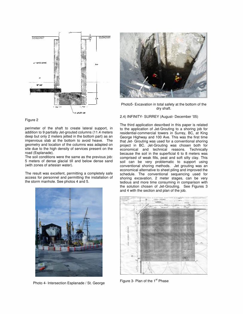
Figure 2 perimeter of the shaft to create lateral support, in addition to 9 partially Jet-grouted columns (11.4 meters deep but only 2 meters jetted in the bottom part) as an impervious slab at the bottom to avoid heave. The geometry and location of the columns was adapted on site due to the high density of services present on the road (Esplanade). The soil conditions were the same as the previous job: 5 meters of dense glacial till and below dense sand (with zones of artesian water). The result was excellent, permitting a completely safe access for personnel and permitting the installation of the storm manhole. See photos 4 and 5.
Photo 4- Intersection Esplanade / St. George
Photo5- Excavation in total safety at the bottom of the
dry shaft. 2.4) INFINITY- SURREY (August- December ’05) The third application described in this paper is related to the application of Jet-Grouting to a shoring job for residential-commercial towers in Surrey, BC, at King George Highway and 100 Ave. This was the first time that Jet- Grouting was used for a conventional shoring project in BC. Jet-Grouting was chosen both for economical and technical reasons. Technically because the soil in the superficial 6 to 8 meters was comprised of weak fills, peat and soft silty clay. This soil can be very problematic to support using conventional shoring methods. Jet grouting was an economical alternative to sheet piling and improved the schedule. The conventional sequencing used for shoring excavation, 2 meter stages, can be very tedious and more time consuming in comparison with the solution chosen of Jet-Grouting. See Figures 3 and 4 with the section and plan of the job.
Figure 3- Plan of the 1
st Phase

Figure 4 - Section A total of 345 Jet-Grouted columns were installed to a depth of 15 meters, using the double system. A steel H pile was installed at every second column to improve stiffness and provide bending and shear capacity. The soils characteristic of the site are from 0 to 6-8 meters (average) clay, from 6-8 m to the bottom of excavation, sand till with some silt and gravel. Considering that the soils present on site, clay and till, have totally different characteristics, it was not possible to use the same Jet-Grouting parameters for all of the columns. Different parameters were used: higher energy in till and lower energy in the silt to obtain the required diameters. See paragraph 3 and table 1 for the energy definition and evaluation, and paragraph 4 for the evaluation of the elevation in which the parameters have been varied. Photos 6 and 7, show the details of the Jet-Grouted wall and a cored sample in Till.
Photo 6 – Excavated Jet-Grouted, anchored wall
Photo 7 – Jet-Grouted cored sample in Till. 2.5) QUANTUM DEVELOPMENT – NEW WESTMINSTER (January –May ’06) The fourth case history of Jet-Grouting, here described, is related to a piling –structural application for a residential tower in New Westminster, BC. The foundations of the tower, as shown in Figure 5, are very close to the existing Sky Train tunnel. To avoid vibration and interference of the soil improvement treatment with the tunnel, Jet Grouting, vibration- free operation, was chosen as a piling/structural soil improvement solution. A total of 36 single Jet-Grouted piles, double system, 7.5 meters deep, were installed, in addition to foundation elements of different shapes, 7.5 to 15 meters deep, for a total of 305 Jet-grouted columns, as shown in Figure 5.
Figure 5 See the next paragraph for the compression test on Jet-Grouted Columns. The soils characteristic in the project are quite heterogeneous with, in principle, 0 to 6 meters of Fill, over 6 to 10 meters of Till over Sand.

3) SUMMARY OF THE DATA, ENERGETIC EVALUATION AND PRELIMINARY COMMENTS In table #1 the Jet-Grouting results obtained in 4 of the described jobs are summarized (in the shaft in North Vancouver no tests were carried out due to the same soil conditions of the previous job). In this table an energetic evaluation of Jet-Grouting is introduced. The Energetic Evaluation of Jet-Grouting has been the object of several papers by Mr. R. Tornaghi (Ref.2 is the most recent). The Specific Energy, function of the parameter used during Jet-grouting, is used both for design and evaluation of the results. The applied energy (Es) per unit length of column (Specific Energy) is calculated using the following formula, for the single Jet-grouting:
Q*p Es = -----------
vt where: Q= grout mix flow rate (m3/hr) P= grout mix pressure (MPa) vt= velocity of the withdraw of the rods (pulling back) during the jetting (m/hr) In the case of double or triple jet-grouting, the contribution of the air is evaluated as:
Esa= 0.35 * Qa [ (10* pa)
0.29 -1 ] / vt
With the data at our disposal, and analyzing the table, we can observe:
- The range of Energy used in the 4 jobs, varies from 13 to 49 MJ/meter; of course minor in the case of the single Jet-Grouting (13 MJ/m) up to 49 MJ/m in case of using double Jet-Grouting and high pressure/volume compressor.
- The value of Energy used is quite consistent in relationship to the diameters obtained and the type of soil. For instance the smaller amount of energy used in Mitchell Island test, produced diameters of columns of 600 to 900 mm and 49 MJ/m produced diameters in the order of 1,200 mm in case of the job in Quantum – New Westminster, even though the soils are slightly different.
- Also in terms of compressive strength, the results are very consistent. In clay the UCS was between 3 MPa and 4 MPa. In over bank silt the UCS was from 4 MPa to 5 MPa, and in fine to medium sand, between 10 MPa and 11 MPa. 18 MPa have been reached in the case of gravelly and cobbly soil.
- The hydraulic conductivity, in the tests carried out, also gave consistent results with interesting values in sand (highest content of cement) and over bank silt. The lowest values of hydraulic conductivity were detected in medium granular soil with lowest content of cement.
In terms of results, here below, we are analyzing the results obtained in a static compression test carried out in the Quantum-New Westminster Job. To verify the diameter of the columns and the capacity of the piles, a preliminary field test was carried out, with static compression test. Two (2) columns, as piles, with different parameters were Jet-Grouted, in addition to 3 Jet-Grouted reaction anchors to carry out 2 compression tests, after 28 days, as per sketch of Figure 6.
Figure 6 Photo 8 shows the head of the column, and photo 9 illustrates one of the compression test setups.
Photo 8: Pile #1, 1,200 mm diameter

Pile # 1 was tested, in a first attempt, up to 500 kips (2,225 kN). This test was suspended due to problems with the beam. The second attempt on the same pile reached 700 kips. See Figure 7 and 8 with the graphs of the results.. Pile # 2 was tested up the maximum load reachable from the beam, and it was suspended at 800 kips (3,560 kN). See Figure 9.
Photo 9- Compression test set-up
Figure 7- Jet-Grouted Pile tested at 500 kips – 1
st Test
Figure 8- Pile # 1 Tested at 700 kips.
Figure 9-. Pile # 2 tested at 800 kips After the permanent settlement of the pile, small elastic movement was noticed. Once the compression test was completed coring through the 2 columns was carried out, one in the center and the second 50 cm from the center. Photos 10, 11 and 12 show some details of the coring and results.
Photo 10: Log Box of pile #1
Photo 11: Detail of a Jet-Grouted sample with cobbles inclusion.

Photo 12: Jet-Grouted sample with the contact between a cored boulder, found 50 cm from the center of the column, and the jet-grouted soil. On some core samples, compression tests with evaluation of Young modulus and Poisson ratio, were carried out. See Table # 2 for the results. To install a barrier, as additional protection of the Sky Train tunnel, the General Contractor excavated a vertical trench. The excavation, 6.5 meters deep, provided the possibility of seeing the Jet-Grouted elements that appeared as a massive wall with excellent characteristics. The excavation didn’t require any support protection for the safety of the personnel. See photo 13 and 14 with the detail of the excavation.
Photo 13- Jet-Grouted Column on the left.
Photo 14 4) DRILING PARAMETERS REGISTRATION The Q/A, Q/C, computer controlled system with continuous registration of the parameters, used during the execution of Jet-Grouting allow for evaluation to all the jet-grouting parameters, as detailed in our previous paper (Ref1). The same computerized system is able to record also the drilling parameters as: advancement speed, rotation, torque and thrust. With these parameters it is possible to evaluate the specific energy used during drilling. Specific energy during drilling has already been object of papers (Ref.3) in the past, and can be evaluated with the following formula: e = F/A + 2*pi*R*T/A/v (KJ/m3) where: F= Thrust (kN) (force that is applied onto the drill rod) A= Area of the hole (m2) R= rotation (r per sec) T= Torque (kN*m) V= penetration rate (m/sec) Figure 10 shows the graph of the drilling parameters obtained, for example, in the Surrey-infinity job. In this job, as explained before, a change of the Jet-Grouting parameters was required to obtain the same diameter of columns in different soils. As we can see from the graph, the change of soil conditions is clearly visible at 6.5 meters. The advancement speed drops from approx. 400 cm/min to approx. 200 cm/min or less, the rpm and pressure drop and change , from constant values to very irregular. The torque, as opposite and logical, increases. This evaluation of the drilling graphs allowed the possibility of knowing very precisely the depth in which the change of Jet-Grouting parameters was required.

Figure 10- Drilling parameters report.
Figure 11 shows the same graph with the addition of the specific energy, correlated with the depth. The evaluation of the specific energy does not permit evaluation the characteristic of the soil but can provide an idea of the consistency of the soil and can be considered, in general terms, as an equivalent of the SPT. Tests and evaluation are still under development. 5) CONCLUSION After two (2) years of Jet-Grouting in British Columbia we can definitely affirm that the system was already entered locally into the field of common technologies used for soil improvement. The case histories described in this paper show only a few samples of the range of applicability of Jet-Grouting. The flexibility of the technology with the possibility of adapting the parameters to different soil conditions, drill through obstruction, in addition to vibration and noise-free operations, with no problem of headroom and the use of medium/small equipment have kept the technology popular. 6) ACKNOWLEDGEMENT We would like to thank Con-Tech System Inc and Obermann KG for the assistance in the preparation of the drilling parameter data, results and evaluation. References 1) P.Gazzarrini-M.Kokan-S.Jungaro, Case History of Jet-Grouting in BC- Underpinning of CN Rail Tunnel in North Vancouver- 58
th CGS Geotechnical Conference-
Geo-Sask 2005, Saskatoon, September18-21, 2005 2) R. Tornaghi- A. Pettinaroli. Design and Control Criteria of Jet-Grouting Treatments. ASEP-GI 2004, Paris 9-10 September 2004. Pages 295, 319 3) De Paoli-G.Viola-A.Tomiolo The Use of Drilling Energy For Soil Classification”. International Symposium, FMGM87, Kobe, Japan, April 6-9, 1987

T
ype o
f # o
f E
nerg
y
Dia
mete
r U
CS
P
erm
eabili
ty
Note
s
Job
Soil
(1)
Jet-
Gro
uting
colu
mns
(MJ/m
) of
colu
mns
#
test
Av
(Mpa)
Note
s
Test-
Mitchell
Isla
nd
0-2
m V
egeta
l S
oil
S
ingle
15
13.3
3
600 t
o 7
00m
m
2
4.9
5
5.6
and 4
.3 M
pa
8*1
0-8
Upper
colu
mn
2-
6 m
Silt
y S
and
800 t
o 9
00 m
m
2
11.2
5
10.7
and 1
1.8
Mpa
2*1
0-7
Bott
om
of
the c
olu
mn
Cubes s
am
ple
s p
repare
d f
rom
exc
avate
d c
olu
mn
P
arc
el 5 -
Nort
h
Vancouver
0-
3 T
ill
Double
231
38.9
6
1000
n/a
n/a
C
ylin
drical sam
ple
fro
m
7.6
*10
-8
3-
9 m
Quadra
Sand
n/a
1
14.8
coring
(
very
dense)
Shaft
- N
ort
h V
ancouver
0-5
m T
ill
Double
32
38.9
6
1000
No t
ests
5-
9.5
m Q
uadra
Sand
In
finity-
Surr
ey (
2
phases)
0-
6 (
avera
ge)
Cla
y
Double
345
20.3
0
900
5
3.8
6
Min
3 M
pa M
ax
4.9
Mpa
In c
lay
6-1
3.5
Till
2
7.4
0
n/a
2
10.5
9.4
and 1
1.6
Mpa
In
Till
Cylin
drical sam
ple
fro
m
coring
Q
uantu
m-
New
W
estm
inste
r 0-3
Fill
(avera
ge)
Double
300
48.6
1
1200
5
9.7
3
Min
5.1
6 M
ax
18.2
1 M
pa
Secant
Modulu
s 3
.35*1
03
3-1
0 T
ill (
avera
ge)
Cylin
drical sam
ple
fro
m
Pois
son r
atio=
0.2
6
10-1
2 S
and (
avera
ge)
coring
Note
s:
(1)
- 0=
work
ing p
latf
orm
. T
he f
inal depth
show
n is t
he f
inal depth
of
the jet-
gro
uting
TA
BL
E 1

T
ab
le 2
- Q
un
tum
– N
ew
We
stm
inste
r -U
CS
, S
eca
nt
mo
du
lus a
nd
Po
isso
n r
atio
re
su
lts