ons units 1,2 & 3 cyme-keowee program verification.' · cyme-keowee program verification...
TRANSCRIPT

ATTACHMENT 2

74 Hn4 -.- +02
Page 1
OCONEE NUCLEAR STATION UNITS 1,2 and 3
CYME-KEOWEE PROGRAM VERIFICATION
1i.0 SCOPE AND PURPOSE
The purpose of this calculation is to verify the validity of the Cyme induction motor model and the Keowee unit model. Because the Cymebase data base is used for other calculations, the data base may include components that are not relevant to this study. Since their presence in the data base does not affect the results of this study, they were not removed from the data base. If any of these extra components are used in future studies, the accuracy of their data must be verified.
2.0 REFERENCES
1. KM-301-3, Keowee Main Step Up Transformer Name Plate
2. OSC-4441 Rev. 01, Oconee Unit 1 ASDOP Input
3. OSC-4442 Rev. 01, Oconee Unit 2 ASDOP Input
4. OSC-4443 Rev. 01, Oconee Unit 3 ASDOP Input
3.0 ASSUMPTIONS
1. For the load rejection test, the Keowee generator voltage was not recorded and is assumed to be at nominal, 13.8 KV.
2. The voltage at the switchyard was at nominal, 230 KV.
4.0 CONCLUSION
The Keowee Cyme model and the adjusted parameters as shown in this calculation provide good correlations between the computer results and the test results. Therefore the model and the Cyme program are concluded to be valid for use in simulating the Keowee hydro unit supplying power to Oconee via the overhead path or the underground circult, from a steady state or a load rejection condition.
5.0 METHOD OF ANALYSIS
The validity of the Keowee Cyme-model is verified by using the model to simulate various tests and then compare the computer results with recorded test data. Various parameters of the models are adjusted until a good correlation between the Cyme results and test data is obtained.
By:st .2hs/oj kwcymvr0.doc Checked& o, jc OSC 5336Rev.00
9511270220 951117 PDR ADOCK 05000269 P PDR

2 Page 2
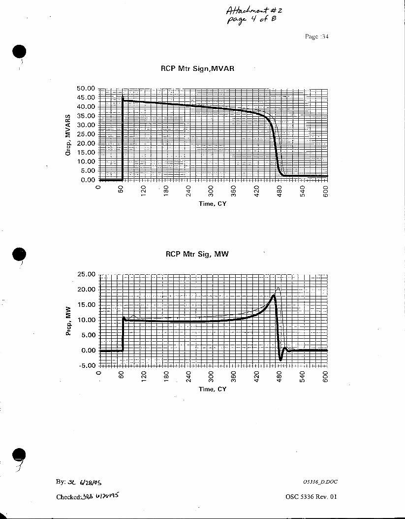
For the purpose of verifying the program, three tests were performed and relevant data recorded. The first test was a motor signature test of a reactor coolant pump motor; the second test was the Keowee-reactor coolant pump motor combination test, and the third test was a load rejection test. To prevent any RCP flow during the 0% power, the pump was disconnected from the RCP motor during any tests that involved the starting of the RCP motor.
The purpose of the motor signature test was to obtain the start and run characteristics of the motor independently from the transient state of the Keowee generator. With the aid of these characteristics, a simulation of this test was performed using the Cyme program to validate the RCP motor model. To accomplish this objective, the RCP motor was aligned to receive power from the 230 KV system. This portion of the calculation is covered in Section 6.0.
For the second test, the Keowee unit was isolated and aligned to supply power to the RCP motor via the overhead path. The responses of the Keowee unit to the starting and running condition of the RCP motor were recorded. With the aid of the recorded data, a simulation of this test was performed using the Cyme program to validate the Keowee unit model. A more accurate model of the Keowee unit was obtained by adjusting some of the manufacturer calculated parameters and constants until a good correlation between the simulation and the test results was obtained. Since the motor model was already verified in the motor signature test and simulation, only the Keowee model was adjusted. This portion of the calculation is covered in Section 7.0.
A third test was a load rejection test. For this test, one Keowee unit was supplying 93 MW of power to the grid and then the unit was isolated to simulate a 93 MW load rejection. The generator frequency response was recorded during this test. With the aid of the recorded data, a Cyme simulation of the test was performed to validate the Keowee model for use in a load rejection simulation. Adjustments were made to the Keowee model such that a good correlation between the Cyme simulation and the test data exists for both. the load application case ( second test ), and the load rejection case (third test ). This portion of the calculation is covered in Section 8.0.
Once a single Cyme model of the Keowee unit is adequately validated, it can be used to perform analyses for Keowee supplying Oconee via the overhead or underground path.*
The following Cyme program modules were used:
1. CYMBASE V'2.36 2. MOTORP V 2.06 3. CYMFLOW 4.70 4. CYMEDIT V 5.40 5. CYMSTAB / UDM V 5.70
By: sc s1151/q kwcynvrO.doc
Checked: o OSC 5336 Rev. 00

/}hk J,,_ # 2
ae Page :33
RCP Mtr Sign- lrcp,Amp
4500.00 .
4000.00 --__
3500.00 E
3000.00
2500.00
. 2000.00 - ---
1500.00 -Test
1000.00 ICyme 500.00 - -
0.00 0 0 0 0 0 0 o 0 0 0 0 0 0 0 0 0 0
<D N co I 0 D C. CD 0 0 - r- N C') C') tO (0
Time, CY
RCP Mtr Sign, 2TB Volts
7 00.00
7800.00
6400.00
6200.00
6000.00 6 0 0 0 0 0 0 0 0 0 00..... o 0 0 0 0 0 0 0 0 0 0 0 c4 c o 0 c N co 0 o
S '- N C') C') LO CD
Time, CY
By:sc CaIL8A7.! 05336 D.DOC Checked:J m as9As OSC 5336 Rev. 01
Pagc :34
RCP Mtr Sign,MVAR
50.00 45.00 40.00
m 35.00
< 30.00 2 25.00 ci 20.00 c 15.00
10.00 5.00 0.00 P
0 0 0 .0 0 0 0 0 0 0 0 o o C o o o 0 o o co 0
(N Cl) c) IL CD
Time, CY
RCP Mtr Sig, MW
25.00
20.00
15.00
. 10.00
0. 5.00
0.00
-5.00 0 0 0 0 0 0 0 0 0 0 0
o N 0 0 0 0 00I 0 * - - . 1 MN C CO C C
Time, CY
By: - 6/2g 05336_D.DOC
Checked&94R1 (0 OSC 5336 Rev. 01
m

Pg, MW Feq, pu
o mn oa a 0 n 0 c 0 -o 0n
-1 0 60
60 120 180 240
120 300 --- -D 360 CD
180 0 420 C 480 CD
CDD 540
240 0 600 I Hil I660
3 CD 70C C720
30780
o b 840
.- 3< 900 36003 17-C) 960 -CD
1020 -% CD
420 1080 -1140 - -1200
480 1260 0 1320
1380 5401440
1500
600 1560 1620

Pagc :36
Keowee-RCP, Test/Cyme Vf
3
2.5
-1.5
1
0.5
0. . .. . . 0 00 0 0 0 0 0 0 0 0
CD N co 0 (D N co D 0 N CfD CD) LO (D
lime, CY
Keowee-RCP, Test/Cyme Ircp
07 7
6
5
2
0 0 0 0 0 0 0 0 0 0 (0 N CC) I 0 (0 Nl CC)D 0
04N CD ) C L CD
lime, CY - Ibase=638A
By cU / 05336 -D.DOC
Checked:J a 0 ' -' OSC 5336 Rev. 01

74
Page :37
Kw-RCP, Test/Cyme Vg&Vb
1.1
1.05
0. 0.95
> 0.9
a 0.85
0.8
0.75
0.7 o 0 0 0 0 0 0 0 0 0 0
O N CO It 0 Dto N CC I 0 -- r-- N C') C' t 4t LO CO
Time, CY
By: G,/ze/ - 05336 DDOC
Checked:J4 .' OSC 5336 Rev. 01

Gp, pu RPM, pu
00 0~ 0~ 0 0 0) 0 ---J
000o0 000 0 00 00 00 0000000 0 00 0 00 00 0 0 0 0 0 00
0 .0 - . . . .. .. .. .
2.5 ItIl2.51 1
5.0 T5.0
7.5 7.5
10.0 10.0
12.5 12.5
15.0 15j.0 .
17.5 ~17.5
S20.0 p20.0
RD 22.5 CD 2.5
25.0 25.0
27.5 27.5
30.0 30.0
32.5 32.5
35.0 35.0 --
373 37.5
40.0 407.0
cooco co c oooc

ATTACHMENT 3
S

Oconee Nuclear 1, 2 and 3 Page: 4 OSC-3290, Rev. 3 By: _& ftf7/6f
Chkd:S C. 5//qI'
APPENDIX A CYME Simulation of Field Tests
A-i. GENERAL
In order to certify/validate the CYME program, a series of four tests were performed with the grid or combustion turbine supplying the load. These tests are as follows:
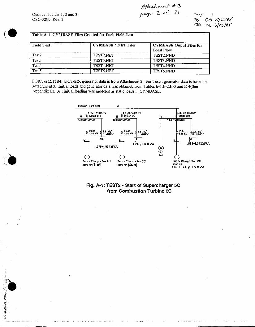
Test2: Start of Supercharger Fan 5C from Combustion Turbine 6C
For this test, Combustion Turbine 6C was running isolated from the grid but was connected to the other combustion turbine units as illustrated in Figure A-1. The supercharger fan on Unit 6C was initially running supplied from Unit 6C and the auxiliaries of Units 4C and 5C were also supplied from Unit 6C. Supercharger fan 5C was then started. Once supercharger fan 5C was up to speed, supercharger fan 4C was started. After both fans were running at steady state, supercharger fans 4C and 5C were tripped simultaneously. In modeling this test, only the start of supercharger fan 5C was modeled because once supercharger fan 5C was started, the running load was not stable resulting in a situation which could not be modeled accurately.
Test3: Start of Supercharger Fan 5C from the grid
For this test, all combustion turbines were shutdown with their auxiliaries supplied from the grid. Supercharger 5C on Unit 5C was then started.
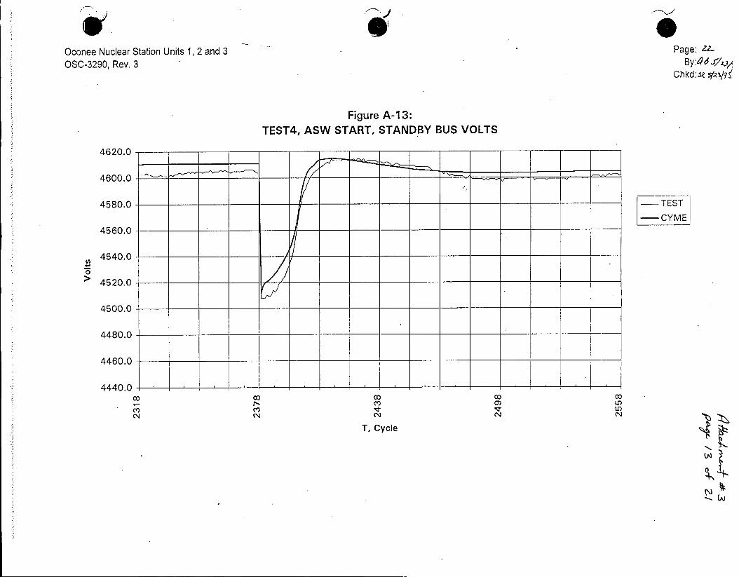
Test4: Start of ASW Pump at Oconee from Combustion Turbine 6C
For this test, Combustion Turbine 6C was running isolated from the grid but connected to the Oconee Standby Bus. Unit 6C was supplying its own auxiliaries and Supercharger 6C as well as the charging load for the circuit to Oconee. No loads were initially connected to the standby bus at Oconee. The ASW pump was then started from the standby bus. All electrical parameters(voltage, amperes, power, etc.) for the ASW pump was monitored at the Standby Bus.
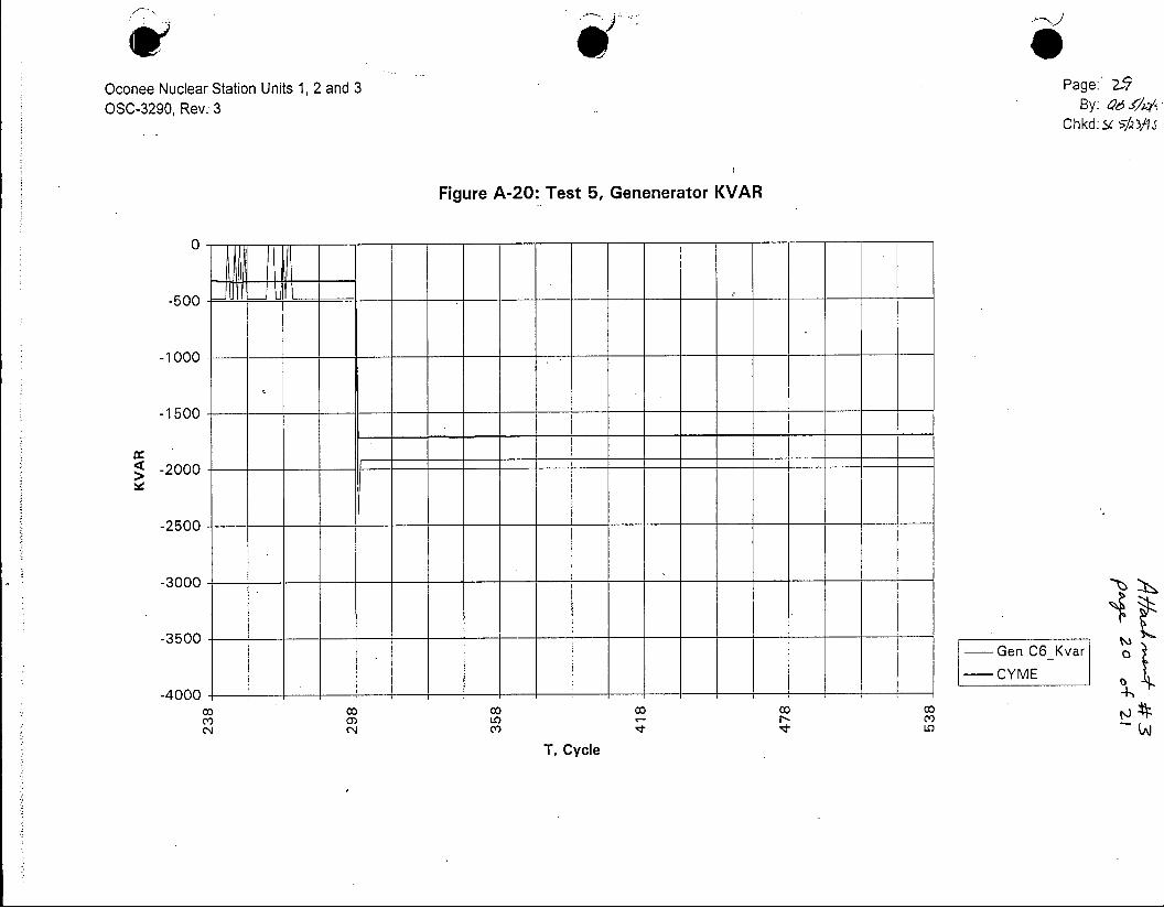
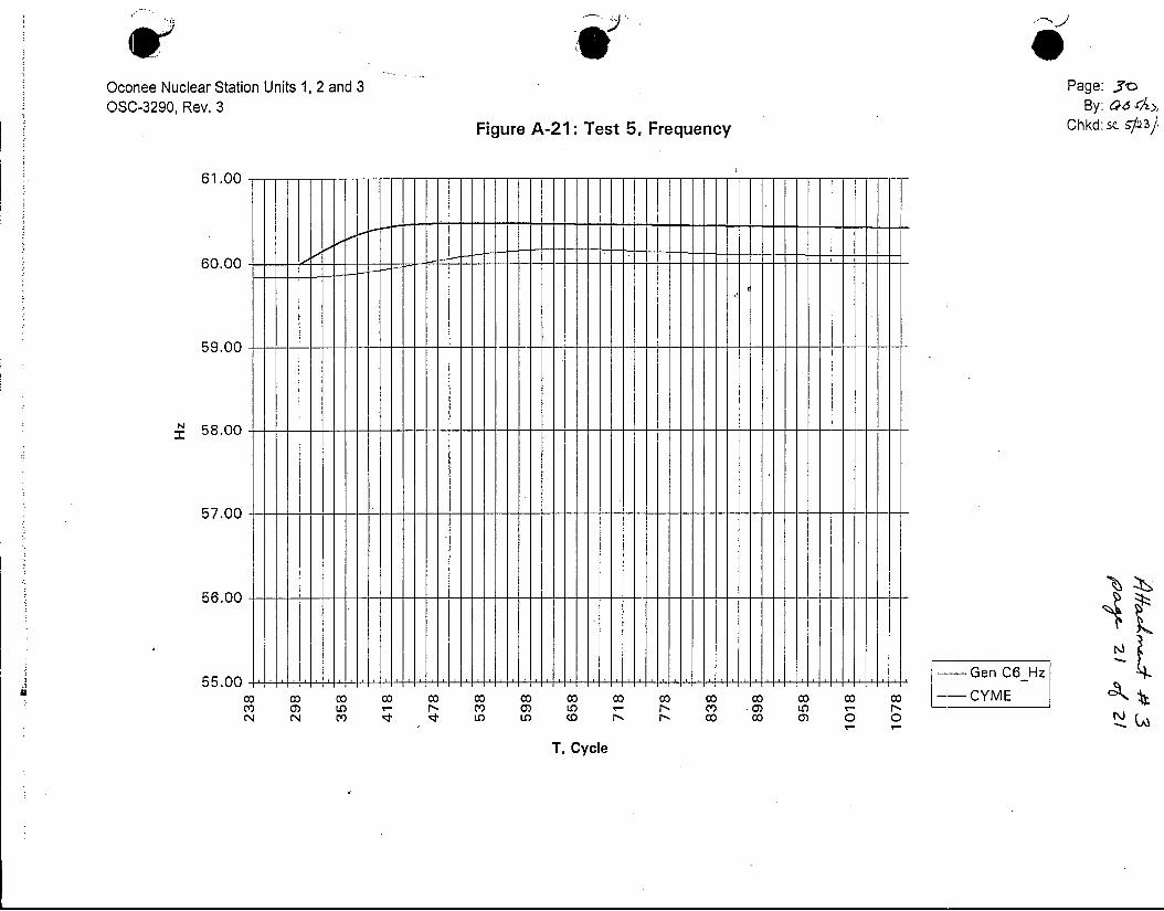
Test5: Tripping of Supercharger Fan 6C when supplied from Combustion Turbine 6C isolated from grid
For this test, the initial conditions were identical to that in Test4 above. The ASW was not running. Supercharger 6C was then tripped and the response of Combustion Turbine 6C was monitored. Note that tripping the supercharger on a unit would be expected to change the units response and is hence not a very good indication on how the unit would respond on load rejection when connected to Oconee. When a Lee unit is supplying Oconee, the supercharger on the unit would be running.
The purpose of the above tests was to verify the CYME modeling of the motors, the combustion turbines and the circuit connecting LEE to Oconee.
A-2. CYMIBASE
Network models representing the systems illustrated in figures A-1, A-2, A-3, and A-4 were created using CYMBASE. As illustrated in figure A-2, the system for Test3 was represented as a generator connected to the 100KV Switchyard bus. CYMBASE was then used to create files for input to CYMFLOW. The following are the input and output file names for each test:
Oconee Nuclear 1, 2 and 3 ZI Page: 5 OSC-3290, Rev. 3 By: 06 5123/f
Chkd: tS2a/q(
Table A-1 CYMBASE Files Created for Each Field Test
Field Test CYMBASE *.NET Files CYMBASE Ouput Files for Load Flow
Test2 TEST2.NET TEST2.NND Test3 TEST3.NET TEST3.NND Test4 TEST4.NET TEST4.NND Test5 TEST5.NET TEST5.NND
FOR Test2,Test4, and TestS, generator data is from Attachment 2. For Test3, generator data is based on Attachment 3. Initial loads and generator data was obtained from Tables E-1,E-2,E-3 and E-4(See Appendix E). All initial loading was modeled as static loads in CYMBASE.
100KV System 4
13.8/105KV 13.8/105KV 13.8/105KV 8 !MSU 4c 5 MSU5C MSU6C
13.8 KV SWGR 13.8 KV SWGR 13.8KVWR
13.81 13.8f 13.81 13.8/ 13.81 114.16KV 0.48KV M
4 .16KV 8KV 4.16K To±48Kv
.09j.34MVA .079+j.034MVA 002j.O42MVA
GEN
Super Charger fan 4C Super Charner fan SC Super Charger fan 6C 3600 HiP (Start) 3500 HP (Start) 3500 HIP
On: 3.174+jl.277MVA
Fig. A-1: TEST2 - Start ol Supercharger SC from Combustion Turbine 6C

Oconee Nuclear 1, 2 and 3 P 3 2 1 Page: 6 OSC-3290, Rev. 3 By: O/ 51.3//
Chkd:$c. s-/R3q.'4
100KV System Equivalent
00KV System 4 7 Based on Attachment 4
13.8/105KY 5MSU SC
13.8 KV SWGR
13.81 113.8/ (416 0.48KV
.079+j.034MVA
O Super Charger fan SC 3500 HP (Start)
Fig. A-2: TEST3 - Start of Supercharger SC from the 100KV Grid
100KV System 4
I 13. 8KV
11 Moto aasMVAR MS Central13.8 KV SWGR
1 -.ee5MVAR138
122
Super Charger fan 6C 3500 HP On: 3.188jl-25 MVA
Fig. A-3: TEST4 - Start ol ASW Pump Mtr from Combustion Turbine 6C

Oconee Nuclear 1, 2 and 3 pa L/ cli Page: 7 OSC-3290, Rev. 3 By: qO s) Z/23
Chkd: Sc syc/q--f
100kV System 4
-.885MVAR 13.8/105KV
1 1 MSU6C
Central 13.8 KV SWGR.
.asM VAR 12 a13.58 dl3.8/
CS 4.16 KV 0.* 48KV. 13
12301 u Stby Bus 0.071o0.05. MVA
GEN
6 0 Super Charger fan SC 3500 HP On: 3.188+jl.25 MVA
Fig. A-4: TESTS - Tripping of Supercharger 6C
Oconee Nuclear Station Units 1, 2, 3 Page:/OSC-3290, Rev. 3 By: _ -/
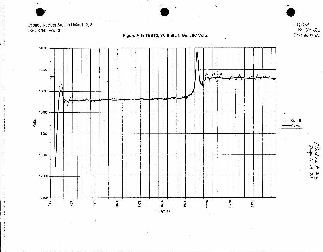
Figure A-5: TEST2, SC 5 Start, Gen. 6C Volts Chkd:5e s/A/q:
14000
13800
13600 --
13400
-- Gen. 6 CYME
13200
13000 -----
12800
12600
C0 CO
T, Cycles

Oconee Nuclear Station Units 1,2,3 Page: /j.. *OSC-3290, Rev. 3 BY: ao -37z3/
Figure A-6: Test 2, SC 5 Start, Frequency C hk d:~e A/V7?
60 - - - - - - - - - - - - - - - - -- -- - - - -
59.9
5Ge.. 6
-CI+
59.4 - - - - - - - - -- - - - -- - - -- - - - - -- -- - -- - - - -- - - -- -- - -
59.3 -------- - - - - - - - - - - - - - - - - - - - -- -
(A)
co 00 CD co co 00 00000 -2 2 N N CN
T, Cycle

?I) Oconee Nuclear Station Units 1, 2, 3 Pag e:/A
030-3290, Rev. 3 By:4~/ Figure A-7 C h kd: S. L/?j
Test 2, SC 5 Start, Voltage
4500 -------------- - - - - --- ---- V FV
4000
35en. 6
----- - T -]T -- CYME 2000 - -------------------
2000
00 0N 0o C) 0 0 ) 0N c) 000
N - - N N4 TCycle C.

Oconee Nuclear Station, Units 1,2 and 3 Page: /7 OSC-3290, Rev. 3 By: 0.6 da
Figure A-8: Test2, SC 5 Start, Gen 5 Chkd: !gc./1 Power
10050.2
9059.2
8059.2 - --
7059.2
6059.2 - - --- --5059.2 -Gen. 6
-CYME
4059.2 - -------
3059.2
2059.2
1059.2 - - - -
- C) O )N to co NN N
T, Cycle
Page 1

00 no
Voltage (
N)) 4l) c
0 cn 0 (n 0 01 0 0 0 0 0 0 0 0 0 0 0 0 (lDC(D
1044- - mhi
1344-__
1644-__
1
CD
1944-_ __
C/)
2244- ___
_ _ CA)
0 CD 2544-.
00
CD =r
CD
2844- ____
C)
3444 - a
3744
_________P_ I. p
12 <rn

00 C/) 0
KW (D
o~~r (D 0 0 0
o0 0 0 0 0 0 0 0 0 0 0 0 C
1044 __ _ cCl)
1344- Fl CL) CL
1644-__
1944- ci
CA)
cn CD
p2244- 0 0 02 CD
CD
0
C)
2544
2444-__
< 0)
m J(
I-(CV

Oconee Nuclear Station Units 1, 2 and 3 Page: ZO
OSC-3290, Rev. 3 BY: Chkd:se sapy~
Figure A-i 1: TEST3, SC 5 AMPERES
2500
2000
1500---------
500 - --------
0- TEST 3
0.
-CYME 0) -. C4D0
N' 041 '~ CCV4 CY)
T, CYCLE
Page 1

00 c:oo
KVAR C
N) 0) CC) 0 ) -
o 0 0 0 0 0 0 x ) o 0 0 0 0 0 0 CD CD
0 0 0 0 0 0 0 0 <a 1044- -wc
1344-__
CA)
1644
-n
1944
o) 2244m -)-<
Co
m
cn
2544._ _ 3
2844 ___
3144
CfA
Oconee Nuclear Station Units 1, 2 and 3 Page: 22.
OSC-3290, Rev. 3 By:dd/ Chkdse
Figure A-13: TEST4, ASW START, STANDBY BUS VOLTS
4620.0 -
4600.0-_ _ _ _~..
4580.0- -TEST -CYME
4560.0
4540.0-o
4520.0
4500.0
4480.0
4460.0
4440.0
T C) 0) Cyl co I)'~t LO N CN N N
T, Cycle
-.. AJ

Oconee Nuclear Station Units 1, 2 and 3 Page: 2-3 OSC-3290, Rev.0 By: q. 4O/A
Chkd:sc sps/1:
Figure A-14: TEST4, ASW START, MOTOR AMPERES
250.0
200.0 _---TEST
-CYME
150.0
CL
E
100.0
50.0
0.0
CT) CC)y N N4 NNN
T, Cycle

Oconee Nuclear Station Units 1, 2 and 3 Page: 2Y
OSC-3290, Rev. 0 By: r/1, Chkd:&C MS&
Figure A-1 5: TEST4, ASW START, MOTOR KW
800
7001- - --
600 ---- TEST
- CYME
500
400
300 - -
200
100
00
-100
T, Cycle
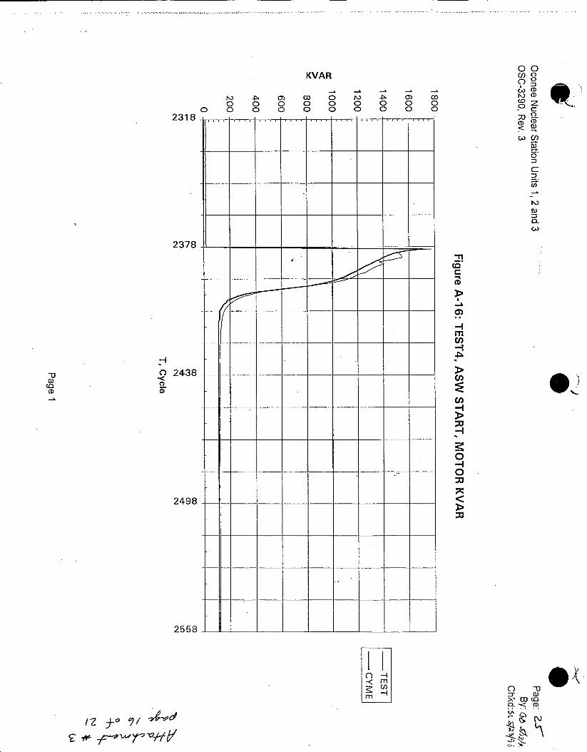
00 KVAR cn 0
C 0 0 0o 00 0 0(0D
00 0 0 0 0 0 0 0 0.
0
CL
2378-_ _ _
CD
m
.r h
(D CD
2498
2558 ... [ _ 1__ _ _ __ _ __ _
cn0 -
Oconee Nuclear Station Units 1, 2 and 3 Page: 74 OSC-3290 By: a 0f/2
Chkd: /Ash5
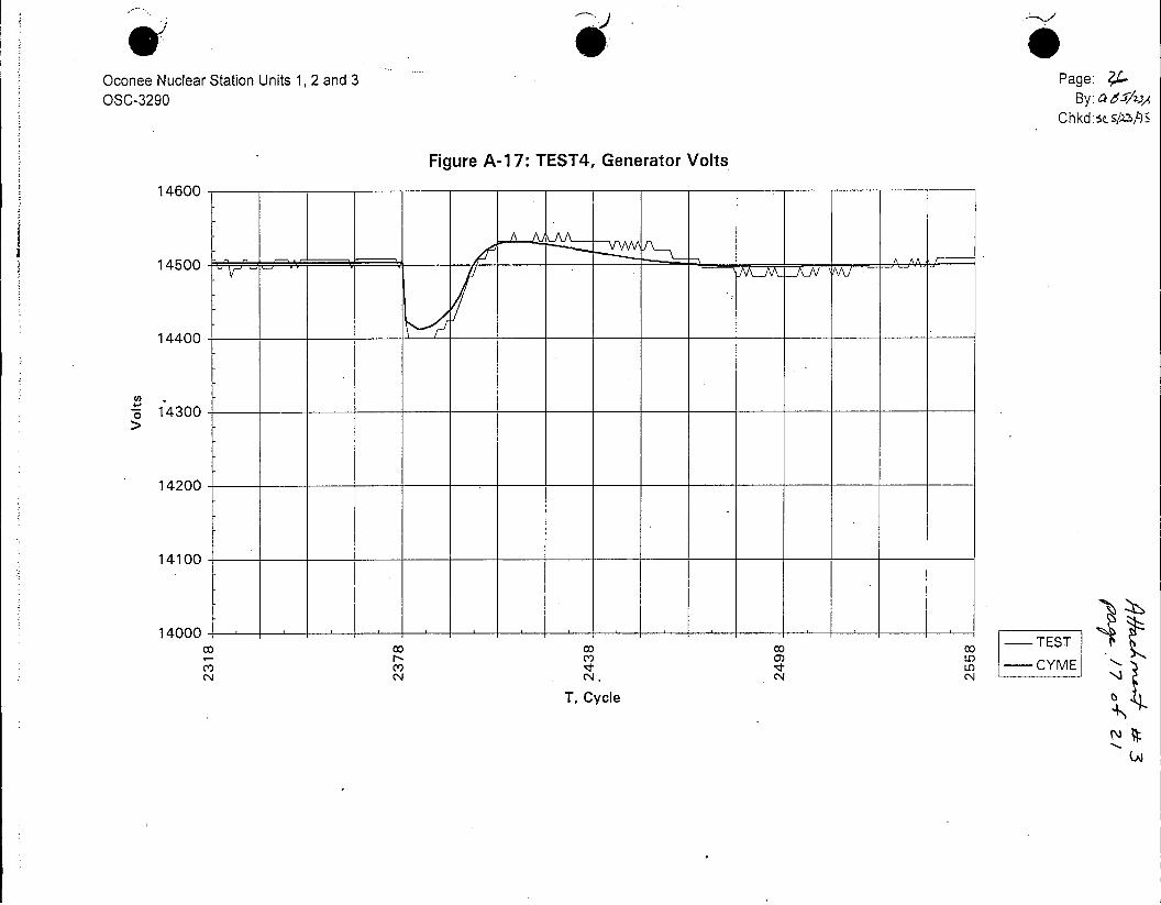
Figure A-17: TEST4, Generator Volts
14600
14500 --- A
14400
6 14300
14200
14100
14000 00 00co - TEST
r- CY) 0)m V m- CYME
T, Cycle

Oconee Nuclear Station Units 1, 2 and 3 Page: OSC-3290, Rev. 3 By:p, r
Chkd:St LA3
Figure A-18, Test 5, Gen Voltage
14630_
14580 _
14530 _ _
11180 -
14430
14380
CO C) )
T, Cycle GenC6V1 -CYME

Oconee Nuclear Station Units 1, 2 and 3 Page: zLF
OSC-3290, Rev. 3 By: 46 7/M, Chkd:.S 5?3b
Figure A-1 9: Test 5, Generator KW
3500
3000
2500 -
2000
1500
1000--
500 --
0---- --- Gen C6_Kw
0 0 co o co co - CYME
T, Cycle
CA)
Oconee Nuclear Station Units 1, 2 and 3 Page: 2-9 OSC-3290, Rev. 3 By: a, #4
Chk d: 5'/2 3
Figure A-20: Test 5, Genenerator KVAR
0
-500
-1000_
-1500
-2000- ---
-2500
-3000
-3500 Gen C6_Kvar
- CYME -4000 -+
0, 0Cycl m'~ a) LO) - r
T, Cycle
m e Oconee Nuclear Station Units 1, 2 and 3 Page: 3e OSC-3290, Rev. 3 By: Od ,
Figure A-21: Test 5, Frequency Chkd:se c3
61.00
60.00
59.00
58.00
57.00
56.00- - - - - - - - - - -
5.-Gen C6 Hz 55.00 f I I i
c 00 o co 0 0 0 0 00 0 0 0 0 -- CYME C 0) LO r, m' m) L) r N C') 10) LO . N
oN C m -I LOe O D o co 0) N
T, Cycle

ATTACHMENT 4
0I

Keowee Hydro Testing
Testing of Keowee has been reviewed and determined to be acceptable to ensure the units as
designed and maintained will function as intended when required.
Keowee Design:
To meet design basis Keowee has to be capable to: 1. Start on ES (if not presently running) 2. Accelerate to voltage and frequency capable of satisfactorily starting loads within
committed times 3. Start the loads and continuously supply them
OR 4. Separate from the grid and continue to run until needed
5. Satisfactorily start loads within committed times and continuously supply them
OCONEE TESTS Tests Presently Performing:
1. Keowee Emergency Start Test Annual Periodic Surveillance TS related (4.6.2.a, 4.6.2.b) Verifies Keowee's ability to:
(1) emergency start, (2) accelerate to rated speed and voltage within committed time and, (3) supply the sum of the loads needed to be powered during a worse case accident.
2. Emergency Power Switching Logic Test Oconee Unit Refueling Cycle Periodic Surveillance TS related (4.6.4) Verifies the proper operation of breakers and transfer logic needed to align the Oconee loads to the appropriate power path. Demonstrates Keowee's ability to:
(1) emergency start, (2) accept block loads (z 2 MVA) from a steady state (speed NO-LOAD) condition
Typically during this test Keowee carries this load ;1 hour. During a past recent test, problems with Lee source required Keowee to carry the loads z 4 hours.
NOTE: Pre- 1987 Emergency Power Switching Logic Test Performed slightly different than present test. Along with testing the EPSL logic, the Keowee U/G unit was verified to emergency start
and accept block load at ; 11 seconds while accelerating.
3. Degraded Grid Test One Oconee Unit Refueling Cycle Periodic Surveillance "NEW' TS related (3.7.7.1) Demonstrates the following:
(1) Keowee Unit separate from the system grid (ie. load reject) on.ES actuation, (2) proper switchyard isolate actuation, and (3) Keowee 0/H path re-energization (start-up transformers and Keowee house loads)
Keowee Hydro Testing 0 2
Test Performed in the Past (ie. one time test):
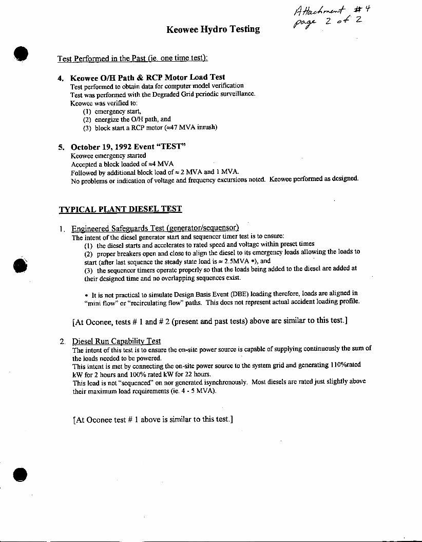
4. Keowee O/H Path & RCP Motor Load Test Test performed to obtain data for computer model verification Test was performed with the Degraded Grid periodic surveillance. Keowee was verified to:
(1) emergency start, (2) energize the O/H path, and (3) block start a RCP motor (=47 MVA inrush)
5. October 19, 1992 Event "TEST" Keowee emergency started Accepted a block loaded of m4 MVA Followed by additional block load of = 2 MVA and 1 MVA. No problems or indication of voltage and frequency excursions noted. Keowee performed as designed.
TYPICAL PLANT DIESEL TEST
1. Engineered Safeguards Test (generator/sequensor) The intent of the diesel generator start and sequencer timer test is to ensure:
(1) the diesel starts and accelerates to rated speed and voltage within preset times (2) proper breakers open and close to align the diesel to its emergency loads allowing the loads to
start (after last sequence the steady state load is = 2.5MVA *), and (3) the sequencer timers operate properly so that the loads being added to the diesel are added at
their designed time and no overlapping sequences exist.
* It is not practical to simulate Design Basis Event (DBE) loading therefore, loads are aligned in
"mini flow" or "recirculating flow" paths. This does not represent actual accident loading profile.
[At Oconee, tests # 1 and # 2 (present and past tests) above are similar to this test.]
2. Diesel Run Capability Test The intent of this test is to ensure the on-site power source is capable of supplying continuously the sum of the loads needed to be powered. This intent is met by connecting the on-site power source to the system grid and generating 1 100/orated kW for 2 hours and 100% rated kW for 22 hours. This load is not "sequenced" on nor generated isynchronously. Most diesels are rated just slightly above their maximum load requirements (ie. 4 - 5 MVA).
[At Oconee test # 1 above is similar to this test.]

ATTACHMENT 5