onsite 1052 &1063 series metro-optical transport … 1052 &1063 series metro-optical...
TRANSCRIPT

OnSite 1052 &1063 Series
Metro-Optical Transport
Access Nodes
Administrator’s Reference Guide
Sales Office:
+1 (301) 975-1000
Technical Support:
+1 (301) 975-1007
E-mail:
WWW:
www.patton.com
Part Number:
07MOS10xx-ARG, Rev. A
Revised:
November 19, 2009

Patton Electronics Company, Inc.
7622 Rickenbacker DriveGaithersburg, MD 20879 USA
Tel: +1 (301) 975-1000Fax: +1 (301) 869-9293
Support: +1 (301) 975-1007Web: www.patton.com
E-mail: [email protected]
Copyright © 2009, Patton Electronics Company. All rights reserved.
The information in this document is subject to change without notice. PattonElectronics assumes no liability for errors that may appear in this document.
The software described in this document is furnished under a license and may be usedor copied only in accordance with the terms of such license.
3
Summary Table of Contents
1 System Management Access........................................................................................................................... 21
2 System Configuration.................................................................................................................................... 35
3 STM-1 Interface ............................................................................................................................................ 72
4 E1/T1 Interface ........................................................................................................................................... 146
5 DS3/E3 Interface......................................................................................................................................... 168
6 Ethernet Interface........................................................................................................................................ 189
7 High-Density E1 Expansion Module .......................................................................................................... 214
8 High-Density Ethernet Expansion Module ................................................................................................. 225
9 High-Density DS3/E3 Expansion Module .................................................................................................. 231
10 STM-1 Expansion Module .......................................................................................................................... 236
11 Contacting Patton for assistance ................................................................................................................. 242
A Terms and Acronyms .................................................................................................................................. 245

Table of Contents
Summary Table of Contents ........................................................................................................................... 3Table of Contents ........................................................................................................................................... 4List of Figures ............................................................................................................................................... 10List of Tables ................................................................................................................................................ 13About this guide ........................................................................................................................................... 15Audience............................................................................................................................................................... 15Structure............................................................................................................................................................... 16Precautions ........................................................................................................................................................... 16Typographical conventions used in this document................................................................................................ 18
General conventions .......................................................................................................................................18Mouse conventions .........................................................................................................................................18
Safety when using electricity ................................................................................................................................. 19Power Cable ....................................................................................................................................................19
Electrostatic Discharge Damage............................................................................................................................ 20Optical Safety ....................................................................................................................................................... 20
Fiber-Optic Ports ............................................................................................................................................20Fiber-Optic Safety Precautions ........................................................................................................................20
1 System Management Access........................................................................................................................... 21Introduction ..........................................................................................................................................................22General Overview..................................................................................................................................................22Ethernet LAN Management Port...........................................................................................................................23Serial Management Port ........................................................................................................................................24Gaining Access to the System ................................................................................................................................25
Access through the Serial Port .........................................................................................................................25
Access through the Ethernet LAN Management Port ......................................................................................26Web-Based Management Interface ........................................................................................................................27
Launching the GUI Application .....................................................................................................................27Autonomous Alarm Messages ................................................................................................................................29Engineering Orderwire (EOW) .............................................................................................................................31
2 System Configuration.................................................................................................................................... 35Introduction ..........................................................................................................................................................36System Identity......................................................................................................................................................36Ethernet LAN Management Port Settings .............................................................................................................38
Configuring the Port Settings .........................................................................................................................38Changing the Default Gateway for the LAN Port ...........................................................................................39
Inband Management Channel ...............................................................................................................................39SDH Data Communications Channel (DCC) ................................................................................................40
Setting Up the IP Settings for Reaching the IMC Subnetwork ..................................................................44
4

OnSite Series Admin Reference Guide
Connecting to the Subnetwork .................................................................................................................45E1 Inband Management Channel (E1-IMC) ..................................................................................................45
Configuring the E1-IMC Settings .............................................................................................................46Configuring a Default Gateway for the E1-IMC .......................................................................................49Monitoring the E1-IMC Alarms and Performance ....................................................................................50
Timing and Synchronization .................................................................................................................................52Auto Mode Operation ....................................................................................................................................52External Commands for Timing Reference Switching .....................................................................................56S1-Byte Support ..............................................................................................................................................58External Synchronization ................................................................................................................................58
Sync Out Squelching .................................................................................................................................59Clock and NTP Server ..........................................................................................................................................59Security .................................................................................................................................................................61System Actions ......................................................................................................................................................62
Downloading System Software ........................................................................................................................62Upgrading System Software ............................................................................................................................64Resetting the System .......................................................................................................................................66Saving the System Configuration ....................................................................................................................67Restoring the Factory Default Settings ............................................................................................................67Transferring the System Configuration File ....................................................................................................68Uploading the System Log File .......................................................................................................................70
3 STM-1 Interface ............................................................................................................................................ 72Introduction ..........................................................................................................................................................74General Information..............................................................................................................................................74SDH Provisioning .................................................................................................................................................76
Enabling an STM-1 Port ................................................................................................................................76Disabling an STM-1 Port ...............................................................................................................................77Configuring the J0 Trace ................................................................................................................................78Configuring the Automatic Laser Shutdown (ALS) Function ..........................................................................78
Auto Mode ................................................................................................................................................79Manual Restart Mode ...............................................................................................................................79Manual Restart for Test Mode ..................................................................................................................79
Configuring the STM-1 in Linear 1+1 MSP Protection Mode ........................................................................80External Commands for 1+1 MSP Switching ............................................................................................81
Configuring the SDH Payload Structure .........................................................................................................83SDH and Client Port Connections........................................................................................................................86
2-way Connections .........................................................................................................................................861-way Connections .........................................................................................................................................87Drop-and-Continue Connections ...................................................................................................................88Multicast Connections ....................................................................................................................................90
SDH Alarms..........................................................................................................................................................92Monitoring SDH Alarms ................................................................................................................................92Changing SDH Alarm Default Severities ........................................................................................................94
5

OnSite Series Admin Reference Guide
Displaying the Alarm Log ...............................................................................................................................95SDH Performance Monitoring..............................................................................................................................96
Monitoring STM-1 Port Performance ............................................................................................................97Monitoring VC-n Performance .....................................................................................................................100Monitoring Pointer Justification Counts .......................................................................................................101Configuring SDH Threshold Crossing Alerts (TCA) ....................................................................................103Displaying the SDH TCA Event Log ............................................................................................................104
SDH Testing .......................................................................................................................................................105Configuring STM-1 Facility Loopback .........................................................................................................106Configuring Error Insertion ..........................................................................................................................107
Virtual Concatenation (VCAT)...........................................................................................................................108Introduction to VCAT ..................................................................................................................................108
VCAT Group Features for the OS1052 ..................................................................................................108VCAT Group Features for the OS1063 ..................................................................................................109Summary of VCAT Group Features for the OS-10-Series Systems ..........................................................109GFP Packet Transport Considerations ....................................................................................................109VCG Notation ........................................................................................................................................109Differential Delay ....................................................................................................................................110
Creating a VCG ............................................................................................................................................110Removing a VCG .........................................................................................................................................120Monitoring VCG Alarms ..............................................................................................................................121Displaying the Alarm Log .............................................................................................................................122VCAT Group Performance Monitoring ........................................................................................................122Link Capacity Adjustment Scheme (LCAS) ..................................................................................................124VCQ QoS .....................................................................................................................................................130
Subnetwork Connection Protection (SNCP).......................................................................................................132Provisioning STM-1 Ports in SNCP mode ...................................................................................................134Displaying and Configuring SNCP Path Settings .........................................................................................135Displaying and Configuring SNCP Path Status ............................................................................................136External Commands for SNCP Path Switching ............................................................................................137Creating Cross-Connections .........................................................................................................................139
Ring Operations ..................................................................................................................................................141Ring Synchronization ....................................................................................................................................141Adding and Deleting OS-10 Nodes ..............................................................................................................141
Adding OS-10 Nodes into a Ring ...........................................................................................................141Removing OS-10 Nodes from a Ring ......................................................................................................143
Linear ADM (2-Fiber).........................................................................................................................................144Interconnection of OS-10 Nodes in a 2-Fiber Linear ADM Topology ..........................................................144Synchronization of OS-10 Nodes in a 2-Fiber Linear ADM Topology .........................................................145
4 E1/T1 Interface ........................................................................................................................................... 146Introduction ........................................................................................................................................................147General Information............................................................................................................................................147E1 and T1 Provisioning.......................................................................................................................................149
6
OnSite Series Admin Reference Guide
Enabling a Port for Service ............................................................................................................................149Disabling a Port from Service ........................................................................................................................151Configuring a Port for Synchronization ........................................................................................................151Retiming Mode .............................................................................................................................................153
E1 and T1 Connections ......................................................................................................................................153Creating a Port Connection ..........................................................................................................................153
Configuring the SNCP Protection Options for E1/T1 Connections .......................................................156Configuring the J2 Trace ........................................................................................................................158
Removing a Port Connection ........................................................................................................................159E1 and T1 Alarms ...............................................................................................................................................159
Monitoring Port Alarms ................................................................................................................................159Changing Port Alarm Default Severities ........................................................................................................161Displaying the Alarm Log .............................................................................................................................161
E1 and T1 Performance Monitoring ...................................................................................................................162Monitoring E1 and T1 Port Performance .....................................................................................................162Configuring E1 and T1 Port Threshold Crossing Alerts (TCA) ....................................................................164
E1 and T1 Testing...............................................................................................................................................166Configuring E1 and T1 Terminal Loopback .................................................................................................166Configuring E1 and T1 Facility Loopback ....................................................................................................166
5 DS3/E3 Interface......................................................................................................................................... 168Introduction ........................................................................................................................................................169General Information............................................................................................................................................169DS3 and E3 Provisioning ....................................................................................................................................171
Enabling a Port for Service ............................................................................................................................171Disabling a Port from Service ........................................................................................................................173
DS3/E3 Connections ..........................................................................................................................................173Creating a Port Connection ..........................................................................................................................173
Configuring the SNCP Protection Options for DS3/E3 Connections .....................................................176Configuring the J1 Trace ........................................................................................................................177
Removing a Port Connection ........................................................................................................................178DS3/E3 Alarms ...................................................................................................................................................178
Monitoring Port Alarms ................................................................................................................................178Changing Port Alarm Default Severities ........................................................................................................180Displaying the Alarm Log .............................................................................................................................180
DS3/E3 Performance Monitoring .......................................................................................................................181Monitoring DS3/E3 Line Performance .........................................................................................................181Monitoring DS3/E3 Path Performance .........................................................................................................183Configuring DS3/E3 Port Threshold Crossing Alerts (TCA) ........................................................................184
TCA Settings for DS3/E3 Ports at the Line Level ....................................................................................184TCA Settings for DS3/E3 Ports at the Path Level ...................................................................................186
DS3/E3 Testing...................................................................................................................................................186Configuring DS3/E3 Terminal Loopback .....................................................................................................186Configuring DS3/E3 Facility Loopback ........................................................................................................187
7

OnSite Series Admin Reference Guide
6 Ethernet Interface........................................................................................................................................ 189Introduction ........................................................................................................................................................190General Information............................................................................................................................................190Ethernet Provisioning ..........................................................................................................................................191
Enabling a Port for Service ............................................................................................................................191Disabling a Port from Service ........................................................................................................................192Configuring the Port Settings .......................................................................................................................192
Autonegotiation ......................................................................................................................................193Flow Control ...........................................................................................................................................193Port Rate Control ....................................................................................................................................194Ethernet Port QoS ..................................................................................................................................195
Ethernet Connections..........................................................................................................................................197VLAN and SP-VLAN Connections ..............................................................................................................198C-Tag Connections .......................................................................................................................................201S-Tag Connections .......................................................................................................................................202Creating a Connection ..................................................................................................................................204Removing a Connection ...............................................................................................................................208
Ethernet Alarms...................................................................................................................................................208Monitoring Port Alarms ................................................................................................................................208Changing Port Alarm Default Severities ........................................................................................................209
Ethernet Port Statistics ........................................................................................................................................210Ethernet Testing..................................................................................................................................................212
7 High-Density E1 Expansion Module .......................................................................................................... 214Introduction ........................................................................................................................................................215Installing the HD-E1 Module .............................................................................................................................218Provisioning the HD-E1 Module ........................................................................................................................219Module Alarms....................................................................................................................................................221Timing Features on the HD-E1 Module .............................................................................................................221
Derived Timing from E1 Line ......................................................................................................................221
External Timing Inputs .................................................................................................................................222Retiming Mode .............................................................................................................................................222
Downloading Expansion Module Firmware ........................................................................................................223
8 High-Density Ethernet Expansion Module ................................................................................................. 225Introduction ........................................................................................................................................................226Installing the HD-ENET Module .......................................................................................................................227Provisioning the HD-ENET Module ..................................................................................................................228Module Alarms....................................................................................................................................................230Downloading Expansion Module Firmware ........................................................................................................230
9 High-Density DS3/E3 Expansion Module .................................................................................................. 231Introduction ........................................................................................................................................................232Installing the DS3/E3 Module.............................................................................................................................232Provisioning the DS3/E3 Module........................................................................................................................233Module Alarms....................................................................................................................................................235
8
OnSite Series Admin Reference Guide
Downloading Expansion Module Firmware ........................................................................................................235
10 STM-1 Expansion Module .......................................................................................................................... 236Introduction ........................................................................................................................................................237Installing the STM-1 Module..............................................................................................................................238Provisioning the STM-1 Module.........................................................................................................................239Module Alarms....................................................................................................................................................241Synchronization...................................................................................................................................................241Downloading Expansion Module Firmware ........................................................................................................241
11 Contacting Patton for assistance ................................................................................................................. 242Introduction ........................................................................................................................................................243Contact information............................................................................................................................................243Warranty Service and Returned Merchandise Authorizations (RMAs).................................................................243
Warranty coverage ........................................................................................................................................243Out-of-warranty service ...........................................................................................................................243Returns for credit ....................................................................................................................................243Return for credit policy ...........................................................................................................................244
RMA numbers ..............................................................................................................................................244Shipping instructions ..............................................................................................................................244
A Terms and Acronyms .................................................................................................................................. 245Abbreviations.......................................................................................................................................................246
9

List of Figures
1 Serial and LAN Management Ports on the Base OS1052 and OS1063 Systems . . . . . . . . . . . . . . . . . . . . . . . . 222 Detail of the Management Ports . . . . . . . . . . . . . . . . . . . . . . . . . . . . . . . . . . . . . . . . . . . . . . . . . . . . . . . . . . . . 233 Location of Signal Pins on the RJ-45 Plug . . . . . . . . . . . . . . . . . . . . . . . . . . . . . . . . . . . . . . . . . . . . . . . . . . . . 234 Web-Based Management GUI Frames . . . . . . . . . . . . . . . . . . . . . . . . . . . . . . . . . . . . . . . . . . . . . . . . . . . . . . . 285 Configuring an SNMP Trap Receiver . . . . . . . . . . . . . . . . . . . . . . . . . . . . . . . . . . . . . . . . . . . . . . . . . . . . . . . . 296 Configuring an Authorized OnSight NMS Server . . . . . . . . . . . . . . . . . . . . . . . . . . . . . . . . . . . . . . . . . . . . . . 307 Location of EOW port (AUX 1) on OS-10 Series Chassis . . . . . . . . . . . . . . . . . . . . . . . . . . . . . . . . . . . . . . . . 318 Location of signal pins on the EOW port (AUX 1) RJ-11 connector . . . . . . . . . . . . . . . . . . . . . . . . . . . . . . . . 329 Configuring the Engineering Orderwire (EOW) Function . . . . . . . . . . . . . . . . . . . . . . . . . . . . . . . . . . . . . . . . 3310 Configuring the System Identity . . . . . . . . . . . . . . . . . . . . . . . . . . . . . . . . . . . . . . . . . . . . . . . . . . . . . . . . . . . . 3711 Configuring the Ethernet LAN Management Port . . . . . . . . . . . . . . . . . . . . . . . . . . . . . . . . . . . . . . . . . . . . . . 3812 Example of IMC Using the SDH DCC in a Ring Subnetwork . . . . . . . . . . . . . . . . . . . . . . . . . . . . . . . . . . . . . 4113 Example of IMC Using the SDH DCC in a Point-to-Point Subnetwork . . . . . . . . . . . . . . . . . . . . . . . . . . . . . 4214 Configuring the SDH DCC . . . . . . . . . . . . . . . . . . . . . . . . . . . . . . . . . . . . . . . . . . . . . . . . . . . . . . . . . . . . . . . 4415 E1-IMC Application 1: Direct Point-to-Point . . . . . . . . . . . . . . . . . . . . . . . . . . . . . . . . . . . . . . . . . . . . . . . . . 4616 E1-IMC Application 2: Point-to-Point Across SDH Network . . . . . . . . . . . . . . . . . . . . . . . . . . . . . . . . . . . . . 4617 Configuring the E1 Inband Management Channel . . . . . . . . . . . . . . . . . . . . . . . . . . . . . . . . . . . . . . . . . . . . . . 4918 Example of Using the E1-IMC in a Point-to-Point Subnetwork . . . . . . . . . . . . . . . . . . . . . . . . . . . . . . . . . . . . 5019 Configuring the System Timing Mode . . . . . . . . . . . . . . . . . . . . . . . . . . . . . . . . . . . . . . . . . . . . . . . . . . . . . . . 5520 Configuring the External Commands for Switching Timing References . . . . . . . . . . . . . . . . . . . . . . . . . . . . . . 5721 Configuring Access to an NTP Server . . . . . . . . . . . . . . . . . . . . . . . . . . . . . . . . . . . . . . . . . . . . . . . . . . . . . . . . 6022 Downloading and Installing the System Software . . . . . . . . . . . . . . . . . . . . . . . . . . . . . . . . . . . . . . . . . . . . . . . 6423 Upgrading the System Software . . . . . . . . . . . . . . . . . . . . . . . . . . . . . . . . . . . . . . . . . . . . . . . . . . . . . . . . . . . . 6524 Transferring the System Configuration File . . . . . . . . . . . . . . . . . . . . . . . . . . . . . . . . . . . . . . . . . . . . . . . . . . . 6925 Uploading the System Log File . . . . . . . . . . . . . . . . . . . . . . . . . . . . . . . . . . . . . . . . . . . . . . . . . . . . . . . . . . . . . 7126 STM-1 AU-4 Multiplexing Structure . . . . . . . . . . . . . . . . . . . . . . . . . . . . . . . . . . . . . . . . . . . . . . . . . . . . . . . . 7427 STM-1 Ports on the Base OS1052 and OS1063 Systems . . . . . . . . . . . . . . . . . . . . . . . . . . . . . . . . . . . . . . . . . 7528 Enabling an STM-1 Port . . . . . . . . . . . . . . . . . . . . . . . . . . . . . . . . . . . . . . . . . . . . . . . . . . . . . . . . . . . . . . . . . 7729 Enabling and Configuring 1+1 MSP Protection . . . . . . . . . . . . . . . . . . . . . . . . . . . . . . . . . . . . . . . . . . . . . . . . 8130 Configuring the External 1+1 MSP Protection Switch Commands . . . . . . . . . . . . . . . . . . . . . . . . . . . . . . . . . . 8231 Subdivision of STM-1 Payload Structures . . . . . . . . . . . . . . . . . . . . . . . . . . . . . . . . . . . . . . . . . . . . . . . . . . . . . 8432 Notation for SDH Structures within the OnSite OS-10-series STM-1 Interfaces . . . . . . . . . . . . . . . . . . . . . . . 8433 Configuring the STM-1 Payload Structure . . . . . . . . . . . . . . . . . . . . . . . . . . . . . . . . . . . . . . . . . . . . . . . . . . . . 8534 Unprotected 2-way Connections (Examples) . . . . . . . . . . . . . . . . . . . . . . . . . . . . . . . . . . . . . . . . . . . . . . . . . . 8635 Protected 2-way Connections (Examples) . . . . . . . . . . . . . . . . . . . . . . . . . . . . . . . . . . . . . . . . . . . . . . . . . . . . . 8736 1-way Add Connections (Examples) . . . . . . . . . . . . . . . . . . . . . . . . . . . . . . . . . . . . . . . . . . . . . . . . . . . . . . . . . 8737 1-way Drop Connections (Examples) . . . . . . . . . . . . . . . . . . . . . . . . . . . . . . . . . . . . . . . . . . . . . . . . . . . . . . . . 8838 1-way Drop-and-Continue Connections (Examples) . . . . . . . . . . . . . . . . . . . . . . . . . . . . . . . . . . . . . . . . . . . . 8939 2-way Drop-and-Continue Connections (Examples) . . . . . . . . . . . . . . . . . . . . . . . . . . . . . . . . . . . . . . . . . . . . 9040 1-way Multicast Connections (Examples) . . . . . . . . . . . . . . . . . . . . . . . . . . . . . . . . . . . . . . . . . . . . . . . . . . . . . 9141 Displaying SDH Alarms . . . . . . . . . . . . . . . . . . . . . . . . . . . . . . . . . . . . . . . . . . . . . . . . . . . . . . . . . . . . . . . . . . 9342 Changing SDH Alarm Severities . . . . . . . . . . . . . . . . . . . . . . . . . . . . . . . . . . . . . . . . . . . . . . . . . . . . . . . . . . . . 9543 Displaying Current PM Data for an STM-1 Port . . . . . . . . . . . . . . . . . . . . . . . . . . . . . . . . . . . . . . . . . . . . . . . 9744 Displaying PM Data Intervals for an STM-1 Port . . . . . . . . . . . . . . . . . . . . . . . . . . . . . . . . . . . . . . . . . . . . . . 9845 Displaying Current PM Data for All STM-1 Ports . . . . . . . . . . . . . . . . . . . . . . . . . . . . . . . . . . . . . . . . . . . . . . 9946 Displaying Current VC-12 PM Data . . . . . . . . . . . . . . . . . . . . . . . . . . . . . . . . . . . . . . . . . . . . . . . . . . . . . . . 10047 Selecting Pointer Locations for PJC Monitoring . . . . . . . . . . . . . . . . . . . . . . . . . . . . . . . . . . . . . . . . . . . . . . . 102
10

Model 6081RC Network Access Server Getting Started Guide
48 Displaying PM Data for PJC Counts . . . . . . . . . . . . . . . . . . . . . . . . . . . . . . . . . . . . . . . . . . . . . . . . . . . . . . . 10249 STM-1 Facility Loopback . . . . . . . . . . . . . . . . . . . . . . . . . . . . . . . . . . . . . . . . . . . . . . . . . . . . . . . . . . . . . . . . 10550 Activating STM-1 Facility Loopback . . . . . . . . . . . . . . . . . . . . . . . . . . . . . . . . . . . . . . . . . . . . . . . . . . . . . . . 10651 Inserting STM-1 Errors . . . . . . . . . . . . . . . . . . . . . . . . . . . . . . . . . . . . . . . . . . . . . . . . . . . . . . . . . . . . . . . . . 10752 Provisioning a VCG at the VC-3 Level . . . . . . . . . . . . . . . . . . . . . . . . . . . . . . . . . . . . . . . . . . . . . . . . . . . . . . 11353 Configuring the SNCP Settings of a VCG at the VC-3 Level . . . . . . . . . . . . . . . . . . . . . . . . . . . . . . . . . . . . . 11454 Configuring the Properties of a VC-3 VCG Member . . . . . . . . . . . . . . . . . . . . . . . . . . . . . . . . . . . . . . . . . . . 11555 Provisioning a VCG at the VC-12 Level . . . . . . . . . . . . . . . . . . . . . . . . . . . . . . . . . . . . . . . . . . . . . . . . . . . . . 11856 Configuring the Properties of a VC-12 VCG Member . . . . . . . . . . . . . . . . . . . . . . . . . . . . . . . . . . . . . . . . . . 12057 Displaying Current PM Data for VCGs . . . . . . . . . . . . . . . . . . . . . . . . . . . . . . . . . . . . . . . . . . . . . . . . . . . . . 12358 Displaying Current PM Data for All VCGs . . . . . . . . . . . . . . . . . . . . . . . . . . . . . . . . . . . . . . . . . . . . . . . . . . 12459 Creating New VCG Members . . . . . . . . . . . . . . . . . . . . . . . . . . . . . . . . . . . . . . . . . . . . . . . . . . . . . . . . . . . . 12660 Adding VCG Members to the LCAS (So) Function . . . . . . . . . . . . . . . . . . . . . . . . . . . . . . . . . . . . . . . . . . . . 12761 Completion of the Add to LCAS (So) Operation . . . . . . . . . . . . . . . . . . . . . . . . . . . . . . . . . . . . . . . . . . . . . . 12862 Completion of the Remove from LCAS (So) Operation . . . . . . . . . . . . . . . . . . . . . . . . . . . . . . . . . . . . . . . . . 12963 Application of VCG QoS for the Aggregation of Ethernet Flows into a VCG . . . . . . . . . . . . . . . . . . . . . . . . 13064 Configuring the VCG QoS Functions . . . . . . . . . . . . . . . . . . . . . . . . . . . . . . . . . . . . . . . . . . . . . . . . . . . . . . 13165 Ring ADM Interconnection Example . . . . . . . . . . . . . . . . . . . . . . . . . . . . . . . . . . . . . . . . . . . . . . . . . . . . . . . 13266 SNCP Modes . . . . . . . . . . . . . . . . . . . . . . . . . . . . . . . . . . . . . . . . . . . . . . . . . . . . . . . . . . . . . . . . . . . . . . . . . 13367 Configuring STM-1 Ports in SNCP Mode . . . . . . . . . . . . . . . . . . . . . . . . . . . . . . . . . . . . . . . . . . . . . . . . . . . 13468 Displaying and Configuring the SNCP Path Settings . . . . . . . . . . . . . . . . . . . . . . . . . . . . . . . . . . . . . . . . . . . 13569 Displaying and Configuring the SNCP Path Status . . . . . . . . . . . . . . . . . . . . . . . . . . . . . . . . . . . . . . . . . . . . 13670 Configuring the External Commands for SNCP Path Switching . . . . . . . . . . . . . . . . . . . . . . . . . . . . . . . . . . 13871 Creating VC-12 Cross-Connections . . . . . . . . . . . . . . . . . . . . . . . . . . . . . . . . . . . . . . . . . . . . . . . . . . . . . . . . 14072 OS-10 Operation in 2-Fiber (Unprotected) Linear ADM Mode . . . . . . . . . . . . . . . . . . . . . . . . . . . . . . . . . . . 14573 E1 and T1 Multiplexing over SDH . . . . . . . . . . . . . . . . . . . . . . . . . . . . . . . . . . . . . . . . . . . . . . . . . . . . . . . . 14774 E1 and T1 Ports on the Base OS1052 and OS1063 Systems . . . . . . . . . . . . . . . . . . . . . . . . . . . . . . . . . . . . . 14875 OS1063 with two 21-port E1 Expansion Modules . . . . . . . . . . . . . . . . . . . . . . . . . . . . . . . . . . . . . . . . . . . . . 14876 Displaying E1 and T1 Ports . . . . . . . . . . . . . . . . . . . . . . . . . . . . . . . . . . . . . . . . . . . . . . . . . . . . . . . . . . . . . . 15077 Enabling an E1 or a T1 Port . . . . . . . . . . . . . . . . . . . . . . . . . . . . . . . . . . . . . . . . . . . . . . . . . . . . . . . . . . . . . . 15078 Configuring the Sync In and Sync Out Options . . . . . . . . . . . . . . . . . . . . . . . . . . . . . . . . . . . . . . . . . . . . . . . 15279 Connecting an E1 or a T1 port to a TU-12 . . . . . . . . . . . . . . . . . . . . . . . . . . . . . . . . . . . . . . . . . . . . . . . . . . 15580 Displaying E1 and T1 connections . . . . . . . . . . . . . . . . . . . . . . . . . . . . . . . . . . . . . . . . . . . . . . . . . . . . . . . . . 15681 Unprotected E1 or T1 Connections . . . . . . . . . . . . . . . . . . . . . . . . . . . . . . . . . . . . . . . . . . . . . . . . . . . . . . . . 15682 Protecting E1 and T1 Connections Using SNCP . . . . . . . . . . . . . . . . . . . . . . . . . . . . . . . . . . . . . . . . . . . . . . 15783 Configuring the J2 Trace . . . . . . . . . . . . . . . . . . . . . . . . . . . . . . . . . . . . . . . . . . . . . . . . . . . . . . . . . . . . . . . . 15884 Displaying E1 and T1 Port Alarms . . . . . . . . . . . . . . . . . . . . . . . . . . . . . . . . . . . . . . . . . . . . . . . . . . . . . . . . . 16085 Displaying Current PM Data for E1 and T1 Ports . . . . . . . . . . . . . . . . . . . . . . . . . . . . . . . . . . . . . . . . . . . . . 16386 Displaying Current PM Data for All E1 and T1 Ports . . . . . . . . . . . . . . . . . . . . . . . . . . . . . . . . . . . . . . . . . . 16487 E1 and T1 Terminal Loopback . . . . . . . . . . . . . . . . . . . . . . . . . . . . . . . . . . . . . . . . . . . . . . . . . . . . . . . . . . . . 16688 E1 and T1 Facility Loopback . . . . . . . . . . . . . . . . . . . . . . . . . . . . . . . . . . . . . . . . . . . . . . . . . . . . . . . . . . . . . 16689 Activating E1 Loopback . . . . . . . . . . . . . . . . . . . . . . . . . . . . . . . . . . . . . . . . . . . . . . . . . . . . . . . . . . . . . . . . . 16790 DS3 and E3 Multiplexing over SDH . . . . . . . . . . . . . . . . . . . . . . . . . . . . . . . . . . . . . . . . . . . . . . . . . . . . . . . 16991 DS3 and E3 Ports on the 3-Port DS3/E3 Module . . . . . . . . . . . . . . . . . . . . . . . . . . . . . . . . . . . . . . . . . . . . . 17092 Displaying DS3/E3 Ports . . . . . . . . . . . . . . . . . . . . . . . . . . . . . . . . . . . . . . . . . . . . . . . . . . . . . . . . . . . . . . . . 17293 Enabling a DS3/E3 Port . . . . . . . . . . . . . . . . . . . . . . . . . . . . . . . . . . . . . . . . . . . . . . . . . . . . . . . . . . . . . . . . . 17294 Connecting a DS3/E3 Port to a TU-3 . . . . . . . . . . . . . . . . . . . . . . . . . . . . . . . . . . . . . . . . . . . . . . . . . . . . . . 17595 Displaying DS3/E3 Connections . . . . . . . . . . . . . . . . . . . . . . . . . . . . . . . . . . . . . . . . . . . . . . . . . . . . . . . . . . 17596 Protecting DS3/E3 Connections Using SNCP . . . . . . . . . . . . . . . . . . . . . . . . . . . . . . . . . . . . . . . . . . . . . . . . 17697 Configuring the J1 Trace . . . . . . . . . . . . . . . . . . . . . . . . . . . . . . . . . . . . . . . . . . . . . . . . . . . . . . . . . . . . . . . . 17798 Displaying DS3/E3 Port Alarms . . . . . . . . . . . . . . . . . . . . . . . . . . . . . . . . . . . . . . . . . . . . . . . . . . . . . . . . . . . 179
11

Model 6081RC Network Access Server Getting Started Guide
99 Displaying Current Line PM Data for DS3/E3 Ports . . . . . . . . . . . . . . . . . . . . . . . . . . . . . . . . . . . . . . . . . . . 182100 Displaying Current Line PM Data for All DS3/E3 Ports . . . . . . . . . . . . . . . . . . . . . . . . . . . . . . . . . . . . . . . . 182101 Displaying Path PM Data for DS3/E3 Ports . . . . . . . . . . . . . . . . . . . . . . . . . . . . . . . . . . . . . . . . . . . . . . . . . . 184102 DS3/E3 Terminal Loopback . . . . . . . . . . . . . . . . . . . . . . . . . . . . . . . . . . . . . . . . . . . . . . . . . . . . . . . . . . . . . . 186103 DS3/E3 Facility Loopback . . . . . . . . . . . . . . . . . . . . . . . . . . . . . . . . . . . . . . . . . . . . . . . . . . . . . . . . . . . . . . . 187104 Activating DS3/E3 Loopback . . . . . . . . . . . . . . . . . . . . . . . . . . . . . . . . . . . . . . . . . . . . . . . . . . . . . . . . . . . . . 188105 Ethernet Ports on the Base OS1052 System . . . . . . . . . . . . . . . . . . . . . . . . . . . . . . . . . . . . . . . . . . . . . . . . . . 190106 OS1063 with two Ethernet Expansion Modules . . . . . . . . . . . . . . . . . . . . . . . . . . . . . . . . . . . . . . . . . . . . . . . 190107 Enabling an Ethernet port . . . . . . . . . . . . . . . . . . . . . . . . . . . . . . . . . . . . . . . . . . . . . . . . . . . . . . . . . . . . . . . 192108 Configuring the Autonegotiation Option . . . . . . . . . . . . . . . . . . . . . . . . . . . . . . . . . . . . . . . . . . . . . . . . . . . . 193109 Configuring the Flow Control Option . . . . . . . . . . . . . . . . . . . . . . . . . . . . . . . . . . . . . . . . . . . . . . . . . . . . . . 194110 Configuring the Port Rate Control . . . . . . . . . . . . . . . . . . . . . . . . . . . . . . . . . . . . . . . . . . . . . . . . . . . . . . . . . 195111 Application of Port QoS for the Aggregation of Ethernet Flows . . . . . . . . . . . . . . . . . . . . . . . . . . . . . . . . . . . 195112 Configuring the Ethernet Port QoS Function . . . . . . . . . . . . . . . . . . . . . . . . . . . . . . . . . . . . . . . . . . . . . . . . . 196113 Single Flow from a Port into a Dedicated VCG . . . . . . . . . . . . . . . . . . . . . . . . . . . . . . . . . . . . . . . . . . . . . . . 197114 Multiple Flows from a Port into Dedicated VCGs . . . . . . . . . . . . . . . . . . . . . . . . . . . . . . . . . . . . . . . . . . . . . 198115 Multiple Flows from Multiple Ports into a Shared VCG . . . . . . . . . . . . . . . . . . . . . . . . . . . . . . . . . . . . . . . . 198116 Dedicated Ethernet Port and VLAN Flow Connections . . . . . . . . . . . . . . . . . . . . . . . . . . . . . . . . . . . . . . . . . 199117 Shared Ethernet VLAN Flow Connections . . . . . . . . . . . . . . . . . . . . . . . . . . . . . . . . . . . . . . . . . . . . . . . . . . . 199118 Dedicated Ethernet SP-VLAN Flow Connection . . . . . . . . . . . . . . . . . . . . . . . . . . . . . . . . . . . . . . . . . . . . . . 200119 Shared Ethernet SP-VLAN Flow Connections . . . . . . . . . . . . . . . . . . . . . . . . . . . . . . . . . . . . . . . . . . . . . . . . 200120 Shared Ethernet Port Flows Using C-Tag Connections . . . . . . . . . . . . . . . . . . . . . . . . . . . . . . . . . . . . . . . . . 201121 Shared Ethernet VLAN Flows Using S-Tag Connections . . . . . . . . . . . . . . . . . . . . . . . . . . . . . . . . . . . . . . . . 202122 Shared Ethernet Port Flows Using S-Tag Connections . . . . . . . . . . . . . . . . . . . . . . . . . . . . . . . . . . . . . . . . . . 203123 Shared Ethernet Port and VLAN Flows Using S-Tag Connections . . . . . . . . . . . . . . . . . . . . . . . . . . . . . . . . . 203124 Creating an Ethernet Flow . . . . . . . . . . . . . . . . . . . . . . . . . . . . . . . . . . . . . . . . . . . . . . . . . . . . . . . . . . . . . . . 206125 Connecting an Ethernet Flow to a VCG . . . . . . . . . . . . . . . . . . . . . . . . . . . . . . . . . . . . . . . . . . . . . . . . . . . . . 207126 Removing an Ethernet Flow from a VCG . . . . . . . . . . . . . . . . . . . . . . . . . . . . . . . . . . . . . . . . . . . . . . . . . . . . 208127 Displaying Ethernet Port Alarms . . . . . . . . . . . . . . . . . . . . . . . . . . . . . . . . . . . . . . . . . . . . . . . . . . . . . . . . . . 209128 Changing Ethernet Port Alarm Settings . . . . . . . . . . . . . . . . . . . . . . . . . . . . . . . . . . . . . . . . . . . . . . . . . . . . . 210129 Displaying Ethernet Port Statistics . . . . . . . . . . . . . . . . . . . . . . . . . . . . . . . . . . . . . . . . . . . . . . . . . . . . . . . . . 211130 Ethernet Terminal Loopback . . . . . . . . . . . . . . . . . . . . . . . . . . . . . . . . . . . . . . . . . . . . . . . . . . . . . . . . . . . . . 212131 Activating Ethernet Port Terminal Loopback . . . . . . . . . . . . . . . . . . . . . . . . . . . . . . . . . . . . . . . . . . . . . . . . . 213132 HD-E1 Module . . . . . . . . . . . . . . . . . . . . . . . . . . . . . . . . . . . . . . . . . . . . . . . . . . . . . . . . . . . . . . . . . . . . . . . 215133 Installing the HD-E1 Module . . . . . . . . . . . . . . . . . . . . . . . . . . . . . . . . . . . . . . . . . . . . . . . . . . . . . . . . . . . . . 218134 Provisioning the HD-E1 Module . . . . . . . . . . . . . . . . . . . . . . . . . . . . . . . . . . . . . . . . . . . . . . . . . . . . . . . . . . 220135 Download Firmware into the Expansion Modules . . . . . . . . . . . . . . . . . . . . . . . . . . . . . . . . . . . . . . . . . . . . . 224136 HD-ENET Module . . . . . . . . . . . . . . . . . . . . . . . . . . . . . . . . . . . . . . . . . . . . . . . . . . . . . . . . . . . . . . . . . . . . 226137 Installing the HD-ENET Module . . . . . . . . . . . . . . . . . . . . . . . . . . . . . . . . . . . . . . . . . . . . . . . . . . . . . . . . . 228138 Provisioning the HD-ENET Module . . . . . . . . . . . . . . . . . . . . . . . . . . . . . . . . . . . . . . . . . . . . . . . . . . . . . . . 229139 Location of LEDs for Ethernet Ports on the HD-ENET Module . . . . . . . . . . . . . . . . . . . . . . . . . . . . . . . . . . 230140 DS3/E3 Module . . . . . . . . . . . . . . . . . . . . . . . . . . . . . . . . . . . . . . . . . . . . . . . . . . . . . . . . . . . . . . . . . . . . . . . 232141 Installing the DS3/E3 Module . . . . . . . . . . . . . . . . . . . . . . . . . . . . . . . . . . . . . . . . . . . . . . . . . . . . . . . . . . . . 233142 Provisioning the DS3/E3 Module . . . . . . . . . . . . . . . . . . . . . . . . . . . . . . . . . . . . . . . . . . . . . . . . . . . . . . . . . . 234143 STM-1 Optical and Electrical Interface Modules . . . . . . . . . . . . . . . . . . . . . . . . . . . . . . . . . . . . . . . . . . . . . . 237144 Installing the STM-1 Optical Interface Module . . . . . . . . . . . . . . . . . . . . . . . . . . . . . . . . . . . . . . . . . . . . . . . 239145 Provisioning the STM-1 Optical Interface Module . . . . . . . . . . . . . . . . . . . . . . . . . . . . . . . . . . . . . . . . . . . . . 240
12

List of Tables
1 General conventions . . . . . . . . . . . . . . . . . . . . . . . . . . . . . . . . . . . . . . . . . . . . . . . . . . . . . . . . . . . . . . . . . . . . . 182 Mouse conventions . . . . . . . . . . . . . . . . . . . . . . . . . . . . . . . . . . . . . . . . . . . . . . . . . . . . . . . . . . . . . . . . . . . . . . 183 Ethernet LAN Management Port Cabling Specifications . . . . . . . . . . . . . . . . . . . . . . . . . . . . . . . . . . . . . . . . . 234 Pin Assignments for the Ethernet LAN Management Port . . . . . . . . . . . . . . . . . . . . . . . . . . . . . . . . . . . . . . . . 245 Pin Assignments for the RS-232 Serial Management Port . . . . . . . . . . . . . . . . . . . . . . . . . . . . . . . . . . . . . . . . . 246 RS-232 Serial Port Parameters . . . . . . . . . . . . . . . . . . . . . . . . . . . . . . . . . . . . . . . . . . . . . . . . . . . . . . . . . . . . . 247 VT100 Terminal Emulation Settings . . . . . . . . . . . . . . . . . . . . . . . . . . . . . . . . . . . . . . . . . . . . . . . . . . . . . . . . 248 Web-Based Management GUI Frame Descriptions . . . . . . . . . . . . . . . . . . . . . . . . . . . . . . . . . . . . . . . . . . . . . 289 Description of Fields on the System Information Page . . . . . . . . . . . . . . . . . . . . . . . . . . . . . . . . . . . . . . . . . . . 3710 Inband Management Channels on the OS-10 Series System . . . . . . . . . . . . . . . . . . . . . . . . . . . . . . . . . . . . . . . 4011 DCC Properties . . . . . . . . . . . . . . . . . . . . . . . . . . . . . . . . . . . . . . . . . . . . . . . . . . . . . . . . . . . . . . . . . . . . . . . . 4012 DCC Byte Structure . . . . . . . . . . . . . . . . . . . . . . . . . . . . . . . . . . . . . . . . . . . . . . . . . . . . . . . . . . . . . . . . . . . . . 4013 E1-IMC Properties . . . . . . . . . . . . . . . . . . . . . . . . . . . . . . . . . . . . . . . . . . . . . . . . . . . . . . . . . . . . . . . . . . . . . . 4514 Table Entries for Active E1-IMC Alarms . . . . . . . . . . . . . . . . . . . . . . . . . . . . . . . . . . . . . . . . . . . . . . . . . . . . . 5015 E1 Path Error Performance Events for the E1-IMC . . . . . . . . . . . . . . . . . . . . . . . . . . . . . . . . . . . . . . . . . . . . . 5116 System Timing Modes . . . . . . . . . . . . . . . . . . . . . . . . . . . . . . . . . . . . . . . . . . . . . . . . . . . . . . . . . . . . . . . . . . . 5217 Timing References for Synchronization in Auto Mode . . . . . . . . . . . . . . . . . . . . . . . . . . . . . . . . . . . . . . . . . . . 5218 Timing States . . . . . . . . . . . . . . . . . . . . . . . . . . . . . . . . . . . . . . . . . . . . . . . . . . . . . . . . . . . . . . . . . . . . . . . . . . 5319 Criteria for Declaring an Input Timing Reference as Unavailable . . . . . . . . . . . . . . . . . . . . . . . . . . . . . . . . . . . 5320 Switch Operation Types for Timing . . . . . . . . . . . . . . . . . . . . . . . . . . . . . . . . . . . . . . . . . . . . . . . . . . . . . . . . . 5521 External Commands for Timing Reference Switching . . . . . . . . . . . . . . . . . . . . . . . . . . . . . . . . . . . . . . . . . . . 5622 SSM Codes and Quality Levels Supported on the OS-10 . . . . . . . . . . . . . . . . . . . . . . . . . . . . . . . . . . . . . . . . . 5823 User Types and Privileges . . . . . . . . . . . . . . . . . . . . . . . . . . . . . . . . . . . . . . . . . . . . . . . . . . . . . . . . . . . . . . . . . 6124 Software Image Memory Partitions . . . . . . . . . . . . . . . . . . . . . . . . . . . . . . . . . . . . . . . . . . . . . . . . . . . . . . . . . . 6225 STM-1 Interconnection Parameters . . . . . . . . . . . . . . . . . . . . . . . . . . . . . . . . . . . . . . . . . . . . . . . . . . . . . . . . . 7526 Summary of S-1.1, L-1.1 and L-1.2 Optical Interface Parameters . . . . . . . . . . . . . . . . . . . . . . . . . . . . . . . . . . . 7527 External Commands for 1+1 MSP Switching . . . . . . . . . . . . . . . . . . . . . . . . . . . . . . . . . . . . . . . . . . . . . . . . . . 8128 Index Letters to Identify SDH Structures . . . . . . . . . . . . . . . . . . . . . . . . . . . . . . . . . . . . . . . . . . . . . . . . . . . . . 8329 Provisioning Range for SDH Structures . . . . . . . . . . . . . . . . . . . . . . . . . . . . . . . . . . . . . . . . . . . . . . . . . . . . . . 8330 Default SDH Payload Structure . . . . . . . . . . . . . . . . . . . . . . . . . . . . . . . . . . . . . . . . . . . . . . . . . . . . . . . . . . . . 8431 SDH Alarms . . . . . . . . . . . . . . . . . . . . . . . . . . . . . . . . . . . . . . . . . . . . . . . . . . . . . . . . . . . . . . . . . . . . . . . . . . . 9232 STM-1 Alarm Status LED . . . . . . . . . . . . . . . . . . . . . . . . . . . . . . . . . . . . . . . . . . . . . . . . . . . . . . . . . . . . . . . . 9333 Table Entries for Active SDH Alarms . . . . . . . . . . . . . . . . . . . . . . . . . . . . . . . . . . . . . . . . . . . . . . . . . . . . . . . . 9334 SDH Alarm Default Severities . . . . . . . . . . . . . . . . . . . . . . . . . . . . . . . . . . . . . . . . . . . . . . . . . . . . . . . . . . . . . 9435 SDH Error Performance Events . . . . . . . . . . . . . . . . . . . . . . . . . . . . . . . . . . . . . . . . . . . . . . . . . . . . . . . . . . . . 9636 Monitored PM Parameters at Various SDH Layers . . . . . . . . . . . . . . . . . . . . . . . . . . . . . . . . . . . . . . . . . . . . . . 9637 SDH SES Threshold Values . . . . . . . . . . . . . . . . . . . . . . . . . . . . . . . . . . . . . . . . . . . . . . . . . . . . . . . . . . . . . . . 9738 PJC PM Parameters . . . . . . . . . . . . . . . . . . . . . . . . . . . . . . . . . . . . . . . . . . . . . . . . . . . . . . . . . . . . . . . . . . . . 10139 VCG Provisioning Rules for OS1052 Base System (Slot 1) . . . . . . . . . . . . . . . . . . . . . . . . . . . . . . . . . . . . . . . 10840 Summary of VCAT Features for the OS-10-Series . . . . . . . . . . . . . . . . . . . . . . . . . . . . . . . . . . . . . . . . . . . . . 10941 Differential Delay Support . . . . . . . . . . . . . . . . . . . . . . . . . . . . . . . . . . . . . . . . . . . . . . . . . . . . . . . . . . . . . . . 11042 VCG Alarms . . . . . . . . . . . . . . . . . . . . . . . . . . . . . . . . . . . . . . . . . . . . . . . . . . . . . . . . . . . . . . . . . . . . . . . . . . 12143 Table Entries for Active VCG Alarms . . . . . . . . . . . . . . . . . . . . . . . . . . . . . . . . . . . . . . . . . . . . . . . . . . . . . . . 121
13

Model 6081RC Network Access Server Getting Started Guide
44 GFP Alarms . . . . . . . . . . . . . . . . . . . . . . . . . . . . . . . . . . . . . . . . . . . . . . . . . . . . . . . . . . . . . . . . . . . . . . . . . . 12145 VCG PM Parameters . . . . . . . . . . . . . . . . . . . . . . . . . . . . . . . . . . . . . . . . . . . . . . . . . . . . . . . . . . . . . . . . . . . 12246 LCAS Control (CTRL) Words . . . . . . . . . . . . . . . . . . . . . . . . . . . . . . . . . . . . . . . . . . . . . . . . . . . . . . . . . . . . 12547 SNCP Path Properties . . . . . . . . . . . . . . . . . . . . . . . . . . . . . . . . . . . . . . . . . . . . . . . . . . . . . . . . . . . . . . . . . . 13548 SNCP Path Status . . . . . . . . . . . . . . . . . . . . . . . . . . . . . . . . . . . . . . . . . . . . . . . . . . . . . . . . . . . . . . . . . . . . . . 13749 External Commands for SNCP Path Switching . . . . . . . . . . . . . . . . . . . . . . . . . . . . . . . . . . . . . . . . . . . . . . . 13750 Cross-Connection Types . . . . . . . . . . . . . . . . . . . . . . . . . . . . . . . . . . . . . . . . . . . . . . . . . . . . . . . . . . . . . . . . 13951 E1 and T1 Port Interconnection Parameters . . . . . . . . . . . . . . . . . . . . . . . . . . . . . . . . . . . . . . . . . . . . . . . . . . 14852 Configuration Modes for E1 Ports 7 and 8 (OS1052) and 20 and 21 (OS1063 . . . . . . . . . . . . . . . . . . . . . . . 15153 E1 and T1 Line Alarms . . . . . . . . . . . . . . . . . . . . . . . . . . . . . . . . . . . . . . . . . . . . . . . . . . . . . . . . . . . . . . . . . . 15954 E1 or T1 Alarm Status LED . . . . . . . . . . . . . . . . . . . . . . . . . . . . . . . . . . . . . . . . . . . . . . . . . . . . . . . . . . . . . . 16055 Table Entries for Active E1 and T1 Alarms . . . . . . . . . . . . . . . . . . . . . . . . . . . . . . . . . . . . . . . . . . . . . . . . . . . 16056 E1 and T1 Line Alarm Default Severities . . . . . . . . . . . . . . . . . . . . . . . . . . . . . . . . . . . . . . . . . . . . . . . . . . . . 16157 E1 and T1 Line PM Parameters . . . . . . . . . . . . . . . . . . . . . . . . . . . . . . . . . . . . . . . . . . . . . . . . . . . . . . . . . . . 16258 DS3 and E3 Port Interconnection Parameters . . . . . . . . . . . . . . . . . . . . . . . . . . . . . . . . . . . . . . . . . . . . . . . . . 17059 DS3/E3 Line Alarms . . . . . . . . . . . . . . . . . . . . . . . . . . . . . . . . . . . . . . . . . . . . . . . . . . . . . . . . . . . . . . . . . . . . 17860 DS3/E3 Alarm Status LED . . . . . . . . . . . . . . . . . . . . . . . . . . . . . . . . . . . . . . . . . . . . . . . . . . . . . . . . . . . . . . . 17961 Table Entries for Active DS3/E3 Alarms . . . . . . . . . . . . . . . . . . . . . . . . . . . . . . . . . . . . . . . . . . . . . . . . . . . . . 17962 DS3/E3 Line Alarm Default Severities . . . . . . . . . . . . . . . . . . . . . . . . . . . . . . . . . . . . . . . . . . . . . . . . . . . . . . 18063 DS3/E3 Line PM Parameters . . . . . . . . . . . . . . . . . . . . . . . . . . . . . . . . . . . . . . . . . . . . . . . . . . . . . . . . . . . . . 18164 DS3/E3 Path PM Parameters . . . . . . . . . . . . . . . . . . . . . . . . . . . . . . . . . . . . . . . . . . . . . . . . . . . . . . . . . . . . . 18365 Ethernet Port Cabling Specifications . . . . . . . . . . . . . . . . . . . . . . . . . . . . . . . . . . . . . . . . . . . . . . . . . . . . . . . 19166 Ethernet Port Pin Assignment (RJ-45 Connector) . . . . . . . . . . . . . . . . . . . . . . . . . . . . . . . . . . . . . . . . . . . . . 19167 Ethernet Flows in the OS-10 Series . . . . . . . . . . . . . . . . . . . . . . . . . . . . . . . . . . . . . . . . . . . . . . . . . . . . . . . . 19768 C-Tag Add/Strip Tagging Operation Functions . . . . . . . . . . . . . . . . . . . . . . . . . . . . . . . . . . . . . . . . . . . . . . . 20169 S-Tag Add/Strip Tagging Operation Functions . . . . . . . . . . . . . . . . . . . . . . . . . . . . . . . . . . . . . . . . . . . . . . . 20270 Summary of Tagging Operations and Connections for Ethernet Flows . . . . . . . . . . . . . . . . . . . . . . . . . . . . . . 20471 Ethernet Port Alarms . . . . . . . . . . . . . . . . . . . . . . . . . . . . . . . . . . . . . . . . . . . . . . . . . . . . . . . . . . . . . . . . . . . 20872 Status LED for Ethernet Ports on the Base System . . . . . . . . . . . . . . . . . . . . . . . . . . . . . . . . . . . . . . . . . . . . . 20873 Table Entries for Active Ethernet Alarms . . . . . . . . . . . . . . . . . . . . . . . . . . . . . . . . . . . . . . . . . . . . . . . . . . . . 20974 Ethernet Line Alarm Default Severities . . . . . . . . . . . . . . . . . . . . . . . . . . . . . . . . . . . . . . . . . . . . . . . . . . . . . . 20975 Ethernet Port Statistics . . . . . . . . . . . . . . . . . . . . . . . . . . . . . . . . . . . . . . . . . . . . . . . . . . . . . . . . . . . . . . . . . . 21076 Product Codes for the HD-E1 Module . . . . . . . . . . . . . . . . . . . . . . . . . . . . . . . . . . . . . . . . . . . . . . . . . . . . . . 21577 Pin Assignment in a Future Bus Connector Section . . . . . . . . . . . . . . . . . . . . . . . . . . . . . . . . . . . . . . . . . . . . 21678 E1 Port Assignments for Future Bus Connector Sections . . . . . . . . . . . . . . . . . . . . . . . . . . . . . . . . . . . . . . . . 21679 Pin Assignments for E1 Ports 1–12 and 13–21 Using a 50-Pin Telco Connector . . . . . . . . . . . . . . . . . . . . . . 21780 Module Alarms . . . . . . . . . . . . . . . . . . . . . . . . . . . . . . . . . . . . . . . . . . . . . . . . . . . . . . . . . . . . . . . . . . . . . . . . 22181 ALM (Alarm Status) LED for the HD-E1 Module . . . . . . . . . . . . . . . . . . . . . . . . . . . . . . . . . . . . . . . . . . . . . 22182 Timing Feature Differences for E1 Ports on the OS-10 and the HD-E1 Module . . . . . . . . . . . . . . . . . . . . . . 22183 Ethernet Port Cabling Specifications . . . . . . . . . . . . . . . . . . . . . . . . . . . . . . . . . . . . . . . . . . . . . . . . . . . . . . . 22684 Ethernet Port Pin Assignment (RJ-45 Connector) . . . . . . . . . . . . . . . . . . . . . . . . . . . . . . . . . . . . . . . . . . . . . 22785 Status LED for Ethernet Ports on the HD-ENET Module . . . . . . . . . . . . . . . . . . . . . . . . . . . . . . . . . . . . . . . 23086 ALM (Alarm Status) LED for the HD-ENET Module . . . . . . . . . . . . . . . . . . . . . . . . . . . . . . . . . . . . . . . . . . 23087 ALM (Alarm Status) LED for the DS3/E3 Module . . . . . . . . . . . . . . . . . . . . . . . . . . . . . . . . . . . . . . . . . . . . 23588 STM-1 Port Interconnection Parameters . . . . . . . . . . . . . . . . . . . . . . . . . . . . . . . . . . . . . . . . . . . . . . . . . . . . 23789 ALM (Alarm Status) LED for STM-1 Ports . . . . . . . . . . . . . . . . . . . . . . . . . . . . . . . . . . . . . . . . . . . . . . . . . . 241
14

About this guideThis guide describes how to configure and manage a Patton OnSite Series Model 1052 and1063 Metro-Optical Transport Access Node. For detailed installation instructions, refer to the OnSite 1052 & 1063 Series Getting Started Guide, which is located on the CD-ROM that came with your unit and at www.patton.com.
Installation, maintenance, and removal of a chassis or its components must be done by qualified service per-sonnel only. Qualified service personnel have had appropriate technical training and experience that is neces-sary to be aware of the hazards to which they are exposed when performing a task and of measures to minimize the danger to themselves and other people.
You should consider the following before unpacking your equipment:
• Install the equipment in a secured, enclosed, and restricted access area, ensuring that only qualified service personnel have access to the equipment.
• Install the equipment only in a temperature and humidity-controlled indoor area that is free of airborne materials that can conduct electricity.
• When you handle equipment that has expansion modules, put on the electrostatic discharge (ESD) wrist strap to reduce the risk of electronic damage to the equipment.
Note Leave the ESD strap permanently attached to the chassis or rack so that it is always available when you need to handle ESD-sensitive components.
AudienceThis guide is intended for the following users:
• Operators
• Installers
• Maintenance technicians
Read the following safety information thoroughly before installing your OS-10 system. Failure to follow this safety information can lead to personal injury or damage to the equipment.
WARNING
15

OnSite Series Admin Reference Guide
StructureThis guide contains the following chapters and appendices:
• Chapter 1 describes how to access and manage the system
• Chapter 2 describes how to get started configuring the system
• Chapter 3 describes how to configure and manage the STM-1 interface
• Chapter 4 describes how to configure and manage the E1/T1 interface
• Chapter 5 describes how to configure and manage the DS3/E3 interface
• Chapter 6 describes how to configure and manage the Ethernet interface
• Chapter 7 describes how to install the high-density E1 expansion module
• Chapter 8 describes how to install the high-density Ethernet expansion module
• Chapter 9 describes how to install the high-density DS3/E3 expansion module
• Chapter 10 describes how to install the STM-1 expansion module
• Chapter 11 contains information on contacting Patton technical support for assistance
• Appendix A contains a reference for terms and acronyms found in this guide
For best results, read the contents of this guide before you install and configure the OS-10 platforms.
PrecautionsNotes and cautions, which have the following meanings, are used throughout this guide to help you become aware of potential problems. Warnings relate to personal injury issues, and Cautions refer to potential property damage.
Note Calls attention to important information.
The shock hazard symbol and WARNING heading indicate a potential electric shock hazard. Strictly follow the warning instructions to avoid injury caused by electric shock.
The alert symbol and WARNING heading indicate a potential safety hazard. Strictly follow the warning instructions to avoid personal injury.
WARNING
WARNING
16

OnSite Series Admin Reference Guide
The shock hazard symbol and CAUTION heading indicate a potential electric shock hazard. Strictly follow the instructions to avoid property damage caused by electric shock.
The alert symbol and CAUTION heading indicate a potential haz-ard. Strictly follow the instructions to avoid property damage.
CAUTION
CAUTION
17

OnSite Series Admin Reference Guide
Typographical conventions used in this documentThis section describes the typographical conventions and terms used in this guide.
General conventionsThe procedures described in this manual use the following text conventions:
Mouse conventionsThe following conventions are used when describing mouse actions:
Table 1. General conventions
Convention Meaning
Garamond blue type Indicates a cross-reference hyperlink that points to a figure, graphic, table, or section heading. Clicking on the hyperlink jumps you to the ref-erence. When you have finished reviewing the reference, click on the Go to Previous View button in the Adobe® Acrobat® Reader tool-bar to return to your starting point.
Futura bold type Indicates the names of menu bar options.
Italicized Futura type Indicates the names of options on pull-down menus.
Futura type Indicates the names of fields or windows.
Garamond bold type Indicates the names of command buttons that execute an action.
< > Angle brackets indicate function and keyboard keys, such as <Shift>, <Ctrl>, <C>, and so on.
Are you ready? All system messages and prompts appear in the Courier font as the system would display them.
% dir *.* Bold Courier font indicates where the operator must type a response or command
Table 2. Mouse conventions
Convention Meaning
Left mouse button This button refers to the primary or leftmost mouse button (unless you have changed the default configuration).
Right mouse button This button refers the secondary or rightmost mouse button (unless you have changed the default configuration).
Point This word means to move the mouse in such a way that the tip of the pointing arrow on the screen ends up resting at the desired location.
Click Means to quickly press and release the left or right mouse button (as instructed in the procedure). Make sure you do not move the mouse pointer while clicking a mouse button.
Double-click Means to press and release the same mouse button two times quicklyDrag This word means to point the arrow and then hold down the left or right mouse but-
ton (as instructed in the procedure) as you move the mouse to a new location. When you have moved the mouse pointer to the desired location, you can release the mouse button.
18

OnSite Series Admin Reference Guide
Safety when using electricity
Follow these guidelines when working on equipment powered by electricity:
• Locate the emergency power-off switch in the room in which you are working. Then, if an electrical acci-dent occurs, you can quickly turn off the power.
• Never assume that power is disconnected from a circuit. Disconnect all power before installing or removing a chassis or working near power supplies.
• Ground the unit. Do not connect the power supply unit to an AC outlet without a ground connection.
• Connect the unit to a grounded AC outlet to comply with the appropriate regional safety standards.
• Place the unit near the socket outlet to be easily accessible.
• Look carefully for possible hazards in your work area, such as moist floors, ungrounded power extension cables, frayed power cords, and missing safety grounds.
• Do not work alone if hazardous conditions exist.
In addition, following these guidelines when working on any equipment that is disconnected from a power source but still connected to telephone wiring or other network cabling:
• Never install telephone wiring during a lightning storm.
• Never touch uninsulated telephone wires or terminals unless the telephone line is disconnected at the net-work interface.
• Use caution when installing or modifying telephone lines.
Power CableIf your system comes with the AC power option, use an AC power cable appropriate for your country.
Check your local electrical codes and regulatory agencies for power cable requirements.
Read the installation instructions before connecting your OS-10 system to the power source.
WARNING
19

OnSite Series Admin Reference Guide
Electrostatic Discharge DamageElectrostatic discharge (ESD) can damage equipment and impair electrical circuitry. It can occur if electronic printed circuit cards are improperly handled and can cause complete or intermittent failures. Always follow these ESD prevention procedures when removing and replacing expansion modules:
• Ensure that the system chassis is electrically connected to earth ground.
• Wear an ESD-preventive wrist strap, ensuring that it makes good skin contact. Connect the clip to an unpainted surface of the chassis frame or to the rack to channel unwanted ESD voltages safely to ground. To guard against ESD damage and shocks, the wrist strap and cord must operate effectively.
• If no wrist strap is available, ground yourself by touching an unpainted metal part of the chassis or rack.
Optical Safety
Fiber-Optic PortsTo protect your eyes, never look at the transmit LED or laser through a magnifying device while it is powered on. Never look directly at a fiber port on the chassis or at the ends of fiber cable when they are powered on.
Note The OS-10 system uses a CLASS 1 laser device.
Fiber-Optic Safety PrecautionsFollow these safety precautions when working with fiber-optic cables:
• Do not eat, drink or smoke in the work area. If fiber particles are ingested they could cause internal hemor-rhaging.
• Wear safety glasses with side shields to avoid getting fiber-optic splinters in your eyes.
• Do not look into the end of a fiber cable until you are sure that there is no light source at the other end. Use a fiber-optic power meter to ensure that the fiber is dark (that is, no power is being carried).
• Ensure that the work area is well ventilated.
• Do not touch your eyes while working with fiber-optic cables.
• Wear disposable aprons to minimize fiber particles on your clothing.
• Dispose of all cut fiber-optic pieces properly.
• Thoroughly clean the work area when the installation is complete.
To prevent equipment damage because of ESD, periodically check the resistance value of the antistatic strap. It should be between 1 and 10 MΩ (Mohm).
Use fiber-optic ports only for telecommunications applications that require optical fiber. Use the ports only with the appropriate connector. When not in use, replace the dust covers. Using these interfaces in ways other than those described in this guide can cause property damage or personal injury.
CAUTION
WARNING
20

Chapter 1 System Management Access
Chapter contentsIntroduction ..........................................................................................................................................................22General Overview..................................................................................................................................................22Ethernet LAN Management Port...........................................................................................................................23Serial Management Port ........................................................................................................................................24Gaining Access to the System ................................................................................................................................25
Access through the Serial Port .........................................................................................................................25Access through the Ethernet LAN Management Port ......................................................................................26
Web-Based Management Interface ........................................................................................................................27Launching the GUI Application .....................................................................................................................27
Autonomous Alarm Messages ................................................................................................................................29Engineering Orderwire (EOW) .............................................................................................................................31
21

OnSite Series Admin Reference Guide 1 • System Management Access
IntroductionThis chapter provides the procedures for configuring and monitoring the local serial and LAN management (LM) ports, and the inband management channel (IMC) for remote management communications. The chap-ter also provides the procedures for configuring and using the Orderwire communications port (if the AUX port is factory-installed).
General OverviewThe base OnSite OS-10 system provides two management ports from which you can access the system man-agement functions. One of the management ports is an Ethernet LAN (10/100BASE-TX) port. The other is an RS-232 SERIAL port.
figure 1 shows the location of the two management ports on the base OS1052 and OS1063 systems.
Figure 1. Serial and LAN Management Ports on the Base OS1052 and OS1063 Systems
Introduction 22

OnSite Series Admin Reference Guide 1 • System Management Access
figure 2 provides a close-up view of the two management ports. The figure includes the location of the RJ-45 connector pins for both ports.
Figure 2. Detail of the Management Ports
figure 3 shows the location of the signal pins on the RJ-45 plug.
Figure 3. Location of Signal Pins on the RJ-45 Plug
Ethernet LAN Management PortThe Ethernet LAN management port complies with the following standards:
• IEEE 802.3u (PHY)
• IEEE 802.3 (MAC)
• IEEE 802.3x (flow control)
The port supports autonegotiation, which is always enabled.
table 3 provides the cabling specifications for the Ethernet LAN management port.
Table 3. Ethernet LAN Management Port Cabling Specifications
Cable Specification
Connector RJ-45Type Category 5Reach 100 m
Ethernet LAN Management Port 23

OnSite Series Admin Reference Guide 1 • System Management Access
table 4 provides the pin assignments for the RJ-45 connector.
Serial Management PortThe physical connector for the RS-232 SERIAL management port is an RJ-45 connector. table 5 provides the pin assignments for the RJ-45 connector.
Note A connector adapter is supplied with the system to allow the connec-tion of the RS-232 signal to a PC with a DB-9 connector.
table 6 lists the serial port parameters:
table 7 lists the required VT100 terminal emulation settings for the PC that connects to the serial port.
Table 4. Pin Assignments for the Ethernet LAN Management Port
Signal Name Description RJ-45 Pin
RXN Receive tip 3RXP Receive ring 6TXN Transmit tip 1TXP Transmit ring 2
Table 5. Pin Assignments for the RS-232 Serial Management Port
Signal Name Description RJ-45 Pin
RS232_TXD output Transmit data 6RS232_RXD input Receive data 3GND Ground 4 and 5
Table 6. RS-232 Serial Port Parameters
Parameter Property
Baud rate 9,600 to 38,400 (asynchronous)Data 8 bitsParity NoneStop 1 bit
Table 7. VT100 Terminal Emulation Settings
Parameter Setting
Port COM1Baud rate 9,600 Data 8 bitsParity NoneStop 1 bitFlow control None
Serial Management Port 24

OnSite Series Admin Reference Guide 1 • System Management Access
Gaining Access to the SystemThere are two ways of gaining access to the system management functions. One way is through the SERIAL port and the command line interface (CLI). The other way is through the Ethernet LAN port and the web browser interface. The following sections describe the procedures for each of the access methods.
Access through the Serial PortTo gain management access to the system for the first time through the SERIAL port, follow these steps:
1. Connect a PC to the SERIAL management port.
Note Use the DB-9-to-RJ-45 adapter cable supplied with the system.
2. Launch the VT100 terminal emulation program on the PC.
Note Configure the terminal in accordance with the settings in Table 14.
3. Press the Enter key on the PC to obtain a login prompt from the system.
4. Log in to the system using the Super user ID and password.
Note Only the Super user is able to perform the following task.
Note The user ID for the Super user is super (all lowercase letters).
Note The factory-assigned default password for the Super user is super (all lowercase letters).
After successful completion of the login, the system responds with the CLI (command-line interface) prompt.
Note The CLI command prompt for the system is OnSite >
5. Type the following CLI command to configure the IP address for the Ethernet LAN management port, and then press the Enter key:
config mgmt-enet ip-address aaa.bbb.ccc.ddd
Note aaa.bbb.ccc.ddd is the standard dotted-decimal notation.
6. Type the following CLI command to configure the net mask for the Ethernet LAN management port, and then press the Enter key:
config mgmt-enet ip-netmask aaa.bbb.ccc.ddd
7. Type the following CLI command to configure the default gateway for the Ethernet LANmanagement port, and then press the Enter key:
config mgmt-enet default-gateway aaa.bbb.ccc.ddd
Note By default, the IP address is set to 192.168.2.100, the net mask is set to 255.255.255.0, and the default gateway is set to 192.168.2.1
Gaining Access to the System 25

OnSite Series Admin Reference Guide 1 • System Management Access
8. Type the following CLI command to save the IP settings (address, net mask, and default gateway)for the Ethernet LAN management port to the system configuration file, and then press the Enter key:
save config
Note Saving the configuration is important to prevent the loss of the IP configuration data if a system reset or reboot occurs.
At this point, the system responds with Configuration Saved to indicate that the IP settings have been saved to the system. The system is now ready for operation using the Web-based management interface.
Note You may also have access to the system through Telnet. This access requires prior configuration of the IP address of the Ethernet LAN management port through the RS-232 SERIAL port, as indicated in the preceding steps.
Note The system terminates the management session for any user when the session remains inactive for 30 seconds. This termination applies to management sessions through the SERIAL port or through Telnet. The login prompt appears when the system terminates a previously active session through the SERIAL port.
Access through the Ethernet LAN Management PortTo gain management access to the system for the first time through the Ethernet LAN management (LM) port, follow these steps:
1. Connect a PC to the Ethernet LAN management port using the RJ-45 connector.
Note You may connect the PC to the system from a remote location using an IP LAN or WAN that connects to the Ethernet LAN management port.
2. Configure the PC using the factory default settings for the Ethernet LAN management port.
Note By default, the IP address is set to 192.168.2.100, the net mask is set to 255.255.255.0, and the default gateway is set to 192.168.2.1
3. Launch the Web browser of your choice, and type the default IP address of the system in the Address field of the browser.
4. Log in to the system using the super, admin, or monitor user ID and password.
Note The factory-assigned default password for the Super user is super (all lowercase letters).
Changing the IP address, net mask, and default gateway settings for the Ethernet LAN management port could result in the loss-of-management connectivity to the system, if the connection is cur-rently through that port.CAUTION
Gaining Access to the System 26

OnSite Series Admin Reference Guide 1 • System Management Access
See “Web-Based Management Interface” on page 27 for a description of the Web-based management interface features. Once you gain access to the system through the Ethernet LAN port, you may change the IP settings for the port for secure access in the future.
Note Once the changes take place, you will loose connectivity to the sys-tem, but you can regain access immediately by typing the new IP address of the system in the Address field of the browser.
Web-Based Management InterfaceThe system provides a simple but powerful Web-based management interface to configure and monitor the OnSite OS-10 system. This graphical user interface (GUI) is called the OnSight Device Manager (DM) and is accessible through a Web browser using Hypertext Transfer Protocol (HTTP).
Note The system supports the following Web browsers: Microsoft Internet Explorer 6+, Netscape 7+, Mozilla 1.7+, and Mozilla Firefox 1.0+ on Windows, Solaris, and Linux platforms.
The OnSight DM allows you to have full access to the system management functions. These functions include the ability to set up or change all configurable items on the system and the ability to create and delete connec-tions between the client ports and SDH network interface. The interface also allows you to monitor and dis-play current active alarms, performance monitoring parameters, and alarm and event logs.
Launching the GUI ApplicationTo launch the Web-based management interface, follow these steps:
Note This procedure requires prior configuration of the IP address of the Ethernet LAN management port through the RS-232 SERIAL port or LAN port, as indicated in §6.4.
1. Connect the PC to the Ethernet LAN management port using the RJ-45 connector.
Note You may connect the PC to the system from a remote location using an IP LAN or WAN that connects to the Ethernet LAN management port.
2. Launch the Web browser of your choice, and type the IP address of the system in the Address field of the browser.
3. Log in to the system using the super, admin, or monitor user ID and password.
After successful completion of the login, the browser displays the OnSight DM splash screen from which you can select the language of your choice (English or Chinese, currently). After language selection, the browser
Save the system configuration to prevent the loss of the new IP settings if a system reboot occurs.
CAUTION
Web-Based Management Interface 27

OnSite Series Admin Reference Guide 1 • System Management Access
displays the System Information page. The OnSight DM screen is divided into three frames, as shown in figure 4. table 8 provides a description of each frame.
You may now start to configure and operate the system using the GUI interface.
Note For proper display of the GUI interface, you must set your browser to allow “pop-up” windows.
Figure 4. Web-Based Management GUI Frames
Table 8. Web-Based Management GUI Frame Descriptions
GUI Frames Provides...
Status (top frame) An overview of the system identity, including the system name and IP address, and the support contact information and status of active alarms.
Navigation (bottom left frame) The main categories and subdivisions of system functions.Content (bottom right frame) The main area for information display and configuration.
Web-Based Management Interface 28

OnSite Series Admin Reference Guide 1 • System Management Access
Autonomous Alarm MessagesYou can configure the system to generate autonomous alarm messages that can be received and displayed by an SNMP-based network management system (NMS).
By default, the system does not generate SNMP traps. To allow the generation of SNMP traps, you must first configure the IP address of the NMS host device or devices to which you wish to direct the traps.
To configure the system as an SNMP trap sender for an SNMP trap receiver, see Figure 12 and follow these steps:
1. Select the SYSTEM folder from the navigation menu.
2. From the expanded SYSTEM folder, select Management Access.
3. From the expanded Management Access folder, select Trap Receiver.
4. On the SNMP Trap Receivers page, click on Add.
5. In the Add New Trap Receiver page, type the Trap Receiver Address and Community String.
Note The community string controls access between a client (the OS-10 system) and a server (the NMS host).
6. Set the Version to configure the system to send SNMP V1 or V2 traps.
7. Type the Source Agent Address of the SNMP agent.
Note The OS-10 generates SNMP traps that contain the IP address of the source agent. By default, the system uses the address of the Ethernet LAN management port as the source agent address. However, you may use another address (for example, the inband management chan-nel address) according to the routing settings for the system.
8. Click on Close to close the window.
At this point, the Trap Receivers page displays the settings for the new receiver.
Figure 5. Configuring an SNMP Trap Receiver
Autonomous Alarm Messages 29
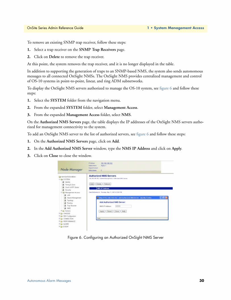
OnSite Series Admin Reference Guide 1 • System Management Access
To remove an existing SNMP trap receiver, follow these steps:
1. Select a trap receiver on the SNMP Trap Receivers page.
2. Click on Delete to remove the trap receiver.
At this point, the system removes the trap receiver, and it is no longer displayed in the table.
In addition to supporting the generation of traps to an SNMP-based NMS, the system also sends autonomous messages to all connected OnSight NMSs. The OnSight NMS provides centralized management and control of OS-10 systems in point-to-point, linear, and ring ADM subnetworks.
To display the OnSight NMS servers authorized to manage the OS-10 system, see figure 6 and follow these steps:
1. Select the SYSTEM folder from the navigation menu.
2. From the expanded SYSTEM folder, select Management Access.
3. From the expanded Management Access folder, select NMS.
On the Authorized NMS Servers page, the table displays the IP addresses of the OnSight NMS servers autho-rized for management connectivity to the system.
To add an OnSight NMS server to the list of authorized servers, see figure 6 and follow these steps:
1. On the Authorized NMS Servers page, click on Add.
2. In the Add Authorized NMS Server window, type the NMS IP Address and click on Apply.
3. Click on Close to close the window.
Figure 6. Configuring an Authorized OnSight NMS Server
Autonomous Alarm Messages 30

OnSite Series Admin Reference Guide 1 • System Management Access
Engineering Orderwire (EOW)If the system is equipped with the factory-installed AUX (auxiliary) board, you can use AUX port 1 (AUX 1) for voice communications between two or more interconnected OnSite OS-10 Series systems.
figure 7 shows the location of EOW port (AUX 1) on the system. The port is located on the right side of the chassis, at the back.
Figure 7. Location of EOW port (AUX 1) on OS-10 Series Chassis
The EOW port supports a 2-wire analog interface (tip and ring) with a nominal impedance of 900-ohm and A-law PCM voice encoding. The system carries the PCM-encoded 64 kbit/s voice channel in either the E1 or E2 byte of the STM-1 section overheard (SOH).
As a Foreign eXchange Station (FXS) interface, the EOW port supports the following functions:
• Dial tone
• Battery current
• Ring voltage
The system uses an RJ-11 connector for the EOW port (AUX 1) but only two pins are used for the 2-wire con-nection: pin 2 (tip) and pin 3 (ring), as shown in figure 8.
Note The “tip” is the ground side and the “ring” is the battery side of the 2-wire telephone circuit.
Engineering Orderwire (EOW) 31

OnSite Series Admin Reference Guide 1 • System Management Access
Figure 8. Location of signal pins on the EOW port (AUX 1) RJ-11 connector
The EOW port supports dual-tone multifrequency (DTMF) signaling to identify EOW stations within an OnSite OS-10 subnetwork. Each EOW station is identified with a programmable 3-digit station ID number.
To configure the engineering orderwire (EOW) function, see Figure 16 and follow these steps:
1. Select the SYSTEM folder from the navigation menu.
2. From the expanded SYSTEM folder, select Management Access.
3. From the expanded Management Access folder, select Orderwire.
Note If you see that the physical connector for the AUX 1 port is present but the Orderwire selection does not appear on the folder, check first that the system is operating using Release 4.3 or above.
4. On the Orderwire page, check that the AUX Board shows Installed and that the Operational Status is in-service (IS).
Note If the AUX Board shows Not Installed or the Operational Status is out-of-service (OOS), and you see that the physical connector for the AUX1 port is present, contact your local systems engineer or regional OnSite support center for additional technical information.
5. On the Orderwire page, set the Station ID for the system.
Note The Station ID needs to be a unique 3-digit number for each EOW station within an OnSite subnetwork. The available range of station ID numbers is 001 to 255.
To prevent electrical shock, never touch uninsulated wires or terminals when the phone line is plugged into the RJ-11 connector of the EOW port (AUX 1).
WARNING
Engineering Orderwire (EOW) 32

OnSite Series Admin Reference Guide 1 • System Management Access
Note In addition to supporting selective calling of EOW stations using the station ID, the EOW also supports a party-line function that allows calling and communicating with all EOW stations at once (party-line function) by dialing *000.
6. Set the Channel Byte to E2 (express orderwire byte) if there are SDH regenerators present between the STM-1 ports connecting two OnSite OS-10 nodes supporting the EOW function; otherwise, leave the default setting as E1 (local orderwire byte).
7. Set Termination to Termination Point if the EOW station is an OS-10 node in terminal mux configura-tion in a point-to-point link or at the end of a linear ADM chain. For OS-10 nodes in ADM configura-tion, leave the default setting as Intermediate Point.
Note For OS-10 nodes in a ring network, one of the nodes must be set to Termination Point while the rest of the nodes are set to Intermediate Point. This arrangement is necessary to prevent an audio feedback loop. Normally, the OS-10 node serving as the master timing node for the ring is set to Termination Point.
8. Click on Apply to complete the configuration of the EOW port.
Figure 9. Configuring the Engineering Orderwire (EOW) Function
After the EOW port is configured for operation, you can connect a regular 2-wire touchtone telephone set to the RJ-11 connector of the port. To establish a voice call with another EOW station on the same OnSite OS-10 subnetwork, take the phone “off-hook”, wait for dial tone, and then dial star (*) followed by the Station ID number. For example, to call Station ID number 123, dial *123.
Note To use the EOW function, all OS-10 nodes in the subnetwork must be equipped with the factory-installed AUX board option. The nodes must also be configured with a unique station ID number for each node.
Engineering Orderwire (EOW) 33

OnSite Series Admin Reference Guide 1 • System Management Access
At this point, the called station begins to ring if another telephone set is connected to the EOW port of that station.
Note To call and communicate with all EOW stations at once (party-line function), dial *000.
To complete the call, simply place the telephone set in the on-hook position, like a regular analog phone.
Engineering Orderwire (EOW) 34

Chapter 2 System Configuration
Chapter contentsIntroduction ..........................................................................................................................................................36System Identity......................................................................................................................................................36Ethernet LAN Management Port Settings .............................................................................................................38
Configuring the Port Settings .........................................................................................................................38Changing the Default Gateway for the LAN Port ...........................................................................................39
Inband Management Channel ...............................................................................................................................39SDH Data Communications Channel (DCC) ................................................................................................40
Setting Up the IP Settings for Reaching the IMC Subnetwork ..................................................................44Connecting to the Subnetwork .................................................................................................................45
E1 Inband Management Channel (E1-IMC) ..................................................................................................45Configuring the E1-IMC Settings .............................................................................................................46Configuring a Default Gateway for the E1-IMC .......................................................................................49Monitoring the E1-IMC Alarms and Performance ....................................................................................50
Timing and Synchronization .................................................................................................................................52Auto Mode Operation ....................................................................................................................................52External Commands for Timing Reference Switching .....................................................................................56S1-Byte Support ..............................................................................................................................................58External Synchronization ................................................................................................................................58
Sync Out Squelching .................................................................................................................................59Clock and NTP Server ..........................................................................................................................................59Security .................................................................................................................................................................61System Actions ......................................................................................................................................................62
Downloading System Software ........................................................................................................................62Upgrading System Software ............................................................................................................................64
Resetting the System .......................................................................................................................................66Saving the System Configuration ....................................................................................................................67Restoring the Factory Default Settings ............................................................................................................67Transferring the System Configuration File ....................................................................................................68Uploading the System Log File .......................................................................................................................70
35

OnSite Series Admin Reference Guide 2 • System Configuration
IntroductionThis chapter provides the procedures for configuring the global system attributes. These attributes include the system identity and IP settings for management communications using the local and inband management channels. It also provides procedures for configuring the system timing and synchronization functions and set-ting up the system clock. The chapter concludes with procedures for upgrading the system software, rebooting and resetting the system defaults, and transferring configuration and log files between the system and a remote server.
System IdentityTo configure the system identity, see Figure 17 and follow these steps:
1. Select the SYSTEM folder from the navigation menu.
2. From the expanded SYSTEM folder, select Identity.
3. On the System Information page, type the System Name, Location, and Support Contact.
Note In Location, type the location of the system by using a physical address or any other network-specific site notation. Leave this field empty, if desired.
Note In System Name, type any suitable name that identifies the system. Leave this field empty, if desired. The System Name appears on the Status frame at the top of the browser page.
Note In Support Contact, type the e-mail address of the nearest support center or systems engineer servicing the system. Leave this field empty if desired. The Support Contact appears on the Status frame at the top of the browser page. When you click on the e-mail address, your email application opens a new message window to allow sending a message to your support contact.
Note You may use up to 100 characters for the Location, System Name and Support Contact. The string can contain only the following alphanumeric characters: lower case letters (a through z), upper case letters (A through Z), numbers (0 through 9), hyphens (-), commas (,), colons (:), underscores (_), slashes (/), periods (.), spaces, paren-theses, and the @ character.
4. Click on Apply to complete this task.
Table 9 on page 37 provides a description of all fields on the system information page.
Introduction 36
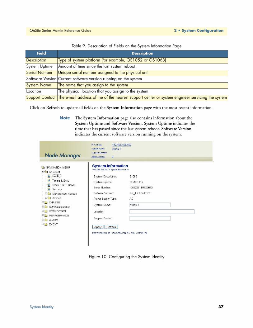
OnSite Series Admin Reference Guide 2 • System Configuration
Click on Refresh to update all fields on the System Information page with the most recent information.
Note The System Information page also contains information about the System Uptime and Software Version. System Uptime indicates the time that has passed since the last system reboot. Software Version indicates the current software version running on the system.
Figure 10. Configuring the System Identity
Table 9. Description of Fields on the System Information Page
Field Description
Description Type of system platform (for example, OS1052 or OS1063)System Uptime Amount of time since the last system rebootSerial Number Unique serial number assigned to the physical unitSoftware Version Current software version running on the systemSystem Name The name that you assign to the systemLocation The physical location that you assign to the systemSupport Contact The e-mail address of the of the nearest support center or system engineer servicing the system
System Identity 37

OnSite Series Admin Reference Guide 2 • System Configuration
Ethernet LAN Management Port SettingsThe following section provides the procedures for configuring the IP address and default gateway settings for the Ethernet LAN management port.
Configuring the Port SettingsTo configure the Ethernet LAN management (LM) port settings, see Figure 18 and follow these steps:
Note You may skip the following task if the IP address, net mask, and default gateway are already configured using the CLI, as indicated in §6.4.
1. Select the SYSTEM folder from the navigation menu.
2. From the expanded SYSTEM folder, select Management Access.
3. From the expanded Management Access folder, select LAN.
4. On the Ethernet LAN Management Port page, type the required IP Address.
Figure 11. Configuring the Ethernet LAN Management Port
Ethernet LAN Management Port Settings 38

OnSite Series Admin Reference Guide 2 • System Configuration
Changing the Default Gateway for the LAN PortTo change the default gateway for the Ethernet LAN management port, follow these steps:
Note Use this procedure to allow an NMS or a GUI client device to reach the system through the LAN port from a different IP subnet.
1. Select the SYSTEM folder from the navigation menu.
2. From the expanded SYSTEM folder, select Management Access.
3. From the expanded Management Access folder, select Routing.
4. On the Route Table page, click on Add Route.
5. On the Add New Route page, select the LM: interface using the scroll-down button.
Note LM: is the interface notation for the Ethernet LAN port.
6. Type the new default gateway on the Gateway field, and leave the rest of the fields blank.
Note The new default gateway is the IP address of the router on the IP sub-net to which the LAN port is connected. Through this router the sys-tem can access the IP subnet in which the NMS or GUI client device resides.
7. Click on Apply and then on Close to close the window.
8. Save the system configuration.
Inband Management ChannelThe system uses inband management channels (IMC) for internal IP-based communications between network elements in an OnSite OS-10 Series subnetwork. The IMC also provides a path for reaching an OS-10 Series subnetwork from a centralized OnSight NMS or GUI client device.
Note A subnetwork consists of all interconnected nodes in a point-to-point, ring, or linear network. The subnetwork may contain a mix of OS-10 Series nodes, such as the OS1052 and OS1063.
The following sections describe two methods for setting up the IMC. The first method uses the data commu-nications channel (DCC) bytes on the STM-1 signal. The second method uses an embedded E1 payload signal within a VC-12 container.
Each system has two IMC ports. The ports are designated using the following convention: IM:slot/port. IM:1/1 refers to the first inband management (IM) channel in slot 1. IMC:1/2 refers to the second IM channel in slot 1. Table 10 on page 40 provides a description of these ports.
Save the system configuration to prevent the loss of the IP settings when a system reset or reboot occurs.
CAUTION
Inband Management Channel 39

OnSite Series Admin Reference Guide 2 • System Configuration
Note The IM ports are not physical but logical ports.
SDH Data Communications Channel (DCC)The system provides the option of using the STM-1 DCC bytes for IP-based communications between OnSite OS-10 nodes in a point-to-point, ring, or linear subnetwork.
Each subnetwork has a gateway network element (GNE). All nodes in the subnetwork have IP connectivity and communicate with the OnSight NMS or GUI client device through the LAN port of the GNE.
By default, the system uses HDLC to encapsulate IP packets into the DCC bytes. The OSPF routing protocol is used to route IP packets within the subnet. The system supports an autodiscovery feature (embedded within the HDLC packets) to retrieve and display IP address information from adjacent nodes in a subnetwork.
Table 18 provides a list of the configurable options for the DCC bytes.
Note The DCCr option is the regenerator section DCC and uses the D1 to D3 bytes in the STM-1 section overhead as a 192-kbit/s channel between two systems.
Note The DCCm option is the multiplex section DCC and uses the D4 to D12 bytes in the STM-1 section overhead as a 576-kbit/s channel between two systems.
The DCC custom option allows the selection of any subset of DCC rows to form the DCC channel. You can form a custom DCC channel from four rows (see Table 12). Each row supports a 192-kbit/s channel. The sys-tem supports the creation of higher-rate DCC channels by combining two or more DCC rows into a single custom channel. For instance, you can create a custom DCC channel at 384-kbit/s by selecting any two DCC rows (for example, rows 1 and 2 or 2 and 3) or a full-rate DCC channel at 768-kbit/s by selecting all four DCC rows.
Table 10. Inband Management Channels on the OS-10 Series System
Inband Management Channel (IMC) IMC Supporting IP over . . .
IM:1/1 DCC or E1 mapped into a selected TU-12 channelIM:1/2 DCC only
Table 11. DCC Properties
Property Configurable Option
Admin Status Enabled or DisabledType DCCr, DCCm, or DCC custom
Table 12. DCC Byte Structure
Row DCC Bytes
1 D1 to D32 D4 to D63 D7 to D94 D10 to D12
Inband Management Channel 40

OnSite Series Admin Reference Guide 2 • System Configuration
The system supports a DCC transparency feature that allows unselected rows to be transferred from one STM-1 port to another. For instance, if the first DCC row (DCCr) is selected for use by STM-1 ports 1 and 2 on the base system, the remaining DCC rows (2 to 4) are transferred transparently between the two ports. The system processes IP packets from only the selected DCC rows. All other rows are relayed without processing from one STM-1 port to the other.
Note DCC transparency works between STM-1 ports on the same slot, that is, between STM-1 ports 1 and 2 on the base system (slot 1) or between ports 1 and 2 on an STM-1 expansion module (in slot 2 or 3).
The DCC transparency feature is important for applications that require interworking between OnSite OS-10 Series platforms and third-party SDH network elements on the same SDH ring or linear network. For instance, an eight-node ring may consist of two third-party SDH nodes and six OnSite nodes. If the thirdparty SDH nodes are set to process the DCCr (row 1), the OnSite nodes would be set to process the remaining DCC rows (2 to 4). This setting allows the DCCr to pass through transparently between the STM-1 ports of the OnSite nodes.
Figure 12 shows sample usage of the DCC in a four-node OS-10 ring subnetwork. In this example, the host, NMS server, and GNE LAN port reside in the same IP subnet.
Figure 12. Example of IMC Using the SDH DCC in a Ring Subnetwork
Inband Management Channel 41

OnSite Series Admin Reference Guide 2 • System Configuration
Figure 13 shows sample usage of the DCC in a point-to-point subnetwork that uses Linear 1+1 MSP protec-tion.
Figure 13. Example of IMC Using the SDH DCC in a Point-to-Point Subnetwork
To configure the IMC settings for the SDH DCC bytes, see Figure 21 and follow these steps:
Before starting the procedure, make sure that all STM-1 ports in the subnetwork are enabled (see §8.2.1) and that no alarms are present at the STM-1 RS and MS layers. In addition, make sure that the STM-1 ports of ADM nodes in a ring or linear network are connected according to the fiber interconnection procedures.
1. Select the SYSTEM folder from the navigation menu.
2. From the expanded SYSTEM folder, select Management Access.
3. From the expanded Management Access folder, select Inband Management.
4. On the Inband Management Channel page, select IM:1/1 and click on Properties.
5. In the Inband Management Channel Properties window, set the Admin Status to Enabled.
Note By default, the Admin Status for the IMC ports is set to Disabled.
6. Select the IMC Type (DCCr, DCCm, or DCC custom).
– Select the STM-1 Port from which you wish to process the DCC channel, using the scroll-down list.
If you select DCC custom, follow Step 6B to select the rows of DCC bytes that form the custom DCC chan-nel; otherwise, continue with Step 7.
– Select the rows of DCC bytes from the DCC Bytes list.
The system highlights the first row of DCC Bytes (D1 to D3) by default. You may, however, choose other rows from the list.
To select more than one row from the list, click on individual list entries while pressing the Ctrl key. (The sys-tem highlights any entry that you select from the list. You can select any entry from the list, whether the rows are contiguous or not.)
7. Type the IMC IP Address for IM:1/1.
Inband Management Channel 42

OnSite Series Admin Reference Guide 2 • System Configuration
Note Use the Reset button to cancel any recent configuration changes in the window and revert to the settings before the window was opened. The reset works only before you commit the changes using the Apply button (see Step 8).
8. Click on Apply to apply the new IMC IP settings.
9. Click on Close to close the window.
10. Repeat steps 1 through 9 for the second IMC port (IM:1/2).
Note The IMC IP addresses for IM:1/1 and IM:1/2 need to be the same.
11. Repeat Step 1 through Step 10 for all nodes in the OS-10 subnetwork.
Note Make sure that all nodes use the same set of DCC bytes (DCCr, DCCm, or DCC custom).
• Make sure that all IMC ports are in the same IP subnet.
• Make sure that the LAN and IMC ports are not in the same IP subnet.
12. Verify that all DCC links in the OS-10 subnetwork are up.
Note The Oper Status of the IMC port should change from OOS to IS when the IMC ports that define the DCC link between two nodes are operational. This change may take a few seconds. Click on Refresh to update the window with the most recent contents. You may need to refresh the window more than once while you wait for the change to occur.
Note You may use the performance statistics for the IMC as an indicator of link activity and functional verification during the initial setup proce-dure. Click on Refresh to update the window with the most recent counts.
Changing the IMC IP address settings for a node could result in the loss of management connectivity to the system if the connec-tion is currently through the IMC port.
Save the system configuration to prevent the loss of the IMC IP settings if a system reset or reboot occurs.
CAUTION
CAUTION
Inband Management Channel 43

OnSite Series Admin Reference Guide 2 • System Configuration
Figure 14. Configuring the SDH DCC
Setting Up the IP Settings for Reaching the IMC SubnetworkTo allow the OnSight NMS or GUI client device to connect with any node in the IMC subnet, you must first set a static IP route on the host or local router (see Figure 12 on page 41 and Figure 13 on page 42). The static route must point to the GNE LAN port to reach the IMC subnet.
To allow communications for all hosts and servers, have your network administrator set up a static route on your local subnet router. Alternatively, you can set a route for an individual host or server.
If your NMS server or GUI client device is a PC that supports a DOS-based operating system, follow these steps to set up a static IP route between the PC and IMC subnet:
Note Follow these steps if no local router is present on the subnet on which the host resides and you prefer to connect the host directly to the GNE LAN port.
1. Open the Command Prompt window for your operating system and type the following command:
route add aaa.bbb.ccc.ddd mask eee.fff.ggg.hhhh iii.jjj.kkk.lll
Note The address aaa.bbb.ccc.ddd is the destination network. This address is the internal IP subnet for the IMC ports.
Note The net mask eee.fff.ggg.hhh is 255.255.255.0.
Inband Management Channel 44
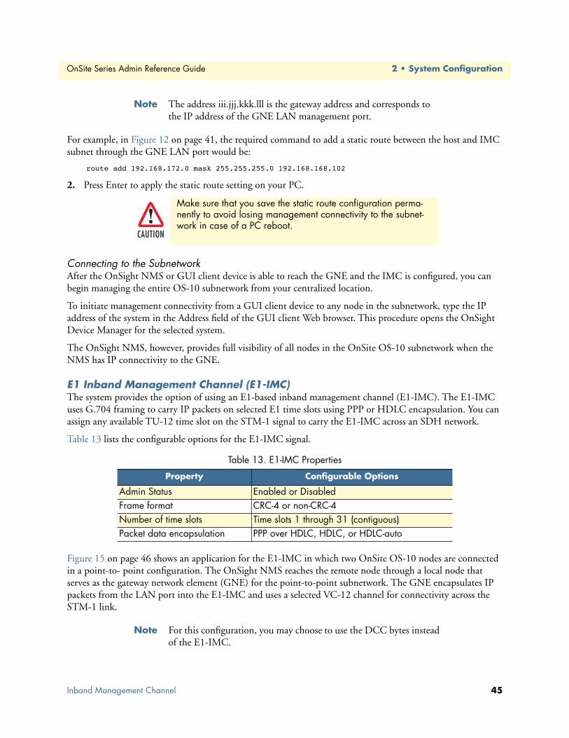
OnSite Series Admin Reference Guide 2 • System Configuration
Note The address iii.jjj.kkk.lll is the gateway address and corresponds to the IP address of the GNE LAN management port.
For example, in Figure 12 on page 41, the required command to add a static route between the host and IMC subnet through the GNE LAN port would be:
route add 192.168.172.0 mask 255.255.255.0 192.168.168.102
2. Press Enter to apply the static route setting on your PC.
Connecting to the SubnetworkAfter the OnSight NMS or GUI client device is able to reach the GNE and the IMC is configured, you can begin managing the entire OS-10 subnetwork from your centralized location.
To initiate management connectivity from a GUI client device to any node in the subnetwork, type the IP address of the system in the Address field of the GUI client Web browser. This procedure opens the OnSight Device Manager for the selected system.
The OnSight NMS, however, provides full visibility of all nodes in the OnSite OS-10 subnetwork when the NMS has IP connectivity to the GNE.
E1 Inband Management Channel (E1-IMC)The system provides the option of using an E1-based inband management channel (E1-IMC). The E1-IMC uses G.704 framing to carry IP packets on selected E1 time slots using PPP or HDLC encapsulation. You can assign any available TU-12 time slot on the STM-1 signal to carry the E1-IMC across an SDH network.
Table 13 lists the configurable options for the E1-IMC signal.
Figure 15 on page 46 shows an application for the E1-IMC in which two OnSite OS-10 nodes are connected in a point-to- point configuration. The OnSight NMS reaches the remote node through a local node that serves as the gateway network element (GNE) for the point-to-point subnetwork. The GNE encapsulates IP packets from the LAN port into the E1-IMC and uses a selected VC-12 channel for connectivity across the STM-1 link.
Note For this configuration, you may choose to use the DCC bytes instead of the E1-IMC.
Make sure that you save the static route configuration perma-nently to avoid losing management connectivity to the subnet-work in case of a PC reboot.
Table 13. E1-IMC Properties
Property Configurable Options
Admin Status Enabled or DisabledFrame format CRC-4 or non-CRC-4Number of time slots Time slots 1 through 31 (contiguous)Packet data encapsulation PPP over HDLC, HDLC, or HDLC-auto
CAUTION
Inband Management Channel 45

OnSite Series Admin Reference Guide 2 • System Configuration
Figure 15. E1-IMC Application 1: Direct Point-to-Point
Figure 16 shows another application for the E1-IMC in which two OnSite OS-10 nodes are connected in a point-to-point configuration across a third-party SDH network. The OnSight NMS reaches the remote node through the GNE. The GNE encapsulates IP packets from the LAN port into the E1-IMC and uses a selected VC-12 channel to connect the IMC transparently across the SDH cloud.
Figure 16. E1-IMC Application 2: Point-to-Point Across SDH Network
Configuring the E1-IMC SettingsTo configure the E1-based IMC settings, see Figure 24 and follow these steps:
1. Select the SYSTEM folder from the navigation menu.
2. From the expanded SYSTEM folder, select Management Access.
3. From the expanded Management Access folder, select Inband Management.
4. On the Inband Management Channel page, select IM:1/1 and click on Properties.
Note Only IM:1/1 can be set for operation as an E1-IMC.
5. In the Inband Management Channel Properties window, set Admin Status to Enabled.
Inband Management Channel 46

OnSite Series Admin Reference Guide 2 • System Configuration
Note By default, the Admin Status for the IMC ports is set to Disabled.
6. Set the IMC Type to E1-IMC.
7. Type the IMC IP Address for the E1-IMC port.
8. Select the E1 Frame Format (CRC-4 or non-CRC-4)
Note By default, the system uses the CRC-4 framing format. Time slot 0 is set according to the selected G.704 E1 frame format (whether CRC-4 or non-CRC-4). Make sure that frame format is the same on both sides of the E1-IMC link.
9. Type the E1 Time Slots (1 to 31).
Note By default, the system uses E1 time slots 1 through 31 for carrying payload data. You may use a reduced number of time slots for carry-ing payload data; however, make sure that the time slot setting is the same on both sides of the E1-IMC link.
10. Select the Encapsulation method (PPP/HDLC, HDLC, or HDLC-auto).
Note PPP/HDLC means PPP over HDLC.
Note Use HDLC (Auto) when connecting two OS-10 systems directly in a point-to-point configuration. This encapsulation method enables autodiscovery and retrieval of the IP address for the remote system.
11. If you do not use HDLC-auto as the encapsulation method, type the Remote IP Address for the E1-IMC on the adjacent OS-10 node.
Note The system fills this address field automatically when the encapsula-tion method is set to HDLC (Auto).
12. Select the TU-12 time slot location of the VC-12 that carries the E1-IMC signal, using the TU-12 Loca-tion scroll-down button.
Note The scroll-down list displays only the TU-12 time slot locations that remain available.
Note Make sure that the GNE and remote node use the same TU-12 time slot location for the E1-IMC.
13. Click on Apply to apply the new IMC IP settings.
Changing the IP address, net mask, and default gateway settings for the IMC could result in the loss-of-management connectivity to the system, if the connection is currently through the IMC port.
CAUTION
Inband Management Channel 47

OnSite Series Admin Reference Guide 2 • System Configuration
14. Click on Close to close the window.
15. Repeat Step 1 through Step 13 for both nodes.
Note Make sure that both nodes use the same frame format, time slots, and encapsulation.
• Make sure that the IMC ports on both nodes are in the same IP subnet.
• Make sure that the LAN and IMC ports are not in the same IP subnet.
16. Verify that the E1-IMC link between the two nodes is up.
Note The Oper Status of the IMC port should change from OOS to IS when the IMC ports that define the E1-IMC link between two nodes are operational. This change may take a few seconds. Click on Refresh to update the window with the most recent contents. You may need to refresh the window more than once while you wait for the change to occur.
Note You may use the performance statistics for the IMC as an indicator of link activity and functional verification during the initial setup proce-dure. Click on Refresh to update the window with the most recent counts.
Save the system configuration to prevent the loss of the IMC IP settings if a system reset or reboot occurs.
CAUTION
Inband Management Channel 48

OnSite Series Admin Reference Guide 2 • System Configuration
Figure 17. Configuring the E1 Inband Management Channel
Configuring a Default Gateway for the E1-IMCIf you do not use HDLC (Auto) as the encapsulation method, you must also set the default gateway route for the E1-IMC port on the remote OS-10 node. The new default gateway for this port should be set to the IP address of the E1-IMC port on the GNE.
To change the default gateway for the E1-IMC port on the remote node, follow these steps:
1. Select the SYSTEM folder from the navigation menu.
2. From the expanded SYSTEM folder, select Management Access.
3. From the expanded Management Access folder, select Routing.
4. On the Route Table page, click on Add Route.
5. On the Add New Route page, select the IM:1/1 interface using the scroll-down button.
6. Type the new default gateway on the Gateway field, and leave the rest of the fields blank.
Note The new default gateway is the IP address of the E1-IMC port on the GNE.
Note For example, in Figure 25, the required settings for changing the default gateway for theE1-IMC on the remote node would be as fol-lows: Destination is 0.0.0.0, Mask is 0.0.0.0, and Gateway is 192.168.172.102.
Inband Management Channel 49

OnSite Series Admin Reference Guide 2 • System Configuration
7. Click on Apply and then on Close to close the window.
8. Save the system configuration.
Figure 18. Example of Using the E1-IMC in a Point-to-Point Subnetwork
Monitoring the E1-IMC Alarms and PerformanceThe system monitors the following E1 path defects associated with the E1-IMC:
• AIS (alarm indication signal)
• LFA (loss of frame alignment), according to G.706
• RDI (remote defect indicator using the A bit), according to G.704
To display E1-IMC alarms, if present, follow these steps:
1. Select the ALARM folder from the navigation menu.
2. From the expanded ALARM folder, select Show Active Alarms.
At this point, the Active Alarms page displays all active alarms in the system, including E1-IMC alarms, if present. The table contains a separate entry for each active E1-IMC alarm. Table 14 describes the fields for each E1-IMC alarm entry.
Save the system configuration to prevent the loss of the IP settings if a system reset or reboot occurs.
Table 14. Table Entries for Active E1-IMC Alarms
Table Entry for Active Alarms Field Value
Type E1 AIS, E1 LFA, or E1 RDIAlarm Raised Time Date and time
Severity Critical, Major, Minor, or WarningDetailed Information Location of affected inband management channel (IM:1/1)
CAUTION
Inband Management Channel 50

OnSite Series Admin Reference Guide 2 • System Configuration
Note The system automatically updates the Active Alarms page every 60 seconds. Click on Refresh if you need to update the table with the most recent active alarm information. Individual table entries auto-matically clear whenever previously active alarms are no longer present.
The system calculates the following E1 path error performance events, as listed in Table 15, for the E1-IMC in accordance with Recommendations G.826 and G.829:
Note A period of unavailable time begins at the onset of 10 consecutive SES seconds. These 10 seconds are part of unavailable time. A period of available time begins at the onset of 10 consecutive non-SES sec-onds. These 10 seconds are part of available time.
To display current and historical PM data for the E1-IMC, follow these steps:
1. Select the PERFORMANCE folder from the navigation menu.
2. From the expanded PERFORMANCE folder, select Counters.
3. From the expanded Counters folder, select Inband Management.
At this point, the Inband E1 Near-end PM – Current 15 minutes page shows the near-end PM data for the current 15-minute period only.
Note The PM data is not updated automatically as new events occur dur-ing the Current 15-minute and 24-hour periods. Click on Refresh to update the tables with the most recent cumulative count for the cur-rent periods.
Continue with the step that follows to display historical PM data for both 15-minute and 24-hour periods.
4. Select the table entry for the IM:1/1 port and click on Show Interval.
Note The tables display Invalid under PM data when the data collected during a measurement period is considered invalid. Interval Start Time also displays n/a (not available).
Table 15. E1 Path Error Performance Events for the E1-IMC
PM Parameter Description Definition
BBE Background Block Error An EB (errored block) not part of an SESES Errored Second A second containing at least one EB or a defect (LFA or AIS)SES Severely Errored Second A second containing K or more EBs or a defect (LFA or AIS)UAS Unavailable Second A period of unavailable time that begins at the onset of 10
consecutive SES
Inband Management Channel 51

OnSite Series Admin Reference Guide 2 • System Configuration
Timing and SynchronizationThe system supports two timing modes: Internal and Auto. Table 16 describes these modes.
Note The default timing mode at power up is Internal,
Note The internal system clock is of Stratum 3 (± 4.6 ppm) quality.
To display the type of clock installed in your system, follow these steps:
1. Select the CHASSIS folder from the navigation menu.
2. From the expanded CHASSIS folder, select Slots.
3. Select the table entry for Slot ID number 1 (the base system) and click on Properties.
The Stratum Type field indicates the stratum quality of the system clock (Stratum 3).
Auto Mode OperationIn Auto mode, the system remains in the initial free-run state until a valid timing source becomes available on either the primary or secondary reference source. You can select the primary and secondary sources from several reference input candidates. Table 17 summarizes the available sources.
Note If the OS1052 is equipped with T1 interfaces on the base system, the second reference pair is T1 port 7 and port 8. For an OS1063 with T1 interfaces on the base system, the second reference pair is T1 ports 20 and 21. The system uses the incoming 1.544-MHz clock when these T1 ports are configured as Sync In.
Note If the system is equipped with HD-E1 expansion modules, the system presents additional timing reference pair options using E1 ports 20 and 21 on those modules.
Table 16. System Timing Modes
Timing Mode Description
Internal The system is synchronized to the internal oscillator. This mode is also known as forced free-run.
Auto The system is synchronized using one or two timing reference sources.These sources are designated as the primary and secondary sources.
Table 17. Timing References for Synchronization in Auto Mode
Reference Primary Secondary Timing Mode Timing Source
Pair 1 STM-1 port 1 STM-1 port 2 Line timing Derived clock from STM-1 linePair 2 E1 port 7
(OS1052)E1 port 20(OS1063)
E1 port 8(OS1052)E1 port 21(OS1063)
Line timing Derived clock from E1 line when both E1 ports are configured to carry traffic
External timing Incoming 2.048-MHz clock when both E1 ports are configured as Sync In
Timing and Synchronization 52

OnSite Series Admin Reference Guide 2 • System Configuration
If both timing references are available, the system uses the primary reference as the active source and the sec-ondary as the standby source.
In Auto mode, the system can be in one of three states, as listed in Table 18:
If the primary reference fails, the system automatically switches to the secondary reference in a hitless manner. The switchover does not occur if either a “Lockout” or a “Forced to Primary” external command is present. The system considers an input timing reference as unavailable according to the criteria in Table 19.
The system reports an alarm condition when the primary or secondary reference fails.
Note In Holdover state, the Stratum 3 clock has the following characteris-tics: ± 0.37 ppm for the first 24 hours.
To configure the system timing mode, see Figure 19 on page 55 and follow these steps:
1. Select the SYSTEM folder from the navigation menu.
2. From the expanded SYSTEM folder, select Timing & Sync.
3. On the Timing & Synchronization page, select one of the Timing Mode – Primary/Secondary Source options using the scroll-down button.
Note By default, Timing Mode – Primary/Secondary Source is set to Internal. In this mode, the system uses the local internal oscillator as the sole source of timing.
Choose Auto: STM-1 port 1/1, port 1/2 for operation in Auto mode, using the derived clock from STM-1 ports 1 and 2 as the primary and secondary references, respectively.
Table 18. Timing States
Timing State Description
Free-run This state is the initial state until a valid timing reference becomes available.Normal The system is locked to either the primary or secondary reference.Holdover The system was previously in the Normal state, and both the primary and secondary refer-
ences are unavailable. This state also occurs if the primary reference is unavailable, the secondary reference is available, and either a “Lockout” or “Forced to Primary” external command is present. The system reverts from the Holdover to the Normal state when either the primary or secondary reference becomes available.
Table 19. Criteria for Declaring an Input Timing Reference as Unavailable
Internal Clock Input Timing Reference Is Unavailable when the . . .
Stratum 3 option STM-1 signal is in LOS, LOF, or MS-AIS condition; or the incoming SSM code is DNU or invalid; or the E1 signal is in LOS conditionFrequency is off by ± 12 ppm from nominal
Timing and Synchronization 53

OnSite Series Admin Reference Guide 2 • System Configuration
Note If the system is configured for operation with a single unprotected STM-1 port, the system can still operate in Auto mode but with one of the two references always unavailable.
Choose Auto: STM-1 port 1/1 only for operation in Auto mode, using the derived clock from STM-1 port 1 as the only timing source for the system. With this setting, the system goes inmmediately into holdover mode when STM-1 port 1 becomes unavailable as a timing reference.
Note This timing mode must be used for proper operation of OS-10 nodes in a 2-fiber (unprotected) linear ADM topology. All subtending OS-10 nodes in a linear ADM chain must be synchronized to the Mas-ter/Headend node using this timing source selection. Also, all sub-tending nodes in the chain must be configured with the Synchronization Status Messages (SSM) set to Disabled (see Figure 19 on page 55).
Note The linear ADM chain must start from STM-1 port 1/2 on the Hea-dend node. This port should be connected to STM-1 port 1/1 of the first subtending OS-10 node in the chain and port 1/2 of this node should be connected to port 1/1 of the next node in the chain. All nodes in the chain must be connected to each other in like manner.
Choose Auto: E1 port 1/7, port 1/8 in the OS1052 (or Auto: E1 port 1/20, port 1/21 in the OS1063) for operation in Auto mode using the derived clock from E1 ports 7 and 8 in the OS1052 (or E1 ports 20 and 21 in the OS1063) as the primary and secondary references, respectively.
Note If only one E1 port is configured as Sync In, the system can still oper-ate in Auto mode but with one of the two references always unavail-able.
4. Click on Apply for the settings to take effect.
When Auto mode is selected, Timing Status on the Timing & Synchronization page changes from Free-run to Normal if the system is able to lock to one of the two timing references. Later, if no reference is available, Timing Status changes to Holdover.
Check Primary Reference Status and Secondary Reference Status to see the current status for each of the tim-ing references. If the reference is available, the status indicator shows whether the reference is active or standby. For example, if the primary reference is available and the system is locked to this reference, the status indicator for this reference shows “active.” If the secondary reference is also available, the status indicator shows “standby” for this reference. The status indicator also shows the incoming synchronization status message (SSM) code for available references if the use of SSM codes is enabled.
Operation Status on the Timing & Synchronization page indicates Normal when both the primary and sec-ondary references are available, with one reference active and the other in standby mode. Operation Status indicates Unavailable reference when one or both references are unavailable and either a “Lockout” or “Forced to Primary” external command is present.
Click on Refresh to update the page with the most current status information.
Timing and Synchronization 54

OnSite Series Admin Reference Guide 2 • System Configuration
NOTE: The system does not allow changing the timing mode directly from Auto: STM-1 port 1/1, port 1/2 to Auto: E1 port 1/7, port 1/8 in the OS1052 (or Auto: E1 port 1/20, E1 port 1/21 in the OS1063). You must first change the timing mode to Internal and then to Auto: E1 port 1/7, port 1/8 (or Auto: E1 port 1/20, port 1/21).
Figure 19. Configuring the System Timing Mode
The system supports two types of switch operation for timing references: revertive and non-revertive.Table 20 describes these operations.
To configure the switch operation type, see figure 19 and follow these steps:
1. Select the SYSTEM folder from the navigation menu.
2. From the expanded SYSTEM folder, select Timing & Sync.
3. On the Timing & Synchronization page, select one of the Switch Operation Type options: Non-rever-tive or Revertive.
Table 20. Switch Operation Types for Timing
Operation Type The System . . .
Revertive Switches back to the primary reference after the primary reference becomes avail-able. The system waits for a preset amount of time (that is, the wait-to-restore time) before the switchover from the secondary to the primary reference occurs.
Non-revertive Stays locked to the secondary reference even after the primary reference becomes available. A switchover back to the primary reference either occurs after comple-tion of an external switch command (forced or manual) or after recovery of the pri-mary reference and subsequent failure of the secondary reference.
Timing and Synchronization 55

OnSite Series Admin Reference Guide 2 • System Configuration
Note By default, Switch Operation Type is set to Non-revertive.
To change the wait-to-restore time, continue with Step 4; otherwise, go directly to Step 5 to complete this task.
Note The wait-to-restore time is applicable only when using revertive switching. Its value is ignored when using non-revertive switching.
4. On the Timing & Synchronization page, change Wait-To-Restore Time from the factory default setting of 5 (minutes) to any integer value between 0 and 12 minutes.
5. Click on Apply for the settings to take effect.
When revertive mode is selected, Operation Status on the Timing & Synchronization page indicates Wait-to-Restore (WTR) after a timing reference switchover has occurred and the system is waiting to switch back to the primary reference after completion of the WTR time.
External Commands for Timing Reference SwitchingThe system allows the use of external commands to switch between the Primary and Secondary references. Table 21 lists the external commands that the system supports:
To activate any of the external commands for timing reference switching, see Figure 20 on page 57 and follow these steps:
1. Select the SYSTEM folder from the navigation menu.
2. From the expanded SYSTEM folder, select Timing & Sync.
Table 21. External Commands for Timing Reference Switching
Priority Command Action Completion
1 Clear Clears all switch commands Always2 Lockout Disables a switch to the second-
ary referenceAlways
3 Forced to Secondary Switches from the primary to the secondary reference
Denied if the invalid signal condition is present on the secondary refer-ence or if the Lockout command is present
Forced to Primary Switches from the secondary to the primary reference
Denied if the Lockout command is present
4a
a. Manual switching is hitless.
Manual to Secondary Switches from the primary to the secondary reference
Denied if the invalid signal condition is present on the secondary refer-ence or if the Lockout or Forced com-mand is present
Manual to Primary Switches from the secondary to the primary reference
Denied if the invalid signal condition is present on the primary reference or if the Lockout or Forced command is present
Timing and Synchronization 56

OnSite Series Admin Reference Guide 2 • System Configuration
3. On the Timing & Synchronization page, select one of the Command options in Table 21 on page 56.
Note By default, Command is set to No Command.
4. Click on Initiate Command to activate the external command.
Note Use external commands only when system operation is in Auto tim-ing mode.
5. To reset any active command, select the Clear command option and click on Initiate Command. Other-wise, the current command remains active until a higher priority command is issued or a failure event occurs (see Table 21).
Operation Status on the Timing & Synchronization page indicates Manual, Forced, or Lockout when an external command is active.
Figure 20. Configuring the External Commands for Switching Timing References
Timing and Synchronization 57

OnSite Series Admin Reference Guide 2 • System Configuration
S1-Byte SupportThe system generates and uses the synchronization status message (SSM) codes and quality levels for “Option I SDH synchronization networking” in G.781, as shown in Table 22.
Note The system uses the code for SSU-B for Stratum 3 systems in free-run mode.
The system rejects an incoming STM-1 port as a timing reference source (that is, the system considers the ref-erence as unavailable) if the incoming SSM for the port has the DNU code.
To enable the use of the SSM, see Figure 26 and follow these steps:
1. Select the SYSTEM folder from the navigation menu.
2. From the expanded SYSTEM folder, select Timing & Sync.
3. On the Timing & Synchronization page, set Synchronization Status Messages (SSM) to Enabled.
4. Click on Apply to complete this task.
Note The Timing & Synchronization page (see Figure 19 on page 55) shows the Sync Quality Level for the primary and secondary timing reference sources. The system translates the incoming SSM code into the equivalent Sync Quality Level for the source.
External SynchronizationYou can configure E1 ports 7 and 8 in the base OS1052 system (or E1 ports 20 and 21 in the base OS1063 sys-tem) individually in one of three modes:
• Traffic
• Synchronization input (Sync In)
• Synchronization output (Sync Out)
By default, the system uses E1 ports 7 and 8 in the base OS1052 system (or E1 ports 20 and 21 in the base OS1063 system) for carrying regular E1 traffic. When the ports carry E1 traffic and the timing mode is set to Auto: E1 port 1/7, port 1/8 in the OS1052 (or Auto: E1 port 1/20, port 1/21 in the OS1063), the system uses the derived clock from these ports as the primary and secondary references for the system.
When these ports are configured in Sync In mode and the timing mode is set to Auto, the system uses external timing input signals at 2.048 MHz as the primary and secondary references for the system. The external timing inputs do no carry traffic and comply with the physical layer specifications in G.703 for external 2.048-MHz synchronization signals.
Table 22. SSM Codes and Quality Levels Supported on the OS-10
Quality Level SSM COde (S1 Bits 5-8)
PRC 0010SSU-A 0100SSU-B 1000SEC 1011DNU 1111
Timing and Synchronization 58

OnSite Series Admin Reference Guide 2 • System Configuration
Note In Sync Out mode, the E1 port requires the use of an external 3dB attenuator to bring the voltage level for the 2.048 MHz synchroniza-tion signal down to the required level in G.703.
When the system is synchronized to external timing inputs using the Sync In ports, the system generates the SSM codes (see Table 29) in accordance to the quality level that you assign to these ports. The quality level should be set in accordance to the quality of the timing source that generates the 2.048-MHz signals. For example, if the system receives timing from an SSU-A (or BITS) clock through the E1 Sync In ports, you should set the quality level of the E1 Sync In ports to SSU-A.
When either E1 port 7 or E1 port 8 in the OS1052 (or E1 port 20 or port 21 in the OS1063) is configured in Sync Out mode, the system generates a G.703-compliant synchronization signal at 2.048 MHz. With this set-ting, it is not possible to set the timing mode to Auto using these ports.
Sync Out SquelchingThe system provides the option of squelching the Sync Out ports. The squelching function turns off the trans-mitter of the Sync Out ports when the timing mode changes to Internal or the system enters into the Free-run state. The system removes the squelching when locked again to either the primary or secondary reference.
Clock and NTP ServerThe system supports the ability to obtain real-time clock (RTC) information from a network time protocol (NTP) server. The clock information is used for time-stamping when required.
The system also allows manual configuration of the clock whenever access to an NTP server is not possible.
To configure the system date and time with an NTP server, see Figure 21 on page 60 and follow these steps:
1. Select the SYSTEM folder from the navigation menu.
2. From the expanded SYSTEM folder, select Clock & NTP Server.
3. On the System Clock page, set NTP Services to Enabled.
Note By default, NTP Services is set to Disabled.
4. Type the IP address for NTP Server 1 and for NTP Server 2, if required.
5. Click on Apply to initiate connectivity to the NTP servers.
At this point, NTP State changes to NTPD running when the system finds and updates the system clock using one of the NTP servers.
Click on Refresh to retrieve the most current NTP State and System Current Time.
Note The system maintains the date and time settings for up to 8 hours after power is removed from the system.
Clock and NTP Server 59

OnSite Series Admin Reference Guide 2 • System Configuration
Figure 21. Configuring Access to an NTP Server
To configure the system clock manually, follow these steps:
1. Select the SYSTEM folder from the navigation menu.
2. From the expanded SYSTEM folder, select Clock & NTP Server.
3. On the System Clock page, set NTP Services to Disabled.
4. To modify the local time zone, use the Time Zone scroll-down button to select the new time zone and click on Apply. Go directly to Step 7 if the current setting for the time zone is correct.
Note The factory default for the time zone is GMT (Greenwich Meridian Time, also known as Coordinated Universal Time). The system auto-matically adjusts the current time according to the daylight saving time requirements for your time zone, when needed.
5. Save the system configuration to prevent the loss of the new time zone setting when the system reboots.
6. Reboot the system to apply the new time zone settings. (After completion of the reboot, repeat Step 1 and Step 2, and continue with Step 7).
7. Type the System Current Time in the specified format (yyyy/mm/dd hh:mm:ss).
Note The time format includes the year (yyyy), month (mm) and day (dd), and the hour (hh), minutes (mm) and seconds (ss). The hour is in 24-hour format.
8. Click on Apply to put the new current time into effect.
Clock and NTP Server 60

OnSite Series Admin Reference Guide 2 • System Configuration
SecurityThe system supports three types of users, as shown in Table 23:
Note The factory-assigned default password for the Super user is super (all lowercase letters). The Super user can change his or her and can also reset the password of Admin and Monitor users to the factory-assigned default. The Super user can also change the Admin or Moni-tor user password to any valid alphanumeric string if required.
• The factory-assigned default password for an Admin user is admin (all lowercase letters). An Admin user cannot change his or her password.
• The factory-assigned default password for a Monitor user is moni-tor (all lowercase letters). A Monitor user cannot change his or her password.
• For all user types, the password must be 5 to 12 characters in length, and can contain only the following alphanumeric charac-ters: lower case letters (a through z), upper case letters (A through Z), numbers (0 through 9), hyphens (-), commas (,), colons (:),underscores (_), slashes (/), periods (.), spaces, parentheses, and the @ character.
To change the user password, follow these steps:
Note The following procedure only applies to the Super user. The system denies this operation for Admin and Monitor users.
1. Select the SYSTEM folder from the navigation menu.
2. From the expanded SYSTEM folder, select Security.
3. From the expanded Security folder, select Manage User.
Table 23. User Types and Privileges
User Type This User Type Permits . . .
Super Read and write operations on all items. The Super user can set up and manage IP addresses, user accounts, and passwords. Only one Super user can exist.
Admin Read and write operations on most items. The Admin user cannot set up user accounts, and passwords.
Monitor Read-only operations.
If the Super user wishes to access the system but forgets his or her pass-word, it is necessary to restore the system to the factory default settings.
WARNING
Security 61

OnSite Series Admin Reference Guide 2 • System Configuration
4. On the User Management page, select the user for which you wish to change the password and click on Change Password.
5. In the Change Password window, type the New Password, and Confirm Password fields.
6. Click on Apply for the new password to be in effect and then on Close to close the window.
Note For Admin and Monitor users, contact the Super user if you forget the password.
To reset a password back to factory default, follow these steps:
Note The following procedure only applies to the Super user. The system denies this operation for Admin and Monitor users.
1. Select the SYSTEM folder from the navigation menu.
2. From the expanded SYSTEM folder, select Security.
3. From the expanded Security folder, select Manage User.
4. On the User Management page, select the user for which you wish to reset the password and click on Reset Password to Default.
System ActionsThis section includes procedures for the downloading and upgrading of the system software. It also includes procedures for initiating a system reset and saving the current system configuration. The section ends with pro-cedures for restoring the system to the factory default configuration and instructions for transferring the system configuration and log files to and from a server.
Downloading System SoftwareThe system allows the downloading and installation of new software images from local or remote locations using FTP or TFTP. The OS-10 system flash memory contains two partitions for the software image: Active and Standby. Table 24 describes each memory partition.
To download and install software into the Standby memory partition, see Figure 22 on page 64 and follow these steps:
1. Select the SYSTEM folder from the navigation menu.
2. From the expanded SYSTEM folder, select the Actions folder.
Table 24. Software Image Memory Partitions
Memory Partition Contains the . . .
Active Current software image. The system uses this image to boot and run its operating system and applications.
Standby Standby software image. This image may differ from the image in the Active parti-tion. The software downloading process places the new Standby software image. This image may differ from the image in the Active partition. The software down-loading process places the new
System Actions 62

OnSite Series Admin Reference Guide 2 • System Configuration
3. From the expanded Actions folder, select Download Software.
4. On the Download and Install Software Image for Upgrade page, set Transfer Protocol to FTP or TFTP.
Note FTP is the default transfer protocol. FTP and TFTP work on Win-dows, UNIX, and Linux servers.
5. Type the Host Pathname to indicate the name of the software image file to be retrieved and its location within the host server.
Note You must specify either the full pathname or the relative pathname from the server root directory to indicate the location of the software image file. The file name for the software image must contain the .img extension.
6. Type the Server IP Address of the host server containing the software image file.
7. Type the User Name and Password for secure access to the file.
Note In this step, you must enter the user name and password, as demanded by the server access permission.
8. Click on Download to initiate the file transfer between the server and OS-10 system.
Note The software downloading process takes a few minutes to complete. The system continues normal operation while the downloading pro-cess takes place.
• A progress window indicates the percentage of completion. Click on Cancel to terminate the file transfer process at any time.
• The interruption of the file transfer process causes corruption of the software image in the Standby partition. The system does not allow the selection of the Standby image for system bootup if the file is corrupted.
System Actions 63

OnSite Series Admin Reference Guide 2 • System Configuration
Figure 22. Downloading and Installing the System Software
Upgrading System SoftwareTo upgrade the system software from the current image in the Active memory partition to the image in the Standby memory partition, see Figure 23 on page 65 and follow these steps:
1. Select the SYSTEM folder from the navigation menu.
2. From the expanded SYSTEM folder, select the Actions folder.
3. From the expanded Actions folder, select Upgrade Software.
4. On the Software Image Upgrade page, select Image Source for Next Reboot using the scrolldown button.
Note The system displays No image installed (standby) if no image is present in the Standby partition.
5. Click on Apply to confirm the selection of the new image and begin the system reboot process.
At this point, the system begins the reboot process using the software image in the Image Source for Next Reboot field.
This action initiates a cold reboot if the new image contains firm-ware changes; otherwise, the system begins a warm reboot pro-cess. A warm reboot does not result in traffic interruption while the reboot process takes place. Consult your software release notes to see if installation of the new image results in either a warm or cold reboot.
CAUTION
System Actions 64

OnSite Series Admin Reference Guide 2 • System Configuration
Figure 23. Upgrading the System Software
A cold reboot results in traffic interruption while the reboot process takes place. Make sure that you first save the system configuration to the flash memory to prevent the loss of configuration data. The system uses the last saved configuration to restore system operation and traffic connectivity after the completion of the reboot. Any recent configuration data and connections not saved to the system configuration file are lost and need reentry, if required.
WARNING
System Actions 65

OnSite Series Admin Reference Guide 2 • System Configuration
Resetting the SystemThe system supports two types of reset: warm reset and cold reset. To reset the system using the Webbased management interface, follow these steps:
1. Select the SYSTEM folder from the navigation menu.
2. From the expanded SYSTEM folder, select the Actions folder.
3. From the expanded Actions folder, select Reset System.
4. On the System Reset page, click on Warm Reset to reset the system using a warm reboot. Alternatively, to reset the system using a cold reboot, click on Cold Reset.
A warning window opens to alert you to the start of the system reset process using a warm or cold reboot. Click on OK to continue or Cancel to cancel the request.
Note A warm reboot does not result in traffic interruption while the reboot process takes place.
Note Another way to cause the system to reset and reboot is to initiate a power cycle. A power cycle occurs when you turn off the system and then turn it back on. For systems using AC power, use the on-off switch on the rear panel. For systems using DC power, use the on-off switch on the circuit breaker or rectifier unit that supplies power to the system.
A cold reboot results in traffic interruption while the reboot process takes place. Make sure that you first save the system configuration to the flash memory to prevent the loss of configuration data. The system uses the last saved configuration to restore system operation and traffic connectivity after the completion of the reboot. Any recent configuration data and connections not saved to the system configuration file are lost and need reentry, if required.
After turning off the AC power switch, wait for at least 3 seconds before turning it back to the on position.
Do not touch the DC power contacts on the front panel when power is applied to the system.
WARNING
CAUTION
WARNING
System Actions 66

OnSite Series Admin Reference Guide 2 • System Configuration
Saving the System ConfigurationTo save the system configuration to the flash memory, follow these steps:
1. Select the SYSTEM folder from the navigation menu.
2. From the expanded SYSTEM folder, select the Actions folder.
3. From the expanded Actions folder, select Save Configuration.
4. On the Save Configuration page, click on Save Configuration.
A warning window opens to alert you to the start of the save-configuration process. Click on OK to continue or Cancel to cancel the request.
Restoring the Factory Default SettingsTo restore the factory default settings for the system, follow these steps:
1. Select the SYSTEM folder from the navigation menu.
2. From the expanded SYSTEM folder, select the Actions folder.
3. From the expanded Actions folder, select Restore Factory Default.
4. On the Reset Configuration to Factory Default page, click on Reset Configuration to Factory Default.
A warning window opens to alert you to the start of the restore-factory-default process. Click on OK to con-tinue or Cancel to cancel the request.
This action causes the system to overwrite the current configuration data stored in the flash memory. The system uses the last saved configuration to restore system operation and traffic connectivity after the completion of a reboot. Any recent configuration data and connections not saved to the sys-tem configuration file are lost and need re-entry, if required.
This action causes the system to overwrite the current configuration data stored in the flash memory with the original factory default settings and causes the system to perform a cold reboot. This reboot causes the permanent deletion of all current connections and custom configuration options. In addi-tion, you may lose management connectivity to the system when the IP addresses of the management ports revert to factory default.
WARNING
WARNING
System Actions 67

OnSite Series Admin Reference Guide 2 • System Configuration
Transferring the System Configuration FileTo transfer the system configuration file between an FTP/TFTP server and the system, see Figure 24 on page 69 and follow these steps:
Note The system configuration file is a binary file and is not user readable. When you upload the configuration file to a host server, the file is tied to the serial number of the system. The system does not allow the downloading of a configuration file that does not match the serial number of the system.
1. Select the SYSTEM folder from the navigation menu.
2. From the expanded SYSTEM folder, select the Actions folder.
3. From the expanded Actions folder, select Transfer Configuration File.
4. On the Transfer Configuration File page, set the Transfer Protocol to FTP or TFTP.
Note FTP is the default transfer protocol. FTP and TFTP work on Win-dows, UNIX, and Linux servers.
5. Set Transfer Action to Download or Upload.
Note Use Upload if you wish to transfer the configuration file on the OS-10 to the FTP/TFTP server. Use Dowload, however, to transfer the file in the opposite direction – from the server to the OS-10.
6. Type the Host Pathname to indicate the name that you will give to the OS-10 configuration file and the location of this file within the host computer where the FTP/TFTP server resides.
Note You must specify either the full pathname or the pathname relative to the FTP/TFTP server root directory to indicate the location of the configuration file. When uploading the configuration file, the config-uration file that resides on the OS-10 will be transferred and placed in the specified Host Pathname location. In the opposite direction – when downloading the configuration file into the OS-10, the config-uration file that resides on the OS-10 will be replaced with the con-figuration file on the Host Pathname location.
Note The configuration file must not contain spaces. You can use hyphen (-) or undercore (_) instead of spaces. The configuration file name need not have any extension but it is recommended that you use the .cfg extension for ease of reference. It is also recommended that that the file name includes information such as the system name and the date the configuration file was last saved.
7. Type the Server IP Address of the host computer on which the FTP/TFTP server resides.
System Actions 68

OnSite Series Admin Reference Guide 2 • System Configuration
8. Type the User Name and Password for secure access to the file. In this step, you must enter the user name and password, as demanded by the FTP server access permission. (If you use TFTP, the user name and password are not required and should be left empty.)
9. Click on Apply to initiate the file transfer between the server and OS-10 system.
Note The file transfer process may take from a few seconds to one or two minutes to complete, depending on the size of the file. The system continues normal operation while the downloading process takes place.
• A progress window indicates the percentage of completion. Click on Cancel to terminate the file transfer process at any moment.
• Transfer Result on the Transfer Configuration File page indicates the status of the file transfer; that is, whether the transfer is still in progress or has been completed.
• The interruption of a download-file-transfer process causes corrup-tion of the configuration file.
Figure 24. Transferring the System Configuration File
System Actions 69

OnSite Series Admin Reference Guide 2 • System Configuration
Uploading the System Log FileThe system log file contains historical information on system-related activities. This file is for diagnostic pur-poses only.
Note The system log file is an ASCII file and is user readable. The log file, however, is intended for use by system engineers or trained personnel servicing the OS-10 system.
To upload the system log file into a host server, see Figure 25 on page 71 and follow these steps:
1. Select the SYSTEM folder from the navigation menu.
2. From the expanded SYSTEM folder, select the Actions folder.
3. From the expanded Actions folder, select Upload Log File.
4. On the Upload Log File page, set Transfer Protocol to FTP or TFTP.
Note FTP is the default transfer protocol. FTP and TFTP work on Win-dows, UNIX, and Linux servers.
5. Type the Host Pathname to indicate the name of the system log file and its target directory within the host server.
Note You must specify either the full pathname or the pathname relative to the server root directory to indicate the location of the log file. The log file name need not have any extension but it is recommended that you use the .log extension for ease of reference. It is also recom-mended that that the file name includes information such as the sys-tem name and the date the log file was last retrieved.
6. Type the Server IP Address of the host server.
7. Type the User Name and Password for secure access to the file. In this step, you must enter the user name and password, as demanded by the FTP server access permission. (If you use TFTP, the user name and password are not required and should be left empty.)
8. Click on Upload to initiate the file transfer between the server and OS-10 system.
Note The log upload process may take from a few seconds to one or two minutes to complete, depending on the size of the file. The system continues normal operation while the upload process takes place.
• A progress window indicates the percentage of completion. Click on Cancel to terminate the file transfer process at any time.
• Transfer Result on the Transfer Configuration File page indicates the status of the file transfer; that is, whether the transfer is still in progress or has been completed.
System Actions 70
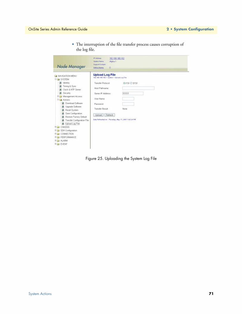
OnSite Series Admin Reference Guide 2 • System Configuration
• The interruption of the file transfer process causes corruption of the log file.
Figure 25. Uploading the System Log File
System Actions 71

Chapter 3 STM-1 Interface
Chapter contentsIntroduction ..........................................................................................................................................................74General Information..............................................................................................................................................74SDH Provisioning .................................................................................................................................................76
Enabling an STM-1 Port ................................................................................................................................76Disabling an STM-1 Port ...............................................................................................................................77Configuring the J0 Trace ................................................................................................................................78Configuring the Automatic Laser Shutdown (ALS) Function ..........................................................................78
Auto Mode ................................................................................................................................................79Manual Restart Mode ...............................................................................................................................79Manual Restart for Test Mode ..................................................................................................................79
Configuring the STM-1 in Linear 1+1 MSP Protection Mode ........................................................................80External Commands for 1+1 MSP Switching ............................................................................................81
Configuring the SDH Payload Structure .........................................................................................................83SDH and Client Port Connections........................................................................................................................86
2-way Connections .........................................................................................................................................861-way Connections .........................................................................................................................................87Drop-and-Continue Connections ...................................................................................................................88Multicast Connections ....................................................................................................................................90
SDH Alarms..........................................................................................................................................................92Monitoring SDH Alarms ................................................................................................................................92Changing SDH Alarm Default Severities ........................................................................................................94Displaying the Alarm Log ...............................................................................................................................95
SDH Performance Monitoring..............................................................................................................................96Monitoring STM-1 Port Performance ............................................................................................................97
Monitoring VC-n Performance .....................................................................................................................100Monitoring Pointer Justification Counts .......................................................................................................101Configuring SDH Threshold Crossing Alerts (TCA) ....................................................................................103Displaying the SDH TCA Event Log ............................................................................................................104
SDH Testing .......................................................................................................................................................105Configuring STM-1 Facility Loopback .........................................................................................................106Configuring Error Insertion ..........................................................................................................................107
Virtual Concatenation (VCAT)...........................................................................................................................108Introduction to VCAT ..................................................................................................................................108
VCAT Group Features for the OS1052 ..................................................................................................108VCAT Group Features for the OS1063 ..................................................................................................109Summary of VCAT Group Features for the OS-10-Series Systems ..........................................................109GFP Packet Transport Considerations ....................................................................................................109VCG Notation ........................................................................................................................................109Differential Delay ....................................................................................................................................110
72

OnSite Series Admin Reference Guide 3 • STM-1 Interface
Creating a VCG ............................................................................................................................................110Removing a VCG .........................................................................................................................................120Monitoring VCG Alarms ..............................................................................................................................121Displaying the Alarm Log .............................................................................................................................122VCAT Group Performance Monitoring ........................................................................................................122Link Capacity Adjustment Scheme (LCAS) ..................................................................................................124VCQ QoS .....................................................................................................................................................130
Subnetwork Connection Protection (SNCP).......................................................................................................132Provisioning STM-1 Ports in SNCP mode ...................................................................................................134Displaying and Configuring SNCP Path Settings .........................................................................................135Displaying and Configuring SNCP Path Status ............................................................................................136External Commands for SNCP Path Switching ............................................................................................137Creating Cross-Connections .........................................................................................................................139
Ring Operations ..................................................................................................................................................141Ring Synchronization ....................................................................................................................................141Adding and Deleting OS-10 Nodes ..............................................................................................................141
Adding OS-10 Nodes into a Ring ...........................................................................................................141Removing OS-10 Nodes from a Ring ......................................................................................................143
Linear ADM (2-Fiber).........................................................................................................................................144Interconnection of OS-10 Nodes in a 2-Fiber Linear ADM Topology ..........................................................144Synchronization of OS-10 Nodes in a 2-Fiber Linear ADM Topology .........................................................145
73

OnSite Series Admin Reference Guide 3 • STM-1 Interface
IntroductionThis chapter provides the procedures for provisioning, monitoring and testing of SDH STM-1 ports and VC-12, VC-3 and VC-4 termination points (TPs).
General InformationThe base OnSite OS-10 system provides two (2) optical STM-1 ports for connection to the SDH network. The ports operate at 155.520 Mbit/s and can be configured to operate as dual unprotected ports or as a pro-tected pair using Linear 1+1 MSP. The ports can also be configured in add-drop multiplexer (ADM) mode for operation in a ring network using SNCP path protection switching.
Note The factory default for the protection mode is unprotected.
The STM-1 supports the AU-4 payload structure and provides connectivity at the VC-4, VC-3, VC-12, and VC-11 levels, as shown in Figure 26.
Figure 26. STM-1 AU-4 Multiplexing Structure
The STM-1 interface complies with the following standards:
• ITU-T G.707
• ITU-T G.783
• ITU-T G.826/G.829 (performance monitoring)
• ITU-T G.823 and G.783 (jitter and wander)
• ITU-T G.957 (optical parameters)
Figure 27 on page 75 shows the location of the STM-1 ports on the base OS1052 and OS1063 systems. The transmit (Tx) and receive (Rx) sides for each port are clearly labeled in the front panel.
Introduction 74

OnSite Series Admin Reference Guide 3 • STM-1 Interface
Figure 27. STM-1 Ports on the Base OS1052 and OS1063 Systems
Table 25 provides the interconnection parameters for the STM-1 ports.
Table 26 summarizes the optical parameters for the S-1.1, L-1.1 and L-1.2 interfaces.
Note The S-1.1, L-1.1 and L-1.2 optical interfaces are factory-installed options.
Table 25. STM-1 Interconnection Parameters
Parameter Type Notes
Fiber Type SMF (single mode fiber) Standard G.652 fiberConnector SC DuplexOptical Reach S-1.1 15 km at 1310 nm (G.957)
L-1.1 15 km at 1310 nm (G.957)L-1.2 94 km at 1550 nm (G.957)
Table 26. Summary of S-1.1, L-1.1 and L-1.2 Optical Interface Parameters
Parameter Unit S-1.1 L-1.1 L-1.2
Wavelength Operating range nm 1261-1360 1263-1360 1480 to 1580Mean launched power Maximum dBm -8 0 0
Minimum dBm -15 -5 -5Attenuation Range dB 0 to 12 10 to 28 10 to 28Receiver Overload dBm -8 -10 -10
Sensitivity dBm -23 -34 -34
General Information 75

OnSite Series Admin Reference Guide 3 • STM-1 Interface
Note As a factory-installed option, the OS1063 platform is available with two STM-1 electrical interface (STM-1e) ports on the base system. The STM-1e ports comply with the G.703 specifications for electri-cal intefaces at 155.520 Mbit/s and use DIN 1.0/2.3 connectors for coaxial cables with 75-ohm impedance.
The maximum distances in Table 25 on page 75 for the S-1.1, L-1.1 and L-1.2 options are calculated based on the worst-case design approach in Annex A, G.957. Here, the maximum attenuation coefficient for installed G.652 fiber cable is specified as 0.8-dB/km for S-1.1, 0.5-dB/km for L-1.1, and 0.3-dB/km for L-1.2 applica-tions. This coefficient includes the losses due to installation splices, repair splices and the operating tempera-ture range. The actual maximum fiber interconnection distance is typically better than the worst-case design figure in G.957 and depends on the actual attenuation coeffiecient for the installed fiber plant (which is usually lower than the specified values in G.957). Also, the receiver sensitivity for the S-1.1, L-1.1 and L-1.2 interfaces on the OS-10 system is typically better than the values in G.957 by 3 dBm. Increased receiver sensitity results in a fiber span which is longer than the worst-case design value in G.957.
Note Use a power meter to ensure that the power level from the fiber that connects to the receive side of the STM-1 port is within the limits in Table 33 for the S-1.1, L-1.1 or L-1.2 interface whichever is used). You may need to use optical attenuators on the receive side of the port to prevent receiver overload when using short fiber cable lengths.
SDH ProvisioningThe following section provides the procedures for enabling and disabling STM-1 ports. It also provides the procedures for configuring the STM-1 payload structure and the interface protection options.
Enabling an STM-1 PortTo configure an STM-1 port for service, see Figure 28 on page 77 and follow these steps:
1. Select the CHASSIS folder from the navigation menu.
2. From the expanded CHASSIS folder, select Ports.
3. On the Ports page, select the STM-1 port being configured and click on Properties.
Note The system uses the following naming convention for STM-1 inter-faces: ST:slot/port. The OS-10 contains two STM-1 ports in slot 1 (the base system), that is, ST:1/1 and ST:1/2.
4. In the Port Properties window, set Admin Status to Enabled.
5. Click on Apply and then on Close to close the window.
On the Ports page, Admin Status for the selected STM-1 port should now read Enabled.
To protect your eyes, never look at the transmit LED or laser through a magnifying device while it is powered on. Never look directly at a fiber port on the chassis or at the ends of fiber cable when they are powered on.CAUTION
SDH Provisioning 76

OnSite Series Admin Reference Guide 3 • STM-1 Interface
Figure 28. Enabling an STM-1 Port
Note The operational status (Oper Status) for an STM-1 port is IS (in ser-vice) when the port Admin Status is Enabled and no alarms are present at the RS and MS layers. Otherwise, the Oper Status for the port indicates OOS (out of service).
Disabling an STM-1 PortTo disable an STM-1 port from service, see Figure 28 and follow these steps:
1. In the Port Properties window, set Admin Status to Disabled.
2. Click on Apply and then on Close to close the window.
On the Ports page, Admin Status for the selected STM-1 port should now read Disabled.
Note When an STM-1 port is disabled, no port-related alarms are reported. PM data collection is also suspended. Furthermore, the dis-abled port transmits MS-AIS over the physical line interface.
SDH Provisioning 77

OnSite Series Admin Reference Guide 3 • STM-1 Interface
Configuring the J0 TraceTo configure the J0 trace message for the STM-1 port, see Figure 28 on page 77 and follow these steps:
1. In the Port Properties window, set the J0 Trace to Enabled.
2. Type the Expected Trace and the Transmitted Trace using up to 15 ASCII characters for each field.
Note The system inserts the transmitted trace into the outgoing J0 byte for the port.
3. Click on Apply and then on Close to close the window.
Note The system does not allow enabling the J0 trace with the expected trace and transmitted trace fields empty. The system automatically enables the detection of the RS-TIM defect when J0 Trace is set to Enabled and the Expected Trace contains one or more ASCII charac-ters. The system displays the Received Trace message if any is being received from the incoming J0 byte for the port.
Configuring the Automatic Laser Shutdown (ALS) FunctionThe system supports the automatic laser shutdown (ALS) function in accordance with G.958. The ALS func-tion works in three modes: Auto, Manual Restart and Manual Restart for Test. By default, the ALS function is disabled.
When the ALS function is disabled, the system lets you manually turn the STM-1 laser on or off.
To configure the laser for manual on/off operation, see Figure 28 on page 77 and follow these steps:
1. In the Port Properties window, set the Laser Config to On or Off.
2. Click on Apply and then on Close to close the window.
Note The Laser Status indicates the current operation status of the laser: On or Off. The laser may be in the “on” or “off ” state as a result of manual configuration or because of the application of the ALS func-tion.
SDH Provisioning 78

OnSite Series Admin Reference Guide 3 • STM-1 Interface
Auto ModeIn Auto mode, the transmit laser of the STM-1 port automatically shuts down when the receiver side of the port detects a loss-of-signal (LOS) condition for more than 0.5 seconds. After this event, the system periodi-cally waits for 100-300 seconds and sends an optical pulse of 2-10 seconds of width to try recovering normal operation over the fiber link. If the link is restored and the STM-1 port on the other side of the link is also con-figured in ALS Auto mode, the successful reception of the optical pulse restarts the associated laser for contin-uous operation. This event, in turn, restarts the laser on the other side of the link and results in the recovery of normal operation over both sides of link.
To enable and configure the ALS function for the STM-1 port in Auto mode, see Figure 28 on page 77 and follow these steps:
1. In the Port Properties window, set the ALS Mode to Auto.
By default, the ALS Pulse Recovery Interval is set to 100 seconds. You can change this parameter to any valid value in the range of 100-300 seconds.
By default, the ALS Pulse Recovery Width is 2 seconds. You can change this parameter to any valid value in the range of 2-10 seconds.
2. Click on Apply and then on Close to close the window.
Manual Restart ModeIn Manual Restart mode, the system allows you to restart the laser manually at any time without having to wait for the completion of the pulse recovery interval. The system can enter the Manual Restart mode only when the STM-1 port was previously configured in Auto mode and the laser is shut down by the ALS function.
To configure the ALS function in Manual Restart mode, see Figure 35 and follow these steps.
1. In the Port Properties window, set the ALS Mode to Manual.
2. Click on the Activate ALS Manual Command.
At this time, the STM-1 port sends a single optical pulse with a width set by the ALS Pulse Recovery Width. In Manual Restart mode, the ALS Pulse Recovery Interval has no meaning, because the system sends only one optical pulse when the command is applied.
3. Click on Apply and then on Close to close the window.
Manual Restart for Test ModeIn Manual Restart for Test mode, the system works in the same way as the Manual Restart mode, except that the width of the opical pulse is fixed to 90 seconds. In this mode, both the ALS Pulse Recovery Width and the ALS Pulse Recovery Interval parameters have no meaning, because the system sends only one pulse of fixed duration when the command is applied.
SDH Provisioning 79

OnSite Series Admin Reference Guide 3 • STM-1 Interface
Configuring the STM-1 in Linear 1+1 MSP Protection ModeThe STM-1 interfaces can be provisioned either as protected or unprotected.
Note The factory default for the STM-1 protection mode is unprotected.
The system supports two protection modes when using Linear 1+1 MSP:
• unidirectional, non-revertive (default)
• unidirectional, revertive
Note When the STM-1 interface is provisioned for Linear 1+1 MSP, the factory default is unidirectional, non-revertive.
To configure an STM-1 port for protection, see Figure 29 on page 81 and follow these steps:
1. Select the SDH Configuration folder from the navigation menu.
2. From the expanded SDH Configuration folder, select the Protection folder.
3. From the expanded Protection folder, select the Linear 1+1 MSP folder.
4. From the expanded Linear 1+1 MSP folder, select Settings.
5. On the Linear 1+1 MSP page, select Create 1+1 MSP.
6. In the Linear 1+1 MSP Provisioning window, select the STM-1 Working Port and Protection Port pair from the available list of ports using the scroll-down button, click on Apply and then on Close to close the window.
This action completes the provisioning process using the default MSP parameters.
On the Linear 1+1 MSP page, the table now contains an entry with a summary of the provisioned parameters.
To configure the system for revertive switching, see Figure 29 on page 81 and follow these steps:
Note After the failed direction on the working port returns to normal, revertive switching causes the system to wait for a preset amount of time (that is, the Wait-to-Restore time) before the selector on the receive side switches back from the protection port to the working port.
1. On the Linear 1+1 MSP page, click on Properties.
2. In the Linear 1+1 MSP Properties window, select Revertive.
To change the Wait-to-Restore time, continue with Step 3; otherwise, go directly to Step 5 to complete this task.
Note The Wait-to-Restore time applies only when using revertive switch-ing. Its value is ignored when using non-revertive switching.
3. In the Linear 1+1 MSP Properties window, change the Wait-To-Restore Time from the factory default setting of 5 (minutes) to any integer between 0 and 12 minutes.
SDH Provisioning 80

OnSite Series Admin Reference Guide 3 • STM-1 Interface
To change the BER settings for the detection of Signal Degrade (DEG) and Excessive Errors (EXC) at the STM-1 MS layer, continue with Step 4; otherwise, go directly to Step 5 to complete this task.
4. In the Linear 1+1 MSP Properties window, select the desired BER setting using the DEG (or EXC) Threshold scroll-down button.
5. Click on Apply and then on Close to close the window.
At this point, the table entry on the Linear 1+1 MSP page reflects any recent configuration changes.
Figure 29. Enabling and Configuring 1+1 MSP Protection
External Commands for 1+1 MSP SwitchingThe system allows the use of external commands to switch between working and protection ports.
Table 27 provides a list of the external commands that the system supports:
Table 27. External Commands for 1+1 MSP Switching
Priority Command Action Completion
1 Clear Clears all switch commands Always2 Lockout Disables a switch to the protection
portAlways
3 Forced to Protection Switches from the working to the protection port
Denied if the SF condition is present on the protection port or if the Lockout com-mand is present
Forced to Working Switches from the protection to the working port
Denied if the Lockout command is present
SDH Provisioning 81

OnSite Series Admin Reference Guide 3 • STM-1 Interface
To activate any of the external commands for 1+1 MSP switching, see Figure 37 and follow these steps:
1. Select the SDH Configuration folder from the navigation menu.
2. From the expanded SDH Configuration folder, select the Protection folder.
3. From the expanded Protection folder, select the Linear 1+1 MSP folder.
4. From the expanded Linear 1+1 MSP folder, select Status & Command.
5. On the Linear 1+1 MSP Status page, select the table entry and click on Status/Command.
6. In the MSP Status & Switch Command window, use the scroll-down button to select one of the Com-mand options in Table 27.
Note By default, Command is set to No Command. The MSP Status & Switch Command window also displays the current status of the pro-tection group, including the transmitted and received values for the K1 and K2 bytes and the status of the protection switch selector.
7. Click on Initiate Command to activate the external command.
8. To reset any active command, select the Clear command option and click on Initiate Command. Other-wise, the current command remains active until a higher priority command is issued or failure event occurs (see Table 27 on page 81).
Figure 30. Configuring the External 1+1 MSP Protection Switch Commands
4 Manual to Protection Switches from the working to the protection port
Denied if the SF or SD condition is present on the protection port or if the Lockout or Forced command is present
Manual to Working Switches from the protection to the working port
Denied if the SF or SD condition is present on the working port or if the Lockout or Forced command is present
Table 27. External Commands for 1+1 MSP Switching
Priority Command Action Completion
SDH Provisioning 82

OnSite Series Admin Reference Guide 3 • STM-1 Interface
Configuring the SDH Payload StructureThe OnSite OS-10 system allows you to configure the STM-1 to carry any standards-based combination of VC-4, VC-3 and VC-12 payloads. The system uses a simple, standards-based index to help you identify the location of SDH structures within the STM-1 port. All SDH structures are uniquely identified by four letters, as indicated in Table 28.
Table 29 summarizes the structures and ranges represented by the index.
As shown in Table 29, the same index is shared by a number of SDH structures.
Note Because only one AU-4 exists within the STM-1, the value of U is always 1. TU-2 and VC-2 structures are not supported in the system but are included in Table 36 for illustration purposes and complete-ness. Most, if not all, SDH equipment to which the OS-10 connects does not support switching and connectivity at this level.
Table 28. Index Letters to Identify SDH Structures
Letter Indicates the Location of
U AU-4 (VC-4) within the STM-1K TUG-3 within a VC-4L TUG-2 within a TUG-3M TU-12 within a TUG-2
Table 29. Provisioning Range for SDH Structures
Index Letter SDH Structures Provisioning Range
U AUG-1 AU-4 VC-4 1K TUG-3 TU-3 VC-3 1 to 3L TUG-2 TU-2* VC-2* 1 to 7M – TU-12 VC-12 1 to 3
SDH Provisioning 83
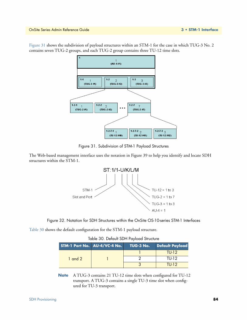
OnSite Series Admin Reference Guide 3 • STM-1 Interface
Figure 31 shows the subdivision of payload structures within an STM-1 for the case in which TUG-3 No. 2 contains seven TUG-2 groups, and each TUG-2 group contains three TU-12 time slots.
Figure 31. Subdivision of STM-1 Payload Structures
The Web-based management interface uses the notation in Figure 39 to help you identify and locate SDH structures within the STM-1.
Figure 32. Notation for SDH Structures within the OnSite OS-10-series STM-1 Interfaces
Table 30 shows the default configuration for the STM-1 payload structure.
Note A TUG-3 contains 21 TU-12 time slots when configured for TU-12 transport. A TUG-3 contains a single TU-3 time slot when config-ured for TU-3 transport.
Table 30. Default SDH Payload Structure
STM-1 Port No. AU-4/VC-4 No. TUG-3 No. Default Payload
1 and 2 11 TU-122 TU-123 TU-12
SDH Provisioning 84
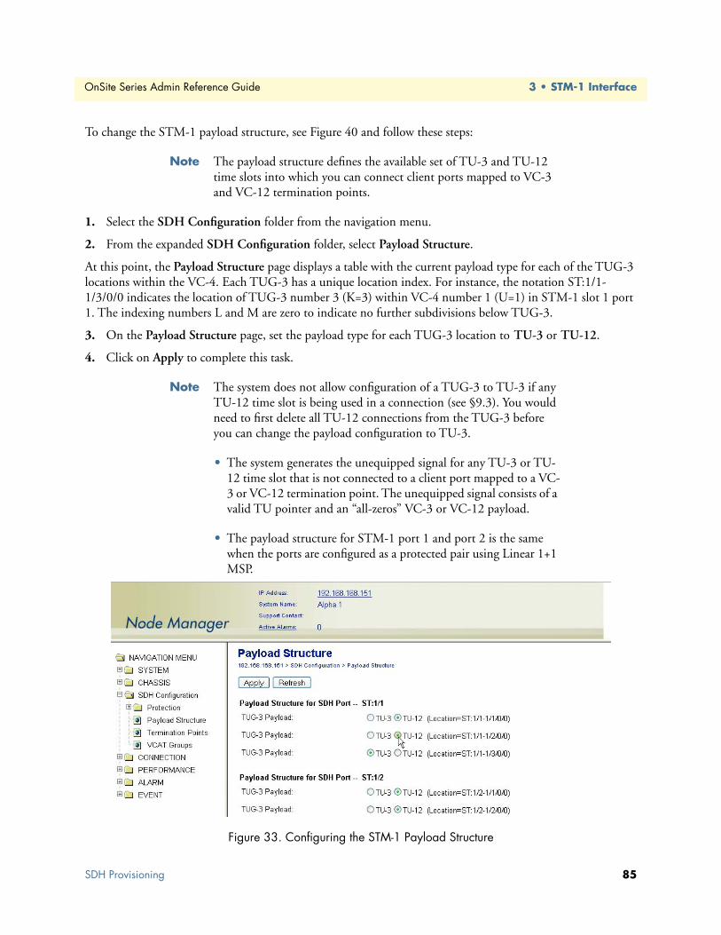
OnSite Series Admin Reference Guide 3 • STM-1 Interface
To change the STM-1 payload structure, see Figure 40 and follow these steps:
Note The payload structure defines the available set of TU-3 and TU-12 time slots into which you can connect client ports mapped to VC-3 and VC-12 termination points.
1. Select the SDH Configuration folder from the navigation menu.
2. From the expanded SDH Configuration folder, select Payload Structure.
At this point, the Payload Structure page displays a table with the current payload type for each of the TUG-3 locations within the VC-4. Each TUG-3 has a unique location index. For instance, the notation ST:1/1-1/3/0/0 indicates the location of TUG-3 number 3 (K=3) within VC-4 number 1 (U=1) in STM-1 slot 1 port 1. The indexing numbers L and M are zero to indicate no further subdivisions below TUG-3.
3. On the Payload Structure page, set the payload type for each TUG-3 location to TU-3 or TU-12.
4. Click on Apply to complete this task.
Note The system does not allow configuration of a TUG-3 to TU-3 if any TU-12 time slot is being used in a connection (see §9.3). You would need to first delete all TU-12 connections from the TUG-3 before you can change the payload configuration to TU-3.
• The system generates the unequipped signal for any TU-3 or TU-12 time slot that is not connected to a client port mapped to a VC-3 or VC-12 termination point. The unequipped signal consists of a valid TU pointer and an “all-zeros” VC-3 or VC-12 payload.
• The payload structure for STM-1 port 1 and port 2 is the same when the ports are configured as a protected pair using Linear 1+1 MSP.
Figure 33. Configuring the STM-1 Payload Structure
SDH Provisioning 85

OnSite Series Admin Reference Guide 3 • STM-1 Interface
SDH and Client Port ConnectionsThe system supports the following types of connections:
• 2-way (bidirectional)
• 1-way (unidirectional)
• 1-way drop-and-continue
• 2-way drop-and-continue
• 1-way multicast
The following sections provide an overview of each type of connection.
2-way ConnectionsBy default, the system uses 2-way connections to connect traffic between STM-1 ports and client signal ports (E1/T1, E3/DS3 and Ethernet). Figure 34 shows examples of 2-way add-drop connections between E1 client signal ports and unprotected TU-12 timeslots. As shown in the figure, the E1 port can be connected to an unprotected TU-12 on either STM-1 port 1 (west) or port 2 (east). The figure also shows an example of a 2-way cross-connection between TU-12 timeslots on STM-1 port 1 (west) and 2 (east).
Note that each connection point has two components: a source (So) and a sink (So). The So side is where the connection originates and the Sk side is where the connection terminates. To set up a 2-way connection, is only necessary to identify one of the connection points as the So and the other as the Sk.
Which of the two connection points is identified as the So or the Sk is not important. The 2-way relationship between the two connection points binds the So and Sk sides for each connection point together.
Figure 34. Unprotected 2-way Connections (Examples)
SDH and Client Port Connections 86
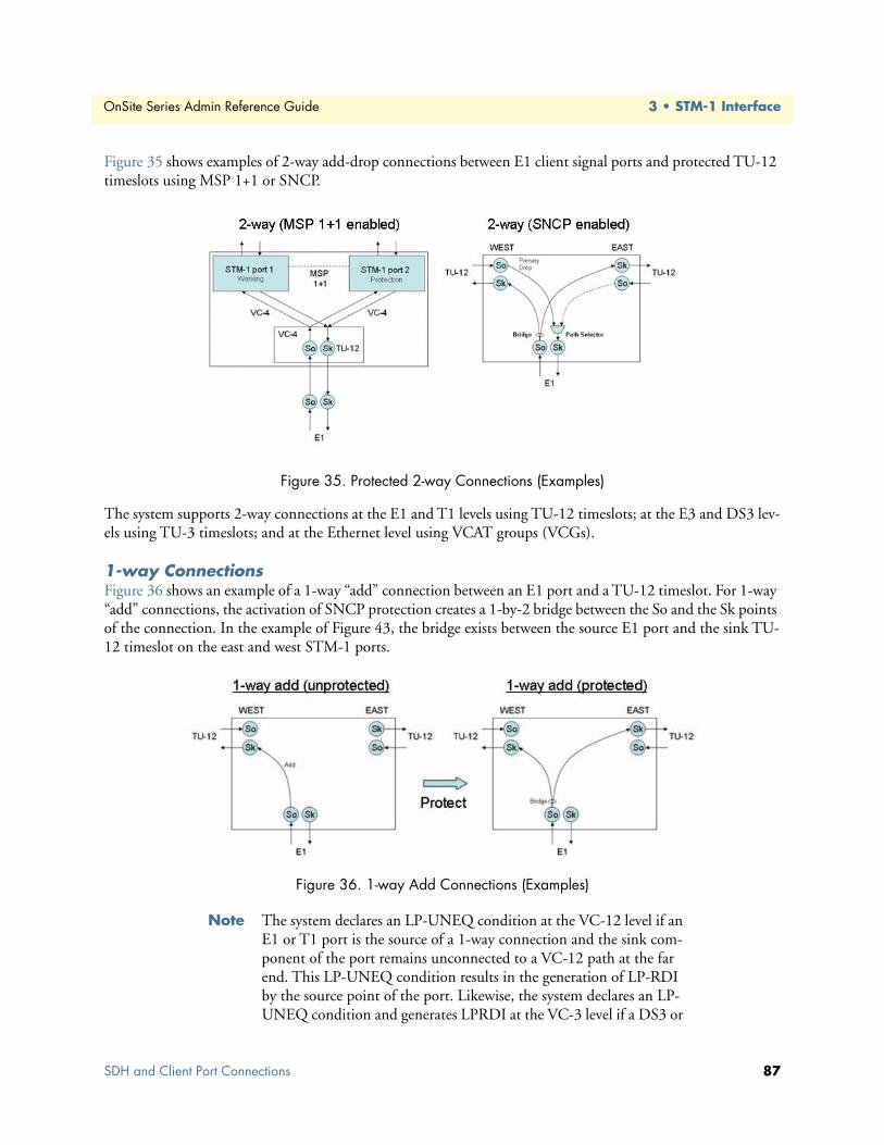
OnSite Series Admin Reference Guide 3 • STM-1 Interface
Figure 35 shows examples of 2-way add-drop connections between E1 client signal ports and protected TU-12 timeslots using MSP 1+1 or SNCP.
Figure 35. Protected 2-way Connections (Examples)
The system supports 2-way connections at the E1 and T1 levels using TU-12 timeslots; at the E3 and DS3 lev-els using TU-3 timeslots; and at the Ethernet level using VCAT groups (VCGs).
1-way ConnectionsFigure 36 shows an example of a 1-way “add” connection between an E1 port and a TU-12 timeslot. For 1-way “add” connections, the activation of SNCP protection creates a 1-by-2 bridge between the So and the Sk points of the connection. In the example of Figure 43, the bridge exists between the source E1 port and the sink TU-12 timeslot on the east and west STM-1 ports.
Figure 36. 1-way Add Connections (Examples)
Note The system declares an LP-UNEQ condition at the VC-12 level if an E1 or T1 port is the source of a 1-way connection and the sink com-ponent of the port remains unconnected to a VC-12 path at the far end. This LP-UNEQ condition results in the generation of LP-RDI by the source point of the port. Likewise, the system declares an LP-UNEQ condition and generates LPRDI at the VC-3 level if a DS3 or
SDH and Client Port Connections 87

OnSite Series Admin Reference Guide 3 • STM-1 Interface
E3 port is the source of a 1-way connection and the sink component of the port remains unconnected to a VC-3 path at the far end. Also, for an Ethernet flow that originates a 1-way connection to a VCG, LP-UNEQ detection and LP-RDI generation occurs for all VCG members that remain unconnected at the sink point to VC-3 or VC-12 paths at the far end.
Figure 37 shows an example of a 1-way “drop” connection between an E1 port and a TU-12 timeslot. For 1-way “drop” connections, the activation of SNCP protection creates a path selector between the So and Sk points of the connection. In the example of Figure 44, the path selector exists between the source TU-12 timeslot on the east and west STM-1 ports and the E1 port at the sink.
Figure 37. 1-way Drop Connections (Examples)
The system supports 1-way connections at the E1 and T1 levels using TU-12 timeslots; at the E3 and DS3 lev-els using TU-3 timeslots; and at the Ethernet level using VCAT groups (VCGs).
Drop-and-Continue ConnectionsThe system supports two types of drop-and-continue connections: 1-way and 2-way drop-and-continue. Figure 38 on page 89 shows an example of a 1-way drop-and-continue connection at the E1 level. In a 1-way E1 drop-and-continue connection from west, the system drops a TU-12 timeslot from the west port (STM-1 port 1) into an E1 port while a copy of the VC-12 payload on the TU-12 continues onwards to the same TU-12 location on the east port (STM-1 port 2). When SNCP is enabled for a 1-way drop-and-continue connec-tion from west, the system makes a similar connection from the east port and turns on a path selector function that uses the drop side from the west as the primary drop path and the drop side from the east as the secondary drop path. Likewise, Figure 38 shows an example of a 1-way E1 drop-and-continue connection from east.
SDH and Client Port Connections 88

OnSite Series Admin Reference Guide 3 • STM-1 Interface
Figure 38. 1-way Drop-and-Continue Connections (Examples)
Figure 39 on page 90 shows an example of a 2-way drop-and-continue connection at the E1 level. In contrast to 1-way E1 drop-and-continue connections, 2-way E1 drop-and-continue connections support 2-way trans-mission between a TU-12 timeslot and an E1 port while a copy of the VC-12 payload on the TU-12 continues onwards to the same TU-12 location on the other STM-1 port. As Figure 46 shows, when SNCP is enabled for a 2-way drop-and-continue connection from west, the system turns on a path selector function that uses the drop side from west as the primary drop path and the drop side from the east as the secondary drop path. There is no “continue” component from the east port (as in 1-way drop-andcontinue connections) because the “add” part of the connection from the E1 port occupies the corresponding TU-12 on the west port. Likewise, Figure 39 shows an example of a 2-way E1 drop-andcontinue connection from the east port.
SDH and Client Port Connections 89

OnSite Series Admin Reference Guide 3 • STM-1 Interface
Figure 39. 2-way Drop-and-Continue Connections (Examples)
The system supports drop-and-continue connections at the E1 and T1 levels using TU-12 timeslots; at the E3 and DS3 levels using TU-3 timeslots; and at the Ethernet level using VCAT groups (VCGs).
Multicast ConnectionsThe system supports multicast connections at the E1 and T1 levels using TU-12 timeslots; at the E3 and DS3 levels using TU-3 timeslots; and at the Ethernet level using VCAT groups (VCGs). The system also supports multicast connections at the VC-12 level between TU-12 timeslots, and at the VC-3 level between TU-3 timeslots.
As shows, for an E1 multicast connection from west, the system drops a TU-12 timeslot on the west port into a single E1 port. At this point, the multicast connection with a single leg (Leg 1) looks the same as an unpro-tected 1-way drop connection (see Figure 44). However, because the initial leg is part of a multicast connec-tion, you can create additional multicast legs (Legs 2 and 3 in Figure 47) to connect the same TU-12 timeslot to other E1 ports in the system. The system does place restrictions on the maximum number of multicast legs originating from one TU-12, as long as there are E1 or TU-12 sink points available.
When SNCP is enabled for a 1-way multicast connection from west, the system turns on a path selector func-tion that uses the drop side from west as the primary drop path and the drop side from the east as the second-ary drop path. Note that the system applies the SNCP path selector to only one TU-12 timeslot, and that the selected path (east or west) becomes the source for all multicast legs.
SDH and Client Port Connections 90

OnSite Series Admin Reference Guide 3 • STM-1 Interface
Note To provide the equivalent function of a combined 1-way multicast and drop-and-continue connection, you can create an additional leg between the TU timeslots on the east and west ports.
Figure 40 also provides an example of a multicast connection at the Ethernet level. In contrast to multicast connections at the E1/T1 or E3/DS3 level, multicast connections at the Ethernet level occur at the packet level within the high-density Ethernet (HD-ENET) expansion module.
Once the system makes the first multicast connection from a VCG into an Ethernet port on the HD-ENET module (Leg 1), you can create additional multicast legs (see Legs 2 and 3 in Figure 40) to connect the same Ethernet flow from the VCG to other Ethernet ports in the module. The system does place restrictions on the maximum number of multicast legs originating from one VCG, as long as there are Ethernet flow sink points available in the module.
When SNCP is enabled for a 1-way multicast connection from a VCG, the system turns on a path selector function for each member of the VCG. The selected path (east or west) for each member becomes part of the VCG that originates all multicast legs at the Ethernet level.
Figure 40. 1-way Multicast Connections (Examples)
SDH and Client Port Connections 91

OnSite Series Admin Reference Guide 3 • STM-1 Interface
SDH AlarmsThe system monitors SDH alarms according to Recommendations G.707, G.783 and G.826. The following sections provide the procedures for monitoring active SDH alarms, changing the alarm severity, and displaying the alarm log.
Note The system declares and displays an alarm condition if a defect per-sists for 2.5 ± 0.5 seconds. The alarm condition is cleared when the defect is terminated and remains absent for 10 ± 0.5 seconds.
Monitoring SDH AlarmsTable 31 provides a list of the SDH alarms that the system supports.
Note The system declares an MS-EXC (excessive errors) condition when the measured BER (bit error rate) exceeds a provisioned value. The BER is calculated based on the results of the B2 byte at the MS layer. The supported BER thresholds for declaring MS-EXC are: 10-5, 10-4, and 10-3. (10-3 is the default.) The system initiates a protection switch upon detecting MS-EXC. This applies only to systems config-ured for 1+1 operation.
Note The system declares an MS-DEG (degraded signal) condition when the measured BER exceeds 10-6 (default setting). The supported BER thresholds for declaring MS-DEG are: 10-9, 10-8, 10-7, 10-6,
Table 31. SDH Alarms
Monitored Entity Near-end Alarm Description Far-end Alarm Description
STM-1 RSLOS Loss of SignalLOF Loss of FrameRS-TIM Trace identifier mismatch
STM-1 MSMS-AIS Alarm Indication Signal
MS-RDI Remote Defect IndicationMS-EXC Excessive ErrorsMS-DEG Degraded Signal
AU-4 AU-AIS Alarm Indication SignalAU-LOP Loss of Pointer
VC-4HP-UNEQ Unequipped
HP-RDI Remote Defect IndicationHP-PLM Path Label MismatchHP-TIM Trace identifier mismatch
TU-3 and
TU-12
TU-AIS Alarm Indication SignalTU-LOP Loss of PointerTU-LOM Loss of Multiframe
VC-3 and
VC-12
LP-UNEQ UnequippedLP-RDI Remote Defect IndicationLP-PLM Path Label Mismatch
LP-TIM Trace identifier mismatch
SDH Alarms 92

OnSite Series Admin Reference Guide 3 • STM-1 Interface
and 10-5. (10-6 is the default.) The system initiates a protection switch upon detecting MS-DEG. This applies only to systems config-ured for 1+1 operation.
The front panel provides an alarm status LED for each STM-1 port (port 1 and port 2) to indicate the pres-ence of an active alarm condition of any severity level (Critical, Major, Minor, or Warning). The LED is lit according to the color codes in Table 32.
To display SDH alarms, if present, see Figure 48 and follow these steps:
1. Select the ALARM folder from the navigation menu.
2. From the expanded ALARM folder, select Show Active Alarms.
At this point, the Active Alarms page displays all active alarms in the system, including SDH alarms, if present. The table contains a separate entry for each active SDH alarm. Table 33 describes the fields for each SDH alarm entry.
Note The system automatically updates the Active Alarms page every 60 seconds. Click on Refresh if you need to update the table with the most recent active alarm information. Individual table entries auto-matically clear whenever previously active alarms are no longer present.
Figure 41. Displaying SDH Alarms
Table 32. STM-1 Alarm Status LED
LED Color Description
Green No alarm is present on the STM-1 port.Amber An alarm is present on the STM-1 port.
Off The STM-1 port is disabled.
Table 33. Table Entries for Active SDH Alarms
Table Entry for Active Alarms Field Value
Type See Table 31 on page 92 for a complete list of SDH alarms.Alarm Raised Time Date and time
Severity Critical, Major, Minor, or WarningDetailed Information Location of affected SDH entity (ST:slot/port or ST:slot/port-U/K/L/M)
SDH Alarms 93

OnSite Series Admin Reference Guide 3 • STM-1 Interface
Changing SDH Alarm Default SeveritiesThe system allows changing the default severity of any given SDH alarm condition. Alarm severities are the following:
• Critical
• Major
• Minor
• Warning
Table 34 provides the default severities for SDH alarms:
To change the default severity for supported SDH alarms, see Figure 42 on page 95 and follow these steps:
1. Select the ALARM folder from the navigation menu.
2. From the expanded ALARM folder, select Set Alarm Severity.
At this point, the Alarm Severity page displays a table with all supported system alarms.
3. Select the table entry containing the SDH alarm Type and click on Change.
4. In the Alarm Severity window, set Severity to any desired level (Critical, Major, Minor, or Warning).
5. Click on Apply and then on Close to close the window.
On the Alarm Severity page, the Severity for the selected SDH alarm Type should now reflect the change in the reported severity level.
Table 34. SDH Alarm Default Severities
Monitored Entity Near-end Alarm Default Severity Far-end Alarm Default Severity
STM-1 RSLOS CriticalLOF CriticalRS-TIM Major
STM-1 MSMS-AIS Major
MS-RDI MajorMS-EXC MajorAU-4 AU-AIS Major
AU-LOP Major
VC-4HP-UNEQ Critical
HP-RDI MajorHP-PLM CriticalHP-TIM Major
TU-3 and
TU-12
TU-AIS MajorTU-LOP CriticalTU-LOM Critical
VC-3 and
VC-12
LP-UNEQ CriticalLP-RDI MajorLP-PLM Critical
LP-TIM Critical
SDH Alarms 94
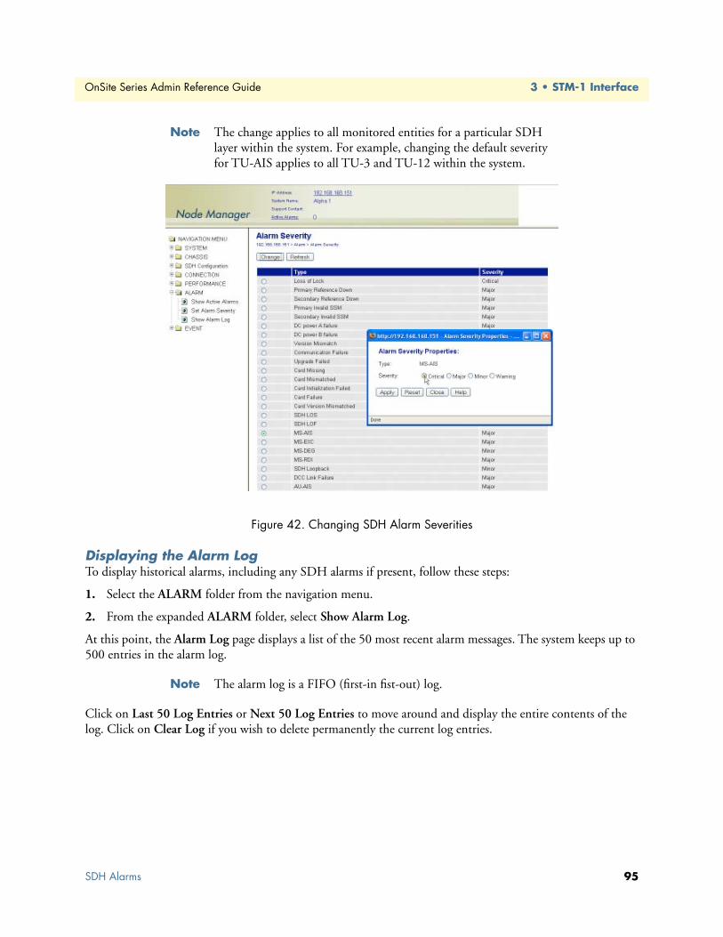
OnSite Series Admin Reference Guide 3 • STM-1 Interface
Note The change applies to all monitored entities for a particular SDH layer within the system. For example, changing the default severity for TU-AIS applies to all TU-3 and TU-12 within the system.
Figure 42. Changing SDH Alarm Severities
Displaying the Alarm LogTo display historical alarms, including any SDH alarms if present, follow these steps:
1. Select the ALARM folder from the navigation menu.
2. From the expanded ALARM folder, select Show Alarm Log.
At this point, the Alarm Log page displays a list of the 50 most recent alarm messages. The system keeps up to 500 entries in the alarm log.
Note The alarm log is a FIFO (first-in fist-out) log.
Click on Last 50 Log Entries or Next 50 Log Entries to move around and display the entire contents of the log. Click on Clear Log if you wish to delete permanently the current log entries.
SDH Alarms 95

OnSite Series Admin Reference Guide 3 • STM-1 Interface
SDH Performance MonitoringThe following sections provide the procedures for displaying current and historical SDH performance moni-toring (PM) data and configuring and displaying PM thresholds.
The system calculates the SDH error performance events listed inTable 35 in accordance to Recommendations G.826 and G.829.
Note A period of unavailable time begins at the onset of 10 consecutive SES seconds. These 10 seconds are part of unavailable time. A period of available time begins at the onset of 10 consecutive non-SES sec-onds. These 10 seconds are part of available time.
Table 36 provides a list of the near-end PM parameters that the system collects at various SDH layers.
For each PM parameter, near-end PM data is stored in the following counters:
• Current 15 minutes
• Recent 15 minutes (previous 95-by-15 minute intervals)
• Current 24 hours
• Recent 24 hours (previous day only)
Note PM event counting for BBE, ES, and SES is inhibited during unavail-able time in accordance to Recommendations G.826 and G.829.
Table 35. SDH Error Performance Events
PM Parameter Description Definition
BBE Background Block Error An EB (errored block) not part of an SESES Errored Second A second containing at least one EB or a defectSES Severely Errored Second A second containing K1 or more EBs or a defectUAS Unavailable Second A period of unavailable time that begins at the
onset of 10 consecutive SES
Table 36. Monitored PM Parameters at Various SDH Layers
SDH Layer Monitored Entity PM Parameters
RS STM-1 BBE, ES, and SESMS STM-1 BBE, ES, SES, and UASHP VC-4 BBE, ES, SES, and UASLP VC-3 and VC-12 BBE, ES, SES, and UAS
SDH Performance Monitoring 96

OnSite Series Admin Reference Guide 3 • STM-1 Interface
By default, the system uses the SES threshold values in Table 37.
The SES threshold value (for example, 2,400 for VC-3) is the value “K” in the definition of SES in Table 35 on page 96.
Note According to G.829, PM counting at the STM-1 MS layer is based on 24 BIP-1 counts using the B2 bytes. This counting method is dif-ferent from the other layers and results in up to 24 EBs per frame, and a maximum of 192,000 EBs per second.
Monitoring STM-1 Port PerformanceTo display current PM data for an STM-1 port, see Figure 43 and follow these steps:
1. Select the CHASSIS folder from the navigation menu.
2. From the expanded CHASSIS folder, select Ports.
3. On the Ports page, select the STM-1 port being configured and click Show PM.
At this point, the STM-1 Regenerator Section Near-end PM page shows the near-end PM data for both the current 15-minute and 24-hour periods. The PM data is not updated automatically as new events occur during the Current 15-minute and 24-hour periods. Click on Refresh to update the tables with the most recent cumulative count for the current periods.
Figure 43. Displaying Current PM Data for an STM-1 Port
Table 37. SDH SES Threshold Values
Monitored Entity SES Threshold Applicable Standard
VC-12 600 EB G.826VC-3 2,400 EB G.826VC-4 2,400 EB G.826
STM-1 RS 2,400 EB G.829STM-1 MS 28,800 EB G.829
SDH Performance Monitoring 97

OnSite Series Admin Reference Guide 3 • STM-1 Interface
Continue with the steps below to display historical PM data.
4. Click on Show Interval.
At this point, the STM-1 Regenerator Section Near-end PM page shows the near-end PM data for the follow-ing intervals (see Figure 44):
• Current plus previous 95-by-15-minute intervals (24 hours total)
• Current plus previous day (2 days total)
Click on Refresh to update the tables with the most recent cumulative count for the current periods. This action updates only the first entry in the tables, which corresponds to the current measurement period.
Note The tables display Invalid under PM data when the data collected during a measurement period is considered invalid. The Interval Start Time also displays n/a (not available).
Figure 44. Displaying PM Data Intervals for an STM-1 Port
SDH Performance Monitoring 98

OnSite Series Admin Reference Guide 3 • STM-1 Interface
To display current and historical PM data for all STM-1 ports in the system, follow these steps:
1. Select the PERFORMANCE folder from the navigation menu.
2. From the expanded PERFORMANCE folder, select Counters.
3. From the expanded Counters folder, select SDH.
4. From the expanded SDH folder, select STM-1 RS.
At this point, the STM-1 Regenerator Section Near-end PM page shows the near-end PM data for the current 15-minute period only (see Figure 45).
Note You may select STM-1 MS instead of STM-1 RS in Step 4 to display the corresponding near-end PM data for the STM-1 MS layer.
Continue with the steps that follow to display historical PM data for both 15-minute and 24-hour periods.
5. Select an STM-1 port and click on Show Interval.
Note The preceding notes for the STM-1 Regenerator Section Near-end PM page also apply to this procedure.
Figure 45. Displaying Current PM Data for All STM-1 Ports
To clear the current PM data for an STM-1 port, see Figure 45and follow this step:
1. On the STM-1 Regenerator Section Near-end PM page, select one of the STM-1 port entries and use the Clear Counter Options... scroll-down button to select one of the available options for clearing the current 15 minute or 24 hour counters, or both.
SDH Performance Monitoring 99

OnSite Series Admin Reference Guide 3 • STM-1 Interface
Monitoring VC-n PerformanceTo display current and historical PM data for all VC-12, VC-3, or VC-4 termination points (TPs) in the sys-tem, see Figure 46 and follow these steps:
Note The system displays PM data only for VC-12 or VC-3 TPs that are connected to a client port.
1. Select the PERFORMANCE folder from the navigation menu.
2. From the expanded PERFORMANCE folder, select Counters.
3. From the expanded Counters folder, select SDH.
4. From the expanded SDH folder, select VC-12, VC-3 or VC-4.
At this point, the VC-12, VC-3 or VC-4 Near-end PM page shows the near-end PM data for the current 15-minute period only. Figure 53 shows an example for the VC-12 Near-end PM page.
Continue with the steps that follow to display historical PM data for both 15-minute and 24-hour periods.
5. Step 5 Select the TP Location for a VC-12 (or a VC-3 or VC-4) TP and click on Show Interval.
Figure 46. Displaying Current VC-12 PM Data
To clear the current PM data for a VC-12 TP, see Figure 46 and follow these steps:
1. On the VC-12 Near-end PM page, select one of the STM-1 port entries and use the Clear Counter Options... scroll-down button to select one of the available options for clearing the current 15 minute or 24 hour counters, or both.
SDH Performance Monitoring 100

OnSite Series Admin Reference Guide 3 • STM-1 Interface
Monitoring Pointer Justification CountsThe system supports the collection of PM data for pointer justification counts (PJC). Separate counters are provided for detection and generation of both positive and negative pointer adjustments, as shown in Table 38.
The system provides only one set of PJC counters for a given AU or TU level:
• One set for AU-4 pointers
• One set for TU-3 or TU-12 pointers
You can indicate the AU-4, TU-3 or TU-12 entity that you wish to monitor.
To display current and historical PM data for selected PJC counters, see Figure 47 on page 102and follow these steps:
1. Select the PERFORMANCE folder from the navigation menu.
2. From the expanded PERFORMANCE folder, select Counters.
3. From the expanded Counters folder, select SDH.
4. From the expanded SDH folder, select PJC.
5. From the expanded PJC folder, select Monitoring Points.
6. On the Pointer Justification Count -- Monitoring Points page, select one of the Pointer Level options (AU-4, TU-3 or TU-12).
At this point, the table on the Pointer Justification Count -- Monitoring Points page displays the pointer loca-tions that are currently being monitored, if any were previously selected.
Note By default, no AU or TU pointer locations are monitored.
7. In the Pointer Justification Count -- Monitoring Points window, select one of the available Pointer Loca-tions using the scroll-down button.
8. Click on Apply and then on Close to close the window.
At this point, the table on the Pointer Justification Counts -- Monitoring Points page shows the selected AU or TU pointer location. The system starts collecting PM data from this moment.
Table 38. PJC PM Parameters
PM Parameter Abbreviation Description
PPJC-det Pdet Positive PJC–detectionPPJC -gen Pgen Positive PJC–generationNPJC-det Ndet Negative PJC–detectionNPJC-gen Ngen Negative PJC–generation
SDH Performance Monitoring 101

OnSite Series Admin Reference Guide 3 • STM-1 Interface
Figure 47. Selecting Pointer Locations for PJC Monitoring
9. On the Pointer Justification Counts – Monitoring Points page, select the one of the AU-4, TU- 3 or TU-12 pointer locations.
10. From the expanded PJC folder, select Counts.
At this point, the system displays the PJC count for the current 15-minute period for the selected pointer loca-tion. Click on Show Interval to display historical PM data for the 15-minute and 24-hour counters (Figure 48).
Figure 48. Displaying PM Data for PJC Counts
SDH Performance Monitoring 102

OnSite Series Admin Reference Guide 3 • STM-1 Interface
Configuring SDH Threshold Crossing Alerts (TCA)The system supports threshold registers for SDH performance monitoring parameters. A threshold crossing alert (TCA) event is generated when a monitored event reaches or crosses the preset threshold value within a given measurement period (15 minutes or 24 hours).
To configure the system for reporting TCA events for SDH entities, follow these steps:
Note By default, the reporting of TCA events for SDH entities is disabled.
1. Select the EVENT folder from the navigation menu.
2. From the expanded EVENT folder, select Enable TCA Event.
3. On the TCA Event Disable / Enable page, change TCA Events (layer) to On. The layer can be RS or MS for STM-1, HP for VC-4 or LP for both VC-3 and VC-12.
4. Click on Apply to complete this task.
Note This is a global setting. For example, enabling the report of TCA events for the LP layer applies to all VC-3 and VC-12 within the sys-tem.
To configure the default TCA settings for SDH entities, follow these steps:
1. Select the PERFORMANCE folder from the navigation menu.
2. From the expanded PERFORMANCE folder, select the TCA Settings folder.
3. From the expanded TCA Settings folder, select the required SDH entity folder. The available SDH entity options are STM-1 RS, STM-1 MS, VC-4, VC-3, VC-12 and PJC.
4. From the expanded SDH entity folder, select Default.
5. On the SDH entity Default TCA Settings page, select the table entry and click on Change.
6. In the SDH entity Default TCA Settings window, change the default TCA settings as required.
Note The system displays the factory default TCA settings when you first open this page. Afterwards, the system displays any recent configura-tion changes. The preferred method of restoring the original settings is to reenter the values manually.
7. Click on Apply and then on Close to close the SDH entity Default TCA Settings window.
Note This is a global setting. For example, the VC-12 default values apply to all VC-12 within the system.
To assign custom TCA values for individual SDH entities on the system, continue with Step 8; otherwise, Step 7 completes this task.
8. From the expanded SDH entity folder, select Custom.
SDH Performance Monitoring 103

OnSite Series Admin Reference Guide 3 • STM-1 Interface
At this point, the SDH entity TCA Settings page displays the current TCA settings for each entity on the sys-tem. The table entry indicates Default if the default TCA value is in use for a given parameter or Custom (value) if the system uses any custom value other than the default.
9. On the SDH entity TCA Settings page, select the entity that you wish to configure and click on Change.
10. In the SDH entity TCA Settings window, select Custom for the TCA settings that you wish to customize and change the setting to any value within the allowable range. You may change the TCA settings for more than one parameter at a time.
11. Click on Apply and then on Close to close the SDH entity TCA Settings window.
At this point, the SDH entity TCA Settings page reflects any recent configuration changes.
If you wish to change a TCA setting back to its default setting, select Default instead of Custom in Step 10.
Displaying the SDH TCA Event LogTo display TCA events for SDH entities, follow these steps:
1. Select the EVENT folder from the navigation menu.
2. From the expanded EVENT folder, select Show Event Log.
At this point, the Event Log page displays a list of the 50 most recent TCA event messages. The system keeps up to 500 entries in the event log.
Note The event log is a FIFO (first-in fist-out) log.
Click on Last 50 Log Entries or Next 50 Log Entries to move around and display the entire contents of the log. Click on Clear Log if you wish to delete permanently the current log entries.
SDH Performance Monitoring 104

OnSite Series Admin Reference Guide 3 • STM-1 Interface
SDH TestingThe following section provides the procedures for enabling and disabling loopback tests for STM-1 ports. It also provides the procedures for configuring the STM-1 port to insert errors at the RS and MS layers for testing purposes. The section concludes with the procedures for enabling and disabling the STM-1 scrambler func-tion. The system supports STM-1 Facility Loopback, as shown in Figure 49.
Figure 49. STM-1 Facility Loopback
Note When STM-1 Facility Loopback is active, the system generates AIS on all E1/T1 and DS3/E3 ports connected to VC-12 and VC-3 ter-mination points and an Idle signal on all Ethernet ports connected to Virtual Concatenation Groups (VCGs)
• STM-1 Terminal Loopback is not supported.
SDH Testing 105

OnSite Series Admin Reference Guide 3 • STM-1 Interface
Configuring STM-1 Facility LoopbackTo start an STM-1 Facility Loopback test, see Figure 50 and follow these steps:
1. Select the CHASSIS folder from the navigation menu.
2. From the expanded CHASSIS folder, select Ports.
3. On the Ports page, select the STM-1 port being tested and click on Properties.
4. In the Port Properties window, click on Start Facility Loopback.
A warning window opens to alert you to the start of the loopback test. Click on OK to continue or Cancel to cancel the request.
Loopback Status on the Port Properties window changes to Facility Loopback Active. Admin Status for the port changes to Testing.
5. Close the window.
Figure 50. Activating STM-1 Facility Loopback
To stop an STM-1 Loopback test, see Figure 50 and follow these steps:
1. In the Port Properties window, set Admin Status to Enabled or Disabled, if required.
2. Click on Apply.
At this point, Loopback Status changes to No Loopback. The system resumes any connection previously present between the STM-1 port TU time slots and the E1/T1, DS3/E3, or Ethernet client ports.
3. Close the window.
Starting an STM-1 Facility Loopback causes traffic disruption for all E1/T1, DS3/E3, or Ethernet client signals connected to VC-3 or VC-12 termination points.
WARNING
SDH Testing 106
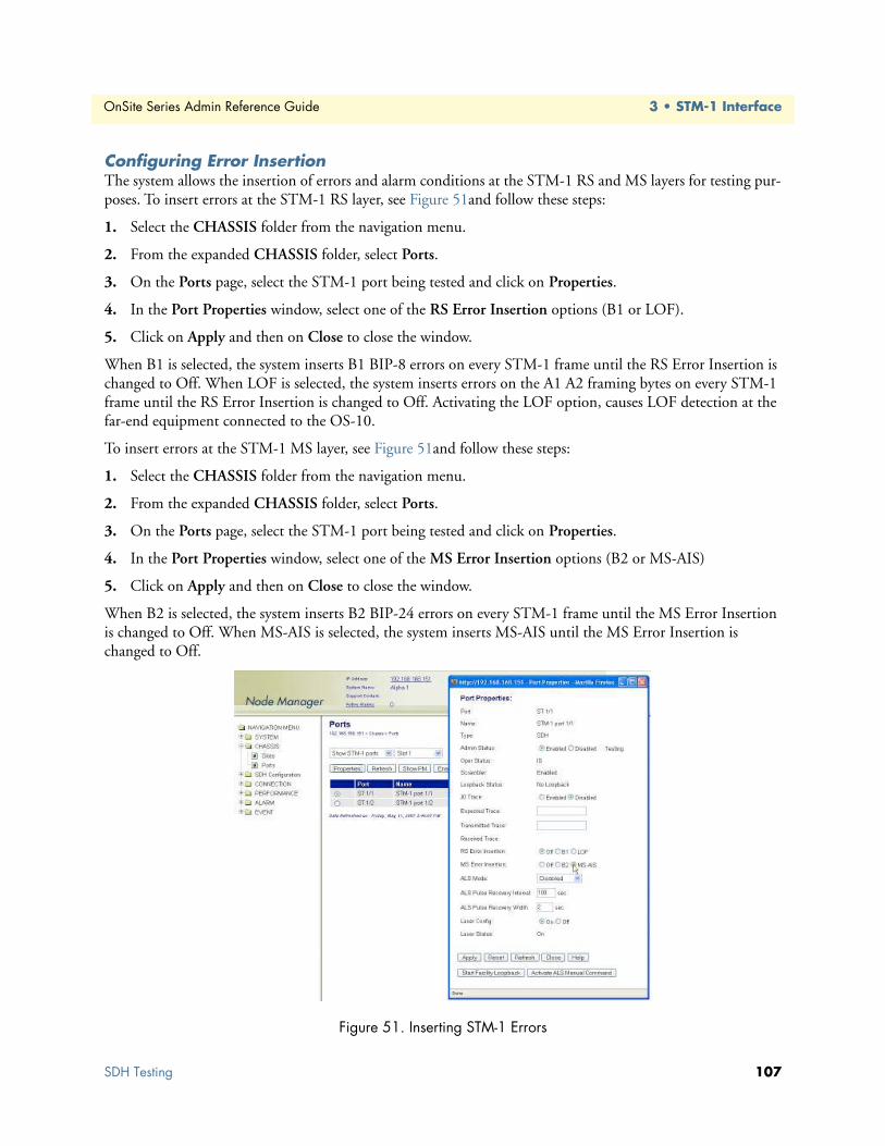
OnSite Series Admin Reference Guide 3 • STM-1 Interface
Configuring Error InsertionThe system allows the insertion of errors and alarm conditions at the STM-1 RS and MS layers for testing pur-poses. To insert errors at the STM-1 RS layer, see Figure 51and follow these steps:
1. Select the CHASSIS folder from the navigation menu.
2. From the expanded CHASSIS folder, select Ports.
3. On the Ports page, select the STM-1 port being tested and click on Properties.
4. In the Port Properties window, select one of the RS Error Insertion options (B1 or LOF).
5. Click on Apply and then on Close to close the window.
When B1 is selected, the system inserts B1 BIP-8 errors on every STM-1 frame until the RS Error Insertion is changed to Off. When LOF is selected, the system inserts errors on the A1 A2 framing bytes on every STM-1 frame until the RS Error Insertion is changed to Off. Activating the LOF option, causes LOF detection at the far-end equipment connected to the OS-10.
To insert errors at the STM-1 MS layer, see Figure 51and follow these steps:
1. Select the CHASSIS folder from the navigation menu.
2. From the expanded CHASSIS folder, select Ports.
3. On the Ports page, select the STM-1 port being tested and click on Properties.
4. In the Port Properties window, select one of the MS Error Insertion options (B2 or MS-AIS)
5. Click on Apply and then on Close to close the window.
When B2 is selected, the system inserts B2 BIP-24 errors on every STM-1 frame until the MS Error Insertion is changed to Off. When MS-AIS is selected, the system inserts MS-AIS until the MS Error Insertion is changed to Off.
Figure 51. Inserting STM-1 Errors
SDH Testing 107

OnSite Series Admin Reference Guide 3 • STM-1 Interface
Virtual Concatenation (VCAT)The system supports the connection of Ethernet traffic over SDH using virtual concatenation (VCAT) groups, in accordance with ITU-T Recommendation G.707. The following section provides the procedures for provi-sioning and monitoring virtual VCAT groups (VCGs).
NOTE: You must create a VCG before connecting Ethernet ports to the STM-1 port.
Introduction to VCATVCAT groups are flexible TDM payload channels for Ethernet traffic. The standard notation for a VCG is VC-n-Xv, where “VC-n” is the capacity of the constituent members, and “X” is the number of members. The letter “v” indicates that the “X” members form a virtual concatenation group. The total capacity of the VC-n-Xv is thus X * VC-n. A VC-3-2v supports a full-rate Fast Ethernet service at 100 Mbit/s. A VCG with a single VC-3 member (that is, a VC-3-1v) supports the transport of fractional Fast Ethernet services at 50 Mbit/s.
For finer bandwidth provisioning, the size of a VC-12-Xv can be adjusted in 2-Mbit/s increments up to the required bandwidth. A VC-12-5v, for instance, supports a full-rate Ethernet 10BASE-T service at 10 Mbit/s. A VC-12-50v supports a full-rate Fast Ethernet service at 100 Mbit/s.
VCAT Group Features for the OS1052The OS1052 base system contains two Ethernet ports and supports the creation of up to 2 VCGs at the VC-3 and VC-12 levels (one VCG for each port). The two VCGs can be combined in various ways. Table 39 pro-vides the provisioning rules for the creation of VCGs on the OS1052 base system (slot 1).
The OS1052 supports additional VCGs through the use of the high-density Ethernet (HD-ENET) expansion module. In contrast to the Ethernet ports on the base system, the HD-ENET module provides full flexibility in the creation of VCGs for slots 2 and 3. The module provides full access to all the available TU-12 and TU-3 time slots in the system.
The HD-ENET module supports two configuration modes: VCG 16 and VCG 8. In VCG 16 mode, you can create up to 16 VCGs using the available time slots. In this mode, the maximum size of a VCG group is lim-ited to 18 VC-12 members. Use this mode when you require provisioning of a large number of Ethernet ser-vices with with reduced bandwidth requirements. In VCG 8 mode, you can create up to 8 VCGs with a maximum of 50 VC-12 members.
The maximum number of VCGs depends on the number of available time slots on the STM-1 and size of the existing VCGs. For example, if the STM-1 is configured with 63 TU-12 time slots (and assuming that none of the time slots is currently in use), the module can support 16 VCGs: 15 VC-12-4v and one VC-12-1v. On the other hand, if you configure a large VCG, such as a VC-12-60v, only three time slots remain for a single VC-
Table 39. VCG Provisioning Rules for OS1052 Base System (Slot 1)
VCG Combination Group 1 Group 2 Restrictions
1 VC-3-1v VC-3-1v None2 VC-3-1v VC-12-Xv X = 1 to 123 VC-3-2v VC-3-1v None4 VC-3-2v VC-12-Xv X = 1 to 125 VC-12-Xv VC-12-Yv X + Y should be less than or equal to 16,
while X or Y does not exceed 12
Virtual Concatenation (VCAT) 108

OnSite Series Admin Reference Guide 3 • STM-1 Interface
12-3v or 3 VC-12-1v. Any combination of VCG size and number is possible, as long as the total number of VC-3 and VC-12 paths in all VCGs in a module do not exceed the available number of time slots.
The system rejects any attempt to create VCGs that do not meet these provisioning rules.
VCAT Group Features for the OS1063The OS1063 does not contain Ethernet ports in slot 1 (the base system). Therefore, the OS1063 supports VCGs only through the use of the high-density Ethernet (HD-ENET) expansion module in slots 2 and 3.
Summary of VCAT Group Features for the OS-10-Series SystemsTable 40 provides a summary of the VCAT features for the OS1052 using slots 1-3 (base and expansion slots) and for the OS1063 using slots 2-3 (expansion slots only).
Note VCG support in slots 2 and 3 requires the use of the high-density Ethernet (HD-ENET) module. See chapter 13 for details about the installation and operation of this module.
GFP Packet Transport ConsiderationsThe system removes the inter-packet gaps (IPG) between incoming Ethernet frames before encapsulating the frames into a VCG using generic framing procedure (GFP). This removal of the IPG results in more efficient use of the VCG capacity. The system reinserts the IPG for outgoing frames sent over the Ethernet ports.
When the average rate of the incoming Ethernet port traffic exceeds the allocated VCG capacity, it causes an internal buffer overflow condition with a resulting drop in packets. This overflow condition results in the gen-eration of an Ethernet Buffer Overflow alarm. The system buffers, however, provide sufficient capacity to absorb short-term bursts above the allocated capacity.
Note If packet congestion occurs, flow control at the Ethernet and TCP levels automatically reduce the incoming packet rate to match the provisioned TDM channel bandwidth.
VCG NotationThe system uses the following notation to identify VCGs. VCG:slot-number. For example, VCG:3-10 refers to the tenth VCG on slot 3.
Note You can connect only Ethernet traffic between ports and VCGs that reside on the same slot. For example, only the Ethernet ports on slot 2 have access to the VCGs that you create on that slot.
Table 40. Summary of VCAT Features for the OS-10-Series
VC-3-Xv VC-12-Xv
Slot ID Slot Type MaximumNo. of VCGs
ProvisioningRange
Bandwidth(Mbit/s)
ProvisioningRange
Bandwidth(Mbit/s)
1 Base (OS1052 only)
2 X = 1 to 2 48.96 to 97.92 X = 1 to 12 2.176 to 26.112
2 or 3 Expansion (HD-ENET)
8 X = 1 to 2 48.96 to 97.92 X = 1 to 50 2.176 to 108.816 X = 1 to 2 48.96 to 97.92 X = 1 to 18 2.176 to 39.168
Virtual Concatenation (VCAT) 109

OnSite Series Admin Reference Guide 3 • STM-1 Interface
Differential DelayBecause VCG members may travel through separate VC-n connection paths across the SDH network, it is pos-sible for individual members to arrive at the far end of the VCG connection with different delays relative to each other. These delays are compensated using internal “differential delay” buffers. These buffers realign the incoming VCG members to a common phase prior to extracting the Ethernet traffic from the combined pay-load capacity.
Table 41 provides the maximum differential delay that the system can compensate for different types of ports. The system generates a loss of alignment (LOA) alarm if the VCAT processor cannot reconstruct the VCG because the VCG members exceed the differential delay allocation for the system.
Note This differential delay allocation allows the transport of Ethernet sig-nals between two OS-10 nodes using transcontinental and transoce-anic links.
Creating a VCGThis section provides the procedures for the creation of VCGs at the VC-3 and VC-12 levels.
To create a VCG at the VC-3 level, see Figure 52 on page 113 and follow these steps:
1. Select the SDH Configuration folder from the navigation menu.
2. From the expanded SDH Configuration folder, select VCAT Groups.
3. On the VCAT Groups page, click on Create VCAT Group.
4. Select the slot in which you want to create the VCG using the Slot scroll-down button.
Note The system displays the entries for slots 2 and 3 only when these slots are provisioned with the HD-ENET module.
• The system assigns a unique VCG ID for the slot after creation of the VCG. This ID is indicated in the VCG ID field. The VCG ID contains the slot number and VCG number for that slot. The notation for the VCG ID is as follows: VCG:slot-number.
• As an option, you may choose to identify the newly created VCG with a name. Type the VCG name in the Name field or leave it blank.
5. Set the VCG mode for the HD-ENET module, if present in slot 2 or 3.
Note The system only allows setting the VCG mode when the HD-ENET module contains no VCGs. Setting the VCG mode is not applicable for the base system ports in slot 1.
Table 41. Differential Delay Support
Ethernet Ports on the . . . Maximum Differential Delay
Base system ±256 msecHD-ENET module ±128 msec
Virtual Concatenation (VCAT) 110

OnSite Series Admin Reference Guide 3 • STM-1 Interface
6. To enable the LCAS function for the VCG, set LCAS to Enabled. Otherwise, continue with Step 7.
Note The system supports the enabling of the LCAS function only in slots 2 and 3, when the slots contain the HD-ENET module.
With the LCAS function enabled, you may configure the LCAS Hold-Off Time and the LCAS WTR Time to different values other than the default value of 0.
The LCAS Hold-Off time is the amount of time the LCAS processor waits before the temporary removal of a member from the VCG after reception of an MST (Sk) = FAIL for that member. The LCAS processor removes the member from the VCG only if the member remains in the failed condition at the time the hold-off time expires. The timer is set in multiples of 100 msec, from 0 to 10 sec (0 sec as default).
The LCAS WTR (wait-to-restore) time is the amount of time the LCAS processor waits before the system rein-serts a failed member back into a VCG after the MST (Sk) for that member changes from FAIL back to OK. The provisioning range for the LCAS WTR time is 0 to 12 minutes, and is set in 1 minute increments (0 min-utes as default).
7. In the Create VCAT Group window, set Level to VC-3 to create a VC-3-Xv.
8. In the Create VCAT Group window, select the No. of Members for the new VCG using the scroll-down button.
At this point, the system provides a list of available TU-3 time slots in the STM-1 using the SDH indexing scheme.
Note When the system is configured for Linear 1+1 MSP or SNCP opera-tion, the list includes only the TU-3 time slots for STM-1 port 1 (ST:1/1). However, when both ports are unprotected, the list includes the available time slots for both ports (ST:1/1 and ST:1.2).
9. In the Create VCAT Group window, select the TU-3 Member Locations for each VCG member.
The system highlights default member locations according to the number of VCG members that you select. You may, however, choose TU-3 time slots other than the default locations.
To select more than one member from the list, click on individual entries while pressing the Ctrl key. (The sys-tem highlights any entry that you select from the list. You can select any entry from the list, whether the mem-ber locations are contiguous or not.)
Note To select a range of consecutive entries from the list, select the first entry and then select the last entry while pressing the Shift key.
• Use the Reset button to restore the window to the default member location.
Make sure that the HD-ENET modules in your OS-10 system sup-port the required firmware revision for the use of the LCAS func-tion.
CAUTION
Virtual Concatenation (VCAT) 111

OnSite Series Admin Reference Guide 3 • STM-1 Interface
• Make sure that the number of selected entries from the list matches the No. of Members before proceeding with Step 8; otherwise, the system rejects the creation of the VCG.
10. Click on Apply to initiate the creation of the VCG.
At this point, the VCAT Groups page displays all current VCAT groups in the system, including the newly cre-ated VCG. The table contains a separate entry for each provisioned VCG. Each entry contains a summary of the VCG properties, including the VCAT Group ID, VCG Size, and Name. The table entry also contains the Admin Status and Oper Status of the VCG and whether or not SNCP protection is enabled or disabled. The SNCP Mode and Primary Path for the VCG are also displayed.
Note The VCG Admin Status changes from Disabled to Enabled when you connect an Ethernet port to the VCG.
• The Oper Status indicates that the VCG is IS (in service) when the Admin Status is Enabled and no VCG alarms are present. Other-wise, the Oper Status indicates OOS (out of service).
• When you create a VCG at VC-3 level, the system reserves the TU-3 time slots that you assign for each VCG member. You cannot use these time slots to create another VCG unless you delete the first VCG. Each TU-3 sends the unequipped signal until the moment that you create a connection between an Ethernet port and the VCG. (Refer to §11.3 for details.) At that point, the system equips each VC-3 for carrying GFP payload.
The Create VCAT Group window closes automatically after the system completes the creation of the VCG. For VCGs with a large number of members, the system may take a few seconds to create the VCG and close the window. Closing the window man-ually before.the process is complete may cause an error or par-tial creation of the new VCG (that is, the new VCG contains a reduced number of members.)
CAUTION
Virtual Concatenation (VCAT) 112

OnSite Series Admin Reference Guide 3 • STM-1 Interface
Figure 52. Provisioning a VCG at the VC-3 Level
To configure the SNCP settings of a VCG, see Figure 53 on page 114 and follow these steps:
1. On the VCAT Groups page, select the table entry containing the required VCG and click on Properties.
At this point, if the VCG is connected to an STM-1 port pair that is configured for operation in SNCP mode, the VCAT Group Properties window contains the SNCP path properties for the VCG. You can set the SNCP path properties in accordance with the descriptions in Table 54.
2. In the VCAT Group Properties window, set SNCP to Enabled.
Note The SNCP path properties for the VCG apply to all members of the VCG. The system ensures that the SNCP path properties of all VCG members remain the same.
The VCAT Group Properties window also contains the SNCP path status for all the VCG members (see Table 55 for a description of the table fields and entries). To activate any of the external commands for SNCP path switching for an individual VCG member, select the table entry for the member and click on SNCP Sta-tus/Command.
Virtual Concatenation (VCAT) 113

OnSite Series Admin Reference Guide 3 • STM-1 Interface
Figure 53. Configuring the SNCP Settings of a VCG at the VC-3 Level
To view and configure the properties of a VCG member, see Figure 54 on page 115 and follow these steps:
1. On the VCAT Groups page, select the table entry containing the required VCG and click on Properties.
2. In the VCAT Group Properties window, select one of the VCG members and click on TP Properties.
At this point, the system displays the current VC-3 TP settings for the selected VCG member.
To configure the J1 trace message on the VC-3, continue with Step 3.
Note To configure the TP properties of a VCG member, the VCG must be connected to an Ethernet port .
3. In the TP Properties window, set the J1 Trace to Enabled.
– Set TIM Monitor to Enabled, if you wish to detect trace identifier mismatch (TIM) defects for the VC-3 TP using the J1 trace.
– Set TIM Action to Enabled, if you wish to generate a consequent action (AIS downstream and LP-RDI upstream) upon detection of a TIM defect for the VC-3 TP using the J1 trace.
4. Type the Expected Trace and the Transmitted Trace using up to 15 ASCII characters for each field.
Note The system inserts the transmitted trace into the outgoing J1 byte for the VC-3 TP. The system does not allow enabling the J1 trace with the expected trace and transmitted trace fields empty. The system dis-plays the Received Trace message if any is being received from the incoming J1 byte for this VC-3 TP.
Virtual Concatenation (VCAT) 114

OnSite Series Admin Reference Guide 3 • STM-1 Interface
To configure the error insertion features for the TP, continue with Step 5; otherwise, go directly to Step 6 to complete this task.
5. In the TP Properties window, select one of the Error Insertion options (B3 or TU-AIS).
Note When B3 is selected, the system inserts B3 BIP-8 errors on every frame of the VC-3 TP until the Error Insertion is changed to Off.
Note When TU-AIS is selected, the system inserts TU-AIS on the TU-3 until the Error Insertion is changed to Off. Activating the TU-AIS option causes TU-AIS detection at the farend equipment connected to the OS-10 system.
6. Click on Apply and then on Close to close the TP Properties window.
7. Click on Close to close the VCAT Group Properties window.
Figure 54. Configuring the Properties of a VC-3 VCG Member
Virtual Concatenation (VCAT) 115

OnSite Series Admin Reference Guide 3 • STM-1 Interface
To create a VCG at the VC-12 level, see Figure 55 on page 118 and follow these steps:
1. Select the SDH Configuration folder from the navigation menu.
2. From the expanded SDH Configuration folder, select VCAT Groups.
3. On the VCAT Groups page, click on Create VCAT Group.
4. Select the slot in which you want to create the VCG using the Slot scroll-down button.
Note The system displays the entries for slots 2 and 3 only when these slots are provisioned with the HD-ENET module.
• The system assigns a unique VCG ID for the slot after creation of the VCG. This ID is indicated in the VCG ID field. The VCG ID contains the slot number and VCG number for that slot. The notation for the VCG ID is as follows: VCG:slot-number.
• As an option, you may choose to identify the newly created VCG with a name. Type the VCG name in the Name field or leave it blank.
5. Set the VCG mode for the HD-ENET module, if present in slot 2 or 3.
Note The system only allows setting the VCG mode when the HD-ENET module contains no VCGs. Setting the VCG mode is not applicable for the base system ports in slot 1.
6. To enable the LCAS function for the VCG, set LCAS to Enabled. Otherwise, continue with Step 7.
Note The system supports the enabling of the LCAS function only in slots 2 and 3, when the slots contain the HD-ENET module.
With the LCAS function enabled, you may configure the LCAS Hold-Off Time and the LCAS WTR Time to different values other than the default value of 0.
The LCAS Hold-Off time is the amount of time the LCAS processor waits before the temporary removal of a member from the VCG after reception of an MST (Sk) = FAIL for that member. The LCAS processor removes the member from the VCG only if the member remains in the failed condition at the time the hold-off time expires. The timer is set in multiples of 100 msec, from 0 to 10 sec (0 sec as default).
The LCAS WTR (wait-to-restore) time is the amount of time the LCAS processor waits before the system rein-serts a failed member back into a VCG after the MST (Sk) for that member changes from FAIL back to OK. The provisioning range for the LCAS WTR time is 0 to 12 minutes, and is set in 1 minute increments (0 min-utes as default).
Make sure that the HD-ENET modules in your OS-10 system sup-port the required firmware revision for the use of the LCAS func-tion.
CAUTION
Virtual Concatenation (VCAT) 116

OnSite Series Admin Reference Guide 3 • STM-1 Interface
7. In the Create VCAT Group window, set Level to VC-12 to create a VC-12-Xv.
8. In the Create VCAT Group window, select the No. of Members for the new VCG using the scroll-down button.
At this point, the system provides a list of available TU-12 timeslots in the STM-1 using the SDH indexing scheme. By default, the system displays the TU-12 timeslots in logical sequence order. To display the timeslots in physical order, set the Member Sequencing Type to Physical order.
Note With the LCAS function disabled, the system assigns the sequence number for VCG members strictly in accordance to the order in which the timeslots appear on the list. For VCG interworking pur-poses with other equipment, make sure that the member sequencing type is the same for both the OS-10 and the other equipment.
• When the system is configured for Linear 1+1 MSP or SNCP operation, the list includes only the TU-12 time slots for STM-1 port 1 (ST:1/1). However, when both ports are unprotected, the list includes the available time slots for both ports (ST:1/1 and ST:1.2).
9. In the Create VCAT Group window, select the TU-12 Member Locations for each VCG member.
The system highlights default member locations according to to the number of VCG members that you select. You may, however, choose TU-12 time slots other than the default locations.
To select more than one member from the list, click on individual entries while pressing the Ctrl key. (The sys-tem highlights any entry that you select from the list. You can select any entry from the list, whether the mem-ber locations are contiguous or not.)
Note To select a range of consecutive entries from the list, select the first entry and then select the last entry while pressing the Shift key.
• Use the Reset button to restore the window to the default configu-ration of five members.
• Make sure that the number of selected entries from the list matches the No. of Members before proceeding with Step 8; otherwise, the system rejects the creation of the VCG.
10. Click on Apply to initiate the creation of the VCG.
The Create VCAT Group window closes automatically after the system completes the creation of the VCG. For VCGs with a large number of members, the system may take a few seconds to create the VCG and close the window. Closing the window man-ually before.the process is complete may cause an error or par-tial creation of the new VCG (that is, the new VCG contains a reduced number of members.)
CAUTION
Virtual Concatenation (VCAT) 117
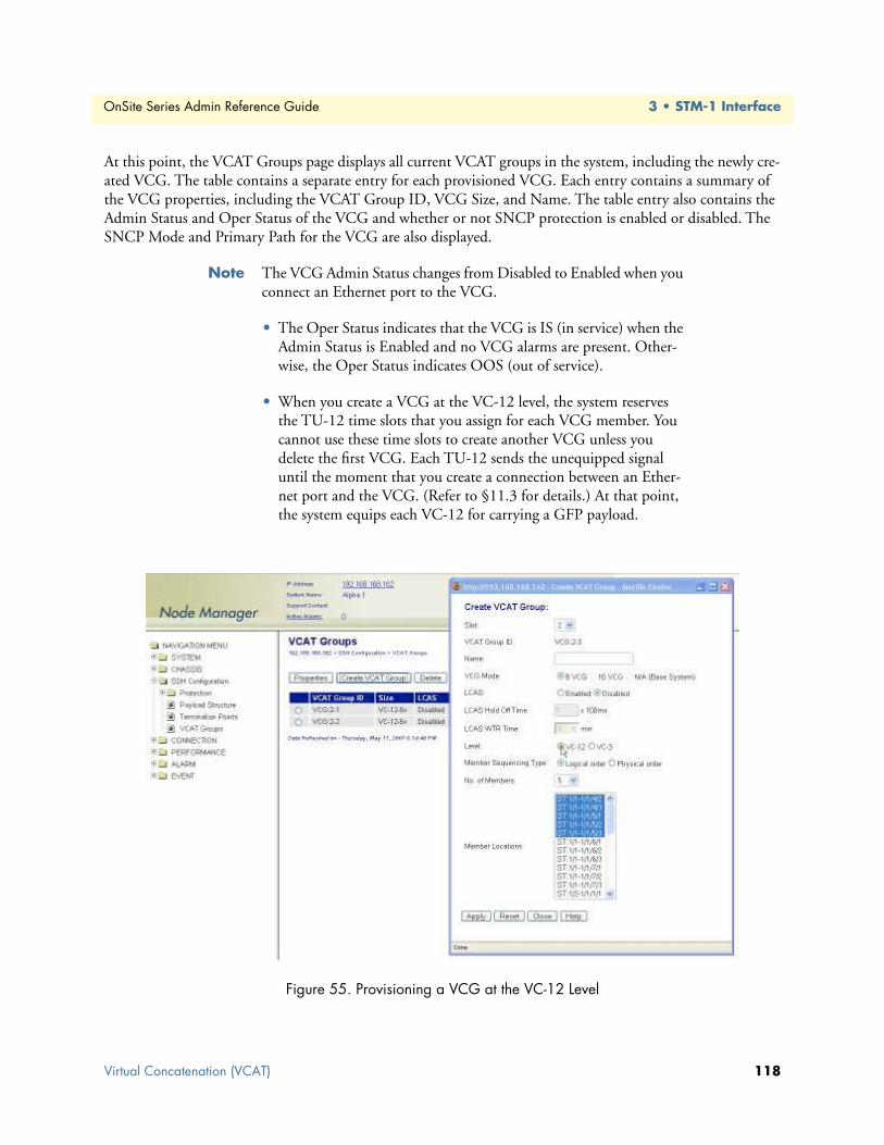
OnSite Series Admin Reference Guide 3 • STM-1 Interface
At this point, the VCAT Groups page displays all current VCAT groups in the system, including the newly cre-ated VCG. The table contains a separate entry for each provisioned VCG. Each entry contains a summary of the VCG properties, including the VCAT Group ID, VCG Size, and Name. The table entry also contains the Admin Status and Oper Status of the VCG and whether or not SNCP protection is enabled or disabled. The SNCP Mode and Primary Path for the VCG are also displayed.
Note The VCG Admin Status changes from Disabled to Enabled when you connect an Ethernet port to the VCG.
• The Oper Status indicates that the VCG is IS (in service) when the Admin Status is Enabled and no VCG alarms are present. Other-wise, the Oper Status indicates OOS (out of service).
• When you create a VCG at the VC-12 level, the system reserves the TU-12 time slots that you assign for each VCG member. You cannot use these time slots to create another VCG unless you delete the first VCG. Each TU-12 sends the unequipped signal until the moment that you create a connection between an Ether-net port and the VCG. (Refer to §11.3 for details.) At that point, the system equips each VC-12 for carrying a GFP payload.
Figure 55. Provisioning a VCG at the VC-12 Level
Virtual Concatenation (VCAT) 118

OnSite Series Admin Reference Guide 3 • STM-1 Interface
To view and configure the properties of a VC-12 VCG member, see Figure 56 on page 120 and follow these steps:
1. On the VCAT Groups page, select the table entry containing the required VCG and click on Properties.
2. In the VCAT Group Properties window, select one of the VCG members and click on TP Properties.
At this point, the system displays the current VC-12 TP settings for the selected VCG member.
To configure the J2 trace message on the VC-12, continue with Step 3.
Note To configure the TP properties of a VCG member, the VCG must be connected to an Ethernet port.
3. In the TP Properties window, set the J2 Trace to Enabled.
– Set TIM Monitor to Enabled, if you wish to detect trace identifier mismatch (TIM) defects for the VC-12 TP using the J2 trace.
– Set TIM Action to Enabled, if you wish to generate a consequent action (AIS downstream and LP-RDI upstream) upon detection of a TIM defect for the VC-12 TP using the J2 trace.
4. Type the Expected Trace and Transmitted Trace using up to 15 ASCII characters for each field.
Note The system inserts the transmitted trace into the outgoing J2 byte for the VC-12 TP.
• The system does not allow enabling the J2 trace with the expected trace and transmitted trace fields empty.
• The system displays the Received Trace if any message is being received from the incoming J2 byte for this VC-12 TP.
To configure the error insertion features for the TP, continue with Step 5; otherwise, go directly to Step 6 to complete this task.
5. In the TP Properties window, select one of the Error Insertion options (V5-BIP-2 or TU-AIS).
Note When V5-BIP-2 is selected, the system inserts V5 BIP-2 errors on every frame of the VC-12 TP until the Error Insertion is changed to Off.
• When TU-AIS is selected, the system inserts TU-AIS on the TU-12 until the Error Insertion is changed to Off. Activating the TU-AIS option causes TU-AIS detection at the farend equipment con-nected to the OS-10.
6. Click on Apply and then on Close to close the TP Properties window.
7. Click on Close to close the VCAT Properties window.
Virtual Concatenation (VCAT) 119

OnSite Series Admin Reference Guide 3 • STM-1 Interface
Figure 56. Configuring the Properties of a VC-12 VCG Member
Removing a VCGTo remove an existing VCG, see Figure 52 on page 113 and follow these steps:
1. Select a VCG on the VCAT Groups page.
2. Click on Delete to remove the VCG.
At this point, the system removes the VCG and it is no longer displayed in the table.
Note The system automatically disables the VCG after its deletion. All con-stituent VCG members are also disabled and the system starts send-ing the unequipped signal over the TU time slots. The time slots are now available for other connections.
• The system displays an error message if you try to delete a VCG that supports an existing Ethernet port connection. You must first remove the connection before deleting the VCG.
Virtual Concatenation (VCAT) 120

OnSite Series Admin Reference Guide 3 • STM-1 Interface
Monitoring VCG AlarmsTable 42 provides a list of the VCG alarms that the system supports.
To display VCG alarms, if present, see Figure 41 on page 93and follow these steps:
1. Select the ALARM folder from the navigation menu.
2. From the expanded ALARM folder, select Show Active Alarms.
At this point, the Active Alarms page displays all active alarms in the system, including VCG alarms, if present. The table contains a separate entry for each active VCG alarm. Table 43 describes the fields for each VCG alarm entry.
Note The system automatically updates the Active Alarms page every 60 seconds. Click on Refresh if you need to update the table with the most recent active alarm information. Individual table entries auto-matically clear whenever previously active alarms are no longer present.
Table 44 provides a list of the GFP alarms that the system supports.
Table 42. VCG Alarms
Alarm Description Occurs when the VCAT Processor . . .
LOA Loss of Alignment Cannot assemble the concatenated payload because one or more VCG members exceed the differential delay allocation.
LOM Loss of Multiframe Loses synchronization from:MFI-1 or MFI-2 for any member of a VC-3-XvorMFAS or LO-VCAT multiframe for any member of a VC-12-Xv
SQM Sequence Indicator Mismatch Receives a sequence number different from the one provisioned for a VCG member.
Table 43. Table Entries for Active VCG Alarms
Table Entry for Active Alarms Field Value
Type VCG LOA, VCG LOM, or VCG SQMAlarm Raised Time Date and timeSeverity Critical, Major, Minor, or WarningDetailed Information Location of affected VCG (VCG:slot-number)
Table 44. GFP Alarms
Alarm Description Occurs when. . .
LFD Loss of Frame Delineation Multiple bit errors are detected in the Core Header by the cHECUPM User Payload Mismatch A mismatch occurs between the provisioned and received User Pay-
load Identifiers (UPIs) in the GFP payload type fieldEXM Extension Header Mismatch A mismatch occurs between the provisioned and received Extension
Header Identifiers (EXIs) in the GFP payload type field
Virtual Concatenation (VCAT) 121

OnSite Series Admin Reference Guide 3 • STM-1 Interface
Displaying the Alarm LogTo display historical alarms, including any VCG or GFP alarms if present, follow these steps:
1. Select the ALARM folder from the navigation menu.
2. From the expanded ALARM folder, select Show Alarm Log.
At this point, the Alarm Log page displays a list of the 50 most recent alarm messages. The system keeps up to 500 entries in the alarm log.
Note The alarm log is a FIFO (first-in fist-out) log.
Click on Last 50 Log Entries or Next 50 Log Entries to move around and display the entire contents of the log. Click on Clear Log if you wish to delete permanently the current log entries.
VCAT Group Performance MonitoringTable 45 provides a list of the near-end PM parameters that the system monitors for VCAT groups (VCGs).
To display current PM data for a VCG, see Figure 57 on page 123 and follow these steps:
1. Select the SDH Configuration folder from the navigation menu.
2. From the expanded SDH Configuration folder, select VCAT Groups.
3. On the VCAT Groups page, select the VCG for which you wish to display the PM counts and click on Show PM.
At this point, the VCAT Group Near-end PM page (see Figure 57) shows the near-end PM data for both the current 15-minute and 24-hour periods.
Note The PM data is not updated automatically as new events occur dur-ing the current 15-minute and 24-hour periods. Click on Refresh to update the tables with the most recent cumulative count for the cur-rent periods.
Continue with the steps that follow to display historical PM data.
Table 45. VCG PM Parameters
Parameter Description Definition
VCG BBE Background Block Error Count of BBE across all VCG membersVCG ES Errored Second Count of seconds in which an ES occurs on one or more VCG
members or in which the LOA, LOM, or SQM defect occursVCG SES Severely Errored Second Count of seconds in which an SES occurs on one or more
VCG members or in which the LOA, LOM, or SQM defect occurs
VCG UAS Unavailable Seconds Period of unavailable time that begins at the onset of 10 consecutive SESs
LOAS Loss of Alignment Seconds Count of seconds in which the LOA defect occursLOMS Loss of Multiframe Seconds Count of seconds in which the LOM defect occursSQMS Sequence Mismatch Seconds Count of seconds in which the SQM defect occurs
Virtual Concatenation (VCAT) 122

OnSite Series Admin Reference Guide 3 • STM-1 Interface
4. Click on Show Interval.
At this point, the VCAT Group Near-end PM page shows the near-end PM data for the following intervals:
• Current plus previous 95-by-15-minute intervals (24 hours total)
• Current plus previous day (2 days total)
Click on Refresh to update the tables with the most recent cumulative count for the current periods. This action updates only the first entry in the tables, which corresponds to the current measurement period.
Note The tables display Invalid under PM data when the data collected during a measurement period is considered invalid. The Interval Start Time also displays n/a (not available).
Figure 57. Displaying Current PM Data for VCGs
To display current and historical PM data for all VCGs in the system, see Figure 58 on page 124 and follow these steps:
1. Select the PERFORMANCE folder from the navigation menu.
2. From the expanded PERFORMANCE folder, select Counters.
3. From the expanded Counters folder, select SDH.
4. From the expanded SDH folder, select VCAT Groups.
At this point, the VCAT Group Near-end PM – Current 15 minutes page shows the near-end PM data for the current 15-minute period only.
Continue with the steps that follow to display historical PM data for both 15-minute and 24-hour periods.
5. Select a VCG and click on Show Interval.
Virtual Concatenation (VCAT) 123

OnSite Series Admin Reference Guide 3 • STM-1 Interface
Note The preceding notes for the VCAT Group Near-end PM page also apply to this procedure.
Figure 58. Displaying Current PM Data for All VCGs
To clear the current PM data for a VCG, see Figure 58 and follow this step:
1. On the VCAT Group Near-end PM page, select one of the VCG entries and use the Clear Counter Options... scroll-down button to select one of the available options for clearing the current 15-minute counter, 24-hour counter, or both.
Link Capacity Adjustment Scheme (LCAS)The system supports the use of the LCAS feature for VCGs in slots 2 and 3 only. (LCAS is not supported for VCGs is slot 1.) LCAS supports two basic functions:
• Hitless addition and deletion of VCG members: Dynamic adjustment of provisioned VCG bandwidth through manual commands issued from the OnSight Device Manager or the NMS.
• Temporary removal of failed VCG members: Automatic reduction of provisioned VCG bandwidth upon detection of failures in one or more VCG members. Maintains service connectivity over remaining non-failed VCG members. VCG bandwidth automatically restored as failed members return back to normal. Does not require intervention through the Device Manager or NMS.
To configure a VCG for LCAS operation, follow these steps:
1. In the Create VCAT Group window (see Figure 62), set LCAS to Enabled and click on Apply.
At this point, the VCG is enabled for LCAS operation.
Each VCG member has two LCAS components: a source (So) and a sink (Sk) component. When a VCG is first enabled for LCAS operation, the system automatically enables the LCAS (Sk) component for all current VCG members. At this point, the members begin processing and acting upon LCAS control words received at
Virtual Concatenation (VCAT) 124

OnSite Series Admin Reference Guide 3 • STM-1 Interface
the sink side of the VCG. However, the system requires manual activation of the LCAS (So) component for individual VCG members. Upon activation of the source component, the selected members begin the genera-tion of LCAS control words and become part of the composite VCG payload capacity at the source side of the VCG.
Note Individual VCG members use the LCAS control packet to send and receive LCAS signaling information. The LCAS control packet con-tains the control (CTRL) word and the member status (MST) infor-mation for each VCG member. For VCGs at the VC-12 level, the LCAS control packet is located in the K4 byte bit 2 over multiple frames; and for VCGs at the VC-3 level, it is located in the H4 byte over multiple frames.
Table 46 provides a list of the LCAS control (CTRL) words that can be sent over LCAS control packets. MST has only two states: OK and FAIL.
To create and add new members into the VCG, follow these steps:
1. On the VCAT Groups page, select the LCAS-enabled VCG that you wish to configure and click on Prop-erties.
2. In the VCAT Group Properties window, click on VCG Member Management.
To provision additional TU timeslots for inclusion into the VCG, see Figure 59 on page 126 and continue with the rest of step 2 below. Otherwise, if the VCG already contains all the required member timeslots, con-tinue with Step 3.
– In the VCG Member Management window, click on Create VCG Member.
– In the Create New Member in VCG window, select the Member Locations for each new VCG member.
The system highlights default member locations according to the number of VCG members that you select. You may, however, choose TU timeslots other than the default locations.
To select more than one member from the list, click on individual entries while pressing the Ctrl key. (The sys-tem highlights any entry that you select from the list. You can select any entry from the list, whether the mem-ber locations are contiguous or not.)
To select a range of consecutive entries from the list, select the first entry and then select the last entry while pressing the Shift key. Use the Reset button to restore the window to the default member location.
Table 46. LCAS Control (CTRL) Words
Command Indicates . . .
FIXED This end uses fixed bandwidth (non-LCAS mode)ADD This member is about to be added to the group
NORM Normal transmissionEOS End of sequence and normal transmissionIDLE This member is not part of the group or about to be removedDNU Do Not Use (the payload); the Sk side reported FAIL status
Virtual Concatenation (VCAT) 125

OnSite Series Admin Reference Guide 3 • STM-1 Interface
Note Make sure that the number of selected entries from the list matches the No. of Members before proceeding; otherwise, the system rejects the creation of new VCG members.
– Click on Add and then on Close to close the Create New Member in VCG window.
– Click on Refresh LCAS Status in the VCG Member Management window.
At this point, the newly-created members appear as part of the VCG in the VCG Member Management win-dow. Also, the new VCG members begin processing and acting upon LCAS control words received at the sink side of the VCG.
Figure 59. Creating New VCG Members
3. In the VCG Member Management window, use the selector box to indicate the VCG members that you wish to include in the payload capacity at the source side of the VCG (see Figure 67).
At this point, CTRL (So) is IDLE for all inactive VCG members at the source side of the VCG. Also, the sequence (SQ) number for these members displays the maximum value of 63 for VCGs at the VC-12 level, and 255 for VCGs at the VC-3 level.
To select all VCG member entries in the table, click on Select All at the botton of the table. You can also click on Deselect All to clear all the selection boxes.
Note To ensure successful addition of new VCG members, it is necessary that there is SDH path connectivity between the timeslots that con-tain the new members on both sides of the endto- end VCG connec-tion.
4. Click on the Add to LCAS (So) button (see Figure 60 on page 127).
At this point, LCAS (So) for the selected VCG members changes from Inactive to Active, and the selected members begin sending ADD in the transmit control word; that is, CTRL (So) = ADD. Also, the system auto-
Virtual Concatenation (VCAT) 126

OnSite Series Admin Reference Guide 3 • STM-1 Interface
matically sets and displays the sequence (SQ) number for all active members at the source side of the VCG. For a VC-n-Xv, the SQ number for all members ranges from 0 to X-1.
Note The system sends the ADD control word in sequencial manner for each new active member on the source side of the VCG. That is, the first new active member sends ADD while the rest of the members remain IDLE. When the MST (Sk) for a new active member changes from FAIL to OK, CTRL (So) changes from ADD to NORM (or to EOS for the current last member). This change indicates the success-ful addition of the member into the composite VCG payload capacity at the source side of the VCG and the start of transmission of Ether-net packets over that member. In the same manner, the system con-tinues with the automatic addition of new active members – one by one – until all new active members become part of the VCG at the source side.
Figure 60. Adding VCG Members to the LCAS (So) Function
5. Check that CTRL (So) = NORM (or EOS if a member is the last in the sequence) and MST (Sk) = OK for all new active members at the source side of the VCG (see Figure 61 on page 128).
Note Click on Refresh LCAS Status to display the current value for each of the LCAS parameters. (You may need to continue refreshing the LCAS status until the system displays a status change for all selected members.)
During the sequential addition process, the system skips any particular member that cannot be added unto the VCG at the source side because of a path connectivity or LCAS signaling failure. Failed active members – that is, members with CTRL (So) = ADD and MST (Sk) = FAIL – continue sending ADD until you select the
Virtual Concatenation (VCAT) 127

OnSite Series Admin Reference Guide 3 • STM-1 Interface
members and press the Remove from LCAS button. This action changes the CTRL (So) word back to IDLE and stops the addition process for the selected member.
6. Click on Close to close the VCG Member Management window.
The Size field on the VCAT Groups page reflects the new size of the VCG after the creation of the VCG mem-bers.
Figure 61. Completion of the Add to LCAS (So) Operation
To remove and delete members from the VCG, follow these steps:
1. On the VCAT Groups page, select the LCAS-enabled VCG that you wish to configure and click on Prop-erties.
2. In the VCAT Group Properties window, click on VCG Member Management.
3. In the VCG Member Management window, use the selector box to indicate the VCG members that you wish to remove from the source side of the VCG.
To select all VCG member entries in the table, click on Select All at the botton of the table. You can also click on Deselect All to clear all the selection boxes.
At this point, CTRL (So) is NORM (or EOS for the last active member) for all active VCG members at the source side of the VCG. This control word indicates that the VCG members are configured for carrying Ether-net traffic in the So to Sk direction. Also, the SQ number for all active VCG members at the source side should range from 0 to X-1.
4. Click on the Remove from LCAS (So) button.
LCAS operations are unidirectional. This means that adding or removing VCG members in both directions of transmission requires repeating the “add” or “remove” procedure twice – once for each direction of transmission.CAUTION
Virtual Concatenation (VCAT) 128
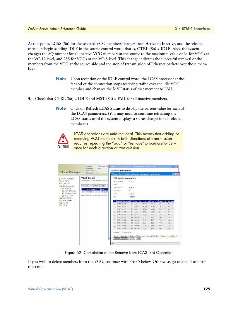
OnSite Series Admin Reference Guide 3 • STM-1 Interface
At this point, LCAS (So) for the selected VCG members changes from Active to Inactive, and the selected members begin sending IDLE in the source control word; that is, CTRL (So) = IDLE. Also, the system changes the SQ number for all inactive VCG members at the source to the maximum value of 64 for VCGs at the VC-12 level, and 255 for VCGs at the VC-3 level. This change indicates the successful removal of the members from the VCG at the source side and the stop of transmission of Ethernet packets over those mem-bers.
Note Upon reception of the IDLE control word, the LCAS processor at the far end of the connection stops receiving traffic over the idle VCG member and changes the MST status of that member to FAIL.
5. Check that CTRL (So) = IDLE and MST (Sk) = FAIL for all inactive members.
Note Click on Refresh LCAS Status to display the current value for each of the LCAS parameters. (You may need to continue refreshing the LCAS status until the system displays a status change for all selected members.)
Figure 62. Completion of the Remove from LCAS (So) Operation
If you wish to delete members from the VCG, continue with Step 5 below. Otherwise, go to Step 6 to finish this task.
LCAS operations are unidirectional. This means that adding or removing VCG members in both directions of transmission requires repeating the “add” or “remove” procedure twice – once for each direction of transmission.CAUTION
Virtual Concatenation (VCAT) 129
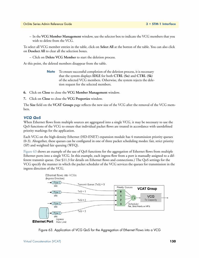
OnSite Series Admin Reference Guide 3 • STM-1 Interface
– In the VCG Member Management window, use the selector box to indicate the VCG members that you wish to delete from the VCG.
To select all VCG member entries in the table, click on Select All at the botton of the table. You can also click on Deselect All to clear all the selection boxes.
– Click on Delete VCG Member to start the deletion process.
At this point, the deleted members disappear from the table.
Note To ensure successful completion of the deletion process, it is necessary that the system displays IDLE for both CTRL (So) and CTRL (Sk) of the selected VCG members. Otherwise, the system rejects the dele-tion request for the selected members.
6. Click on Close to close the VCG Member Management window.
7. Click on Close to close the VCG Properties window.
The Size field on the VCAT Groups page reflects the new size of the VCG after the removal of the VCG mem-bers.
VCQ QoSWhen Ethernet flows from multiple sources are aggregated into a single VCG, it may be necessary to use the QoS functions of the VCG to ensure that individual packet flows are treated in accordance with userdefined priority markings for the application.
Each VCG on the high-density Ethernet (HD-ENET) expansion module has 4 transmission priority queues (0-3). Altogether, these queues can be configured in one of three packet scheduling modes: fair, strict priority (SP) and weighted fair queuing (WFQ).
Figure 63 shows an example of the use of QoS functions for the aggregation of Ethernet flows from multiple Ethernet ports into a single VCG. In this example, each ingress flow from a port is manually assigned to a dif-ferent transmit queue. (See §11.3 for details on Ethernet flows and connections.) The QoS settings for the VCG specify the manner in which the packet scheduler of the VCG services the queues for transmission in the ingress direction of the VCG.
Figure 63. Application of VCG QoS for the Aggregation of Ethernet Flows into a VCG
Virtual Concatenation (VCAT) 130

OnSite Series Admin Reference Guide 3 • STM-1 Interface
To configure the QoS functions for a VCG, see Figure 64 and follow these steps:
1. Select the SDH Configuration folder from the navigation menu.
2. From the expanded SDH Configuration folder, select VCAT Groups.
3. On the VCAT Groups page, select the VCG being configured and click on Properties.
Note Only VCGs where the HD-ENET module is installed in slot 2 or 3 support configuration of the VCG QoS functions.
4. In the VCAT Group Properties window, click on QoS.
5. In the VCG QoS Properties window set Queuing to Custom if you wish to configure the packet scheduler of the VCG for operation in Strict Priority or WFQ mode.
To configure the packet scheduler in Strict Priority mode, continue with the first dash below; otherwise, for operation in WFQ mode, skip to the second dash.
– To configure the packet scheduler of the VCG in Strict Priority mode, set Queue 0 Mode to Strict Pri-ority. This change applies to all queues. (Strict Priority is the default setting for all queues.) Continue with Step 6 to complete this task.
In Strict Priority mode, the packet scheduler gives strict preference to packets in higher priority queues over packets in lower priority queues, regardless of the packet occupancy of individual queues. Among the four transmit queues, Queue 3 is the queue with the highest priority and Queue 0 is the queue with the lowest pri-ority.
– To configure the packet scheduler of the VCG in WFQ mode, set Queue 0 Mode to WFQ. This change applies to all queues. Continue with Step 6 to complete this task.
In WFQ mode, the packet scheduler services the queues in accordance to a weight that you assign for each queue. The system requires that the sum of the weights for all four queues adds up to 100 percent.
6. Click on Apply and then on Close to close the VCG QoS Properties window.
7. Click on Close to close the VCAT Group Properties window.
Figure 64. Configuring the VCG QoS Functions
Virtual Concatenation (VCAT) 131

OnSite Series Admin Reference Guide 3 • STM-1 Interface
Subnetwork Connection Protection (SNCP)The following section provides the procedures for provisioning and operating the OS-10 in subnetwork con-nection protection (SNCP) mode.
In SNCP mode, the two STM-1 ports in slot 1 (the base system) are designated as the “west” and “east” ports of the ADM node. STM-1 port 1 is the west port. STM-1 port 2 is the east port.
Figure 65. Ring ADM Interconnection Example
In a ring topology, the system uses SNCP to protect traffic against fiber cuts and node failures. The protection switch time is less than 50 msec.
The system supports operation in two SNCP modes: SNCP/I (inherent) and SNCP/N (non-intrusive). In the basic SNCP/I mode, VC-3 and VC-12 path selectors switch to a secondary path upon detection of TUAIS and TU-LOP defect on the primary path. In SNCP/N mode, VC-3 and VC-12 path selectors not only switch upon detection of TU-level defects (TU-AIS and TU-LOP) but also on low-order path (LP)-level defects: LP-PLM, LP-UNEQ, LP-TIM (if enabled), LP-EXC, and LP-DEG.
When setting up fiber connections in a ring, you must ensure that the west port of the ADM node connects to the east port of the adjacent ADM node. Continue the connection of ADM nodes in this manner until the ring topology is formed. This fiber connec-tivity is necessary to ensure proper operation of the ring (see Figure 65).
CAUTION
Subnetwork Connection Protection (SNCP) 132

OnSite Series Admin Reference Guide 3 • STM-1 Interface
Figure 66 illustrates the internal system connections and switching criteria that support an E1 connection using SNCP/I or SNCP/N. In this example, when the SNCP mode is enabled, the system transmits a copy of the VC-12 that carries the E1 signal into both directions of transmission at the STM-1 level. That is, the sys-tem “adds” the VC-12 simultaneously over STM-1 port 1 (west port) and STM-1 port 2 (east port).
The transmitted VC-12 occupies the same TU-12 time slot location in both the east and west ports. In the “drop” direction, the system normally selects the received VC-12 copy from the same TU-12 time slot location in the “primary path.” By default, the TU-12 that supports the “primary path” is located on the west port but you can set the TU-12 on the east port as the “primary path.” If the “primary path” fails in accordance with the switching criteria for the selected SNCP mode (I or N), the system selects and drops the VC-12 copy from the “secondary path.”
Figure 66. SNCP Modes
By default, the system uses SNCP/N when a connection path is protected using SNCP. The system provides flexibility to configure individual paths for operation as SNCP/I or SNCP/N. You can use the SNCP feature for VC-3 or VC-12 path protection not only in a ring configuration but also in other network arrangements, such as a dual-homing configuration.
Subnetwork Connection Protection (SNCP) 133
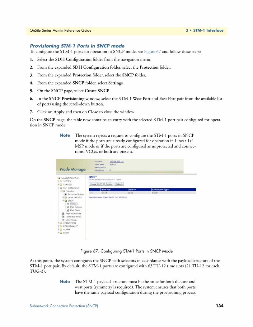
OnSite Series Admin Reference Guide 3 • STM-1 Interface
Provisioning STM-1 Ports in SNCP modeTo configure the STM-1 ports for operation in SNCP mode, see Figure 67 and follow these steps:
1. Select the SDH Configuration folder from the navigation menu.
2. From the expanded SDH Configuration folder, select the Protection folder.
3. From the expanded Protection folder, select the SNCP folder.
4. From the expanded SNCP folder, select Settings.
5. On the SNCP page, select Create SNCP.
6. In the SNCP Provisioning window, select the STM-1 West Port and East Port pair from the available list of ports using the scroll-down button.
7. Click on Apply and then on Close to close the window.
On the SNCP page, the table now contains an entry with the selected STM-1 port pair configured for opera-tion in SNCP mode.
Note The system rejects a request to configure the STM-1 ports in SNCP mode if the ports are already configured for operation in Linear 1+1 MSP mode or if the ports are configured as unprotected and connec-tions, VCGs, or both are present.
Figure 67. Configuring STM-1 Ports in SNCP Mode
At this point, the system configures the SNCP path selectors in accordance with the payload structure of the STM-1 port pair. By default, the STM-1 ports are configured with 63 TU-12 time slots (21 TU-12 for each TUG-3).
Note The STM-1 payload structure must be the same for both the east and west ports (symmetry is required). The system ensures that both ports have the same payload configuration during the provisioning process.
Subnetwork Connection Protection (SNCP) 134

OnSite Series Admin Reference Guide 3 • STM-1 Interface
Displaying and Configuring SNCP Path SettingsTo display and configure the path settings for individual SNCP path selectors, see Figure 75 and follow these steps:
1. Select the SDH Configuration folder from the navigation menu.
2. From the expanded SDH Configuration folder, select the Protection folder.
3. From the expanded Protection folder, select the SNCP folder.
4. From the expanded SNCP folder, select Path Settings.
Figure 68. Displaying and Configuring the SNCP Path Settings
At this point, the SNCP Path Settings page displays the current SNCP path settings for each TU-3 and TU-12 time slot on the STM-1 ports. Table 47 provides a list of the parameters for each SNCP path.
Note The system displays the table on the SNCP Path Settings page as empty when no ports are configured for operation in SNCP mode.
Table 47. SNCP Path Properties
Parameter Definition
West Path Location of VC-n path on the STM-1 west port.East Path Location of VC-n path on the STM-1 east port.TP Type Type of VC-n termination point: VC-3 or VC-12.SNCP SNCP protection indicator: enabled or disabled (disabled as default).Mode SNCP mode indicator: SNCP/I or SNCP/N.Primary Path Location of VC-n path from which the path selector normally drops traffic.Operation Type Path selector switch operation: revertive or non-revertive (nonrevertive as default).WTR Time Wait-to-restore time when path selector operates in revertive mode
(1 to 12 minutes, with 5 minutes as default).DEG Threshold Wait-to-restore time when path selector operates in revertive mode
(1 to 12 minutes, with 5 minutes as default).EXC Threshold Excessive error BER threshold when path selector operates in SNCP/N mode
(1e-3 to 1e-5, with 1e-3 as default).
Subnetwork Connection Protection (SNCP) 135

OnSite Series Admin Reference Guide 3 • STM-1 Interface
By default, SNCP protection is disabled for each TU-3 and TU-12 time slot. You can enable SNCP protection for any time slot directly on the SNCP Path Settings page, or you may choose to enable SNCP protection as you create individual connections.
Displaying and Configuring SNCP Path StatusTo display and configure the status of the SNCP path selector and the status of individual protected paths, see Figure 69 and follow these steps:
1. Select the SDH Configuration folder from the navigation menu.
2. From the expanded SDH Configuration folder, select the Protection folder.
3. From the expanded Protection folder, select the SNCP folder.
4. From the expanded SNCP folder, select Path Status.
Figure 69. Displaying and Configuring the SNCP Path Status
At this point, the SNCP Path Status page displays the current SNCP path status for each TU-3 and TU-12 time slot on the STM-1 ports. Table 48 on page 137 provides a list of the parameters for each SNCP path.
Hold Off Time Amount of time the path selector waits before switching from the primary to the secondary path in case of a failure in the primary path. The path selector switches to the secondary path only if the primary path is in the failed condition at the time the hold-off time expires. The timer is set in multiples of 100 msec, from 0 to 10 sec (0 sec as default).
Table 47. SNCP Path Properties
Parameter Definition
Subnetwork Connection Protection (SNCP) 136

OnSite Series Admin Reference Guide 3 • STM-1 Interface
Note The system displays the table on the SNCP Path Settings page as empty when no ports are configured for operation in SNCP mode.
Note The system displays N/A (Disabled) if SNCP protection is disabled for the time slot.
External Commands for SNCP Path SwitchingThe system allows the use of external commands to switch between east and west paths in SNCP configura-tion. Table 49 provides a list of the external commands that the system supports:
Table 48. SNCP Path Status
Parameter Indicates. . .
West Path Location of VC-n path on the west portEast Path Location of VC-n path on the east portSNCP Status Status of SNCP selector: normal, lockout, forced, manual, signal failure and signal degradeWest Status Status of VC-n path on the west port: active, standby, or failedEast Status Status of VC-n path on the east port: active, standby, or failedSwitched Channel Dropped channel selected by the path selector: east or west
Table 49. External Commands for SNCP Path Switching
Priority Command Action Completion
1 Clear Clears all switch commands Always2 Lockout Disables a switch to the protec-
tion pathAlways
3 Forced to Secondary Switches from the primary to the secondary path
Denied if the SF condition is present on the secondary path or if the Lockout com-mand is present
Forced to Primary Switches from the secondary to the primary path
Denied if the Lockout command is present
4 Manual to Secondary Switches from the primary to the secondary path
Denied if the SF or SD condition is present on the secondary path or if the Lockout or Forced command is present
Manual to Primary Switches from the secondary to the primary path
Denied if the SF or SD condition is present on the primary path or if the Lockout or Forced command is present
Subnetwork Connection Protection (SNCP) 137

OnSite Series Admin Reference Guide 3 • STM-1 Interface
To activate any of the external commands for SNCP path switching, see Figure 70 and follow these steps:
1. Select the SDH Configuration folder from the navigation menu.
2. From the expanded SDH Configuration folder, select the Protection folder.
3. From the expanded Protection folder, select the SNCP folder.
4. From the expanded SNCP folder, select Path Status.
5. On the SNCP Path Status page, select the table entry for the path for which you wish to activate the expernal commands and click on Status/Command.
Note The system supports the activation of the external commands only for paths in which SNCP protection is enabled.
6. In the SNCP Path Status & Switch Command window, use the scroll-down button to select one of the Command options in Table 49 on page 137. By default, Command is set to No Command.
7. Click on Initiate Command to activate the external command.
8. To reset any active command, select the Clear command option and click on Initiate Command. Other-wise, the current command remains active until a higher-priority command is issued or failure occurs (see Figure 70).
Figure 70. Configuring the External Commands for SNCP Path Switching
Subnetwork Connection Protection (SNCP) 138

OnSite Series Admin Reference Guide 3 • STM-1 Interface
Creating Cross-ConnectionsA cross-connection is a connection that supports time slot interchange (TSI) between any two STM-1 ports. This type of connection does not involve the mapping or demapping of client signal ports. As shown in Table 50, the OS-10 system supports two types of cross-connection: VC-3 and VC-12. Each cross-connection is characterized by three parameters: source, sink and direction. The STM-1 ports that contain the source and sink locations may be located in different slots in the system and need not use the same protection mode. For example, you may set up a VC-12 cross-connection between STM-1 base ports 1 and 2 in slot 1 operating in SNCP mode and STM-1 expansion ports 1 and 2 in slot 2 operating in Linear 1+1 MSP mode. You may also set up cross-connections between STM-1 ports in the same slot.
For cross-connections, the system does not require that you use the same time slot locations (U/K/L/M) for the source and sink points. All cross-connections are 2-way (or bidirectional) crossconnections by default. This means that the relationship between the source and sink points is the same for both directions of transmission. After the direction from source to sink is specified, the reverse direction is implicitly defined by the 2-way nature of the connection.
To create cross-connections at the VC-12 level, see Figure 71 on page 140 and follow these steps:
1. Select the CONNECTION folder from the navigation menu.
2. From the expanded CONNECTION folder, select Cross-Connections.
3. On the Cross-Connections page, click on Create Cross-Connection.
4. In the Create Cross-Connection window, set Level to VC-12.
5. Select the source STM-1 port using the STM-1 port (Source) scroll-down button.
The system displays only the first STM-1 port of a protected pair in a slot operating in SNCP or Linear 1+1 MSP mode. The scroll-down list includes both ports in a slot (STM-1 ports 1 and 2) if the ports operate in unprotected mode. The list also includes more than one STM-1 port if the system contains STM-1 expansion ports in slots 2 and 3.
The Protection Type indicates the protection mode for the selected port.
6. Select the TU-12 location or locations for the source using the TU-12 Location (Source) scrolldown but-ton.
7. Select the sink STM-1 port using the STM-1 port (Sink) scroll-down button.
8. Select the TU-12 location or locations for the sink using the TU-12 Location (Sink) scroll-down button.
To select more than one TU-12 location from the TU-12 Location... list, click on individual entries while pressing the Ctrl key. (The system highlights any entry that you select from the list. You can select any entry from the list, whether the TU-12 locations are contiguous or not.)
To select a range of consecutive entries from the list, select the first entry and then select the last entry while pressing the Shift key. Use the Reset button to restore the window to the default selection.
Table 50. Cross-Connection Types
Level Source Sink Direction
VC-3 TU-3 in STM-1 port 1 TU-3 in STM-1 port 2 2-wayVC-12 TU-12 in STM-1 port 1 TU-12 in STM-1 port 2 2-way
Subnetwork Connection Protection (SNCP) 139

OnSite Series Admin Reference Guide 3 • STM-1 Interface
Note Make sure that the number of selected entries from the TU-12 Loca-tion (Sink) list matches the number of selected TU-12s in the TU-12 Location (Source) before proceeding; otherwise, the system rejects the creation of the cross-connections.
9. Click on Apply to initiate the creation of the VC-12 cross-connections.
To create cross-connections at the VC-3 level, set Level to VC-3 in Step 4, and select the TU-3 location or locations for the source and sink points in the Create Cross-Connection window. The preceding notes and tips for TU-12 locations also apply to TU-3 locations.
Figure 71. Creating VC-12 Cross-Connections
The Create Cross-Connection window closes automatically after the system completes the creation of the VC-12 cross-con-nections. If the number of cross-connections is large, the system may take a few seconds to create the cross-connections and close the window. Closing the window manually before.the pro-cess is complete may cause an error or partial creation of the new cross-connections. Click on Refresh on the Cross-Connec-tions page to update the cross-connect table with the new con-nections after the window closes.
CAUTION
Subnetwork Connection Protection (SNCP) 140

OnSite Series Admin Reference Guide 3 • STM-1 Interface
Ring OperationsThis section provides options for the synchronization of OS-10 nodes in a ring topology and the procedures for adding and removing OS-10 nodes into and from a ring.
Ring SynchronizationThe OS-10 provides the following options for ring synchronization:
• Option 1: The head-end node of the ring is an OS-10 that uses external timing inputs at 2.048 MHz from a PRC-traceable source. All other nodes in the ring are OS-10 nodes set for STM-1 line timing. All nodes are set to process and generate synchronization status messaging (SSM).
• Option 2: The head-end node of the ring is an OS-10 node set in free-run mode using the internal Stratum 3 clock. All other nodes in the ring are OS-10 nodes set for STM-1 line timing. All nodes are set to process and generate SSM.
Option 2 may be used in applications where PRC-traceable source is not available at any site in the ring.
• Option 3: The head-end node of the ring is a third-party SDH node that uses timing from a PRCtraceable source. All other nodes in the ring are OS-10 nodes set for STM-1 line timing. All nodes in the ring are set to process and generate the SSM.
Adding and Deleting OS-10 NodesThe following section provides the procedures for the addition and deletion of OS-10 nodes into and from a ring.
Adding OS-10 Nodes into a RingTo add a new OS-10 node into a ring, follow these steps:
1. Install and power up the node that is being added into the ring.
2. Configure the system information, the Ethernet LAN management port, and system clock.
3. Configure the system for SNCP operation.
4. Configure the inband management channels for operation using the DCC.
Note Make sure that the DCC settings are compatible with the settings for the other nodes in the ring.
5. Set the system timing mode to Auto using the STM-1 ports as primary and secondary timing references.
Note This configuration is the same as STM-1 line timing.
6. Set up cross-connections for all TU-3 and TU-12 time slots that are being used in the ring.
Do not enable the STM-1 ports at this time. Wait until Step 11. Enabling the ports at this time may cause loss of traffic for exist-ing connections when the new node is connected to the adjacent nodes using the fiber optic cables (see Step 8 and Step 10).CAUTION
Ring Operations 141

OnSite Series Admin Reference Guide 3 • STM-1 Interface
7. Disconnect the fiber optic cables that connect the two nodes adjacent to the new node.
Note Fiber disconnection should occur at the site where the new node is being put into service. Make sure that the ends of the fiber have SC connectors before proceeding with Step 8. You may need to install the SC connectors if a fiber patch panel that uses this connector type is not present at the site.
At this point, the two adjacent nodes perform a protection switch to protect existing traffic in the ring.
8. Connect the ring fiber optic cables only to the receive side of the east and west STM-1 ports of the new node. Leave the transmit side of the ports disconnected.
Note Follow the procedure in “Subnetwork Connection Protection (SNCP)” on page 132 to connect the STM-1 ports of the new node to the STM-1 ports of the adjacent nodes. That is, port 1 (west) of one node should connect to port 2 (east) of another node.
Use the J0 trace to ensure that fiber connectivity is correct between adjacent nodes.
9. Check that the system timing status is “normal” and that sync quality level for either the primary or sec-ondary reference is other than DNU, or “do not use”.
At this point, the system should synchronize to one of the two incoming STM-1 signals. If the sync quality level for both references is DNU, the node is not properly synchronized to the other ring nodes.
Note Do not proceed until the sync quality level for at least one of the ref-erences is other than DNU.
10. Connect the ring fiber optic cables to the transmit side of the east and west STM-1 ports of the new node.
11. Enable STM-1 port 1 (west) and port 2 (east) at the same time.
The TU-3 and TU-12 cross-connections are required to support existing connections in the ring. If the cross-connections are not present at the moment the node goes into service in the ring, traf-fic loss occurs for existing connections.
At this point, any additional failure in ring may result in the loss of traffic for existing connections.
Make sure that the optical signal power level from the fiber that connects to the receive side of the port is within the limits in Table 33 for the interface type that is being used (S-1.1 or L-1.1) You may need to use an optical attenuator to prevent receiver over-load if the fiber span is short.
CAUTION
WARNING
CAUTION
Ring Operations 142

OnSite Series Admin Reference Guide 3 • STM-1 Interface
12. Confirm that the new node is reachable through the DCC channels and that existing traffic is not affected.
At this point, you may now set up connections between the client ports of the new node and other nodes in the ring.
Removing OS-10 Nodes from a RingTo remove an OS-10 node from a ring, follow these steps:
1. Remove all connections associated to the node that needs to be removed (or taken out of service).
Note This procedure includes connections between the node that is being removed and other nodes in the ring.
2. Power down the node and disconnect the node from its power source (AC or DC).
Note At this point, the two nodes adjacent to the node that is being removed perform a protection switch to protect the rest of the traffic in the ring.
3. Remove the fiber cables from STM-1 port 1 (west) and port 2 (east).
4. Patch through the fiber cables to restore fiber connectivity between the nodes adjacent to the node that is being removed.
Note The procedure does not disrupt remaining traffic in the ring for more than 50 msec.
Follow the safety precautions found in “Safety when using elec-tricity” on page 14 and the OnSite Series Getting Started Guide when working with AC or DC power connected to the system.
At this point, any additional failure in ring may result in the loss of traffic for existing connections.
Follow the safety precautions in “Optical Safety” on page 15 when working with fiber optic cables and laser devices.
CAUTION
WARNING
CAUTION
Ring Operations 143

OnSite Series Admin Reference Guide 3 • STM-1 Interface
Linear ADM (2-Fiber)To configure the OS-10 system for operation in 2-fiber (unprotected) Linear ADM mode, the two STM-1 ports on the base system must be configured as unprotected. In general, each unprotected STM-1 port may work independently from the other and can be configured with different payload structures (see “Configuring the SDH Payload Structure” on page 83). However, for proper operation of OS-10 nodes in a 2-fiber Linear ADM topology, it is important that you use the same payload structure for the east and west directions of transmission.
You can map and connect traffic from any E1/T1 client port to any available TU-12 time slot in either STM-1 port.
Note When the STM-1 ports operate in unprotected mode, the TU-12 Location list includes the available TU-12 time slots for both STM-1 port 1 and port 2. In contrast, the TU-12 Location list for the Linear 1+1 MSP mode includes only the available TU-12 locations for port 1 (because of the requirement for time slot symmetry in this mode).
You can also map and connect traffic from any Ethernet client port to any available VCAT group (VCG) in either STM-1 port. To create VCGs at VC-3 and VC-12 levels, see “Creating a VCG” on page 110.
Note When the STM-1 ports operate in unprotected mode, the Member Locations list includes the available TU-3 and TU-12 time slots for both STM-1 port 1 and port 2.
In general, VC-3 and VC-12 cross-connections do not require time slot symmetry between unprotected STM-1 ports. That is, the U/K/L/M index for the source and sink need not be the same. However, for proper opera-tion of OS-10 nodes in a 2-fiber Linear ADM topology, it is important that you use timeslot symmetry for all cross-connections.
Interconnection of OS-10 Nodes in a 2-Fiber Linear ADM TopologyAs shown in Figure 72 on page 145, a linear ADM chain of three OS-10 nodes must start from STM-1 port 1/2 (ST:1/2) at the Headend node. This port should be connected to STM-1 port 1/1 (ST:1/1) of the first Intermediate node and ST:1/2 of this node should be connected to ST:1/1 of the next node in the chain (the End node).
Note Both port ST:1/1 of the Headend node and port ST:1/2 of the End node are not used in this network and must be disabled.
In general, there can be more than one Intermediate node in a linear ADM. Therefore, all linear ADM chains must start with ST:1/2 at the Headend node and end with ST:1/1 at the End node, and all Intermediate notes must connect to each other using an alternating sequence of STM-1 ports 1 and 2.
When setting up fiber connections in a linear ADM chain, you must ensure that the west port of the ADM node (STM-1 port 1) connects to the east port (STM-1 port 2) of the adjacent ADM node. Continue the connection of ADM nodes in this manner until the linear topology is formed. This fiber connectivity is nec-essary to ensure proper operation of the linear network.
CAUTION
Linear ADM (2-Fiber) 144
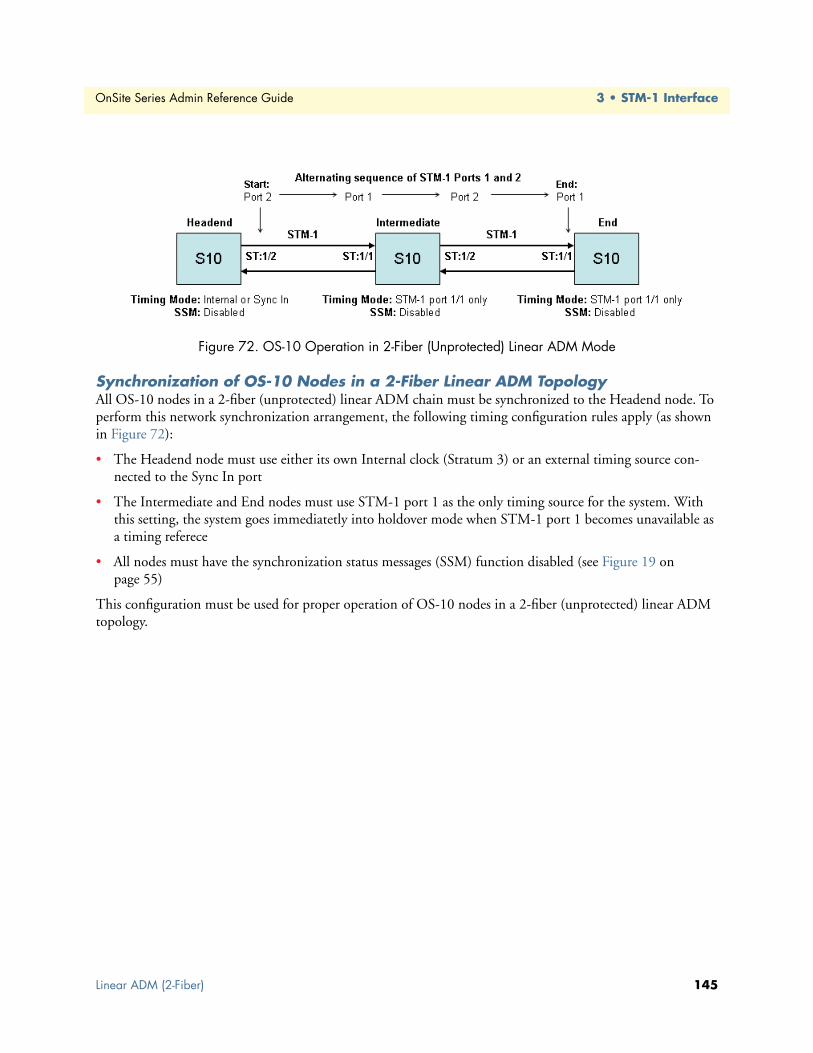
OnSite Series Admin Reference Guide 3 • STM-1 Interface
Figure 72. OS-10 Operation in 2-Fiber (Unprotected) Linear ADM Mode
Synchronization of OS-10 Nodes in a 2-Fiber Linear ADM TopologyAll OS-10 nodes in a 2-fiber (unprotected) linear ADM chain must be synchronized to the Headend node. To perform this network synchronization arrangement, the following timing configuration rules apply (as shown in Figure 72):
• The Headend node must use either its own Internal clock (Stratum 3) or an external timing source con-nected to the Sync In port
• The Intermediate and End nodes must use STM-1 port 1 as the only timing source for the system. With this setting, the system goes immediatetly into holdover mode when STM-1 port 1 becomes unavailable as a timing referece
• All nodes must have the synchronization status messages (SSM) function disabled (see Figure 19 on page 55)
This configuration must be used for proper operation of OS-10 nodes in a 2-fiber (unprotected) linear ADM topology.
Linear ADM (2-Fiber) 145

Chapter 4 E1/T1 Interface
Chapter contentsIntroduction ........................................................................................................................................................147General Information............................................................................................................................................147E1 and T1 Provisioning.......................................................................................................................................149
Enabling a Port for Service ............................................................................................................................149Disabling a Port from Service ........................................................................................................................151Configuring a Port for Synchronization ........................................................................................................151Retiming Mode .............................................................................................................................................153
E1 and T1 Connections ......................................................................................................................................153Creating a Port Connection ..........................................................................................................................153
Configuring the SNCP Protection Options for E1/T1 Connections .......................................................156Configuring the J2 Trace ........................................................................................................................158
Removing a Port Connection ........................................................................................................................159E1 and T1 Alarms ...............................................................................................................................................159
Monitoring Port Alarms ................................................................................................................................159Changing Port Alarm Default Severities ........................................................................................................161Displaying the Alarm Log .............................................................................................................................161
E1 and T1 Performance Monitoring ...................................................................................................................162Monitoring E1 and T1 Port Performance .....................................................................................................162Configuring E1 and T1 Port Threshold Crossing Alerts (TCA) ....................................................................164
E1 and T1 Testing...............................................................................................................................................166Configuring E1 and T1 Terminal Loopback .................................................................................................166Configuring E1 and T1 Facility Loopback ....................................................................................................166
146

OnSite Series Admin Reference Guide 4 • E1/T1 Interface
IntroductionThis chapter provides the procedures for provisioning, monitoring and testing of E1 and T1 client signal ports. Procedures for connecting E1 and T1 traffic to SDH are also provided.
General InformationThe OnSite OS-10 has 8 built-in E1 ports on the base OS1052 and 21 built-in E1 ports on the base OS1063 systems. E1 traffic is mapped into a VC-12 using asynchronous mapping, as specified in ITU-T Recommenda-tion G.707. The VC-12 is multiplexed into an STM-1 through the AU-4 multiplexing route, as shown in Figure 73.
As a factory-installed option, the OS-10 is also available with 8 built-in T1 ports on the base OS1052 and 21 built-in T1 ports on the base OS1063 systems. T1 traffic is mapped into VC-11 containers using asynchronous mapping, as specified in G.707. The system connects VC-11s carrying T1 traffic into TU-12 time slots, as shown in Figure 73.
Note Asynchronous mapping supports clear-channel transport of G.703 services at 2.048 Mbit/s ± 50 ppm for E1 signals and at 1.544 Mbit/s ± 32 ppm for T1 signals.
Figure 73. E1 and T1 Multiplexing over SDH
The E1 and T1 interfaces comply with the following standards:
• ITU-T G.703 (physical layer)
• ITU-T G.707 (SDH mapping)
• ITU-T G.775 (LOS detection)
• ITU-T G.826 (performance monitoring)
• ITU-T G.823 and G.783 (jitter and wander)
Introduction 147

OnSite Series Admin Reference Guide 4 • E1/T1 Interface
Figure 74 shows the location of the E1 and T1 ports on the base OS1052 and OS1063 systems.
Figure 74. E1 and T1 Ports on the Base OS1052 and OS1063 Systems
The OS1052 and OS1063 also allow the insertion of a 21-port E1 expansion module for applications that require access to additional E1 ports (see chapter 12 for details on the HD-E1 module); with two expansion modules, the OS1052 suports a total of 52 E1 ports. Figure 75 shows an OS1063 system equipped with two 21-port E1 modules for a total of 63 E1 ports.
Figure 75. OS1063 with two 21-port E1 Expansion Modules
Table 51 provides the interconnection parameters for the E1 and T1 port options for the base system.
Note The OS1052 and OS1063 support E1 signals with direct 120-ohm or 75-ohm termination as a factory-installed option.
Table 51. E1 and T1 Port Interconnection Parameters
Parameter E1 Ports T1 Ports
Connector Future Bus Future BusTermination 120-ohm (balanced) or 75-ohm (unbalanced) 100-ohm, balancedLine code HDB3 AMI or B8ZSInterconnecting cable Category 3 or 5 Category 3 or 5Reach Short-haul 655 feet
General Information 148

OnSite Series Admin Reference Guide 4 • E1/T1 Interface
The OS-10 uses a high-density Future Bus connector for access to the E1 ports. The connector is divided into six sections. Each section supports bidirectional transmission of four E1 ports. Connector section 6, however, supports only one E1 port for a combined total of 21 E1 ports.
E1 and T1 ProvisioningThe following section provides the procedures for enabling and disabling E1 and T1 ports. It also provides the procedures for configuring the external synchronization input and output ports, and the connection of traffic from E1 and T1 ports to SDH. The section concludes with the procedures for monitoring alarms and perfor-mance data at the E1 and T1 levels and setting up the loopback test function for E1 and T1 signals.
Enabling a Port for ServiceTo configure an E1 or a T1 port for service, see Figure 76 and Figure 77 on page 150 and follow these steps:
1. Select the CHASSIS folder from the navigation menu.
2. From the expanded CHASSIS folder, select Ports.
3. On the Ports page, select the E1 or T1 port being configured and click on Properties. The system displays all E1 or T1 ports in slot 1 of the base OS-10 system. It also displays all E1 ports in slot 2 and slot 3 if the system is equipped with E1 expansion modules.
Note The system uses the following naming convention for E1 and T1 interfaces: E1:slot/port and T1:slot/port. For instance, E1:1/3 refers to the E1 port 3 in slot 1. The base OS1052 system contains 8 E1 ports in slot 1 (the base system); that is, E1:1/1 through E1:1/8. The base OS1063 system contains 21 E1 ports in slot 1; that is, E1:1/1 through E1:1/21. If the system has a 21-port E1 expansion module in slot 2, E1:2/18 would refer to E1 port 18 in slot 2.
4. In the Port Properties window (see Figure 77 on page 150), set Admin Status to Enabled.
You can use the port selector filters at the top of the Ports page to narrow the selection of ports according to port type and location. By default, the filters are set to Show all port types in the Base board. To display, for instance, only the E1 ports in slot 2, use the scroll-down buttons to select Show E1/T1 ports and Slot 2. If you click on Enable All Ports, the system sets the Admin Status to Enabled for only the ports that are on display.
5. For systems that support the T1 port option, set the Line Coding to B8ZS (default) or AMI.
Note For E1 ports, the line coding is always set to HDB3.
6. For systems that support the T1 port option, use the Line Length (LBO meters) scroll-down button to select the line-build out (LBO) settings for the T1 port.
7. Click on Apply and then on Close to close the window.
On the Ports page, Admin Status for the selected E1 or T1 port should now read Enabled.
The E1 and T1 ports are non-telecommunications network voltage (TNV) and are for indoor use only. A CSU/DSU (channel service unit/data service unit) is required for outside plant installations.
WARNING
E1 and T1 Provisioning 149

OnSite Series Admin Reference Guide 4 • E1/T1 Interface
Figure 76. Displaying E1 and T1 Ports
Figure 77. Enabling an E1 or a T1 Port
Note The operational status (Oper Status) for an E1 or a T1 port is IS (in service) when the port Admin Status is Enabled and no alarms are present. Otherwise, the Oper Status for the port indicates OOS (out of service).
E1 and T1 Provisioning 150

OnSite Series Admin Reference Guide 4 • E1/T1 Interface
Disabling a Port from ServiceTo disable an E1 or a T1 port from service, follow these steps:
1. In the Port Properties window, set Admin Status to Disabled.
2. Click on Apply and then on Close to close the window.
On the Ports page, Admin Status for the selected E1 or T1 port should now read Disabled.
Note When an E1 or a T1 port is disabled, no port-related alarms are reported. PM data collection is also suspended. Furthermore, the sys-tem turns off the transmitter on the outgoing E1 or T1 signal. The system inserts E1 AIS into the VC-12 or T1 AIS into the VC-11 when an E1 or a T1 port is disabled, but remains connected to a TU-12 time slot.
Configuring a Port for SynchronizationThe Port Properties windows for E1 ports 7 and 8 in slot 1 of the OS1052 (that is, E1:1/7 and E1:1/8) are dif-ferent from other E1 ports in the base OS1052 system. Likewise, E1 ports 20 and 21 in slot 1 of the OS1063 (that is, E1:1/20 and E1:1/21) are different from other E1 ports in the base OS1063 system. These ports can be configured in one of three modes, as shown in Table 52.
To configure E1:1/7 and E1:1/8 in the OS1052 (or E1:1/20 and E1:1/21 in the OS1063) for synchronization purposes, see Figure 78 and follow these steps:
1. Select the CHASSIS folder from the navigation menu.
2. From the expanded CHASSIS folder, select Ports.
3. On the Ports page, select E1:1/7 in the OS1052 (or E1:1/20 in the OS1063) and click on Properties.
4. In the Port Properties window, set Port Signal Mode to one of the following: Sync In, Sync Out or Traf-fic.
Note By default, Port Signal Mode for E1:1/7 and E1:1/8 in the OS1052 (or E1:1/20 and E1:1/21 in the OS1063) is set to Traffic. In this mode, the system is synchronized using the derived clock from these ports when the timing mode is set to Auto: E1 port 7, port 8 in the OS1052 or Auto: E1 port 20, port 21 in the OS1063. The system allows the connection of E1 traffic between these ports and TU-12 time slots on the STM-1 port when the ports are set as Traffic.
Note The system does not allow the connection of E1 traffic between these ports and TU-12 time slots on the STM-1 port when the ports are set
Table 52. Configuration Modes for E1 Ports 7 and 8 (OS1052) and 20 and 21 (OS1063
Mode The Port . . .
Traffic Carries regular E1 traffic (default mode) and can be used for E1 line timingSync In Serves as an external timing input for synchronizing the OS-10 systemSync Out Serves as an external timing output for synchronizing other equipment
E1 and T1 Provisioning 151

OnSite Series Admin Reference Guide 4 • E1/T1 Interface
as Sync In or Sync Out. Conversely, if either port is already connected to a TU-12 time slot, the system does not allow setting the port as Sync In or Sync Out.
Note The OS1052 does not allow the configuration of E1 port 7 or port 8 to Sync Out if the system timing mode is set to Auto: E1 port 7, port 8. Likewise, the OS1063 does not allow the configuration of E1 port 20 or port 21 to Sync Out if the system timing mode is set to Auto: E1 port 20, port 2.
5. Click on Apply and then on Close to close the window.
On the Ports page, the Type field for E1:1/7 and E1:1/8 in the OS1052 (or E1:1/20 and E1:1/21 in the OS1063) reflects the current Port Signal Mode setting.
To configure the synchronization quality level of an E1 Sync In port, see Figure 78 and follow these steps:
1. In the Port Properties window for E1 port 7 and 8 in the OS1052 (or E1 port 20 and 21 in the OS1063), set the Sync Quality Level to one of the following options (PRC, SSU-A, SSU-B, SEC or DNU).
Note The default setting is DNU. The quality level should be set in accor-dance with the timing source that generates the E1 Sync In signals.
2. Click on Apply and then on Close to close the window.
Figure 78. Configuring the Sync In and Sync Out Options
E1 and T1 Provisioning 152

OnSite Series Admin Reference Guide 4 • E1/T1 Interface
Retiming ModeThe base OS1052 and OS1063 systems support a retiming function for E1 ports 1-8 in slot 1, individually. In the regular mode of operation, the system uses the recovered clock from the demapped E1 signal for transmis-sion into the physical E1 line. In the retiming mode, however, the system uses the system clock to transmit the E1 signal. You may use the retiming mode to distribute system timing to other equipment (such as PBXs or BTSs) that connects to the OS-10 at the E1 line level.
To enable the retiming feature for E1 ports in slot 1, see Figure 77 on page 150 and follow these steps:
1. Select the CHASSIS folder from the navigation menu.
2. From the expanded CHASSIS folder, select Ports.
3. On the Ports page, select E1:1/port and click on Properties.
Note The retiming function is available only for E1 port numbers 1-8, individually.
4. In the Port Properties window, set Retiming to Enabled.
5. Click on Apply and then on Close to close the window.
E1 and T1 ConnectionsThe following section describes the process of setting up and removing connections between E1 and T1 ports and SDH TU-12 time slots using asynchronous mapping into VC-12 and VC-11 termination points.
The system maps T1 signals into VC-11 containers and adds a fixed stuff column with even parity to transport the VC-11 within a selected TU-12 time slot. This process is called “VC-11 to VC-12 conversion for transport over a TU-12” and is specified in ITU-T G.707. The system identifies this VC-11 as a VC-12 termination point for connection and management purposes.
Creating a Port ConnectionTo connect an E1 or a T1 port to a TU-12, see Figure 79 on page 155and follow these steps:
1. Select the CONNECTION folder from the navigation menu.
2. From the expanded CONNECTION folder, select Client Port Mappings.
If no connections are present, the table on the Client Port Mappings page is empty.
3. On the Client Port Mappings page, use the Create Mapping Options... scroll-down button to select the Create E1/T1 Mapping option.
4. In the Create E1/T1 Mapping window, select the E1 or T1 port to be connected using the E1/T1 port scroll-down button.
The system allows the creation of several E1 and T1 port connections at a time. To select more than one E1 or T1 port from the E1/T1 port list, click on individual entries while pressing the Ctrl key. (The system high-lights any entry that you select from the list. You can select any entry from the list, whether the E1 or T1 ports are contiguous or not.)
To select a range of consecutive entries from the list, select the first entry and then select the last entry while pressing the Shift key.
E1 and T1 Connections 153

OnSite Series Admin Reference Guide 4 • E1/T1 Interface
Use the Reset button to restore the window to the default selection.
Note The scroll-down list displays only the E1 and T1 ports that remain unconnected to TU-12s. The system displays and allows the connec-tion of disabled E1 and T1 ports to TU-12s. An E1 or a T1 port con-nected to a TU-12 sends AIS over the VC-12 TP when the port is disabled.
You may enable (or disable) an E1 or a T1 port to activate (or deactivate) E1 or T1 service without deleting an existing connection. By connecting an E1 or a T1 port to a TU-12 and leaving the E1 or T1 port as disabled, you may test the connectivity and performance of the VC-12 path across the SDH network before allowing customer traffic from the E1 port to pass across the STM-1 interface.
5. Select the STM-1 port where you wish to connect the E1 or T1 port, using the STM-1 port scroll-down button.
The system presents a list of all available STM-1 ports in the system, including STM-1 ports in expansion slots 2 and 3, if present. The system also indicates the Protection Type for the selected port: Linear 1+1 MSP or SNCP.
6. Select the TU-12 to which the E1 or T1 port is to be connected using the TU-12 Location scrolldown button.
The scroll-down list system displays only the TU-12 time slots that remain unconnected in the selected STM-1 port.
Note The TU-12 Location for the TU-12 is indicated by the SDH index-ing scheme (ST:1/1-U/K/L/M. The system displays the default TU-12 Location associated with the selected E1 or T1 port. However, you can select any available TU-12 on the list.
Note By default, the system displays the TU-12 timeslots in logical sequence order. To display the timeslots in physical order, set TU Sequencing Type to Physical order.
To select more than one TU-12 location from the TU-12 Location list, click on individual entries while press-ing the Ctrl key. (The system highlights any entry that you select from the list. You can select any entry from the list, whether the TU-12 locations are contiguous or not.)
To select a range of consecutive entries from the list, select the first entry and then select the last entry while pressing the Shift key.
Use the Reset button to restore the window to the default selection.
Note Make sure that the number of selected entries from the list matches the number of selected E1 ports in the E1/T1 port list before pro-ceeding; otherwise, the system rejects the creation of the connections.
7. If you wish to connect the E1 or T1 port to the TU-12 as a 2-way (bidirectional) connection, leave Direc-tion as 2-way.
E1 and T1 Connections 154
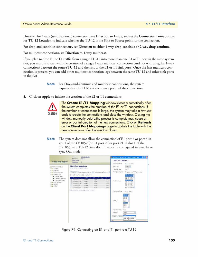
OnSite Series Admin Reference Guide 4 • E1/T1 Interface
However, for 1-way (unidirectional) connections, set Direction to 1-way, and set the Connection Point button for TU-12 Location to indicate whether the TU-12 is the Sink or Source point for the connection.
For drop-and continue connections, set Direction to either 1-way drop-continue or 2-way drop-continue.
For multicast connections, set Direction to 1-way multicast.
If you plan to drop E1 or T1 traffic from a single TU-12 into more than one E1 or T1 port in the same system slot, you must first start with the creation of a single 1-way multicast connection (and not with a regular 1-way connection) between the source TU-12 and the first of the E1 or T1 sink ports. Once the first multicast con-nection is present, you can add other multicast connection legs between the same TU-12 and other sink ports in the slot.
Note For Drop-and-continue and multicast connections, the system requires that the TU-12 is the source point of the connection.
8. Click on Apply to initiate the creation of the E1 or T1 connections.
Note The system does not allow the connection of E1 port 7 or port 8 in slot 1 of the OS1052 (or E1 port 20 or port 21 in slot 1 of the OS1063) to a TU-12 time slot if the port is configured in Sync In or Sync Out mode.
Figure 79. Connecting an E1 or a T1 port to a TU-12
The Create E1/T1 Mapping window closes automatically after the system completes the creation of the E1 or T1 connections. If the number of connections is large, the system may take a few sec-onds to create the connections and close the window. Closing the window manually before.the process is complete may cause an error or partial creation of the new connections. Click on Refresh on the Client Port Mappings page to update the table with the new connections after the window closes.
CAUTION
E1 and T1 Connections 155

OnSite Series Admin Reference Guide 4 • E1/T1 Interface
The Client Port Mappings table now displays the newly made connections (see Figure 80).
Note The system enables the VC-12 TP into which the E1 or T1 signal is mapped only after the connection is made. Only at this point the TU-12 time slot that carries the VC-12 TP no longer sends the unequipped signal.
Figure 80. Displaying E1 and T1 connections
Configuring the SNCP Protection Options for E1/T1 ConnectionsBy default, E1 or T1 connections to an SNCP-ready STM-1 port are unprotected. As shown in Figure 81, for unprotected connections, both directions of transmission are connected to STM-1 port 1 (west port) or port 2 (east port).
Figure 81. Unprotected E1 or T1 Connections
E1 and T1 Connections 156

OnSite Series Admin Reference Guide 4 • E1/T1 Interface
If an E1 or T1 port is connected to an STM-1 port that supports SNCP protection, you can protect the con-nection end point using SNCP/I or SNCP/N. When SNCP is enabled, the system activitates the bridging and path selector functions for the connection, as shown in Figure 66 on page 133.
To protect an existing E1 or T1 connection using SNCP, see Figure 80 on page 156 and Figure 82, and follow these steps:
1. On the Client Port Mappings page, select the table entry that contains the E1 or T1 connection that you wish to protect and click on Properties.
2. In the Connection Properties window, click on SNCP Path Properties.
3. In the SNCP Path Properties window, set SNCP to Enabled.
Note SNCP can be enabled only if the E1/T1 port is connected to STM-1 port 1 (west port).
At this time, you may change other SNCP path properties, including the Mode (SNCP/I or SNCP/N), Oper-ation Type (non-revertive or revertive) and Hold Off Time. If the Mode is set to SNCP/N, you may also change the DEG Threshold and EXC Threshold. (In SNCP/I mode, the system does not use the DEG and EXC thresholds to initiate the protection switch.) See Table 54 for the definitions of the SNCP path proper-ties. At this time you may also change the Primary Path from STM-1 port 1 (west port) to STM-1 port 2 (east port).
Note By default, the primary path in an SNCP connection is located on the west port. The primary and secondary paths are symmetrical. That is, both paths have the same TU-12 time slot index (U/K/L/M) on the east and west STM-1 ports.
4. Click on Apply and Close the SNCP Path Properties window.
5. Close the Connection Properties window.
Figure 82. Protecting E1 and T1 Connections Using SNCP
E1 and T1 Connections 157
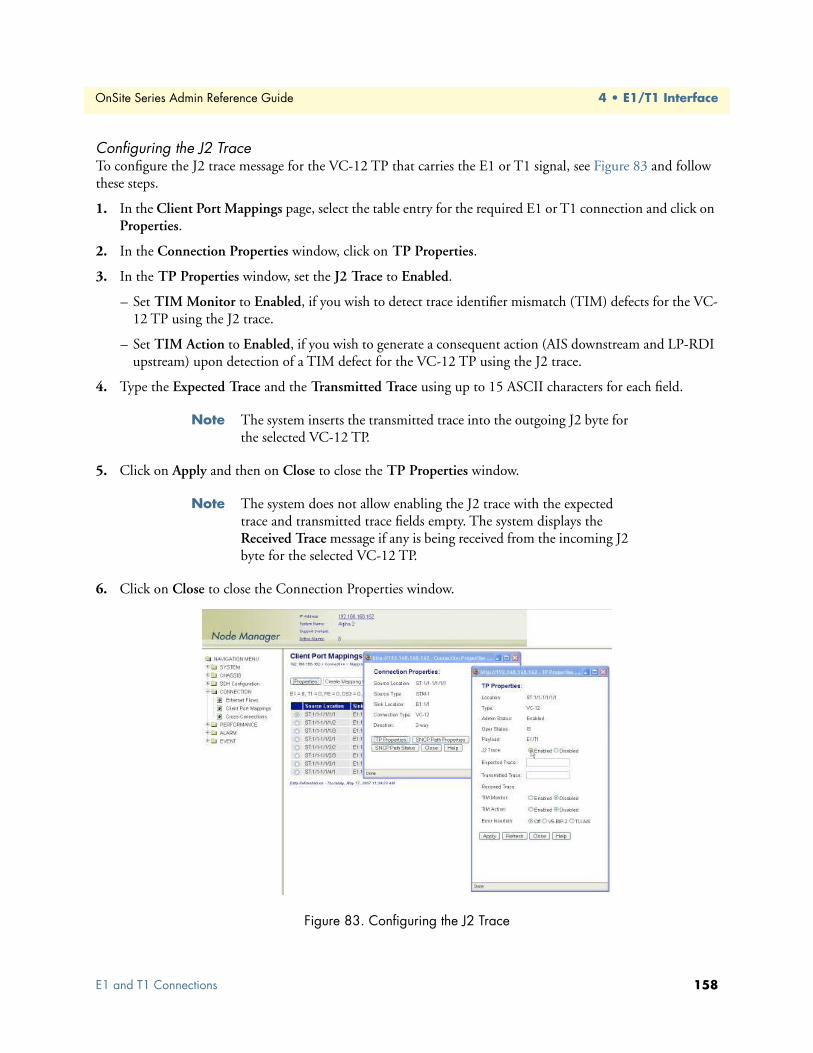
OnSite Series Admin Reference Guide 4 • E1/T1 Interface
Configuring the J2 TraceTo configure the J2 trace message for the VC-12 TP that carries the E1 or T1 signal, see Figure 83 and follow these steps.
1. In the Client Port Mappings page, select the table entry for the required E1 or T1 connection and click on Properties.
2. In the Connection Properties window, click on TP Properties.
3. In the TP Properties window, set the J2 Trace to Enabled.
– Set TIM Monitor to Enabled, if you wish to detect trace identifier mismatch (TIM) defects for the VC-12 TP using the J2 trace.
– Set TIM Action to Enabled, if you wish to generate a consequent action (AIS downstream and LP-RDI upstream) upon detection of a TIM defect for the VC-12 TP using the J2 trace.
4. Type the Expected Trace and the Transmitted Trace using up to 15 ASCII characters for each field.
Note The system inserts the transmitted trace into the outgoing J2 byte for the selected VC-12 TP.
5. Click on Apply and then on Close to close the TP Properties window.
Note The system does not allow enabling the J2 trace with the expected trace and transmitted trace fields empty. The system displays the Received Trace message if any is being received from the incoming J2 byte for the selected VC-12 TP.
6. Click on Close to close the Connection Properties window.
Figure 83. Configuring the J2 Trace
E1 and T1 Connections 158

OnSite Series Admin Reference Guide 4 • E1/T1 Interface
You can also configure the TP properties for all existing VC-12 TPs in the system by following these steps.
1. Select the SDH Configuration folder from the navigation menu.
2. From the expanded SDH Configuration folder, select Termination Points.
3. On the Termination Points page, select the table entry for the VC-12 TP that you wish to configure and click on Properties.
4. On the TP Properties window, you may know configure the J2 trace and the Error Insertion features for the selected VC-12 TP.
5. Click on Close to close the TP Properties window.
Removing a Port ConnectionTo remove an existing E1 or T1 port-to-TU-12 connection, follow these steps:
1. Select an E1 or a T1 port connection on the Client Port Mappings page.
2. Click on Delete to remove the port connection.
At this point, the system removes the connection and it is no longer displayed in the table.
Note The system automatically disables the VC-12 TP after deletion of the connection to the TU-12 time slot. At this point, the system starts to send the unequipped signal over this TU-12. The time slot is now available for other connections.
E1 and T1 AlarmsThe following section describes the process for monitoring alarms that may be present on E1 and T1 ports and the process of changing the default alarm settings.
Monitoring Port AlarmsTable 53 provides a list of the alarms that the system monitors at the E1 and T1 line level.
Note The system declares and displays an alarm condition if a defect per-sists for 2.5 ± 0.5 seconds. The alarm condition is cleared when the defect is terminated and remains absent for 10 ± 0.5 seconds.
The front panel provides an alarm status LED to indicate the presence of an active alarm condition of any severity level (Critical, Major, Minor, or Warning) on any of the eight E1 or eight T1 ports on the base OS-10 system. The LED is lit according to the color codes in Table 54 on page 160.
Table 53. E1 and T1 Line Alarms
Alarm Description Definition
PDH LOS Loss of Signal Incoming signal has no transitions for n consecutive pulse intervals
E1 and T1 Alarms 159

OnSite Series Admin Reference Guide 4 • E1/T1 Interface
To display E1 and T1 alarms, if present, see Figure 84 and follow these steps:
1. Select the ALARM folder from the navigation menu.
2. From the expanded ALARM folder, select Show Active Alarms.
At this point, the Active Alarms page displays all active alarms in the system, including E1 and T1 alarms, if present. The table contains a separate entry for each active alarm. Table 55 describes the fields for each E1 and T1 alarm entry.
Note The system automatically updates the Active Alarms page every 60 seconds. Click on Refresh if you need to update the table with the most recent active alarm information. Individual table entries auto-matically clear whenever previously active alarms are no longer present.
Figure 84. Displaying E1 and T1 Port Alarms
Table 54. E1 or T1 Alarm Status LED
LED Color Description
Green No alarm is present on any port.Amber An alarm is present on one or more ports.
Off All E1 or T1 ports are disabled.
Table 55. Table Entries for Active E1 and T1 Alarms
Table Entry for Active Alarms Field Value
Type PDH LOS, LoopbackAlarm Raised Time Date and time
Severity Critical, Major, Minor, or WarningDetailed Information Location of affected E1 or T1 port (E1:slot/port or T1:slot/port)
E1 and T1 Alarms 160

OnSite Series Admin Reference Guide 4 • E1/T1 Interface
Changing Port Alarm Default SeveritiesTable 56 provides the default severities for E1 and T1 line alarms:
To change the default severity for supported E1 and T1 alarms, follow these steps:
1. Select the ALARM folder from the navigation menu.
2. From the expanded ALARM folder, select Set Alarm Severity.
At this point, the Alarm Severity page displays a table with all supported system alarms.
3. Select the table entry containing the E1 or T1 port alarm Type (PDH LOS) and click on Change.
4. In the Alarm Severity window, set Severity to any desired level (Critical, Major, Minor, or Warning).
5. Click on Apply and then on Close to close the window.
On the Alarm Severity page, the Severity for the selected E1 or T1 port alarm Type should now reflect the change in the reported severity level.
Note The change applies to all E1 and T1 ports within the system.
Displaying the Alarm LogTo display historical alarms, including any E1 or T1 port alarms if present, follow these steps:
1. Select the ALARM folder from the navigation menu.
2. From the expanded ALARM folder, select Show Alarm Log.
At this point, the Alarm Log page displays a list of the 50 most recent alarm messages. The system keeps up to 500 entries in the alarm log.
Note The alarm log is a FIFO (first-in fist-out) log.
Click on Last 50 Log Entries or Next 50 Log Entries to move around and display the entire contents of the log. Click on Clear Log if you wish to delete permanently the current log entries.
Table 56. E1 and T1 Line Alarm Default Severities
Monitored Entity Near-end Alarm Default Severity
E1 or T1 port PDH LOS Critical
E1 and T1 Alarms 161

OnSite Series Admin Reference Guide 4 • E1/T1 Interface
E1 and T1 Performance MonitoringThe following section describes the process for displaying current and historical PM data for E1 and T1 ports.
Monitoring E1 and T1 Port PerformanceTable 57 provides a list of the E1 and T1 Line PM parameters (near-end) that the system monitors in accor-dance with G.826.
To display current PM data for an E1 or a T1 port, see Figure 85 on page 163 and follow these steps:
1. Select the CHASSIS folder from the navigation menu.
2. From the expanded CHASSIS folder, select Ports.
3. On the Ports page, select the E1 or T1 port being configured and click on Show PM.
At this point, the E1/T1 Near-end PM page shows the near-end PM data for both the current 15-minute and 24-hour periods.
Note The PM data is not updated automatically as new events occur dur-ing the current 15-minute and 24-hour periods. Click on Refresh to update the tables with the most recent cumulative count for the cur-rent periods.
Continue with the steps that follow to display historical PM data.
4. Click on Show Interval.
At this point, the E1/T1 Near-end PM page shows the near-end PM data for the following intervals:
• Current plus previous 95-by-15-minute intervals (24 hours total)
• Current plus previous day (2 days total)
Click on Refresh to update the tables with the most recent cumulative count for the current periods. This action updates only the first entry in the tables, which corresponds to the current measurement period.
Table 57. E1 and T1 Line PM Parameters
Parameter Description Definition
LCV Line Coding Violation Count of BPV or EXZ over the accumulation periodES Errored Second Count of seconds in which the LCV count is greater than
or equal to 1 or in which a LOS defect occursSES Severely Errored Second Count of seconds in which the LCV count is greater than
or equal to 2048 for E1 signals (1544 for T1 signals) or in which a LOS defect occurs
UAS Unavailable Seconds Period of unavailable time that begins at the onset of 10 consecutive SES
E1 and T1 Performance Monitoring 162

OnSite Series Admin Reference Guide 4 • E1/T1 Interface
Note The tables display Invalid under PM data when the data collected during a measurement period is considered invalid. The Interval Start Time also displays n/a (not available).
Figure 85. Displaying Current PM Data for E1 and T1 Ports
To display current and historical PM data for all E1 and T1 ports in the system, see Figure 86 on page 164 and follow these steps:
1. Select the PERFORMANCE folder from the navigation menu.
2. From the expanded PERFORMANCE folder, select Counters.
3. From the expanded Counters folder, select E1/T1.
At this point, the E1/T1 Near-end PM page shows the near-end PM data for the current 15-minute period only. The table displays PM data for only enabled E1/T1 ports. (The table entries are empty if no E1/T1 ports are enabled.)
Continue with the steps that follow to display historical PM data for both 15-minute and 24-hour periods.
4. Select an E1 or a T1 port and click on Show Interval.
Note The preceding notes for the E1/T1 Near-end PM page also apply to this procedure.
E1 and T1 Performance Monitoring 163

OnSite Series Admin Reference Guide 4 • E1/T1 Interface
Figure 86. Displaying Current PM Data for All E1 and T1 Ports
To clear the current PM data for an E1 or a T1 port, see Figure 86 and follow this step:
1. On the E1/T1 Near-end PM page, select an E1 or a T1 port entry and use the Clear Counter Options... scroll-down button to select one of the available options for clearing the current 15-minute counter, 24-hour counter, or both.
Configuring E1 and T1 Port Threshold Crossing Alerts (TCA)The system supports threshold registers for E1 and T1 port PM parameters. A TCA event is generated when a monitored event reaches or crosses the preset threshold value within a given measurement period (15 minutes or 24 hours).
To configure the system for reporting TCA events at the E1 or T1 port level, follow these steps:
Note By default, the reporting of TCA events for E1 and T1 ports is dis-abled.
1. Select the EVENT folder from the navigation menu.
2. From the expanded EVENT folder, select Enable TCA Event.
3. On the TCA Event Disable / Enable page, change TCA Events (E1/T1) to On.
4. Click on Apply to complete this task.
Note This is a global setting. Enabling the report of TCA events applies to all E1 and T1 ports on the system.
E1 and T1 Performance Monitoring 164

OnSite Series Admin Reference Guide 4 • E1/T1 Interface
To configure the default TCA settings for E1 and T1 ports, follow these steps:
1. Select the PERFORMANCE folder from the navigation menu.
2. From the expanded PERFORMANCE folder, select the TCA Settings folder.
3. From the expanded TCA Settings folder, select the E1/T1 folder.
4. From the expanded E1/T1 folder, select Default.
5. On the E1/T1 Default TCA Settings page, select the table entry and click on Change.
6. In the E1/T1 Default TCA Settings window, change the default TCA settings for the E1 and T1 line ES, SES, UAS and LCV parameters (current and day periods) as required.
Note The system displays the factory default TCA settings when you first open this page. Afterwards, the system displays any recent configura-tion changes. The preferred method of restoring the original settings is to reenter the values manually.
7. Click on Apply and then on Close to close the E1/T1 Default TCA Settings window.
Note The default values apply to all E1 and T1 ports on the system.
To assign custom TCA values for each individual E1 or T1 port on the system, continue with Step 8; other-wise, Step 7 completes this task.
8. From the expanded E1/T1 folder, select Custom.
At this point, the E1/T1 TCA Settings page displays the current TCA settings for each E1 and T1 port on the system. The table entry indicates Default if the default TCA value is in use for a given parameter or Custom (value) if the system uses any custom value other than the default.
9. On the E1/T1 TCA Settings page, select the E1 or T1 port that you wish to configure and click on Change.
10. In the E1/T1 TCA Settings window, select Custom for the TCA settings that you wish to customize and change the setting to any value within the allowable range.
Note You may change the TCA settings for more than one parameter at a time.
11. Click on Apply and then on Close to close the E1/T1 TCA Settings window.
At this point, the E1/T1 TCA Settings page reflects any recent configuration changes.
If you wish to change a TCA setting back to its default setting, select Default instead of Custom in Step 10.
E1 and T1 Performance Monitoring 165

OnSite Series Admin Reference Guide 4 • E1/T1 Interface
E1 and T1 TestingThe following section provides the procedures for enabling and disabling loopback tests for E1 and T1 ports.
Configuring E1 and T1 Terminal LoopbackThe OS-10 system supports terminal loopback for E1 and T1 ports. As shown in Figure 87, while the terminal loopback is active, the E1 or T1 signal is looped back towards the STM-1 interface just before transmission on the E1 or T1 physical interface. E1 or T1 AIS is also transmitted on the physical port. Terminal loopback allows the testing of the performance and connectivity for an E1 or a T1 service across the SDH network.
Figure 87. E1 and T1 Terminal Loopback
Configuring E1 and T1 Facility LoopbackThe OS-10 system supports facility loopback for E1 and T1 ports, as shown in Figure 88. The loopback point occurs before mapping the E1 signal into a VC-12 or T1 signal into a VC-11. If a connection is already present, the system inserts E1 AIS into the VC-12 payload container (C-12) or T1 AIS into the VC-11 payload container (C-11) while the facility loopback is active. Facility loopback allows the testing of the performance and connectivity of the E1 or T1 cabling between the OS-10 system and the end-user equipment.
Figure 88. E1 and T1 Facility Loopback
E1 and T1 Testing 166

OnSite Series Admin Reference Guide 4 • E1/T1 Interface
To start an E1 or a T1 terminal loopback (or facility loopback) test, see Figure 89 and follow these steps:
1. Select the CHASSIS folder from the navigation menu.
2. From the expanded CHASSIS folder, select Ports.
3. On the Ports page, select the E1 or T1 port being tested and click on Properties.
4. In the Port Properties window, click on Start Terminal Loopback or Start Facility Loopback.
A warning window opens to alert you to the start of the loopback test. Click on OK to continue or Cancel to cancel the request.
Loopback Status on the Port Properties window changes to Terminal Loopback Active or Facility Loopback Active. Admin Status for the port changes to Testing.
5. Click on Close to close the Port Properties window.
Figure 89. Activating E1 Loopback
To stop an E1 or a T1 loopback test, follow these steps:
1. In the Port Properties window, set Admin Status to Enabled or Disabled, if required.
2. Click on Apply.
At this point, Loopback Status changes to No Loopback. The system resumes any connection previously present between the E1 or T1 port and a TU-12 time slot.
3. Click on Close to close the the Port Properties window.
Starting an E1 or a T1 terminal loopback causes traffic disruption if the E1 or T1 port is already connected to a TU-12.
WARNING
E1 and T1 Testing 167

Chapter 5 DS3/E3 Interface
Chapter contentsIntroduction ........................................................................................................................................................169General Information............................................................................................................................................169DS3 and E3 Provisioning ....................................................................................................................................171
Enabling a Port for Service ............................................................................................................................171Disabling a Port from Service ........................................................................................................................173
DS3/E3 Connections ..........................................................................................................................................173Creating a Port Connection ..........................................................................................................................173
Configuring the SNCP Protection Options for DS3/E3 Connections .....................................................176Configuring the J1 Trace ........................................................................................................................177
Removing a Port Connection ........................................................................................................................178DS3/E3 Alarms ...................................................................................................................................................178
Monitoring Port Alarms ................................................................................................................................178Changing Port Alarm Default Severities ........................................................................................................180Displaying the Alarm Log .............................................................................................................................180
DS3/E3 Performance Monitoring .......................................................................................................................181Monitoring DS3/E3 Line Performance .........................................................................................................181Monitoring DS3/E3 Path Performance .........................................................................................................183Configuring DS3/E3 Port Threshold Crossing Alerts (TCA) ........................................................................184
TCA Settings for DS3/E3 Ports at the Line Level ....................................................................................184TCA Settings for DS3/E3 Ports at the Path Level ...................................................................................186
DS3/E3 Testing...................................................................................................................................................186Configuring DS3/E3 Terminal Loopback .....................................................................................................186Configuring DS3/E3 Facility Loopback ........................................................................................................187
168

OnSite Series Admin Reference Guide 5 • DS3/E3 Interface
IntroductionThis chapter provides the procedures for provisioning, monitoring, and testing of DS3 and E3 client signal ports using the 3-port DS3/E3 expansion module. Procedures for connecting DS3 and E3 traffic to SDH are also provided.
General InformationThe DS3/E3 module has three (3) built-in DS3/E3 interface ports.
DS3/E3 traffic is mapped into a VC-3 using asynchronous mapping, as specified in ITU-T Recommendation G.707. The VC-3 is multiplexed into an STM-1 through the AU-4 multiplexing route, as shown in Figure 90.
Note Asynchronous mapping supports clear-channel transport of G.703 services at 44.736 Mbit/s ± 20 ppm for DS3 signals and at 34.368 Mbit/s ± 20 ppm for E3 signals.
Figure 90. DS3 and E3 Multiplexing over SDH
The DS3 and E3 interfaces comply with the following standards:
• ITU-T G.703 and GR-449 (physical layer)
• ITU-T G.707 (SDH mapping)
• ITU-T G.775 and GR-499 (LOS detection)
• ITU-T G.826 and ANSI T1.231 (performance monitoring)
• ITU-T G.823, G.783, and GR-253 (jitter and wander)
For each DS3/E3 port, the module supports non-intrusive monitoring of path-level defects and the collection of performance-monitoring data in both directions of transmission (receive and transmit sides).
For ports configured as DS3, the system supports the following framing formats:
• M23
• C-bit parity
• Unframed
Introduction 169

OnSite Series Admin Reference Guide 5 • DS3/E3 Interface
For ports configured as E3, the system supports the following framing formats:
• G.751
• G.832
• Unframed
The activation of the line framer does not disrupt or change the bit stream of the signal, even if the framer detects an incoming signal failure. (For example, the framer, if enabled, does not generate an AIS signal down-stream upon detection of a loss-of-frame condition on the DS3 or E3 signal).
Figure 91 shows the location of the DS3 and E3 ports on the module.
Figure 91. DS3 and E3 Ports on the 3-Port DS3/E3 Module
Table 58 provides the interconnection parameters for the DS3 and E3 port options.
Table 58. DS3 and E3 Port Interconnection Parameters
Parameter DS3 Ports E3 Ports
Connector DIN 1.0/2.3 DIN 1.0/2.3Termination 75-ohm, unbalanced 75-ohm, unbalancedLine code B3ZS HDB3
Interconnecting cable Coaxial cable Coaxial cableReach 450 feet to DSX panel or 900 feet from
transmit to receive450 feet to DSX panel or 900 feet from
transmit to receive
General Information 170

OnSite Series Admin Reference Guide 5 • DS3/E3 Interface
DS3 and E3 ProvisioningThe following section provides the procedures for enabling and disabling DS3 and E3 ports. The section con-cludes with the procedures for monitoring alarms and performance data at the DS3 and E3 levels and setting up the loopback test function for DS3 and E3 signals.
Enabling a Port for ServiceTo configure a DS3/E3 port for service, see Figure 92 and Figure 93 on page 172 and follow these steps:
1. Select the CHASSIS folder from the navigation menu.
2. From the expanded CHASSIS folder, select Ports.
3. On the Ports page, select the DS3 or E3 port being configured and click on Properties.
Note The system displays all DS3/E3 ports in slots 2 and 3 if the system is equipped with DS3/E3 expansion modules in those slots.
Note The system uses the following naming convention for DS3/E3 inter-faces: T3:slot/port. For instance, T3:2/3 refers to the third DS3/E3 port in slot 2.
4. In the Port Properties window (see Figure 93), set Admin Status to Enabled.
You can use the port selector filters at the top of the Ports page to narrow the selection of ports according to port type and location. To display, for instance, only the DS3/E3 ports in slot 3, use the scroll-down buttons to select Show DS3/E3 ports and Slot 3. If you click on Enable All Ports, the system sets the Admin Status to Enabled for only the ports that are on display.
5. Set the Line Rate to DS3 (default) or E3.
For DS3 ports, the line coding is set to B3ZS. For E3 ports, the line coding is set to HDB3. The system dis-plays the correct line coding for the port after you click on Apply in Step 8.
6. Select the Line Framing for the DS3/E3 port.
Use the line framing setting if you wish to enable non-intrusive monitoring of DS3/E3 path-level defects and the collection of performance-monitoring data in both directions of transmission, that is, from the physical DS3/E3 port into the VC-3 (receive direction) and from the VC-3 into the physical port (transmit direction).
Make sure that the line framing setting corresponds to the actual frame structure of the DS3/E3 signal that is being monitored. For DS3 signals using C-bit parity framing, set the Line Framing to C-bit Parity to start the the collection of DS3 path PM data using both the P-bits and the CP-bits. For DS3 signals using M23 fram-ing, set the Line Framing to M23; otherwise, setting the Line Framing to C-bit Parity results in the incorrect collection of PM data using the CP-bits.
Note The system starts the collection of DS3/E3 path-monitoring data when the port is enabled and the framer is set to the correct signal frame structure.
7. Use the Line Length (LBO meters) scroll-down button to select the line-build out (LBO) settings for the DS3 port.
DS3 and E3 Provisioning 171
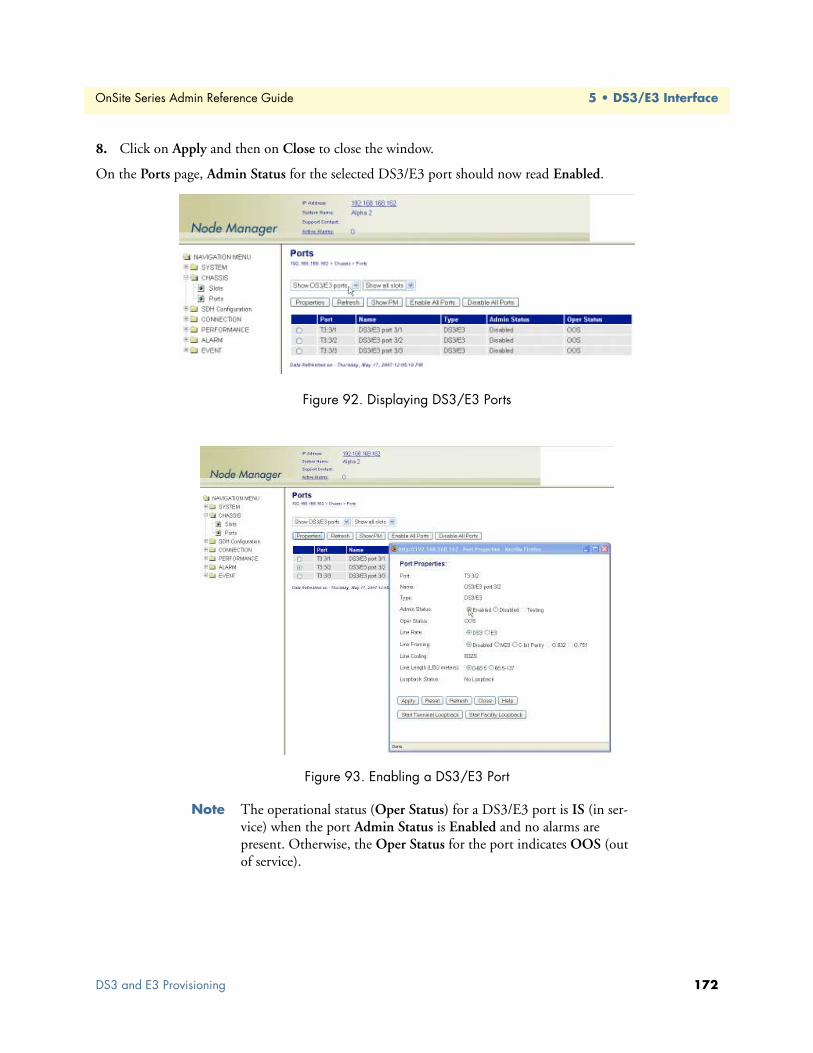
OnSite Series Admin Reference Guide 5 • DS3/E3 Interface
8. Click on Apply and then on Close to close the window.
On the Ports page, Admin Status for the selected DS3/E3 port should now read Enabled.
Figure 92. Displaying DS3/E3 Ports
Figure 93. Enabling a DS3/E3 Port
Note The operational status (Oper Status) for a DS3/E3 port is IS (in ser-vice) when the port Admin Status is Enabled and no alarms are present. Otherwise, the Oper Status for the port indicates OOS (out of service).
DS3 and E3 Provisioning 172

OnSite Series Admin Reference Guide 5 • DS3/E3 Interface
Disabling a Port from ServiceTo disable a DS3/E3 port from service, follow these steps:
1. In the Port Properties window, set Admin Status to Disabled.
2. Click on Apply and then on Close to close the window.
On the Ports page, Admin Status for the selected DS3/E3 port should now read Disabled.
Note When a DS3/E3 port is disabled, no port-related alarms are reported. PM data collection is also suspended. Furthermore, the system turns off the transmitter on the outgoing DS3/E3 signal.
Note The system inserts AIS into the VC-3 when a DS3/E3 port is dis-abled but remains connected to a TU-3 time slot.
DS3/E3 ConnectionsThe following section describes the process of setting up and removing connections between DS3/E3 ports and SDH TU-3 time slots using asynchronous mapping into VC-3 termination points.
Creating a Port ConnectionTo connect a DS3/E3 port to a TU-3, see Figure 94 on page 175 and follow these steps:
1. Select the CONNECTION folder from the navigation menu.
2. From the expanded CONNECTION folder, select Client Port Mappings.
If no connections are present, the table on the Client Port Mappings page is empty.
3. On the Client Port Mappings page, use the Create Mapping Options... scroll-down button to select the Create DS3/E3 Mapping option.
4. In the Create DS3/E3 Mapping window, select the DS3/E3 port to be connected using the DS3/E3 port scroll-down button.
The system allows the creation of several DS3/E3 port connections at a time. To select more than one DS3/E3 port from the DS3/E3 port list, click on individual entries while pressing the Ctrl key. (The system highlights any entry that you select from the list. You can select any entry from the list, whether the E1 or T1 ports are contiguous or not.)
To select a range of consecutive entries from the list, select the first entry and then select the last entry while pressing the Shift key.
Use the Reset button to restore the window to the default selection.
Note The scroll-down list displays only the DS3/E3 ports that remain unconnected to TU-3s. The system displays and allows the connec-tion of disabled DS3/E3 ports to TU-3s. A DS3/E3 port connected to a TU-3 sends AIS over the VC-3 TP when the port is disabled.
You may enable (or disable) a DS3/E3 port to activate (or deactivate) DS3/E3 service without deleting an existing connection. By connecting a DS3/E3 port to a TU-3 and leaving the port as disabled, you may test the
DS3/E3 Connections 173

OnSite Series Admin Reference Guide 5 • DS3/E3 Interface
connectivity and performance of the VC-3 path across the SDH network before allowing customer traffic from the port to pass across the STM-1 interface.
5. Select the TU-3 to which the port is to be connected using the TU-3 Location scroll-down button.
To select more than one TU-3 location from the TU-3 Location list, click on individual entries while pressing the Ctrl key. (The system highlights any entry that you select from the list. You can select any entry from the list, whether the TU-3 locations are contiguous or not.)
To select a range of consecutive entries from the list, select the first entry and then select thelast entry while pressing the Shift key.
Use the Reset button to restore the window to the default selection.
Note Make sure that the number of selected entries from the list matches the number of selected DS3/E3 ports in the DS3/E3 port list before proceeding; otherwise, the system rejects the creation of the connec-tions.
Note The TU-3 Location for the TU-3 is indicated by the SDH indexing scheme (ST:1/1-U/K/L/M). The system displays the default TU-3 Location associated with the selected port. However, you can select any available TU-3 on the list.
The scroll-down list displays only the TU-3 time slots that remain unconnected.
6. If you wish to connect the DS3/E3 port to the TU-3 as a 2-way (bidirectional) connection, leave Direc-tion as 2-way.
However, for 1-way (unidirectional) connections, set Direction to 1-way, and set the Connection Point button for TU-3 Location to indicate whether the TU-3 is the Sink or Source point for the connection.
For drop-and continue connections, set Direction to either 1-way drop-continue or 2-way drop-continue.
For multicast connections, set Direction to 1-way multicast.
If you plan to drop DS3/E3 traffic from a single TU-3 into more than one DS3/E3 port in the same system slot, you must first start with the creation of a single 1-way multicast connection (and not with a regular 1-way connection) between the source TU-3 and the first of the DS3/E3 sink ports. Once the first multicast connec-tion is present, you can add other multicast connection legs between the same TU-3 and other sink ports in the slot.
Note For Drop-and-continue and multicast connections, the system requires that the TU-3 is the source point of the connection.
7. Click on Apply to initiate the creation of the DS3/E3 connections.
DS3/E3 Connections 174

OnSite Series Admin Reference Guide 5 • DS3/E3 Interface
Figure 94. Connecting a DS3/E3 Port to a TU-3
The Client Port Mappings table now displays the newly made connections (see Figure 95).
Note The system enables the VC-3 TP into which the DS3/E3 signal is mapped only after the connection is made. Only at this point the TU-3 time slot that carries the VC-3 TP no longer sends the unequipped signal.
Figure 95. Displaying DS3/E3 Connections
The Create DS3/E3 Mapping window closes automatically after the system completes the creation of the DS3/E3 connec-tions. If the number of connections is large, the system may take a few seconds to create the connections and close the window. Closing the window manually before.the process is complete may cause an error or partial creation of the new connections. Click on Refresh on the Client Port Mappings page to update the table with the new connections after the window closes.
CAUTION
DS3/E3 Connections 175

OnSite Series Admin Reference Guide 5 • DS3/E3 Interface
Configuring the SNCP Protection Options for DS3/E3 ConnectionsIf a DS3/E3 port is connected to an STM-1 port that supports SNCP protection, you can protect the connec-tion end point using SNCP/I or SNCP/N.
To protect an existing DS3/E3 connection using SNCP, see Figure 96, and follow these steps:
1. On the Client Port Mappings page, select the table entry that contains the DS3/E3 connection that you wish to protect and click on Properties.
2. In the Connection Properties window, click on SNCP Path Properties.
3. In the SNCP Path Properties window, set SNCP to Enabled.
Note SNCP can be enabled only if the DS3/E3 port is connected to STM-1 port 1 (west port).
At this time, you may change other SNCP path properties, including the Mode (SNCP/I or SNCP/N), Oper-ation Type (non-revertive or revertive) and Hold Off Time. If the Mode is set to SNCP/N, you you may also change the DEG Threshold and EXC Threshold. (In SNCP/I mode, the system does not use the DEG and EXC thresholds to initiate the protection switch.)
At this time you may also change the Primary Path from STM-1 port 1 (west port) to STM-1 port 2 (east port).
Note By default, the primary path in an SNCP connection is located on the west port. The primary and secondary paths are symmetrical. That is, both paths have the same TU-3 time slot index (U/K/L/M) on the east and west STM-1 ports.
4. Click on Apply and Close the SNCP Path Properties window.
5. Close the Connection Properties window.
Figure 96. Protecting DS3/E3 Connections Using SNCP
DS3/E3 Connections 176
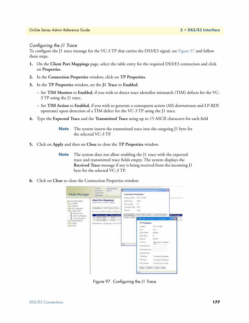
OnSite Series Admin Reference Guide 5 • DS3/E3 Interface
Configuring the J1 TraceTo configure the J1 trace message for the VC-3 TP that carries the DS3/E3 signal, see Figure 97 and follow these steps.
1. On the Client Port Mappings page, select the table entry for the required DS3/E3 connection and click on Properties.
2. In the Connection Properties window, click on TP Properties.
3. In the TP Properties window, set the J1 Trace to Enabled.
– Set TIM Monitor to Enabled, if you wish to detect trace identifier mismatch (TIM) defects for the VC-3 TP using the J1 trace.
– Set TIM Action to Enabled, if you wish to generate a consequent action (AIS downstream and LP-RDI upstream) upon detection of a TIM defect for the VC-3 TP using the J1 trace.
4. Type the Expected Trace and the Transmitted Trace using up to 15 ASCII characters for each field
Note The system inserts the transmitted trace into the outgoing J1 byte for the selected VC-3 TP.
5. Click on Apply and then on Close to close the TP Properties window.
Note The system does not allow enabling the J1 trace with the expected trace and transmitted trace fields empty. The system displays the Received Trace message if any is being received from the incoming J1 byte for the selected VC-3 TP.
6. Click on Close to close the Connection Properties window.
Figure 97. Configuring the J1 Trace
DS3/E3 Connections 177

OnSite Series Admin Reference Guide 5 • DS3/E3 Interface
You can also configure the TP properties for all existing VC-3 TPs in the system by following these steps.
1. Select the SDH Configuration folder from the navigation menu.
2. From the expanded SDH Configuration folder, select Termination Points.
3. On the Termination Points page, select the table entry for the VC-3 TP that you wish to configure and click on Properties.
4. In the TP Properties window, you may know configure the J1 trace and the Error Insertion features for the selected VC-3 TP.
5. Click on Close to close the TP Properties window.
Removing a Port ConnectionTo remove an existing DS3/E3 port-to-TU-3 connection, follow these steps:
Step 1 Select a DS3/E3 port connection on the Client Port Mappings page.
Step 2 Click on Delete to remove the port connection.
At this point, the system removes the connection and it is no longer displayed in the table.
Note The system automatically disables the VC-3 TP after deletion of the connection to the TU-3 time slot. At this point, the system starts to send the unequipped signal over this TU-3. The time slot is now available for other connections.
DS3/E3 AlarmsThe following section describes the process for monitoring alarms that may be present on DS3/E3 ports and the process of changing the default alarm settings.
Monitoring Port AlarmsTable 59 provides a list of the alarms that the system monitors at the DS3/E3 line level.
Note The system declares and displays an alarm condition if a defect per-sists for 2.5 ± 0.5 seconds. The alarm condition is cleared when the defect is terminated and remains absent for 10 ± 0.5 seconds.
The front panel of the 3-port DS3/E3 module provides an alarm status LED to indicate the presence of an active alarm condition of any severity level (Critical, Major, Minor, or Warning) on any of the three DS3/E3 ports on the module. The LED is lit according to the color codes in Table 60 on page 179.
Table 59. DS3/E3 Line Alarms
Alarm Description Definition
DS3/E3 LOS Loss of Signal Incoming signal has no transitions for n consecutive pulse intervals
DS3/E3 Alarms 178

OnSite Series Admin Reference Guide 5 • DS3/E3 Interface
To display DS3/E3 alarms, if present, see Figure 98 and follow these steps:
1. Select the ALARM folder from the navigation menu.
2. From the expanded ALARM folder, select Show Active Alarms.
At this point, the Active Alarms page displays all active alarms in the system, including DS3/E3 alarms, if present. The table contains a separate entry for each active alarm. Table 61describes the fields for each DS3/E3 alarm entry.
Note The system automatically updates the Active Alarms page every 60 seconds. Click on Refresh if you need to update the table with the most recent active alarm information. Individual table entries auto-matically clear whenever previously active alarms are no longer present.
Figure 98. Displaying DS3/E3 Port Alarms
Table 60. DS3/E3 Alarm Status LED
LED Color Description
Green No alarm is present on any port.Amber An alarm is present on one or more ports.
Off All DS3/E3 ports are disabled.
Table 61. Table Entries for Active DS3/E3 Alarms
Table Entry for Active Alarms Field Value
Type LOS, Rx LOF, Tx LOF, Rx AIS, Tx AIS, Rx RAI, Tx RAI, LoopbackAlarm Raised Time Date and time
Severity Critical, Major, Minor, or WarningDetailed Information Location of affected DS3/E3 port (T3:slot/port or E3:slot/port)
DS3/E3 Alarms 179

OnSite Series Admin Reference Guide 5 • DS3/E3 Interface
Changing Port Alarm Default SeveritiesTable 62 provides the default severities for DS3/E3 line alarms.
To change the default severity for supported DS3/E3 line alarms, follow these steps:
1. Select the ALARM folder from the navigation menu.
2. From the expanded ALARM folder, select Set Alarm Severity.
At this point, the Alarm Severity page displays a table with all supported system alarms.
3. Select the table entry containing the DS3/E3 port alarm Type (DS3/E3 LOS) and click on Change.
4. In the Alarm Severity window, set Severity to any desired level (Critical, Major, Minor, or Warning).
5. Click on Apply and then on Close to close the window.
On the Alarm Severity page, the Severity for the selected DS3/E3 port alarm Type should now reflect the change in the reported severity level.
Note The change applies to all DS3/E3 ports within the system.
Displaying the Alarm LogTo display historical alarms, including any DS3/E3 port alarms if present, follow these steps:
1. Select the ALARM folder from the navigation menu.
2. From the expanded ALARM folder, select Show Alarm Log.
At this point, the Alarm Log page displays a list of the 50 most recent alarm messages. The system keeps up to 500 entries in the alarm log.
Note The alarm log is a FIFO (first-in fist-out) log.
Click on Last 50 Log Entries or Next 50 Log Entries to move around and display the entire contents of the log. Click on Clear Log if you wish to delete permanently the current log entries.
Table 62. DS3/E3 Line Alarm Default Severities
Monitored Entity Near-end Alarm Default Severity
DS3/E3 port LOS Critical
DS3/E3 Alarms 180

OnSite Series Admin Reference Guide 5 • DS3/E3 Interface
DS3/E3 Performance MonitoringThe following section describes the process for displaying current and historical PM data for DS3/E3 ports.
Monitoring DS3/E3 Line PerformanceTable 63 provides a list of the DS3/E3 line PM parameters (near-end) that the system monitors in accordance with G.826 and ANSI T1.231.
To display current line PM data for a DS3/E3 port, see Figure 99 on page 182 and follow these steps:
1. Select the CHASSIS folder from the navigation menu.
2. From the expanded CHASSIS folder, select Ports.
3. On the Ports page, select the DS3/E3 port being configured and click on Show PM.
At this point, the DS3/E3 Near-end PM page shows the near-end line PM data for both the current 15-minute and 24-hour periods.
Note The PM data is not updated automatically as new events occur dur-ing the current 15-minute and 24-hour periods. Click on Refresh to update the tables with the most recent cumulative count for the cur-rent periods.
Continue with the steps that follow to display historical PM data.
4. Click on Show Interval.
At this point, the DS3/E3 Near-end PM page shows the near-end line PM data for the following intervals:
• Current plus previous 95-by-15-minute intervals (24 hours total)
• Current plus previous day (2 days total)
Click on Refresh to update the tables with the most recent cumulative count for the current periods. This action updates only the first entry in the tables, which corresponds to the current measurement period.
Note The tables display Invalid under PM data when the data collected during a measurement period is considered invalid. The Interval Start Time also displays n/a (not available).
Table 63. DS3/E3 Line PM Parameters
Parameter Description Definition
LCV Line Coding Violation Count of BPV or EXZ over the accumulation periodLES Line Errored Second Count of seconds in which the LCV count is greater than
or equal to 1 or in which a LOS defect occursLSES Line Severely Errored Second Count of seconds in which the LCV count is greater than
or equal to 45 or in which a LOS defect occursLOSS Loss of Signal Seconds Count of seconds in which the LOS defect occurs
DS3/E3 Performance Monitoring 181

OnSite Series Admin Reference Guide 5 • DS3/E3 Interface
Figure 99. Displaying Current Line PM Data for DS3/E3 Ports
To display current and historical line PM data for all DS3/E3 ports in the system, see Figure 100 and follow these steps:
1. Select the PERFORMANCE folder from the navigation menu.
2. From the expanded PERFORMANCE folder, select Counters.
3. From the expanded Counters folder, select DS3/E3 Line.
At this point, the DS3/E3 Near-end Line PM page shows the near-end line PM data for the current 15-minute period only. The table displays PM data for only enabled DS3/E3 ports. (The table entries are empty if no DS3/E3 ports are enabled.)
Continue with the steps that follow to display historical line PM data for both 15-minute and 24-hour periods.
4. Select a DS3/E3 port and click on Show Interval.
Note The preceding notes for the DS3/E3 Near-end Line PM page also apply to this procedure.
Figure 100. Displaying Current Line PM Data for All DS3/E3 Ports
DS3/E3 Performance Monitoring 182

OnSite Series Admin Reference Guide 5 • DS3/E3 Interface
To clear the current PM data for a DS3/E3 port, see Figure 100 on page 182 and follow this step:
1. On the DS3/E3 Near-end Line PM page, select a DS3/E3 port entry and use the Clear Counter Options... scroll-down button to select one of the available options for clearing the current 15-minute counter, 24-hour counter, or both.
Monitoring DS3/E3 Path PerformanceTable 64 provides a list of the DS3/E3 path PM parameters (near-end) that the system monitors in accordance with G.826 and ANSI T1.231.
To display current and historical path PM data for all DS3/E3 ports in the system, see Figure 101 on page 184 and follow these steps:
1. Select the PERFORMANCE folder from the navigation menu.
2. From the expanded PERFORMANCE folder, select Counters.
3. From the expanded Counters folder, select DS3/E3 Path.
At this point, the DS3/E3 Near-end Path PM page shows the near-end path PM data for the current 15-minute period only. The table displays only PM data for enabled DS3/E3 ports. (The table entries are empty if no DS3/E3 ports are enabled.)
Table 64. DS3/E3 Path PM Parameters
Parameter Description Definition
PCV P-bit Coding Violation Count of P-bit parity errors over the accumulation period (M23 and C-bit parity)
PES P-bit Errored Second Count of seconds in which the PCV count is greater than or equal to 1 or in which an SEF or AIS defect occurs (M23 and C-bit parity)
PSES P-bit Severely Errored Second Count of seconds in which the PCV count is greater than or equal to 1 or in which an SEF or AIS defect occurs (M23 and C-bit parity)
SEF Severely Errored Frame Occurs upon detection of three or more F-bit errors in 16 consecutive F-bits.
UAS Unavailable Second Count of seconds in which the DS3/E3 path is unavail-able. Period of unavailable time that begins at the onset of 10 consecutive PSES (M23 and C-bit parity) or CSES (C-bit parity only)
AISS AIS Seconds Count of seconds in which the AIS defect occurs.CCV C-bit Coding Violation Count of CP-bit parity errors over the accumulation
period (C-bit parity only).CES C-bit Errored Second Count of seconds in which the CCV count is greater than
or equal to 1 or in which an SEF or AIS defect occurs (C-bit parity only).
CSES C-bit Severely Errored Second Count of seconds in which the CCV count is greater than or equal to 45 or in which an SEF or AIS defect occurs (C-bit parity only).
DS3/E3 Performance Monitoring 183

OnSite Series Admin Reference Guide 5 • DS3/E3 Interface
Note The system starts the collection of DS3/E3 path-monitoring data when the port is enabled and the framer is set to the correct signal frame structure. The system prefixes the DS3/E3 path PM parameters in Table 64 with “Rx” and “Tx” to indicate PM data in the receive and transmit directions, respectively.
Continue with the steps that follow to display historical path PM data for both 15-minute and 24-hour peri-ods.
4. Select a DS3/E3 port and click on Show Interval.
Note The preceding notes for the DS3/E3 Near-end Path PM page also apply to this procedure.
Figure 101. Displaying Path PM Data for DS3/E3 Ports
Configuring DS3/E3 Port Threshold Crossing Alerts (TCA)The system supports threshold registers for DS3/E3 line and path PM parameters. A TCA event is generated when a monitored event reaches or crosses the preset threshold value within a given measurement period (15 minutes or 24 hours).
TCA Settings for DS3/E3 Ports at the Line LevelTo configure the system for reporting TCA events at the DS3/E3 line level, follow these steps:
Note By default, the reporting of TCA events for DS3/E3 ports at the line level is disabled.
1. Select the EVENT folder from the navigation menu.
2. From the expanded EVENT folder, select Enable TCA Event.
3. On the TCA Event Disable /Enable page, change TCA Events (DS3/E3 Line) to On.
4. Click on Apply to complete this task.
DS3/E3 Performance Monitoring 184

OnSite Series Admin Reference Guide 5 • DS3/E3 Interface
Note This is a global setting. Enabling the report of TCA events at the line level applies to all DS3/E3 ports on the system.
To configure the default TCA settings for DS3/E3 ports at the line level, follow these steps:
1. Select the PERFORMANCE folder from the navigation menu.
2. From the expanded PERFORMANCE folder, select the TCA Settings folder.
3. From the expanded TCA Settings folder, select the DS3/E3 Line folder.
4. From the expanded DS3/E3 Line folder, select Default.
5. On the DS3/E3 Line Default TCA Settings page, select the table entry and click on Change.
6. In the DS3/E3 Line Default TCA Settings window, change the default TCA settings for the DS3/E3 line LCV, LES, LSES and LOSS parameters (current and day periods) as required.
Note The system displays the factory default TCA settings when you first open this page. Later, the system displays any recent configuration changes.The preferred method of restoring the original settings is to re-enter the values manually.
7. Click on Apply and then on Close to close the DS3/E3 Line Default TCA Settings window.
Note The default values apply to all DS3/E3 ports on the system.
To assign custom TCA values for each individual DS3/E3 port on the system, continue with Step 8; otherwise, Step 7 completes this task.
8. From the expanded DS3/E3 Line folder, select Custom.
At this point, the DS3/E3 Line TCA Settings page displays the current line TCA settings for each DS3/E3 port on the system. The table entry indicates Default if the default TCA value is in use for a given parameter or Custom (value) if the system uses any custom value other than the default.
9. On the DS3/E3 Line TCA Settings page, select the DS3/E3 port that you wish to configure and click on Change.
10. In the DS3/E3 Line TCA Settings window, select Custom for the TCA settings that you wish to custom-ize and change the setting to any value within the allowable range.
Note You may change the TCA settings for more than one parameter at a time.
11. Click on Apply and then on Close to close the DS3/E3 Line TCA Settings window.
At this point, the DS3/E3 Line TCA Settings page reflects any recent configuration changes.
If you wish to change a TCA setting back to its default setting, select Default instead of Custom in Step 10.
DS3/E3 Performance Monitoring 185

OnSite Series Admin Reference Guide 5 • DS3/E3 Interface
TCA Settings for DS3/E3 Ports at the Path LevelTo configure the system for reporting TCA events at the DS3/E3 path level in the receive direction, follow these steps:
Note By default, the reporting of TCA events for DS3/E3 ports at the path level is disabled.
1. Select the EVENT folder from the navigation menu.
2. From the expanded EVENT folder, select Enable TCA Event.
3. On the TCA Event Disable /Enable page, change TCA Events (DS3/E3 Path Rx) to On.
4. Click on Apply to complete this task.
Note This is a global setting. Enabling the report of TCA events at the line level applies to all DS3/E3 ports on the system.
To configure the system for reporting TCA events at the DS3/E3 path level in the transmit direction, change TCA Events (DS3/E3 Path Tx) in Step 3 to On.
The steps to configure the default and custom TCA settings for DS3/E3 ports at the path level are the same as those for DS3/E3 ports at the line level but with the substitution of DS3/E3 Line... with DS3/E3 Path... The default and custom path TCA settings are the same for both receive and transmit directions.
DS3/E3 TestingThe following section provides the procedures for enabling and disabling loopback tests for DS3/E3 ports.
Configuring DS3/E3 Terminal LoopbackThe OS-10 Series system supports terminal loopback for DS3/E3 ports. As shown in Figure 102, while the ter-minal loopback is active, the DS3/E3 signal is looped back toward the STM-1 interface just before transmis-sion on the DS3/E3 physical interface. DS3/E3 AIS is also transmitted on the physical port.
Terminal loopback allows the testing of the performance and connectivity for a DS3/E3 service across the SDH network.
Figure 102. DS3/E3 Terminal Loopback
DS3/E3 Testing 186

OnSite Series Admin Reference Guide 5 • DS3/E3 Interface
Configuring DS3/E3 Facility LoopbackThe OS-10 system supports facility loopback for DS3/E3 ports, as shown in Figure 103. The loopback point occurs before mapping the DS3/E3 signal into a VC-3. If a connection is already present, the system inserts AIS into the VC-3 payload container (C-3) while the facility loopback is active. Facility loopback allows the testing of the performance and connectivity of the DS3/E3 cabling between the OS-10 and the end-user equipment.
Figure 103. DS3/E3 Facility Loopback
To start a DS3/E3 terminal loopback (or facility loopback) test, see Figure 104 and follow these steps:
1. Select the CHASSIS folder from the navigation menu.
2. From the expanded CHASSIS folder, select Ports.
3. On the Ports page, select the DS3/E3 port being tested and click on Properties.
4. In the Port Properties window, click on Start Terminal Loopback or Start Facility Loopback.
A warning window opens to alert you to the start of the loopback test. Click on OK to continue or Cancel to cancel the request.
Loopback Status on the Port Properties window changes to Terminal Loopback Active or Facility Loopback Active. Admin Status for the port changes to Testing.
Starting a DS3/E3 terminal loopback causes traffic disruption if the DS3/E3 port is already connected to a TU-3.
WARNING
DS3/E3 Testing 187

OnSite Series Admin Reference Guide 5 • DS3/E3 Interface
5. Click on Close to close the Port Properties window.
Figure 104. Activating DS3/E3 Loopback
To stop a DS3/E3 loopback test, follow these steps:
1. In the Port Properties window, set Admin Status to Enabled or Disabled, if required.
2. Click on Apply.
At this point, Loopback Status changes to No Loopback. The system resumes any connection previously present between the DS3/E3 port and a TU-3 time slot.
3. Click on Close to close the the Port Properties window.
DS3/E3 Testing 188

Chapter 6 Ethernet Interface
Chapter contentsIntroduction ........................................................................................................................................................190General Information............................................................................................................................................190Ethernet Provisioning ..........................................................................................................................................191
Enabling a Port for Service ............................................................................................................................191Disabling a Port from Service ........................................................................................................................192Configuring the Port Settings .......................................................................................................................192
Autonegotiation ......................................................................................................................................193Flow Control ...........................................................................................................................................193Port Rate Control ....................................................................................................................................194Ethernet Port QoS ..................................................................................................................................195
Ethernet Connections..........................................................................................................................................197VLAN and SP-VLAN Connections ..............................................................................................................198C-Tag Connections .......................................................................................................................................201S-Tag Connections .......................................................................................................................................202Creating a Connection ..................................................................................................................................204Removing a Connection ...............................................................................................................................208
Ethernet Alarms...................................................................................................................................................208Monitoring Port Alarms ................................................................................................................................208Changing Port Alarm Default Severities ........................................................................................................209
Ethernet Port Statistics ........................................................................................................................................210Ethernet Testing..................................................................................................................................................212
189

OnSite Series Admin Reference Guide 6 • Ethernet Interface
IntroductionThis chapter provides the procedures for provisioning, monitoring and testing of Ethernet client signal ports. Procedures for connecting Ethernet traffic to SDH are also provided.
General InformationThe base OnSite OS1052 system has two (2) built-in Ethernet 10/100BASE-TX interfaces. Ethernet traffic is mapped into VCAT Groups (VCGs) using GFP encapsulation, as specified in ITU-T Recommendations G.7041/Y.1303 and G.707.
The Ethernet interfaces comply with the following standards:
• IEEE 802.3u (PHY)
• IEEE 802.3 (MAC)
• IEEE 802.3x (flow control)
The two Ethernet ports on the base system support frames in the following range: 64 to 9,600 bytes.
Figure 105 shows the location of Ethernet ports on the base OS1052 system.
Figure 105. Ethernet Ports on the Base OS1052 System
The OS1052 also allows the insertion of an 8-port Ethernet expansion module for applications that require access to additional Ethernet ports (see chapter 13 for details on the HD-ENET module). With two modules, the OS1052 suports a total of up 18 Ethernet ports.
Likewise, the OS1063 supports insertion of two modules for a total of up to 16 Ethernet ports. Figure 106 shows an OS1063 system equipped with two 8-port Ethernet expansion modules.
Figure 106. OS1063 with two Ethernet Expansion Modules
Introduction 190

OnSite Series Admin Reference Guide 6 • Ethernet Interface
Table 65 provides the cabling specifications for the Ethernet ports.
Table 66 provides the pin assignment for the Ethernet RJ-45 connector.
Ethernet ProvisioningThe following sections describe the procedures for enabling, disabling, and configuring the settings for Ether-net ports. The section concludes with the procedures for monitoring Ethernet port alarms and traffic statistics and setting up the Ethernet loopback test function.
Enabling a Port for ServiceTo configure an Ethernet port for service, see Figure 107 on page 192 and follow these steps:
1. Select the CHASSIS folder from the navigation menu.
2. From the expanded CHASSIS folder, select Ports.
3. On the Ports page, select the Ethernet port being configured and click on Properties.
Note The system uses the following naming convention for Ethernet inter-faces: FE:slot/port. The base OS1052 system contains two Ethernet ports in slot 1; that is, FE:1/1 and FE:1/2. (The OS1063 contains no Ethernet ports in slot 1). If the system has an 8-port Ethernet expan-sion module in slot 2, FE:2/5 would refer to Ethernet port 5 in slot 2.
4. In the Port Properties window, set the Admin Status to Enabled.
5. Click on Apply and then on Close to close the window.
On the Ports page, Admin Status for the selected Ethernet port should now read Enabled.
Table 65. Ethernet Port Cabling Specifications
Cable Specification
Connector RJ-45Type Category 5
Reach 100m
Table 66. Ethernet Port Pin Assignment (RJ-45 Connector)
Signal Name Description RJ-45 Pin
RXN Receive ring 6RXP Receive tip 3TXN Transmit ring 2TXP Transmit tip 1
Ethernet Provisioning 191

OnSite Series Admin Reference Guide 6 • Ethernet Interface
Figure 107. Enabling an Ethernet port
Note The operational status (Oper Status) for an Ethernet port is IS (in ser-vice) when the port Admin Status is Enabled and no alarms are present (see §11.4). Otherwise, the Oper Status for the port indicates OOS (out of service).
Disabling a Port from ServiceTo disable an Ethernet port from service, see Figure 107 and follow these steps:
1. In the Port Properties window, set Admin Status to Disabled.
2. Click on Apply and then on Close to close the window.
On the Ports page, Admin Status for the selected Ethernet port should now read Disabled.
Note When an Ethernet port is disabled, no port-related alarms are reported (for example, Link Down). Data collection for port statistics is also suspended. Furthermore, the disabled port has the physical link down.
Configuring the Port SettingsThis section describes the procedures for configuring the port settings of Ethernet ports, including: autonego-tiation, flow control, rate control and QoS.
Ethernet Provisioning 192
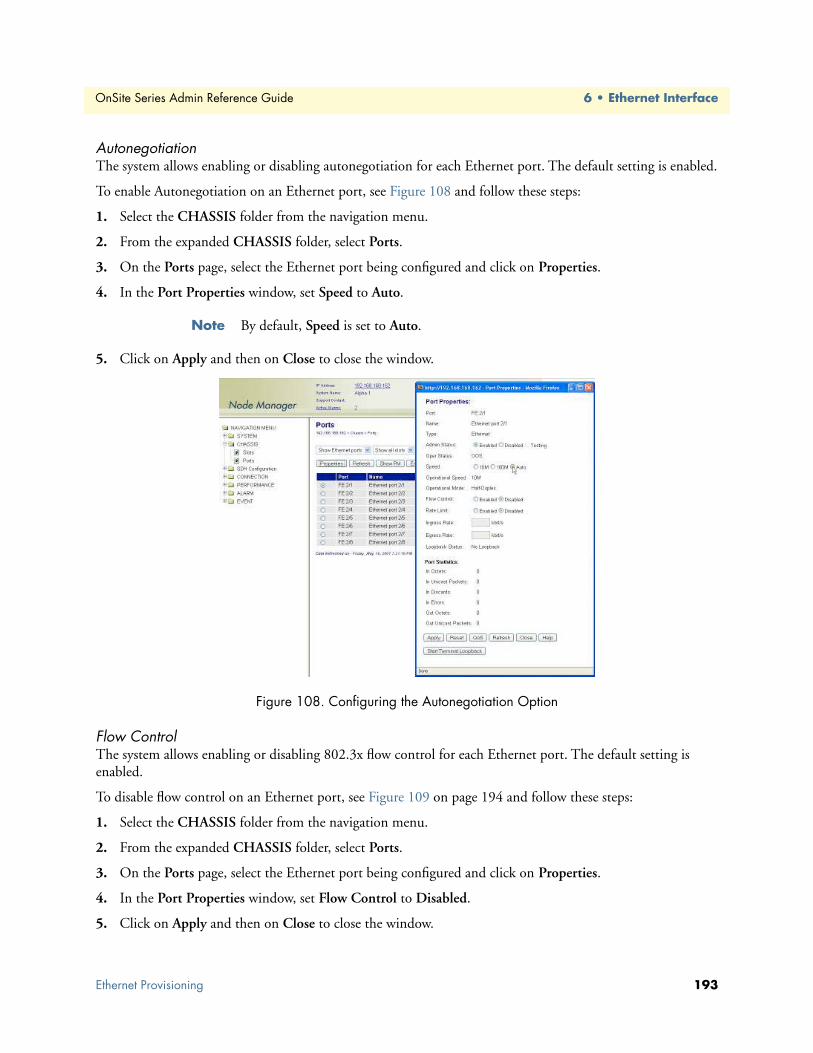
OnSite Series Admin Reference Guide 6 • Ethernet Interface
AutonegotiationThe system allows enabling or disabling autonegotiation for each Ethernet port. The default setting is enabled.
To enable Autonegotiation on an Ethernet port, see Figure 108 and follow these steps:
1. Select the CHASSIS folder from the navigation menu.
2. From the expanded CHASSIS folder, select Ports.
3. On the Ports page, select the Ethernet port being configured and click on Properties.
4. In the Port Properties window, set Speed to Auto.
Note By default, Speed is set to Auto.
5. Click on Apply and then on Close to close the window.
Figure 108. Configuring the Autonegotiation Option
Flow ControlThe system allows enabling or disabling 802.3x flow control for each Ethernet port. The default setting is enabled.
To disable flow control on an Ethernet port, see Figure 109 on page 194 and follow these steps:
1. Select the CHASSIS folder from the navigation menu.
2. From the expanded CHASSIS folder, select Ports.
3. On the Ports page, select the Ethernet port being configured and click on Properties.
4. In the Port Properties window, set Flow Control to Disabled.
5. Click on Apply and then on Close to close the window.
Ethernet Provisioning 193
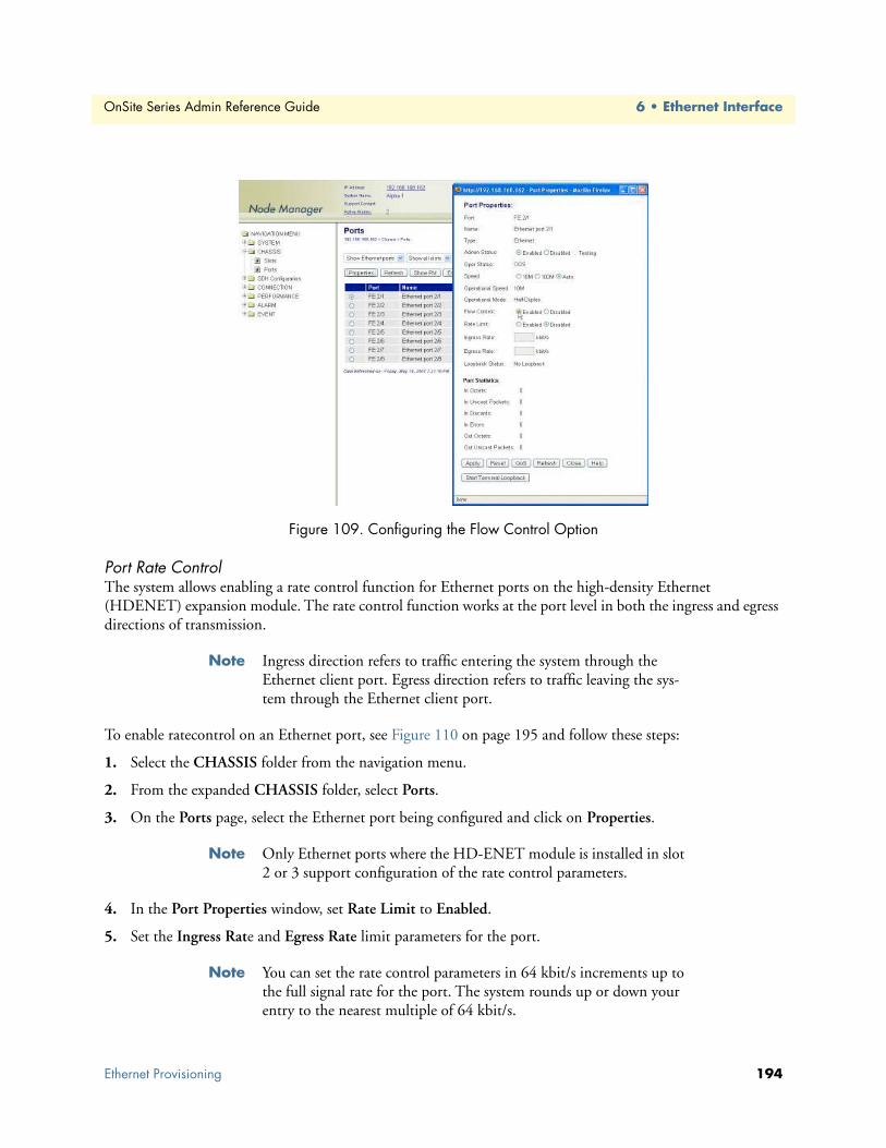
OnSite Series Admin Reference Guide 6 • Ethernet Interface
Figure 109. Configuring the Flow Control Option
Port Rate ControlThe system allows enabling a rate control function for Ethernet ports on the high-density Ethernet (HDENET) expansion module. The rate control function works at the port level in both the ingress and egress directions of transmission.
Note Ingress direction refers to traffic entering the system through the Ethernet client port. Egress direction refers to traffic leaving the sys-tem through the Ethernet client port.
To enable ratecontrol on an Ethernet port, see Figure 110 on page 195 and follow these steps:
1. Select the CHASSIS folder from the navigation menu.
2. From the expanded CHASSIS folder, select Ports.
3. On the Ports page, select the Ethernet port being configured and click on Properties.
Note Only Ethernet ports where the HD-ENET module is installed in slot 2 or 3 support configuration of the rate control parameters.
4. In the Port Properties window, set Rate Limit to Enabled.
5. Set the Ingress Rate and Egress Rate limit parameters for the port.
Note You can set the rate control parameters in 64 kbit/s increments up to the full signal rate for the port. The system rounds up or down your entry to the nearest multiple of 64 kbit/s.
Ethernet Provisioning 194
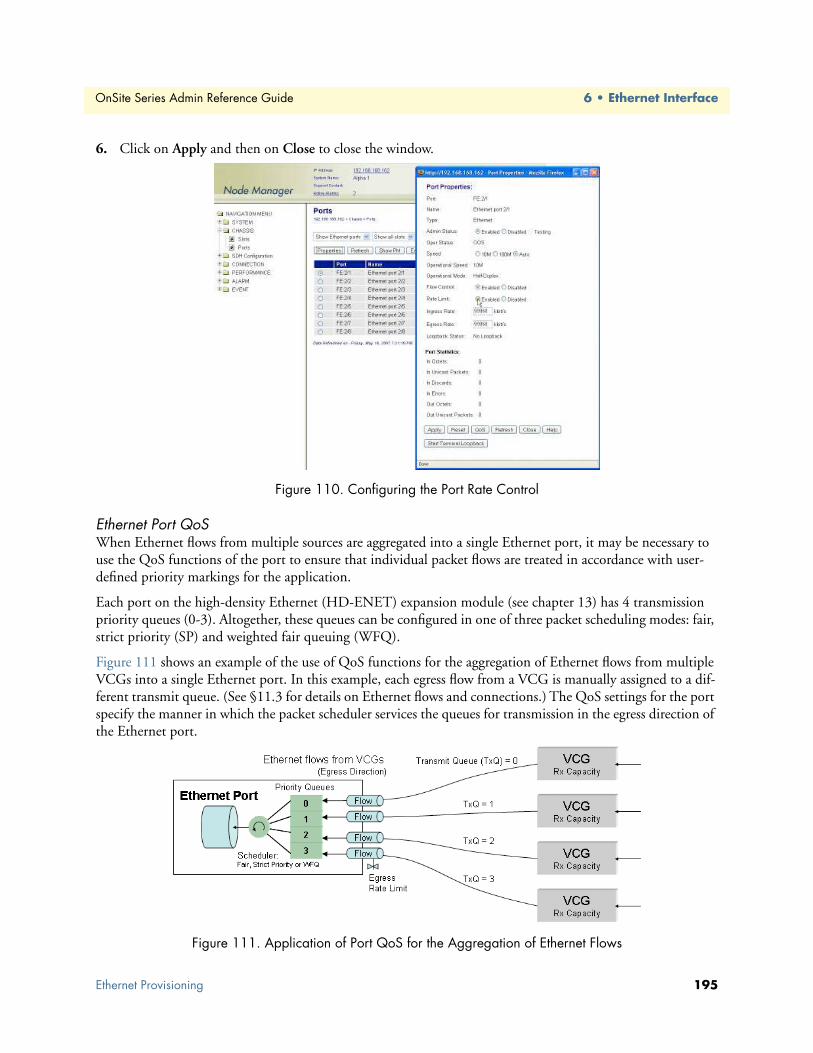
OnSite Series Admin Reference Guide 6 • Ethernet Interface
6. Click on Apply and then on Close to close the window.
Figure 110. Configuring the Port Rate Control
Ethernet Port QoSWhen Ethernet flows from multiple sources are aggregated into a single Ethernet port, it may be necessary to use the QoS functions of the port to ensure that individual packet flows are treated in accordance with user-defined priority markings for the application.
Each port on the high-density Ethernet (HD-ENET) expansion module (see chapter 13) has 4 transmission priority queues (0-3). Altogether, these queues can be configured in one of three packet scheduling modes: fair, strict priority (SP) and weighted fair queuing (WFQ).
Figure 111 shows an example of the use of QoS functions for the aggregation of Ethernet flows from multiple VCGs into a single Ethernet port. In this example, each egress flow from a VCG is manually assigned to a dif-ferent transmit queue. (See §11.3 for details on Ethernet flows and connections.) The QoS settings for the port specify the manner in which the packet scheduler services the queues for transmission in the egress direction of the Ethernet port.
Figure 111. Application of Port QoS for the Aggregation of Ethernet Flows
Ethernet Provisioning 195

OnSite Series Admin Reference Guide 6 • Ethernet Interface
To configure the QoS functions for an Ethernet port, see Figure 112 and follow these steps:
1. Select the CHASSIS folder from the navigation menu.
2. From the expanded CHASSIS folder, select Ports.
3. On the Ports page, select the Ethernet port being configured and click on Properties.
Note Only Ethernet ports where the HD-ENET module is installed in slot 2 or 3 support configuration of the port QoS functions.
4. In the Port Properties window, click on QoS.
5. In the Ethernet Port QoS Properties window set Queuing to Custom if you wish to configure the packet scheduler for operation in Strict Priority or WFQ mode.
– To configure the packet scheduler in Strict Priority mode, set Queue 0 Mode to Strict Priority. This change applies to all queues. (Strict Priority is the default setting for all queues.) Continue with Step 6 to complete this task.
In Strict Priority mode, the packet scheduler gives strict preference to packets in higher priority queues over packets in lower priority queues, regardless of the packet occupancy of individual queues. Among the four transmit queues, Queue 3 is the queue with the highest priority and Queue 0 is the queue with the lowest pri-ority.
– To configure the packet scheduler in WFQ mode, set Queue 0 Mode to WFQ. This change applies to all queues. Continue with Step 6 to complete this task.
In WFQ mode, the packet scheduler services the queues in accordance to a weight that you assign for each queue. The system requires that the sum of the weights for all four queues adds up to 100 percent.
6. Click on Apply and then on Close to close the Ethernet Port QoS Properties window.
7. Click on Close to close the Port Properties window.
Figure 112. Configuring the Ethernet Port QoS Function
Ethernet Provisioning 196
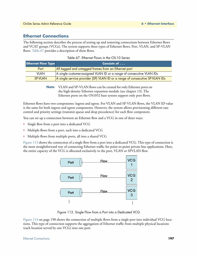
OnSite Series Admin Reference Guide 6 • Ethernet Interface
Ethernet ConnectionsThe following section describes the process of setting up and removing connections between Ethernet flows and VCAT groups (VCGs). The system supports three types of Ethernet flows: Port, VLAN, and SP-VLAN flows. Table 67 provides a description of these flows.
Note VLAN and SP-VLAN flows can be created for only Ethernet ports on the high-density Ethernet expansion module (see chapter 13). The Ethernet ports on the OS1052 base system support only port flows.
Ethernet flows have two components: ingress and egress. For VLAN and SP-VLAN flows, the VLAN ID value is the same for both ingress and egress components. However, the system allows provisioning different rate control and priority settings (transmit queue and drop precedence) for each flow component.
You can set up a connection between an Ethernet flow and a VCG in one of three ways:
• Single flow from a port into a dedicated VCG
• Multiple flows from a port, each into a dedicated VCG
• Multiple flows from multiple ports, all into a shared VCG
Figure 113 shows the connection of a single flow from a port into a dedicated VCG. This type of connection is the most straightforward way of connecting Ethernet traffic for point-to-point private line applications. Here, the entire capacity of the VCG is allocated exclusively to the port, VLAN or SPVLAN flow.
Figure 113. Single Flow from a Port into a Dedicated VCG
Figure 114 on page 198 shows the connection of multiple flows from a single port into individual VCG loca-tions. This type of connection supports the aggregation of Ethernet traffic from multiple physical locations (each location served by one VCG) into one port.
Table 67. Ethernet Flows in the OS-10 Series
Ethernet Flow Type Consists of . . .
Port All tagged and untagged frames from an Ethernet portVLAN A single customer-assigned VLAN ID or a range of consecutive VLAN IDs
SP-VLAN A single service provider (SP) VLAN ID or a range of consecutive SP-VLAN IDs
Ethernet Connections 197

OnSite Series Admin Reference Guide 6 • Ethernet Interface
Figure 114. Multiple Flows from a Port into Dedicated VCGs
Figure 115 shows the connection of multiple flows from multiple ports into a single VCG. This type of con-nection provides maximum bandwidth efficiency when you need to transport Ethernet traffic from multiple sources to a common destination and the service requirements permit the use of priority-based packet schedul-ing to ensure fair access to the shared VCG capacity.
Figure 115. Multiple Flows from Multiple Ports into a Shared VCG
VLAN and SP-VLAN ConnectionsFor VLAN flow connections, the system uses the customer-assigned VLAN tag (the C-Tag) to filter and con-nect Ethernet frames. You can configure the system to connect a single VLAN ID only or range of consecutive VLAN IDs. For example, in Figure 123, the system is configured to accept VLAN IDs 100 to 245. Only VLANs within the range are connected to the selected VCG.
Note The VLAN tag (or C-Tag) is defined by two values: the minimum and maximum VLAN IDs. You can use any value within the valid VLAN ID range of 0 to 4095. If both values are the same, the system selects only one VLAN ID instead of a range of consecutive VLAN IDs.
Ethernet Connections 198

OnSite Series Admin Reference Guide 6 • Ethernet Interface
Note The system uses the EtherType for a C-Tag (0x8100) together with the VLAN ID to decide whether or not an Ethernet frame belongs to a VLAN flow or not. The system drops Ethernet frames that match the specified VLAN ID value for the VLAN flow but that have an EtherType other than 0x8100.
Figure 116 also shows a port flow connection. In this case, the VLAN ID filter is turned off and passes all incoming frames from the port for mapping into the VCG.
Figure 116. Dedicated Ethernet Port and VLAN Flow Connections
As shown in Figure 117, the system allows the connection of multiple VLAN flows into a single VCG. In this case, the VLAN ID (or range of IDs) must be unique for each flow that is mapped into the shared VCG capac-ity. The system enforces this rule as you create VLAN flow connections.
Note The VLAN ID values need to be different to ensure flow separation within the VCG and allow the far-end system that terminates the VCG to extract and connect the incoming flows into the correct Ethernet ports.
Note When you first connect a VLAN flow into a VCG that contains no other connections (the VCG is empty), the system classifies the VCG as a “VLAN”-type VCG. From this point, the system does not allow additional connections into the VCG other than VLAN. The system opens the VCG to other types of connections with the removal of the last VLAN connection from the VCG.
Figure 117. Shared Ethernet VLAN Flow Connections
Ethernet Connections 199

OnSite Series Admin Reference Guide 6 • Ethernet Interface
For SP-VLAN flow connections, the system uses the service-provider VLAN tag (the S-Tag) to filter and con-nect Ethernet frames. You can configure the system to connect a single SP-VLAN ID only or range of consec-utive SP-VLAN IDs. For example, in Figure 125, the system is configured to accept SP-VLAN IDs 100 to 245. Only SP-VLAN IDs within the range are connected to the selected VCG.
Figure 118. Dedicated Ethernet SP-VLAN Flow Connection
The SP-VLAN tag (or S-Tag) is defined by two values: the minimum and maximum SPVLAN IDs. You can use any value within the valid SP-VLAN ID range of 0 to 4095. If both values are the same, the filter selects only one SP-VLAN ID instead of a range of consecutive SPVLAN IDs.
The system uses the EtherType for an S-Tag (0x88a8) together with the SP-VLAN ID to decide whether or not an Ethernet frame belongs to an SP-VLAN flow or not. The system drops Ethernet frames that match the spec-ified SP-VLAN ID value for the SP-VLAN flow but that have an EtherType other than 0x88a8.
As shown in Figure 119, the system allows the connection of multiple SP-VLAN flows into a single VCG. In this case, the SP-VLAN ID (or range of IDs) must be unique for each flow that is mapped into the shared VCG capacity. The system enforces this rule as you create SP-VLAN flow connections.
Figure 119. Shared Ethernet SP-VLAN Flow Connections
The SP-VLAN ID values need to be different to ensure flow separation within the VCG and allow the far-end system that terminates the VCG to extract and connect the incoming flows into the correct Ethernet ports.
When you first connect an SP-VLAN flow into a VCG that contains no other connections (the VCG is empty), the system classifies the VCG as an “SP-VLAN”-type VCG. From this point, the system does not allow additional connections into the VCG other than SP-VLAN. The system opens the VCG to other types of connection with the removal of the last SP-VLAN connection from the VCG.
Ethernet Connections 200

OnSite Series Admin Reference Guide 6 • Ethernet Interface
C-Tag ConnectionsIn addition to supporting the connection of native VLAN flows using the C-Tag information from an external source (such as a L2 switch or router), the system also lets you insert and remove a C-Tag that is fully under your control. This tagging operation is called “C-Tag Add/Strip.” When “C-Tag Add/Strip” is active, the OS-10 sytem performs two simultaneous functions for the selected Ethernet Port flow, as Table 68 indicates.
Note The system allows using the “C-Tag Add/Strip” tagging operation only for Ethernet Port flows. The operation is not available for VLAN and SP-VLAN flows.
Note When you tag a Port flow with a C-Tag, the system classifies the con-nection as a C-Tag connection inside a VCG.
As shown in Figure 120, the system supports multiple C-Tag connections into a single VCG. In this case, the C-Tag must be unique for each Port flow that is mapped into the shared VCG capacity. The system enforces this rule as you create C-Tag connections.
Figure 120. Shared Ethernet Port Flows Using C-Tag Connections
Note When you first make a C-Tag connection into a VCG that contains no other connections (the VCG is empty), the system classifies the VCG as a “C-Tag”-type VCG. From this point, the system does not allow additional connections into the VCG other than C-Tag. The system opens the VCG to other types of connection with the removal of the last C-Tag connection from the VCG.
Table 68. C-Tag Add/Strip Tagging Operation Functions
C-Tag Operation Applies to. . . Function
Add Ingress flow direction Insertion of C-Tag with VLAN ID specified by OS-10 userStrip Egress flow direction Removal of C-Tag with VLAN ID specificed by OS-10 user
Ethernet Connections 201

OnSite Series Admin Reference Guide 6 • Ethernet Interface
S-Tag ConnectionsIn addition to supporting the connection of native SP-VLAN flows using the S-Tag information from an exter-nal source (such as a L2 switch or router), the system also lets you insert and remove an S-Tag that is fully under your control. This tagging operation is called “S-Tag Add/Strip.” When “S-Tag Add/Strip” is active, the OS-10 performs two simultaneous functions for the selected Ethernet Port and VLAN flows, as Table 69 indi-cates.
Note The system allows using the “S-Tag Add/Strip” tagging operation only for Ethernet Port and VLAN flows. The operation is not avail-able for SP-VLAN flows.
When you tag a Port or VLAN flow with an S-Tag, the system classifies the connection as an S-Tag connection inside a VCG. For VLAN flows, the use of the S-Tag results in the insertion of a second VLAN tag for Q-in-Q tunneling.
As shown in Figure 121, you can use the S-Tag to combine multiple VLAN flows into a VCG, even when two or more flows have the VLAN ID number or range of IDs. The only requirement for the successful creation of a connection using the S-Tag is that the S-Tag number be unique within a VCG. The system enforces this rule as you create flow-based connections using the S-Tag.
Note The S-Tag values need to be different to ensure flow separation within the VCG and allow the far-end system that terminates the VCG to extract and connect the incoming flows into the correct Ethernet ports.
When you first make an S-Tag connection into a VCG that contains no other connections (the VCG is empty), the system classifies the VCG as an “S-Tag”-type VCG. From this point, the system does not allow additional connections into the VCG other than S-Tag. The system opens the VCG to other types of connec-tion with the removal of the last S-Tag connection from the VCG.
Figure 121. Shared Ethernet VLAN Flows Using S-Tag Connections
Table 69. S-Tag Add/Strip Tagging Operation Functions
S-Tag Operation Applies to. . . Function
Add Ingress flow direction Insertion of S-Tag with VLAN ID specified by OS-10 userStrip Egress flow direction Removal of S-Tag with VLAN ID specificed by OS-10 user
Ethernet Connections 202

OnSite Series Admin Reference Guide 6 • Ethernet Interface
You can also use the S-Tag to combine Ethernet traffic from multiple ports into a single VCG (see Figure 122). In this case, the S-Tag is applied to all frames from the port, whether the frames are tagged or untagged. If the frames are untagged, the S-Tag results in the equivalent insertion of a VLAN tag with EtherType 0x88a8 and an ID number that is fully under your control.
Figure 122. Shared Ethernet Port Flows Using S-Tag Connections
The S-Tag also provides the flexibility to combine a mix of Port and VLAN flows into a VCG, as shown in Figure 123.
Figure 123. Shared Ethernet Port and VLAN Flows Using S-Tag Connections
Table 70 on page 204 provides a summary of the tagging operations that you can apply for different types of Ethernet flows. Note that for Port flows, you can apply both the C-Tag and S-Tag Add/Strip operations, but for VLAN flows, you can only apply the S-Tag Add/Strip operation. For SP-VLAN flows, none of the tagging operations are allowed. Furthermore, the table summarizes the connection types that result from the applica-tion of the tagging operations.
Ethernet Connections 203

OnSite Series Admin Reference Guide 6 • Ethernet Interface
Creating a ConnectionThe following section contains the procedure for the connection of Ethernet flows into VCGs. The procedure starts with the steps to create a new Ethernet flow. Then, the procedure continues with the actual connection of the flow into one of the available VCGs.
To create an Ethernet flow, see Figure 124 on page 206 and follow these steps:
1. Select the CONNECTION folder from the navigation menu.
2. From the expanded CONNECTION folder, select Ethernet Flows.
3. On the Ethernet Flows page, click on Add Flow.
4. In the Add Flow window, select the ID number for the flow that you wish to create using the ID scroll-down button.
Note The system provides a list of the next available flow ID number for each Ethernet port in the system. For example, if there are no existing flows on port FE:3/8, the next available flow ID number for that port would be FE:3/8-1 (that is, the first flow). If, however, the port already has two flows configured, the system displays FE:3/8-3 as the next available flow ID number.
5. Type the Name for the flow if you wish to identify the new flow with an alphanumeric string. Otherwise, leave the field empty and continue with Step 6.
6. Select the Type of flow that you wish to create: Port, VLAN or SP-VLAN.
– Select Port if you wish to connect the entire port into a VCG.
– Select VLAN if you wish to connect a specified VLAN ID or range of VLAN IDs from the port into a VCG.
– Select SP-VLAN if you wish to connect a specified service provider (SP) VLAN ID or range of SP-VLAN IDs from the port into a VCG.
Note VLAN and SP-VLAN flows can be created for only Ethernet ports on the high-density Ethernet expansion module.
Table 70. Summary of Tagging Operations and Connections for Ethernet Flows
Ethernet Flow Type Allowed Tagging Operations
Connection Type into VCG
Port None PortC-Tag (Add/Strip) C-TagS-Tag (Add/Strip) S-Tag
VLAN None VLANS-Tag (Add/Strip) S-Tag
SP-VLAN None SP-VLAN
Ethernet Connections 204

OnSite Series Admin Reference Guide 6 • Ethernet Interface
7. If you select VLAN or SP-VLAN as the flow type in Step 6, type the Min VLAN ID and Max VLAN ID fields. Otherwise, go to Step 8.
Note The valid range of VLAN ID values is 0 to 4095. If you wish to select only one VLAN ID from the port, use the same value for Min VLAN ID and Max VLAN ID. If you wish to define the flow as a range of consecutive VLAN IDs from the port, use different values for Max VLAN ID and Min VLAN ID. You can use any VLAN ID values within the valid range of 0 to 4095. For SP-VLAN flows, the system uses the S-Tag to filter and connect Ethernet packets with the speci-fied VLAN ID values and with EtherType value of 0x88a8.
The system filters incoming Ethernet traffic according to the specified VLAN settings. All untagged Ethernet frames are dropped, and only VLAN-tagged frames within the specified Min VLAN ID and Max VLAN ID range are allowed to pass through.
8. If you wish to limit the rate at which the flow is connected to a VCG, set Rate Control to Enabled and type the Sustained Rate and Peak Rate parameters for both the ingress and egress directions of transmis-sion. You can set the rate control parameters in 64 kbit/s increments up to the full signal rate for the port. The system rounds up or down your entry to the nearest multiple of 64 kbit/s.
9. If you plan to connect this flow to a VCG that contains other flows (that is, a shared VCG), select the Transmit Queue and Drop Precedence for both the ingress and egress directions of transmission.
For the Ingress component of the flow (that is, from the Ethernet client port towards the VCG), the Transmit Queue indicates the queue number of the VCG into which the system connects the flow. The system uses the QoS settings of the VCG to schedule packet transmission from the queues towards the VCG capacity.
For the Egress component of the flow (that is, from the VCG towards the Ethernet client port), the Transmit Queue indicates the queue number of the Ethernet port into which the system connects the flow. The system uses the QoS settings of the Ethernet port to schedule packet transmission from the queues towards the Ether-net port capacity. (See §11.2.3.4 for details on configuring the QoS settings of an Ethernet port.)
For each flow component, the Drop Precedence indicates whether the frames belonging to the flow are of high-drop or low-drop classification. The system uses WRED (weighted random early discard) to discard frames in a gradual, graceful, and randomly selected manner before internal congestion occurs. The system drops frames with High drop precedence with higher probability than frames with Low drop precedence.
10. Click on Apply and then on Close to close the window.
At this point, the flow is configured for service and is ready for connection to a selected VCG.
Ethernet Connections 205

OnSite Series Admin Reference Guide 6 • Ethernet Interface
Figure 124. Creating an Ethernet Flow
To connect an Ethernet flow to a VCG, see Figure 125 on page 207 and follow these steps:
1. Select the CONNECTION folder from the navigation menu.
2. From the expanded CONNECTION folder, select Client Port Mappings.
3. On the Client Port Mappings page, use the Create Mapping Options... scroll-down button to select the Create Ethernet Mapping option.
Note If no Ethernet flows are available for new connections, the system responds with a warning message. You can proceed only if there are any existing flows that remain unconnected within the system.
4. In the Create Ethernet Mapping window, select the VCAT group to which you wish to connect the Ether-net flow using the VCG ID scroll-down button.
Note If no flow matches the selected VCG ID, the system responds with a warning message. Change the VCG ID selection until the Flow ID presents a list of flows that contains the flow that you wish to connect to the VCG.
5. Select the Ethernet flow that you wish to connect, using the Flow ID scroll-down button.
Note The flow Type indicates whether the selected flow is a port, VLAN or SP-VLAN flow and the VLAN ID range for VLAN and SP-VLAN flows.
Ethernet Connections 206

OnSite Series Admin Reference Guide 6 • Ethernet Interface
6. If you wish to connect the flow to the VCG using an S-Tag, set Tagging Operation to S-Tag (Add/Strip) and type the Tag ID for the S-VID (0 to 4095). On the other hand, if you wish to connect the flow to the VCG using a C-Tag, set Tagging Operation to C-Tag (Add/Strip) and type the Tag ID for the C-VID (0 to 4095). Otherwise, for non-tagged connections, leave Tagging Operation as None.
Note The S-Tag (or C-Tag) ID value must be unique within the VCG if the VCG already supports other flow connections that use the S-Tag (or C-Tag).
7. If you wish to connect the flow to the VCG as a 2-way (bidirectional) connection, leave Direction as 2-way. However, for 1-way (unidirectional) connections, set Direction to 1-way, and set the Connection Point button for VCAT Group (VCG) to indicate whether the VCG is the Sink or Source point for the connection.
For drop-and continue connections, set Direction to either 1-way drop-continue or 2-way drop-continue.
For multicast connections, set Direction to 1-way multicast.
If you plan to drop Ethernet traffic from a single VCG into more than one Ethernet port in the same expan-sion slot, you must first start with the creation of a single 1-way multicast connection (and not with a regular 1-way connection) between the source VCG and the first of the Ethernet sink ports. Once the first multicast connection is present, you can add other multicast connection legs between the same VCG and other sink ports in the slot.
For Drop-and-continue and multicast connections, the system requires that the VCG is the source point of the connection.
8. Click on Apply and then on Close to close the widow.
At this point, the Client Port Mappings page displays the new connection between the selected flow and VCG. For each flow connection, the Connection Type indicates whether a flow connects to the VCG at the Port, VLAN, SP-VLAN, C-Tag, or S-Tag level. The Ethernet ports on the base OS1052 system support the use of the C-Tag and S-Tag Add/Strip operations.
Figure 125. Connecting an Ethernet Flow to a VCG
Ethernet Connections 207

OnSite Series Admin Reference Guide 6 • Ethernet Interface
Removing a ConnectionTo remove an existing Ethernet flow-to-VCG connection, see Figure 126 and follow these steps:
1. Select an Ethernet port connection on the Client Port Mappings page.
2. Select Delete a Single Mapping using the Delete Mapping Options... scroll-down button.
At this point, the system removes the connection and it is no longer displayed in the table.
Figure 126. Removing an Ethernet Flow from a VCG
Ethernet AlarmsThe following section describes the process for monitoring alarms that may be present on Ethernet ports and the process of changing the default alarm settings.
Monitoring Port AlarmsTable 71 provides a list of the alarms that the system monitors at the Ethernet port level.
Note The system declares and displays an alarm condition if a defect per-sists for 2.5 ± 0.5 seconds. The alarm condition is cleared when the defect is terminated and remains absent for 10 ± 0.5 seconds.
Two LEDs are present for each port on the base system to indicate link status and activity. The LEDs are lit according to the color codes in Table 72.
Table 71. Ethernet Port Alarms
Alarm Description
Ethernet Link Down Ethernet link is downEthernet Buffer Overflow Buffer has overflowedEthernet Loopback Buffer has overflowed
Table 72. Status LED for Ethernet Ports on the Base System
LED Type LED Color LED Is On LED Is Off
Link Green Ethernet link is up Ethernet link is downActivity Amber Blinks when there is Ethernet traffic on link No Ethernet traffic on link
Ethernet Alarms 208

OnSite Series Admin Reference Guide 6 • Ethernet Interface
To display Ethernet alarms, if present, see Figure 127 and follow these steps:
1. Select the ALARM folder from the navigation menu.
2. From the expanded ALARM folder, select Show Active Alarms.
At this point, the Active Alarms page displays all active alarms in the system, including Ethernet alarms, if present. Table 73 describes the fields for each Ethernet alarm entry. The table contains a separate entry for each active Ethernet alarm. Each entry includes the following fields:
Note The system automatically updates the Active Alarms page every 60 seconds. Click on Refresh if you need to update the table with the most recent active alarm information. Individual table entries auto-matically clear whenever previously active alarms are no longer present.
Figure 127. Displaying Ethernet Port Alarms
Changing Port Alarm Default SeveritiesTable 74 provides the default severities for Ethernet port alarms:
Table 73. Table Entries for Active Ethernet Alarms
Table Entry for Active Alarms Field Value
Type Link Down, Buffer Overflow, or LoopbackAlarm Raised Time Date and time
Severity Critical, Major, Minor, or WarningDetailed Information Location of affected Ethernet port (FE:slot/port)
Table 74. Ethernet Line Alarm Default Severities
Monitored Entity Near-end Alarm Default Severity
Ethernet port Link Down CriticalEthernet port Buffer Overflow MajorEthernet port Loopback Minor
Ethernet Alarms 209

OnSite Series Admin Reference Guide 6 • Ethernet Interface
To change the default severity for supported Ethernet alarms, see Figure 128 and follow these steps:
1. Select the ALARM folder from the navigation menu.
2. From the expanded ALARM folder, select Set Alarm Severity.
At this point, the Alarm Severity page displays a table with all supported system alarms.
3. Select the table entry containing the Ethernet port alarm Type and click on Change.
4. In the Alarm Severity window, set Severity to any desired level (Critical, Major, Minor, or Warning).
5. Click on Apply and then on Close to close the window.
On the Alarm Severity page, the Severity for the selected Ethernet port alarm Type should now reflect the change in the reported severity level.
Note The change applies to all Ethernet ports within the system.
Figure 128. Changing Ethernet Port Alarm Settings
Ethernet Port StatisticsThe following section describes the process for displaying current traffic statistics for Ethernet ports.
The system collects performance statistics at the Ethernet port level, as listed in Table 75.
Table 75. Ethernet Port Statistics
Parameter Monitoring Direction
Octets Incoming and outgoingUnicast packets Incoming and outgoing
Errors Incoming onlyDiscards Incoming only
Ethernet Port Statistics 210

OnSite Series Admin Reference Guide 6 • Ethernet Interface
To display the current performance statistics for an Ethernet port, see Figure 129 and follow these steps:
1. Select the CHASSIS folder from the navigation menu.
2. From the expanded CHASSIS folder, select Ports.
3. On the Ports page, select the Ethernet port being monitored and click on Properties.
Note The system displays the performance statistics for the selected Ether-net port. The system uses 32-bit counters for all monitored parame-ters. The window content is not updated automatically as new counts occur. Click on Refresh if you need to update the window content with the most recent count information.
4. Click on Close to close the window.
Note You can also display the current performance statistics by clicking on Show PM on the Ports page after selecting one of the Ethernet ports.
Figure 129. Displaying Ethernet Port Statistics
To display the Ethernet counters for all enabled Ethernet ports, follow these steps:
1. Select the PERFORMANCE folder from the navigation menu.
2. From the expanded PERFORMANCE folder, select Counters.
3. From the expanded Counters folder, select Ethernet.
At this point, the system displays the performance statistics for all enabled Ethernet ports. The table is empty when no ports are enabled.
Note The system uses 32-bit counters for all monitored parameters.
To clear the counters for a port, select the port entry on the table and then click on Clear Statistics.
Note The table content is not updated automatically as new counts occur. Click on Refresh if you need to update the table content with the most recent count information.
Ethernet Port Statistics 211

OnSite Series Admin Reference Guide 6 • Ethernet Interface
Ethernet TestingThe following section provides the procedures for enabling and disabling loopback tests for Ethernet ports.
The OS-10 system supports terminal loopback for Ethernet ports. As shown in Figure 130, while the terminal loopback is active, the Ethernet signal is looped back towards the STM-1 interface just before transmission on the Ethernet PHY. The idle sequence is also transmitted on the physical port. Terminal loopback allows the testing of the performance and connectivity for an Ethernet service across the SDH network.
Figure 130. Ethernet Terminal Loopback
To start an Ethernet terminal loopback test, see Figure 131 on page 213 and follow these steps:
1. Select the CHASSIS folder from the navigation menu.
2. From the expanded CHASSIS folder, select Ports.
3. On the Ports page, select the Ethernet port being tested and click on Properties.
4. In the Port Properties window, click on Start Terminal Loopback.
A warning window opens to alert you to the start of the loopback test. Click on OK to continue or Cancel to cancel the request.
Loopback Status on the Port Properties window changes to Terminal Loopback Active. Admin Status for the port changes to Testing.
5. Click on Close to close the Port Properties window.
Starting an Ethernet terminal loopback causes traffic disruption if the Ethernet port is already connected to a VCG.
WARNING
Ethernet Testing 212

OnSite Series Admin Reference Guide 6 • Ethernet Interface
Figure 131. Activating Ethernet Port Terminal Loopback
Ethernet Testing 213

Chapter 7 High-Density E1 Expansion Module
Chapter contentsIntroduction ........................................................................................................................................................215Installing the HD-E1 Module .............................................................................................................................218Provisioning the HD-E1 Module ........................................................................................................................219Module Alarms....................................................................................................................................................221Timing Features on the HD-E1 Module .............................................................................................................221
Derived Timing from E1 Line ......................................................................................................................221External Timing Inputs .................................................................................................................................222Retiming Mode .............................................................................................................................................222
Downloading Expansion Module Firmware ........................................................................................................223
214

OnSite Series Admin Reference Guide 7 • High-Density E1 Expansion Module
IntroductionAs an option, the system allows the installation of a high-density E1 (HD-E1) expansion module for applica-tions requiring additional E1 drop capacity. Figure 132 provides a front-side view of the module.
Figure 132. HD-E1 Module
The HD-E1 expansion module has 21 E1 interfaces and supports 120-ohm (balanced) and 75-ohm (unbal-anced) terminations as factory-installed options. E1 signals comply with the specifications in G.703. Table 76 shows the product codes that identify which type of termination is supported. The product code is located on the front plate of the module.
The module weighs approximately 0.2 kg (0.5 lbs) and has the following dimensions: 38 x 101 x 167 mm (height x weight x depth). E1 ports are connected to individual TU-12 time slots using asynchronous mapping into VC-12 containers, as specified in ITU-T Recommendation G.707.
The module uses a high-density Future Bus connector on the front panel. The connector is divided into six sections. Each section supports bidirectional transmission of four E1 ports. Connector section 6, however, sup-ports only one E1 port for a combined total of 21 E1 ports. Table 77 provides the port assignments for E1 ports on the Future Bus connector.
Table 76. Product Codes for the HD-E1 Module
Code Interface Termination
9100-E1-075-21 21 E1 75-ohm9100-E1-120-21 21 E1 120-ohm
Introduction 215

OnSite Series Admin Reference Guide 7 • High-Density E1 Expansion Module
Each Future Bus connector section has 24 pins. Table 78 shows the pin layout of a connector section. The table columns represent the physical location of the connector section pins when viewed from the front.
Note TXP and TXN correspond to the positive (tip) and negative (ring) pins for the transmit signal. RXP and RXN correspond to the receive side of the signal.
For physical interconnection between the module and other equipment, you need special cables. These cables have to be ordered separately, and the type and length of each cable has to be specified at the moment that you order the module.
• For 75-ohm interfaces, each cable supports connectivity for four E1 ports. The cable provides eight BNC connectors (four transmit and receive pairs) on one end and a single Future Bus plug on the other end. You can connect the Future Bus plug to any available connector section on the module.
• For 120-ohm interfaces, each cable supports connectivity for four E1 ports. One side of the cable contains twisted-pair wires (four transmit and receive pairs) that you can use for direct termination on an MDF (wire-wrap) or four RJ-48 connectors. The size of the twisted-pair cables is 28 AWG (or 4 mm). The cable has a single Future Bus plug on the other end. You can connect the Future Bus plug to any available connec-tor section on the module. You can also bind together three cables and terminate the E1 signals on a single RJ-21 Telco connector (12 transmit and receive pairs). Table 79 on page 217 provides the connector pin-out assignments for 12 E1 ports using the RJ-21 Telco connector termination. For this 12-port E1 cable configuration, it is recommended that you connect the three Future Bus plugs to three consecutive connec-tor sections, either in sections 1 through 3 or 4 through 6.
Table 77. E1 Port Assignments for Future Bus Connector Sections
Connector Section E1 Ports
1 1-42 5-83 9-124 13-165 17-206 21
Table 78. Pin Assignment in a Future Bus Connector Section
Connector Section Pin Column
1 2 3 4 5 6
TXP-1 TXN-2 TXP-2 TXN-3 TXP-3 TXN-4TXN-1 – – – TXP-4RXN-1 – – – RXP-4RXP-1 RXN-2 RXP-2 RXN-3 RXP-3 RXN-4
Introduction 216

OnSite Series Admin Reference Guide 7 • High-Density E1 Expansion Module
Table 79. Pin Assignments for E1 Ports 1–12 and 13–21 Using a 50-Pin Telco ConnectorE1 Port Tip Connector Pins Ring
1 TX 1 26 TXRX 2 27 RX
2 TX 3 28 TXRX 4 29 RX
3 TX 5 30 TXRX 6 31 RX
4 TX 7 32 TXRX 8 33 RX
5 TX 9 34 TXRX 10 35 RX
6 TX 11 36 TXRX 12 37 RX
7 TX 13 38 TXRX 14 39 RX
8 TX 15 40 TXRX 16 41 RX
9 TX 17 42 TXRX 18 43 RX
10 TX 19 44 TXRX 20 45 RX
11 TX 21 46 TXRX 22 47 RX
12 TX 23 48 TXRX 24 49 RX– 25 50 –
13 TX 1 26 TXRX 2 27 RX
14 TX 3 28 TXRX 4 29 RX
15 TX 5 30 TXRX 6 31 RX
16 TX 7 32 TXRX 8 33 RX
17 TX 9 34 TXRX 10 35 RX
18 TX 11 36 TXRX 12 37 RX
19 TX 13 38 TXRX 14 39 RX
20 TX 15 40 TXRX 16 41 RX
21 TX 17 42 TXRX 18 43 RX– 19 44 –– 20 45 –– 21 45 –– 22 46 –– 23 48 –– 24 49 –– 25 50 –
Introduction 217

OnSite Series Admin Reference Guide 7 • High-Density E1 Expansion Module
Installing the HD-E1 ModuleThe HD-E1 module supports hot swapping. You can insert the module into or remove it from any available expansion slot of the chassis while the system is powered on and carrying traffic.
To install the HD-E1 module, see Figure 133 and follow these steps:
1. Remove the front plate cover for the slot in which you wish to install the module. Turn each mounting screw in a counterclockwise direction until the cover is fully released from the chassis.
2. Remove the HD-E1 module from the ESD bag, and place it on a flat, clean and dry surface (use a grounded antistatic mat, if possible).
Note Set the ESD bag aside for reuse in case you need it to replace and return the module in the future.
3. Align the module with the card guides inside the slot and slide the module slowly into the slot.
4. Push the front plate (gently applying force on each side of the plate at the same height as the guide rail) until the module is securely snapped in place. The front plate should be flush with the front panel of the OS-10 system.
5. Secure the module to the chassis by turning the two mounting screws on the front panel of the module in a clockwise direction.
At this point, use the OnSight Device Manager to set the Administrative Type for the slot in which the mod-ule resides to 21-port E1 expansion module. The STAT LED of the HD-E1 module becomes a solid green light when the Administrative Status of the module is enabled and Operational Status is in service (IS).
Figure 133. Installing the HD-E1 Module
Be careful to maintain the alignment along the card cage guide rail axis as you insert the module. Do not rotate or pull the mod-ule up or down during the insertion procedure or you may risk breaking the module. Make sure that the mezzanine board clears the hole plates on each side of the slot aperture.
CAUTION
Installing the HD-E1 Module 218

OnSite Series Admin Reference Guide 7 • High-Density E1 Expansion Module
Provisioning the HD-E1 ModuleTo provision the HD-E1 module, see Figure 134 on page 220 and follow these steps:
1. Select the CHASSIS folder from the navigation menu.
2. From the expanded CHASSIS folder, select Slots.
3. On the Slots page, check that the Status for the slot in which the module resides is Full.
Note On the Slots page, the Status indicates the presence of a module in the expansion slots. When a module is physically present and prop-erly inserted in slot 2 or 3, the table entry shows Full for that slot. Otherwise, the table entry shows Empty.
4. Check that the Operational Type for the slot shows: 21-port E1 expansion module.
Note The Operational Type indicates the type of module in the slot. The table entry shows 21-port E1 expansion module when the system has software access and control for the HD-E1 module. Otherwise, the entry shows Unknown, even when the module is physically present in the slot.
Note When the Operational Type is Unknown and the module is securely installed in the chassis, the module may need replacement. Consult your nearest support center or systems engineer servicing the system for technical support.
5. Select the Slot ID for the slot in which the module resides, and click on Properties.
6. In the Slot Properties window, set the Administrative Type to 21-port E1 expansion module using the scroll-down button.
7. Set the Administrative Status to Enabled.
8. Click on Apply for the settings to take effect.
Note You can also use the Slot Properties window to check the inventory for the module, including the hardware description, manufacturing part number (MFG P/N) and revision. You can also use the Slot Properties window to verify that the module completed the POST.
9. Click on Close to close the window and finish this task.
At this point, the module is now ready for the provisioning of E1 services using the OnSight Device Manager or NMS.
Provisioning the HD-E1 Module 219

OnSite Series Admin Reference Guide 7 • High-Density E1 Expansion Module
Figure 134. Provisioning the HD-E1 Module
Note The system displays all E1 ports in slot 2 and slot 3 when the Admin-istrative Type for those slots is set to Enabled. The module need not be physically present in the slot for the system to display the ports on the Ports page.
You can preconfigure E1 port mappings before the module is physically present in the slot.
The system maintains all existing E1 expansion port mappings in the Client Port Mappings connection table even after physical removal of the module from the slot.
Save the system configuration to prevent the loss of the module settings if a system reboot occurs
CAUTION
Provisioning the HD-E1 Module 220

OnSite Series Admin Reference Guide 7 • High-Density E1 Expansion Module
Module AlarmsTable 80 provides a list of the alarms that the system monitors for the HD-E1 module.
The alarm (ALM) status LED indicates the presence of an active alarm condition of any severity level on any of the 21 E1 ports on the HD-E1 module. The LED is lit according to the color codes in Table 81.
Timing Features on the HD-E1 ModuleThe following section describes the timing features of the HD-E1 module. The module supports all the E1 timing functions, except for Sync Out. Table 82 notes the differences between the timing features supported by the E1 ports on the OS1052 and OS1063 base systems and the HD-E1 expansion module.
Derived Timing from E1 LineTo configure the system to use E1 ports 20 and 21 from a HD-E1 module as the primary and secondary refer-ences for synchronization using line timing, follow these steps:
1. Select the SYSTEM folder from the navigation menu.
2. From the expanded SYSTEM folder, select Timing & Sync.
3. On the Timing & Synchronization page, select Auto: E1 port 2/20, port 2/21 using the Timing Mode – Primary/Secondary Source scroll-down button.
4. Click on Apply for the changes to take effect.
Table 80. Module Alarms
Alarm Name Default Severity Occurs when the . . .
Card Initialization Failed Critical Module fails the POST.Card Failure Critical System fails to access the hardware correctly.Card Missing Critical System fails to access the hardware correctly.Card Mismatched Critical Administrative and operational types are different.Card Mismatched Major Software cannot support the current version of hardware.
Table 81. ALM (Alarm Status) LED for the HD-E1 Module
LED Color Description
Green No alarm is present on any port.Amber An alarm is present on one or more ports.
Off All E1 ports are disabled.
Table 82. Timing Feature Differences for E1 Ports on the OS-10 and the HD-E1 Module
E1 Ports in the
E1 Line Timing Is On
Sync In Is On
Sync Out Is On
OS1052 base system Ports 7–8 Ports 7–8 Ports 7–8OS1063 base system Ports 20-21 Ports 20-21 Ports 20-21
HD-E1 module Ports 20-21 Ports 20-21 –
Module Alarms 221

OnSite Series Admin Reference Guide 7 • High-Density E1 Expansion Module
Note The system does not allow the change of the timing mode directly from one primary-and secondary-timing-source pair to another. You must first change the timing mode to Internal and then to Auto: E1 port 2/20, port 2/21.
• By default, E1 ports 20 and 21 are configured for carrying regular E1 traffic. In the “traffic” mode, the system uses the derived 2.048-MHz clock from the E1 lines as timing references for synchroniza-tion. You can view the current port signal mode in the Ports page or Port Properties window for E1 ports 20 and 21.
External Timing InputsTo configure E1 ports 20 and 21 as external timing inputs for synchronization (Sync In), follow these steps:
1. Go through the steps in “Configuring a Port for Synchronization” on page 150, but use E1:slot/20 (instead of E1:1/7) and E1:slot/21 (instead of E1:1/8) for the procedure. Change the port signal mode for these ports to Sync In.
Note The slot refers to the expansion slot in which the module resides. The Port Properties window for E1 ports 20 and 21 provides the same configuration options as that for E1:1/7 and E1:1/8.
2. Go through the steps in “Derived Timing from E1 Line” on page 221 to configure the system to use E1:slot/20 and E1:slot/21 as the timing references for synchronization.
Retiming ModeThe HD-E1 module supports a retiming function for E1 ports 1-8, individually. In the regular mode of opera-tion, the module uses the recovered clock from the demapped E1 signal for transmission into the physical E1 line. In the retiming mode, however, the module uses the system clock to transmit the E1 signal. You may use the retiming mode to distribute system timing to other equipment (such as PBXs or BTSs) that connects to the OS-10 at the E1 line level using the HD-E1 module.
To enable the retiming feature for E1 ports 1-8 in the HD-E1 module, follow these steps:
1. Select the CHASSIS folder from the navigation menu.
2. From the expanded CHASSIS folder, select Ports.
3. On the Ports page, select E1:slot/port and click on Properties.
Note The retiming function of an HD-E1 module in slot 2 or 3 is available only for E1 port numbers 1-8.
4. In the Port Properties window, set Retiming to Enabled.
5. Click on Apply and then on Close to close the window.
Timing Features on the HD-E1 Module 222

OnSite Series Admin Reference Guide 7 • High-Density E1 Expansion Module
Downloading Expansion Module FirmwareTo download and install new firmware into the expansion modules, see Figure 135 on page 224 and follow these steps:
Note This procedure applies only when the system is equipped with one or two expansion modules and a new firmware upgrade is required.
1. Select the CHASSIS folder from the navigation menu.
2. From the expanded CHASSIS folder, select Slots.
3. On the Slots page, select the expansion module that requires the new firmware and click on Properties. Slot 2 and slot 3 are the respective slots for expansion modules 1 and 2. Slot 1 corresponds to the base OS-10 system.
4. On the Slot Properties page, click on Download Firmware.
5. In the Download Expansion Module Firmware window, set Transfer Protocol to FTP or TFTP. FTP is the default transfer protocol. FTP and TFTP work on Windows, UNIX, and Linux servers.
6. Type the Host Pathname to indicate the name of the firmware image file to be retrieved and its location within the host server.
Note You must specify either the full or relative pathname from the server root directory to indicate the location of the firmware image file. The file name for the firmware image must contain the .img extension.
7. Type the Server IP Address of the host server containing the firmware image file.
8. Type the User Name and Password for secure access to the file. In this step, you must enter the user name and password, as demanded by the server access permission.
9. Click on Apply to initiate the file transfer between the server and OS-10 system.
At this point, the system indicates the download progress in Transfer Progress (%). The firmware download operation may take a few minutes to complete. The new firmware takes effect after completion of the next sys-tem reboot. You can also activate the new firmware immediately by clicking on Module Reset at the bottom of the window.
Make sure that the Transfer Result indicates Success and transfer is 100-per-cent complete before rebooting the system or resetting the module. If the transfer result is Fail, keep trying to download the firmware until the result is Success. In addition, do not power cycle the system or reset the module while the download is in progress. Rebooting the system or resetting the module with a corrupted firmware image makes the module permanently inoperative and requires module replacement.
WARNING
Downloading Expansion Module Firmware 223

OnSite Series Admin Reference Guide 7 • High-Density E1 Expansion Module
Figure 135. Download Firmware into the Expansion Modules
After installation of the new firmware is complete, check that the Slot Properties window indicates a change in the firmware Revision field (that is, from the old firmware revision code to the new code). If the firmware revision code remains as before, click on the Module Reset button until Revision indicates a change to the new code. Otherwise, the new firmware is not installed and operational.
CAUTION
Downloading Expansion Module Firmware 224

Chapter 8 High-Density Ethernet Expansion Module
Chapter contentsIntroduction ........................................................................................................................................................226Installing the HD-ENET Module .......................................................................................................................227Provisioning the HD-ENET Module ..................................................................................................................228Module Alarms....................................................................................................................................................230Downloading Expansion Module Firmware ........................................................................................................230
225

OnSite Series Admin Reference Guide 8 • High-Density Ethernet Expansion Module
IntroductionAs an option, the system allows the installation of a high-density Ethernet (HD-ENET) expansion module for applications that require access to additional Ethernet ports together with enhanced virtual concatenation (VCAT) and flexible Layer 2 functions. Figure 136 provides a front-side view of the module.
Figure 136. HD-ENET Module
The HD-ENET module has eight Ethernet 10/100BASE-TX interfaces. The module weighs approximately 0.2 kg (0.5 lbs) and has the following dimensions: 38 x 101 x 167 mm (height x weight x depth).
Ethernet traffic is mapped into VCAT Groups (VCGs) using GFP encapsulation, as specified in ITU-T Rec-ommendations G.7041/Y.1303 and G.707. The module supports up to 16 VCGs.
The Ethernet ports comply with the following standards:
• IEEE 802.3u (PHY)
• IEEE 802.3 (MAC)
• IEEE 802.3x (flow control)
The module supports Ethernet frames in the following range: 64 to 1,600 bytes.
Note The Ethernet ports on the base OS1052 system support jumbo frames up to 9,600 bytes.
Table 83 provides the cabling specifications for the Ethernet ports.
Table 83. Ethernet Port Cabling Specifications
Cable Specification
Connector RJ-45Type Category 5
Reach 100 m
Introduction 226

OnSite Series Admin Reference Guide 8 • High-Density Ethernet Expansion Module
Table 84 provides the pin assignment for the Ethernet RJ-45 connector.
Installing the HD-ENET ModuleThe HD-ENET module supports hot swapping. You can insert the module into or remove it from any avail-able expansion slot of the chassis while the system is powered on and carrying traffic. This process does not result in the loss or disruption of existing traffic on the system.
To install the HD-ENET module, see Figure 137 on page 228 and follow these steps:
Note Although not required, you may power down the system before start-ing the module insertion procedure.
1. Remove the front plate cover for the slot in which you wish to install the module. Turn each mounting screw in a counterclockwise direction until the cover is fully released from the chassis.
2. Remove the HD-ENET module from the ESD bag and place it on a flat, clean, and dry surface (use a grounded antistatic mat, if possible).
Note Set the ESD bag aside for reuse in case you need it to replace and return the module in the future.
3. Align the module with the card guides inside the slot and slide the module slowly into the slot.
4. Push the front plate (gently applying force on each side of the plate at the same height as the guide rail) until the module is securely snapped in place. The front plate should be flush with the front panel of the OS-10 system.
5. Secure the module to the chassis by turning the two mounting screws on the front panel of the module in a clockwise direction.
The STAT LED of the HD-ENET module becomes a solid amber light for about 10 seconds after the system detects the module. At this point, use the OnSight Device Manager to set the Administrative Type for the slot in which the module resides to 8-port Ethernet expansion module. The STAT LED of the module becomes a solid green light when the Administrative Status of the module is enabled and the Operational Status is in ser-vice (IS).
Table 84. Ethernet Port Pin Assignment (RJ-45 Connector)
Signal Name Description RJ-45 Pin
RXN Receive ring 6RXP Receive tip 3TXN Transmit ring 2TXP Transmit ring 1
Be careful to maintain the alignment along the card cage guide rail axis as you insert the module. Do not rotate or pull the mod-ule up or down during the insertion procedure, or you may risk breaking the module.CAUTION
Installing the HD-ENET Module 227

OnSite Series Admin Reference Guide 8 • High-Density Ethernet Expansion Module
Figure 137. Installing the HD-ENET Module
Provisioning the HD-ENET ModuleTo provision the HD-ENET module, see Figure 138 on page 229 and follow these steps:
1. Select the CHASSIS folder from the navigation menu.
2. From the expanded CHASSIS folder, select Slots.
3. On the Slots page, check that the Status for the slot in which the module resides is Full.
Note On the Slots page, the Status indicates the presence of a module in the expansion slots. When a module is physically present and prop-erly inserted in slot 2 or 3, the table entry shows Full for that slot. Otherwise, the table entry shows Empty.
4. Check that the Operational Type for the slot shows: 8-port Ethernet expansion module.
Note The Operational Type indicates the type of module in the slot. The table entry shows 8- port Ethernet expansion module when the sys-tem has software access and control for the HDENET module. Oth-erwise, the entry shows Unknown even when the module is physically present in the slot.
Note When the Operational Type is Unknown and the module is securely installed in the chassis, the module may need replacement. Consult your nearest support center or systems engineer servicing the system for technical support.
5. Select the Slot ID for the slot in which the module resides, and click on Properties.
Provisioning the HD-ENET Module 228

OnSite Series Admin Reference Guide 8 • High-Density Ethernet Expansion Module
6. In the Slot Properties window, set the Administrative Type to 8-port Ethernet expansion module using the scroll-down button.
7. Set the Administrative Status to Enabled.
8. Click on Apply for the settings to take effect.
Note You can also use the Slot Properties window to check the inventory for the module, including the hardware description, manufacturing part number (MFG P/N), and revision. You can also use the Slot Properties window to verify that the module completed the POST.
9. Click on Close to close the window and finish this task.
At this point, the module is now ready for the provisioning of Ethernet services using the OnSight Device Manager or NMS.
Figure 138. Provisioning the HD-ENET Module
The system displays all Ethernet ports in slot 2 and slot 3 when the Administrative Type for those slots is set to Enabled. The module need not be physically present in the slot for the system to display the ports on the Ports page.
You can preconfigure Ethernet port mappings before the module is physically present in the slot.
The system maintains all existing Ethernet expansion port mappings in the Client Port Mappings connection table even after physical removal of the module from the slot.
Save the system configuration to prevent the loss of the module settings if a system reboot occurs.
CAUTION
Provisioning the HD-ENET Module 229

OnSite Series Admin Reference Guide 8 • High-Density Ethernet Expansion Module
Module AlarmsThe HD-ENET module supports the same alarms as the HD-E1 module. Table 80 on page 221 provides a list of the alarms that the system monitors for the HD-ENET module.
A single bicolor LED is present for each port on the module to indicate both link status and activity. The LED is lit according to the color codes in Table 85.
Figure 139 shows the location of the LEDs associated with each port on the module.
Figure 139. Location of LEDs for Ethernet Ports on the HD-ENET Module
The ALM (alarm status) LED indicates the presence of an active alarm condition of any severity level on any of the eight Ethernet ports on the HD-ENET module. The LED is lit according to the color codes in Table 86.
Downloading Expansion Module FirmwareThe system supports the downloading and installation of new firmware in the HD-ENET module. The proce-dure is the same as that for the HD-E1 module (see “Downloading Expansion Module Firmware” on page 223).
The HD-ENET module must be in firmware revision 344.05 to support the LCAS functions in Release 4.2 and above. The system uses the Revision field in the Slot Properties window (see Figure 138 on page 229) to display the firmware revision for the HD-ENET module that resides in the slot.
Table 85. Status LED for Ethernet Ports on the HD-ENET Module
LED Is On LED Is Off
Solid green when link is up and there is no Ethernet traffic on link Ethernet link is downBlinks amber when there is Ethernet traffic on link
Table 86. ALM (Alarm Status) LED for the HD-ENET Module
LED Color Description
Green No alarm is present on any port.Amber An alarm is present on one or more ports.
Off All Ethernet ports are disabled.
Module Alarms 230

Chapter 9 High-Density DS3/E3 Expansion Module
Chapter contentsIntroduction ........................................................................................................................................................232Installing the DS3/E3 Module.............................................................................................................................232Provisioning the DS3/E3 Module........................................................................................................................233Module Alarms....................................................................................................................................................235Downloading Expansion Module Firmware ........................................................................................................235
231

OnSite Series Admin Reference Guide 9 • High-Density DS3/E3 Expansion Module
IntroductionAs an option, the system allows the installation of a high-density DS3/E3 expansion module for applications that require access and transport of DS3/E3 signals. Figure 140 provides a front view of the module.
Figure 140. DS3/E3 Module
The DS3/E3 module has three dual-rate DS3/E3 interfaces. Each port can be configured individually for oper-ation at DS3 or E3 rate. The module weighs approximately 0.2 kg (0.5 lbs) and has the following dimensions: 38 x 101 x 167 mm (height x weight x depth).
Installing the DS3/E3 ModuleThe DS3/E3 module supports hot swapping. You can insert the module into or remove it from any available expansion slot of the chassis while the system is powered on and carrying traffic. This process does not result in the loss or disruption of existing traffic on the system.
To install the DS3/E3 module, see Figure 141 on page 233 and follow these steps:
Note Although not required, you may power down the system before start-ing the module insertion procedure.
1. Remove the front plate cover for the slot in which you wish to install the module. Turn each mounting screw in a counterclockwise direction until the cover is fully released from the chassis.
2. Remove the DS3/E3 module from the ESD bag and place it on a flat, clean, and dry surface (use a grounded antistatic mat, if possible).
Note Set the ESD bag aside for reuse in case you need it to replace and return the module in the future.
3. Align the module with the card guides inside the slot and slide the module slowly into the slot.
4. Push the front plate (gently applying force on each side of the plate at the same height as the guide rail) until the module is securely snapped in place. The front plate should be flush with the front panel of the OS-10 system.
Be careful to maintain the alignment along the card cage guide rail axis as you insert the module. Do not rotate or pull the mod-ule up or down during the insertion procedure, or you may risk breaking the module.CAUTION
Introduction 232

OnSite Series Admin Reference Guide 9 • High-Density DS3/E3 Expansion Module
5. Secure the module to the chassis by turning the two mounting screws on the front panel of the module in a clockwise direction.
The STAT LED of the DS3/E3 module becomes a solid amber light for about 10 seconds after the system detects the module. At this point, use the OnSight Device Manager to set the Administrative Type for the slot in which the module resides to 3-port DS3/E3 expansion module. The STAT LED of the module becomes a solid green light when the Administrative Status of the module is enabled and the Operational Status is in ser-vice (IS).
Figure 141. Installing the DS3/E3 Module
Provisioning the DS3/E3 ModuleTo provision the DS3/E3 module, see Figure 142 on page 234 and follow these steps:
1. Select the CHASSIS folder from the navigation menu.
2. From the expanded CHASSIS folder, select Slots.
3. On the Slots page, check that the Status for the slot in which the module resides is Full.
Note On the Slots page, the Status indicates the presence of a module in the expansion slots. When a module is physically present and prop-erly inserted in slot 2 or 3, the table entry shows Full for that slot. Otherwise, the table entry shows Empty.
4. Check that the Operational Type for the slot shows: 3-port DS3/E3 expansion module.
Note The Operational Type indicates the type of module in the slot. The table entry shows 3-port DS3/E3 expansion module when the sys-tem has software access and control for the DS3/E3 module. Other-wise, the entry shows Unknown even when the module is physically present in the slot.
Note When the Operational Type is Unknown and the module is securely installed in the chassis, the module may need replacement. Consult
Provisioning the DS3/E3 Module 233

OnSite Series Admin Reference Guide 9 • High-Density DS3/E3 Expansion Module
your nearest support center or systems engineer servicing the system for technical support.
5. Select the Slot ID for the slot in which the module resides, and click on Properties.
6. In the Slot Properties window, set the Administrative Type to 3-port DS3/E3 expansion module using the scroll-down button.
7. Set the Administrative Status to Enabled.
8. Click on Apply for the settings to take effect.
Note You can also use the Slot Properties window to check the inventory for the module, including the hardware description, manufacturing part number (MFG P/N), and revision. You can also use the Slot Properties window to verify that the module completed the POST.
9. Click on Close to close the window and finish this task.
At this point, the module is now ready for the provisioning of DS3/E3 services using the OnSight Device Manager or NMS.
Figure 142. Provisioning the DS3/E3 Module
The system displays all DS3/E3 ports in slot 2 and slot 3 when the Administrative Type for those slots is set to Enabled. The module need not be physically present in the slot for the system to display the ports on the Ports page.
You can preconfigure DS3/E3 port mappings before the module is physically present in the slot.
The system maintains all existing DS3/E3 expansion port mappings in the Client Port Mappings connection table even after physical removal of the module from the slot.
Save the system configuration to prevent the loss of the module settings if a system reboot occurs.
CAUTION
Provisioning the DS3/E3 Module 234

OnSite Series Admin Reference Guide 9 • High-Density DS3/E3 Expansion Module
Module AlarmsThe DS3/E3 module supports the same alarms as the HD-E1 module. Table 80 on page 221 provides a list of the alarms that the system monitors for the DS3/E3 module.
The ALM (alarm status) LED indicates the presence of an active alarm condition of any severity level on any of the three DS3/E3 ports on the module. The LED is lit according to the color codes in Table 87.
Downloading Expansion Module FirmwareThe system supports the downloading and installation of new firmware in the DS3/E3 module. The procedure is the same as that for the HD-E1 module (see “Downloading Expansion Module Firmware” on page 223).
Table 87. ALM (Alarm Status) LED for the DS3/E3 Module
LED Color Description
Green No alarm is present on any port.Amber An alarm is present on one or more ports.
Off All DS3/E3 ports are disabled.
Module Alarms 235

Chapter 10 STM-1 Expansion Module
Chapter contentsIntroduction ........................................................................................................................................................237Installing the STM-1 Module..............................................................................................................................238Provisioning the STM-1 Module.........................................................................................................................239Module Alarms....................................................................................................................................................241Synchronization...................................................................................................................................................241Downloading Expansion Module Firmware ........................................................................................................241
236

OnSite Series Admin Reference Guide 10 • STM-1 Expansion Module
IntroductionAs an option, the system allows the installation of an STM-1 expansion module for applications that require access to additional STM-1 interface signals. Two types of STM-1 modules are available:
• 2-port G.957 optical STM-1 module
• 2-port G.703 electrical STM-1 module
Figure 143 provides a front view of both types of modules.
Figure 143. STM-1 Optical and Electrical Interface Modules
The modules weigh approximately 0.2 kg (0.5 lbs) and have the following dimensions: 38 x 101 x 167 mm (height x weight x depth).
Table 88 provides the interconnection parameters for the STM-1 port options.
The STM-1 ports on the module work in the same way as described in 3, “STM-1 Interface” on page 72 for the STM-1 ports on the base system.
Table 88. STM-1 Port Interconnection Parameters
Parameter Electrical STM-1 Ports Optical STM-1 Ports
Connector DIN 1.0/2.3 Duplex SCTermination 75-ohm, unbalanced –Line code CMI NRZ
Interconnecting cable Coaxial cable SMF (single-mode fiber)Reach 450 feet
(137 meters)S-1.1L-1.1L-1.2
Introduction 237
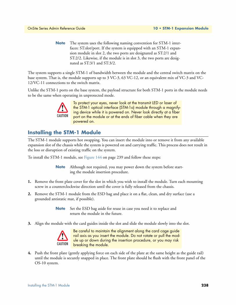
OnSite Series Admin Reference Guide 10 • STM-1 Expansion Module
Note The system uses the following naming convention for STM-1 inter-faces: ST:slot/port. If the system is equipped with an STM-1 expan-sion module in slot 2, the two ports are designated as ST:2/1 and ST:2/2. Likewise, if the module is in slot 3, the two ports are desig-nated as ST:3/1 and ST:3/2.
The system supports a single STM-1 of bandwidth between the module and the central switch matrix on the base system. That is, the module supports up to 3 VC-3, 63 VC-12, or an equivalent mix of VC-3 and VC-12/VC-11 connections to the switch matrix.
Unlike the STM-1 ports on the base system, the payload structure for both STM-1 ports in the module needs to be the same when operating in unprotected mode.
Installing the STM-1 ModuleThe STM-1 module supports hot swapping. You can insert the module into or remove it from any available expansion slot of the chassis while the system is powered on and carrying traffic. This process does not result in the loss or disruption of existing traffic on the system.
To install the STM-1 module, see Figure 144 on page 239 and follow these steps:
Note Although not required, you may power down the system before start-ing the module insertion procedure.
1. Remove the front plate cover for the slot in which you wish to install the module. Turn each mounting screw in a counterclockwise direction until the cover is fully released from the chassis.
2. Remove the STM-1 module from the ESD bag and place it on a flat, clean, and dry surface (use a grounded antistatic mat, if possible).
Note Set the ESD bag aside for reuse in case you need it to replace and return the module in the future.
3. Align the module with the card guides inside the slot and slide the module slowly into the slot.
4. Push the front plate (gently applying force on each side of the plate at the same height as the guide rail) until the module is securely snapped in place. The front plate should be flush with the front panel of the OS-10 system.
To protect your eyes, never look at the transmit LED or laser of the STM-1 optical interface (STM-1o) module through a magnify-ing device while it is powered on. Never look directly at a fiber port on the module or at the ends of fiber cable when they are powered on.
Be careful to maintain the alignment along the card cage guide rail axis as you insert the module. Do not rotate or pull the mod-ule up or down during the insertion procedure, or you may risk breaking the module.
CAUTION
CAUTION
Installing the STM-1 Module 238

OnSite Series Admin Reference Guide 10 • STM-1 Expansion Module
5. Secure the module to the chassis by turning the two mounting screws on the front panel of the module in a clockwise direction.
The STAT LED of the STM-1 module becomes a solid amber light for about 10 seconds after the system detects the module. At this point, use the OnSight Device Manager to set the Administrative Type for the slot in which the module resides to 2-port STM-1o expansion module (or 2-port STM-1 e expansion module). The STAT LED of the module becomes a solid green light when the Administrative Status of the module is enabled and the Operational Status is in service (IS).
Figure 144. Installing the STM-1 Optical Interface Module
Provisioning the STM-1 ModuleTo provision the STM-1 optical interface (STM-1o) module, see Figure 152 and follow these steps:
1. Select the CHASSIS folder from the navigation menu.
2. From the expanded CHASSIS folder, select Slots.
3. On the Slots page, check that the Status for the slot in which the module resides is Full.
Note On the Slots page, the Status indicates the presence of a module in the expansion slots. When a module is physically present and prop-erly inserted in slot 2 or 3, the table entry shows Full for that slot. Otherwise, the table entry shows Empty.
4. Check that the Operational Type for the slot shows: 2-port STM-1o expansion module for the STM-1 optical module.
Note The Operational Type indicates the type of module in the slot. The table entry shows 2-port STM-1o expansion module when the sys-tem has software access and control for the STM-1 module. Other-wise, the entry shows Unknown even when the module is physically present in the slot.
Provisioning the STM-1 Module 239

OnSite Series Admin Reference Guide 10 • STM-1 Expansion Module
Note When the Operational Type is Unknown and the module is securely installed in the chassis, the module may need replacement. Consult your nearest support center or systems engineer servicing the system for technical support.
5. Select the Slot ID for the slot in which the module resides, and click on Properties.
6. In the Slot Properties window, set the Administrative Type to 2-port STM-1o expansion module using the scroll-down button.
7. Set the Administrative Status to Enabled.
8. Click on Apply for the settings to take effect.
Note You can also use the Slot Properties window to check the inventory for the module, including the hardware description, manufacturing part number (MFG P/N), and revision. You can also use the Slot Properties window to verify that the module completed the POST.
Note Click on Close to close the window and finish this task.
At this point, the module is now ready for the provisioning of services using the OnSight Device Manager or NMS.
To provision the STM-1 electrical interface (STM-1e) module, follow the preceeding steps but use 2-port STM-1e expansion module in Step 4 and Step 6.
Figure 145. Provisioning the STM-1 Optical Interface Module
The system displays all STM-1 ports in slot 2 and slot 3 when the Administrative Type for those slots is set to Enabled. The module need not be physically present in the slot for the system to display the ports on the Ports page.
Provisioning the STM-1 Module 240

OnSite Series Admin Reference Guide 10 • STM-1 Expansion Module
You can preconfigure connections to the STM-1 ports before the module is physically present in the slot.
The system maintains all existing connections to the STM-1 expansion ports in the Client Port Mappings and Cross-Connections tables even after physical removal of the module from the slot.
Module AlarmsThe STM-1 module supports the same alarms as the HD-E1 module. Table 80 on page 221 provides a list of the alarms that the system monitors for the STM-1 module.
The ALM (alarm status) LED for each STM-1 port indicates the presence of an active alarm condition of any severity level. The LED is lit according to the color codes in Table 89.
SynchronizationTo configure the system to use STM-1 ports 1 and 2 from an STM-1 module as the primary and secondary ref-erences for synchronization using line timing, follow these steps:
1. Select the SYSTEM folder from the navigation menu.
2. From the expanded SYSTEM folder, select Timing & Sync.
3. On the Timing & Synchronization page, select Auto: STM-1 Expansion port 2/1, port 2/2 using the Timing Mode – Primary/Secondary Source scroll-down button.
4. Click on Apply for the changes to take effect.
Note The system does not allow the change of the timing mode directly from one primary-and secondary-timing-source pair to another. You must first change the timing mode to Internal and then to Auto: STM-1 Expansion port 2/1, port 2/2. The scroll-down list includes Auto: STM-1 Expansion port 3/1, port 3/2, if the system is equipped with an STM-1 module in slot 3.
Downloading Expansion Module FirmwareThe system supports the downloading and installation of new firmware in the STM-1 module. The procedure is the same as that for the HD-E1 module (see “Downloading Expansion Module Firmware” on page 223).
Save the system configuration to prevent the loss of the module settings if a system reboot occurs.
Table 89. ALM (Alarm Status) LED for STM-1 Ports
LED Color Description
Green No alarm is present on the port.Amber An alarm is present on the port.
Off The STM-1 port is disabled.
CAUTION
Module Alarms 241

Chapter 11 Contacting Patton for assistance
Chapter contentsIntroduction ..........................................................................................................................................................54Contact information..............................................................................................................................................54Warranty Service and Returned Merchandise Authorizations (RMAs)...................................................................54
Warranty coverage ..........................................................................................................................................54Out-of-warranty service .............................................................................................................................54Returns for credit ......................................................................................................................................54Return for credit policy .............................................................................................................................55
RMA numbers ................................................................................................................................................55Shipping instructions ................................................................................................................................55
242
OnSite Series Admin Reference Guide 11 • Contacting Patton for assistance
IntroductionThis chapter contains the following information:
• “Contact information”—describes how to contact Patton technical support for assistance.
• “Warranty Service and Returned Merchandise Authorizations (RMAs)”—contains information about the RAS warranty and obtaining a return merchandise authorization (RMA).
Contact informationPatton Electronics offers a wide array of free technical services. If you have questions about any of our other products we recommend you begin your search for answers by using our technical knowledge base. Here, we have gathered together many of the more commonly asked questions and compiled them into a searchable database to help you quickly solve your problems.
• Online support—available at www.patton.com.
• E-mail support—e-mail sent to [email protected] will be answered within 1 business day
• Telephone support—standard telephone support is available Monday through Friday, from 8:00 A.M. to 5:00 P.M. EST (8:00 to 17:00 UTC-5), Monday through Friday by calling +1 (301) 975-1007
Warranty Service and Returned Merchandise Authorizations (RMAs)Patton Electronics is an ISO-9001 certified manufacturer and our products are carefully tested before ship-ment. All of our products are backed by a comprehensive warranty program.
Note If you purchased your equipment from a Patton Electronics reseller, ask your reseller how you should proceed with warranty service. It is often more convenient for you to work with your local reseller to obtain a replacement. Patton services our products no matter how you acquired them.
Warranty coverageOur products are under warranty to be free from defects, and we will, at our option, repair or replace the prod-uct should it fail within one year from the first date of shipment. Our warranty is limited to defects in work-manship or materials, and does not cover customer damage, lightning or power surge damage, abuse, or unauthorized modification.
Out-of-warranty servicePatton services what we sell, no matter how you acquired it, including malfunctioning products that are no longer under warranty. Our products have a flat fee for repairs. Units damaged by lightning or elephants may require replacement.
Returns for creditCustomer satisfaction is important to us, therefore any product may be returned with authorization within 30 days from the shipment date for a full credit of the purchase price. If you have ordered the wrong equipment or you are dissatisfied in any way, please contact us to request an RMA number to accept your return. Patton is not responsible for equipment returned without a Return Authorization.
Introduction 243

OnSite Series Admin Reference Guide 11 • Contacting Patton for assistance
Return for credit policy • Less than 30 days: No Charge. Your credit will be issued upon receipt and inspection of the equipment.
• 30 to 120 days: We will add a 20% restocking charge (crediting your account with 80% of the purchase price).
• Over 120 days: Products will be accepted for repairs only.
RMA numbersRMA numbers are required for all product returns. You can obtain an RMA by doing one of the following:
• Completing a request on the RMA Request page in the Support section at www.patton.com
• By calling +1 (301) 975-1000 and speaking to a Technical Support Engineer
• By sending an e-mail to [email protected]
All returned units must have the RMA number clearly visible on the outside of the shipping container. Please use the original packing material that the device came in or pack the unit securely to avoid damage during shipping.
Shipping instructionsThe RMA number should be clearly visible on the address label. Our shipping address is as follows:
Patton Electronics CompanyRMA#: xxxx7622 Rickenbacker Dr.Gaithersburg, MD 20879-4773 USA
Patton will ship the equipment back to you in the same manner you ship it to us. Patton will pay the return shipping costs.
Warranty Service and Returned Merchandise Authorizations (RMAs) 244

Appendix A Terms and Acronyms
Chapter contentsAbbreviations.......................................................................................................................................................246
245

OnSite Series Admin Reference Guide A • Terms and Acronyms
Abbreviations
Abbreviation Meaning
AAIS Alarm Indication Signal AMI Alternate Mark InversionAU Administrative UnitAUX Auxiliary (port)BBIP Bit Interleaved ParityBBE Background Block ErrorBER Bit Error RateBPV Bipolar ViolationB3ZS Bipolar with 3-zero SubstitutionB8ZS Bipolar with 8-zero SubstitutionCcHEC core Header Error CheckCLI Command Line InterfaceCSU/DSU Channel Service Unit/Data Service UnitC-Tag Customer-assigned tag (for example, VLAN tag)DDNU Do Not Use (for synchronization)EE1 European digital signal hierarchy level 1EB Errored BlockEDC Error Detection CodeEIA Electronics Industries AllianceEOW Engineering OrderwireES Errored SecondETSI European Telecommunications Standards InstituteEXM Extension Header MismatchEXZ Excessive ZerosGGFP Generic Framing ProcedureHHDB3 High-Density Bipolar with 3-zero SubstitutionHP High-order PathHTTP Hyper Text Transfer ProtocolIIP Internet Protocol
Abbreviations 246
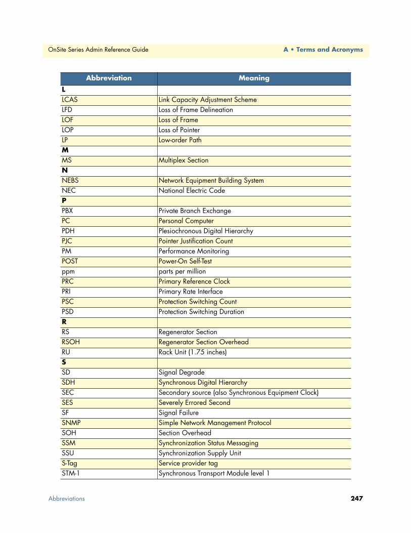
OnSite Series Admin Reference Guide A • Terms and Acronyms
LLCAS Link Capacity Adjustment SchemeLFD Loss of Frame DelineationLOF Loss of FrameLOP Loss of PointerLP Low-order PathMMS Multiplex SectionNNEBS Network Equipment Building SystemNEC National Electric CodePPBX Private Branch ExchangePC Personal ComputerPDH Plesiochronous Digital HierarchyPJC Pointer Justification CountPM Performance MonitoringPOST Power-On Self-Testppm parts per millionPRC Primary Reference ClockPRI Primary Rate InterfacePSC Protection Switching CountPSD Protection Switching DurationRRS Regenerator SectionRSOH Regenerator Section OverheadRU Rack Unit (1.75 inches)SSD Signal DegradeSDH Synchronous Digital HierarchySEC Secondary source (also Synchronous Equipment Clock)SES Severely Errored SecondSF Signal FailureSNMP Simple Network Management ProtocolSOH Section OverheadSSM Synchronization Status MessagingSSU Synchronization Supply UnitS-Tag Service provider tagSTM-1 Synchronous Transport Module level 1
Abbreviation Meaning
Abbreviations 247
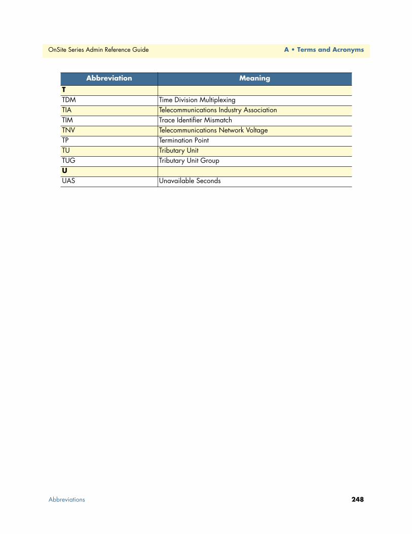
OnSite Series Admin Reference Guide A • Terms and Acronyms
TTDM Time Division MultiplexingTIA Telecommunications Industry AssociationTIM Trace Identifier MismatchTNV Telecommunications Network VoltageTP Termination PointTU Tributary UnitTUG Tributary Unit GroupUUAS Unavailable Seconds
Abbreviation Meaning
Abbreviations 248